EP3525274A1 - Electrode structure and redox flow battery comprising same - Google Patents
Electrode structure and redox flow battery comprising same Download PDFInfo
- Publication number
- EP3525274A1 EP3525274A1 EP18761044.9A EP18761044A EP3525274A1 EP 3525274 A1 EP3525274 A1 EP 3525274A1 EP 18761044 A EP18761044 A EP 18761044A EP 3525274 A1 EP3525274 A1 EP 3525274A1
- Authority
- EP
- European Patent Office
- Prior art keywords
- carbon block
- carbon
- electrode structure
- plate
- monopolar
- Prior art date
- Legal status (The legal status is an assumption and is not a legal conclusion. Google has not performed a legal analysis and makes no representation as to the accuracy of the status listed.)
- Granted
Links
Images


Classifications
-
- H—ELECTRICITY
- H01—ELECTRIC ELEMENTS
- H01M—PROCESSES OR MEANS, e.g. BATTERIES, FOR THE DIRECT CONVERSION OF CHEMICAL ENERGY INTO ELECTRICAL ENERGY
- H01M8/00—Fuel cells; Manufacture thereof
- H01M8/18—Regenerative fuel cells, e.g. redox flow batteries or secondary fuel cells
-
- H—ELECTRICITY
- H01—ELECTRIC ELEMENTS
- H01M—PROCESSES OR MEANS, e.g. BATTERIES, FOR THE DIRECT CONVERSION OF CHEMICAL ENERGY INTO ELECTRICAL ENERGY
- H01M4/00—Electrodes
- H01M4/86—Inert electrodes with catalytic activity, e.g. for fuel cells
-
- H—ELECTRICITY
- H01—ELECTRIC ELEMENTS
- H01M—PROCESSES OR MEANS, e.g. BATTERIES, FOR THE DIRECT CONVERSION OF CHEMICAL ENERGY INTO ELECTRICAL ENERGY
- H01M4/00—Electrodes
- H01M4/86—Inert electrodes with catalytic activity, e.g. for fuel cells
- H01M4/8605—Porous electrodes
-
- H—ELECTRICITY
- H01—ELECTRIC ELEMENTS
- H01M—PROCESSES OR MEANS, e.g. BATTERIES, FOR THE DIRECT CONVERSION OF CHEMICAL ENERGY INTO ELECTRICAL ENERGY
- H01M4/00—Electrodes
- H01M4/86—Inert electrodes with catalytic activity, e.g. for fuel cells
- H01M4/8605—Porous electrodes
- H01M4/8626—Porous electrodes characterised by the form
- H01M4/8631—Bipolar electrodes
-
- H—ELECTRICITY
- H01—ELECTRIC ELEMENTS
- H01M—PROCESSES OR MEANS, e.g. BATTERIES, FOR THE DIRECT CONVERSION OF CHEMICAL ENERGY INTO ELECTRICAL ENERGY
- H01M8/00—Fuel cells; Manufacture thereof
- H01M8/02—Details
- H01M8/0202—Collectors; Separators, e.g. bipolar separators; Interconnectors
- H01M8/023—Porous and characterised by the material
- H01M8/0234—Carbonaceous material
-
- H—ELECTRICITY
- H01—ELECTRIC ELEMENTS
- H01M—PROCESSES OR MEANS, e.g. BATTERIES, FOR THE DIRECT CONVERSION OF CHEMICAL ENERGY INTO ELECTRICAL ENERGY
- H01M8/00—Fuel cells; Manufacture thereof
- H01M8/02—Details
- H01M8/0202—Collectors; Separators, e.g. bipolar separators; Interconnectors
- H01M8/023—Porous and characterised by the material
- H01M8/0241—Composites
- H01M8/0245—Composites in the form of layered or coated products
-
- H—ELECTRICITY
- H01—ELECTRIC ELEMENTS
- H01M—PROCESSES OR MEANS, e.g. BATTERIES, FOR THE DIRECT CONVERSION OF CHEMICAL ENERGY INTO ELECTRICAL ENERGY
- H01M8/00—Fuel cells; Manufacture thereof
- H01M8/02—Details
- H01M8/0202—Collectors; Separators, e.g. bipolar separators; Interconnectors
- H01M8/0247—Collectors; Separators, e.g. bipolar separators; Interconnectors characterised by the form
-
- H—ELECTRICITY
- H01—ELECTRIC ELEMENTS
- H01M—PROCESSES OR MEANS, e.g. BATTERIES, FOR THE DIRECT CONVERSION OF CHEMICAL ENERGY INTO ELECTRICAL ENERGY
- H01M8/00—Fuel cells; Manufacture thereof
- H01M8/02—Details
- H01M8/0271—Sealing or supporting means around electrodes, matrices or membranes
-
- H—ELECTRICITY
- H01—ELECTRIC ELEMENTS
- H01M—PROCESSES OR MEANS, e.g. BATTERIES, FOR THE DIRECT CONVERSION OF CHEMICAL ENERGY INTO ELECTRICAL ENERGY
- H01M8/00—Fuel cells; Manufacture thereof
- H01M8/18—Regenerative fuel cells, e.g. redox flow batteries or secondary fuel cells
- H01M8/184—Regeneration by electrochemical means
- H01M8/188—Regeneration by electrochemical means by recharging of redox couples containing fluids; Redox flow type batteries
-
- H—ELECTRICITY
- H01—ELECTRIC ELEMENTS
- H01M—PROCESSES OR MEANS, e.g. BATTERIES, FOR THE DIRECT CONVERSION OF CHEMICAL ENERGY INTO ELECTRICAL ENERGY
- H01M8/00—Fuel cells; Manufacture thereof
- H01M8/20—Indirect fuel cells, e.g. fuel cells with redox couple being irreversible
-
- Y—GENERAL TAGGING OF NEW TECHNOLOGICAL DEVELOPMENTS; GENERAL TAGGING OF CROSS-SECTIONAL TECHNOLOGIES SPANNING OVER SEVERAL SECTIONS OF THE IPC; TECHNICAL SUBJECTS COVERED BY FORMER USPC CROSS-REFERENCE ART COLLECTIONS [XRACs] AND DIGESTS
- Y02—TECHNOLOGIES OR APPLICATIONS FOR MITIGATION OR ADAPTATION AGAINST CLIMATE CHANGE
- Y02E—REDUCTION OF GREENHOUSE GAS [GHG] EMISSIONS, RELATED TO ENERGY GENERATION, TRANSMISSION OR DISTRIBUTION
- Y02E60/00—Enabling technologies; Technologies with a potential or indirect contribution to GHG emissions mitigation
- Y02E60/30—Hydrogen technology
- Y02E60/50—Fuel cells
Definitions
- the present specification relates to an electrode structure, and a redox flow battery comprising the same.
- Power storage technology is an important technology for efficient use across the whole energy such as efficiency of power usage, enhancing capability or reliability of a power supply system, expansion of introduction of new and renewable energy with large variation over time, or energy recovery of a moving body, and its development potential and demands for social contribution have been increasing.
- a flow battery is formed so that cathode and anode electrodes are located on both sides with a separator as a center.
- plates for battery fastening and electric conduction are each provided, and the constitution comprises a cathode tank and an anode tank containing an electrolyte, and an inlet through which the electrolyte enters and an outlet through which the electrolyte comes out again.
- the present specification is directed to providing an electrode structure, and a redox flow battery comprising the same.
- One embodiment of the present specification provides an electrode structure comprising a carbon block having pores; and a flow frame having the carbon block accommodated on one surface or both surfaces, wherein the carbon block has porosity of greater than or equal to 5% and less than or equal to 70%, and the carbon block has compressive strength of 20 MPa or greater.
- a redox flow battery comprising a first end plate; a first monopolar plate; a separator; a second monopolar plate; and a second end plate, wherein the first end plate, the first monopolar plate, the separator, the second monopolar plate, and the second end plate are provided in consecutive order, wherein at least one of the first and the second monopolar plates is the electrode structure described above.
- An electrode of an electrode structure according to the present specification has advantages of being hardly compressed by a fastening pressure of a battery cell, and maintaining porosity when manufactured.
- a redox flow battery according to the present specification has an advantage of supplying an electrolyte liquid to an electrode in a high flow rate.
- An electrode structure of the present specification comprises a carbon block having pores; and a flow frame having the carbon block accommodated on one surface or both surfaces.
- the electrode structure comprises a carbon block; and a flow frame having the carbon block accommodated on one surface
- the electrode structure is a monopolar plate.
- the monopolar plate means a plate in which only one surface provided with the carbon block performs a role of an electrode.
- the electrode structure When the electrode structure comprises a carbon block; and a flow frame having the carbon block accommodated on both surfaces, the electrode structure is a bipolar plate.
- the bipolar plate means a plate in which both surfaces provided with the carbon block all perform a role of an electrode. Electrodes on the both surfaces of the bipolar plate are either electrodes opposite to each other or the same electrodes, and specifically, when the electrode on one surface is an anode, the electrode on the other surface may perform a role of a cathode.
- the carbon block may have porosity of greater than or equal to 5% and less than or equal to 70%, specifically greater than or equal to 20% and less than or equal to 50%, and more specifically greater than or equal to 30% and less than or equal to 40%.
- changes in the carbon block may be 10% or less, specifically 2% or less, and more specifically, the carbon block may hardly change.
- the carbon block hardly shrinks when fastening a flow battery cell using the carbon block, and porosity of the carbon block may be maintained when manufactured even in the fastened battery cell.
- the change in the porosity means a difference between porosity before applying a pressure and porosity after applying a pressure.
- An average thickness of the carbon block may be selected considering a depth of the carbon block accommodating groove and the fastening structure, and specifically, an average thickness of the carbon block may be the same as an average depth of the carbon block accommodating groove, or may be smaller or larger than an average depth of the carbon block accommodating groove.
- an average thickness of the carbon block may be the same as an average depth of the carbon block accommodating groove, or may be smaller or larger than an average depth of the carbon block accommodating groove.
- the carbon block thickness is generally 2 mm, however, depending on the gasket shape and thickness, the carbon block thickness may be larger or smaller than the accommodating groove depth.
- the carbon block may be prepared to be porous by filling a block-type mold with a composition comprising a spherical phenol resin and a binder, compressing and then carbonizing the result.
- the carbon block may be prepared to be porous by preparing a spherical phenol resin, filling a block-type mold with a composition comprising the spherical phenol resin and liquid polyphenol, compressing the result, and then going through drying/degreasing/sintering/high purification processes.
- the spherical phenol resin is a polymer
- the phenol resin means a thermocurable resin comprising resins obtained from phenols (phenol, cresol, xylenol, resorcinol) and aldehydes (formaldehyde, acetaldehyde, furfural), and modified resins thereof.
- the liquid polyphenol is a relatively low molecular material, is a liquid at room temperature, and may perform a role as a binder resin linking the spherical phenol resin.
- particles of the used spherical phenol resin may be spherical polyresin particles having an average diameter of 100 ⁇ m to 800 ⁇ m.
- the carbon block has compressive strength of 20 MPa or greater, and specifically, 25 MPa or greater.
- the carbon block hardly shrinks when fastening a flow battery cell using the carbon block, and porosity of the carbon block may be maintained when manufactured even in the fastened battery cell.
- the higher the compressive strength the better, and therefore, the upper limit is not specified.
- the compressive strength means a value measured using a test analysis method specified in the KS L 1601:2006.
- the carbon block has sintered density of 0.6 g/cm 3 or greater, and specifically 0.7 g/cm 3 or greater.
- the carbon block hardly shrinks when fastening a flow battery cell using the carbon block, and porosity of the carbon block may be maintained when manufactured even in the fastened battery cell.
- the higher the sintered density the better, and therefore, the upper limit is not specified.
- the sintered density means a value measured using a test analysis method specified in the KS L 3409:2010.
- the carbon block may have an average pore size of greater than or equal to 25 ⁇ m and less than or equal to 200 ⁇ m, specifically greater than or equal to 70 ⁇ m and less than or equal to 120 ⁇ m, and more specifically greater than or equal to 90 ⁇ m and less than or equal to 110 ⁇ m.
- the carbon block may additionally go through heat treatment before battery fastening.
- the carbon block may be heat treated for a certain period of time or longer at a high temperature while supplying air.
- the heat treatment temperature may be around 500°C
- the heat treatment time may be longer than or equal to 5 hours and shorter than or equal to 7 hours.
- an interfacial resistance reducing layer comprising any one selected from among carbon paper, carbon cloth and thin carbon felt may be further included and provided.
- the electrode structure may further comprise carbon paper provided on one surface or both surfaces of the carbon block. This may lower interfacial resistance and enhance a reaction rate.
- the interfacial resistance reducing layer may have a thickness of greater than or equal to 0.01 mm and less than or equal to 1 mm, and greater than or equal to 0.1 mm and less than or equal to 0.7 mm. This may lower interfacial resistance and enhance a reaction rate.
- an average thickness of the carbon block may be selected considering the thickness of the interfacial resistance reducing layer.
- the carbon block provided with the interfacial resistance reducing layer on at least one surface may have an average thickness sum of the carbon block and interfacial resistance reducing layer being the same as an average depth of the carbon block accommodating groove, or smaller or larger than an average depth of the carbon block accommodating groove.
- the carbon block accommodating groove has an average depth of 2 mm
- the carbon block may have an average thickness of 2 mm
- the interfacial resistance reducing layer may have a thickness of 0.5 mm.
- Carbon paper means a material such as a thin paper prepared by coating a carbon material such as carbon black, carbon fiber or carbon nanotubes with a binder resin, and then heating the result.
- Carbon fiber is a fibrous carbon material having a carbon content of 90% or greater in a weight ratio.
- the strength is approximately 10 times that of steel, and is a light weight material with the weight being just 25%.
- the carbon fiber has high thermal conductivity and low coefficient of thermal expansion, excellent electrical conductivity and chemical resistance in addition to excellent mechanical properties.
- the carbon cloth is woven with carbon fiber (woven fabric), and the carbon felt is made by, like a non-woven fabric, adhering carbon fiber by thermal adhering or using chemical agents, or tangling with a needle and the like, that is, is a felt type prepared without weaving carbon fiber (non-woven fabric).
- the carbon felt when carbon felt having a thickness of 5 mm is inserted to a felt accommodating groove of a flow frame and the accommodating groove has a depth of 3 mm, the carbon felt may be considered to have compressibility of 40%.
- the electrode structure of the present specification being provided with a carbon block, changes in the thickness are small by the pressure during battery fastening, and accordingly, an advantage of favorable electrolyte liquid flowability is obtained by almost maintaining porosity and pore sizes of the carbon block while having low interfacial resistance.
- T2 of the carbon block after the fastening is almost the same as T1, a thickness of the carbon block before fastening.
- the flow frame has a structure capable of accommodating a carbon block on one surface or both surfaces, a flow path capable of supplying and discharging an electrolyte liquid to the carbon block, a member sealing so as to prevent leakage of the electrolyte liquid, and a current collecting structure formed therein.
- the flow frame may be provided with a carbon block accommodating groove on one surface or both surfaces.
- a carbon block may be inserted, or a carbon block provided with carbon paper on at least one surface may be inserted.
- a graphite plate capable of being in contact with the accommodated carbon block, and collecting a current by a surface opposite to the surface in contact with the carbon block adjoining a current collector may be provided so as to prevent electrolyte liquid leakage.
- the flow frame may be provided with a carbon block accommodating hole perforated in a thickness direction.
- the electrode structure When the flow frame is provided with a carbon block accommodating hole, the electrode structure further comprises a graphite plate provided on one surface of the carbon block, and the carbon block provided with the graphite plate on the one surface may be inserted to the carbon block accommodating hole of the flow frame.
- sealing may be carried out so as to prevent electrolyte liquid leakage between the carbon block accommodating hole of the flow frame and the graphite plate.
- a redox flow battery of the present specification comprises a first end plate; a first monopolar plate; a separator; a second monopolar plate; and a second end plate in consecutive order.
- At least one of the first and the second monopolar plates may be the electrode structure described above. Specifically, any one of the first and the second monopolar plates may be the electrode structure described above, or the first and the second monopolar plates may each be the electrode structure described above.
- the monopolar plate means a plate in which only one surface provided with the carbon block performs a role of an electrode, and therefore, at least one of the first and the second monopolar plates may be an electrode structure comprising a flow frame accommodating a carbon block on one surface.
- the sum of average thicknesses of the carbon blocks each accommodated in the first and the second monopolar plates may be the same as or smaller than the sum of an average depth of the carbon block accommodating groove of each of the first and the second monopolar plates and a pressurized thickness of a sealing member when fastening the redox flow battery.
- the redox flow battery may further comprise one or more bipolar plates between the first and the second monopolar plates. At least one of the one or more bipolar plates may be the electrode structure described above.
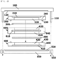
- one bipolar plate (600) may be further included between the first and the second monopolar plates (200, 400).
- the bipolar plate means a plate in which both surfaces provided with the carbon block all perform a role of an electrode, and therefore, the bipolar plate comprising the above-described electrode structure may be an electrode structure comprising a carbon block; and a flow frame accommodating the carbon block on both surfaces.
- the redox flow battery may further comprise a separator between the first monopolar plate and the bipolar plate and between the second monopolar plate and the bipolar plate. Specifically, as illustrated in FIG. 6 , a separator (300) provided between the first monopolar plate (200) and the bipolar plate (600) and between the second monopolar plate (400) and the bipolar plate (600) may be further included.
- a separator provided between the two or more bipolar plates may be further included.
- the separator is not particularly limited and may employ materials generally used in the art, and for example, may be Nafion.
- the redox flow battery may further comprise a sealing member provided between the first and the second monopolar plates.
- the sealing member is not particularly limited as long as it is a structure and a material capable of sealing the first and the second monopolar plates, and for example, may be a gasket line inserted to a groove formed around the carbon block accommodated in the first and the second monopolar plates, or a sealing sheet having a through hole so as not to cover the carbon block accommodated in the first and the second monopolar plates.
- changes in the porosity of the carbon block may be 10% or less, and specifically 2% or less. This has an advantage in that target porosity is almost maintained even after fastening a battery, and a favorable electrolyte liquid flow is obtained.
- torque generally applied to the battery cell may be greater than or equal to 50 kgf•cm and less than or equal to 300 kgf•cm, and specifically, greater than or equal to 100 kgf•cm and less than or equal to 250 kgf•cm.
- a fuel cell comprising the electrode structure of the present specification is provided.
- the electrode structure of the present specification may be each monopolar plate or bipolar plate provided on one surface or both surfaces of a membrane electrode assembly (MEA) in the fuel cell.
- MEA membrane electrode assembly
- the electrode structure of the present specification may replace a plate provided with a gas diffusion layer and a flow path of the membrane electrode assembly.
- the electrode structure of the present disclosure may replace a plate provided with a gas diffusion layer and a flow path of the membrane electrode assembly even when a separate flow path is not formed in the carbon block.
- GF040H carbon paper manufactured by JNTG having a thickness of 0.4 mm was laminated on each of both surfaces of a PC009 porous carbon block manufactured by COMEX CARBON (porosity: 35.64%, thickness: 2.3 mm, pressure: 30 kgf/cm 2 , compressive strength: 29 ⁇ 2 MPa, sintering density: 0.76 g/cm 3 when preparing carbon block).
- the carbon block having the carbon paper laminated on both surfaces was inserted to a flow frame having an accommodating groove with a size of 325 cm 2 and a depth of 2.5 mm provided on one surface.
- Nafion212 was provided as a separator, and the result was pressurized with torque of 250 kgf•cm to fasten an end cell.
- GF040H carbon paper manufactured by JNTG having a thickness of 0.4 mm was laminated on each of both surfaces of a PC005 porous carbon block manufactured by COMEX CARBON (porosity: 35.62%, thickness: 2.3 mm, pressure: 50 kgf/cm 2 , compressive strength: 29 ⁇ 3 MPa, sintering density: 0.75 g/cm 3 when preparing carbon block).
- the carbon block having the carbon paper laminated on both surfaces was inserted to a flow frame having an accommodating groove with a size of 5 cm ⁇ 5 cm and a depth of 2.5 mm provided on one surface.
- Nafion212 was provided as a separator, and the result was pressurized with torque of 250 kgf•cm to fasten an end cell.
- Example 2 An end cell was fastened in the same manner as in Example 2 except that, before fastening the end cell, the carbon block of Example 2 was heat treated for 6 hours at a high temperature (500°C) while supplying air.
- a high temperature 500°C
- An end cell was fastened in the same manner as in Example 1 except that carbon felt having a thickness of 4 mm and porosity of 90% (XF30A manufactured by TOYOBO CO., LTD.) was used instead of the carbon block having carbon paper laminated on both surfaces.
- the accommodating groove has a depth of 2.5 mm, and therefore, compressibility of the end cell-fastened carbon felt was approximately 38%.
- Example 1 L of a commercial electrolyte liquid manufactured by OXKEM Limited was supplied to each electrode by circulation, and charge and discharge was performed under a constant current (CC) mode in a 0.8 V to 1.6 V range.
- CC constant current
- the charge and discharge rates were increased by 50 mA/cm 2 from 50 mA/cm 2 to 250 mA/cm 2 , charge and discharge was carried out 3 times for each step, and performance of the third charge and discharge cycle is shown in the following Table 1.
- Table 1 Example 1 Comparative Example mA/cm 2 Dch. mAh CE% VE% EE% Dch.
- Dch. discharge capacity
- CE current efficiency
- VE voltage efficiency
- EE energy efficiency
- mA/cm 2 current per electrode active area
- Example 1 had somewhat low voltage efficiency due to an increase in the resistance caused by an increase in the number of interfaces, however, under a high current (high output) evaluation condition of 250 mA/cm 2 , energy efficiency was reversed compared to Comparative Example. This means that an electrolyte liquid needs to be used in a high flow rate when current density increases.
- the cell differential pressure was 0.65 bar.
- the flow rate of the electrolyte liquid of Example 1 using the porous carbon block increased by 57% compared to Comparative Example.
- Example 2 Example 3 Dch. mAh CE% VE% EE% Dch. mAh CE% VE% EE% 10 Times 632 95.9% 59.0% 56.6% 1062 96.3% 65.6% 63.2%
- Example 3 using the heat treated carbon block was identified to have significantly enhanced performance compared to Example 2.
- the performance enhancement was identified to be from, through the high temperature heat treatment, providing hydrophilicity to the material and forming oxygen functional groups.
- the carbon blocks of Examples 1 to 3 each had compressive strength of 29 ⁇ 2 MPa and 29 ⁇ 2 MPa, and it was identified that, even when applying more pressure, the shape was maintained, and when applying a pressure of certain level or higher, the carbon block was broken rather than compressed while the thickness changed.
Landscapes
- Chemical & Material Sciences (AREA)
- Chemical Kinetics & Catalysis (AREA)
- Electrochemistry (AREA)
- General Chemical & Material Sciences (AREA)
- Life Sciences & Earth Sciences (AREA)
- Engineering & Computer Science (AREA)
- Manufacturing & Machinery (AREA)
- Sustainable Development (AREA)
- Sustainable Energy (AREA)
- Composite Materials (AREA)
- Fuel Cell (AREA)
- Inert Electrodes (AREA)
Abstract
Description
- The present specification claims priority to and the benefits of Korean Patent Application No.
10-2017-0026394 - The present specification relates to an electrode structure, and a redox flow battery comprising the same.
- Power storage technology is an important technology for efficient use across the whole energy such as efficiency of power usage, enhancing capability or reliability of a power supply system, expansion of introduction of new and renewable energy with large variation over time, or energy recovery of a moving body, and its development potential and demands for social contribution have been increasing.
- Studies on secondary batteries have been actively progressed in order to adjust a supply-demand balance of semi-autonomous regional power supply systems such as microgrids and properly distribute an uneven output of new and renewable energy generation such as wind or sunlight generation, and to control effects of voltages and frequency fluctuations occurring from differences with existing power systems, and expectations for secondary battery utilization in such fields are increasing.
- When examining properties required for secondary batteries to be used for large capacity power storage, energy storage density needs to be high, and as a high capacity and high efficiency secondary battery most suited for such properties, a flow battery has received most attention.
- A flow battery is formed so that cathode and anode electrodes are located on both sides with a separator as a center.
- Outside the electrodes, plates for battery fastening and electric conduction are each provided, and the constitution comprises a cathode tank and an anode tank containing an electrolyte, and an inlet through which the electrolyte enters and an outlet through which the electrolyte comes out again.
- The present specification is directed to providing an electrode structure, and a redox flow battery comprising the same.
- One embodiment of the present specification provides an electrode structure comprising a carbon block having pores; and a flow frame having the carbon block accommodated on one surface or both surfaces, wherein the carbon block has porosity of greater than or equal to 5% and less than or equal to 70%, and the carbon block has compressive strength of 20 MPa or greater.
- Another embodiment of the present specification provides a redox flow battery comprising a first end plate; a first monopolar plate; a separator; a second monopolar plate; and a second end plate, wherein the first end plate, the first monopolar plate, the separator, the second monopolar plate, and the second end plate are provided in consecutive order, wherein at least one of the first and the second monopolar plates is the electrode structure described above.
- An electrode of an electrode structure according to the present specification has advantages of being hardly compressed by a fastening pressure of a battery cell, and maintaining porosity when manufactured.
- A redox flow battery according to the present specification has an advantage of supplying an electrolyte liquid to an electrode in a high flow rate.
-
-
FIG. 1 is an exploded sectional view of fastening a battery using an electrode structure according to an existing technology. -
FIG. 2 is a sectional view of a battery fastened using an electrode structure according to an existing technology. -
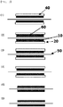
FIG. 3 is a sectional view of an electrode structure of an embodiment according to the present specification. -
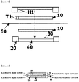
FIG. 4 is an exploded sectional view of fastening a battery using an electrode structure of one embodiment according to the present specification. -
FIG. 5 is a sectional view of a battery fastened using an electrode structure of one embodiment according to the present specification. -
FIG. 6 is an exploded sectional view of a redox flow battery using an electrode structure of another embodiment according to the present specification. -
FIG. 7 is an image observing a carbon block according to the present specification at a magnification of 150 using a scanning electron microscope. - Hereinafter, the present specification will be described in detail.
- An electrode structure of the present specification comprises a carbon block having pores; and a flow frame having the carbon block accommodated on one surface or both surfaces.
- When the electrode structure comprises a carbon block; and a flow frame having the carbon block accommodated on one surface, the electrode structure is a monopolar plate. Herein, the monopolar plate means a plate in which only one surface provided with the carbon block performs a role of an electrode.
- When the electrode structure comprises a carbon block; and a flow frame having the carbon block accommodated on both surfaces, the electrode structure is a bipolar plate. Herein, the bipolar plate means a plate in which both surfaces provided with the carbon block all perform a role of an electrode. Electrodes on the both surfaces of the bipolar plate are either electrodes opposite to each other or the same electrodes, and specifically, when the electrode on one surface is an anode, the electrode on the other surface may perform a role of a cathode.
- The carbon block may have porosity of greater than or equal to 5% and less than or equal to 70%, specifically greater than or equal to 20% and less than or equal to 50%, and more specifically greater than or equal to 30% and less than or equal to 40%.
- When fastening a flow battery, changes in the carbon block may be 10% or less, specifically 2% or less, and more specifically, the carbon block may hardly change. In this case, the carbon block hardly shrinks when fastening a flow battery cell using the carbon block, and porosity of the carbon block may be maintained when manufactured even in the fastened battery cell. Herein, the change in the porosity means a difference between porosity before applying a pressure and porosity after applying a pressure.
- An average thickness of the carbon block may be selected considering a depth of the carbon block accommodating groove and the fastening structure, and specifically, an average thickness of the carbon block may be the same as an average depth of the carbon block accommodating groove, or may be smaller or larger than an average depth of the carbon block accommodating groove. For example, when the accommodating groove has a depth of 2 mm, the carbon block thickness is generally 2 mm, however, depending on the gasket shape and thickness, the carbon block thickness may be larger or smaller than the accommodating groove depth. Specifically, when a gasket sheet is used in the whole non-conducting region of the flow frame, an effect of deepening the carbon block accommodating groove depth as the thickness of the used gasket is obtained, however, as another example, when, instead of the surface gasket type, using an o-ring- or cord o-ring-type gasket by inserting to an engrave patterned groove, an increase in the accommodating groove depth may not be obtained.
- The carbon block may be prepared to be porous by filling a block-type mold with a composition comprising a spherical phenol resin and a binder, compressing and then carbonizing the result.
- The carbon block may be prepared to be porous by preparing a spherical phenol resin, filling a block-type mold with a composition comprising the spherical phenol resin and liquid polyphenol, compressing the result, and then going through drying/degreasing/sintering/high purification processes.
- Herein, the spherical phenol resin is a polymer, and the phenol resin means a thermocurable resin comprising resins obtained from phenols (phenol, cresol, xylenol, resorcinol) and aldehydes (formaldehyde, acetaldehyde, furfural), and modified resins thereof.
- The liquid polyphenol is a relatively low molecular material, is a liquid at room temperature, and may perform a role as a binder resin linking the spherical phenol resin.
- Herein, particles of the used spherical phenol resin may be spherical polyresin particles having an average diameter of 100 µm to 800 µm.
- The carbon block has compressive strength of 20 MPa or greater, and specifically, 25 MPa or greater. In this case, the carbon block hardly shrinks when fastening a flow battery cell using the carbon block, and porosity of the carbon block may be maintained when manufactured even in the fastened battery cell. Herein, the higher the compressive strength, the better, and therefore, the upper limit is not specified. Herein, the compressive strength means a value measured using a test analysis method specified in the KS L 1601:2006.
- The carbon block has sintered density of 0.6 g/cm3 or greater, and specifically 0.7 g/cm3 or greater. In this case, the carbon block hardly shrinks when fastening a flow battery cell using the carbon block, and porosity of the carbon block may be maintained when manufactured even in the fastened battery cell. Herein, the higher the sintered density, the better, and therefore, the upper limit is not specified. Herein, the sintered density means a value measured using a test analysis method specified in the KS L 3409:2010.
- The carbon block may have an average pore size of greater than or equal to 25 µm and less than or equal to 200 µm, specifically greater than or equal to 70 µm and less than or equal to 120 µm, and more specifically greater than or equal to 90 µm and less than or equal to 110 µm.
- The carbon block may additionally go through heat treatment before battery fastening. Specifically, the carbon block may be heat treated for a certain period of time or longer at a high temperature while supplying air. Herein, the heat treatment temperature may be around 500°C, and the heat treatment time may be longer than or equal to 5 hours and shorter than or equal to 7 hours.
- On at least one surface of the carbon block, an interfacial resistance reducing layer comprising any one selected from among carbon paper, carbon cloth and thin carbon felt may be further included and provided. Specifically, the electrode structure may further comprise carbon paper provided on one surface or both surfaces of the carbon block. This may lower interfacial resistance and enhance a reaction rate.
- The interfacial resistance reducing layer may have a thickness of greater than or equal to 0.01 mm and less than or equal to 1 mm, and greater than or equal to 0.1 mm and less than or equal to 0.7 mm. This may lower interfacial resistance and enhance a reaction rate.
- When providing the interfacial resistance reducing layer on at least one surface of the carbon block, an average thickness of the carbon block may be selected considering the thickness of the interfacial resistance reducing layer. Specifically, the carbon block provided with the interfacial resistance reducing layer on at least one surface may have an average thickness sum of the carbon block and interfacial resistance reducing layer being the same as an average depth of the carbon block accommodating groove, or smaller or larger than an average depth of the carbon block accommodating groove. For example, when the carbon block accommodating groove has an average depth of 2 mm, the carbon block may have an average thickness of 2 mm, and the interfacial resistance reducing layer may have a thickness of 0.5 mm.
- Carbon paper means a material such as a thin paper prepared by coating a carbon material such as carbon black, carbon fiber or carbon nanotubes with a binder resin, and then heating the result.
- Herein, the carbon cloth and the carbon felt are prepared with carbon fiber. Carbon fiber is a fibrous carbon material having a carbon content of 90% or greater in a weight ratio. The strength is approximately 10 times that of steel, and is a light weight material with the weight being just 25%. The carbon fiber has high thermal conductivity and low coefficient of thermal expansion, excellent electrical conductivity and chemical resistance in addition to excellent mechanical properties.
- The carbon cloth (carbon sheet) is woven with carbon fiber (woven fabric), and the carbon felt is made by, like a non-woven fabric, adhering carbon fiber by thermal adhering or using chemical agents, or tangling with a needle and the like, that is, is a felt type prepared without weaving carbon fiber (non-woven fabric).
- Based on
FIG. 1 and FIG. 2 , when using carbon felt (1) instead of the carbon block of the present specification, and inserting the carbon felt having a thickness of t1 before unit battery fastening to a carbon felt accommodating groove (4) having a depth of h1 and fastening the unit battery, the thickness of the carbon felt changes to t2. Herein, compressibility of the carbon felt is calculated as {(t1-t2)×100}/t1. As the carbon felt compressibility increases, an effect of reducing interfacial resistance between materials is obtained, however, electrolyte liquid flowability may worsen since porosity of the carbon felt decreases. - For example, when carbon felt having a thickness of 5 mm is inserted to a felt accommodating groove of a flow frame and the accommodating groove has a depth of 3 mm, the carbon felt may be considered to have compressibility of 40%.
- However, by the electrode structure of the present specification being provided with a carbon block, changes in the thickness are small by the pressure during battery fastening, and accordingly, an advantage of favorable electrolyte liquid flowability is obtained by almost maintaining porosity and pore sizes of the carbon block while having low interfacial resistance.
- Based on
FIG. 4 and FIG. 5 , when inserting a carbon block having a thickness of T1 before unit battery fastening to a carbon block accommodating groove (30) having a depth of HI and fastening the unit battery, T2 of the carbon block after the fastening is almost the same as T1, a thickness of the carbon block before fastening. - The flow frame has a structure capable of accommodating a carbon block on one surface or both surfaces, a flow path capable of supplying and discharging an electrolyte liquid to the carbon block, a member sealing so as to prevent leakage of the electrolyte liquid, and a current collecting structure formed therein.
- The flow frame may be provided with a carbon block accommodating groove on one surface or both surfaces. To the carbon block accommodating groove, a carbon block may be inserted, or a carbon block provided with carbon paper on at least one surface may be inserted.
- In the flow frame, a graphite plate capable of being in contact with the accommodated carbon block, and collecting a current by a surface opposite to the surface in contact with the carbon block adjoining a current collector may be provided so as to prevent electrolyte liquid leakage.
- The flow frame may be provided with a carbon block accommodating hole perforated in a thickness direction.
- When the flow frame is provided with a carbon block accommodating hole, the electrode structure further comprises a graphite plate provided on one surface of the carbon block, and the carbon block provided with the graphite plate on the one surface may be inserted to the carbon block accommodating hole of the flow frame. Herein, sealing may be carried out so as to prevent electrolyte liquid leakage between the carbon block accommodating hole of the flow frame and the graphite plate.
- A redox flow battery of the present specification comprises a first end plate; a first monopolar plate; a separator; a second monopolar plate; and a second end plate in consecutive order.
- At least one of the first and the second monopolar plates may be the electrode structure described above. Specifically, any one of the first and the second monopolar plates may be the electrode structure described above, or the first and the second monopolar plates may each be the electrode structure described above.
- Herein, the monopolar plate means a plate in which only one surface provided with the carbon block performs a role of an electrode, and therefore, at least one of the first and the second monopolar plates may be an electrode structure comprising a flow frame accommodating a carbon block on one surface.
- When the first and the second monopolar plates each comprise the electrode structure, the sum of average thicknesses of the carbon blocks each accommodated in the first and the second monopolar plates may be the same as or smaller than the sum of an average depth of the carbon block accommodating groove of each of the first and the second monopolar plates and a pressurized thickness of a sealing member when fastening the redox flow battery.
- The redox flow battery may further comprise one or more bipolar plates between the first and the second monopolar plates. At least one of the one or more bipolar plates may be the electrode structure described above.
- As illustrated in
FIG. 6 , one bipolar plate (600) may be further included between the first and the second monopolar plates (200, 400). - Herein, the bipolar plate means a plate in which both surfaces provided with the carbon block all perform a role of an electrode, and therefore, the bipolar plate comprising the above-described electrode structure may be an electrode structure comprising a carbon block; and a flow frame accommodating the carbon block on both surfaces.
- The redox flow battery may further comprise a separator between the first monopolar plate and the bipolar plate and between the second monopolar plate and the bipolar plate. Specifically, as illustrated in
FIG. 6 , a separator (300) provided between the first monopolar plate (200) and the bipolar plate (600) and between the second monopolar plate (400) and the bipolar plate (600) may be further included. - When the redox flow battery comprises two or more bipolar plates, a separator provided between the two or more bipolar plates may be further included.
- The separator is not particularly limited and may employ materials generally used in the art, and for example, may be Nafion.
- The redox flow battery may further comprise a sealing member provided between the first and the second monopolar plates.
- The sealing member is not particularly limited as long as it is a structure and a material capable of sealing the first and the second monopolar plates, and for example, may be a gasket line inserted to a groove formed around the carbon block accommodated in the first and the second monopolar plates, or a sealing sheet having a through hole so as not to cover the carbon block accommodated in the first and the second monopolar plates.
- When fastening the redox flow battery, changes in the porosity of the carbon block may be 10% or less, and specifically 2% or less. This has an advantage in that target porosity is almost maintained even after fastening a battery, and a favorable electrolyte liquid flow is obtained.
- When fastening the redox flow battery, torque generally applied to the battery cell may be greater than or equal to 50 kgf•cm and less than or equal to 300 kgf•cm, and specifically, greater than or equal to 100 kgf•cm and less than or equal to 250 kgf•cm.
- A fuel cell comprising the electrode structure of the present specification is provided.
- The electrode structure of the present specification may be each monopolar plate or bipolar plate provided on one surface or both surfaces of a membrane electrode assembly (MEA) in the fuel cell. Herein, the electrode structure of the present specification may replace a plate provided with a gas diffusion layer and a flow path of the membrane electrode assembly. Particularly, the electrode structure of the present disclosure may replace a plate provided with a gas diffusion layer and a flow path of the membrane electrode assembly even when a separate flow path is not formed in the carbon block.
- Hereinafter, the present specification will be described in more detail with reference to examples. However, the following examples are for illustrative purposes only, and not to limit the present specification.
- GF040H (carbon paper) manufactured by JNTG having a thickness of 0.4 mm was laminated on each of both surfaces of a PC009 porous carbon block manufactured by COMEX CARBON (porosity: 35.64%, thickness: 2.3 mm, pressure: 30 kgf/cm2, compressive strength: 29±2 MPa, sintering density: 0.76 g/cm3 when preparing carbon block).
- The carbon block having the carbon paper laminated on both surfaces was inserted to a flow frame having an accommodating groove with a size of 325 cm2 and a depth of 2.5 mm provided on one surface.
- Nafion212 was provided as a separator, and the result was pressurized with torque of 250 kgf•cm to fasten an end cell.
- GF040H (carbon paper) manufactured by JNTG having a thickness of 0.4 mm was laminated on each of both surfaces of a PC005 porous carbon block manufactured by COMEX CARBON (porosity: 35.62%, thickness: 2.3 mm, pressure: 50 kgf/cm2, compressive strength: 29±3 MPa, sintering density: 0.75 g/cm3 when preparing carbon block).
- The carbon block having the carbon paper laminated on both surfaces was inserted to a flow frame having an accommodating groove with a size of 5 cm×5 cm and a depth of 2.5 mm provided on one surface.
- Nafion212 was provided as a separator, and the result was pressurized with torque of 250 kgf•cm to fasten an end cell.
- An end cell was fastened in the same manner as in Example 2 except that, before fastening the end cell, the carbon block of Example 2 was heat treated for 6 hours at a high temperature (500°C) while supplying air.
- An end cell was fastened in the same manner as in Example 1 except that carbon felt having a thickness of 4 mm and porosity of 90% (XF30A manufactured by TOYOBO CO., LTD.) was used instead of the carbon block having carbon paper laminated on both surfaces.
- Herein, the accommodating groove has a depth of 2.5 mm, and therefore, compressibility of the end cell-fastened carbon felt was approximately 38%.
- To each of the end cells manufactured in Example 1 and Comparative Example, 1 L of a commercial electrolyte liquid manufactured by OXKEM Limited was supplied to each electrode by circulation, and charge and discharge was performed under a constant current (CC) mode in a 0.8 V to 1.6 V range. Herein, the charge and discharge rates were increased by 50 mA/cm2 from 50 mA/cm2 to 250 mA/cm2, charge and discharge was carried out 3 times for each step, and performance of the third charge and discharge cycle is shown in the following Table 1.
[Table 1] Example 1 Comparative Example mA/cm2 Dch. mAh CE% VE% EE% Dch. mAh CE% VE % EE% 50 34468 90.4 91.9 83.1 33413 90.8 92.5 84.0 100 29954 94.6 84.8 80.2 28978 94.2 85.8 80.8 150 24583 95.9 78.3 75.1 23599 95.2 79.4 75.6 200 18465 97.2 72.0 70.0 17138 96.5 72.9 70.3 250 10953 98.3 65.1 64.0 9400 97.0 65.4 63.4 - Dch. (discharge capacity), CE (current efficiency), VE (voltage efficiency), EE (energy efficiency), mA/cm2 (current per electrode active area)
- It was identified that Example 1 had somewhat low voltage efficiency due to an increase in the resistance caused by an increase in the number of interfaces, however, under a high current (high output) evaluation condition of 250 mA/cm2, energy efficiency was reversed compared to Comparative Example. This means that an electrolyte liquid needs to be used in a high flow rate when current density increases.
- Two monopolar plates and two bipolar plates using the same battery (the carbon block having carbon paper laminated on both surfaces) on both surfaces of Example 1 were stacked in 3 cells, and an increase in the flow rate was checked.
- Meanwhile, two monopolar plates and two bipolar plates using the same battery (carbon felt) of on both surfaces Comparative Example were stacked in 3 cells, and an increase in the flow rate was checked.
- Herein, the cell differential pressure was 0.65 bar.
- Since an electrolyte liquid rate is somewhat different depending on the state of charge (SOC), the experimental values of the following Table 2 were measured while the (+) electrode electrolyte liquid was in a SOC 0 state.
[Table 2] Flow Rate (ml/min•cm2) Comparative Example 0.67 Example 1 1.05 - The flow rate of the electrolyte liquid of Example 1 using the porous carbon block increased by 57% compared to Comparative Example.
- 50 cc of an electrolyte liquid manufactured by OXKEM Limited was used in each of the cathode and the anode in the end cells manufactured in Examples 2 and 3, a flow rate was supplied at a rate of 1 ml/min per unit area, charge and discharge current density was 200 mA/cm2, and a continuous evaluation was progressed in a constant current mode under a 0.8 V to 1.7 V condition. The results are shown in the following Table 3.
[Table 3] Example 2 Example 3 Dch. mAh CE% VE% EE% Dch. mAh CE% VE % EE% 10 Times 632 95.9% 59.0% 56.6% 1062 96.3% 65.6% 63.2% - Example 3 using the heat treated carbon block was identified to have significantly enhanced performance compared to Example 2. The performance enhancement was identified to be from, through the high temperature heat treatment, providing hydrophilicity to the material and forming oxygen functional groups.
- The carbon blocks of Examples 1 to 3 each had compressive strength of 29±2 MPa and 29±2 MPa, and it was identified that, even when applying more pressure, the shape was maintained, and when applying a pressure of certain level or higher, the carbon block was broken rather than compressed while the thickness changed.
- Meanwhile, the thickness of the carbon felt readily changed even when applying a pressure by hand, and it was seen that, when applying each pressure on the carbon felt specimen having a thickness of 3.53 mm and an area of 3 cm2 as in the following Table 4, the thickness decreased.
[Table 4] Pressure Change in Carbon Felt Thickness 1 Kgf Reduced by 1.65 mm 5 kgf Reduced by 2.75 mm 15 kgf Reduced by 3.0 mm -
- 1:
- Carbon Felt
- 2:
- Flow frame
- 3:
- Graphite Plate
- 4:
- Carbon Felt Accommodating Groove
- 5:
- Separator
- 10:
- Carbon Block
- 20:
- Flow Frame
- 30:
- Carbon Block Accommodating Groove
- 40:
- Graphite Plate
- 50:
- Separator
- 60:
- Carbon Paper
- 100:
- First End Plate
- 110:
- Fastening Protrusion
- 120:
- Current Collector
- 200:
- First Monopolar Plate
- 210:
- Graphite Plate
- 220:
- Carbon Block
- 230:
- Sealing Member
- 240:
- Flow frame
- 300:
- Separator
- 400:
- Second Monopolar Plate
- 410:
- Graphite Plate
- 420:
- Carbon Block
- 430:
- Sealing Member
- 440:
- Flow frame
- 500:
- Second End Plate
- 510:
- Fastening Hole
- 520:
- Current Collector
- 600:
- Bipolar Plate
- 610:
- Graphite Plate
- 620:
- Carbon Block
- 640:
- Flow frame
Claims (7)
- An electrode structure comprising:a carbon block having pores; anda flow frame having the carbon block accommodated on one surface or both surfaces,wherein the carbon block has porosity of greater than or equal to 5% and less than or equal to 70%, and the carbon block has compressive strength of 20 MPa or greater.
- The electrode structure of Claim 1, wherein the flow frame is provided with a carbon block accommodating groove on one surface or both surfaces, and
an average thickness of the carbon block is smaller than an average depth of the carbon block accommodating groove, or larger than an average depth of the carbon block accommodating groove. - The electrode structure of Claim 1, further comprising an interfacial resistance reducing layer comprising any one selected from among carbon paper, carbon cloth and thin carbon felt provided on at least one surface of the carbon block.
- The electrode structure of Claim 1, wherein the flow frame is provided with a carbon block accommodating hole perforated in a thickness direction.
- The electrode structure of Claim 4, further comprising a graphite plate provided on one surface of the carbon block,
wherein the carbon block provided with the graphite plate on the one surface is inserted to the carbon block accommodating hole of the flow frame. - A redox flow battery comprising:a first end plate;a first monopolar plate;a separator;a second monopolar plate; anda second end plate,wherein the first end plate, the first monopolar plate, the separator, the second monopolar plate, and the second end plate are provided in consecutive order,wherein at least one of the first and the second monopolar plates is the electrode structure of any one of Claims 1 to 5.
- The redox flow battery of Claim 6, further comprising one or more bipolar plates between the first and the second monopolar plates,
wherein at least one of the one or more bipolar plates is the electrode structure.
Applications Claiming Priority (2)
| Application Number | Priority Date | Filing Date | Title |
|---|---|---|---|
| KR1020170026394A KR102127037B1 (en) | 2017-02-28 | 2017-02-28 | Electrode structure and redox flow battery comprising the same |
| PCT/KR2018/002335 WO2018159969A1 (en) | 2017-02-28 | 2018-02-26 | Electrode structure and redox flow battery comprising same |
Publications (3)
| Publication Number | Publication Date |
|---|---|
| EP3525274A1 true EP3525274A1 (en) | 2019-08-14 |
| EP3525274A4 EP3525274A4 (en) | 2019-11-20 |
| EP3525274B1 EP3525274B1 (en) | 2023-04-19 |
Family
ID=63371427
Family Applications (1)
| Application Number | Title | Priority Date | Filing Date |
|---|---|---|---|
| EP18761044.9A Active EP3525274B1 (en) | 2017-02-28 | 2018-02-26 | Electrode structure and redox flow battery comprising same |
Country Status (6)
| Country | Link |
|---|---|
| US (1) | US11309565B2 (en) |
| EP (1) | EP3525274B1 (en) |
| JP (1) | JP6847217B2 (en) |
| KR (1) | KR102127037B1 (en) |
| CN (1) | CN110326142B (en) |
| WO (1) | WO2018159969A1 (en) |
Families Citing this family (2)
| Publication number | Priority date | Publication date | Assignee | Title |
|---|---|---|---|---|
| KR102179453B1 (en) * | 2018-09-20 | 2020-11-16 | (주)코멕스카본 | Manufacturing method of electrode for redox flow battery |
| DE102022105339A1 (en) | 2022-03-08 | 2023-09-14 | Schaeffler Technologies AG & Co. KG | Redox flow converter and method for producing a redox flow converter |
Family Cites Families (30)
| Publication number | Priority date | Publication date | Assignee | Title |
|---|---|---|---|---|
| DE1571997B2 (en) * | 1966-10-28 | 1975-07-10 | Robert Bosch Gmbh, 7000 Stuttgart | Gas-tight electrical accumulator with charge control electrode and method for manufacturing the charge control electrode |
| KR0170570B1 (en) | 1995-10-25 | 1999-02-01 | 김주용 | Capacitor Manufacturing Method of Semiconductor Device |
| JP3601581B2 (en) | 1999-06-11 | 2004-12-15 | 東洋紡績株式会社 | Carbon electrode material for vanadium redox flow battery |
| US7510626B2 (en) * | 2001-10-09 | 2009-03-31 | Mitsubishi Rayon Co., Ltd. | Carbon fiber paper and porous carbon electrode substrate for fuel cell therefrom |
| KR100649150B1 (en) | 2005-01-07 | 2006-11-27 | 요업기술원 | Manufacturing method of porous carbon material |
| KR101049179B1 (en) | 2007-11-05 | 2011-07-14 | 한국에너지기술연구원 | Redox flow cell with separator |
| CN102867978B (en) | 2011-07-05 | 2015-06-03 | 中国科学院大连化学物理研究所 | Flow energy storage battery structure |
| EP2736107A4 (en) * | 2011-07-19 | 2014-12-03 | Panasonic Corp | METHOD FOR MANUFACTURING MEMBRANE-ELECTRODE ASSEMBLY, AND METHOD FOR MANUFACTURING GAS DIFFUSION LAYER |
| EP2795696B1 (en) | 2011-12-20 | 2016-08-31 | United Technologies Corporation | Flow battery with carbon paper |
| JP6047799B2 (en) * | 2012-03-23 | 2016-12-21 | アイオン株式会社 | Activated carbon for electrode of electricity storage device and method for producing activated carbon for electrode of electricity storage device |
| CN102738473B (en) | 2012-07-17 | 2015-07-08 | 中国东方电气集团有限公司 | Composite porous electrode, single cell comprising composite porous electrode, cell stack and preparation method of composite porous electrode |
| CN103633330B (en) | 2012-08-29 | 2015-12-09 | 中国科学院大连化学物理研究所 | A composite electrode for a flow battery and a flow energy storage battery |
| CN105103351B (en) * | 2013-04-11 | 2017-07-07 | 昭和电工株式会社 | Carbon component, manufacturing method of carbon component, redox flow battery and fuel cell |
| JP2015018635A (en) * | 2013-07-09 | 2015-01-29 | 日東電工株式会社 | Electrode for power storage device and process of manufacturing the same, and power storage device using the same |
| KR101431070B1 (en) | 2013-07-16 | 2014-08-21 | 주식회사 에이치투 | Stack for Redox Flow Battery with Membrane and Flow Frame Assembly |
| KR101803593B1 (en) | 2013-10-07 | 2017-11-30 | 주식회사 엘지화학 | Flow battery which is adjustable for compression rate of carbon felt |
| KR20150047804A (en) * | 2013-10-25 | 2015-05-06 | 오씨아이 주식회사 | Electrode for redox flow battery, method of preparing electrode for redox flow battery and electrode structure for redox flow battery |
| JP2015122229A (en) | 2013-12-24 | 2015-07-02 | 住友電気工業株式会社 | Electrode, and redox flow cell |
| CN104795583B (en) | 2014-01-21 | 2017-02-08 | 北京好风光储能技术有限公司 | Lithium ion flow battery |
| JP2015165481A (en) * | 2014-02-05 | 2015-09-17 | 日東電工株式会社 | Electrode and power storage device using the same |
| JP6247590B2 (en) * | 2014-05-07 | 2017-12-13 | 旭化成株式会社 | Cell stack and storage battery |
| WO2016001706A1 (en) | 2014-07-03 | 2016-01-07 | Arcelormittal | Method for producing a high strength steel sheet having improved strength and formability and obtained sheet |
| JP2016085900A (en) | 2014-10-28 | 2016-05-19 | 大日本印刷株式会社 | Redox flow battery electrode and redox flow battery using the same |
| JP6607357B2 (en) * | 2014-11-06 | 2019-11-20 | 住友電気工業株式会社 | Battery cell and redox flow battery |
| WO2016154197A1 (en) * | 2015-03-24 | 2016-09-29 | 3M Innovative Properties Company | Porous electrodes, membrane-electrode assemblies, electrode assemblies, and electrochemical cells and liquid flow batteries therefrom |
| KR101661570B1 (en) * | 2015-04-27 | 2016-10-04 | 주식회사 에이치투 | Unit cell for redox flow battery for reducing pressure drop in a stack |
| KR20160128919A (en) * | 2015-04-29 | 2016-11-08 | 주식회사 엘지화학 | Electrode for secondary battery and secondary battery comprising the same |
| JP2017010809A (en) | 2015-06-23 | 2017-01-12 | 住友電気工業株式会社 | Electrode for redox flow battery and redox flow battery |
| KR101707570B1 (en) * | 2015-09-23 | 2017-02-16 | 롯데케미칼 주식회사 | Slurry composition for preparing of electrode of redox flow battery and electrode of redox flow battery comprising the same |
| CN110100343A (en) * | 2016-12-28 | 2019-08-06 | 昭和电工株式会社 | Redox flow batteries |
-
2017
- 2017-02-28 KR KR1020170026394A patent/KR102127037B1/en active Active
-
2018
- 2018-02-26 CN CN201880013185.6A patent/CN110326142B/en active Active
- 2018-02-26 JP JP2019526488A patent/JP6847217B2/en active Active
- 2018-02-26 EP EP18761044.9A patent/EP3525274B1/en active Active
- 2018-02-26 US US16/348,363 patent/US11309565B2/en active Active
- 2018-02-26 WO PCT/KR2018/002335 patent/WO2018159969A1/en not_active Ceased
Also Published As
| Publication number | Publication date |
|---|---|
| WO2018159969A1 (en) | 2018-09-07 |
| EP3525274B1 (en) | 2023-04-19 |
| JP6847217B2 (en) | 2021-03-24 |
| US20190260054A1 (en) | 2019-08-22 |
| CN110326142B (en) | 2022-07-01 |
| CN110326142A (en) | 2019-10-11 |
| KR20180099239A (en) | 2018-09-05 |
| JP2020500403A (en) | 2020-01-09 |
| EP3525274A4 (en) | 2019-11-20 |
| US11309565B2 (en) | 2022-04-19 |
| KR102127037B1 (en) | 2020-06-25 |
Similar Documents
| Publication | Publication Date | Title |
|---|---|---|
| EP1950826B1 (en) | Gas diffusion electrode substrate, gas diffusion electrode and process for its production, and fuel cell | |
| KR19980081284A (en) | Fuel cell | |
| KR102361103B1 (en) | Electrode structure and redox flow battery comprising the same | |
| CA2258400A1 (en) | Air-cooled, hydrogen-air fuel cell | |
| CN108352536A (en) | Gas diffusion layer for fuel cell, manufacturing method thereof, membrane electrode assembly, and fuel cell | |
| US20150333340A1 (en) | Flow fields for use with an electrochemical cell | |
| EP3525274B1 (en) | Electrode structure and redox flow battery comprising same | |
| JPWO2006043394A1 (en) | Membrane electrode assembly, method for producing the same, and polymer electrolyte fuel cell | |
| JP4177697B2 (en) | Polymer membrane electrode assembly and polymer electrolyte fuel cell | |
| EP3352269A1 (en) | Gas diffusion electrode and method for producing same | |
| US20250132354A1 (en) | Gas diffusion electrode for fuel cells | |
| JP4423063B2 (en) | Membrane / electrode assembly and polymer electrolyte fuel cell using the same | |
| JP4202205B2 (en) | Fuel cell stack | |
| JP5132997B2 (en) | Polymer electrolyte fuel cell | |
| RU2482575C2 (en) | Carbon electrode material | |
| KR101298622B1 (en) | Electrode Assembly for Fuel cell | |
| WO2019005432A1 (en) | Liquid electrolyte fuel cell component with increased electrolyte storage capacity | |
| WO2025029714A1 (en) | Microporous layers within electrochemical cells | |
| JP2005005232A (en) | Membrane electrode assembly and solid polymer electrolyte fuel cell using the same | |
| JP5422467B2 (en) | Polymer electrolyte fuel cell | |
| RU2480539C2 (en) | Material for carbon electrode | |
| WO2025182758A1 (en) | Porous carbon sheet and water electrolysis device | |
| JP2022011735A (en) | Fuel cell |
Legal Events
| Date | Code | Title | Description |
|---|---|---|---|
| STAA | Information on the status of an ep patent application or granted ep patent |
Free format text: STATUS: THE INTERNATIONAL PUBLICATION HAS BEEN MADE |
|
| PUAI | Public reference made under article 153(3) epc to a published international application that has entered the european phase |
Free format text: ORIGINAL CODE: 0009012 |
|
| STAA | Information on the status of an ep patent application or granted ep patent |
Free format text: STATUS: REQUEST FOR EXAMINATION WAS MADE |
|
| 17P | Request for examination filed |
Effective date: 20190508 |
|
| AK | Designated contracting states |
Kind code of ref document: A1 Designated state(s): AL AT BE BG CH CY CZ DE DK EE ES FI FR GB GR HR HU IE IS IT LI LT LU LV MC MK MT NL NO PL PT RO RS SE SI SK SM TR |
|
| AX | Request for extension of the european patent |
Extension state: BA ME |
|
| A4 | Supplementary search report drawn up and despatched |
Effective date: 20191018 |
|
| RIC1 | Information provided on ipc code assigned before grant |
Ipc: H01M 8/0245 20160101ALI20191014BHEP Ipc: H01M 8/20 20060101ALI20191014BHEP Ipc: H01M 8/0247 20160101ALI20191014BHEP Ipc: H01M 8/18 20060101ALI20191014BHEP Ipc: H01M 8/0271 20160101AFI20191014BHEP Ipc: H01M 4/86 20060101ALI20191014BHEP |
|
| DAV | Request for validation of the european patent (deleted) | ||
| DAX | Request for extension of the european patent (deleted) | ||
| REG | Reference to a national code |
Ref country code: DE Ref legal event code: R079 Ref document number: 602018048613 Country of ref document: DE Free format text: PREVIOUS MAIN CLASS: H01M0008027100 Ipc: H01M0008023400 |
|
| GRAP | Despatch of communication of intention to grant a patent |
Free format text: ORIGINAL CODE: EPIDOSNIGR1 |
|
| STAA | Information on the status of an ep patent application or granted ep patent |
Free format text: STATUS: GRANT OF PATENT IS INTENDED |
|
| RIC1 | Information provided on ipc code assigned before grant |
Ipc: H01M 4/86 20060101ALI20221202BHEP Ipc: H01M 8/20 20060101ALI20221202BHEP Ipc: H01M 8/18 20060101ALI20221202BHEP Ipc: H01M 8/0271 20160101ALI20221202BHEP Ipc: H01M 8/0247 20160101ALI20221202BHEP Ipc: H01M 8/0245 20160101ALI20221202BHEP Ipc: H01M 8/0234 20160101AFI20221202BHEP |
|
| INTG | Intention to grant announced |
Effective date: 20230105 |
|
| GRAS | Grant fee paid |
Free format text: ORIGINAL CODE: EPIDOSNIGR3 |
|
| GRAA | (expected) grant |
Free format text: ORIGINAL CODE: 0009210 |
|
| STAA | Information on the status of an ep patent application or granted ep patent |
Free format text: STATUS: THE PATENT HAS BEEN GRANTED |
|
| AK | Designated contracting states |
Kind code of ref document: B1 Designated state(s): AL AT BE BG CH CY CZ DE DK EE ES FI FR GB GR HR HU IE IS IT LI LT LU LV MC MK MT NL NO PL PT RO RS SE SI SK SM TR |
|
| REG | Reference to a national code |
Ref country code: GB Ref legal event code: FG4D |
|
| REG | Reference to a national code |
Ref country code: DE Ref legal event code: R096 Ref document number: 602018048613 Country of ref document: DE |
|
| REG | Reference to a national code |
Ref country code: CH Ref legal event code: EP |
|
| REG | Reference to a national code |
Ref country code: IE Ref legal event code: FG4D |
|
| REG | Reference to a national code |
Ref country code: AT Ref legal event code: REF Ref document number: 1561874 Country of ref document: AT Kind code of ref document: T Effective date: 20230515 |
|
| REG | Reference to a national code |
Ref country code: LT Ref legal event code: MG9D |
|
| REG | Reference to a national code |
Ref country code: NL Ref legal event code: MP Effective date: 20230419 |
|
| REG | Reference to a national code |
Ref country code: AT Ref legal event code: MK05 Ref document number: 1561874 Country of ref document: AT Kind code of ref document: T Effective date: 20230419 |
|
| PG25 | Lapsed in a contracting state [announced via postgrant information from national office to epo] |
Ref country code: NL Free format text: LAPSE BECAUSE OF FAILURE TO SUBMIT A TRANSLATION OF THE DESCRIPTION OR TO PAY THE FEE WITHIN THE PRESCRIBED TIME-LIMIT Effective date: 20230419 |
|
| PG25 | Lapsed in a contracting state [announced via postgrant information from national office to epo] |
Ref country code: SE Free format text: LAPSE BECAUSE OF FAILURE TO SUBMIT A TRANSLATION OF THE DESCRIPTION OR TO PAY THE FEE WITHIN THE PRESCRIBED TIME-LIMIT Effective date: 20230419 Ref country code: PT Free format text: LAPSE BECAUSE OF FAILURE TO SUBMIT A TRANSLATION OF THE DESCRIPTION OR TO PAY THE FEE WITHIN THE PRESCRIBED TIME-LIMIT Effective date: 20230821 Ref country code: NO Free format text: LAPSE BECAUSE OF FAILURE TO SUBMIT A TRANSLATION OF THE DESCRIPTION OR TO PAY THE FEE WITHIN THE PRESCRIBED TIME-LIMIT Effective date: 20230719 Ref country code: ES Free format text: LAPSE BECAUSE OF FAILURE TO SUBMIT A TRANSLATION OF THE DESCRIPTION OR TO PAY THE FEE WITHIN THE PRESCRIBED TIME-LIMIT Effective date: 20230419 Ref country code: AT Free format text: LAPSE BECAUSE OF FAILURE TO SUBMIT A TRANSLATION OF THE DESCRIPTION OR TO PAY THE FEE WITHIN THE PRESCRIBED TIME-LIMIT Effective date: 20230419 |
|
| PG25 | Lapsed in a contracting state [announced via postgrant information from national office to epo] |
Ref country code: RS Free format text: LAPSE BECAUSE OF FAILURE TO SUBMIT A TRANSLATION OF THE DESCRIPTION OR TO PAY THE FEE WITHIN THE PRESCRIBED TIME-LIMIT Effective date: 20230419 Ref country code: PL Free format text: LAPSE BECAUSE OF FAILURE TO SUBMIT A TRANSLATION OF THE DESCRIPTION OR TO PAY THE FEE WITHIN THE PRESCRIBED TIME-LIMIT Effective date: 20230419 Ref country code: LV Free format text: LAPSE BECAUSE OF FAILURE TO SUBMIT A TRANSLATION OF THE DESCRIPTION OR TO PAY THE FEE WITHIN THE PRESCRIBED TIME-LIMIT Effective date: 20230419 Ref country code: LT Free format text: LAPSE BECAUSE OF FAILURE TO SUBMIT A TRANSLATION OF THE DESCRIPTION OR TO PAY THE FEE WITHIN THE PRESCRIBED TIME-LIMIT Effective date: 20230419 Ref country code: IS Free format text: LAPSE BECAUSE OF FAILURE TO SUBMIT A TRANSLATION OF THE DESCRIPTION OR TO PAY THE FEE WITHIN THE PRESCRIBED TIME-LIMIT Effective date: 20230819 Ref country code: HR Free format text: LAPSE BECAUSE OF FAILURE TO SUBMIT A TRANSLATION OF THE DESCRIPTION OR TO PAY THE FEE WITHIN THE PRESCRIBED TIME-LIMIT Effective date: 20230419 Ref country code: GR Free format text: LAPSE BECAUSE OF FAILURE TO SUBMIT A TRANSLATION OF THE DESCRIPTION OR TO PAY THE FEE WITHIN THE PRESCRIBED TIME-LIMIT Effective date: 20230720 Ref country code: AL Free format text: LAPSE BECAUSE OF FAILURE TO SUBMIT A TRANSLATION OF THE DESCRIPTION OR TO PAY THE FEE WITHIN THE PRESCRIBED TIME-LIMIT Effective date: 20230419 |
|
| PG25 | Lapsed in a contracting state [announced via postgrant information from national office to epo] |
Ref country code: FI Free format text: LAPSE BECAUSE OF FAILURE TO SUBMIT A TRANSLATION OF THE DESCRIPTION OR TO PAY THE FEE WITHIN THE PRESCRIBED TIME-LIMIT Effective date: 20230419 |
|
| PG25 | Lapsed in a contracting state [announced via postgrant information from national office to epo] |
Ref country code: SK Free format text: LAPSE BECAUSE OF FAILURE TO SUBMIT A TRANSLATION OF THE DESCRIPTION OR TO PAY THE FEE WITHIN THE PRESCRIBED TIME-LIMIT Effective date: 20230419 |
|
| REG | Reference to a national code |
Ref country code: DE Ref legal event code: R097 Ref document number: 602018048613 Country of ref document: DE |
|
| PG25 | Lapsed in a contracting state [announced via postgrant information from national office to epo] |
Ref country code: SM Free format text: LAPSE BECAUSE OF FAILURE TO SUBMIT A TRANSLATION OF THE DESCRIPTION OR TO PAY THE FEE WITHIN THE PRESCRIBED TIME-LIMIT Effective date: 20230419 Ref country code: SK Free format text: LAPSE BECAUSE OF FAILURE TO SUBMIT A TRANSLATION OF THE DESCRIPTION OR TO PAY THE FEE WITHIN THE PRESCRIBED TIME-LIMIT Effective date: 20230419 Ref country code: RO Free format text: LAPSE BECAUSE OF FAILURE TO SUBMIT A TRANSLATION OF THE DESCRIPTION OR TO PAY THE FEE WITHIN THE PRESCRIBED TIME-LIMIT Effective date: 20230419 Ref country code: EE Free format text: LAPSE BECAUSE OF FAILURE TO SUBMIT A TRANSLATION OF THE DESCRIPTION OR TO PAY THE FEE WITHIN THE PRESCRIBED TIME-LIMIT Effective date: 20230419 Ref country code: DK Free format text: LAPSE BECAUSE OF FAILURE TO SUBMIT A TRANSLATION OF THE DESCRIPTION OR TO PAY THE FEE WITHIN THE PRESCRIBED TIME-LIMIT Effective date: 20230419 Ref country code: CZ Free format text: LAPSE BECAUSE OF FAILURE TO SUBMIT A TRANSLATION OF THE DESCRIPTION OR TO PAY THE FEE WITHIN THE PRESCRIBED TIME-LIMIT Effective date: 20230419 |
|
| PLBE | No opposition filed within time limit |
Free format text: ORIGINAL CODE: 0009261 |
|
| STAA | Information on the status of an ep patent application or granted ep patent |
Free format text: STATUS: NO OPPOSITION FILED WITHIN TIME LIMIT |
|
| 26N | No opposition filed |
Effective date: 20240122 |
|
| PG25 | Lapsed in a contracting state [announced via postgrant information from national office to epo] |
Ref country code: SI Free format text: LAPSE BECAUSE OF FAILURE TO SUBMIT A TRANSLATION OF THE DESCRIPTION OR TO PAY THE FEE WITHIN THE PRESCRIBED TIME-LIMIT Effective date: 20230419 |
|
| PG25 | Lapsed in a contracting state [announced via postgrant information from national office to epo] |
Ref country code: SI Free format text: LAPSE BECAUSE OF FAILURE TO SUBMIT A TRANSLATION OF THE DESCRIPTION OR TO PAY THE FEE WITHIN THE PRESCRIBED TIME-LIMIT Effective date: 20230419 Ref country code: IT Free format text: LAPSE BECAUSE OF FAILURE TO SUBMIT A TRANSLATION OF THE DESCRIPTION OR TO PAY THE FEE WITHIN THE PRESCRIBED TIME-LIMIT Effective date: 20230419 |
|
| PG25 | Lapsed in a contracting state [announced via postgrant information from national office to epo] |
Ref country code: MC Free format text: LAPSE BECAUSE OF FAILURE TO SUBMIT A TRANSLATION OF THE DESCRIPTION OR TO PAY THE FEE WITHIN THE PRESCRIBED TIME-LIMIT Effective date: 20230419 |
|
| REG | Reference to a national code |
Ref country code: CH Ref legal event code: PL |
|
| PG25 | Lapsed in a contracting state [announced via postgrant information from national office to epo] |
Ref country code: LU Free format text: LAPSE BECAUSE OF NON-PAYMENT OF DUE FEES Effective date: 20240226 |
|
| PG25 | Lapsed in a contracting state [announced via postgrant information from national office to epo] |
Ref country code: CH Free format text: LAPSE BECAUSE OF NON-PAYMENT OF DUE FEES Effective date: 20240229 |
|
| PG25 | Lapsed in a contracting state [announced via postgrant information from national office to epo] |
Ref country code: LU Free format text: LAPSE BECAUSE OF NON-PAYMENT OF DUE FEES Effective date: 20240226 Ref country code: CH Free format text: LAPSE BECAUSE OF NON-PAYMENT OF DUE FEES Effective date: 20240229 |
|
| PG25 | Lapsed in a contracting state [announced via postgrant information from national office to epo] |
Ref country code: BG Free format text: LAPSE BECAUSE OF FAILURE TO SUBMIT A TRANSLATION OF THE DESCRIPTION OR TO PAY THE FEE WITHIN THE PRESCRIBED TIME-LIMIT Effective date: 20230419 |
|
| PG25 | Lapsed in a contracting state [announced via postgrant information from national office to epo] |
Ref country code: BG Free format text: LAPSE BECAUSE OF FAILURE TO SUBMIT A TRANSLATION OF THE DESCRIPTION OR TO PAY THE FEE WITHIN THE PRESCRIBED TIME-LIMIT Effective date: 20230419 |
|
| REG | Reference to a national code |
Ref country code: BE Ref legal event code: MM Effective date: 20240229 |
|
| PG25 | Lapsed in a contracting state [announced via postgrant information from national office to epo] |
Ref country code: BE Free format text: LAPSE BECAUSE OF NON-PAYMENT OF DUE FEES Effective date: 20240229 |
|
| PG25 | Lapsed in a contracting state [announced via postgrant information from national office to epo] |
Ref country code: IE Free format text: LAPSE BECAUSE OF NON-PAYMENT OF DUE FEES Effective date: 20240226 |
|
| PG25 | Lapsed in a contracting state [announced via postgrant information from national office to epo] |
Ref country code: IE Free format text: LAPSE BECAUSE OF NON-PAYMENT OF DUE FEES Effective date: 20240226 Ref country code: BE Free format text: LAPSE BECAUSE OF NON-PAYMENT OF DUE FEES Effective date: 20240229 |
|
| PG25 | Lapsed in a contracting state [announced via postgrant information from national office to epo] |
Ref country code: CY Free format text: LAPSE BECAUSE OF FAILURE TO SUBMIT A TRANSLATION OF THE DESCRIPTION OR TO PAY THE FEE WITHIN THE PRESCRIBED TIME-LIMIT; INVALID AB INITIO Effective date: 20180226 |
|
| PG25 | Lapsed in a contracting state [announced via postgrant information from national office to epo] |
Ref country code: HU Free format text: LAPSE BECAUSE OF FAILURE TO SUBMIT A TRANSLATION OF THE DESCRIPTION OR TO PAY THE FEE WITHIN THE PRESCRIBED TIME-LIMIT; INVALID AB INITIO Effective date: 20180226 |
|
| PG25 | Lapsed in a contracting state [announced via postgrant information from national office to epo] |
Ref country code: TR Free format text: LAPSE BECAUSE OF FAILURE TO SUBMIT A TRANSLATION OF THE DESCRIPTION OR TO PAY THE FEE WITHIN THE PRESCRIBED TIME-LIMIT Effective date: 20230419 |
|
| PGFP | Annual fee paid to national office [announced via postgrant information from national office to epo] |
Ref country code: GB Payment date: 20260122 Year of fee payment: 9 |
|
| PGFP | Annual fee paid to national office [announced via postgrant information from national office to epo] |
Ref country code: DE Payment date: 20260120 Year of fee payment: 9 |
|
| PGFP | Annual fee paid to national office [announced via postgrant information from national office to epo] |
Ref country code: FR Payment date: 20260121 Year of fee payment: 9 |