EP3525174A1 - System and method for displaying an alignment ct - Google Patents
System and method for displaying an alignment ct Download PDFInfo
- Publication number
- EP3525174A1 EP3525174A1 EP19156249.5A EP19156249A EP3525174A1 EP 3525174 A1 EP3525174 A1 EP 3525174A1 EP 19156249 A EP19156249 A EP 19156249A EP 3525174 A1 EP3525174 A1 EP 3525174A1
- Authority
- EP
- European Patent Office
- Prior art keywords
- range
- rendering
- transfer function
- airways
- catheter
- Prior art date
- Legal status (The legal status is an assumption and is not a legal conclusion. Google has not performed a legal analysis and makes no representation as to the accuracy of the status listed.)
- Granted
Links
Images


Classifications
-
- A—HUMAN NECESSITIES
- A61—MEDICAL OR VETERINARY SCIENCE; HYGIENE
- A61B—DIAGNOSIS; SURGERY; IDENTIFICATION
- A61B34/00—Computer-aided surgery; Manipulators or robots specially adapted for use in surgery
- A61B34/20—Surgical navigation systems; Devices for tracking or guiding surgical instruments, e.g. for frameless stereotaxis
-
- G—PHYSICS
- G06—COMPUTING OR CALCULATING; COUNTING
- G06T—IMAGE DATA PROCESSING OR GENERATION, IN GENERAL
- G06T15/00—Three-dimensional [3D] image rendering
-
- A—HUMAN NECESSITIES
- A61—MEDICAL OR VETERINARY SCIENCE; HYGIENE
- A61B—DIAGNOSIS; SURGERY; IDENTIFICATION
- A61B34/00—Computer-aided surgery; Manipulators or robots specially adapted for use in surgery
- A61B34/25—User interfaces for surgical systems
-
- A—HUMAN NECESSITIES
- A61—MEDICAL OR VETERINARY SCIENCE; HYGIENE
- A61B—DIAGNOSIS; SURGERY; IDENTIFICATION
- A61B90/00—Instruments, implements or accessories specially adapted for surgery or diagnosis and not covered by any of the groups A61B1/00 - A61B50/00, e.g. for luxation treatment or for protecting wound edges
- A61B90/36—Image-producing devices or illumination devices not otherwise provided for
- A61B90/37—Surgical systems with images on a monitor during operation
-
- A—HUMAN NECESSITIES
- A61—MEDICAL OR VETERINARY SCIENCE; HYGIENE
- A61B—DIAGNOSIS; SURGERY; IDENTIFICATION
- A61B1/00—Instruments for performing medical examinations of the interior of cavities or tubes of the body by visual or photographical inspection, e.g. endoscopes; Illuminating arrangements therefor
- A61B1/012—Instruments for performing medical examinations of the interior of cavities or tubes of the body by visual or photographical inspection, e.g. endoscopes; Illuminating arrangements therefor characterised by internal passages or accessories therefor
- A61B1/018—Instruments for performing medical examinations of the interior of cavities or tubes of the body by visual or photographical inspection, e.g. endoscopes; Illuminating arrangements therefor characterised by internal passages or accessories therefor for receiving instruments
-
- A—HUMAN NECESSITIES
- A61—MEDICAL OR VETERINARY SCIENCE; HYGIENE
- A61B—DIAGNOSIS; SURGERY; IDENTIFICATION
- A61B1/00—Instruments for performing medical examinations of the interior of cavities or tubes of the body by visual or photographical inspection, e.g. endoscopes; Illuminating arrangements therefor
- A61B1/267—Instruments for performing medical examinations of the interior of cavities or tubes of the body by visual or photographical inspection, e.g. endoscopes; Illuminating arrangements therefor for the respiratory tract, e.g. laryngoscopes, bronchoscopes
- A61B1/2676—Bronchoscopes
-
- A—HUMAN NECESSITIES
- A61—MEDICAL OR VETERINARY SCIENCE; HYGIENE
- A61B—DIAGNOSIS; SURGERY; IDENTIFICATION
- A61B10/00—Instruments for taking body samples for diagnostic purposes; Other methods or instruments for diagnosis, e.g. for vaccination diagnosis, sex determination or ovulation-period determination; Throat striking implements
- A61B10/02—Instruments for taking cell samples or for biopsy
-
- A—HUMAN NECESSITIES
- A61—MEDICAL OR VETERINARY SCIENCE; HYGIENE
- A61B—DIAGNOSIS; SURGERY; IDENTIFICATION
- A61B17/00—Surgical instruments, devices or methods
- A61B2017/00743—Type of operation; Specification of treatment sites
- A61B2017/00809—Lung operations
-
- A—HUMAN NECESSITIES
- A61—MEDICAL OR VETERINARY SCIENCE; HYGIENE
- A61B—DIAGNOSIS; SURGERY; IDENTIFICATION
- A61B34/00—Computer-aided surgery; Manipulators or robots specially adapted for use in surgery
- A61B34/10—Computer-aided planning, simulation or modelling of surgical operations
- A61B2034/107—Visualisation of planned trajectories or target regions
-
- A—HUMAN NECESSITIES
- A61—MEDICAL OR VETERINARY SCIENCE; HYGIENE
- A61B—DIAGNOSIS; SURGERY; IDENTIFICATION
- A61B34/00—Computer-aided surgery; Manipulators or robots specially adapted for use in surgery
- A61B34/20—Surgical navigation systems; Devices for tracking or guiding surgical instruments, e.g. for frameless stereotaxis
- A61B2034/2046—Tracking techniques
- A61B2034/2051—Electromagnetic tracking systems
-
- A—HUMAN NECESSITIES
- A61—MEDICAL OR VETERINARY SCIENCE; HYGIENE
- A61B—DIAGNOSIS; SURGERY; IDENTIFICATION
- A61B34/00—Computer-aided surgery; Manipulators or robots specially adapted for use in surgery
- A61B34/20—Surgical navigation systems; Devices for tracking or guiding surgical instruments, e.g. for frameless stereotaxis
- A61B2034/2046—Tracking techniques
- A61B2034/2055—Optical tracking systems
-
- A—HUMAN NECESSITIES
- A61—MEDICAL OR VETERINARY SCIENCE; HYGIENE
- A61B—DIAGNOSIS; SURGERY; IDENTIFICATION
- A61B34/00—Computer-aided surgery; Manipulators or robots specially adapted for use in surgery
- A61B34/20—Surgical navigation systems; Devices for tracking or guiding surgical instruments, e.g. for frameless stereotaxis
- A61B2034/2046—Tracking techniques
- A61B2034/2061—Tracking techniques using shape-sensors, e.g. fiber shape sensors with Bragg gratings
-
- A—HUMAN NECESSITIES
- A61—MEDICAL OR VETERINARY SCIENCE; HYGIENE
- A61B—DIAGNOSIS; SURGERY; IDENTIFICATION
- A61B34/00—Computer-aided surgery; Manipulators or robots specially adapted for use in surgery
- A61B34/20—Surgical navigation systems; Devices for tracking or guiding surgical instruments, e.g. for frameless stereotaxis
- A61B2034/2046—Tracking techniques
- A61B2034/2065—Tracking using image or pattern recognition
-
- A—HUMAN NECESSITIES
- A61—MEDICAL OR VETERINARY SCIENCE; HYGIENE
- A61B—DIAGNOSIS; SURGERY; IDENTIFICATION
- A61B34/00—Computer-aided surgery; Manipulators or robots specially adapted for use in surgery
- A61B34/20—Surgical navigation systems; Devices for tracking or guiding surgical instruments, e.g. for frameless stereotaxis
- A61B2034/2068—Surgical navigation systems; Devices for tracking or guiding surgical instruments, e.g. for frameless stereotaxis using pointers, e.g. pointers having reference marks for determining coordinates of body points
-
- A—HUMAN NECESSITIES
- A61—MEDICAL OR VETERINARY SCIENCE; HYGIENE
- A61B—DIAGNOSIS; SURGERY; IDENTIFICATION
- A61B34/00—Computer-aided surgery; Manipulators or robots specially adapted for use in surgery
- A61B34/20—Surgical navigation systems; Devices for tracking or guiding surgical instruments, e.g. for frameless stereotaxis
- A61B2034/2072—Reference field transducer attached to an instrument or patient
-
- A—HUMAN NECESSITIES
- A61—MEDICAL OR VETERINARY SCIENCE; HYGIENE
- A61B—DIAGNOSIS; SURGERY; IDENTIFICATION
- A61B90/00—Instruments, implements or accessories specially adapted for surgery or diagnosis and not covered by any of the groups A61B1/00 - A61B50/00, e.g. for luxation treatment or for protecting wound edges
- A61B90/36—Image-producing devices or illumination devices not otherwise provided for
- A61B2090/364—Correlation of different images or relation of image positions in respect to the body
- A61B2090/367—Correlation of different images or relation of image positions in respect to the body creating a 3D dataset from 2D images using position information
-
- A—HUMAN NECESSITIES
- A61—MEDICAL OR VETERINARY SCIENCE; HYGIENE
- A61B—DIAGNOSIS; SURGERY; IDENTIFICATION
- A61B90/00—Instruments, implements or accessories specially adapted for surgery or diagnosis and not covered by any of the groups A61B1/00 - A61B50/00, e.g. for luxation treatment or for protecting wound edges
- A61B90/39—Markers, e.g. radio-opaque or breast lesions markers
- A61B2090/3925—Markers, e.g. radio-opaque or breast lesions markers ultrasonic
-
- A—HUMAN NECESSITIES
- A61—MEDICAL OR VETERINARY SCIENCE; HYGIENE
- A61M—DEVICES FOR INTRODUCING MEDIA INTO, OR ONTO, THE BODY; DEVICES FOR TRANSDUCING BODY MEDIA OR FOR TAKING MEDIA FROM THE BODY; DEVICES FOR PRODUCING OR ENDING SLEEP OR STUPOR
- A61M25/00—Catheters; Hollow probes
- A61M25/01—Introducing, guiding, advancing, emplacing or holding catheters
- A61M25/0105—Steering means as part of the catheter or advancing means; Markers for positioning
- A61M2025/0166—Sensors, electrodes or the like for guiding the catheter to a target zone, e.g. image guided or magnetically guided
Definitions
- Visualization techniques related to visualizing a patient's lungs have been developed so as to help clinicians perform diagnoses and/or surgeries on the patient's lungs. Visualization is especially important for identifying a location of a diseased region. Further, when treating the diseased region, additional emphasis is given to identification of the particular location of the diseased region so that a surgical operation is performed at the correct location.
- the disclosure is directed to a system for navigating a surgical device to a target.
- the system includes a probe, which includes a location sensor, configured to be navigated through a patient's airways.
- the system further includes a workstation in operative communication with the probe.
- the workstation includes a memory and at least one processor.
- the memory stores a navigation plan and a program that, when executed by the processor, is configured to generate a three-dimensional (3D) rendering of the patient's airways, generate a view using the 3D rendering, and present a user interface that guides a user through the navigation plan, the user interface configured to display the 3D view.
- the processor executes a first transfer function for a first range from the location sensor to generate one or more airways within the 3D rendering and executes a second transfer function for a second range from the location sensor to generate the one or more targets within the 3D rendering.
- One or more targets include one or more lesions.
- the first transfer function is executed using a first voxel density
- the second transfer function is executed using a second voxel density.
- the first and second ranges may include various distances and relationships between the ranges and may be determined at various times and in varying manners.
- the first range may be less than the second range.
- at least one of the first range and the second range may be predetermined or dynamically calculated based on a location of the one or more targets.
- the processor is configured to cause further aspects and features to be displayed in the view.
- the processor is configured to determine intensity associated with the one or more targets and cause the intensity associated with the target to be displayed. Additionally, the one or more targets may be displayed in a maximal surface size in the view.
- the processor is further configured to cause one or more markings to be displayed, for example overlaid, on the one or more targets and to cause a crosshair to be displayed in the view to assist alignment to a center of the one or more targets.
- a system for navigating to a target includes an electromagnetic tracking system having electromagnetic tracking coordinates, a catheter configured to couple to the electromagnetic tracking system, and a computing device configured to operably coupled to the electromagnetic tracking system and the catheter.
- the catheter includes a location sensor for detecting a location of the catheter in the electromagnetic tracking coordinates.
- the computing device is configured to generate a three-dimensional (3D) rendering of a patient's airways, and generate a 3D view by executing a first transfer function for a first range from the location of the catheter to identify one or more airways within the 3D rendering and executing a second transfer function for a second range from the location of the catheter to identify one or more targets within the 3D rendering.
- the computing device is configured to display the generated 3D view.
- the catheter further includes and a pose sensor for detecting a pose of the catheter in the electromagnetic tracking coordinates.
- At least one of the first range or the second range is dynamically calculated based on the location of the catheter relative to the target.
- the first range is less than the second range.
- the computing device is configured to determine whether a number of the one or more airways within the 3D rendering exceeds a threshold, and execute a modified transfer function to identify one or more airways within the 3D rendering when it is determined that the number of the one or more airways within the 3D rendering does not exceed the threshold.
- the modified transfer function may include at least one of a modified filtering threshold, a modified accumulation of voxels, or a modified projection range.
- a method for navigating to a target includes generating a three-dimensional (3D) rendering of a patient's lungs, executing a first transfer function for a first range from a location of a probe within the patient's lungs to identify one or more airways within the 3D rendering, executing a second transfer function for a second range from the location of the probe to identify one or more targets within the 3D rendering, and generating a 3D view based on the first transfer function and the second transfer function.
- 3D three-dimensional
- the method further includes displaying the 3D view.
- the first range is less than the second range.
- the method further includes determining whether a number of the one or more airways within the 3D rendering exceeds a threshold and executing a modified transfer function to identify one or more airways within the 3D rendering when it is determined that the number of the one or more airways within the 3D rendering does not exceed the threshold.
- executing the modified transfer function includes at least one of modifying a filtering threshold, modifying an accumulation of voxels, or modifying a projection range.
- the disclosure relates to systems and methods for internally guided navigation of catheters based on a model generated from CT image data.
- scanned two-dimensional (2D) images of the lungs have been used to aid in visualization.
- 2D images In order to obtain the 2D images, a patient undergoes a CT scans.
- 3D models may also be used to virtually navigate through the body.
- the use of 3D models for navigation is more complex than using 2D images and includes several challenges.
- One challenge involves guiding a catheter to the target in 3D.
- Many views have been developed, some of them using cross-sections, and a proposed view is designed to assist with guidance.
- the view may be obstructed and objects, which are behind other objects, might not be seen.
- MIP Maximum Intensity Projection
- the disclosure is related to devices, systems, and methods for internally guided navigation of catheters based on a model generated from CT image data to guide a catheter to a target.
- the system provides a view of a defined section of a volume from the perspective of the catheter.
- two filters are separately applied to a rendered 3D volume.
- the filters isolate airway tissue and lesion tissue from the 3D rendering so that it can be combined in order to generate a view which presents only airways and lesions and eliminates obstacles such as bones which would ordinarily obscure a view from the catheter.
- Alignment of catheter 102 may be a necessary component of pathway planning for performing an ELECTROMAGNETIC NAVIGATION BRONCHOSCOPY® (ENB) procedure using an electromagnetic navigation (EMN) system.
- ENB procedure generally involves at least two phases: (1) planning a pathway to a target located within, or adjacent to, the patient's lungs; and (2) navigating a probe to the target along the planned pathway. These phases are generally referred to as (1) “planning” and (2) "navigation.”
- the planning phase of an ENB procedure is more fully described in commonly-owned U.S. Patent Nos. 9,459,770 ; and 9,639,666 and U.S. Patent Publication No.
- the patient's lungs are imaged by, for example, a computed tomography (CT) scan, although additional applicable methods of imaging will be known to those skilled in the art.
- CT computed tomography
- the image data assembled during the CT scan may then be stored in, for example, the Digital Imaging and Communications in Medicine (DICOM) format, although additional applicable formats will be known to those skilled in the art.
- DICOM Digital Imaging and Communications in Medicine
- the CT scan image data may then be loaded into a planning software application ("application”) to be used during the planning phase of the ENB procedure.
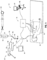
- FIG. 1 illustrates an electromagnetic navigation (EMN) system 10 in accordance with the disclosure.
- ENM electromagnetic navigation
- other tasks that may be performed using the EMN system 10 are planning a pathway to target tissue, navigating a positioning assembly to the target tissue, navigating a catheter 102 to the target tissue to obtain a tissue sample from the target tissue using catheter 102, and digitally marking the location where the tissue sample was obtained, and placing one or more echogenic markers at or around the target.
- EMN system 10 generally includes an operating table 40 configured to support a patient; a bronchoscope 50 configured for insertion through the patient's mouth and/or nose into the patient's airways; monitoring equipment 60 coupled to bronchoscope 50 for displaying video images received from bronchoscope 50; a tracking system 70 including a tracking module 72, a plurality of reference sensors 74, and an electromagnetic field generator 76; a workstation 80 including software and/or hardware used to facilitate pathway planning, identification of target tissue, navigation to target tissue, and digitally marking the biopsy location
- FIG. 1 also depicts two types of catheter guide assemblies 90, 100. Both catheter guide assemblies 90, 100 are usable with the EMN system 10 and share a number of common components.
- Each catheter guide assembly 90, 100 includes a handle 91, which is connected to an extended working channel (EWC) 96.
- the EWC 96 is sized for placement into the working channel of a bronchoscope 50.
- a locatable guide (LG) 92 including an electromagnetic (EM) sensor 94, is inserted into the EWC 96 and locked into position such that the sensor 94 extends a desired distance beyond the distal tip 93 of the EWC 96.
- the location of the EM sensor 94, and thus the distal end of the EWC 96, within an electromagnetic field generated by the electromagnetic field generator 76 can be derived by the tracking module 72, and workstation 80.
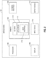
- FIG. 2 illustrates a system diagram of workstation 80.
- Workstation 80 may include memory 202, processor 204, display 206, network interface 208, input device 210, and/or output module 212.
- Workstation 80 implements the methods that will be described herein.
- FIG. 3 depicts a method of navigation using the navigation workstation 80 and the user interface 216.
- user interface 216 presents the clinician with a view (not shown) for the selection of a patient.
- the clinician may enter patient information such as, for example, the patient name or patient ID number, into a text box to select a patient on which to perform a navigation procedure. Alternatively, the patient may be selected from a drop down menu or other similar methods of patient selection.
- the user interface 216 presents the clinician with a view (not shown) including a list of available navigation plans for the selected patient.
- the clinician may load one of the navigation plans by activating the navigation plan.
- the navigation plans may be imported from a procedure planning software and include CT images of the selected patient.
- the user interface 216 presents the clinician with a patient details view (not shown) At step S304 which allows the clinician to review the selected patient and plan details.
- patient details presented to the clinician in the timeout view may include the patient's name, patient ID number, and birth date.
- plan details include navigation plan details, automatic registration status, and/or manual registration status.
- the clinician may activate the navigation plan details to review the navigation plan, and may verify the availability of automatic registration and/or manual registration.
- the clinician may also activate an edit button edit the loaded navigation plan from the patient details view. Activating the edit button of the loaded navigation plan may also activate the planning software described above.
- medical staff may perform the navigation setup prior to or concurrently with the clinician selecting the patient and navigation plan.
- the clinician or other medical staff prepares the patient and operating table by positioning the patient on the operating table over the electromagnetic field generator 76.
- the clinician or other medical staff position reference sensors 74 on the patient's chest and verify that the sensors are properly positioned, for example, through the use of a setup view presented to the clinician or other medical staff by user interface 216.
- Setup view may, for example, provide the clinician or other medical staff with an indication of where the reference sensors 74 are located relative to the magnetic field generated by the electromagnetic field generator 76.
- Patient sensors allow the navigation system to compensate for patient breathing cycles during navigation.
- the clinician also prepares LG 92, EWC 96, and bronchoscope 50 for the procedure by inserting LG 92 into EWC 96 and inserting both LG 92 and EWC 96 into the working channel of bronchoscope 50 such that distal tip 93 of LG 92 extends from the distal end of the working channel of bronchoscope 50.
- the clinician may extend the distal tip 93 of LG 92 10 mm beyond the distal end of the working channel of bronchoscope 50.
- workstation 80 presents a view 400, as shown in FIG. 4 , via the user interface 216.
- CT image data is acquired and displayed at step 308.
- the CT image data is registered with the selected navigation plan.
- An example method for registering images with a navigation plan is described in the aforementioned U.S. Patent Publication No. 2016/0000302 .
- workstation 80 performs a volume rendering algorithm based on the CT image data included in the navigation plan and position signals from sensor 94 to generate a 3D view 404 of the walls of the patient's airways as shown in FIG. 4 .
- the 3D view 404 uses a perspective rendering that supports perception of advancement when moving closer to objects in the volume.
- the 3D view 404 also presents the user with a navigation pathway providing an indication of the direction along which the user will need to travel to reach the lesion 410.
- the navigation pathway may be presented in a color or shape that contrasts with the 3D rendering so that the user may easily determine the desired path to travel.
- Workstation 80 also presents a local view 406 as shown in FIG.
- Local view 406 shows the lesion 410 and the navigation pathway 414 overlaid on slice 416 from an elevated perspective.
- the slice 416 that is presented by local view 406 changes based on the location of EM sensor 94 relative to the 3D volume of the loaded navigation plan.
- Local view 406 also presents the user with a virtual representation of the distal tip 93 of LG 92 in the form of a virtual probe 418.
- the virtual probe 418 provides the user with an indication of the direction that distal tip 93 of LG 92 is facing so that the user can control the advancement of the LG 92 in the patient's airways.
- catheter 102 is navigated through the airways.
- Catheter 102 may be navigated through catheter guide assemblies 90, 100 until catheter 102 approaches the target.
- catheter 102 may be navigated independently of catheter guide assemblies 90, 100.
- Catheter 102 is navigated via manipulation of handle 91 which can be manipulated by rotation and compression.
- steps S314-S316 begin in order to render a 3D volume including locations of one or more airways and one or more targets.
- catheter 102 is further navigated, at step S314, using the 3D volume and locations of one or more airways and one or more targets continually generated in steps S314-S316.
- a view including lungs and lesions is rendered by projecting, from the location and orientation (i.e., the perspective) of catheter 102, parallel beams which accumulate densities until they encounter an opaque object (e.g., bone).
- the volume rendering is performed in two steps: 1) collecting voxel data and 2) accumulating the voxel data in the direction of the beams, which is projected from the location and orientation of catheter 102, until the beam is stopped, at which point the voxel data is added together.
- workstation 80 applies a first transfer function to the volume rendered at step S314.
- the first transfer function is applied to a limited range projected from the position of catheter 102.
- the limited range may be predefined or be dynamically calculated based on a location of and/or distance to the target.
- the first transfer function accumulates voxels which have a density and/or a color within a certain range indicating that the pixel represents a wall of a patient's airways.
- workstation 80 generates a filtered volume rendering preferably showing the patient's airways.
- workstation 80 assesses the result of applying the first transfer function to the rendered volume.
- Workstation 80 may use, for example, image recognition software to determine whether recognizable, airway-shaped elements are visible in the filtered volume rendering.
- the filtered volume rendering may be presented to the clinician such that the clinician may inspect the filtered volume rendering and determine whether airways are visible. The clinician may then indicate on the user interface whether airways are visible. If either workstation 80 or the clinician determines that airways are not visible, the process returns to step S316 wherein the first transfer function is re-applied to the volume rendering with a modified filtering threshold, a modified accumulation of voxels, or a modified projection range. If, at step S316, either workstation 80 or the clinician determines that a requisite number of airways are visible, the process proceeds to step S320.
- workstation 80 applies a second transfer function to the volume rendered at step S314.
- the second transfer function is applied to an unlimited range projected from the position of catheter 102. Though, as a practical matter, it is likely that the projected range will be limited by the size of the rendered volume.
- the second transfer function may also be applied to a limited range projected from the position of catheter 102. Along the range projected from the position of catheter 102, the second transfer function accumulates voxels which have a density and/or a color within a certain range indicating that the pixel represents a target tissue such as a lesion.
- workstation 80 assesses the result of applying the second transfer function to the rendered volume.
- Workstation 80 may use, for example, image recognition software to determine whether recognizable, airway-shaped elements are visible in the filtered volume rendering.
- the filtered volume rendering may be presented to the clinician such that the clinician may inspect the filtered volume rendering and determine whether airways are visible. The clinician may then indicate on the user interface whether target tissue is visible. If either workstation 80 or the clinician determines that target tissue is not visible, the process returns to step S320 wherein the second transfer function is re-applied to the volume rendering with a modified filtering threshold, a modified accumulation of voxels, or a modified projection range. If, at step S322, either workstation 80 or the clinician determines that a target tissue is visible, the process proceeds to step S324.
- Limiting the transfer functions to highlighted structures within the limited range of the distal tip 93 may reduce the load on processor 204.
- denser structures that may obscure the lesion may be omitted permitting the lesion to be displayed.
- the second transfer function may be configured to cause lesions within the range to be displayed in their maximal surface size permitting the user to aim for the center of the target. As shown in alignment view 402, the second transfer functions may be tuned to highlight lesion-density tissue and filter out most other densities in the CT volume, creating a clearer picture in which lung lesions stand out over dark background.
- a marking 408, e.g., a sphere or ellipsoid, may be used to represent the planned target and is overlaid on the rendered volume to reduce risk of aligning to the wrong object.
- a crosshair 415 in the center of the view assists the user in aligning distal tip 93 with the center of the target. The distance 412 from the distal tip 93 to the center of the marked target is displayed next to the crosshair 415, permitting the user to find the best balance between alignment and proximity
- the filtered volume rendering generated by applying the first transfer function and the filtered volume rendering generated by applying the second transfer function are combined in order to generate a display showing the patient's airways and target tissue.
- An example displays resulting from the combination are shown at Fig. 4 .
- the clinician or workstation 80 determines whether the catheter is a located at the target. If the catheter is not located at the target, the process returns to step S314wherein the clinician continues to navigate the catheter toward the target. As the catheter is navigated toward the target, the display volume is continually rendering and the first and the second transfer functions are applied to generate a view showing airways and the target.
- the alignment of catheter 102 using CT image data and 3D models permits a better aiming experience over other CT volume representations.
- Target areas of lesions may be shown from a distance, where a normal CT slice would not be useful.
- the embodiments permit a user to assess optimal balance between alignment/proximity, which defines the best location for catheter introduction.
- the view looks similar to CT images thereby assuring clinicians that the information they are looking at is real, permits aiming to various parts of the lesion structure, and assures users that they are at the planned target.
- irrelevant structures in the range are reduced or eliminated, permitting the user to clearly identify the target.
- Fig. 4 shows 3D view 404 which show walls of the patient's airways.
- the 3D view 404 uses a perspective rendering that supports perception of advancement when moving closer to objects in the volume.
- the 3D view 404 also presents the user with a navigation pathway providing an indication of the direction along which the user will need to travel to reach the lesion 410.
- the navigation pathway may be presented in a color or shape that contrasts with the 3D rendering so that the user may easily determine the desired path to travel.
- Workstation 80 also presents a local view 406 as shown in FIG. 4 that includes a slice of the 3D volume located at and aligned with the distal tip 93 of LG 92.
- Local view 406 shows the lesion 410 and the navigation pathway 414 overlaid on slice 416 from an elevated perspective.
- the slice 416 that is presented by local view 406 changes based on the location of EM sensor 94 relative to the 3D volume of the loaded navigation plan.
- Local view 406 also presents the user with a virtual representation of the distal tip 93 of LG 92 in the form of a virtual probe 418.
- the virtual probe 418 provides the user with an indication of the direction that distal tip 93 of LG 92 is facing so that the user can control the advancement of the LG 92 in the patient's airways.
- catheter guide assemblies 90, 100 have different operating mechanisms, but each contain a handle 91 that can be manipulated by rotation and compression to steer the distal tip 93 of the LG 92, extended working channel 96.
- Catheter guide assemblies 90 are currently marketed and sold by Covidien LP under the name SUPERDIMENSION® Procedure Kits, similarly catheter guide assemblies 100 are currently sold by Covidien LP under the name EDGETM Procedure Kits, both kits include a handle 91, extended working channel 96, and locatable guide 92.
- both kits include a handle 91, extended working channel 96, and locatable guide 92.
- Bronchoscope 50 includes a source of illumination and a video imaging system (not explicitly shown) and is coupled to monitoring equipment 60, e.g., a video display, for displaying the video images received from the video imaging system of bronchoscope 50.
- monitoring equipment 60 e.g., a video display
- Catheter guide assemblies 90, 100 including LG 92 and EWC 96 are configured for insertion through a working channel of bronchoscope 50 into the patient's airways (although the catheter guide assemblies 90, 100 may alternatively be used without bronchoscope 50).
- the LG 92 and EWC 96 are selectively lockable relative to one another via a locking mechanism 99.
- a six degrees-of-freedom electromagnetic tracking system 70 e.g., similar to those disclosed in U.S. Patent No. 6,188,355 and published PCT Application Nos. WO 00/10456 and WO 01/67035 , the entire contents of each of which is incorporated herein by reference, or any other suitable positioning measuring system, is utilized for performing navigation, although other configurations are also contemplated.
- Tracking system 70 is configured for use with catheter guide assemblies 90, 100 to track the position of the EM sensor 94 as it moves in conjunction with the EWC 96 through the airways of the patient, as detailed below.
- electromagnetic field generator 76 is positioned beneath the patient. Electromagnetic field generator 76 and the plurality of reference sensors 74 are interconnected with tracking module 72, which derives the location of each reference sensor 74 in six degrees of freedom. One or more of reference sensors 74 are attached to the chest of the patient. The six degrees of freedom coordinates of reference sensors 74 are sent to workstation 80, which includes application 81 where sensors 74 are used to calculate a patient coordinate frame of reference.
- catheter 102catheter 102 which is insertable into the catheter guide assemblies 90,100 following navigation to a target and removal of the LG 92.
- the catheter 102 is used to collect one or more tissue sample from the target tissue.
- catheter 102 is further configured for use in conjunction with tracking system 70 to facilitate navigation of catheter 102 to the target tissue, tracking of a location of catheter 102 as it is manipulated relative to the target tissue to obtain the tissue sample, and/or marking the location where the tissue sample was obtained.
- EM sensor 94 may be embedded or incorporated within catheter 102 where catheter 102 may alternatively be utilized for navigation without need of the LG or the necessary tool exchanges that use of the LG requires.
- a variety of useable catheters are described in U.S. Patent Publication Nos. 2015/0141869 and 2015/0141809 both entitled DEVICES, SYSTEMS, AND METHODS FOR NAVIGATING A CATHETER TO A TARGET LOCATION AND OBTAINING A TISSUE SAMPLE USING THE SAME, filed November 20, 2013 and U.S. Patent Publication No. 2015/0265257 having the same title and filed March 14, 2014, the entire contents of each of which are incorporated herein by reference and useable with the EMN system 10 as described herein.
- workstation 80 utilizes computed tomographic (CT) image data for generating and viewing a three-dimensional model ("3D model") of the patient's airways, enables the identification of target tissue on the 3D model (automatically, semi-automatically or manually), and allows for the selection of a pathway through the patient's airways to the target tissue. More specifically, the CT scans are processed and assembled into a 3D volume, which is then utilized to generate the 3D model of the patient's airways.
- the 3D model may be presented on a display monitor 81 associated with workstation 80, or in any other suitable fashion.
- various slices of the 3D volume and views of the 3D model may be presented and/or may be manipulated by a clinician to facilitate identification of a target and selection of a suitable pathway through the patient's airways to access the target.
- the 3D model may also show marks of the locations where previous biopsies were performed, including the dates, times, and other identifying information regarding the tissue samples obtained. These marks may also be selected as the target to which a pathway can be planned. Once selected, the pathway is saved for use during the navigation procedure.
- An example of a suitable pathway planning system and method is described in the aforementioned U.S. Patent Nos. 9,459,770 ; and 9,639,666 and U.S. Patent Publication No. 2014/0270441 .
- EM sensor 94 in conjunction with tracking system 70, enables tracking of EM sensor 94 and/or catheter 102 as EM sensor 94 or catheter 102 is advanced through the patient's airways.
- memory 202 includes any non-transitory computer-readable storage media for storing data and/or software that is executable by processor 204 and which controls the operation of workstation 80.
- memory 202 may include one or more solid-state storage devices such as flash memory chips.
- memory 202 may include one or more mass storage devices connected to the processor 204 through a mass storage controller (not shown) and a communications bus (not shown).
- mass storage controller not shown
- communications bus not shown
- computer readable storage media includes non-transitory, volatile and non-volatile, removable and non-removable media implemented in any method or technology for storage of information such as computer-readable instructions, data structures, program modules or other data.
- computer-readable storage media includes RAM, ROM, EPROM, EEPROM, flash memory or other solid state memory technology, CD-ROM, DVD, Blu-Ray or other optical storage, magnetic cassettes, magnetic tape, magnetic disk storage or other magnetic storage devices, or any other medium which can be used to store the desired information and which can be accessed by workstation 80.
- Memory 202 may store application 81 and/or CT data 214.
- Application 81 may, when executed by processor 204, cause display 206 to present user interface 216.
- Network interface 208 may be configured to connect to a network such as a local area network (LAN) consisting of a wired network and/or a wireless network, a wide area network (WAN), a wireless mobile network, a Bluetooth network, and/or the internet.
- Input device 210 may be any device by means of which a user may interact with workstation 80, such as, for example, a mouse, keyboard, foot pedal, touch screen, and/or voice interface.
- Output module 212 may include any connectivity port or bus, such as, for example, parallel ports, serial ports, universal serial busses (USB), or any other similar connectivity port known to those skilled in the art.
- a "Programming Language” and "Computer Program” is any language used to specify instructions to a computer, and includes (but is not limited to) these languages and their derivatives: Assembler, Basic, Batch files, BCPL, C, C+, C++, Delphi, Fortran, Java, JavaScript, Machine code, operating system command languages, Pascal, Perl, PL1, scripting languages, Visual Basic, metalanguages which themselves specify programs, and all first, second, third, fourth, and fifth generation computer languages. Also included are database and other data schemas, and any other meta-languages.
Landscapes
- Health & Medical Sciences (AREA)
- Engineering & Computer Science (AREA)
- Life Sciences & Earth Sciences (AREA)
- Surgery (AREA)
- Nuclear Medicine, Radiotherapy & Molecular Imaging (AREA)
- Public Health (AREA)
- Biomedical Technology (AREA)
- Heart & Thoracic Surgery (AREA)
- Medical Informatics (AREA)
- Molecular Biology (AREA)
- Animal Behavior & Ethology (AREA)
- General Health & Medical Sciences (AREA)
- Veterinary Medicine (AREA)
- Robotics (AREA)
- Human Computer Interaction (AREA)
- Computer Graphics (AREA)
- Physics & Mathematics (AREA)
- General Physics & Mathematics (AREA)
- Theoretical Computer Science (AREA)
- Gynecology & Obstetrics (AREA)
- Radiology & Medical Imaging (AREA)
- Oral & Maxillofacial Surgery (AREA)
- Pathology (AREA)
- Apparatus For Radiation Diagnosis (AREA)
Abstract
Description
- This application claims the benefit of the filing date of provisional
U.S. Patent Application No. 62/628,560, filed February 9, 2018 - Visualization techniques related to visualizing a patient's lungs have been developed so as to help clinicians perform diagnoses and/or surgeries on the patient's lungs. Visualization is especially important for identifying a location of a diseased region. Further, when treating the diseased region, additional emphasis is given to identification of the particular location of the diseased region so that a surgical operation is performed at the correct location.
- The disclosure is directed to a system for navigating a surgical device to a target. The system includes a probe, which includes a location sensor, configured to be navigated through a patient's airways. The system further includes a workstation in operative communication with the probe. The workstation includes a memory and at least one processor. The memory stores a navigation plan and a program that, when executed by the processor, is configured to generate a three-dimensional (3D) rendering of the patient's airways, generate a view using the 3D rendering, and present a user interface that guides a user through the navigation plan, the user interface configured to display the 3D view. To generate the view, the processor executes a first transfer function for a first range from the location sensor to generate one or more airways within the 3D rendering and executes a second transfer function for a second range from the location sensor to generate the one or more targets within the 3D rendering. One or more targets include one or more lesions.
- In an aspect, the first transfer function is executed using a first voxel density, and the second transfer function is executed using a second voxel density. The first and second ranges may include various distances and relationships between the ranges and may be determined at various times and in varying manners. For example, the first range may be less than the second range. As an additional example, at least one of the first range and the second range may be predetermined or dynamically calculated based on a location of the one or more targets.
- In further aspects of the disclosure, the processor is configured to cause further aspects and features to be displayed in the view. In an aspect, the processor is configured to determine intensity associated with the one or more targets and cause the intensity associated with the target to be displayed. Additionally, the one or more targets may be displayed in a maximal surface size in the view.
- In an aspect, the processor is further configured to cause one or more markings to be displayed, for example overlaid, on the one or more targets and to cause a crosshair to be displayed in the view to assist alignment to a center of the one or more targets.
- In yet another aspect of the disclosure a system for navigating to a target is provided. The system includes an electromagnetic tracking system having electromagnetic tracking coordinates, a catheter configured to couple to the electromagnetic tracking system, and a computing device configured to operably coupled to the electromagnetic tracking system and the catheter. The catheter includes a location sensor for detecting a location of the catheter in the electromagnetic tracking coordinates. The computing device is configured to generate a three-dimensional (3D) rendering of a patient's airways, and generate a 3D view by executing a first transfer function for a first range from the location of the catheter to identify one or more airways within the 3D rendering and executing a second transfer function for a second range from the location of the catheter to identify one or more targets within the 3D rendering. In an aspect, the computing device is configured to display the generated 3D view.
- In an aspect, the catheter further includes and a pose sensor for detecting a pose of the catheter in the electromagnetic tracking coordinates.
- In an aspect, at least one of the first range or the second range is dynamically calculated based on the location of the catheter relative to the target.
- In an aspect, the first range is less than the second range.
- In an aspect, the computing device is configured to determine whether a number of the one or more airways within the 3D rendering exceeds a threshold, and execute a modified transfer function to identify one or more airways within the 3D rendering when it is determined that the number of the one or more airways within the 3D rendering does not exceed the threshold. The modified transfer function may include at least one of a modified filtering threshold, a modified accumulation of voxels, or a modified projection range.
- In yet another aspect of the disclosure, a method for navigating to a target is provided. The method includes generating a three-dimensional (3D) rendering of a patient's lungs, executing a first transfer function for a first range from a location of a probe within the patient's lungs to identify one or more airways within the 3D rendering, executing a second transfer function for a second range from the location of the probe to identify one or more targets within the 3D rendering, and generating a 3D view based on the first transfer function and the second transfer function.
- In an aspect, the method further includes displaying the 3D view.
- In an aspect, the first range is less than the second range.
- In an aspect, the method further includes determining whether a number of the one or more airways within the 3D rendering exceeds a threshold and executing a modified transfer function to identify one or more airways within the 3D rendering when it is determined that the number of the one or more airways within the 3D rendering does not exceed the threshold. In an aspect, executing the modified transfer function includes at least one of modifying a filtering threshold, modifying an accumulation of voxels, or modifying a projection range.
- Any of the above aspects and embodiments of the disclosure may be combined without departing from the scope of the disclosure.
- Various aspects and features of the disclosure are described hereinbelow with references to the drawings, wherein:
-
FIG. 1 is a perspective view of an electromagnetic navigation system in accordance with the disclosure; -
FIG. 2 is a schematic diagram of a workstation configured for use with the system ofFIG. 1 ; -
FIG. 3 is a flow chart illustrating a method of navigation in accordance with an embodiment of the disclosure; and -
FIG. 4 is an illustration of a user interface of the workstation ofFIG. 2 presenting a view for performing registration in accordance with the disclosure. - The disclosure relates to systems and methods for internally guided navigation of catheters based on a model generated from CT image data.
- In the past, scanned two-dimensional (2D) images of the lungs have been used to aid in visualization. In order to obtain the 2D images, a patient undergoes a CT scans. In addition to using scanned 2D images, three-dimensional (3D) models may also be used to virtually navigate through the body. The use of 3D models for navigation is more complex than using 2D images and includes several challenges. One challenge involves guiding a catheter to the target in 3D. Many views have been developed, some of them using cross-sections, and a proposed view is designed to assist with guidance. However, when one tries to look through the whole volume from a point of view instead of looking at a cross-section, the view may be obstructed and objects, which are behind other objects, might not be seen. Methods have been developed to alleviate the obstructed view problem, such as adding transparency to some of the volume or highlighting farther objects. One of the known methods involves Maximum Intensity Projection (MIP) which is a volume rendering method for 3D data that projects in the visualization plane the voxels with maximum intensity that fall in the way of parallel rays traced from the viewpoint to the plane of projection.
- However, when using MIP to align an electromagnetic navigation catheter towards a lesion, traditional methods may result in lesions located beyond objects, such as bones or other non-soft tissue, not being visible. Therefore, there is a need to develop new view development techniques that improve upon MIP.
- The disclosure is related to devices, systems, and methods for internally guided navigation of catheters based on a model generated from CT image data to guide a catheter to a target. In the disclosure, the system provides a view of a defined section of a volume from the perspective of the catheter. To achieve the view disclosed in the current application, two filters are separately applied to a rendered 3D volume. The filters isolate airway tissue and lesion tissue from the 3D rendering so that it can be combined in order to generate a view which presents only airways and lesions and eliminates obstacles such as bones which would ordinarily obscure a view from the catheter.
- Alignment of
catheter 102 may be a necessary component of pathway planning for performing an ELECTROMAGNETIC NAVIGATION BRONCHOSCOPY® (ENB) procedure using an electromagnetic navigation (EMN) system. An ENB procedure generally involves at least two phases: (1) planning a pathway to a target located within, or adjacent to, the patient's lungs; and (2) navigating a probe to the target along the planned pathway. These phases are generally referred to as (1) "planning" and (2) "navigation." The planning phase of an ENB procedure is more fully described in commonly-ownedU.S. Patent Nos. 9,459,770 9,639,666 U.S. Patent Publication No. 2014/0270441 , all entitled "Pathway Planning System and Method," filed on March 15, 2013, by Baker, the entire contents of which are hereby incorporated by reference. An example of the navigation software can be found in commonly assignedU.S. Patent Publication No. 2016/0000302 entitled "SYSTEM AND METHOD FOR NAVIGATING WITHIN THE LUNG" the entire contents of which are incorporated herein by reference. - Prior to the planning phase, the patient's lungs are imaged by, for example, a computed tomography (CT) scan, although additional applicable methods of imaging will be known to those skilled in the art. The image data assembled during the CT scan may then be stored in, for example, the Digital Imaging and Communications in Medicine (DICOM) format, although additional applicable formats will be known to those skilled in the art. The CT scan image data may then be loaded into a planning software application ("application") to be used during the planning phase of the ENB procedure.
- Embodiments of the systems and methods are described with reference to the accompanying drawings. Like reference numerals may refer to similar or identical elements throughout the description of the figures. This description may use the phrases "in an embodiment," "in embodiments," "in some embodiments," or "in other embodiments," which may each refer to one or more of the same or different embodiments in accordance with the disclosure.
-
FIG. 1 illustrates an electromagnetic navigation (EMN)system 10 in accordance with the disclosure. Among other tasks that may be performed using theEMN system 10 are planning a pathway to target tissue, navigating a positioning assembly to the target tissue, navigating acatheter 102 to the target tissue to obtain a tissue sample from the targettissue using catheter 102, and digitally marking the location where the tissue sample was obtained, and placing one or more echogenic markers at or around the target. -
EMN system 10 generally includes an operating table 40 configured to support a patient; abronchoscope 50 configured for insertion through the patient's mouth and/or nose into the patient's airways; monitoringequipment 60 coupled tobronchoscope 50 for displaying video images received frombronchoscope 50; atracking system 70 including atracking module 72, a plurality ofreference sensors 74, and anelectromagnetic field generator 76; aworkstation 80 including software and/or hardware used to facilitate pathway planning, identification of target tissue, navigation to target tissue, and digitally marking the biopsy location -
FIG. 1 also depicts two types ofcatheter guide assemblies 90, 100. Bothcatheter guide assemblies 90, 100 are usable with theEMN system 10 and share a number of common components. Eachcatheter guide assembly 90, 100 includes ahandle 91, which is connected to an extended working channel (EWC) 96. TheEWC 96 is sized for placement into the working channel of abronchoscope 50. In operation, a locatable guide (LG) 92, including an electromagnetic (EM)sensor 94, is inserted into theEWC 96 and locked into position such that thesensor 94 extends a desired distance beyond thedistal tip 93 of theEWC 96. The location of theEM sensor 94, and thus the distal end of theEWC 96, within an electromagnetic field generated by theelectromagnetic field generator 76 can be derived by thetracking module 72, andworkstation 80. -
FIG. 2 illustrates a system diagram ofworkstation 80.Workstation 80 may includememory 202,processor 204,display 206,network interface 208,input device 210, and/oroutput module 212.Workstation 80 implements the methods that will be described herein. -
FIG. 3 depicts a method of navigation using thenavigation workstation 80 and theuser interface 216. At stepS300 user interface 216 presents the clinician with a view (not shown) for the selection of a patient. The clinician may enter patient information such as, for example, the patient name or patient ID number, into a text box to select a patient on which to perform a navigation procedure. Alternatively, the patient may be selected from a drop down menu or other similar methods of patient selection. Once the patient has been selected, theuser interface 216 presents the clinician with a view (not shown) including a list of available navigation plans for the selected patient. At step S302, the clinician may load one of the navigation plans by activating the navigation plan. The navigation plans may be imported from a procedure planning software and include CT images of the selected patient. - Once the patient has been selected and a corresponding navigation plan has been loaded, the
user interface 216 presents the clinician with a patient details view (not shown) At step S304 which allows the clinician to review the selected patient and plan details. Examples of patient details presented to the clinician in the timeout view may include the patient's name, patient ID number, and birth date. Examples of plan details include navigation plan details, automatic registration status, and/or manual registration status. For example, the clinician may activate the navigation plan details to review the navigation plan, and may verify the availability of automatic registration and/or manual registration. The clinician may also activate an edit button edit the loaded navigation plan from the patient details view. Activating the edit button of the loaded navigation plan may also activate the planning software described above. Once the clinician is satisfied that the patient and plan details are correct, the clinician proceeds to navigation setup at step S306. Alternatively, medical staff may perform the navigation setup prior to or concurrently with the clinician selecting the patient and navigation plan. - During navigation setup at step S306, the clinician or other medical staff prepares the patient and operating table by positioning the patient on the operating table over the
electromagnetic field generator 76. The clinician or other medical staffposition reference sensors 74 on the patient's chest and verify that the sensors are properly positioned, for example, through the use of a setup view presented to the clinician or other medical staff byuser interface 216. Setup view may, for example, provide the clinician or other medical staff with an indication of where thereference sensors 74 are located relative to the magnetic field generated by theelectromagnetic field generator 76. Patient sensors allow the navigation system to compensate for patient breathing cycles during navigation. The clinician also preparesLG 92,EWC 96, andbronchoscope 50 for the procedure by insertingLG 92 intoEWC 96 and inserting bothLG 92 andEWC 96 into the working channel ofbronchoscope 50 such thatdistal tip 93 ofLG 92 extends from the distal end of the working channel ofbronchoscope 50. For example, the clinician may extend thedistal tip 93 ofLG 92 10 mm beyond the distal end of the working channel ofbronchoscope 50. - Once setup is complete,
workstation 80 presents aview 400, as shown inFIG. 4 , via theuser interface 216. CT image data is acquired and displayed atstep 308. Atstep 310, the CT image data is registered with the selected navigation plan. An example method for registering images with a navigation plan is described in the aforementionedU.S. Patent Publication No. 2016/0000302 . - At step S312,
workstation 80 performs a volume rendering algorithm based on the CT image data included in the navigation plan and position signals fromsensor 94 to generate a3D view 404 of the walls of the patient's airways as shown inFIG. 4 . The3D view 404 uses a perspective rendering that supports perception of advancement when moving closer to objects in the volume. The3D view 404 also presents the user with a navigation pathway providing an indication of the direction along which the user will need to travel to reach thelesion 410. The navigation pathway may be presented in a color or shape that contrasts with the 3D rendering so that the user may easily determine the desired path to travel.Workstation 80 also presents alocal view 406 as shown inFIG. 4 that includes a slice of the 3D volume located at and aligned with thedistal tip 93 ofLG 92.Local view 406 shows thelesion 410 and thenavigation pathway 414 overlaid onslice 416 from an elevated perspective. Theslice 416 that is presented bylocal view 406 changes based on the location ofEM sensor 94 relative to the 3D volume of the loaded navigation plan.Local view 406 also presents the user with a virtual representation of thedistal tip 93 ofLG 92 in the form of avirtual probe 418. Thevirtual probe 418 provides the user with an indication of the direction thatdistal tip 93 ofLG 92 is facing so that the user can control the advancement of theLG 92 in the patient's airways. - At step S314,
catheter 102 is navigated through the airways.Catheter 102 may be navigated throughcatheter guide assemblies 90, 100 untilcatheter 102 approaches the target. Alternatively,catheter 102 may be navigated independently ofcatheter guide assemblies 90, 100.Catheter 102 is navigated via manipulation ofhandle 91 which can be manipulated by rotation and compression. Oncecatheter 102 is located approximate the target, steps S314-S316 begin in order to render a 3D volume including locations of one or more airways and one or more targets. Untilcatheter 102 is located at the target,catheter 102 is further navigated, at step S314, using the 3D volume and locations of one or more airways and one or more targets continually generated in steps S314-S316. - At steps S316 and S320, a view including lungs and lesions is rendered by projecting, from the location and orientation (i.e., the perspective) of
catheter 102, parallel beams which accumulate densities until they encounter an opaque object (e.g., bone). The volume rendering is performed in two steps: 1) collecting voxel data and 2) accumulating the voxel data in the direction of the beams, which is projected from the location and orientation ofcatheter 102, until the beam is stopped, at which point the voxel data is added together. - Further at step S316,
workstation 80 applies a first transfer function to the volume rendered at step S314. The first transfer function is applied to a limited range projected from the position ofcatheter 102. The limited range may be predefined or be dynamically calculated based on a location of and/or distance to the target. Along the limited range projected from the position ofcatheter 102, the first transfer function accumulates voxels which have a density and/or a color within a certain range indicating that the pixel represents a wall of a patient's airways. As a result of applying the first transfer function,workstation 80 generates a filtered volume rendering preferably showing the patient's airways. - Further at step S318,
workstation 80 assesses the result of applying the first transfer function to the rendered volume.Workstation 80 may use, for example, image recognition software to determine whether recognizable, airway-shaped elements are visible in the filtered volume rendering. Alternatively, the filtered volume rendering may be presented to the clinician such that the clinician may inspect the filtered volume rendering and determine whether airways are visible. The clinician may then indicate on the user interface whether airways are visible. If eitherworkstation 80 or the clinician determines that airways are not visible, the process returns to step S316 wherein the first transfer function is re-applied to the volume rendering with a modified filtering threshold, a modified accumulation of voxels, or a modified projection range. If, at step S316, eitherworkstation 80 or the clinician determines that a requisite number of airways are visible, the process proceeds to step S320. - At step S320,
workstation 80 applies a second transfer function to the volume rendered at step S314. The second transfer function is applied to an unlimited range projected from the position ofcatheter 102. Though, as a practical matter, it is likely that the projected range will be limited by the size of the rendered volume. The second transfer function may also be applied to a limited range projected from the position ofcatheter 102. Along the range projected from the position ofcatheter 102, the second transfer function accumulates voxels which have a density and/or a color within a certain range indicating that the pixel represents a target tissue such as a lesion. Applying the second transfer function to an unlimited range from the position ofcatheter 102 allows voxels representing target tissue such as a lesion to be detected and shown beyond opaque objects (e.g., bones). As a result of applying the second transfer function to the rendered volume,workstation 80 generates a filtered volume rendering preferably showing target tissues, including those located beyond bones and other opaque objects. - At steps S322,
workstation 80 assesses the result of applying the second transfer function to the rendered volume.Workstation 80 may use, for example, image recognition software to determine whether recognizable, airway-shaped elements are visible in the filtered volume rendering. Alternatively, the filtered volume rendering may be presented to the clinician such that the clinician may inspect the filtered volume rendering and determine whether airways are visible. The clinician may then indicate on the user interface whether target tissue is visible. If eitherworkstation 80 or the clinician determines that target tissue is not visible, the process returns to step S320 wherein the second transfer function is re-applied to the volume rendering with a modified filtering threshold, a modified accumulation of voxels, or a modified projection range. If, at step S322, eitherworkstation 80 or the clinician determines that a target tissue is visible, the process proceeds to step S324. - Limiting the transfer functions to highlighted structures within the limited range of the
distal tip 93 may reduce the load onprocessor 204. By using a limited range, denser structures that may obscure the lesion may be omitted permitting the lesion to be displayed. The second transfer function may be configured to cause lesions within the range to be displayed in their maximal surface size permitting the user to aim for the center of the target. As shown inalignment view 402, the second transfer functions may be tuned to highlight lesion-density tissue and filter out most other densities in the CT volume, creating a clearer picture in which lung lesions stand out over dark background. A marking 408, e.g., a sphere or ellipsoid, may be used to represent the planned target and is overlaid on the rendered volume to reduce risk of aligning to the wrong object. Acrosshair 415 in the center of the view assists the user in aligningdistal tip 93 with the center of the target. Thedistance 412 from thedistal tip 93 to the center of the marked target is displayed next to thecrosshair 415, permitting the user to find the best balance between alignment and proximity - At step S324, the filtered volume rendering generated by applying the first transfer function and the filtered volume rendering generated by applying the second transfer function are combined in order to generate a display showing the patient's airways and target tissue. An example displays resulting from the combination are shown at
Fig. 4 . - At step S326, the clinician or
workstation 80 determines whether the catheter is a located at the target. If the catheter is not located at the target, the process returns to step S314wherein the clinician continues to navigate the catheter toward the target. As the catheter is navigated toward the target, the display volume is continually rendering and the first and the second transfer functions are applied to generate a view showing airways and the target. - In the embodiments, the alignment of
catheter 102 using CT image data and 3D models permits a better aiming experience over other CT volume representations. Target areas of lesions may be shown from a distance, where a normal CT slice would not be useful. The embodiments permit a user to assess optimal balance between alignment/proximity, which defines the best location for catheter introduction. The view looks similar to CT images thereby assuring clinicians that the information they are looking at is real, permits aiming to various parts of the lesion structure, and assures users that they are at the planned target. In the 3D models, irrelevant structures in the range are reduced or eliminated, permitting the user to clearly identify the target. -
Fig. 4 shows3D view 404 which show walls of the patient's airways. The3D view 404 uses a perspective rendering that supports perception of advancement when moving closer to objects in the volume. The3D view 404 also presents the user with a navigation pathway providing an indication of the direction along which the user will need to travel to reach thelesion 410. The navigation pathway may be presented in a color or shape that contrasts with the 3D rendering so that the user may easily determine the desired path to travel.Workstation 80 also presents alocal view 406 as shown inFIG. 4 that includes a slice of the 3D volume located at and aligned with thedistal tip 93 ofLG 92.Local view 406 shows thelesion 410 and thenavigation pathway 414 overlaid onslice 416 from an elevated perspective. Theslice 416 that is presented bylocal view 406 changes based on the location ofEM sensor 94 relative to the 3D volume of the loaded navigation plan.Local view 406 also presents the user with a virtual representation of thedistal tip 93 ofLG 92 in the form of avirtual probe 418. Thevirtual probe 418 provides the user with an indication of the direction thatdistal tip 93 ofLG 92 is facing so that the user can control the advancement of theLG 92 in the patient's airways. - Referring back to
FIG. 1 ,catheter guide assemblies 90, 100 have different operating mechanisms, but each contain ahandle 91 that can be manipulated by rotation and compression to steer thedistal tip 93 of theLG 92, extended workingchannel 96.Catheter guide assemblies 90 are currently marketed and sold by Covidien LP under the name SUPERDIMENSION® Procedure Kits, similarly catheter guide assemblies 100 are currently sold by Covidien LP under the name EDGE™ Procedure Kits, both kits include ahandle 91, extended workingchannel 96, andlocatable guide 92. For a more detailed description of thecatheter guide assemblies 90, 100 reference is made to commonly-ownedU.S. Patent Application Serial No. 13/836,203 filed on March 15, 2013 by Ladtkow et al. - In
FIG. 1 , the patient is shown lying on operating table 40 withbronchoscope 50 inserted through the patient's mouth and into the patient's airways.Bronchoscope 50 includes a source of illumination and a video imaging system (not explicitly shown) and is coupled tomonitoring equipment 60, e.g., a video display, for displaying the video images received from the video imaging system ofbronchoscope 50. -
Catheter guide assemblies 90, 100 includingLG 92 andEWC 96 are configured for insertion through a working channel ofbronchoscope 50 into the patient's airways (although thecatheter guide assemblies 90, 100 may alternatively be used without bronchoscope 50). TheLG 92 andEWC 96 are selectively lockable relative to one another via alocking mechanism 99. A six degrees-of-freedomelectromagnetic tracking system 70, e.g., similar to those disclosed inU.S. Patent No. 6,188,355 and publishedPCT Application Nos. WO 00/10456 WO 01/67035 Tracking system 70 is configured for use withcatheter guide assemblies 90, 100 to track the position of theEM sensor 94 as it moves in conjunction with theEWC 96 through the airways of the patient, as detailed below. - As shown in
FIG. 1 ,electromagnetic field generator 76 is positioned beneath the patient.Electromagnetic field generator 76 and the plurality ofreference sensors 74 are interconnected withtracking module 72, which derives the location of eachreference sensor 74 in six degrees of freedom. One or more ofreference sensors 74 are attached to the chest of the patient. The six degrees of freedom coordinates ofreference sensors 74 are sent toworkstation 80, which includesapplication 81 wheresensors 74 are used to calculate a patient coordinate frame of reference. - Also shown in
FIG. 1 iscatheter 102catheter 102 which is insertable into the catheter guide assemblies 90,100 following navigation to a target and removal of theLG 92. Thecatheter 102 is used to collect one or more tissue sample from the target tissue. As detailed below,catheter 102 is further configured for use in conjunction with trackingsystem 70 to facilitate navigation ofcatheter 102 to the target tissue, tracking of a location ofcatheter 102 as it is manipulated relative to the target tissue to obtain the tissue sample, and/or marking the location where the tissue sample was obtained. - Although navigation is detailed above with respect to
EM sensor 94 being included in theLG 92 it is also envisioned thatEM sensor 94 may be embedded or incorporated withincatheter 102 wherecatheter 102 may alternatively be utilized for navigation without need of the LG or the necessary tool exchanges that use of the LG requires. A variety of useable catheters are described inU.S. Patent Publication Nos. 2015/0141869 and2015/0141809 both entitled DEVICES, SYSTEMS, AND METHODS FOR NAVIGATING A CATHETER TO A TARGET LOCATION AND OBTAINING A TISSUE SAMPLE USING THE SAME, filed November 20, 2013 andU.S. Patent Publication No. 2015/0265257 having the same title and filed March 14, 2014, the entire contents of each of which are incorporated herein by reference and useable with theEMN system 10 as described herein. - During procedure planning,
workstation 80 utilizes computed tomographic (CT) image data for generating and viewing a three-dimensional model ("3D model") of the patient's airways, enables the identification of target tissue on the 3D model (automatically, semi-automatically or manually), and allows for the selection of a pathway through the patient's airways to the target tissue. More specifically, the CT scans are processed and assembled into a 3D volume, which is then utilized to generate the 3D model of the patient's airways. The 3D model may be presented on adisplay monitor 81 associated withworkstation 80, or in any other suitable fashion. Usingworkstation 80, various slices of the 3D volume and views of the 3D model may be presented and/or may be manipulated by a clinician to facilitate identification of a target and selection of a suitable pathway through the patient's airways to access the target. The 3D model may also show marks of the locations where previous biopsies were performed, including the dates, times, and other identifying information regarding the tissue samples obtained. These marks may also be selected as the target to which a pathway can be planned. Once selected, the pathway is saved for use during the navigation procedure. An example of a suitable pathway planning system and method is described in the aforementionedU.S. Patent Nos. 9,459,770 9,639,666 U.S. Patent Publication No. 2014/0270441 . - During navigation,
EM sensor 94, in conjunction with trackingsystem 70, enables tracking ofEM sensor 94 and/orcatheter 102 asEM sensor 94 orcatheter 102 is advanced through the patient's airways. - Referring back to
FIG. 2 ,memory 202 includes any non-transitory computer-readable storage media for storing data and/or software that is executable byprocessor 204 and which controls the operation ofworkstation 80. In an embodiment,memory 202 may include one or more solid-state storage devices such as flash memory chips. Alternatively or in addition to the one or more solid-state storage devices,memory 202 may include one or more mass storage devices connected to theprocessor 204 through a mass storage controller (not shown) and a communications bus (not shown). Although the description of computer-readable media contained herein refers to a solid-state storage, it should be appreciated by those skilled in the art that computer-readable storage media can be any available media that can be accessed by theprocessor 204. That is, computer readable storage media includes non-transitory, volatile and non-volatile, removable and non-removable media implemented in any method or technology for storage of information such as computer-readable instructions, data structures, program modules or other data. For example, computer-readable storage media includes RAM, ROM, EPROM, EEPROM, flash memory or other solid state memory technology, CD-ROM, DVD, Blu-Ray or other optical storage, magnetic cassettes, magnetic tape, magnetic disk storage or other magnetic storage devices, or any other medium which can be used to store the desired information and which can be accessed byworkstation 80. -
Memory 202 may storeapplication 81 and/orCT data 214.Application 81 may, when executed byprocessor 204,cause display 206 to presentuser interface 216.Network interface 208 may be configured to connect to a network such as a local area network (LAN) consisting of a wired network and/or a wireless network, a wide area network (WAN), a wireless mobile network, a Bluetooth network, and/or the internet.Input device 210 may be any device by means of which a user may interact withworkstation 80, such as, for example, a mouse, keyboard, foot pedal, touch screen, and/or voice interface.Output module 212 may include any connectivity port or bus, such as, for example, parallel ports, serial ports, universal serial busses (USB), or any other similar connectivity port known to those skilled in the art. - Any of the described methods, programs, algorithms or codes may be converted to, or expressed in, a programming language or computer program. A "Programming Language" and "Computer Program" is any language used to specify instructions to a computer, and includes (but is not limited to) these languages and their derivatives: Assembler, Basic, Batch files, BCPL, C, C+, C++, Delphi, Fortran, Java, JavaScript, Machine code, operating system command languages, Pascal, Perl, PL1, scripting languages, Visual Basic, metalanguages which themselves specify programs, and all first, second, third, fourth, and fifth generation computer languages. Also included are database and other data schemas, and any other meta-languages. For the purposes of this definition, no distinction is made between languages which are interpreted, compiled, or use both compiled and interpreted approaches. For the purposes of this definition, no distinction is made between compiled and source versions of a program. Thus, reference to a program, where the programming language could exist in more than one state (such as source, compiled, object, or linked) is a reference to any and all such states. The definition also encompasses the actual instructions and the intent of those instructions.
- Although embodiments have been described in detail with reference to the accompanying drawings for the purpose of illustration and description, it is to be understood that the inventive processes and apparatus are not to be construed as limited thereby. It will be apparent to those of ordinary skill in the art that various modifications to the foregoing embodiments may be made without departing from the scope of the disclosure.
- The invention may be described by reference to the following numbered paragraphs:-
- 1. A system for navigating to a target, the system comprising:
- a probe configured to be navigated through a patient's airways, the probe including a location sensor and a pose sensor, the location sensor configured to generate location information of the probe and the pose sensor configured to generate pose information of the probe; and
- a workstation in operative communication with the probe, the workstation including a memory and at least one processor, the memory storing a navigation plan and a program that, when executed by the processor, is configured to:
- generate a three-dimensional (3D) rendering of the patient's airways,
- receive the location information and the pose information;
- generate a view using the 3D rendering by executing a first transfer function for a first range from the location sensor to identify one or more airways within the 3D rendering and executing a second transfer function for a second range from the location sensor to identify one or more targets within the 3D rendering; and
- cause the view to be displayed featuring at least a portion of the navigation plan.
- 2. The system according to paragraph 1, wherein the first transfer function is executed using a first voxel density, and the second transfer function is executed using a second voxel density.
- 3. The system according to paragraph 1, wherein the first range is less than the second range.
- 4. The system according to paragraph 1, wherein at least one of the first range and the second range is predetermined.
- 5. The system according to paragraph 1, wherein at least one of the first range and the second range is dynamically calculated based on a location of the one or more targets.
- 6. The system according to paragraph 1, wherein the one or more targets include one or more lesions.
- 7. The system according to paragraph 1, wherein the view includes a mark overlaid on the one or more targets.
- 8. The system according to paragraph 1, wherein the view includes a crosshair to assist alignment to a center of the one or more targets.
- 9. A system for navigating to a target, the system comprising:
- an electromagnetic tracking system having electromagnetic tracking coordinates;
- a catheter configured to couple to the electromagnetic tracking system, the catheter including a location sensor for detecting a location of the catheter in the electromagnetic tracking coordinates; and
- a computing device configured to operably couple to the electromagnetic tracking system and the catheter, the computing device configured to:
- generate a three-dimensional (3D) rendering of a patient's airways; and
- generate a 3D view by executing a first transfer function for a first range from the location of the catheter to identify one or more airways within the 3D rendering and executing a second transfer function for a second range from the location of the catheter to identify one or more targets within the 3D rendering.
- 10. The system according to paragraph 9, wherein the catheter includes and a pose sensor for detecting a pose of the catheter in the electromagnetic tracking coordinates.
- 11. The system according to paragraph 9, wherein the computing device is configured to display the generated 3D view.
- 12. The system according to paragraph 9, wherein at least one of the first range or the second range is dynamically calculated based on the location of the catheter relative to the target.
- 13. The system according to paragraph 9, wherein the first range is less than the second range.
- 14. The system according to paragraph 9, wherein the computing device is configured to:
- determine whether a number of the one or more airways within the 3D rendering exceeds a threshold; and
- execute a modified transfer function to identify one or more airways within the 3D rendering when it is determined that the number of the one or more airways within the 3D rendering does not exceed the threshold.
- 15. The system according to paragraph 14, wherein the modified transfer function includes at least one of a modified filtering threshold, a modified accumulation of voxels, or a modified projection range.
- 16. A method for navigating to a target, the method comprising:
- generating a three-dimensional (3D) rendering of a patient's lungs;
- executing a first transfer function for a first range from a location of a probe within the patient's lungs to identify one or more airways within the 3D rendering;
- executing a second transfer function for a second range from the location of the probe to identify one or more targets within the 3D rendering; and
- generating a 3D view based on the first transfer function and the second transfer function.
- 17. The method according to paragraph 16, further comprising displaying the 3D view.
- 18. The method according to paragraph 16, wherein the first range is less than the second range.
- 19. The method according to paragraph 16, further comprising:
- determining whether a number of the one or more airways within the 3D rendering exceeds a threshold; and
- executing a modified transfer function to identify one or more airways within the 3D rendering when it is determined that the number of the one or more airways within the 3D rendering does not exceed the threshold.
- 20. The method according to paragraph 19, wherein executing the modified transfer function includes at least one of modifying a filtering threshold, modifying an accumulation of voxels, or modifying a projection range.
Claims (15)
- A system for navigating to a target, the system comprising:a probe configured to be navigated through a patient's airways, the probe including a location sensor and a pose sensor, the location sensor configured to generate location information of the probe and the pose sensor configured to generate pose information of the probe; anda workstation in operative communication with the probe, the workstation including a memory and at least one processor, the memory storing a navigation plan and a program that, when executed by the processor, is configured to:generate a three-dimensional (3D) rendering of the patient's airways,receive the location information and the pose information;generate a view using the 3D rendering by executing a first transfer function for a first range from the location sensor to identify one or more airways within the 3D rendering and executing a second transfer function for a second range from the location sensor to identify one or more targets within the 3D rendering; andcause the view to be displayed featuring at least a portion of the navigation plan.
- The system according to claim 1, wherein the first transfer function is executed using a first voxel density, and the second transfer function is executed using a second voxel density; and/or wherein the first range is less than the second range.
- The system according to claim 1 or claim 2, wherein at least one of the first range and the second range is predetermined; and/or wherein at least one of the first range and the second range is dynamically calculated based on a location of the one or more targets.
- The system according to any preceding claim, wherein the one or more targets include one or more lesions.
- The system according to any preceding claim, wherein the view includes a mark overlaid on the one or more targets; and/or wherein the view includes a crosshair to assist alignment to a center of the one or more targets.
- A system for navigating to a target, the system comprising:an electromagnetic tracking system having electromagnetic tracking coordinates;a catheter configured to couple to the electromagnetic tracking system, the catheter including a location sensor for detecting a location of the catheter in the electromagnetic tracking coordinates; anda computing device configured to operably couple to the electromagnetic tracking system and the catheter, the computing device configured to:generate a three-dimensional (3D) rendering of a patient's airways; andgenerate a 3D view by executing a first transfer function for a first range from the location of the catheter to identify one or more airways within the 3D rendering and executing a second transfer function for a second range from the location of the catheter to identify one or more targets within the 3D rendering.
- The system according to claim 6, wherein the catheter includes and a pose sensor for detecting a pose of the catheter in the electromagnetic tracking coordinates; and/or wherein the computing device is configured to display the generated 3D view.
- The system according to claim 6 or claim 7, wherein at least one of the first range or the second range is dynamically calculated based on the location of the catheter relative to the target.
- The system according to any of claims 6 to 8, wherein the first range is less than the second range.
- The system according to any of claims 6 to 9, wherein the computing device is configured to:determine whether a number of the one or more airways within the 3D rendering exceeds a threshold; andexecute a modified transfer function to identify one or more airways within the 3D rendering when it is determined that the number of the one or more airways within the 3D rendering does not exceed the threshold; preferably wherein the modified transfer function includes at least one of a modified filtering threshold, a modified accumulation of voxels, or a modified projection range.
- A method for navigating to a target, the method comprising:generating a three-dimensional (3D) rendering of a patient's lungs;executing a first transfer function for a first range from a location of a probe within the patient's lungs to identify one or more airways within the 3D rendering;executing a second transfer function for a second range from the location of the probe to identify one or more targets within the 3D rendering; andgenerating a 3D view based on the first transfer function and the second transfer function.
- The method according to claim 11, further comprising displaying the 3D view.
- The method according to claim 12, wherein the first range is less than the second range.
- The method according to claim 12 or claim 13, further comprising:determining whether a number of the one or more airways within the 3D rendering exceeds a threshold; andexecuting a modified transfer function to identify one or more airways within the 3D rendering when it is determined that the number of the one or more airways within the 3D rendering does not exceed the threshold.
- The method according to claim 14, wherein executing the modified transfer function includes at least one of modifying a filtering threshold, modifying an accumulation of voxels, or modifying a projection range.
Applications Claiming Priority (2)
| Application Number | Priority Date | Filing Date | Title |
|---|---|---|---|
| US201862628560P | 2018-02-09 | 2018-02-09 | |
| US16/264,817 US11464576B2 (en) | 2018-02-09 | 2019-02-01 | System and method for displaying an alignment CT |
Publications (2)
| Publication Number | Publication Date |
|---|---|
| EP3525174A1 true EP3525174A1 (en) | 2019-08-14 |
| EP3525174B1 EP3525174B1 (en) | 2021-01-06 |
Family
ID=65576110
Family Applications (1)
| Application Number | Title | Priority Date | Filing Date |
|---|---|---|---|
| EP19156249.5A Active EP3525174B1 (en) | 2018-02-09 | 2019-02-08 | System and method for displaying an alignment ct |
Country Status (3)
| Country | Link |
|---|---|
| US (3) | US11464576B2 (en) |
| EP (1) | EP3525174B1 (en) |
| CN (1) | CN210301211U (en) |
Citations (14)
| Publication number | Priority date | Publication date | Assignee | Title |
|---|---|---|---|---|
| WO2000010456A1 (en) | 1998-08-02 | 2000-03-02 | Super Dimension Ltd. | Intrabody navigation system for medical applications |
| US6188355B1 (en) | 1997-12-12 | 2001-02-13 | Super Dimension Ltd. | Wireless six-degree-of-freedom locator |
| WO2001067035A1 (en) | 2000-03-09 | 2001-09-13 | Super Dimension Ltd. | Object tracking using a single sensor or a pair of sensors |
| DE102009007360A1 (en) * | 2009-02-04 | 2010-08-12 | Siemens Aktiengesellschaft | Method for visualizing oxygen supply blockade points and/or areas in lungs of patient during treatment of chronic obstructive pulmonary disease, involves stopping supply of oxygen to target partial areas of organ with blockade points |
| US8150111B2 (en) * | 2005-03-15 | 2012-04-03 | The University Of North Carolina At Chapel Hill | Methods, systems, and computer program products for processing three-dimensional image data to render an image from a viewpoint within or beyond an occluding region of the image data |
| US20140270441A1 (en) | 2013-03-15 | 2014-09-18 | Covidien Lp | Pathway planning system and method |
| US20150141809A1 (en) | 2013-11-20 | 2015-05-21 | Covidien Lp | Devices, systems, and methods for navigating a biopsy tool to a target location and obtaining a tissue sample using the same |
| US20150141869A1 (en) | 2013-11-20 | 2015-05-21 | Covidien Lp | Devices, systems, and methods for navigating a biopsy tool to a target location and obtaining a tissue sample using the same |
| US20150265257A1 (en) | 2014-03-19 | 2015-09-24 | Covidien Lp | Devices, systems, and methods for navigating a biopsy tool to a target location and obtaining a tissue sample using the same |
| US20160000303A1 (en) * | 2014-07-02 | 2016-01-07 | Covidien Lp | Alignment ct |
| US20160000302A1 (en) | 2014-07-02 | 2016-01-07 | Covidien Lp | System and method for navigating within the lung |
| US9459770B2 (en) | 2013-03-15 | 2016-10-04 | Covidien Lp | Pathway planning system and method |
| US20170084027A1 (en) * | 2015-09-18 | 2017-03-23 | Auris Surgical Robotics, Inc. | Navigation of tubular networks |
| US9639666B2 (en) | 2013-03-15 | 2017-05-02 | Covidien Lp | Pathway planning system and method |
Family Cites Families (90)
| Publication number | Priority date | Publication date | Assignee | Title |
|---|---|---|---|---|
| US5542915A (en) | 1992-08-12 | 1996-08-06 | Vidamed, Inc. | Thermal mapping catheter with ultrasound probe |
| US5237647A (en) | 1989-09-15 | 1993-08-17 | Massachusetts Institute Of Technology | Computer aided drawing in three dimensions |
| US5227985A (en) | 1991-08-19 | 1993-07-13 | University Of Maryland | Computer vision system for position monitoring in three dimensions using non-coplanar light sources attached to a monitored object |
| US5364392A (en) | 1993-05-14 | 1994-11-15 | Fidus Medical Technology Corporation | Microwave ablation catheter system with impedance matching tuner and method |
| US5297061A (en) | 1993-05-19 | 1994-03-22 | University Of Maryland | Three dimensional pointing device monitored by computer vision |
| US6575969B1 (en) | 1995-05-04 | 2003-06-10 | Sherwood Services Ag | Cool-tip radiofrequency thermosurgery electrode system for tumor ablation |
| US6689127B1 (en) | 1995-08-15 | 2004-02-10 | Rita Medical Systems | Multiple antenna ablation apparatus and method with multiple sensor feedback |
| US5995107A (en) | 1996-08-02 | 1999-11-30 | Autodesk, Inc. | Caching in a three dimensional modeling and animation system |
| EP0926629A1 (en) | 1997-01-24 | 1999-06-30 | Sony Corporation | Pattern data generator, pattern data generating method and its medium |
| SE519310C2 (en) | 1997-10-02 | 2003-02-11 | Prostalund Operations Ab | Device for heat supply |
| US6427089B1 (en) | 1999-02-19 | 2002-07-30 | Edward W. Knowlton | Stomach treatment apparatus and method |
| US6346938B1 (en) | 1999-04-27 | 2002-02-12 | Harris Corporation | Computer-resident mechanism for manipulating, navigating through and mensurating displayed image of three-dimensional geometric model |
| US6373916B1 (en) | 1999-05-10 | 2002-04-16 | Shimadzu Corporation | X-ray CT apparatus |
| US9833167B2 (en) | 1999-05-18 | 2017-12-05 | Mediguide Ltd. | Method and system for superimposing virtual anatomical landmarks on an image |
| US7097641B1 (en) | 1999-12-09 | 2006-08-29 | Cryocath Technologies Inc. | Catheter with cryogenic and heating ablation |
| US6942661B2 (en) | 2000-08-30 | 2005-09-13 | Boston Scientific Scimed, Inc. | Fluid cooled apparatus for supporting diagnostic and therapeutic elements in contact with tissue |
| US6473634B1 (en) | 2000-11-22 | 2002-10-29 | Koninklijke Philips Electronics N.V. | Medical imaging at two temporal resolutions for tumor treatment planning |
| ITPI20010006A1 (en) | 2001-01-31 | 2002-07-31 | Cnr Consiglio Naz Delle Ricer | INTERSTITIAL ANTENNA WITH MINIATURIZED CHOKE FOR MICROWAVE HYPERTEMIA APPLICATIONS IN MEDICINE AND SURGERY |
| US6549802B2 (en) | 2001-06-07 | 2003-04-15 | Varian Medical Systems, Inc. | Seed localization system and method in ultrasound by fluoroscopy and ultrasound fusion |
| EP3189781A1 (en) | 2002-04-17 | 2017-07-12 | Covidien LP | Endoscope structures and techniques for navigating to a target in branched structure |
| US7998062B2 (en) | 2004-03-29 | 2011-08-16 | Superdimension, Ltd. | Endoscope structures and techniques for navigating to a target in branched structure |
| US7825667B2 (en) * | 2003-04-04 | 2010-11-02 | Microwave Imaging Systems Technologies, Inc. | Microwave imaging system and processes, and associated software products |
| US7822461B2 (en) * | 2003-07-11 | 2010-10-26 | Siemens Medical Solutions Usa, Inc. | System and method for endoscopic path planning |
| US7379769B2 (en) | 2003-09-30 | 2008-05-27 | Sunnybrook Health Sciences Center | Hybrid imaging method to monitor medical device delivery and patient support for use in the method |
| WO2005058137A2 (en) | 2003-12-12 | 2005-06-30 | University Of Washington | Catheterscope 3d guidance and interface system |
| US20050245920A1 (en) | 2004-04-30 | 2005-11-03 | Vitullo Jeffrey M | Cell necrosis apparatus with cooled microwave antenna |
| WO2006017172A1 (en) | 2004-07-09 | 2006-02-16 | Fischer Imaging Corporation | Diagnostic system for multimodality mammography |
| JP4208791B2 (en) | 2004-08-11 | 2009-01-14 | キヤノン株式会社 | Image processing apparatus, control method therefor, and program |
| US20060116576A1 (en) * | 2004-12-01 | 2006-06-01 | Scimed Life Systems, Inc. | System and use thereof to provide indication of proximity between catheter and location of interest in 3-D space |
| US7551759B2 (en) | 2004-12-07 | 2009-06-23 | Siemens Medical Solutions Usa, Inc. | Target identification using time-based data sets |
| JP2006198107A (en) | 2005-01-19 | 2006-08-03 | Olympus Corp | Surgery support system |
| JP4914574B2 (en) | 2005-04-18 | 2012-04-11 | オリンパスメディカルシステムズ株式会社 | Endoscope shape detection device |
| US8712115B2 (en) | 2005-04-19 | 2014-04-29 | Siemens Medical Solutions Usa, Inc. | Real-time virtual endoscopy |
| US7397890B2 (en) | 2005-04-25 | 2008-07-08 | Xoran Technologies, Inc. | CT system with synthetic view generation |
| US20070167714A1 (en) | 2005-12-07 | 2007-07-19 | Siemens Corporate Research, Inc. | System and Method For Bronchoscopic Navigational Assistance |
| US20070238981A1 (en) * | 2006-03-13 | 2007-10-11 | Bracco Imaging Spa | Methods and apparatuses for recording and reviewing surgical navigation processes |
| EP3797721A1 (en) | 2006-03-24 | 2021-03-31 | Neuwave Medical, Inc. | Transmission line with heat transfer ability |
| US20070257903A1 (en) | 2006-05-04 | 2007-11-08 | Harris Corporation | Geographic information system (gis) for displaying 3d geospatial images with reference markers and related methods |
| US20070288207A1 (en) | 2006-06-12 | 2007-12-13 | Autodesk, Inc. | Displaying characteristics of a system of interconnected components at different system locations |
| WO2008017051A2 (en) | 2006-08-02 | 2008-02-07 | Inneroptic Technology Inc. | System and method of providing real-time dynamic imagery of a medical procedure site using multiple modalities |
| JP2008054763A (en) | 2006-08-29 | 2008-03-13 | Hitachi Medical Corp | Medical diagnostic imaging equipment |
| US8672836B2 (en) | 2007-01-31 | 2014-03-18 | The Penn State Research Foundation | Method and apparatus for continuous guidance of endoscopy |
| WO2008111070A2 (en) | 2007-03-12 | 2008-09-18 | David Tolkowsky | Devices and methods for performing medical procedures in tree-like luminal structures |
| IL184151A0 (en) | 2007-06-21 | 2007-10-31 | Diagnostica Imaging Software Ltd | X-ray measurement method |
| JP4388104B2 (en) | 2007-06-29 | 2009-12-24 | ザイオソフト株式会社 | Image processing method, image processing program, and image processing apparatus |
| US20090012390A1 (en) | 2007-07-02 | 2009-01-08 | General Electric Company | System and method to improve illustration of an object with respect to an imaged subject |
| JP5263867B2 (en) | 2007-10-15 | 2013-08-14 | ジーイー・メディカル・システムズ・グローバル・テクノロジー・カンパニー・エルエルシー | Ultrasonic imaging device |
| US8219179B2 (en) | 2008-03-06 | 2012-07-10 | Vida Diagnostics, Inc. | Systems and methods for navigation within a branched structure of a body |
| JP5865702B2 (en) | 2008-04-03 | 2016-02-17 | メドトロニック, インク.Medtronic, Inc. | System and method for hyperthermia treatment |
| US8218846B2 (en) | 2008-05-15 | 2012-07-10 | Superdimension, Ltd. | Automatic pathway and waypoint generation and navigation method |
| US8641621B2 (en) | 2009-02-17 | 2014-02-04 | Inneroptic Technology, Inc. | Systems, methods, apparatuses, and computer-readable media for image management in image-guided medical procedures |
| US8690776B2 (en) | 2009-02-17 | 2014-04-08 | Inneroptic Technology, Inc. | Systems, methods, apparatuses, and computer-readable media for image guided surgery |
| WO2010144402A2 (en) | 2009-06-08 | 2010-12-16 | Surgivision, Inc. | Mri-guided surgical systems with preset scan planes |
| US8551083B2 (en) | 2009-11-17 | 2013-10-08 | Bsd Medical Corporation | Microwave coagulation applicator and system |
| US9993294B2 (en) | 2009-11-17 | 2018-06-12 | Perseon Corporation | Microwave coagulation applicator and system with fluid injection |
| CN102740755B (en) | 2010-02-22 | 2015-04-22 | 奥林巴斯医疗株式会社 | Medical device |
| US8625869B2 (en) | 2010-05-21 | 2014-01-07 | Siemens Medical Solutions Usa, Inc. | Visualization of medical image data with localized enhancement |
| US10165928B2 (en) | 2010-08-20 | 2019-01-01 | Mark Hunter | Systems, instruments, and methods for four dimensional soft tissue navigation |
| EP2642913B1 (en) | 2010-11-27 | 2024-02-21 | Boston Scientific Scimed, Inc. | Ablation and temperature measurement devices |
| US20120232549A1 (en) | 2011-03-09 | 2012-09-13 | Vivant Medical, Inc. | Systems for thermal-feedback-controlled rate of fluid flow to fluid-cooled antenna assembly and methods of directing energy to tissue using same |
| US9572539B2 (en) | 2011-04-08 | 2017-02-21 | Imactis | Device and method for determining the position of an instrument in relation to medical images |
| JP5763263B2 (en) | 2011-04-08 | 2015-08-12 | コビディエン エルピー | Flexible microwave catheter for natural or artificial lumens |
| IN2014CN04517A (en) | 2011-12-03 | 2015-09-11 | Koninkl Philips Nv | |
| US8920368B2 (en) | 2011-12-22 | 2014-12-30 | St. Jude Medical, Atrial Fibrillation Division, Inc. | Multi-user touch-based control of a remote catheter guidance system (RCGS) |
| US8670816B2 (en) | 2012-01-30 | 2014-03-11 | Inneroptic Technology, Inc. | Multiple medical device guidance |
| EP2816966B1 (en) | 2012-02-22 | 2023-10-25 | Veran Medical Technologies, Inc. | Steerable surgical catheter comprising a biopsy device at the distal end portion thereof |
| US9044254B2 (en) | 2012-08-07 | 2015-06-02 | Covidien Lp | Microwave ablation catheter and method of utilizing the same |
| CN106562757B (en) | 2012-08-14 | 2019-05-14 | 直观外科手术操作公司 | The system and method for registration for multiple vision systems |
| US20140088457A1 (en) | 2012-09-26 | 2014-03-27 | Covidien Lp | Bleeding containment device |
| US20140135744A1 (en) | 2012-11-09 | 2014-05-15 | Orthosensor Inc | Motion and orientation sensing module or device for positioning of implants |
| US20140188440A1 (en) | 2012-12-31 | 2014-07-03 | Intuitive Surgical Operations, Inc. | Systems And Methods For Interventional Procedure Planning |
| US20140267031A1 (en) | 2013-03-12 | 2014-09-18 | Kenneth J. Huebner | Spatially aware pointer for mobile appliances |
| US9301723B2 (en) | 2013-03-15 | 2016-04-05 | Covidien Lp | Microwave energy-delivery device and system |
| WO2014145058A1 (en) | 2013-03-15 | 2014-09-18 | Lantos Technologies, Inc. | Scanning techniques for probing and measuring anatomical cavities |
| US9158431B2 (en) | 2013-05-29 | 2015-10-13 | Intergraph Corporation | Apparatus and method for manipulating the orientation of an object on a display device |
| CN105101879B (en) | 2014-01-07 | 2019-04-30 | 东芝医疗系统株式会社 | X-ray CT apparatus and CT image display method |
| JP6359312B2 (en) | 2014-03-27 | 2018-07-18 | キヤノンメディカルシステムズ株式会社 | X-ray diagnostic equipment |
| US20150305650A1 (en) | 2014-04-23 | 2015-10-29 | Mark Hunter | Apparatuses and methods for endobronchial navigation to and confirmation of the location of a target tissue and percutaneous interception of the target tissue |
| JP6604977B2 (en) | 2014-07-02 | 2019-11-13 | コヴィディエン リミテッド パートナーシップ | System that provides distance and orientation feedback during 3D navigation |
| US9754367B2 (en) | 2014-07-02 | 2017-09-05 | Covidien Lp | Trachea marking |
| JP6514724B2 (en) | 2014-07-02 | 2019-05-15 | コヴィディエン リミテッド パートナーシップ | Integrated coordinate system for multiple CT scans of patient lungs |
| US9603668B2 (en) * | 2014-07-02 | 2017-03-28 | Covidien Lp | Dynamic 3D lung map view for tool navigation inside the lung |
| US11188285B2 (en) | 2014-07-02 | 2021-11-30 | Covidien Lp | Intelligent display |
| AU2015283946B2 (en) | 2014-07-02 | 2019-09-12 | Covidien Lp | Real-time automatic registration feedback |
| EP3164072B1 (en) | 2014-07-02 | 2020-04-08 | Covidien LP | System and method for segmentation of lung |
| US20160000414A1 (en) | 2014-07-02 | 2016-01-07 | Covidien Lp | Methods for marking biopsy location |
| CA2946615A1 (en) | 2014-07-02 | 2016-01-07 | Covidien Lp | System and method for detecting trachea |
| US9633431B2 (en) | 2014-07-02 | 2017-04-25 | Covidien Lp | Fluoroscopic pose estimation |
| US10896506B2 (en) | 2016-02-12 | 2021-01-19 | Intuitive Surgical Operations, Inc | Systems and methods for using registered fluoroscopic images in image-guided surgery |
| WO2017153839A1 (en) | 2016-03-10 | 2017-09-14 | Body Vision Medical Ltd. | Methods and systems for using multi view pose estimation |
-
2019
- 2019-02-01 US US16/264,817 patent/US11464576B2/en active Active
- 2019-02-08 EP EP19156249.5A patent/EP3525174B1/en active Active
- 2019-02-11 CN CN201920189478.1U patent/CN210301211U/en active Active
-
2022
- 2022-10-11 US US17/963,416 patent/US11857276B2/en active Active
-
2023
- 2023-10-26 US US18/384,261 patent/US20240050167A1/en not_active Abandoned
Patent Citations (14)
| Publication number | Priority date | Publication date | Assignee | Title |
|---|---|---|---|---|
| US6188355B1 (en) | 1997-12-12 | 2001-02-13 | Super Dimension Ltd. | Wireless six-degree-of-freedom locator |
| WO2000010456A1 (en) | 1998-08-02 | 2000-03-02 | Super Dimension Ltd. | Intrabody navigation system for medical applications |
| WO2001067035A1 (en) | 2000-03-09 | 2001-09-13 | Super Dimension Ltd. | Object tracking using a single sensor or a pair of sensors |
| US8150111B2 (en) * | 2005-03-15 | 2012-04-03 | The University Of North Carolina At Chapel Hill | Methods, systems, and computer program products for processing three-dimensional image data to render an image from a viewpoint within or beyond an occluding region of the image data |
| DE102009007360A1 (en) * | 2009-02-04 | 2010-08-12 | Siemens Aktiengesellschaft | Method for visualizing oxygen supply blockade points and/or areas in lungs of patient during treatment of chronic obstructive pulmonary disease, involves stopping supply of oxygen to target partial areas of organ with blockade points |
| US9459770B2 (en) | 2013-03-15 | 2016-10-04 | Covidien Lp | Pathway planning system and method |
| US20140270441A1 (en) | 2013-03-15 | 2014-09-18 | Covidien Lp | Pathway planning system and method |
| US9639666B2 (en) | 2013-03-15 | 2017-05-02 | Covidien Lp | Pathway planning system and method |
| US20150141809A1 (en) | 2013-11-20 | 2015-05-21 | Covidien Lp | Devices, systems, and methods for navigating a biopsy tool to a target location and obtaining a tissue sample using the same |
| US20150141869A1 (en) | 2013-11-20 | 2015-05-21 | Covidien Lp | Devices, systems, and methods for navigating a biopsy tool to a target location and obtaining a tissue sample using the same |
| US20150265257A1 (en) | 2014-03-19 | 2015-09-24 | Covidien Lp | Devices, systems, and methods for navigating a biopsy tool to a target location and obtaining a tissue sample using the same |
| US20160000303A1 (en) * | 2014-07-02 | 2016-01-07 | Covidien Lp | Alignment ct |
| US20160000302A1 (en) | 2014-07-02 | 2016-01-07 | Covidien Lp | System and method for navigating within the lung |
| US20170084027A1 (en) * | 2015-09-18 | 2017-03-23 | Auris Surgical Robotics, Inc. | Navigation of tubular networks |
Also Published As
| Publication number | Publication date |
|---|---|
| US11857276B2 (en) | 2024-01-02 |
| CN210301211U (en) | 2020-04-14 |
| US20190247125A1 (en) | 2019-08-15 |
| US20230106560A1 (en) | 2023-04-06 |
| US20240050167A1 (en) | 2024-02-15 |
| EP3525174B1 (en) | 2021-01-06 |
| US11464576B2 (en) | 2022-10-11 |
Similar Documents
| Publication | Publication Date | Title |
|---|---|---|
| US11844635B2 (en) | Alignment CT | |
| US11576556B2 (en) | System and method for navigating within the lung | |
| US11798178B2 (en) | Fluoroscopic pose estimation | |
| US11172989B2 (en) | Dynamic 3D lung map view for tool navigation inside the lung | |
| EP3689285A1 (en) | Systems and methods for visualizing navigation of medical devices relative to targets | |
| AU2018290995A1 (en) | System and method for identifying, marking and navigating to a target using real-time two-dimensional fluoroscopic data | |
| EP3689244B1 (en) | Method for displaying tumor location within endoscopic images | |
| US11857276B2 (en) | System and method for displaying an alignment CT | |
| EP4346613B1 (en) | Volumetric filter of fluoroscopic sweep video |
Legal Events
| Date | Code | Title | Description |
|---|---|---|---|
| PUAI | Public reference made under article 153(3) epc to a published international application that has entered the european phase |
Free format text: ORIGINAL CODE: 0009012 |
|
| STAA | Information on the status of an ep patent application or granted ep patent |
Free format text: STATUS: REQUEST FOR EXAMINATION WAS MADE |
|
| 17P | Request for examination filed |
Effective date: 20190208 |
|
| AK | Designated contracting states |
Kind code of ref document: A1 Designated state(s): AL AT BE BG CH CY CZ DE DK EE ES FI FR GB GR HR HU IE IS IT LI LT LU LV MC MK MT NL NO PL PT RO RS SE SI SK SM TR |
|
| AX | Request for extension of the european patent |
Extension state: BA ME |
|
| RIN1 | Information on inventor provided before grant (corrected) |
Inventor name: WEINGARTEN, OREN P. Inventor name: KLEIN, EYAL |
|
| RBV | Designated contracting states (corrected) |
Designated state(s): AL AT BE BG CH CY CZ DE DK EE ES FI FR GB GR HR HU IE IS IT LI LT LU LV MC MK MT NL NO PL PT RO RS SE SI SK SM TR |
|
| GRAP | Despatch of communication of intention to grant a patent |
Free format text: ORIGINAL CODE: EPIDOSNIGR1 |
|
| STAA | Information on the status of an ep patent application or granted ep patent |
Free format text: STATUS: GRANT OF PATENT IS INTENDED |
|
| RIC1 | Information provided on ipc code assigned before grant |
Ipc: A61B 17/00 20060101ALN20200707BHEP Ipc: A61B 34/00 20160101ALI20200707BHEP Ipc: A61B 90/00 20160101ALN20200707BHEP Ipc: A61B 34/20 20160101ALN20200707BHEP Ipc: G06T 15/00 20110101AFI20200707BHEP Ipc: A61B 10/02 20060101ALN20200707BHEP |
|
| RIC1 | Information provided on ipc code assigned before grant |
Ipc: A61B 10/02 20060101ALN20200714BHEP Ipc: G06T 15/00 20110101AFI20200714BHEP Ipc: A61B 34/20 20160101ALN20200714BHEP Ipc: A61B 34/00 20160101ALI20200714BHEP Ipc: A61B 90/00 20160101ALN20200714BHEP Ipc: A61B 17/00 20060101ALN20200714BHEP |
|
| INTG | Intention to grant announced |
Effective date: 20200730 |
|
| GRAS | Grant fee paid |
Free format text: ORIGINAL CODE: EPIDOSNIGR3 |
|
| GRAA | (expected) grant |
Free format text: ORIGINAL CODE: 0009210 |
|
| STAA | Information on the status of an ep patent application or granted ep patent |
Free format text: STATUS: THE PATENT HAS BEEN GRANTED |
|
| AK | Designated contracting states |
Kind code of ref document: B1 Designated state(s): AL AT BE BG CH CY CZ DE DK EE ES FI FR GB GR HR HU IE IS IT LI LT LU LV MC MK MT NL NO PL PT RO RS SE SI SK SM TR |
|
| REG | Reference to a national code |
Ref country code: GB Ref legal event code: FG4D |
|
| REG | Reference to a national code |
Ref country code: AT Ref legal event code: REF Ref document number: 1353175 Country of ref document: AT Kind code of ref document: T Effective date: 20210115 Ref country code: CH Ref legal event code: EP |
|
| REG | Reference to a national code |
Ref country code: DE Ref legal event code: R096 Ref document number: 602019002014 Country of ref document: DE |
|
| REG | Reference to a national code |
Ref country code: IE Ref legal event code: FG4D |
|
| REG | Reference to a national code |
Ref country code: DE Ref legal event code: R082 Ref document number: 602019002014 Country of ref document: DE Representative=s name: WR SERVICES GMBH, DE |
|
| REG | Reference to a national code |
Ref country code: NL Ref legal event code: MP Effective date: 20210106 |
|
| REG | Reference to a national code |
Ref country code: AT Ref legal event code: MK05 Ref document number: 1353175 Country of ref document: AT Kind code of ref document: T Effective date: 20210106 |
|
| REG | Reference to a national code |
Ref country code: LT Ref legal event code: MG9D |
|
| PG25 | Lapsed in a contracting state [announced via postgrant information from national office to epo] |
Ref country code: BG Free format text: LAPSE BECAUSE OF FAILURE TO SUBMIT A TRANSLATION OF THE DESCRIPTION OR TO PAY THE FEE WITHIN THE PRESCRIBED TIME-LIMIT Effective date: 20210406 Ref country code: HR Free format text: LAPSE BECAUSE OF FAILURE TO SUBMIT A TRANSLATION OF THE DESCRIPTION OR TO PAY THE FEE WITHIN THE PRESCRIBED TIME-LIMIT Effective date: 20210106 Ref country code: GR Free format text: LAPSE BECAUSE OF FAILURE TO SUBMIT A TRANSLATION OF THE DESCRIPTION OR TO PAY THE FEE WITHIN THE PRESCRIBED TIME-LIMIT Effective date: 20210407 Ref country code: FI Free format text: LAPSE BECAUSE OF FAILURE TO SUBMIT A TRANSLATION OF THE DESCRIPTION OR TO PAY THE FEE WITHIN THE PRESCRIBED TIME-LIMIT Effective date: 20210106 Ref country code: NO Free format text: LAPSE BECAUSE OF FAILURE TO SUBMIT A TRANSLATION OF THE DESCRIPTION OR TO PAY THE FEE WITHIN THE PRESCRIBED TIME-LIMIT Effective date: 20210406 Ref country code: PT Free format text: LAPSE BECAUSE OF FAILURE TO SUBMIT A TRANSLATION OF THE DESCRIPTION OR TO PAY THE FEE WITHIN THE PRESCRIBED TIME-LIMIT Effective date: 20210506 Ref country code: LT Free format text: LAPSE BECAUSE OF FAILURE TO SUBMIT A TRANSLATION OF THE DESCRIPTION OR TO PAY THE FEE WITHIN THE PRESCRIBED TIME-LIMIT Effective date: 20210106 |
|
| PG25 | Lapsed in a contracting state [announced via postgrant information from national office to epo] |
Ref country code: AT Free format text: LAPSE BECAUSE OF FAILURE TO SUBMIT A TRANSLATION OF THE DESCRIPTION OR TO PAY THE FEE WITHIN THE PRESCRIBED TIME-LIMIT Effective date: 20210106 Ref country code: LV Free format text: LAPSE BECAUSE OF FAILURE TO SUBMIT A TRANSLATION OF THE DESCRIPTION OR TO PAY THE FEE WITHIN THE PRESCRIBED TIME-LIMIT Effective date: 20210106 Ref country code: PL Free format text: LAPSE BECAUSE OF FAILURE TO SUBMIT A TRANSLATION OF THE DESCRIPTION OR TO PAY THE FEE WITHIN THE PRESCRIBED TIME-LIMIT Effective date: 20210106 Ref country code: RS Free format text: LAPSE BECAUSE OF FAILURE TO SUBMIT A TRANSLATION OF THE DESCRIPTION OR TO PAY THE FEE WITHIN THE PRESCRIBED TIME-LIMIT Effective date: 20210106 Ref country code: SE Free format text: LAPSE BECAUSE OF FAILURE TO SUBMIT A TRANSLATION OF THE DESCRIPTION OR TO PAY THE FEE WITHIN THE PRESCRIBED TIME-LIMIT Effective date: 20210106 |
|
| PG25 | Lapsed in a contracting state [announced via postgrant information from national office to epo] |
Ref country code: IS Free format text: LAPSE BECAUSE OF FAILURE TO SUBMIT A TRANSLATION OF THE DESCRIPTION OR TO PAY THE FEE WITHIN THE PRESCRIBED TIME-LIMIT Effective date: 20210506 |
|
| REG | Reference to a national code |
Ref country code: DE Ref legal event code: R097 Ref document number: 602019002014 Country of ref document: DE |
|
| REG | Reference to a national code |
Ref country code: BE Ref legal event code: MM Effective date: 20210228 |
|
| PG25 | Lapsed in a contracting state [announced via postgrant information from national office to epo] |
Ref country code: CZ Free format text: LAPSE BECAUSE OF FAILURE TO SUBMIT A TRANSLATION OF THE DESCRIPTION OR TO PAY THE FEE WITHIN THE PRESCRIBED TIME-LIMIT Effective date: 20210106 Ref country code: EE Free format text: LAPSE BECAUSE OF FAILURE TO SUBMIT A TRANSLATION OF THE DESCRIPTION OR TO PAY THE FEE WITHIN THE PRESCRIBED TIME-LIMIT Effective date: 20210106 Ref country code: MC Free format text: LAPSE BECAUSE OF FAILURE TO SUBMIT A TRANSLATION OF THE DESCRIPTION OR TO PAY THE FEE WITHIN THE PRESCRIBED TIME-LIMIT Effective date: 20210106 Ref country code: LU Free format text: LAPSE BECAUSE OF NON-PAYMENT OF DUE FEES Effective date: 20210208 Ref country code: SM Free format text: LAPSE BECAUSE OF FAILURE TO SUBMIT A TRANSLATION OF THE DESCRIPTION OR TO PAY THE FEE WITHIN THE PRESCRIBED TIME-LIMIT Effective date: 20210106 |
|
| PLBE | No opposition filed within time limit |
Free format text: ORIGINAL CODE: 0009261 |
|
| STAA | Information on the status of an ep patent application or granted ep patent |
Free format text: STATUS: NO OPPOSITION FILED WITHIN TIME LIMIT |
|
| PG25 | Lapsed in a contracting state [announced via postgrant information from national office to epo] |
Ref country code: DK Free format text: LAPSE BECAUSE OF FAILURE TO SUBMIT A TRANSLATION OF THE DESCRIPTION OR TO PAY THE FEE WITHIN THE PRESCRIBED TIME-LIMIT Effective date: 20210106 Ref country code: RO Free format text: LAPSE BECAUSE OF FAILURE TO SUBMIT A TRANSLATION OF THE DESCRIPTION OR TO PAY THE FEE WITHIN THE PRESCRIBED TIME-LIMIT Effective date: 20210106 Ref country code: SK Free format text: LAPSE BECAUSE OF FAILURE TO SUBMIT A TRANSLATION OF THE DESCRIPTION OR TO PAY THE FEE WITHIN THE PRESCRIBED TIME-LIMIT Effective date: 20210106 |
|
| 26N | No opposition filed |
Effective date: 20211007 |
|
| PG25 | Lapsed in a contracting state [announced via postgrant information from national office to epo] |
Ref country code: AL Free format text: LAPSE BECAUSE OF FAILURE TO SUBMIT A TRANSLATION OF THE DESCRIPTION OR TO PAY THE FEE WITHIN THE PRESCRIBED TIME-LIMIT Effective date: 20210106 Ref country code: IE Free format text: LAPSE BECAUSE OF NON-PAYMENT OF DUE FEES Effective date: 20210208 Ref country code: ES Free format text: LAPSE BECAUSE OF FAILURE TO SUBMIT A TRANSLATION OF THE DESCRIPTION OR TO PAY THE FEE WITHIN THE PRESCRIBED TIME-LIMIT Effective date: 20210106 |
|
| PG25 | Lapsed in a contracting state [announced via postgrant information from national office to epo] |
Ref country code: SI Free format text: LAPSE BECAUSE OF FAILURE TO SUBMIT A TRANSLATION OF THE DESCRIPTION OR TO PAY THE FEE WITHIN THE PRESCRIBED TIME-LIMIT Effective date: 20210106 |
|
| PG25 | Lapsed in a contracting state [announced via postgrant information from national office to epo] |
Ref country code: IT Free format text: LAPSE BECAUSE OF FAILURE TO SUBMIT A TRANSLATION OF THE DESCRIPTION OR TO PAY THE FEE WITHIN THE PRESCRIBED TIME-LIMIT Effective date: 20210106 |
|
| PG25 | Lapsed in a contracting state [announced via postgrant information from national office to epo] |
Ref country code: IS Free format text: LAPSE BECAUSE OF FAILURE TO SUBMIT A TRANSLATION OF THE DESCRIPTION OR TO PAY THE FEE WITHIN THE PRESCRIBED TIME-LIMIT Effective date: 20210506 |
|
| PG25 | Lapsed in a contracting state [announced via postgrant information from national office to epo] |
Ref country code: BE Free format text: LAPSE BECAUSE OF NON-PAYMENT OF DUE FEES Effective date: 20210228 |
|
| REG | Reference to a national code |
Ref country code: CH Ref legal event code: PL |
|
| PG25 | Lapsed in a contracting state [announced via postgrant information from national office to epo] |
Ref country code: LI Free format text: LAPSE BECAUSE OF NON-PAYMENT OF DUE FEES Effective date: 20220228 Ref country code: CH Free format text: LAPSE BECAUSE OF NON-PAYMENT OF DUE FEES Effective date: 20220228 |
|
| PG25 | Lapsed in a contracting state [announced via postgrant information from national office to epo] |
Ref country code: NL Free format text: LAPSE BECAUSE OF NON-PAYMENT OF DUE FEES Effective date: 20210206 Ref country code: CY Free format text: LAPSE BECAUSE OF FAILURE TO SUBMIT A TRANSLATION OF THE DESCRIPTION OR TO PAY THE FEE WITHIN THE PRESCRIBED TIME-LIMIT Effective date: 20210106 |
|
| PG25 | Lapsed in a contracting state [announced via postgrant information from national office to epo] |
Ref country code: HU Free format text: LAPSE BECAUSE OF FAILURE TO SUBMIT A TRANSLATION OF THE DESCRIPTION OR TO PAY THE FEE WITHIN THE PRESCRIBED TIME-LIMIT; INVALID AB INITIO Effective date: 20190208 |
|
| PG25 | Lapsed in a contracting state [announced via postgrant information from national office to epo] |
Ref country code: MK Free format text: LAPSE BECAUSE OF FAILURE TO SUBMIT A TRANSLATION OF THE DESCRIPTION OR TO PAY THE FEE WITHIN THE PRESCRIBED TIME-LIMIT Effective date: 20210106 |
|
| PG25 | Lapsed in a contracting state [announced via postgrant information from national office to epo] |
Ref country code: TR Free format text: LAPSE BECAUSE OF FAILURE TO SUBMIT A TRANSLATION OF THE DESCRIPTION OR TO PAY THE FEE WITHIN THE PRESCRIBED TIME-LIMIT Effective date: 20210106 |
|
| PG25 | Lapsed in a contracting state [announced via postgrant information from national office to epo] |
Ref country code: MT Free format text: LAPSE BECAUSE OF FAILURE TO SUBMIT A TRANSLATION OF THE DESCRIPTION OR TO PAY THE FEE WITHIN THE PRESCRIBED TIME-LIMIT Effective date: 20210106 |
|
| PGFP | Annual fee paid to national office [announced via postgrant information from national office to epo] |
Ref country code: GB Payment date: 20260121 Year of fee payment: 8 |
|
| PGFP | Annual fee paid to national office [announced via postgrant information from national office to epo] |
Ref country code: DE Payment date: 20260121 Year of fee payment: 8 |
|
| PGFP | Annual fee paid to national office [announced via postgrant information from national office to epo] |
Ref country code: FR Payment date: 20260121 Year of fee payment: 8 |