EP3525082A1 - Operation terminal, method of controlling operations of the same, and output system - Google Patents
Operation terminal, method of controlling operations of the same, and output system Download PDFInfo
- Publication number
- EP3525082A1 EP3525082A1 EP19158005.9A EP19158005A EP3525082A1 EP 3525082 A1 EP3525082 A1 EP 3525082A1 EP 19158005 A EP19158005 A EP 19158005A EP 3525082 A1 EP3525082 A1 EP 3525082A1
- Authority
- EP
- European Patent Office
- Prior art keywords
- file
- information storage
- storage apparatus
- operation terminal
- information
- Prior art date
- Legal status (The legal status is an assumption and is not a legal conclusion. Google has not performed a legal analysis and makes no representation as to the accuracy of the status listed.)
- Pending
Links
Images


Classifications
-
- G—PHYSICS
- G06—COMPUTING; CALCULATING OR COUNTING
- G06F—ELECTRIC DIGITAL DATA PROCESSING
- G06F3/00—Input arrangements for transferring data to be processed into a form capable of being handled by the computer; Output arrangements for transferring data from processing unit to output unit, e.g. interface arrangements
- G06F3/12—Digital output to print unit, e.g. line printer, chain printer
- G06F3/1293—Printer information exchange with computer
-
- H—ELECTRICITY
- H04—ELECTRIC COMMUNICATION TECHNIQUE
- H04N—PICTORIAL COMMUNICATION, e.g. TELEVISION
- H04N1/00—Scanning, transmission or reproduction of documents or the like, e.g. facsimile transmission; Details thereof
- H04N1/00002—Diagnosis, testing or measuring; Detecting, analysing or monitoring not otherwise provided for
- H04N1/00007—Diagnosis, testing or measuring; Detecting, analysing or monitoring not otherwise provided for relating to particular apparatus or devices
- H04N1/0001—Transmission systems or arrangements
-
- G—PHYSICS
- G06—COMPUTING; CALCULATING OR COUNTING
- G06F—ELECTRIC DIGITAL DATA PROCESSING
- G06F3/00—Input arrangements for transferring data to be processed into a form capable of being handled by the computer; Output arrangements for transferring data from processing unit to output unit, e.g. interface arrangements
- G06F3/12—Digital output to print unit, e.g. line printer, chain printer
- G06F3/1201—Dedicated interfaces to print systems
- G06F3/1202—Dedicated interfaces to print systems specifically adapted to achieve a particular effect
- G06F3/1203—Improving or facilitating administration, e.g. print management
- G06F3/1206—Improving or facilitating administration, e.g. print management resulting in increased flexibility in input data format or job format or job type
-
- G—PHYSICS
- G06—COMPUTING; CALCULATING OR COUNTING
- G06F—ELECTRIC DIGITAL DATA PROCESSING
- G06F3/00—Input arrangements for transferring data to be processed into a form capable of being handled by the computer; Output arrangements for transferring data from processing unit to output unit, e.g. interface arrangements
- G06F3/12—Digital output to print unit, e.g. line printer, chain printer
- G06F3/1201—Dedicated interfaces to print systems
- G06F3/1223—Dedicated interfaces to print systems specifically adapted to use a particular technique
- G06F3/1237—Print job management
- G06F3/1244—Job translation or job parsing, e.g. page banding
- G06F3/1247—Job translation or job parsing, e.g. page banding by conversion to printer ready format
-
- G—PHYSICS
- G06—COMPUTING; CALCULATING OR COUNTING
- G06F—ELECTRIC DIGITAL DATA PROCESSING
- G06F3/00—Input arrangements for transferring data to be processed into a form capable of being handled by the computer; Output arrangements for transferring data from processing unit to output unit, e.g. interface arrangements
- G06F3/12—Digital output to print unit, e.g. line printer, chain printer
- G06F3/1201—Dedicated interfaces to print systems
- G06F3/1223—Dedicated interfaces to print systems specifically adapted to use a particular technique
- G06F3/1237—Print job management
- G06F3/1265—Printing by reference, e.g. retrieving document/image data for a job from a source mentioned in the job
-
- G—PHYSICS
- G06—COMPUTING; CALCULATING OR COUNTING
- G06F—ELECTRIC DIGITAL DATA PROCESSING
- G06F3/00—Input arrangements for transferring data to be processed into a form capable of being handled by the computer; Output arrangements for transferring data from processing unit to output unit, e.g. interface arrangements
- G06F3/12—Digital output to print unit, e.g. line printer, chain printer
- G06F3/1201—Dedicated interfaces to print systems
- G06F3/1278—Dedicated interfaces to print systems specifically adapted to adopt a particular infrastructure
- G06F3/1292—Mobile client, e.g. wireless printing
-
- H—ELECTRICITY
- H04—ELECTRIC COMMUNICATION TECHNIQUE
- H04N—PICTORIAL COMMUNICATION, e.g. TELEVISION
- H04N1/00—Scanning, transmission or reproduction of documents or the like, e.g. facsimile transmission; Details thereof
- H04N1/00127—Connection or combination of a still picture apparatus with another apparatus, e.g. for storage, processing or transmission of still picture signals or of information associated with a still picture
- H04N1/00281—Connection or combination of a still picture apparatus with another apparatus, e.g. for storage, processing or transmission of still picture signals or of information associated with a still picture with a telecommunication apparatus, e.g. a switched network of teleprinters for the distribution of text-based information, a selective call terminal
- H04N1/00307—Connection or combination of a still picture apparatus with another apparatus, e.g. for storage, processing or transmission of still picture signals or of information associated with a still picture with a telecommunication apparatus, e.g. a switched network of teleprinters for the distribution of text-based information, a selective call terminal with a mobile telephone apparatus
-
- H—ELECTRICITY
- H04—ELECTRIC COMMUNICATION TECHNIQUE
- H04N—PICTORIAL COMMUNICATION, e.g. TELEVISION
- H04N1/00—Scanning, transmission or reproduction of documents or the like, e.g. facsimile transmission; Details thereof
- H04N1/00127—Connection or combination of a still picture apparatus with another apparatus, e.g. for storage, processing or transmission of still picture signals or of information associated with a still picture
- H04N1/00326—Connection or combination of a still picture apparatus with another apparatus, e.g. for storage, processing or transmission of still picture signals or of information associated with a still picture with a data reading, recognizing or recording apparatus, e.g. with a bar-code apparatus
- H04N1/00328—Connection or combination of a still picture apparatus with another apparatus, e.g. for storage, processing or transmission of still picture signals or of information associated with a still picture with a data reading, recognizing or recording apparatus, e.g. with a bar-code apparatus with an apparatus processing optically-read information
- H04N1/00334—Connection or combination of a still picture apparatus with another apparatus, e.g. for storage, processing or transmission of still picture signals or of information associated with a still picture with a data reading, recognizing or recording apparatus, e.g. with a bar-code apparatus with an apparatus processing optically-read information with an apparatus processing barcodes or the like
-
- H—ELECTRICITY
- H04—ELECTRIC COMMUNICATION TECHNIQUE
- H04N—PICTORIAL COMMUNICATION, e.g. TELEVISION
- H04N1/00—Scanning, transmission or reproduction of documents or the like, e.g. facsimile transmission; Details thereof
- H04N1/0035—User-machine interface; Control console
- H04N1/00405—Output means
- H04N1/00408—Display of information to the user, e.g. menus
-
- G—PHYSICS
- G06—COMPUTING; CALCULATING OR COUNTING
- G06F—ELECTRIC DIGITAL DATA PROCESSING
- G06F3/00—Input arrangements for transferring data to be processed into a form capable of being handled by the computer; Output arrangements for transferring data from processing unit to output unit, e.g. interface arrangements
- G06F3/12—Digital output to print unit, e.g. line printer, chain printer
- G06F3/1201—Dedicated interfaces to print systems
- G06F3/1223—Dedicated interfaces to print systems specifically adapted to use a particular technique
- G06F3/1229—Printer resources management or printer maintenance, e.g. device status, power levels
- G06F3/1232—Transmitting printer device capabilities, e.g. upon request or periodically
-
- H—ELECTRICITY
- H04—ELECTRIC COMMUNICATION TECHNIQUE
- H04N—PICTORIAL COMMUNICATION, e.g. TELEVISION
- H04N2201/00—Indexing scheme relating to scanning, transmission or reproduction of documents or the like, and to details thereof
- H04N2201/0077—Types of the still picture apparatus
- H04N2201/0082—Image hardcopy reproducer
-
- H—ELECTRICITY
- H04—ELECTRIC COMMUNICATION TECHNIQUE
- H04N—PICTORIAL COMMUNICATION, e.g. TELEVISION
- H04N2201/00—Indexing scheme relating to scanning, transmission or reproduction of documents or the like, and to details thereof
- H04N2201/0077—Types of the still picture apparatus
- H04N2201/0094—Multifunctional device, i.e. a device capable of all of reading, reproducing, copying, facsimile transception, file transception
Definitions
- the present invention relates to an operation terminal, a method of controlling operations of the same, and an output system.
- a host session management server which can easily realize a communication service using a plurality of different apparatuses that operate in cooperation with each other (for example, see Japanese Laid-Open Patent Application No. 2011-35833 ).
- an operation terminal includes a determination part that determines, based on information that the operation terminal obtains from the outside in response to an operation performed on the operation terminal, an electronic apparatus from among a plurality of electronic apparatuses connected to the operation terminal, the electronic apparatus being one which is to output electronic data stored in an information storage apparatus connected to the operation terminal; an obtaining part that obtains, from the information storage apparatus, electronic data from among a plurality of sets of electronic data stored in the information storage apparatus in a format that the determined electronic apparatus is capable of outputting; and a transmission part that transmits the obtained electronic data to the determined electronic apparatus.
- FIG. 1 is a configuration diagram of one example of the service providing system according to the first embodiment.
- an information storage apparatus 10 one or more smartphones 11, one or more tablet terminals 12, one or more MFPs 13 and one or more projectors 14 are connected to a network N1 such as a Local Area Network (LAN).
- LAN Local Area Network
- the smartphones 11 and the tablet terminals 12 are examples of information processing apparatuses (operation terminals) that users carry and operate.
- Specific examples of the information processing apparatuses (operation terminals) may be apparatuses that users can operate, and thus include, not only the above-mentioned smartphones 11 and the tablet terminals 12, but also portable phones, notebook-size Personal Computers (PC), and so forth.
- the MFPs 13 and the projectors 14 are examples of electronic apparatuses that provide services such as print, scan, projection and so forth.
- Specific examples of the electronic apparatuses may be apparatuses that can provide services, and thus include, not only the above-mentioned MFPs 13 and the projectors 14, but also printers, scanners, copiers, image display apparatuses, and so forth.
- the MFPs 13 are examples of image forming apparatuses.
- the MFPs 13 have image taking functions, image forming functions and communication functions, and can be used as printers, facsimile machines, scanners and copiers.
- the projectors 14 are examples of image projection apparatuses, and have projection functions and communication functions.
- the information storage apparatus 10 is one example of an information processing apparatus and is one example of a cooperative processing apparatus.
- the information storage apparatus 10 carries out such sophisticated processes that the MFPs 13 and projectors 14 cannot carry out, and carries out processes as a file server.
- the information storage apparatus 10 provides services using electronic apparatuses such as the MFPs 13 and/or the projectors 14 in cooperation with information processing apparatuses (operation terminals) such as the smartphones 11 and/or the tablet terminals 12. It is noted that the information storage apparatus 10 may be configured by a plurality of computers in a decentralized manner.
- the information storage apparatus 10 is realized, for example, by a computer system having the hardware configuration shown in FIG. 2 .
- the other information processing apparatuses such as the smartphones 11 and the tablet terminals 12 include the hardware configurations shown in FIG. 2.
- FIG. 2 is a hardware configuration diagram of one example of the computer systems according to the first embodiment.
- the computer system 100 of FIG. 2 includes an input device 101, a display device 102, an external I/F 103, a RAM 104, a ROM 105, a CPU 106, a communication I/F 107 and a Hard Disk Drive (HDD) 108, which are connected together via a bus B.
- the input device 101 includes a keyboard, a mouse and so forth, and is used to input respective operation signals.
- the display device 102 includes a display and/or the like, and displays processing results of the computer system 100.
- the communication I/F 107 is an interface for connecting the computer system 100 to the network N1. Thereby, the computer system 100 can carry out data communication with the other apparatuses via the communication I/F 107.
- the HDD 108 is a nonvolatile storage device storing programs and data.
- the programs stored by the HDD 108 include an Operating System (OS) that is basic software controlling the entirety of the computer system 100, application software providing various functions under the control of the OS, and so forth.
- OS Operating System
- the HDD 108 manages the stored programs and data using a predetermined file system and/or DataBase (DB).
- DB DataBase
- the external I/F 103 is an interface between the computer system 100 and external devices.
- the external devices include a recording medium 103a and so forth.
- the computer system 100 can carry out reading information from and/or writing information to the recording medium 103a via the external I/F 103.
- specific examples of the recording medium 103a include a flexible disk, a CD, a Digital Versatile Disk (DVD), a SD memory card, a Universal Serial Bus memory (USB memory) and so forth.
- the ROM 105 is a nonvolatile semiconductor memory (storage device) and thus can store programs and/or data even after the power supply has been turned off.
- the ROM 105 stores programs and data such as a Basic Input/Output System (BIOS) to be executed when the computer system 100 is started up, OS settings, network settings, and so forth.
- the RAM 104 is a volatile semiconductor memory (storage device) and temporarily stores programs and/or data.
- the CPU 106 includes an arithmetic and logic unit(s), reads programs and/or data from storage device(s) such as the ROM 105 and/or HDD 108 to the RAM 140, carries out processes, and thus, realizes controls and/or functions of the entirety of the computer system 100.
- the computer system 100 according to the first embodiment can realize various processes described later using this hardware configuration.
- the information storage apparatus 10 includes the processing blocks shown in FIG. 3 , for example.
- the information storage apparatus 10 executes a program(s), and thus, realizes respective functions of an OS 21, a Web server 22, an application server 23, a Web Ul 24, a QR code display Web Ul 25, a WebApi 26, a shared folder 27, a document management part 28 and a Web control part 29.
- the OS 21 is the OS of the information storage apparatus 10, and controls the entirety of the system of the information storage apparatus 10.
- the OS 21 is, for example, Windows (registered trademark), Linux (registered trademark) or the like.
- the Web server 22 is software for transmitting and receiving information using Hyper Text Transfer Protocol (HTTP).
- HTTP Hyper Text Transfer Protocol
- the Web server 22 is, for example, Apache (registered trademark), IIS (registered trademark) or the like.
- the application server 23 is software operating as plug-in of the Web server 22, for example.
- the application server 23 is, for example, Tomcat (registered trademark) or the like.
- the Web Ul 24 displays a system setting screen page in response to a HTTP request.
- a user can change settings via the system setting screen page using a Web browser (not shown).
- the OR code display Web Ul 125 displays, on the electronic apparatus such as the MFP 13, a screen page of OR code (registered trademark) as one example of code information, in response to a HTTP request.
- the OR code is a two-dimensional code of a matrix type.
- the Web Application programming interface (WebApi) 26 can be used via the network N1.
- the WebApi receives an HTTP request, carries out a process(s) according to the HTTP request, and sends an HTTP response.
- the WebApi 26 is an interface that is previously defined and provided for receiving a request from the information processing apparatus such as the smartphone 11, the tablet terminal 12 or the like, and includes a function(s), a class(es) and/or the like.
- the WebApi 26 in a form of a Software Development Kit (SDK), to a developer who develops applications to be installed in the information processing apparatus(es).
- SDK Software Development Kit
- the developer can develop application(s) using the SDK.
- the SDK may also be provided to a third vender other than a person who provides the information storage apparatus 10.
- the third vendor can develop an application(s) using the provided SDK.
- the application(s) developed using the SDK can be installed in the information processing apparatus(s).
- the shared folder 27 is a folder published to the network N1 by a Server Message Block (SMB) protocol.
- SMB Server Message Block
- a user can access the shared folder 27 using the information processing apparatus such as the smartphone 11 or the tablet terminal 12. It is noted that the shared folder 27 is one example of a storage part
- the document management part 28 manages a file(s) placed in the shared folder 27 and carries out data conversion in response to a request given by the Web control part 29. It is noted that a "file(s)" in the first embodiment is(are) one form of data.
- the Web control part 29 carries out a process of controlling the document management part 28 according to a request given by the WebApi 26.
- two processes operate in the information storage apparatus 10.
- One of these two processes includes the Web server 22, the application server 23, the Web Ul 24, the QR code display Web Ul 25 and the WebApi 26.
- the other process includes the shared folder 27, the document management part 28 and the Web control part 29. Therefore, the WebApi 26 and the Web control part 29 carry out interprocess communication.
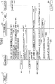
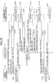
- FIG. 4 is a sequence diagram of one example showing a procedure of the service providing system 1 according to the first embodiment.
- FIG. 5 illustrates one example of a HTTP request that the information storage apparatus 10 receives.
- a user operates the smartphone 11, and selects a file list display process.
- the smartphone 11 sends a file list obtaining request to the information storage apparatus 10 by, for example, a HTTP request (GET) such as that shown in FIG. 5 , in step S1.
- GET HTTP request
- step S2 the WebApi 26 of the information storage apparatus 10 receives the file list obtaining request, and sends a file list obtaining request to the Web control part 29.
- the Web control part 29 responds to the file list obtaining request sent by the WebApi 29, obtains a file list from the document management part 28 and returns the file list to the WebApi 26.
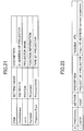
- the WebApi 26 then provides a list of files or folders to the smartphone 11 via a HTTP response such as that shown in FIG. 6 .
- FIG. 6 is a configuration diagram of one example of a response to a file list obtaining request such as that mentioned above.
- the response of FIG. 6 has a JSON format.
- the format of the response is not limited thereto, and any other format can be used as long as it is possible to display a list of files or folders by the smartphone 11.
- An application (software) installed in the smartphone 11 displays, based on such a response to a file list obtaining request shown in FIG. 6 , a file list (including folder(s)) published by the information storage apparatus 10.
- the smartphone 11 sends a thumbnail image obtaining request via, for example, a HTTP request (GET) such as that shown in FIG. 5 , to the information storage apparatus 10 in step S3.
- GET a HTTP request
- step S4 the WebApi 26 of the information storage apparatus 10 receives the thumbnail image obtaining request, and sends a thumbnail image obtaining request to the Web control part 29.
- the Web control part 29 responds to the thumbnail image obtaining request from the WebApi 26, and sends a thumbnail image obtaining request to the document management part 28.
- the document management part 28 obtains a file(s) from the shared folder 27, and generates thumbnail images.
- the Web control part 29 returns the thumbnail images that the document management part 28 has generated to the WebApi 26.
- the WebApi 26 provides the thumbnail images to the smartphone 11 via a HTTP response.
- the application installed in the smartphone 11 displays the thumbnail images based on the response to the thumbnail image obtaining request.
- FIG. 7 is an image diagram of one example of an IT folder selection screen page.
- the user can select, as an IT folder, either "AllUsers" or "yamada".
- FIG. 8 is an image diagram of one example of a folder display screen page.
- the folder display screen page 1010 of FIG. 8 is a screen page example displayed after the "AllUsers" IT folder has been selected from the IT folder selection screen page 1000 of FIG. 7 .
- "category”, "data” and "workflow” are displayed as folders.
- FIG. 9 is an image diagram of one example of a file list display screen page.
- the file list display screen page 1050 of FIG. 9 is a screen page example displayed after the "data" folder has been selected from the folder display selection screen page 1010 of FIG. 8 .
- "Estimate Sheet.doc” and “Scan_20120607.pdf” are displayed as files.
- "Minutes of Meeting” and "memo” are displayed as folders.
- thumbnail images 1051 are displayed for "Estimate Sheet.doc” and “Scan_20120607.pdf” that are the files, and thus, the user can easily determine visually what these files are.
- the file list display screen page 1050 of FIG. 9 displays only files that can be printed by the MFP 13, by displaying only files that are designated such file formats (for example, "rpcs") that the MFP 13 can print for the item "File format(s) to which file can be converted” included in the response shown in FIG. 6 . Further, the file list display screen page 1050 of FIG. 9 can display whether it is necessary to convert the file format(s), by marking a file(s) that is(are) designated such a file format that the MFP 13 can print for the item "File format to which file has been converted” included in the response shown in FIG. 6 .
- step S5 the user operates the smartphone 11 and selects a file to be printed by the MFP 13 from the file list display screen page 1050 of FIG. 9 .
- description will be made assuming that the user has selected the "Estimate Sheet.doc" file from the file list display screen page 1050.
- the smartphone 11 sends a pdf file obtaining request via a HTTP request (GET) shown in FIG. 5 , for example.
- GET HTTP request
- "pdf file” is merely one example, and any other file format can be designated instead as long as the smartphone 11 can display an image of the "Estimate Sheet.doc” file of the file format.
- step S7 the WebApi 26 of the information storage apparatus 10 receives the pdf file obtaining request, and sends a pdf file obtaining request to the Web control part 29.
- the Web control part 29 responds to the pdf file obtaining request and sends a pdf file obtaining request to the document management part 28.
- the document management part 28 obtains the "Estimate Sheet.doc” file from the shared folder 27, and generates a pdf file therefrom. In a case where a pdf file of the "Estimate Sheet.doc” file has been already generated and is placed in the shared folder 27, it is possible to omit the process of generating a pdf file by the document management part 28.
- the Web control part 29 returns the pdf file generated by the document management part 28 to the WebApi 26.
- the WebApi 26 provides the pdf file to the smartphone 11 via a HTTP response.
- FIG. 10 is an image diagram of one example of a file detail display screen page.
- the file detail display screen page 1060 of FIG. 10 is a screen page example displayed after the "Estimate Sheet.doc" file has been selected from the file list display screen page 1050 of FIG. 9 .
- the application of the smartphone 11 can display the image 1063 as a result of obtaining the pdf file. The user then confirms whether the image 1063 displayed on the file detail display screen page 1060 surely corresponds to the file to be printed.
- FIG. 11 is an image diagram of one example of a print setting screen page 1070.
- the user then operates the smartphone 11 and carries out settings for print to be carried out by the MFP 13 via the displayed print setting screen page 1070 of FIG. 11 .
- FIG. 12 is an image diagram of one example of a QR code reading screen page 1150 displayed on the smartphone 11.
- the QR code reading screen page 1150 includes a QR code display area 1151.
- the QR code display area 1151 is an area in which an image taken by the camera function of the smartphone 11 will be displayed.
- steps S9 and S10 of FIG. 4 the user operates the smartphone 11, and adjusts a positional relationship between the QR code displayed on the MFP 13 (step S0) and the smartphone 11 so that the QR code an image of which is thus taken by the camera function of the smartphone 11 will be displayed in the QR code display area 1151 of the QR code reading screen page 1150 displayed on the smartphone 11.
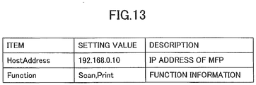
- FIG. 13 is a configuration diagram of one example of the information that the application of the smartphone 11 reads from the QR code displayed in step S0 of FIG. 4 .
- a specific method of obtaining the IP address and function information of the MFP 13 or the like is not limited to the above-mentioned method of obtaining information from a QR code by photographing it. It is also possible to obtain the IP address and function information of the MFP 13 or the like using a communication way for sending and receiving information between the smartphone 11 and the MFP 13 or the like. For example, infrared communication, Bluetooth, NFC or the like can be used for this purpose. Thus, various methods can be used even without using a QR code.
- FIG. 14 is an image diagram of one example of the screen page 1160 indicating that downloading of a print file is being carried out.
- the screen page 1160 of FIG. 14 may be continuously displayed by the smartphone 11 until step S11 described later is completed.
- timing of displaying the QR code on the MFP 13 timing of providing the file list from the information storage apparatus 10 to the smartphone 11 and timing of reading information from the QR code displayed on the MFP 13 by the smartphone 11 are not limited to the order shown in the sequence diagram of FIG. 4 .
- step S11 the application of the smartphone 11 determines a file format as described later depending on the function information that the application of the smartphone 11 has read from the QR code.
- the application of the smartphone 11 determines a file format (for example, "rpcs"), which can be printed by the MFP 13, depending on the function information read from the QR code.
- step S12 the application of the smartphone 11 sends a "rpcs" file obtaining request to the information storage apparatus 10 via a HTTP request (GET) such as that shown in FIG. 5 .
- the rpcs file obtaining request includes information of the file selection and information of the file format determined in step S11.
- Step S13 the WebApi 26 of the information storage apparatus 10 receives the rpcs file obtaining request and sends a corresponding rpcs file obtaining request to the Web control part 29.
- the Web control part 29 responds to the rpcs file obtaining request from the WebApi 26 and sends a corresponding rpcs file obtaining request to the document management part 28.
- the document management part 28 obtains the corresponding file from the shared folder 27 based on the "information of the file selection" included in the rpcs file obtaining request.
- the document management part 28 determines, based on the "information of the file format" included in the rpcs file obtaining request, whether it is necessary to convert the file format of the file thus obtained from the shared folder 27. For example, when the file format of the file obtained from the shared folder 27 is an rpcs format, it is the same as the file format indicated by the "information of the file format", and thus, the document management part 28 determines that conversion of the file format of the file obtained from the shared folder 27 is not necessary.
- the document management part 28 determines that conversion of the file format of the file obtained from the shared folder 27 is necessary. When having determined that it is necessary to convert the file format, the document management part 28 converts the file format into a rpcs format accordingly. Below, a case where the document management part 28 has determined that it is necessary to convert the file format will be described.
- the Web control part 29 then returns the converted file obtained from the document management part 28, the file format of which has been thus converted, to the WebApi 26.
- step S14 the WebApi 26 provides the converted file to the smartphone 11 via a HTTP response.
- step S15 the application of the smartphone 11 transmits the converted file to the MFP 13 as a print file.
- a specific method of thus transmitting a print file to the MFP 13 is, for example, a method of transmitting using a socket communication to the port of the number 9100 ("port 9100") of the MFP 13, as shown in FIG. 15.
- FIG. 15 illustrates one example of a method of transmitting a print file to the MFP 13.
- the MFP 13 carries out print (output) based on the print file, in step S16.
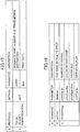
- FIG. 16 is a configuration diagram of one example of print commands included in a print file.
- the print commands of FIG. 16 include the contents of print settings that have been carried out via the print setting screen page 1070 of FIG. 11 (#2 in FIG. 16 ) and a file name of a file to be printed (#1 in FIG. 16 ).
- the MFP 13 can display (in step S0), via a Web browser (not shown), a screen page 1200 including a QR code 1201 as shown in FIG. 17 on an operation panel or the like of the MFP 13 as a result of displaying the QR code display Web Ul 25 of the information storage apparatus 10.
- FIG. 17 is an image diagram of one example of a QR code displayed on the MFP 13. It is noted that the screen page 1200 of FIG. 17 is displayed as a result of a "MFP Everywhere" button 1211 on the top screen page 1210 of the Web browser (not shown) of the MFP 13 shown in FIG. 18 being pressed, for example.
- FIG. 18 is an image diagram of one example of the top screen page displayed on the MFP 13.
- a specific position to affix a seal of the QR code 1201 is preferably a position such that a user can understand that the QR code 1201 is one that is associated with the MFP 13.
- FIG. 19 is a flowchart of one example of a procedure of the smartphone 11. It is noted that the flowchart of FIG. 19 shows the procedure to be carried out after the QR code reading screen page 1150 shown in FIG. 12 has been displayed by the smartphone 11 as mentioned above.
- step S21 of FIG. 19 the application of the smartphone 11 reads the set value of item "Function" shown in FIG. 13 from the QR code that has been taken by the camera function of the smartphone 11.
- step S22 the application of the smartphone 11 determines whether the set value of item "Function" is "Projection” that indicates the projection function (projector 14).
- the application of the smartphone 11 proceeds to step S25, and sends a file obtaining request that designates PDF that can be projected by the projector 14 as a file format to the information storage apparatus 10.
- step S23 determines whether the set value of item "Function” is "Print” that indicates the print function (MFP 13).
- the application of the smartphone 11 proceeds to step S24, and sends a file obtaining request that designates RPCS or PDL that can be printed by the MFP 13 as a file format to the information storage apparatus 10.
- step S23 When the set value of item "Function" is not "Print” that indicates the print function (MFP 13) in step S23, the application of the smartphone 11 proceeds to step S26, and carries out an error display process since it is not possible to determine a file format to be designated in a file obtaining request.
- the smartphone 11 can display, on the smartphone 11, the files placed in the shared folder 27 of the information storage apparatus 10, by installing the WebApi 26 in the information storage apparatus 10.
- a user can obtain from the information storage apparatus 10 a converted file of a file format that can be printed by the MFP 13, by selecting the file via the smartphone 11 and reading via the smartphone 11 information from the QR code 1201 of the MFP 13 that the user wishes to use to print the file.
- the smartphone 11 can cause the MFP 13 to print the converted file thus obtained from the information storage apparatus 10 by transmitting the converted file to the MFP 13 as a print file. It is noted that also the smartphone 11 can store the converted file that has been obtained from the information storage apparatus 10.
- a user can cause the information storage apparatus 10, the smartphone 11 and the MFP 13 to operate in cooperation with each other by holding the smartphone 11 against the MFP 13 at a time of starting print (to cause the smartphone 11 to read information from the QR code of the MFP 13), and thus, the user can easily print by the MFP 13 a file placed in the shared folder 27 of the information storage apparatus 10.
- the sequence diagram of FIG. 4 shows the process of obtaining a file from the information storage apparatus 10 using the smartphone 11, and printing the file by the MFP 13.
- the service providing system 1 according to the first embodiment can also be used, as shown in FIG. 20 , to obtain a file from the information storage apparatus 10 using the smartphone 11, and project the file by the projector 14.
- FIG. 20 is a sequence diagram of another example showing a procedure of the service providing system 1 according to the first embodiment. It is noted that the processes of step S30 and steps S31 to S37 of FIG. 20 are the same as those of step S0 and steps S1 to S7 of FIG. 4 , and thus, duplicate description will be omitted.
- the smartphone 11 When a "projection settings" button (not shown) has been pressed on the file detail display screen page 1060, the smartphone 11 displays a projection setting screen page in step S38. The user then operates the smartphone 11 and carries out settings for projection to be carried out by the projector 14 via the displayed projection setting screen page.
- the user can cause the QR code reading screen page 1150, as shown in FIG. 12 , for example, to be displayed on the smartphone 11.
- steps S39 and S40 the user operates the smartphone 11, and adjusts a positional relationship between the QR code displayed by the projector 14 (step S30) (onto a projection screen 141 or the like as shown in FIG. 23 described later) and the smartphone 11 so that the QR code taken by the camera function of the smartphone 11 will be displayed in the QR code display area 1151 of the QR code reading screen page 1150 displayed on the smartphone 11.
- the application of the smartphone 11 reads, from the QR code taken by the camera function of the smartphone 11, the IP address of the projector 14, a projector name, the function information indicating the projection function that the projector 14 provides, and a type of the projector 14 as shown in FIG. 21.
- FIG. 21 is a configuration diagram of one example of the information that the application of the smartphone 11 reads from the QR code.
- the application of the smartphone 11 After thus reading the IP address and the function information indicating the projection function of the projector 14 from the QR code, the application of the smartphone 11 displays the screen page indicating that downloading is being carried out to the user, as shown in FIG. 14 .
- timing of displaying the QR code by the projector 14 timing of providing the file list from the information storage apparatus 10 to the smartphone 11 and timing of reading information by the smartphone 11 from the QR code displayed by the projector 14 are not limited to the order shown in the sequence diagram of FIG. 20 .
- step S41 the application of the smartphone 11 determines, as shown in FIG. 19 , a file format depending on the function information that the application of the smartphone 11 has read from the QR code. For example, when the function information includes the projection function, the application of the smartphone 11 determines the file format (as PDF, for example) which can be projected by the projector 14.
- step S42 the application of the smartphone 11 sends an image file obtaining request to the information storage apparatus 10 via a HTTP request (GET) such as that shown in FIG. 5 .
- the image file obtaining request includes information of the file selection and information of the file format determined in step S41.
- Step S43 the WebApi 26 of the information storage apparatus 10 receives the image file obtaining request and sends a corresponding image file obtaining request to the Web control part 29.
- the Web control part 29 responds to the image file obtaining request from the WebApi 26 and sends a corresponding image file obtaining request to the document management part 28.
- the document management part 28 obtains the corresponding image file from the shared folder 27 based on the "information of the file selection" included in the image file obtaining request.
- the document management part 28 determines, based on the "information of the file format" included in the image file obtaining request, whether it is necessary to convert the file format of the file thus obtained from the shared folder 27. For example, when the file format of the file obtained from the shared folder 27 is a pdf format, the file format of the file obtained from the shared folder 27 and the file format indicated by the "information of the file format" are the same, and thus, the document management part 28 determines that conversion of the file format of the file obtained from the shared folder 27 is not necessary.
- the document management part 28 determines that conversion of the file format of the file obtained from the shared folder 27 is necessary.
- the document management part 28 converts the file format of the file obtained from the shared folder 27 into a pdf format.
- the Web control part 29 then returns the converted file obtained from the document management part 28, the file format of which has been thus converted, to the WebApi 26.
- step S44 the WebApi 26 provides the converted file to the smartphone 11 via a HTTP response.
- step S45 the application of the smartphone 11 transmits the converted file to the projector 14 as a projection file. It is noted that also the smartphone 11 can store the converted file that has been obtained from the information storage apparatus 10.
- a specific method of transmitting a projection file to the projector 14 is, for example, a method of transmitting it using a WebApi that is published by the projector 14, as shown in FIG. 22.
- FIG. 22 illustrates one example of a method of transmitting a projection file to the projector 14.
- the projector 14 When having received the projection file, the projector 14 carries out projection (output) based on the projection file, in step S46.
- the projector 14 can project a screen page including the QR code 1300 as shown in FIG. 23 on the projection screen 141 or the like, or it is also possible to affix a seal of the QR code 1301 onto the housing of the projector 14, for example.
- FIG. 23 is an image diagram of one example of a QR code to be displayed by or on the projector 14.
- the projector 14 can thus project the QR code 1300 by displaying via a Web browser (not shown) the QR code display Web Ul 25 of the information storage apparatus 10.
- the projector 14 stores image data of the QR code 1300 in the projector 14 itself, or obtains image data of the QR code 1300 from the outside.
- a specific position to affix a seal of the QR code 1301 is preferably a position such that a user can understand that the QR code 1301 is one that is associated with the projector 14.
- the processes have been shown for a case of obtaining a file from the information storage apparatus 10 using the smartphone 11 and printing the file by the MFP 13.
- the service providing system 1 according to the first embodiment can also be used for a case of, as shown in a sequence diagram of FIG. 24 , using the tablet terminal 12 to obtain a file from the information storage apparatus 10 and print the file by the MFP 13.
- FIG. 24 is a sequence diagram of yet another example of a procedure of the service providing system 1 according to the first embodiment. Since processes of step S50 and steps from S51 to S66 in the sequence diagram of FIG. 24 are the same as those of step S0 and steps from S1 to S16 of FIG. 4 except that the role of the smartphone 11 in the procedure of FIG. 4 is replaced by the tablet terminal 12 in the procedure of FIG. 24 , description will be omitted.
- the processes have been shown for a case of obtaining a file from the information storage apparatus 10 using the smartphone 11 and projecting the file by the projector 14.
- the service providing system 1 according to the first embodiment can also be used for a case of, in the same manner as the case of FIG. 24 , using the tablet terminal 12 to obtain a file from the information storage apparatus 10 and project the file by the projector 14 instead of printing the file by the MFP 13.
- the service providing system of the first embodiment it is possible to obtain, via an information processing apparatus such as the smartphone 11 or the tablet terminal 12, a file list and a file of a file format depending on the electronic apparatus that will output electronic data, as a result of installing the WebApi 26 in the information storage apparatus 10.
- an information processing apparatus such as the smartphone 11 or the tablet terminal 12
- a file list and a file of a file format depending on the electronic apparatus that will output electronic data as a result of installing the WebApi 26 in the information storage apparatus 10.
- a service providing system 1 according to the second embodiment has the same system configuration, hardware configuration and software configuration as those of the service providing system 1 according to the first embodiment described above. Thus, the description of the system configuration, hardware configuration and software configuration will be omitted.
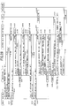
- FIG. 25 is a sequence diagram showing one example of a procedure of the service providing system 1 according to the second embodiment.
- FIG. 26 illustrates one example of a HTTP request that the information storage apparatus 10 receives.
- a user operates the tablet terminal 12, and selects a file list display process.
- the tablet terminal 12 sends a file list obtaining request to the information storage apparatus 10 by, for example, a HTTP request (GET) such as that shown in FIG. 5 , in step S101.
- GET HTTP request
- step S102 the WebApi 26 of the information storage apparatus 10 receives the file list obtaining request, and sends a file list obtaining request to the Web control part 29.
- the Web control part 29 responds to the file list obtaining request sent by the WebApi 29, obtains a file list from the document management part 28 and returns the file list to the WebApi 26.
- the WebApi 26 provides the file list to the tablet terminal 12 via a HTTP response such as that shown in FIG. 6 .
- An application installed in the tablet terminal 12 displays a file list published by the information storage apparatus 10 based on the response to the file list obtaining request, on the folder display screen page 1010 of FIG. 8 described above, for example.
- a user can request to create a folder by pressing a "Create Folder” button 1012 on the folder display screen page 1010 of FIG. 8 .
- a description will be now made assuming that the user has requested to create a "folder A”.
- the tablet terminal 12 sends a folder creation request to the information storage apparatus 10 via, for example, a HTTP request (POST) shown in FIG. 26 , in step S103.
- POST HTTP request
- step S104 the WebApi 26 of the information storage apparatus 10 receives the folder creation request, and sends a folder creation request to the Web control part 29.
- the Web control part 29 responds to the folder creation request sent by the WebApi 29 and creates the "folder A" in the shared folder 27.
- FIG. 27 is an image diagram of one example of a folder selection screen page 1030. The user can select a folder, to which uploading will be carried out, from the folder selection screen page 1030.
- step S105 the user operates the tablet terminal 12 and selects a folder, to which a file (i.e., a file obtained from photographing by a built-in camera, a file included in a memory card or the like) included in the tablet terminal 12 is to be stored, from among folders displayed on the folder selection screen page 1030 of FIG. 27 .
- a file i.e., a file obtained from photographing by a built-in camera, a file included in a memory card or the like
- step S106 When the user has requested to upload the "file a" to the "folder A", the tablet terminal 12 proceeds to step S106, and sends a file upload request to the information storage apparatus 10 via, for example, a HTTP request (POST) shown in FIG. 26 .
- step S107 the WebApi 26 of the information storage apparatus 10 receives the file upload request, and sends a file upload request to the Web control part 29.
- the Web control part 29 responds to the file upload request sent by the WebApi 29 and stores the "file a" in the "folder A".
- the smartphone 11 sends a file list obtaining request to the information storage apparatus 10 by, for example, a HTTP request (GET) such as that shown in FIG. 5 , in step S108.
- GET HTTP request
- step S109 the information storage apparatus 10 provides a file list to the smartphone 11, in the same manner as step S102.
- the "folder A” created via the tablet terminal 12 in step S104 is included. The user therefore can check, via the smartphone 11, the "file a" that has been uploaded to the "folder A”.
- step S110 the user operates the smartphone 11 and selects the "folder A” from among the folders displayed on the folder selection screen page 1030 of FIG. 27 .
- the smartphone 11 can select the "folder A” that has been created via the tablet terminal 12.
- step S111 the smartphone 11 proceeds to step S111, and sends a file upload request to the information storage apparatus 10 via, for example, a HTTP request (POST) shown in FIG. 26 .
- POST HTTP request
- step S112 the WebApi 26 of the information storage apparatus 10 receives the file upload request, and sends a file upload request to the Web control part 29.
- the Web control part 29 responds to the file upload request sent by the WebApi 29, and stores the "file b" in the "folder A".
- the smartphone 11 sends a file list obtaining request to the information storage apparatus 10 by, for example, a HTTP request (GET) such as that shown in FIG. 5 , in step S113.
- GET HTTP request
- step S114 the information storage apparatus 10 provides a file list to the smartphone 11, in the same manner as step S102.
- the smartphone 11 When creation of a "folder B" has been thus requested by the user, the smartphone 11 sends a folder creation request to the information storage apparatus 10 via, for example, a HTTP request (POST) shown in FIG. 26 , in step S115.
- a HTTP request POST
- step S116 the WebApi 26 of the information storage apparatus 10 receives the folder creation request, and sends a folder creation request to the Web control part 29.
- the Web control part 29 responds to the folder creation request sent by the WebApi 29 and creates the "folder B" in the shared folder 27.
- the user operates the tablet terminal 12 different from the smartphone 11, and selects a file list display process.
- the tablet terminal 12 sends a file list obtaining request to the information storage apparatus 10 by, for example, a HTTP request (GET) such as that shown in FIG. 5 , in step S117.
- GET HTTP request
- step S118 the information storage apparatus 10 provides a file list to the tablet terminal 12, in the same manner as step S102.
- step S119 the user operates the tablet terminal 12 and selects the "folder B" from the folder selection screen page 1030.
- the tablet terminal 12 can select the "folder B" that has been created via the smartphone 11.
- step S120 the tablet terminal 12 receives the file upload request, and sends a file upload request to the Web control part 29.
- the Web control part 29 responds to the file upload request sent by the WebApi 29 and stores the "file c" in the "folder B".
- a user by installing the WebApi 26 that is compatible with POST of a HTTP request in the information storage apparatus 10, a user can create a folder using an information processing apparatus (the tablet terminal 12), and then, the user can use another information processing apparatus (the smartphone 11) to view the same folder and upload a file to the folder.
- an information processing apparatus the tablet terminal 12
- another information processing apparatus the smartphone 11
- a user can use an information processing apparatus to view a file which the user has uploaded to a folder using another information processing apparatus.
- an information processing apparatus to view a file which the user has uploaded to a folder using another information processing apparatus.
- POST HTTP request
- the service providing system 1 according to the second embodiment can also be used to, as shown in FIG. 28 , cause a folder that has been created or a file that has been uploaded using an information processing apparatus (tablet terminal 12) to be printed by the MFP 12 using another information processing apparatus (smartphone 11).
- FIG. 28 is a sequence diagram of anther example of a procedure of the service providing system according to the second embodiment. It is noted that processes of steps S131 to S151 of FIG. 28 are the same as those of steps S101 to S121, and thus, duplicate description will be omitted.
- the user operates the smartphone 11, and selects a file list display process.
- the smartphone 11 sends a file list obtaining request to the information storage apparatus 10 by, for example, a HTTP request (GET) such as that shown in FIG. 5 , in step S152.
- GET a HTTP request
- the WebApi 26 of the information storage apparatus 10 provides a list of files to the smartphone 11, in the same manner as step S2 of FIG. 4 .
- step S154 the smartphone 11 sends a thumbnail image obtaining request via, for example, a HTTP request (GET) such as that shown in FIG. 5 , to the information storage apparatus 10.
- step S155 the WebApi 26 of the information storage apparatus 10 provides thumbnail images to the smartphone 11 in the same way as step S4 of FIG. 4 .
- the application installed in the smartphone 11 displays a file list published by the information storage apparatus 10 based on the response to the thumbnail image obtaining request shown in FIG. 6 .
- the file list thus displayed by the smartphone 11 folders that have been created and files that have been uploaded via the tablet terminal 12 are included.
- step S156 also, the user can view, using the smartphone 11, the folders that have been created and the files that have been uploaded using the tablet terminal 12, and the user can select, using the smartphone 11, a file to be printed by the MFP 13 from among the files that have been uploaded using the tablet terminal 12.
- steps S130 and steps starting from step S157 are the same as those of step S0 and steps starting from step S6 of FIG. 4 , and thus, the duplicate description will be omitted.
- the user can cause, using another information processing apparatus (smartphone 11), the projector 14 to project a folder that the user has created or a file that the user has uploaded using an information processing apparatus (tablet terminal 12).
- another information processing apparatus smart phone 11
- the projector 14 to project a folder that the user has created or a file that the user has uploaded using an information processing apparatus (tablet terminal 12).
- a user can create a folder using an information processing apparatus, then select the folder and upload a file to the selected folder using another information processing apparatus, by installing the WebApi 26 in the information storage apparatus 10. Also, a user can view, using another information processing apparatus, a file that the user has uploaded to a folder using an information processing apparatus.
- facsimile transmission conditions are set instead of setting print conditions (print settings).
- the facsimile transmission conditions include, for example, whether to attach a letter of transmittal, a transmission result notification destination, whether to print date and time, transmission source information, transmission destination information and/or the like. Further, it is also possible to use, for the facsimile transmission conditions, information of another application that is installed and operates in the smartphone. For example, it is possible for a user to select a transmission destination telephone number from among data that is managed by the other application installed for managing addresses.
- the information storage apparatus 10 generates facsimile transmission image data according to the received facsimile transmission conditions (facsimile transmission settings). It is noted that the information storage apparatus 10 can use the facsimile transmission image data that is previously generated, or can generate the facsimile transmission image data after receiving a facsimile transmission instruction from the smartphone 11.
- the thus generated facsimile transmission image data is then transmitted to the MFP 13 through the information storage apparatus 10.
- the MFP 13 transmits the received facsimile transmission image data to the transmission destination.
- a user can obtain advantageous effects as follows. That is, by holding an information processing apparatus (operation terminal) such as the smartphone 11 or the tablet terminal 12 against an electronic apparatus such as the MFP 13 or the projector 14 to obtain information for identifying the electronic apparatus such as a QR code, the user can cause a cooperative processing apparatus such as the information storage apparatus 10, the information processing apparatus and the electronic apparatus to operate in cooperation with each other, and receive various services that are realized by using the electronic apparatus.
- an information processing apparatus operation terminal
- the smartphone 11 or the tablet terminal 12 against an electronic apparatus such as the MFP 13 or the projector 14 to obtain information for identifying the electronic apparatus such as a QR code
- a cooperative processing apparatus such as the information storage apparatus 10
- the information processing apparatus and the electronic apparatus to operate in cooperation with each other, and receive various services that are realized by using the electronic apparatus.
- the service providing systems 1 can provide various services, as a result of an electronic apparatus such as the MFP 13 or the projector 14, an information processing apparatus (operation terminal) such as the smartphone 11 or the tablet terminal 12 and a cooperative processing apparatus such as the information storage apparatus 10 operating in cooperation with each other by a cooperation method that is depending on the respective services such as print, projection and scan to be provided.
- an electronic apparatus such as the MFP 13 or the projector 14
- an information processing apparatus operation terminal
- a cooperative processing apparatus such as the information storage apparatus 10 operating in cooperation with each other by a cooperation method that is depending on the respective services such as print, projection and scan to be provided.
- a cooperation method concerning a new service to be provided by an electronic apparatus such as the MFP 13, the projector 14 or another new electronic apparatus can be previously defined in the service providing systems according to the embodiments.
- an electronic apparatus such as the MFP 13, the projector 14 or another new apparatus, an information processing apparatus (operation terminal) such as the smartphone 11 or the tablet terminal 12 and a cooperative processing apparatus such as the information storage apparatus 10 to operate in cooperation with each other by the cooperation method that is depending on the new service.
- an electronic apparatus such as the MFP 13, the projector 14 or another new apparatus, an information processing apparatus (operation terminal) such as the smartphone 11 or the tablet terminal 12 and a cooperative processing apparatus such as the information storage apparatus 10
- an information processing apparatus operation terminal
- a cooperative processing apparatus such as the information storage apparatus 10
- the service providing systems according to the embodiments it is possible to previously define such that the process shown in the sequence diagram of FIG. 4 is to be carried out, in a case where the MFP 13 has a function of directly communicating with the smartphone 11. Further, in the service providing systems according to the embodiments, it is possible to previously define such that the information storage apparatus 10 is caused to carry out communication with the MFP 13, in a case where the MFP 13 does not have a function of directly communicating with the smartphone 11. Thus, in the service providing systems according to the embodiments, it is possible to change a process(es) depending on whether the MFP 13 has a function of directly communicating with the smartphone 11. Thus, it is possible to provide a service(s) depending on various MFPs 13.
- the methods of controlling operations of the same, and the output systems of the embodiments, apparatuses included in the system operate in cooperation with each other to provide a service(s).
Landscapes
- Engineering & Computer Science (AREA)
- Theoretical Computer Science (AREA)
- Human Computer Interaction (AREA)
- Physics & Mathematics (AREA)
- General Physics & Mathematics (AREA)
- General Engineering & Computer Science (AREA)
- Multimedia (AREA)
- Signal Processing (AREA)
- General Health & Medical Sciences (AREA)
- Health & Medical Sciences (AREA)
- Biomedical Technology (AREA)
- Computer Networks & Wireless Communication (AREA)
- Facsimiles In General (AREA)
- Information Transfer Between Computers (AREA)
- Accessory Devices And Overall Control Thereof (AREA)
Abstract
Description
- The present invention relates to an operation terminal, a method of controlling operations of the same, and an output system.
- For example, a host session management server is known, which can easily realize a communication service using a plurality of different apparatuses that operate in cooperation with each other (for example, see Japanese Laid-Open Patent Application No.
2011-35833 - Recently, users use various electronic apparatuses such as a printer, a MultiFunction Peripheral (MFP), a projector and so forth, which output electronic data, and/or various information processing apparatuses such as a portable phone, a smartphone, a tablet terminal and so forth. Concerning such a mode (system) using these electronic apparatuses and information processing apparatuses, it is expected to improve the utility values thereof as a result of causing the various electronic apparatuses and information processing apparatuses to operate in cooperation with each other.
- For this purpose, in such a system of using electronic apparatuses and information processing apparatuses, a mechanism has been demanded by which various electronic apparatuses and information processing apparatuses operate in cooperation with each other to provide a service(s).
- According to one embodiment of the present invention, an operation terminal includes a determination part that determines, based on information that the operation terminal obtains from the outside in response to an operation performed on the operation terminal, an electronic apparatus from among a plurality of electronic apparatuses connected to the operation terminal, the electronic apparatus being one which is to output electronic data stored in an information storage apparatus connected to the operation terminal; an obtaining part that obtains, from the information storage apparatus, electronic data from among a plurality of sets of electronic data stored in the information storage apparatus in a format that the determined electronic apparatus is capable of outputting; and a transmission part that transmits the obtained electronic data to the determined electronic apparatus.
- Other objects, features and advantages of the present invention will become more apparent from the following detailed description when read in conjunction with the accompanying drawings.
- This application is a divisional of 13175721.3 and also disclosed herein are the following concepts:
-
Concept 1. An operation terminal comprising, a determination part that determines, based on information that the operation terminal obtains from the outside in response to an operation performed on the operation terminal, an electronic apparatus from among a plurality of electronic apparatuses connected to the operation terminal, the electronic apparatus being one which is to output electronic data stored in an information storage apparatus connected to the operation terminal; an obtaining part that obtains, from the information storage apparatus, electronic data from among a plurality of sets of electronic data stored in the information storage apparatus in a format that the determined electronic apparatus is capable of outputting; and a transmission part that transmits the obtained electronic data to the determined electronic apparatus. -
Concept 2. The operation terminal as described inconcept 1, wherein the information that the operation terminal obtains from the outside includes at least identification information for identifying the electronic apparatus and function information concerning a function of the electronic apparatus, the determination part determines the electronic apparatus based on the identification information included in the obtained information, and the obtaining part obtains the electronic data in the format being determined based on the function information included in the obtained information. -
Concept 3. The operation terminal as described inconcept -
Concept 4. The operation terminal as described in any one ofconcepts -
Concept 5. A method of controlling operations of an operation terminal, the method comprising, determining, based on information that the operation terminal obtains from the outside in response to an operation performed on the operation terminal, an electronic apparatus from among a plurality of electronic apparatuses connected to the operation terminal, the electronic apparatus being one which is to output electronic data stored in an information storage apparatus connected to the operation terminal; obtaining, from the information storage apparatus, electronic data from among a plurality of sets of electronic data stored in the information storage apparatus in a format that the determined electronic apparatus is capable of outputting; and transmitting the obtained electronic data to the determined electronic apparatus. -
Concept 6. The method as described inconcept 5, wherein the information that the operation terminal obtains from the outside includes at least identification information for identifying the electronic apparatus and function information concerning a function of the electronic apparatus,
in the determining, the operation terminal determines the electronic apparatus based on the identification information included in the obtained information, and
in the obtaining, the operation terminal obtains the electronic data in the format being determined based on the function information included in the obtained information. -
Concept 7. The method as described inconcept
in the transmitting, the operation terminal transmits the obtained electronic data to the electronic apparatus, and also transmits output settings for causing the electronic apparatus to output the electronic data. -
Concept 8. The method as described in any one ofconcepts -
Concept 9. An output system comprising, the operation terminal concepted inconcept 1; and an information storage apparatus connected with the operation terminal and including a data transmission part that transmits, to the operation terminal, the electronic data in the format requested by an obtaining request, in response to the obtaining request that the operation terminal has transmitted for requesting the electronic data from among the plurality of sets of electronic data stored in the information storage apparatus in the format that the electronic apparatus determined by the determination part of the operation terminal is capable of outputting. -
Concept 10. The output system as described inconcept 9, wherein the information storage apparatus further includes a conversion part that converts a format of the electronic data stored in the information storage apparatus, the conversion part converts the electronic data requested by the obtaining request into electronic data of the data format requested by the obtaining request, and the data transmission part transmits the electronic data converted by the conversion part to the operation terminal. -
-
FIG. 1 is a configuration diagram of one example of a service providing system according to a first embodiment; -
FIG. 2 is a hardware configuration diagram of one example of a computer system according to the first embodiment; -
FIG. 3 is a processing block diagram of one example of an information storage apparatus according to the first embodiment; -
FIG. 4 is a sequence diagram of one example of a procedure of the service providing system according to the first embodiment; -
FIG. 5 illustrates one example of a HTTP request that the information storage apparatus receives; -
FIG. 6 is a configuration diagram of one example of a response to a file list obtaining request; -
FIG. 7 is an image diagram of one example of an IT folder selection screen page; -
FIG. 8 is an image diagram of one example of a folder display screen page; -
FIG. 9 is an image diagram of one example of a file list display screen page; -
FIG. 10 is an image diagram of one example of a file detail display screen page; -
FIG. 11 is an image diagram of one example of a print setting screen page; -
FIG. 12 is an image diagram of one example of a QR code reading screen page; -
FIG. 13 is a configuration diagram of one example of information to be read from a QR code; -
FIG. 14 is an image diagram of one example of a screen page indicating that downloading is being carried out: -
FIG. 15 illustrates one example of a method of transmitting a print file to a MFP; -
FIG. 16 is a configuration diagram of one example of print commands included in the print file; -
FIG. 17 is an image diagram of one example of the QR code displayed on the MFP; -
FIG. 18 is an image diagram of one example of a top screen page displayed on the MFP; -
FIG. 19 is a flowchart of one example showing a procedure of a smartphone; -
FIG. 20 is a sequence diagram of another example showing a procedure of the service providing system according to the first embodiment; -
FIG. 21 is a configuration diagram of another example of information to be read from a QR code; -
FIG. 22 illustrates one example of a method of transmitting a projection file to a projector; -
FIG. 23 is an image diagram of one example of the QR code displayed by the projector; -
FIG. 24 is a sequence diagram of yet another example showing a procedure of the service providing system according to the first embodiment; -
FIG. 25 is a sequence diagram of one example showing a procedure of a service providing system according to a second embodiment; -
FIG. 26 illustrates one example of a HTTP request that the information storage apparatus receives; -
FIG. 27 is an image diagram of a folder selection screen page; and -
FIG. 28 is a sequence diagram of yet another example showing a procedure of the service providing system according to the second embodiment. - Below, the embodiments of the present invention will be described.
-
FIG. 1 is a configuration diagram of one example of the service providing system according to the first embodiment. In theservice providing system 1 ofFIG. 1 , for example, aninformation storage apparatus 10, one ormore smartphones 11, one ormore tablet terminals 12, one ormore MFPs 13 and one ormore projectors 14 are connected to a network N1 such as a Local Area Network (LAN). - As the network N1, it is possible to use a network of a private environment such as an intranet, for example. The
smartphones 11 and thetablet terminals 12 are examples of information processing apparatuses (operation terminals) that users carry and operate. Specific examples of the information processing apparatuses (operation terminals) may be apparatuses that users can operate, and thus include, not only the above-mentionedsmartphones 11 and thetablet terminals 12, but also portable phones, notebook-size Personal Computers (PC), and so forth. - The MFPs 13 and the
projectors 14 are examples of electronic apparatuses that provide services such as print, scan, projection and so forth. Specific examples of the electronic apparatuses may be apparatuses that can provide services, and thus include, not only the above-mentionedMFPs 13 and theprojectors 14, but also printers, scanners, copiers, image display apparatuses, and so forth. - The MFPs 13 are examples of image forming apparatuses. The MFPs 13 have image taking functions, image forming functions and communication functions, and can be used as printers, facsimile machines, scanners and copiers. The
projectors 14 are examples of image projection apparatuses, and have projection functions and communication functions. - The
information storage apparatus 10 is one example of an information processing apparatus and is one example of a cooperative processing apparatus. Theinformation storage apparatus 10 carries out such sophisticated processes that the MFPs 13 andprojectors 14 cannot carry out, and carries out processes as a file server. Theinformation storage apparatus 10 provides services using electronic apparatuses such as the MFPs 13 and/or theprojectors 14 in cooperation with information processing apparatuses (operation terminals) such as thesmartphones 11 and/or thetablet terminals 12. It is noted that theinformation storage apparatus 10 may be configured by a plurality of computers in a decentralized manner. - The
information storage apparatus 10 is realized, for example, by a computer system having the hardware configuration shown inFIG. 2 . Also, the other information processing apparatuses such as thesmartphones 11 and thetablet terminals 12 include the hardware configurations shown inFIG. 2. FIG. 2 is a hardware configuration diagram of one example of the computer systems according to the first embodiment. - The
computer system 100 ofFIG. 2 includes aninput device 101, adisplay device 102, an external I/F 103, aRAM 104, aROM 105, aCPU 106, a communication I/F 107 and a Hard Disk Drive (HDD) 108, which are connected together via a bus B. Theinput device 101 includes a keyboard, a mouse and so forth, and is used to input respective operation signals. - The
display device 102 includes a display and/or the like, and displays processing results of thecomputer system 100. The communication I/F 107 is an interface for connecting thecomputer system 100 to the network N1. Thereby, thecomputer system 100 can carry out data communication with the other apparatuses via the communication I/F 107. - The
HDD 108 is a nonvolatile storage device storing programs and data. The programs stored by theHDD 108 include an Operating System (OS) that is basic software controlling the entirety of thecomputer system 100, application software providing various functions under the control of the OS, and so forth. TheHDD 108 manages the stored programs and data using a predetermined file system and/or DataBase (DB). - The external I/
F 103 is an interface between thecomputer system 100 and external devices. The external devices include arecording medium 103a and so forth. Thereby, thecomputer system 100 can carry out reading information from and/or writing information to therecording medium 103a via the external I/F 103. It is noted that specific examples of therecording medium 103a include a flexible disk, a CD, a Digital Versatile Disk (DVD), a SD memory card, a Universal Serial Bus memory (USB memory) and so forth. - The
ROM 105 is a nonvolatile semiconductor memory (storage device) and thus can store programs and/or data even after the power supply has been turned off. TheROM 105 stores programs and data such as a Basic Input/Output System (BIOS) to be executed when thecomputer system 100 is started up, OS settings, network settings, and so forth. TheRAM 104 is a volatile semiconductor memory (storage device) and temporarily stores programs and/or data. - The
CPU 106 includes an arithmetic and logic unit(s), reads programs and/or data from storage device(s) such as theROM 105 and/orHDD 108 to theRAM 140, carries out processes, and thus, realizes controls and/or functions of the entirety of thecomputer system 100. - The
computer system 100 according to the first embodiment can realize various processes described later using this hardware configuration. - The
information storage apparatus 10 according to the first embodiment includes the processing blocks shown inFIG. 3 , for example. Theinformation storage apparatus 10 executes a program(s), and thus, realizes respective functions of anOS 21, aWeb server 22, anapplication server 23, aWeb Ul 24, a QR codedisplay Web Ul 25, aWebApi 26, a sharedfolder 27, adocument management part 28 and aWeb control part 29. - The
OS 21 is the OS of theinformation storage apparatus 10, and controls the entirety of the system of theinformation storage apparatus 10. TheOS 21 is, for example, Windows (registered trademark), Linux (registered trademark) or the like. - The
Web server 22 is software for transmitting and receiving information using Hyper Text Transfer Protocol (HTTP). TheWeb server 22 is, for example, Apache (registered trademark), IIS (registered trademark) or the like. - The
application server 23 is software operating as plug-in of theWeb server 22, for example. Theapplication server 23 is, for example, Tomcat (registered trademark) or the like. - The
Web Ul 24 displays a system setting screen page in response to a HTTP request. A user can change settings via the system setting screen page using a Web browser (not shown). - The OR code display Web Ul 125 displays, on the electronic apparatus such as the
MFP 13, a screen page of OR code (registered trademark) as one example of code information, in response to a HTTP request. The OR code is a two-dimensional code of a matrix type. - The Web Application programming interface (WebApi) 26 can be used via the network N1. The WebApi receives an HTTP request, carries out a process(s) according to the HTTP request, and sends an HTTP response.
- The
WebApi 26 is an interface that is previously defined and provided for receiving a request from the information processing apparatus such as thesmartphone 11, thetablet terminal 12 or the like, and includes a function(s), a class(es) and/or the like. - Further, it is possible to provide the
WebApi 26 in a form of a Software Development Kit (SDK), to a developer who develops applications to be installed in the information processing apparatus(es). The developer can develop application(s) using the SDK. The SDK may also be provided to a third vender other than a person who provides theinformation storage apparatus 10. The third vendor can develop an application(s) using the provided SDK. The application(s) developed using the SDK can be installed in the information processing apparatus(s). - By thus providing the WebApi of the
information storage apparatus 10 as a SDK, it is possible to install, in the information processing apparatus(es), not only an application(s) developed by a person who provides theinformation storage apparatus 10 but also an application(s) developed by a third vendor. - The shared
folder 27 is a folder published to the network N1 by a Server Message Block (SMB) protocol. A user can access the sharedfolder 27 using the information processing apparatus such as thesmartphone 11 or thetablet terminal 12. It is noted that the sharedfolder 27 is one example of a storage part - The
document management part 28 manages a file(s) placed in the sharedfolder 27 and carries out data conversion in response to a request given by theWeb control part 29. It is noted that a "file(s)" in the first embodiment is(are) one form of data. TheWeb control part 29 carries out a process of controlling thedocument management part 28 according to a request given by theWebApi 26. - It is noted that, generally, two processes operate in the
information storage apparatus 10. One of these two processes includes theWeb server 22, theapplication server 23, theWeb Ul 24, the QR codedisplay Web Ul 25 and theWebApi 26. The other process includes the sharedfolder 27, thedocument management part 28 and theWeb control part 29. Therefore, theWebApi 26 and theWeb control part 29 carry out interprocess communication. - Below, details of processing of the
service providing system 1 according to the first embodiment will be described. - Here, processing will be described for a case where, using the
smartphone 11, a file that theinformation storage apparatus 10 has is printed by theMFP 13.FIG. 4 is a sequence diagram of one example showing a procedure of theservice providing system 1 according to the first embodiment.FIG. 5 illustrates one example of a HTTP request that theinformation storage apparatus 10 receives. - First, a user operates the
smartphone 11, and selects a file list display process. When the file list display process has been thus selected by the user, thesmartphone 11 sends a file list obtaining request to theinformation storage apparatus 10 by, for example, a HTTP request (GET) such as that shown inFIG. 5 , in step S1. - Then, in step S2, the
WebApi 26 of theinformation storage apparatus 10 receives the file list obtaining request, and sends a file list obtaining request to theWeb control part 29. TheWeb control part 29 responds to the file list obtaining request sent by theWebApi 29, obtains a file list from thedocument management part 28 and returns the file list to theWebApi 26. TheWebApi 26 then provides a list of files or folders to thesmartphone 11 via a HTTP response such as that shown inFIG. 6 . -
FIG. 6 is a configuration diagram of one example of a response to a file list obtaining request such as that mentioned above. The response ofFIG. 6 has a JSON format. However, the format of the response is not limited thereto, and any other format can be used as long as it is possible to display a list of files or folders by thesmartphone 11. An application (software) installed in thesmartphone 11 displays, based on such a response to a file list obtaining request shown inFIG. 6 , a file list (including folder(s)) published by theinformation storage apparatus 10. - In a case where thumbnail images (miniaturized images) are needed to display the file list, the
smartphone 11 sends a thumbnail image obtaining request via, for example, a HTTP request (GET) such as that shown inFIG. 5 , to theinformation storage apparatus 10 in step S3. - In step S4, the
WebApi 26 of theinformation storage apparatus 10 receives the thumbnail image obtaining request, and sends a thumbnail image obtaining request to theWeb control part 29. TheWeb control part 29 responds to the thumbnail image obtaining request from theWebApi 26, and sends a thumbnail image obtaining request to thedocument management part 28. - The
document management part 28 obtains a file(s) from the sharedfolder 27, and generates thumbnail images. TheWeb control part 29 returns the thumbnail images that thedocument management part 28 has generated to theWebApi 26. TheWebApi 26 provides the thumbnail images to thesmartphone 11 via a HTTP response. The application installed in thesmartphone 11 displays the thumbnail images based on the response to the thumbnail image obtaining request. - By repeating the processes of steps S1 to S4, the
smartphone 11 displays screen pages such as those shown inFIGs. 7 ,8 and9 .FIG. 7 is an image diagram of one example of an IT folder selection screen page. Via the IT folderselection screen page 1000 ofFIG. 7 , the user can select, as an IT folder, either "AllUsers" or "yamada". -
FIG. 8 is an image diagram of one example of a folder display screen page. The folderdisplay screen page 1010 ofFIG. 8 is a screen page example displayed after the "AllUsers" IT folder has been selected from the IT folderselection screen page 1000 ofFIG. 7 . On the folderdisplay screen page 1010 ofFIG. 8 , "category", "data" and "workflow" are displayed as folders. -
FIG. 9 is an image diagram of one example of a file list display screen page. The file listdisplay screen page 1050 ofFIG. 9 is a screen page example displayed after the "data" folder has been selected from the folder displayselection screen page 1010 ofFIG. 8 . On the file listdisplay screen page 1050 ofFIG. 9 , "Estimate Sheet.doc" and "Scan_20120607.pdf" are displayed as files. Further, on the file listdisplay screen page 1050 ofFIG. 9 , "Minutes of Meeting" and "memo" are displayed as folders. - On the file list display screen page of
FIG. 9 , thethumbnail images 1051 are displayed for "Estimate Sheet.doc" and "Scan_20120607.pdf" that are the files, and thus, the user can easily determine visually what these files are. - Further, it is possible that the file list
display screen page 1050 ofFIG. 9 displays only files that can be printed by theMFP 13, by displaying only files that are designated such file formats (for example, "rpcs") that theMFP 13 can print for the item "File format(s) to which file can be converted" included in the response shown inFIG. 6 . Further, the file listdisplay screen page 1050 ofFIG. 9 can display whether it is necessary to convert the file format(s), by marking a file(s) that is(are) designated such a file format that theMFP 13 can print for the item "File format to which file has been converted" included in the response shown inFIG. 6 . - In step S5, the user operates the
smartphone 11 and selects a file to be printed by theMFP 13 from the file listdisplay screen page 1050 ofFIG. 9 . Here, description will be made assuming that the user has selected the "Estimate Sheet.doc" file from the file listdisplay screen page 1050. - When the "Estimate Sheet.doc" file, for example, has been thus selected from the file list
display screen page 1050, thesmartphone 11 sends a pdf file obtaining request via a HTTP request (GET) shown inFIG. 5 , for example. It is noted that "pdf file" is merely one example, and any other file format can be designated instead as long as thesmartphone 11 can display an image of the "Estimate Sheet.doc" file of the file format. - In step S7, the
WebApi 26 of theinformation storage apparatus 10 receives the pdf file obtaining request, and sends a pdf file obtaining request to theWeb control part 29. TheWeb control part 29 responds to the pdf file obtaining request and sends a pdf file obtaining request to thedocument management part 28. - The
document management part 28 obtains the "Estimate Sheet.doc" file from the sharedfolder 27, and generates a pdf file therefrom. In a case where a pdf file of the "Estimate Sheet.doc" file has been already generated and is placed in the sharedfolder 27, it is possible to omit the process of generating a pdf file by thedocument management part 28. TheWeb control part 29 returns the pdf file generated by thedocument management part 28 to theWebApi 26. TheWebApi 26 provides the pdf file to thesmartphone 11 via a HTTP response. - The application installed in the
smartphone 11 displays a file detaildisplay screen page 1060 such as that shown inFIG. 10 based on the response to the pdf file obtaining request.FIG. 10 is an image diagram of one example of a file detail display screen page. The file detaildisplay screen page 1060 ofFIG. 10 is a screen page example displayed after the "Estimate Sheet.doc" file has been selected from the file listdisplay screen page 1050 ofFIG. 9 . - On the file detail
display screen page 1060 ofFIG. 10 , an image (detailed image) 1063 of the "Estimate Sheet.doc" selected from the file listdisplay screen page 1050 ofFIG. 9 is displayed. - The application of the
smartphone 11 can display theimage 1063 as a result of obtaining the pdf file. The user then confirms whether theimage 1063 displayed on the file detaildisplay screen page 1060 surely corresponds to the file to be printed. - After that, the user carries out print settings if necessary. Timing of print settings is not limited to the timing shown in
FIG. 4 . When a "print settings"button 1061 has been pressed on the file detaildisplay screen page 1060 ofFIG. 10 , thesmartphone 11 displays a printsetting screen page 1070 shown inFIG. 11 in step S8.FIG. 11 is an image diagram of one example of a printsetting screen page 1070. The user then operates thesmartphone 11 and carries out settings for print to be carried out by theMFP 13 via the displayed printsetting screen page 1070 ofFIG. 11 . - Further, by pressing a "QR"
button 1062 on the file detaildisplay screen page 1060 ofFIG. 10 , the user can cause a QR codereading screen page 1150, shown inFIG. 12 , for example, to be displayed on thesmartphone 11.FIG. 12 is an image diagram of one example of a QR codereading screen page 1150 displayed on thesmartphone 11. The QR codereading screen page 1150 includes a QRcode display area 1151. The QRcode display area 1151 is an area in which an image taken by the camera function of thesmartphone 11 will be displayed. - In steps S9 and S10 of
FIG. 4 , the user operates thesmartphone 11, and adjusts a positional relationship between the QR code displayed on the MFP 13 (step S0) and thesmartphone 11 so that the QR code an image of which is thus taken by the camera function of thesmartphone 11 will be displayed in the QRcode display area 1151 of the QR codereading screen page 1150 displayed on thesmartphone 11. - The application of the
smartphone 11 reads, from the QR code an image of which has been taken by the camera function, the IP address of theMFP 13 and the function information indicating the scan function and print function that theMFP 13 provides, as shown inFIG. 13. FIG. 13 is a configuration diagram of one example of the information that the application of thesmartphone 11 reads from the QR code displayed in step S0 ofFIG. 4 . - It is noted that, a specific method of obtaining the IP address and function information of the
MFP 13 or the like is not limited to the above-mentioned method of obtaining information from a QR code by photographing it. It is also possible to obtain the IP address and function information of theMFP 13 or the like using a communication way for sending and receiving information between thesmartphone 11 and theMFP 13 or the like. For example, infrared communication, Bluetooth, NFC or the like can be used for this purpose. Thus, various methods can be used even without using a QR code. - After thus reading the IP address and the function information indicating the scan function and the print function of the
MFP 13 from the QR code taken by the camera function, the application of thesmartphone 11 displays to the user ascreen page 1160 indicating that downloading is being carried out, as shown inFIG. 14. FIG. 14 is an image diagram of one example of thescreen page 1160 indicating that downloading of a print file is being carried out. Thescreen page 1160 ofFIG. 14 may be continuously displayed by thesmartphone 11 until step S11 described later is completed. - It is noted that, timing of displaying the QR code on the
MFP 13, timing of providing the file list from theinformation storage apparatus 10 to thesmartphone 11 and timing of reading information from the QR code displayed on theMFP 13 by thesmartphone 11 are not limited to the order shown in the sequence diagram ofFIG. 4 . - In step S11, the application of the
smartphone 11 determines a file format as described later depending on the function information that the application of thesmartphone 11 has read from the QR code. For example, the application of thesmartphone 11 determines a file format (for example, "rpcs"), which can be printed by theMFP 13, depending on the function information read from the QR code. - In step S12, the application of the
smartphone 11 sends a "rpcs" file obtaining request to theinformation storage apparatus 10 via a HTTP request (GET) such as that shown inFIG. 5 . The rpcs file obtaining request includes information of the file selection and information of the file format determined in step S11. - In Step S13, the
WebApi 26 of theinformation storage apparatus 10 receives the rpcs file obtaining request and sends a corresponding rpcs file obtaining request to theWeb control part 29. TheWeb control part 29 responds to the rpcs file obtaining request from theWebApi 26 and sends a corresponding rpcs file obtaining request to thedocument management part 28. Thedocument management part 28 obtains the corresponding file from the sharedfolder 27 based on the "information of the file selection" included in the rpcs file obtaining request. - Further, the
document management part 28 determines, based on the "information of the file format" included in the rpcs file obtaining request, whether it is necessary to convert the file format of the file thus obtained from the sharedfolder 27. For example, when the file format of the file obtained from the sharedfolder 27 is an rpcs format, it is the same as the file format indicated by the "information of the file format", and thus, thedocument management part 28 determines that conversion of the file format of the file obtained from the sharedfolder 27 is not necessary. - On the other hand, when the file format of the file obtained from the shared
folder 27 and the file format indicated by the "information of the file format" are different from one another, thedocument management part 28 determines that conversion of the file format of the file obtained from the sharedfolder 27 is necessary. When having determined that it is necessary to convert the file format, thedocument management part 28 converts the file format into a rpcs format accordingly. Below, a case where thedocument management part 28 has determined that it is necessary to convert the file format will be described. TheWeb control part 29 then returns the converted file obtained from thedocument management part 28, the file format of which has been thus converted, to theWebApi 26. - In step S14, the
WebApi 26 provides the converted file to thesmartphone 11 via a HTTP response. In step S15, the application of thesmartphone 11 transmits the converted file to theMFP 13 as a print file. - A specific method of thus transmitting a print file to the
MFP 13 is, for example, a method of transmitting using a socket communication to the port of the number 9100 ("port 9100") of theMFP 13, as shown inFIG. 15. FIG. 15 illustrates one example of a method of transmitting a print file to theMFP 13. When having received the print file, theMFP 13 carries out print (output) based on the print file, in step S16. -
FIG. 16 is a configuration diagram of one example of print commands included in a print file. The print commands ofFIG. 16 include the contents of print settings that have been carried out via the printsetting screen page 1070 ofFIG. 11 (#2 inFIG. 16 ) and a file name of a file to be printed (#1 inFIG. 16 ). - Further, the
MFP 13 can display (in step S0), via a Web browser (not shown), ascreen page 1200 including aQR code 1201 as shown inFIG. 17 on an operation panel or the like of theMFP 13 as a result of displaying the QR codedisplay Web Ul 25 of theinformation storage apparatus 10. -
FIG. 17 is an image diagram of one example of a QR code displayed on theMFP 13. It is noted that thescreen page 1200 ofFIG. 17 is displayed as a result of a "MFP Everywhere"button 1211 on thetop screen page 1210 of the Web browser (not shown) of theMFP 13 shown inFIG. 18 being pressed, for example.FIG. 18 is an image diagram of one example of the top screen page displayed on theMFP 13. - It is noted that, although the example of displaying the
QR code 1201 on thescreen page 1200 inFIG. 17 has been described, it is also possible to affix a seal of theQR code 1201 onto the housing of theMFP 13, as another example. Further, it is possible that theMFP 13 stores image data of theQR code 1201 in theMFP 13 itself. Other than affixing a seal of theQR code 1201 on the housing of theMFP 13, it is also possible to affix a seal of theQR code 1201 on, for example, a wall of a room in which theMFP 13 is installed. In other words, a specific position to affix a seal of theQR code 1201 is preferably a position such that a user can understand that theQR code 1201 is one that is associated with theMFP 13. -
FIG. 19 is a flowchart of one example of a procedure of thesmartphone 11. It is noted that the flowchart ofFIG. 19 shows the procedure to be carried out after the QR codereading screen page 1150 shown inFIG. 12 has been displayed by thesmartphone 11 as mentioned above. - In step S21 of
FIG. 19 , the application of thesmartphone 11 reads the set value of item "Function" shown inFIG. 13 from the QR code that has been taken by the camera function of thesmartphone 11. - In step S22, the application of the
smartphone 11 determines whether the set value of item "Function" is "Projection" that indicates the projection function (projector 14). When the set value of item "Function" is "Projection" that indicates the projection function (projector 14), the application of thesmartphone 11 proceeds to step S25, and sends a file obtaining request that designates PDF that can be projected by theprojector 14 as a file format to theinformation storage apparatus 10. - When the set value of item "Function" is not "Projection" that indicates the projection function (projector 14), the application of the
smartphone 11 proceeds to step S23, and determines whether the set value of item "Function" is "Print" that indicates the print function (MFP 13). When the set value of item "Function" is "Print" that indicates the print function (MFP 13), the application of thesmartphone 11 proceeds to step S24, and sends a file obtaining request that designates RPCS or PDL that can be printed by theMFP 13 as a file format to theinformation storage apparatus 10. - When the set value of item "Function" is not "Print" that indicates the print function (MFP 13) in step S23, the application of the
smartphone 11 proceeds to step S26, and carries out an error display process since it is not possible to determine a file format to be designated in a file obtaining request. - According to the sequence diagram of
FIG. 4 , it is possible to display, on thesmartphone 11, the files placed in the sharedfolder 27 of theinformation storage apparatus 10, by installing theWebApi 26 in theinformation storage apparatus 10. A user can obtain from the information storage apparatus 10 a converted file of a file format that can be printed by theMFP 13, by selecting the file via thesmartphone 11 and reading via thesmartphone 11 information from theQR code 1201 of theMFP 13 that the user wishes to use to print the file. Thesmartphone 11 can cause theMFP 13 to print the converted file thus obtained from theinformation storage apparatus 10 by transmitting the converted file to theMFP 13 as a print file. It is noted that also thesmartphone 11 can store the converted file that has been obtained from theinformation storage apparatus 10. - Thus, a user can cause the
information storage apparatus 10, thesmartphone 11 and theMFP 13 to operate in cooperation with each other by holding thesmartphone 11 against theMFP 13 at a time of starting print (to cause thesmartphone 11 to read information from the QR code of the MFP 13), and thus, the user can easily print by the MFP 13 a file placed in the sharedfolder 27 of theinformation storage apparatus 10. - The sequence diagram of
FIG. 4 shows the process of obtaining a file from theinformation storage apparatus 10 using thesmartphone 11, and printing the file by theMFP 13. Theservice providing system 1 according to the first embodiment can also be used, as shown inFIG. 20 , to obtain a file from theinformation storage apparatus 10 using thesmartphone 11, and project the file by theprojector 14. -
FIG. 20 is a sequence diagram of another example showing a procedure of theservice providing system 1 according to the first embodiment. It is noted that the processes of step S30 and steps S31 to S37 ofFIG. 20 are the same as those of step S0 and steps S1 to S7 ofFIG. 4 , and thus, duplicate description will be omitted. - When a "projection settings" button (not shown) has been pressed on the file detail
display screen page 1060, thesmartphone 11 displays a projection setting screen page in step S38. The user then operates thesmartphone 11 and carries out settings for projection to be carried out by theprojector 14 via the displayed projection setting screen page. - Further, by pressing the "QR"
button 1062 on the file detaildisplay screen page 1060, the user can cause the QR codereading screen page 1150, as shown inFIG. 12 , for example, to be displayed on thesmartphone 11. - In steps S39 and S40, the user operates the
smartphone 11, and adjusts a positional relationship between the QR code displayed by the projector 14 (step S30) (onto aprojection screen 141 or the like as shown inFIG. 23 described later) and thesmartphone 11 so that the QR code taken by the camera function of thesmartphone 11 will be displayed in the QRcode display area 1151 of the QR codereading screen page 1150 displayed on thesmartphone 11. - The application of the
smartphone 11 reads, from the QR code taken by the camera function of thesmartphone 11, the IP address of theprojector 14, a projector name, the function information indicating the projection function that theprojector 14 provides, and a type of theprojector 14 as shown inFIG. 21. FIG. 21 is a configuration diagram of one example of the information that the application of thesmartphone 11 reads from the QR code. - After thus reading the IP address and the function information indicating the projection function of the
projector 14 from the QR code, the application of thesmartphone 11 displays the screen page indicating that downloading is being carried out to the user, as shown inFIG. 14 . - It is noted that, timing of displaying the QR code by the
projector 14, timing of providing the file list from theinformation storage apparatus 10 to thesmartphone 11 and timing of reading information by thesmartphone 11 from the QR code displayed by theprojector 14 are not limited to the order shown in the sequence diagram ofFIG. 20 . - In step S41, the application of the
smartphone 11 determines, as shown inFIG. 19 , a file format depending on the function information that the application of thesmartphone 11 has read from the QR code. For example, when the function information includes the projection function, the application of thesmartphone 11 determines the file format (as PDF, for example) which can be projected by theprojector 14. - In step S42, the application of the
smartphone 11 sends an image file obtaining request to theinformation storage apparatus 10 via a HTTP request (GET) such as that shown inFIG. 5 . The image file obtaining request includes information of the file selection and information of the file format determined in step S41. - In Step S43, the
WebApi 26 of theinformation storage apparatus 10 receives the image file obtaining request and sends a corresponding image file obtaining request to theWeb control part 29. TheWeb control part 29 responds to the image file obtaining request from theWebApi 26 and sends a corresponding image file obtaining request to thedocument management part 28. Thedocument management part 28 obtains the corresponding image file from the sharedfolder 27 based on the "information of the file selection" included in the image file obtaining request. - The
document management part 28 determines, based on the "information of the file format" included in the image file obtaining request, whether it is necessary to convert the file format of the file thus obtained from the sharedfolder 27. For example, when the file format of the file obtained from the sharedfolder 27 is a pdf format, the file format of the file obtained from the sharedfolder 27 and the file format indicated by the "information of the file format" are the same, and thus, thedocument management part 28 determines that conversion of the file format of the file obtained from the sharedfolder 27 is not necessary. - On the other hand, when the file format of the file obtained from the shared
folder 27 and the file format indicated by the "information of the file format" are different from one another, thedocument management part 28 determines that conversion of the file format of the file obtained from the sharedfolder 27 is necessary. When having determined that it is necessary to convert the file format, thedocument management part 28 converts the file format of the file obtained from the sharedfolder 27 into a pdf format. Below, a case where thedocument management part 28 has determined that it is necessary to convert the file format will be described. TheWeb control part 29 then returns the converted file obtained from thedocument management part 28, the file format of which has been thus converted, to theWebApi 26. - In step S44, the
WebApi 26 provides the converted file to thesmartphone 11 via a HTTP response. In step S45, the application of thesmartphone 11 transmits the converted file to theprojector 14 as a projection file. It is noted that also thesmartphone 11 can store the converted file that has been obtained from theinformation storage apparatus 10. - A specific method of transmitting a projection file to the
projector 14 is, for example, a method of transmitting it using a WebApi that is published by theprojector 14, as shown inFIG. 22. FIG. 22 illustrates one example of a method of transmitting a projection file to theprojector 14. - When having received the projection file, the
projector 14 carries out projection (output) based on the projection file, in step S46. - Further, in order to display the QR code, the
projector 14 can project a screen page including theQR code 1300 as shown inFIG. 23 on theprojection screen 141 or the like, or it is also possible to affix a seal of theQR code 1301 onto the housing of theprojector 14, for example.FIG. 23 is an image diagram of one example of a QR code to be displayed by or on theprojector 14. For example, theprojector 14 can thus project theQR code 1300 by displaying via a Web browser (not shown) the QR codedisplay Web Ul 25 of theinformation storage apparatus 10. Further, it is possible that theprojector 14 stores image data of theQR code 1300 in theprojector 14 itself, or obtains image data of theQR code 1300 from the outside. - Other than affixing a seal of the
QR code 1301 on the housing of theprojector 14, it is also possible to affix a seal of theQR code 1301 on, for example, a wall of a room in which theprojector 14 is installed. In other words, a specific position to affix a seal of theQR code 1301 is preferably a position such that a user can understand that theQR code 1301 is one that is associated with theprojector 14. - In the sequence diagram of
FIG. 4 , the processes have been shown for a case of obtaining a file from theinformation storage apparatus 10 using thesmartphone 11 and printing the file by theMFP 13. However, theservice providing system 1 according to the first embodiment can also be used for a case of, as shown in a sequence diagram ofFIG. 24 , using thetablet terminal 12 to obtain a file from theinformation storage apparatus 10 and print the file by theMFP 13. -
FIG. 24 is a sequence diagram of yet another example of a procedure of theservice providing system 1 according to the first embodiment. Since processes of step S50 and steps from S51 to S66 in the sequence diagram ofFIG. 24 are the same as those of step S0 and steps from S1 to S16 ofFIG. 4 except that the role of thesmartphone 11 in the procedure ofFIG. 4 is replaced by thetablet terminal 12 in the procedure ofFIG. 24 , description will be omitted. - Further, in the sequence diagram of
FIG. 20 , the processes have been shown for a case of obtaining a file from theinformation storage apparatus 10 using thesmartphone 11 and projecting the file by theprojector 14. However, theservice providing system 1 according to the first embodiment can also be used for a case of, in the same manner as the case ofFIG. 24 , using thetablet terminal 12 to obtain a file from theinformation storage apparatus 10 and project the file by theprojector 14 instead of printing the file by theMFP 13. - Thus, according to the service providing system of the first embodiment, it is possible to obtain, via an information processing apparatus such as the
smartphone 11 or thetablet terminal 12, a file list and a file of a file format depending on the electronic apparatus that will output electronic data, as a result of installing theWebApi 26 in theinformation storage apparatus 10. Thus, it is possible to transmit the file of the file format depending on the electronic apparatus to the electronic apparatus from the information processing apparatus. - A
service providing system 1 according to the second embodiment has the same system configuration, hardware configuration and software configuration as those of theservice providing system 1 according to the first embodiment described above. Thus, the description of the system configuration, hardware configuration and software configuration will be omitted. - Below, processing of the
service providing system 1 according to the second embodiment will be described in detail. - Here, processes will now be described for a case of creating a folder and uploading files to the
information storage apparatus 10 via thetablet terminal 12, and viewing the folder or files via thesmartphone 11.FIG. 25 is a sequence diagram showing one example of a procedure of theservice providing system 1 according to the second embodiment.FIG. 26 illustrates one example of a HTTP request that theinformation storage apparatus 10 receives. - That is, a user operates the
tablet terminal 12, and selects a file list display process. When the file list display process has been thus selected by the user, thetablet terminal 12 sends a file list obtaining request to theinformation storage apparatus 10 by, for example, a HTTP request (GET) such as that shown inFIG. 5 , in step S101. - Then, in step S102, the
WebApi 26 of theinformation storage apparatus 10 receives the file list obtaining request, and sends a file list obtaining request to theWeb control part 29. TheWeb control part 29 responds to the file list obtaining request sent by theWebApi 29, obtains a file list from thedocument management part 28 and returns the file list to theWebApi 26. TheWebApi 26 provides the file list to thetablet terminal 12 via a HTTP response such as that shown inFIG. 6 . - An application installed in the
tablet terminal 12 displays a file list published by theinformation storage apparatus 10 based on the response to the file list obtaining request, on the folderdisplay screen page 1010 ofFIG. 8 described above, for example. - A user can request to create a folder by pressing a "Create Folder"
button 1012 on the folderdisplay screen page 1010 ofFIG. 8 . Here, a description will be now made assuming that the user has requested to create a "folder A". When creation of a "folder A" has been thus requested by the user, thetablet terminal 12 sends a folder creation request to theinformation storage apparatus 10 via, for example, a HTTP request (POST) shown inFIG. 26 , in step S103. - In step S104, the
WebApi 26 of theinformation storage apparatus 10 receives the folder creation request, and sends a folder creation request to theWeb control part 29. TheWeb control part 29 responds to the folder creation request sent by theWebApi 29 and creates the "folder A" in the sharedfolder 27. - Further, when an "Upload"
button 1011 has been pressed on the folder display screen page ofFIG. 8 , thetablet terminal 12 displays a folderselection screen page 1030 shown inFIG. 27. FIG. 27 is an image diagram of one example of a folderselection screen page 1030. The user can select a folder, to which uploading will be carried out, from the folderselection screen page 1030. - In step S105, the user operates the
tablet terminal 12 and selects a folder, to which a file (i.e., a file obtained from photographing by a built-in camera, a file included in a memory card or the like) included in thetablet terminal 12 is to be stored, from among folders displayed on the folderselection screen page 1030 ofFIG. 27 . A description will now be made assuming that the "folder A" has been selected from the folderselection screen page 1030, to which a "file a" is to be stored. - When the user has requested to upload the "file a" to the "folder A", the
tablet terminal 12 proceeds to step S106, and sends a file upload request to theinformation storage apparatus 10 via, for example, a HTTP request (POST) shown inFIG. 26 . In step S107, theWebApi 26 of theinformation storage apparatus 10 receives the file upload request, and sends a file upload request to theWeb control part 29. TheWeb control part 29 responds to the file upload request sent by theWebApi 29 and stores the "file a" in the "folder A". - Next, the user operates the
smartphone 11, and selects a file list display process. When the file list display process has been thus selected by the user, thesmartphone 11 sends a file list obtaining request to theinformation storage apparatus 10 by, for example, a HTTP request (GET) such as that shown inFIG. 5 , in step S108. - In step S109, the
information storage apparatus 10 provides a file list to thesmartphone 11, in the same manner as step S102. In the file list thus provided at this time, the "folder A" created via thetablet terminal 12 in step S104 is included. The user therefore can check, via thesmartphone 11, the "file a" that has been uploaded to the "folder A". - In step S110, the user operates the
smartphone 11 and selects the "folder A" from among the folders displayed on the folderselection screen page 1030 ofFIG. 27 . Thus, thesmartphone 11 can select the "folder A" that has been created via thetablet terminal 12. - Then, when the
smartphone 11 has been requested by the user to upload a "file b" to the selected "folder A", thesmartphone 11 proceeds to step S111, and sends a file upload request to theinformation storage apparatus 10 via, for example, a HTTP request (POST) shown inFIG. 26 . In step S112, theWebApi 26 of theinformation storage apparatus 10 receives the file upload request, and sends a file upload request to theWeb control part 29. TheWeb control part 29 responds to the file upload request sent by theWebApi 29, and stores the "file b" in the "folder A". - Next, the user operates the
smartphone 11, and selects a file list display process. When the file list display process has been thus selected by the user, thesmartphone 11 sends a file list obtaining request to theinformation storage apparatus 10 by, for example, a HTTP request (GET) such as that shown inFIG. 5 , in step S113. - In step S114, the
information storage apparatus 10 provides a file list to thesmartphone 11, in the same manner as step S102. - When creation of a "folder B" has been thus requested by the user, the
smartphone 11 sends a folder creation request to theinformation storage apparatus 10 via, for example, a HTTP request (POST) shown inFIG. 26 , in step S115. - In step S116, the
WebApi 26 of theinformation storage apparatus 10 receives the folder creation request, and sends a folder creation request to theWeb control part 29. TheWeb control part 29 responds to the folder creation request sent by theWebApi 29 and creates the "folder B" in the sharedfolder 27. - Next, the user operates the
tablet terminal 12 different from thesmartphone 11, and selects a file list display process. When the file list display process has been thus selected by the user, thetablet terminal 12 sends a file list obtaining request to theinformation storage apparatus 10 by, for example, a HTTP request (GET) such as that shown inFIG. 5 , in step S117. - In step S118, the
information storage apparatus 10 provides a file list to thetablet terminal 12, in the same manner as step S102. In step S119, the user operates thetablet terminal 12 and selects the "folder B" from the folderselection screen page 1030. Thus, also thetablet terminal 12 can select the "folder B" that has been created via thesmartphone 11. - Then, when the
tablet terminal 12 has been requested by the user to upload a "file c" to the "folder B", thetablet terminal 12 proceeds to step S120, and sends a file upload request to theinformation storage apparatus 10 via, for example, a HTTP request (POST) shown inFIG. 26 . In step S121, theWebApi 26 of theinformation storage apparatus 10 receives the file upload request, and sends a file upload request to theWeb control part 29. TheWeb control part 29 responds to the file upload request sent by theWebApi 29 and stores the "file c" in the "folder B". - According to the sequence diagram of
FIG. 25 , by installing theWebApi 26 that is compatible with POST of a HTTP request in theinformation storage apparatus 10, a user can create a folder using an information processing apparatus (the tablet terminal 12), and then, the user can use another information processing apparatus (the smartphone 11) to view the same folder and upload a file to the folder. - Also, according to the sequence diagram of
FIG. 25 , a user can use an information processing apparatus to view a file which the user has uploaded to a folder using another information processing apparatus. It is noted that, although creating a folder and uploading a file have been described as examples using the sequence diagram ofFIG. 25 , it is also possible to delete or copy a folder or a file via a HTTP request (POST) such as that shown inFIG. 26 in the same way. - Processes have been described using the sequence diagram of
FIG. 25 for a case of creating a folder or uploading a file using an information processing apparatus (tablet terminal 12), and then, viewing the thus created folder or the thus uploaded file using another information processing apparatus (smartphone 11). - The
service providing system 1 according to the second embodiment can also be used to, as shown inFIG. 28 , cause a folder that has been created or a file that has been uploaded using an information processing apparatus (tablet terminal 12) to be printed by theMFP 12 using another information processing apparatus (smartphone 11). -
FIG. 28 is a sequence diagram of anther example of a procedure of the service providing system according to the second embodiment. It is noted that processes of steps S131 to S151 ofFIG. 28 are the same as those of steps S101 to S121, and thus, duplicate description will be omitted. - The user operates the
smartphone 11, and selects a file list display process. When the file list display process has been thus selected by the user, thesmartphone 11 sends a file list obtaining request to theinformation storage apparatus 10 by, for example, a HTTP request (GET) such as that shown inFIG. 5 , in step S152. Then, in step S153, theWebApi 26 of theinformation storage apparatus 10 provides a list of files to thesmartphone 11, in the same manner as step S2 ofFIG. 4 . - Further, in step S154, the
smartphone 11 sends a thumbnail image obtaining request via, for example, a HTTP request (GET) such as that shown inFIG. 5 , to theinformation storage apparatus 10. Then, in step S155, theWebApi 26 of theinformation storage apparatus 10 provides thumbnail images to thesmartphone 11 in the same way as step S4 ofFIG. 4 . - The application installed in the
smartphone 11 displays a file list published by theinformation storage apparatus 10 based on the response to the thumbnail image obtaining request shown inFIG. 6 . In the file list thus displayed by thesmartphone 11, folders that have been created and files that have been uploaded via thetablet terminal 12 are included. - Further, in step S156, also, the user can view, using the
smartphone 11, the folders that have been created and the files that have been uploaded using thetablet terminal 12, and the user can select, using thesmartphone 11, a file to be printed by theMFP 13 from among the files that have been uploaded using thetablet terminal 12. It is noted that the processes of step S130 and steps starting from step S157 are the same as those of step S0 and steps starting from step S6 ofFIG. 4 , and thus, the duplicate description will be omitted. - Further, by replacing the processes starting from step S152 of
FIG. 28 by the processes starting from step S31 ofFIG. 20 , the user can cause, using another information processing apparatus (smartphone 11), theprojector 14 to project a folder that the user has created or a file that the user has uploaded using an information processing apparatus (tablet terminal 12). - According to the
service providing system 1 of the second embodiment, a user can create a folder using an information processing apparatus, then select the folder and upload a file to the selected folder using another information processing apparatus, by installing theWebApi 26 in theinformation storage apparatus 10. Also, a user can view, using another information processing apparatus, a file that the user has uploaded to a folder using an information processing apparatus. - It is noted that, although creating a folder and uploading a file have been described as examples using the
service providing system 1 according to the second embodiment, it is also possible to use theservice providing system 1 according to the second embodiment to delete or copy a folder or a file using a HTTP request (POST) such as that shown inFIG. 26 . - Further, also it is naturally possible to use a facsimile function that the
MFP 13 has, and transmit data stored in theinformation storage apparatus 10 by fax. In this case, in step S159 ofFIG. 28 , facsimile transmission conditions are set instead of setting print conditions (print settings). - The facsimile transmission conditions include, for example, whether to attach a letter of transmittal, a transmission result notification destination, whether to print date and time, transmission source information, transmission destination information and/or the like. Further, it is also possible to use, for the facsimile transmission conditions, information of another application that is installed and operates in the smartphone. For example, it is possible for a user to select a transmission destination telephone number from among data that is managed by the other application installed for managing addresses.
- The
information storage apparatus 10 generates facsimile transmission image data according to the received facsimile transmission conditions (facsimile transmission settings). It is noted that theinformation storage apparatus 10 can use the facsimile transmission image data that is previously generated, or can generate the facsimile transmission image data after receiving a facsimile transmission instruction from thesmartphone 11. - The thus generated facsimile transmission image data is then transmitted to the
MFP 13 through theinformation storage apparatus 10. TheMFP 13 transmits the received facsimile transmission image data to the transmission destination. - Further, in addition to displaying data stored in the
information storage apparatus 10 on thesmartphone 11, it is also possible that data stored in theinformation storage apparatus 10 is also stored in thesmartphone 11. - Thus, according to the
service providing systems 1 according to the embodiments, a user can obtain advantageous effects as follows. That is, by holding an information processing apparatus (operation terminal) such as thesmartphone 11 or thetablet terminal 12 against an electronic apparatus such as theMFP 13 or theprojector 14 to obtain information for identifying the electronic apparatus such as a QR code, the user can cause a cooperative processing apparatus such as theinformation storage apparatus 10, the information processing apparatus and the electronic apparatus to operate in cooperation with each other, and receive various services that are realized by using the electronic apparatus. - Further, the
service providing systems 1 according to the embodiments can provide various services, as a result of an electronic apparatus such as theMFP 13 or theprojector 14, an information processing apparatus (operation terminal) such as thesmartphone 11 or thetablet terminal 12 and a cooperative processing apparatus such as theinformation storage apparatus 10 operating in cooperation with each other by a cooperation method that is depending on the respective services such as print, projection and scan to be provided. - Further, a cooperation method concerning a new service to be provided by an electronic apparatus such as the
MFP 13, theprojector 14 or another new electronic apparatus can be previously defined in the service providing systems according to the embodiments. Thereby, it is possible to cause an electronic apparatus such as theMFP 13, theprojector 14 or another new apparatus, an information processing apparatus (operation terminal) such as thesmartphone 11 or thetablet terminal 12 and a cooperative processing apparatus such as theinformation storage apparatus 10 to operate in cooperation with each other by the cooperation method that is depending on the new service. Thus, it is possible to obtain the new service in addition to existing services using the service providing systems. - For example, in the service providing systems according to the embodiments, it is possible to previously define such that the process shown in the sequence diagram of
FIG. 4 is to be carried out, in a case where theMFP 13 has a function of directly communicating with thesmartphone 11. Further, in the service providing systems according to the embodiments, it is possible to previously define such that theinformation storage apparatus 10 is caused to carry out communication with theMFP 13, in a case where theMFP 13 does not have a function of directly communicating with thesmartphone 11. Thus, in the service providing systems according to the embodiments, it is possible to change a process(es) depending on whether theMFP 13 has a function of directly communicating with thesmartphone 11. Thus, it is possible to provide a service(s) depending onvarious MFPs 13. - Thus, according to the operation terminals, the methods of controlling operations of the same, and the output systems of the embodiments, apparatuses included in the system operate in cooperation with each other to provide a service(s).
- Although the operation terminals, the methods of controlling operations of the same, and the output systems have been described by the embodiments, the present invention is not limited to the specifically disclosed embodiments, and variations and modifications may be made without departing from the scope of the present invention.
- It is noted that the embodiments described above include the following features:
- Feature 1:
An information storage apparatus that has an electronic data storage part storing electronic data, receives, via previously defined interfaces, requests from a plurality of information processing apparatuses connected to the information storage apparatus, and carries out processes of creating storage places in or deleting storage places from the electronic data storage part based on the received requests so as to make it possible that the plurality of the information processing apparatuses share the electronic data storage part, the information storage apparatus including:- a storage place creation part that receives, via the previously defined interfaces, requests for creating the storage places to store electronic data in the electronic data storage part, from the respective information processing apparatuses, the requests being generated by the respective information processing apparatuses to include predetermined conditions, and carries out processes of creating the storage places to store electronic data in the electronic data storage part based on the received requests and the predetermined conditions included in the received requests; and
- a storage place deletion part that receives, via the previously defined interfaces, requests for deleting the storage places from the electronic data storage part from the respective ones of the information processing apparatuses who have sent the requests for creating the storage places received by the storage place creation part and the information processing apparatus other than those who have sent the requests, the requests being generated by the respective information processing apparatuses to include predetermined conditions, and carries out processes of deleting the storage places from the electronic data storage part based on the received requests and the predetermined conditions included in the received requests.
- Feature 2:
The information storage apparatus as described inFeature 1, further including a copying part that receives requests for copying the storage places to store electronic data in the electronic data storage part or requests for copying electronic data stored in the storage places, via the previously defined interfaces, from the respective ones of the information processing apparatuses who have sent the requests for creating the storage places received by the storage place creation part and the information processing apparatuses other than those who have sent the requests, the requests being generated by the respective information processing apparatuses to include predetermined conditions, and carries out processes of copying of the storage places of the electronic data storage part or the electronic data based on the received requests and the predetermined conditions included in the received requests. - Feature 3:
The information storage apparatus as described inFeature - Feature 4:
- An information storage apparatus that has an electronic data storage part storing electronic data, receives, via previously defined interfaces, requests from a plurality of information processing apparatuses connected to the information storage apparatus, and carries out, based on the received requests, processes of storing electronic data in the electronic data storage part or providing electronic data stored in the electronic data storage part to the information processing apparatuses who have sent the requests, so as to make it possible that the plurality of the information processing apparatuses share the electronic data storage part and electronic data stored in the electronic data storage part, the information storage apparatus including: a storage control part that receives, via the previously defined interfaces, requests for storing electronic data in the electronic data storage part and the electronic data to be stored, from the respective ones of the plurality of information processing apparatuses, the requests being generated by the respective information processing apparatuses to include predetermined conditions, and carries out processes of storing the electronic data in the electronic data storage part, based on the received requests and the predetermined conditions included in the received requests; and
- an electronic data providing part that receives, via the previously defined interfaces, requests for obtaining electronic data stored in the electronic data storage part by the storage control part, from the respective ones of the information processing apparatuses who have sent the requests for storing electronic data received by the storage control part and the information processing apparatuses other than those who have sent the requests, the requests being generated by the respective information processing apparatuses to include predetermined conditions, and provides, to the information processing apparatuses who have sent the received requests, the electronic data that is in accordance with the received requests based on the predetermined conditions included in the received requests.
- Feature 5:
The information storage apparatus as described inFeature 4, further including a stored data information providing part that receives requests for obtaining information concerning electronic data stored in the electronic data storage part, via the previously defined interfaces, from the respective information processing apparatuses, the requests being generated by the respective information processing apparatuses to include predetermined conditions, and generates stored data information concerning electronic data stored in the electronic data storage part based on the received requests and the predetermined conditions included in the received requests, and provides the generated stored data information to the information processing apparatuses who have sent the requests. - Feature 6:
The information storage apparatus as described inFeature 5, wherein the electronic data providing part receives, via the previously defined interfaces, requests for obtaining electronic data, from the respective information processing apparatuses, the requests being generated by the information processing apparatuses based on at least one set of information of a data format to be able to convert into included in the stored data information to include the information of the data format, and provides electronic data that is in accordance with the received requests to the information processing apparatuses who have sent the requests after converting the electronic data into the data format that is based on the information of the data format included in the requests. - Feature 7:
The information storage apparatus as described inFeature 4, further including a storage place creation part that receives, via the previously defined interfaces, requests for creating storage places to store electronic data in the electronic data storage part, from the respective information processing apparatuses, the requests being generated by the respective information processing apparatuses to include predetermined conditions, and carries out processes of creating the storage places to store electronic data in the electronic data storage part based on the received requests and the predetermined conditions included in the received requests - Feature 8:
The information storage apparatus as described inFeature 7, wherein the storage control part receives requests for storing electronic data in the storage places and the electronic data to be stored via the previously defined interfaces from the respective ones of the information processing apparatuses who have sent the requests for creating the storage places received by the storage place creation part and the information processing apparatuses other than those who have sent the requests, the requests being generated by the respective information processing apparatuses to include predetermined conditions, and stores the electronic data in the storage places based on the received requests and the predetermined conditions included in the received requests. - Feature 9:
The information storage apparatus as described inFeature 8, wherein the electronic data providing part receives, via the previously defined interfaces, requests for obtaining electronic data stored in the storage places by the storage control part from the respective ones of the information processing apparatuses who have sent the requests for creating the storage places received by the storage place creation part and the information processing apparatuses other than those who have sent the requests, the requests being generated by the respective information processing apparatuses to include predetermined conditions, and provides the electronic data that is in accordance with the received requests to the information processing apparatuses who have sent the received requests based on the received requests and the predetermined conditions included in the received requests. - The present application is based on and claims the benefit of priority of Japanese Priority Application No.
2012-154916 filed on July 10, 2012 2013-140311 filed on July 4, 2013
Claims (15)
- An operation terminal having a camera function and a display function, configured for communication over a network (N1) with an information storage apparatus (10), the operation terminal (11) being configured to:obtain, from the information storage apparatus (10), a file list of files stored in the information storage apparatus (10);display the obtained file list using the display function;receive, in response to an operator input, a selection of one file from the file list of files;obtain, from the information storage apparatus (10), the file selected from the file list;display, using the display function, a screen that includes an image of the file obtained from the information storage apparatus (10);display using the display function, in response to an operator input, a QR code reading screen;obtain, by reading from a QR code taken by the camera function, information for communicating with one of a plurality of electronic apparatuses (13);send, to the electronic apparatus (13), an output request for outputting the file displayed using the display function.
- The operation terminal (11) according to claim 1, wherein the information for communicating with one of the plurality of electronic apparatuses (13) comprises identification information for identifying the one of the plurality of electronic apparatuses (13), and the operation terminal (11) is further configured to determine, based on the identification information, the electronic apparatus (13) from among the plurality of electronic apparatuses (13), the electronic apparatus (13) being one which is to output a file stored in the information storage apparatus (10) connected to the operation terminal (11).
- The operation terminal (11) according to claim 2, wherein the information for communicating with one of a plurality of electronic apparatuses (13) further comprises function information concerning a function of the electronic apparatus, and wherein the operation terminal (11) is further configured to:
obtain, from the information storage apparatus (10), the file selected from among the plurality of files in the obtained file list from the information storage apparatus (10) in a format that the determined electronic apparatus (13, 14) is capable of outputting based on the function information. - The operation terminal (11) according to any one of claims 1 to 2, further configured to transmit output settings for outputting the file by the electronic apparatus (13).
- The operation terminal according to any one of claims 1 to 3, configured to display a list of only those files from the information storage apparatus (10) that are in a format capable of being output by the electronic apparatus (13).
- The operational terminal according to any one previous claim wherein, the operation terminal (11) being configured to display a button for accepting the operator input in response to which the QR code reading screen is displayed.
- An output system, comprising:the operation terminal (11) according to any one of claims 1 to 4; andthe information storage apparatus (10) connected with the operation terminal (11).
- The output system according to claim 7, wherein the information storage apparatus (10) comprises:
a data transmission part (107) configured to transmit, to the operation terminal (11), the file in a format requested by an obtaining request, in response to an obtaining request transmitted by the operation terminal (11) for requesting the file from among a plurality of files stored in the information storage apparatus (10) in the format that the selected electronic apparatus (13) is capable of outputting. - The output system according to claim 8, wherein the information storage apparatus (10) further comprises a conversion part configured to convert a format of the file stored in the information storage apparatus (10), the conversion part being configured to convert the file requested by the obtaining request into a file of the data format requested by the obtaining request, and wherein the data transmission part (107) is configured to transmit the file, converted by the conversion part, to the operation terminal (11).
- The output system according to any one of claims 6 to 9, further comprising the electronic apparatus (13), wherein the QR code is displayed on an operation panel of the electronic apparatus (13).
- The output system according to any one of claims 6 to 10, further comprising the electronic apparatus (13), wherein the QR code is displayed by the electronic apparatus (13) or affixed to the electronic apparatus (13).
- A computer program comprising instructions which, when the program is executed by an operation terminal (11), cause the operation terminal (11) to:obtain, from the information storage apparatus (10), a file list of files stored in an information storage apparatus (10);display the obtained file list using a display function;receive, in response to an operator input, a selection of one file from the file list of the files;obtain, from the information storage apparatus (10), the file selected from the file list;display, using the display function, an image of the file obtained from the information storage apparatus (10);display using the display function, in response to an operator input, a QR code reading screen;obtain, by reading from a QR code taken by a camera function, information for communicating with one of a plurality of electronic apparatuses (13);send, to the electronic apparatus (13), an output request for outputting the file displayed using the display function.
- A method of controlling operations of an operation terminal (11), the method comprising:obtaining, from an information storage apparatus (10), a file list of files stored in the information storage apparatus (10);displaying the obtained file list using a display function at the operation terminal (11);receiving, in response to an operator input, a selection of one file from the file list of the files;obtaining, from the information storage apparatus (10), the file selected from the file list;displaying, using the display function, an image of the file obtained from the information storage apparatus (10);displaying using the display function, in response to an operator input, a QR code reading screen;obtaining, by reading from a QR code taken by a camera function of the operation terminal (11), information for communicating with one of a plurality of electronic apparatuses (13);sending, to the electronic apparatus (13), an output request for outputting the file displayed using the display function.
- The method according to claim 13, wherein the information for communicating with one of a plurality of electronic apparatuses (13) further comprises identification information for identifying the electronic apparatus (13), and the operation terminal (11) is further configured to determine, based on the identification information, the electronic apparatus (13) from among a plurality of electronic apparatuses (13) connected to the operation terminal (11), the electronic apparatus (13) being one which is to output a file stored in the information storage apparatus (10) connected to the operation terminal (11).
- The method according to claim 13 or 14, further comprising:
transmitting output settings for the outputting of the file by the electronic apparatus (13).
Applications Claiming Priority (3)
| Application Number | Priority Date | Filing Date | Title |
|---|---|---|---|
| JP2012154916 | 2012-07-10 | ||
| JP2013140311A JP6236938B2 (en) | 2012-07-10 | 2013-07-04 | Output system, operation terminal and program |
| EP13175721.3A EP2685371B1 (en) | 2012-07-10 | 2013-07-09 | Operation terminal, method of controlling operations of the same, and output system |
Related Parent Applications (1)
| Application Number | Title | Priority Date | Filing Date |
|---|---|---|---|
| EP13175721.3A Division EP2685371B1 (en) | 2012-07-10 | 2013-07-09 | Operation terminal, method of controlling operations of the same, and output system |
Publications (1)
| Publication Number | Publication Date |
|---|---|
| EP3525082A1 true EP3525082A1 (en) | 2019-08-14 |
Family
ID=48782952
Family Applications (2)
| Application Number | Title | Priority Date | Filing Date |
|---|---|---|---|
| EP19158005.9A Pending EP3525082A1 (en) | 2012-07-10 | 2013-07-09 | Operation terminal, method of controlling operations of the same, and output system |
| EP13175721.3A Active EP2685371B1 (en) | 2012-07-10 | 2013-07-09 | Operation terminal, method of controlling operations of the same, and output system |
Family Applications After (1)
| Application Number | Title | Priority Date | Filing Date |
|---|---|---|---|
| EP13175721.3A Active EP2685371B1 (en) | 2012-07-10 | 2013-07-09 | Operation terminal, method of controlling operations of the same, and output system |
Country Status (4)
| Country | Link |
|---|---|
| US (6) | US9575704B2 (en) |
| EP (2) | EP3525082A1 (en) |
| JP (1) | JP6236938B2 (en) |
| CN (1) | CN103546657A (en) |
Families Citing this family (13)
| Publication number | Priority date | Publication date | Assignee | Title |
|---|---|---|---|---|
| JP5850001B2 (en) | 2012-07-10 | 2016-02-03 | 株式会社リコー | System and method |
| JP6340821B2 (en) | 2013-03-06 | 2018-06-13 | 株式会社リコー | Service providing system, service providing method, terminal device, and program |
| JP6398223B2 (en) | 2013-03-14 | 2018-10-03 | 株式会社リコー | Input / output system and input / output method |
| US9451128B2 (en) * | 2013-04-12 | 2016-09-20 | Canon Information And Imaging Solutions, Inc. | Mobile data processing having secured association with multifunction device |
| JP6123732B2 (en) | 2013-05-10 | 2017-05-10 | 株式会社リコー | Cooperation processing system and cooperation processing method |
| JP6197735B2 (en) * | 2013-05-10 | 2017-09-20 | 株式会社リコー | Service providing system and service providing method |
| JP6287250B2 (en) * | 2014-01-22 | 2018-03-07 | ブラザー工業株式会社 | Information processing program, information processing apparatus, and information processing apparatus control method |
| JP6451150B2 (en) | 2014-09-02 | 2019-01-16 | 株式会社リコー | Information processing system, information processing apparatus, device control method, and program |
| JP6442940B2 (en) | 2014-09-10 | 2018-12-26 | 株式会社リコー | Information processing system, information processing apparatus, device control method, and program |
| JP6078037B2 (en) * | 2014-10-31 | 2017-02-08 | 京セラドキュメントソリューションズ株式会社 | Information sharing system, information sharing program, and information sharing method |
| JP2016177463A (en) | 2015-03-19 | 2016-10-06 | 株式会社リコー | Information processing apparatus, data sharing method, program, and information processing system |
| CN113163257B (en) * | 2020-01-23 | 2022-09-20 | 百度在线网络技术(北京)有限公司 | Screen projection method, device, equipment and storage medium |
| CN217695723U (en) * | 2022-04-18 | 2022-11-01 | 安吉恒丰竹木产品有限公司 | Detachable rotary iron chair |
Citations (5)
| Publication number | Priority date | Publication date | Assignee | Title |
|---|---|---|---|---|
| JP2011035833A (en) | 2009-08-05 | 2011-02-17 | Ricoh Co Ltd | Upper session management server, method for managing upper session, program, and upper session management system |
| US20110096354A1 (en) * | 2009-10-22 | 2011-04-28 | Xerox Corporation | System and method for handling print requests from a mobile device |
| KR20120064213A (en) * | 2010-12-09 | 2012-06-19 | 정태길 | Apparatus of printing a information for mobile office based on cloud computing |
| JP2012154916A (en) | 2010-11-22 | 2012-08-16 | General Electric Co <Ge> | Sensor assembly and methods of measuring proximity of machine component to sensor |
| JP2013140311A (en) | 2012-01-06 | 2013-07-18 | Fuji Xerox Co Ltd | Image forming device |
Family Cites Families (38)
| Publication number | Priority date | Publication date | Assignee | Title |
|---|---|---|---|---|
| JP2001306120A (en) | 2000-04-18 | 2001-11-02 | Pfu Ltd | Information management system for manufacturing industry |
| US7409434B2 (en) * | 2001-09-07 | 2008-08-05 | Xerox Corporation | Method and apparatus for controlling document service requests using a mobile computing device |
| JP2003114773A (en) * | 2001-10-05 | 2003-04-18 | Kyocera Mita Corp | Printing system, and printing method |
| JP4189627B2 (en) | 2002-04-24 | 2008-12-03 | 富士フイルム株式会社 | Image server and image display system |
| JP3941624B2 (en) | 2002-07-30 | 2007-07-04 | コニカミノルタビジネステクノロジーズ株式会社 | File storage device |
| US8176143B2 (en) * | 2002-09-20 | 2012-05-08 | Ricoh Company, Ltd. | Web service providing apparatus |
| US8260857B2 (en) * | 2003-10-23 | 2012-09-04 | Microsoft Corporation | One to many data projection system and method |
| JP2005197876A (en) | 2004-01-05 | 2005-07-21 | Konica Minolta Business Technologies Inc | Image forming system |
| US8274666B2 (en) * | 2004-03-30 | 2012-09-25 | Ricoh Co., Ltd. | Projector/printer for displaying or printing of documents |
| JP2005292903A (en) * | 2004-03-31 | 2005-10-20 | Seiko Epson Corp | Control system, control program, control method, and controller |
| JP2006001063A (en) | 2004-06-16 | 2006-01-05 | Fuji Photo Film Co Ltd | Direct print system |
| US7730129B2 (en) * | 2004-10-20 | 2010-06-01 | Inbit, Inc. | Collaborative communication platforms |
| JP4756898B2 (en) * | 2005-04-20 | 2011-08-24 | キヤノン株式会社 | COMMUNICATION SYSTEM AND ITS CONTROL METHOD, WIRELESS COMMUNICATION DEVICE, ITS CONTROL METHOD, AND PROGRAM |
| US20090103124A1 (en) * | 2005-08-31 | 2009-04-23 | Canon Kabushiki Kaisha | Image forming apparatus, mobile device, and control method therefor |
| JP4635800B2 (en) * | 2005-09-22 | 2011-02-23 | 富士ゼロックス株式会社 | Image forming system, image forming method, image forming apparatus, and center server |
| US7934660B2 (en) * | 2006-01-05 | 2011-05-03 | Hand Held Products, Inc. | Data collection system having reconfigurable data collection terminal |
| US8223363B2 (en) * | 2007-01-30 | 2012-07-17 | Ricoh Company, Ltd. | Universal print driver with best fit discovery |
| JP4544257B2 (en) * | 2007-03-28 | 2010-09-15 | ブラザー工業株式会社 | Printing apparatus, printing command program, and printing method |
| US8274669B2 (en) * | 2007-07-31 | 2012-09-25 | Ricoh Company, Ltd. | Image forming apparatus |
| JP5446519B2 (en) * | 2008-09-17 | 2014-03-19 | 株式会社リコー | Portable terminal device and program |
| JP5203978B2 (en) * | 2009-01-06 | 2013-06-05 | キヤノン株式会社 | Printer, client terminal, control method therefor, and program |
| JP5495572B2 (en) * | 2009-01-07 | 2014-05-21 | キヤノン株式会社 | Projector system and video conferencing system including the same |
| JP4767332B2 (en) * | 2009-03-13 | 2011-09-07 | シャープ株式会社 | Information processing system and image forming system |
| US20110066685A1 (en) * | 2009-09-11 | 2011-03-17 | Hiroshi Kitada | Sending email from a document storage server operating by mobile device remote from the document storage server |
| US20110066471A1 (en) * | 2009-09-11 | 2011-03-17 | Hiroshi Kitada | Data matching and synchronization between two applications |
| US8902454B2 (en) * | 2009-10-14 | 2014-12-02 | Ricoh Co., Ltd. | Methods for printing from mobile devices |
| JP5538879B2 (en) * | 2009-12-28 | 2014-07-02 | キヤノン株式会社 | Terminal device, printing system, and data conversion method |
| US20110194123A1 (en) * | 2010-02-09 | 2011-08-11 | Apple Inc. | Printer that supports driverless printing |
| US8610935B1 (en) * | 2010-05-20 | 2013-12-17 | Marvell International Ltd. | Printing and scanning using mobile devices |
| US20120008161A1 (en) * | 2010-07-08 | 2012-01-12 | Xerox Corporation | Automated system and method for submitting a rendering job via a mobile communications device |
| JP2012083945A (en) * | 2010-10-12 | 2012-04-26 | Canon Inc | Printing system, print conversion server, portable device, control method and program |
| JP2012213144A (en) * | 2011-03-18 | 2012-11-01 | Ricoh Co Ltd | Information processor, information processing system, device cooperation method and program |
| US20120287460A1 (en) * | 2011-05-09 | 2012-11-15 | Mcmillin Lyle Bruce | Methods and systems of mobile discovery and printing configuration |
| JP5346059B2 (en) * | 2011-05-20 | 2013-11-20 | シャープ株式会社 | Multifunctional image forming device |
| JP2012252452A (en) | 2011-06-01 | 2012-12-20 | Ricoh Co Ltd | Information processing device, information processing system, and program |
| JP2013017058A (en) * | 2011-07-04 | 2013-01-24 | Canon Inc | Mobile terminal, setting method, and program |
| US8610938B2 (en) * | 2011-08-08 | 2013-12-17 | Canon Kabushiki Kaisha | Remote print preview generation |
| JP5842522B2 (en) * | 2011-10-06 | 2016-01-13 | 富士ゼロックス株式会社 | Image forming apparatus, image forming system, and program |
-
2013
- 2013-07-04 JP JP2013140311A patent/JP6236938B2/en active Active
- 2013-07-08 US US13/936,390 patent/US9575704B2/en active Active
- 2013-07-09 EP EP19158005.9A patent/EP3525082A1/en active Pending
- 2013-07-09 EP EP13175721.3A patent/EP2685371B1/en active Active
- 2013-07-10 CN CN201310287825.1A patent/CN103546657A/en active Pending
-
2017
- 2017-01-10 US US15/402,296 patent/US9928017B2/en active Active
-
2018
- 2018-02-08 US US15/891,702 patent/US10235115B2/en active Active
-
2019
- 2019-01-31 US US16/263,116 patent/US11023192B2/en active Active
-
2021
- 2021-04-28 US US17/242,703 patent/US11720311B2/en active Active
-
2023
- 2023-06-16 US US18/336,375 patent/US20230342099A1/en active Pending
Patent Citations (5)
| Publication number | Priority date | Publication date | Assignee | Title |
|---|---|---|---|---|
| JP2011035833A (en) | 2009-08-05 | 2011-02-17 | Ricoh Co Ltd | Upper session management server, method for managing upper session, program, and upper session management system |
| US20110096354A1 (en) * | 2009-10-22 | 2011-04-28 | Xerox Corporation | System and method for handling print requests from a mobile device |
| JP2012154916A (en) | 2010-11-22 | 2012-08-16 | General Electric Co <Ge> | Sensor assembly and methods of measuring proximity of machine component to sensor |
| KR20120064213A (en) * | 2010-12-09 | 2012-06-19 | 정태길 | Apparatus of printing a information for mobile office based on cloud computing |
| JP2013140311A (en) | 2012-01-06 | 2013-07-18 | Fuji Xerox Co Ltd | Image forming device |
Also Published As
| Publication number | Publication date |
|---|---|
| US20190163427A1 (en) | 2019-05-30 |
| US10235115B2 (en) | 2019-03-19 |
| US11023192B2 (en) | 2021-06-01 |
| JP6236938B2 (en) | 2017-11-29 |
| US20180165050A1 (en) | 2018-06-14 |
| CN103546657A (en) | 2014-01-29 |
| EP2685371A1 (en) | 2014-01-15 |
| US9928017B2 (en) | 2018-03-27 |
| US20170115939A1 (en) | 2017-04-27 |
| US20230342099A1 (en) | 2023-10-26 |
| US20210247944A1 (en) | 2021-08-12 |
| EP2685371B1 (en) | 2019-02-20 |
| US20140016161A1 (en) | 2014-01-16 |
| US11720311B2 (en) | 2023-08-08 |
| JP2014033437A (en) | 2014-02-20 |
| US9575704B2 (en) | 2017-02-21 |
Similar Documents
| Publication | Publication Date | Title |
|---|---|---|
| US11907597B2 (en) | System including operation device and information storing apparatus, method performed by the system, and the information storing apparatus | |
| US11720311B2 (en) | Non-transitory computer readable information recording medium, operation terminal and output system to determine a function an output device provides based on obtaining the function information by a first method, wherein the function information may include a function indicating a printing function or a projection function | |
| EP2685372B1 (en) | Service providing system, service providing method, and non-transitory computer readable information recording medium | |
| US9146697B2 (en) | System, method, and terminal device for providing multiple services by using one or more electronic devices | |
| JP2014032662A (en) | System, information processing device, display control method, and program | |
| JP6044143B2 (en) | Service providing system and service providing method | |
| JP2014016897A (en) | Service providing system, information storage device, and information processing apparatus, method, and program | |
| JP2014016896A (en) | Service providing system, information storage device, and information processing apparatus, method, and program | |
| JP2017062835A (en) | Output system, application, and information processing device | |
| JP2018200714A (en) | Service providing system and service providing method |
Legal Events
| Date | Code | Title | Description |
|---|---|---|---|
| PUAI | Public reference made under article 153(3) epc to a published international application that has entered the european phase |
Free format text: ORIGINAL CODE: 0009012 |
|
| STAA | Information on the status of an ep patent application or granted ep patent |
Free format text: STATUS: REQUEST FOR EXAMINATION WAS MADE |
|
| 17P | Request for examination filed |
Effective date: 20190219 |
|
| AC | Divisional application: reference to earlier application |
Ref document number: 2685371 Country of ref document: EP Kind code of ref document: P |
|
| AK | Designated contracting states |
Kind code of ref document: A1 Designated state(s): AL AT BE BG CH CY CZ DE DK EE ES FI FR GB GR HR HU IE IS IT LI LT LU LV MC MK MT NL NO PL PT RO RS SE SI SK SM TR |
|
| STAA | Information on the status of an ep patent application or granted ep patent |
Free format text: STATUS: EXAMINATION IS IN PROGRESS |
|
| 17Q | First examination report despatched |
Effective date: 20210922 |