EP3525020A1 - Ferrule structure, ferrule structure with fiber, and method for manufacturing ferrule structure with fiber - Google Patents
Ferrule structure, ferrule structure with fiber, and method for manufacturing ferrule structure with fiber Download PDFInfo
- Publication number
- EP3525020A1 EP3525020A1 EP17875277.0A EP17875277A EP3525020A1 EP 3525020 A1 EP3525020 A1 EP 3525020A1 EP 17875277 A EP17875277 A EP 17875277A EP 3525020 A1 EP3525020 A1 EP 3525020A1
- Authority
- EP
- European Patent Office
- Prior art keywords
- fiber
- ferrule
- lens plate
- ferrule body
- optical fiber
- Prior art date
- Legal status (The legal status is an assumption and is not a legal conclusion. Google has not performed a legal analysis and makes no representation as to the accuracy of the status listed.)
- Withdrawn
Links
- 239000000835 fiber Substances 0.000 title claims abstract description 94
- 238000004519 manufacturing process Methods 0.000 title claims abstract description 22
- 238000000034 method Methods 0.000 title claims description 12
- 239000013307 optical fiber Substances 0.000 claims abstract description 106
- 239000000463 material Substances 0.000 claims abstract description 78
- 238000003780 insertion Methods 0.000 claims abstract description 34
- 230000037431 insertion Effects 0.000 claims abstract description 34
- 239000000853 adhesive Substances 0.000 claims description 53
- 230000001070 adhesive effect Effects 0.000 claims description 53
- 230000003287 optical effect Effects 0.000 claims description 35
- 238000005498 polishing Methods 0.000 abstract description 11
- 239000000428 dust Substances 0.000 description 4
- 239000012466 permeate Substances 0.000 description 4
- 239000011347 resin Substances 0.000 description 4
- 229920005989 resin Polymers 0.000 description 4
- 230000005540 biological transmission Effects 0.000 description 2
- 238000000465 moulding Methods 0.000 description 2
- 238000004140 cleaning Methods 0.000 description 1
- 230000000694 effects Effects 0.000 description 1
- 238000009423 ventilation Methods 0.000 description 1
Images




Classifications
-
- G—PHYSICS
- G02—OPTICS
- G02B—OPTICAL ELEMENTS, SYSTEMS OR APPARATUS
- G02B6/00—Light guides; Structural details of arrangements comprising light guides and other optical elements, e.g. couplings
- G02B6/24—Coupling light guides
- G02B6/36—Mechanical coupling means
- G02B6/38—Mechanical coupling means having fibre to fibre mating means
- G02B6/3807—Dismountable connectors, i.e. comprising plugs
- G02B6/3833—Details of mounting fibres in ferrules; Assembly methods; Manufacture
- G02B6/3853—Lens inside the ferrule
-
- G—PHYSICS
- G02—OPTICS
- G02B—OPTICAL ELEMENTS, SYSTEMS OR APPARATUS
- G02B6/00—Light guides; Structural details of arrangements comprising light guides and other optical elements, e.g. couplings
- G02B6/24—Coupling light guides
- G02B6/36—Mechanical coupling means
- G02B6/38—Mechanical coupling means having fibre to fibre mating means
- G02B6/3807—Dismountable connectors, i.e. comprising plugs
- G02B6/381—Dismountable connectors, i.e. comprising plugs of the ferrule type, e.g. fibre ends embedded in ferrules, connecting a pair of fibres
- G02B6/3818—Dismountable connectors, i.e. comprising plugs of the ferrule type, e.g. fibre ends embedded in ferrules, connecting a pair of fibres of a low-reflection-loss type
- G02B6/382—Dismountable connectors, i.e. comprising plugs of the ferrule type, e.g. fibre ends embedded in ferrules, connecting a pair of fibres of a low-reflection-loss type with index-matching medium between light guides
-
- G—PHYSICS
- G02—OPTICS
- G02B—OPTICAL ELEMENTS, SYSTEMS OR APPARATUS
- G02B6/00—Light guides; Structural details of arrangements comprising light guides and other optical elements, e.g. couplings
- G02B6/24—Coupling light guides
- G02B6/36—Mechanical coupling means
- G02B6/38—Mechanical coupling means having fibre to fibre mating means
- G02B6/3807—Dismountable connectors, i.e. comprising plugs
- G02B6/3833—Details of mounting fibres in ferrules; Assembly methods; Manufacture
- G02B6/3847—Details of mounting fibres in ferrules; Assembly methods; Manufacture with means preventing fibre end damage, e.g. recessed fibre surfaces
-
- G—PHYSICS
- G02—OPTICS
- G02B—OPTICAL ELEMENTS, SYSTEMS OR APPARATUS
- G02B6/00—Light guides; Structural details of arrangements comprising light guides and other optical elements, e.g. couplings
- G02B6/24—Coupling light guides
- G02B6/36—Mechanical coupling means
- G02B6/38—Mechanical coupling means having fibre to fibre mating means
- G02B6/3807—Dismountable connectors, i.e. comprising plugs
- G02B6/3873—Connectors using guide surfaces for aligning ferrule ends, e.g. tubes, sleeves, V-grooves, rods, pins, balls
- G02B6/3885—Multicore or multichannel optical connectors, i.e. one single ferrule containing more than one fibre, e.g. ribbon type
-
- G—PHYSICS
- G02—OPTICS
- G02B—OPTICAL ELEMENTS, SYSTEMS OR APPARATUS
- G02B6/00—Light guides; Structural details of arrangements comprising light guides and other optical elements, e.g. couplings
- G02B6/24—Coupling light guides
- G02B6/26—Optical coupling means
- G02B6/32—Optical coupling means having lens focusing means positioned between opposed fibre ends
- G02B6/327—Optical coupling means having lens focusing means positioned between opposed fibre ends with angled interfaces to reduce reflections
Definitions
- the present invention relates to a ferrule structure, a ferrule structure with a fiber, and a method for manufacturing a ferrule structure with a fiber.
- Patent Literature 1 discloses that an endface of an optical fiber abuts an inner wall of an adhesive filling part (recess part) of a ferrule, and an adhesive fills from an opening of the adhesive filling part, and the adhesive is cured to fix the optical fiber.
- Patent Literature 2 discloses that a front surface of a ferrule body and an endface of an optical fiber are polished, and then a lens array is attached to the front surface of the ferrule body.
- a ferrule body and a lens array are separately constituted like the ferrule described in Patent Literature 2, two parts of a fiber hole and a guide pin hole may need to be highly precisely formed in the ferrule body, and two parts of a lens and a guide pin hole may be highly precisely formed in the lens array, which facilitates manufacturing of the ferrule body and the lens array.
- a front surface of a ferrule body and an endface of an optical fiber need to be polished, and thus a polishing step is needed.
- An objective of some embodiments of the present invention is to separately constitute a ferrule body and a lens array, and also allow a polishing step to be omitted, and thus achieve simplification of manufacturing steps.
- a ferrule structure including: a ferrule body including a guide hole for insertion of a guide pin, a fiber hole for insertion of an optical fiber, and an opening surface in which the fiber hole is opened; and a lens plate including a guide hole for insertion of the guide pin, a lens part, and an abutment surface for abutment of an endface of the optical fiber, wherein a recess is formed in at least one of the ferrule body and the lens plate, and a gap to be a matching material filling part that is to be filled with a refractive index matching material is formed with the recess, between the opening surface of the ferrule body and the abutment surface of the lens plate.
- a ferrule body and a lens array are separately constituted, and a polishing step can also be omitted, and thus simplification of manufacturing steps can be achieved.
- a ferrule structure will become clear including: a ferrule body including a guide hole for insertion of a guide pin, a fiber hole for insertion of an optical fiber, and an opening surface in which the fiber hole is opened; and a lens plate including a guide hole for insertion of the guide pin, a lens part, and an abutment surface for abutment of an endface of the optical fiber, wherein a recess is formed in at least one of the ferrule body and the lens plate, and a gap to be a matching material filling part that is to be filled with a refractive index matching material is formed with the recess, between the opening surface of the ferrule body and the abutment surface of the lens plate.
- the recess is preferably formed in the lens plate. In this way, it is possible to simplify a shape of the ferrule body.
- the recess is preferably formed from an upper part to a lower part such that the matching material filling part is opened in an upper surface and a lower surface. In this way, it is possible to facilitate a filling operation of filling a refractive index matching material in the matching material filling part.
- the abutment surface is preferably a surface inclined to a surface perpendicular to an optical axis of the optical fiber. In this way, it is possible to suppress a loss of an optical signal.
- the ferrule body preferably includes a plurality of the fiber holes formed in at least two rows; and the abutment surface is preferably formed in a multistage form such that positions of endfaces of optical fibers in an optical axis direction are aligned. In this way, optical path lengths of optical signals of respective optical fibers can be identical to each other.
- a ferrule structure with a fiber will become clear including: an optical fiber; a ferrule body including a guide hole for insertion of a guide pin, a fiber hole in which the optical fiber is inserted, and an opening surface in which the fiber hole is opened; and a lens plate including a guide hole for insertion of the guide pin, a lens part, and an abutment surface abutted with an endface of the optical fiber, wherein a recess is formed in at least one of the ferrule body and the lens plate, and a refractive index matching material fills a gap formed with the recess, between the opening surface of the ferrule body and the abutment surface of the lens plate.
- the refractive index matching material is preferably made of an adhesive; and the ferrule body and the lens plate are preferably bonded and fixed together with the refractive index matching material filling the gap. In this way, it is possible to facilitate an operation of bonding and fixing the ferrule body and the lens plate together.
- a method for manufacturing a ferrule structure with a fiber including: (1) preparing a ferrule body including a guide hole for insertion of a guide pin, a fiber hole for insertion of an optical fiber, and an opening surface in which the fiber hole is opened, and a lens plate including a guide hole for insertion of the guide pin, a lens part, and an abutment surface for abutment of an endface of the optical fiber; (2) forming, with a recess formed in at least one of the ferrule body and the lens plate, a gap to be a matching material filling part between the opening surface of the ferrule body and the abutment surface of the lens plate by bringing the ferrule body into contact with the lens plate while aligning the ferrule body with the lens plate via the guide pin; (3) causing an endface of the optical fiber to abut the abutment surface of the lens plate by inserting the optical fiber into the fiber hole; and (4) filling a refractive index matching material in the matching material
- Fig. 1 is a general perspective view of a ferrule structure 1 according to a first embodiment.
- Figs. 2A and 2B are exploded perspective views of the ferrule structure 1 according to the first embodiment.
- a direction of a fiber hole 12 is a "front-rear direction", an endface side of an optical fiber 3 (cf. Figs. 4B and 4C ) inserted in the fiber hole 12 (or a lens plate 20 side seen from a ferrule body 10) is “front”, and an opposite side is “rear”.
- a direction in which two guide holes 21 are aligned is a "left-right direction", a right side when a front side is seen from a rear side is “right”, and an opposite side is “left”.
- a direction perpendicular to the front-rear direction and the left-right direction is an "up-down direction", an opening side for filling an adhesive in an adhesive filling part 14 is “up”, and an opposite side is “down”.
- the ferrule structure 1 is a member for holding an end part of the optical fiber 3 and optically connecting the optical fiber 3 to another optical component.
- the ferrule structure 1 may be simply referred to as a "ferrule".
- the ferrule structure 1 includes the ferrule body 10 and the lens plate 20.
- the ferrule body 10 is a member that holds the end part of the optical fiber 3.
- the ferrule body 10 includes guide holes 11, fiber holes 12, a fiber insertion opening 13, and the adhesive filling part 14.
- the ferrule body 10 has a configuration substantially similar to that of a mechanically transferable (MT) optical connector (F12 optical connector established by JIS C5981), for example.
- MT mechanically transferable
- an optical fiber end-face protrudes from a front end surface 10A of the ferrule body 10 (opening surface of the fiber hole 12) and a ferrule endface and the optical fiber end-face are not polished in the present embodiment, as described later.
- the optical fiber end-face is not exposed to the outside because the lens plate 20 is arranged on a front side of the ferrule body 10 and the optical fiber end-face abuts the lens plate 20 in the present embodiment.
- Each of the guide holes 11 is a hole for insertion of a guide pin (not illustrated) . As described later, the guide holes 11 are also used for aligning the ferrule body 10 with the lens plate 20.
- the guide holes 11 penetrate the ferrule body 10 along the front-rear direction.
- Two guide holes 11 are opened in the front end surface 10A of the ferrule body 10. The two guide holes 11 are arranged at an interval in the left-right direction so as to sandwich a plurality of the fiber holes 12 in the left-right direction.
- the fiber holes 12 are holes for insertion of the optical fibers 3 (cf. Figs. 4B and 4C ).
- the fiber holes 12 are also holes for positioning the optical fibers 3.
- the fiber holes 12 are highly precisely formed with respect to the guide holes 11.
- the fiber holes 12 penetrate between the front end surface 10A and the adhesive filling part 14.
- the fiber holes 12 are opened in the front end surface 10A of the ferrule body 10.
- a bare optical fiber in which a sheath is removed from a coated optical fiber is inserted in each fiber hole 12.
- the fiber holes 12 are formed along the front-rear direction.
- the plurality of fiber holes 12 are formed in the ferrule body 10.
- the plurality of fiber holes 12 are aligned in the left-right direction.
- the optical fibers 3 constituting an optical fiber tape (optical fiber ribbon) are inserted in respective fiber holes 12 aligned in the left-right direction.
- one row of the fiber holes 12 aligned in the left-right direction is provided.
- the fiber holes 12 may have one or a plurality of rows.
- the fiber insertion opening 13 is an opening formed in a rear endface of the ferrule body 10.
- the optical fibers 3 (cf. Figs. 4B and 4C ) are to be inserted into the ferrule body 10 from the fiber insertion opening 13.
- a boot 41 (cf. Figs. 4B and 4C ) may be inserted in the fiber insertion opening 13, and thus the fiber insertion opening 13 may be referred to as a "boot hole".
- the adhesive filling part 14 is a hollow part to be filled with an adhesive.
- An adhesive for keeping the optical fibers 3 in the ferrule body 10 fills the adhesive filling part 14.
- the adhesive fills the adhesive filling part 14, and is thus applied between inner wall surfaces of the adhesive filling part 14 and the fiber hole 12, and the optical fiber 3. This adhesive is cured to fix the optical fiber 3 to the ferrule body 10.
- the lens plate 20 is an optical member including a lens array in which a plurality of lenses are aligned.
- the lens plate 20 is molded from transparent resin that allows transmission of an optical signal.
- the lens plate 20 is arranged on the front side of the ferrule body 10 while a rear end surface 20B of the lens plate 20 is in contact with the front end surface 10A of the ferrule body 10.
- the lens plate 20 includes the guide holes 21, lens parts 22, and a recess 23.
- Each of the guide holes 21 is a hole for insertion of a guide pin (not illustrated) .
- the guide pin is inserted in each guide hole 21, and thus ferrule structures 1 are aligned with each other.
- the guide holes 21 are also used for aligning the ferrule body 10 with the lens plate 20.
- an interval between the two guide holes 21 is the same as an interval between the two guide holes 11 of the ferrule body 10.
- the guide holes 21 penetrate the lens plate 20 along the front-rear direction.
- the two guide holes 21 are opened in each of the front end surface 20A and the rear end surface 20B of the lens plate 20.
- the lens part 22 is arranged so as to correspond to each of the plurality of optical fibers 3 (in other words, the plurality of fiber holes 12), and an optical signal is input and output via the lens part 22.
- the lens part 22 is highly precisely formed with respect to the guide holes 21.
- the lens part 22 is formed so as to function as, for example, a collimating lens. A transmission loss of an optical signal can be suppressed by inputting and outputting the optical signal having a diameter magnified by the lens part 22.
- the lens part 22 is formed on the front end surface 20A side of the lens plate 20 and is formed in the front end surface 20A of the ferrule structure 1.
- the lens part 22 is formed on a bottom part of a recess part 221 of the lens plate 20 such that the protruding lens parts 22 do not contact each other when the ferrule structures 1 face and abut each other.
- the recess 23 is a part for forming a gap between the opening surface of the fiber holes 12 of the ferrule body 10 and an abutment surface 231 (abutment surface 231 for abutment of the optical fiber end-faces) of the lens plate 20.
- the recess 23 is formed in the rear end surface 20B of the lens plate 20.
- the recess 23 is a part recessed from the rear end surface 20B of the lens plate 20.
- a bottom surface of the recess 23 is the abutment surface 231 for abutment of the optical fiber end-faces.
- the bottom surface of the recess 23 being the abutment surface 231 faces the opening of the fiber holes 12 of the ferrule body 10. Note that a width in the left-right direction of the bottom surface of the recess 23 is longer than a width of the row of the fiber holes 12 aligned in the left-right direction (longer than a width of the optical fiber tape).
- the recess 23 is formed in the lens plate 20, and thus a gap is formed between the lens plate 20 and the ferrule body 10, and a matching material filling part 1A is formed with the gap.
- the recess 23 is formed from an upper surface to a lower surface of the lens plate 20.
- the matching material filling part 1A is opened in the upper surface and the lower surface of the ferrule structure 1.
- the matching material filling part 1A is a hollow part to be filled with a refractive index matching material.
- the matching material filling part 1A is filled with an adhesive including a function as a refractive index matching material, but an adhesive may not be used as long as a refractive index matching material is used.
- the matching material filling part 1A is formed to be longer than a width of the optical fiber tape (optical fiber ribbon) in the left-right direction.
- An upper opening of the matching material filling part 1A includes a function as an input port for inputting a refractive index matching material to the matching material filling part 1A.
- a lower opening of the matching material filling part 1A includes a function as an air vent for ventilation between the matching material filling part 1A and the outside. Note that the lower side of the matching material filling part 1A may not be opened, and only the upper side thereof may be opened. However, in this case, a refractive index matching material is more likely to build up on the upper side of the optical fibers 3.
- the refractive index matching material is less likely to reach a bottom surface of the matching material filling part 1A, and an air bubble is more likely to be formed in the matching material filling part 1A (thus, an air layer (air bubble) is more likely to be formed on the endface of the optical fiber 3, and a loss of an optical signal may be increased).
- the recess 23 is formed from the upper surface to the lower surface of the lens plate 20, and the matching material filling part 1A is configured to be opened in the upper surface and the lower surface of the ferrule structure 1.
- the matching material filling part 1A has a substantially vertically symmetrical structure. This results in an advantage that deformation such as a warp in the ferrule structure 1 can be suppressed when a refractive index matching material (adhesive) filling the matching material filling part 1A is cured and contracts.
- the matching material filling part 1A is opened only on the upper side
- a refractive index matching material adheresive
- deformation occurs on the upper side on which the matching material filling part 1A is opened in such a way as to reduce the gap between the ferrule body 10 and the lens plate 20, and deformation does not occur on the lower side.
- deformation may occur in such a way that the ferrule structure 1 is warped.
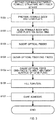
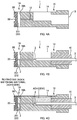
- Fig. 3 is a flowchart of a method for manufacturing (a procedure for assembling) the ferrule structure 1 with a fiber. Further, Figs. 4A to 4C are cross-sectional explanatory views illustrating states of respective steps.
- an operator prepares the ferrule body 10 and the lens plate 20 (S101). The operator also prepares the guide pins (not illustrated) for a next step. The operator also prepares a jig for assembling the ferrule body 10 and the lens plate 20 and the like as necessary.
- the operator aligns the ferrule body 10 with the lens plate 20 via the guide pins (S102).
- the operator inserts each guide pin (not illustrated) into both of the guide hole 11 of the ferrule body 10 and the guide hole 21 of the lens plate 20.
- the ferrule body 10 is aligned with the lens plate 20 in the up-down direction and the left-right direction.
- the operator brings the front end surface 10A of the ferrule body 10 into contact with the rear end surface 20B of the lens plate 20 while the guide pins are inserted. In this way, the ferrule body 10 is aligned with the lens plate 20 in the front-rear direction.
- a state where the front end surface 10A of the ferrule body 10 is in contact with the rear end surface 20B of the lens plate 20 may be maintained by placing, on a jig, the ferrule structure 1 in which the ferrule body 10 and the lens plate 20 are attached to each other via the guide pins (not illustrated).
- a positional relationship between the ferrule body 10 and the lens plate 20 is in a state illustrated in Figs. 1 and 4A (note that the guide pins are not illustrated).
- a gap is formed between the lens plate 20 and the ferrule body 10 with the recess 23 of the lens plate 20, and the matching material filling part 1A is formed with the gap.
- the bottom surface (abutment surface 231) of the recess 23 of the lens plate 20 faces the openings of the fiber holes 12 of the ferrule body 10.
- the operator inserts each of the optical fibers 3 of the optical fiber tape into each of the fiber holes 12 of the ferrule body 10 (S103) .
- the optical fiber 3 protrudes from the front end surface 10A (opening surface of the fiber hole 12) of the ferrule body 10.
- the optical fiber end-face does not abut the abutment surface 231 (bottom surface of the recess 23) of the lens plate 20. This is because dust and the like may adhere to the optical fiber end-face when the optical fiber 3 passes through the fiber hole 12.
- the operator cleans the optical fiber end-face (S104). For example, the operator blows air onto the gap of the matching material filling part 1A, and blows off dust adhering to the optical fiber end-face protruding from the front end surface 10A of the ferrule body 10. In this way, dust adhering on the optical fiber end-face when the optical fiber 3 is inserted into the fiber hole 12 (S103) can be removed.
- the cleaning processing in S104 is performed before S105 (abutment processing) and S106 (adhesive filling processing) in order to remove dust on the optical fiber end-face in such a manner.
- the operator further inserts the optical fiber 3, and causes the optical fiber end-face to abut the abutment surface 231 of the lens plate 20 (105) .
- an air layer may exist between the optical fiber end-face and the abutment surface 231.
- the operator inserts the boot 41 into the fiber insertion opening 13 in the present embodiment.
- the boot 41 may not be inserted into the fiber insertion opening 13.
- the operator fills the adhesive in the adhesive filling part 14 of the ferrule body 10.
- the adhesive is applied between the inner wall surface of the adhesive filling part 14 and the optical fiber 3.
- the adhesive permeates between the inner wall surface of the fiber hole 12 and the optical fiber 3.
- the adhesive filling the adhesive filling part 14 leaks from the front end surface 10A (opening of the fiber hole 12) of the ferrule body 10.
- a leak of the adhesive filling the adhesive filling part 14 from the front end surface 10A (openings of the fiber hole 12) of the ferrule body 10 is visible through a gap of the recess 23 (matching material filling part 1A) of the lens plate 20.
- the operator fills an adhesive to be a refractive index matching material in the matching material filling part 1A after recognizing a leak of the adhesive filling the adhesive filling part 14 from the front end surface 10A (opening of the fiber hole 12) of the ferrule body 10. This can suppress an air bubble remaining in the fiber hole 12.
- the operator fills the adhesive to be the refractive index matching material from the upper opening of the matching material filling part 1A.
- the refractive index matching material fills above the optical fibers 3 in the matching material filling part 1A, and then fills below the optical fibers 3 through a gap between the optical fibers 3, and permeates between the optical fiber end-face and the abutment part.
- the lower opening of the matching material filling part 1A functions as an air vent, and thus the refractive index matching material is more likely to reach the lower side of the optical fibers 3 and less likely to build up on the upper side of the optical fibers 3. Accordingly, filling time needed to fill the refractive index matching material in the matching material filling part 1A can be shortened.
- the adhesive to be the refractive index matching material fills the matching material filling part 1A in S106
- the adhesive permeates through a minute gap between contact surfaces of the ferrule body 10 and the lens plate 20.
- the ferrule body 10 and the lens plate 20 can be bonded and fixed together. This facilitates an operation of bonding and fixing the ferrule body 10 and the lens plate 20 together.
- the operator cures the adhesive (S107).
- an ultraviolet curing resin is used as the adhesive
- the operator applies ultraviolet rays.
- an ultraviolet curing resin is used as the adhesive, the operator applies heat.
- Fig. 5 is a cross-sectional explanatory view of the ferrule structure 1 according to a first modified example.
- the recess 23 is formed from the upper surface to the lower surface of the lens plate 20, and the matching material filling part 1A is opened in the upper surface and the lower surface of the ferrule structure 1.
- the recess 23 is formed only in an upper part of the lens plate 20, and the matching material filling part 1A is opened only in the upper surface of the ferrule structure 1.
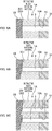
- Fig. 6A is an explanatory view of a vicinity of the optical fiber end-face according to the above-described embodiment.
- the abutment surface 231 of the lens plate 20 is a surface perpendicular to an optical axis (front-rear direction) of the optical fiber 3 in the above-described embodiment.
- a loss of an optical signal is more likely to occur due to reflection of the optical signal on the abutment surface 231.
- Fig. 6B is an explanatory view of a second modified example.
- the abutment surface 231 of the lens plate 20 is inclined to a surface perpendicular to the optical axis of the optical fiber 3 in the second modified example.
- the abutment surface 231 in Fig. 6B is inclined by about 8 degrees to the abutment surface 231 in Fig. 6A (the surface perpendicular to the optical axis of the optical fiber 3).
- This can suppress reflection of an optical signal on the abutment surface 231, and suppress a loss of the optical signal.
- an optical signal is refracted by the abutment surface 231, and thus a position in the up-down direction of each unit such as the fiber hole 12 with respect to the guide hole may be appropriately changed.
- Fig. 6C is another explanatory view of the second modified example.
- the fiber holes 12 of the ferrule body 10 are formed in one row, but the fiber holes 12 may be formed in two rows as illustrated in Fig. 6C .
- a position of an upper optical fiber end-face in the front-rear direction is different from a position of a lower optical fiber end-face in the front-rear direction, and thus an optical path length of an optical signal incident on and emitted from an upper optical fiber 3 (particularly, an optical path length from the optical fiber end-face to the lens part 22) is different from an optical path length of an optical signal incident on and emitted from a lower optical fiber 3.
- the abutment surface 231 being inclined may be formed in a multistage form by providing a step such that positions in the front-rear direction of endfaces of the optical fibers 3 arranged on the upper side and the lower side are aligned.
- the optical path lengths of the optical signals incident on and emitted from the optical fibers 3 arranged on the upper side and the lower side can be identical to each other.
- the above-described ferrule structure 1 includes the ferrule body 10 and the lens plate 20.
- the ferrule body 10 includes the guide hole(s) 11, the fiber hole(s) 12, and the opening surface (front end surface 10A) in which the fiber hole(s) 12 is opened.
- the lens plate 20 includes the guide hole(s) 21, the lens part(s) 22, and the abutment surface 231 for abutment of the optical fiber end-face(s).
- the recess 23 is formed in the lens plate 20, and a gap to be the matching material filling part 1A is formed with this recess 23, between the front end surface 10A (opening surface in which the fiber hole(s) 12 is opened) of the ferrule body 10 and the abutment surface 231 of the lens plate 20.
- the ferrule body 10 and the lens plate 20 can be constituted separately, and thus two parts of the guide hole(s) 11 and the fiber hole(s) 12 may be highly precisely formed in the ferrule body 10, and two parts of the guide hole(s) 21 and the lens part 22 may be highly precisely formed in the lens plate 20. This facilitates manufacturing of the ferrule body 10 and the lens plate 20.
- the optical fiber end-face may abut the abutment surface 231 and then the refractive index matching material may fill the matching material filling part 1A, and thus a polishing step of polishing the ferrule body 10 and the optical fiber end-face can be omitted. Accordingly, simplification of manufacturing steps can be achieved.
- the recess 23 is formed in the lens plate 20. If a recess is formed in the ferrule body 10, the recess is formed in the opening surface of the fiber hole(s) 12 that requires high positional precision, and thus molding of the ferrule body 10 is difficult. On the other hand, a shape of the ferrule body 10 can be simplified in this embodiment, and thus there is an advantage that resin molding of the ferrule body 10 is easy.
- a gap to be the matching material filling part 1A is formed between the opening surface of the fiber holes 12 of the ferrule body 10 and the abutment surface 231 of the lens plate 20.
- a gap to be the matching material filling part 1A may be formed between the opening surface of the fiber holes 12 of the ferrule body 10 and the abutment surface of the lens plate 20.
- Fig. 7A is a general perspective view of a ferrule structure 1 according to a second embodiment.
- Fig. 7B is an exploded perspective view of the ferrule structure 1 according to the second embodiment.
- a ferrule body 10 includes guide holes 11, fiber holes 12, a fiber insertion opening 13, and an adhesive filling part 14, similarly to the first embodiment, and also includes the recess 15.
- the recess 15 of the ferrule body 10 in the second embodiment is a part for forming a gap between opening surface of the fiber holes 12 of the ferrule body 10 and an abutment surface 20B of the lens plate 20, similarly to the recess 23 of the lens plate 20 in the first embodiment.
- the recess 15 is formed in a front end surface 10A of the ferrule body 10.
- the recess 15 is a part recessed from the front end surface 10A of the ferrule body 10.
- a bottom surface of the recess 15 is the opening surface in which the fiber holes 12 are opened.
- the bottom surface of the recess 15 being the opening surface of the fiber holes 12 faces a rear end surface 20B of the lens plate 20 to be an abutment surface for optical fibers 3.
- a width in the left-right direction of the bottom surface of the recess 15 is longer than a width of the row of the fiber holes 12 aligned in the left-right direction (longer than a width of the optical fiber tape).
- the recess 15 is formed in the ferrule body 10, and thus a gap is formed between the ferrule body 10 and the lens plate 20, and a matching material filling part 1A is formed with this gap.
- the recess 15 is formed from an upper surface to a lower surface in the front end surface 10A of the ferrule body 10.
- the matching material filling part 1A is opened in an upper surface and a lower surface of the ferrule structure 1.
- the recess 15 may be formed only in an upper part of the ferrule body 10, and the matching material filling part 1A may be opened only in the upper surface of the ferrule structure 1.
- the ferrule body 10 and the lens plate 20 can also be constituted separately in this second embodiment described above, two parts of the guide holes 11 and the fiber holes 12 may be highly precisely formed in the ferrule body 10, and two parts of guide holes 21 and a lens part 22 may be highly precisely formed in the lens plate 20. This facilitates manufacturing of the ferrule body 10 and the lens plate 20. Also in the second embodiment, since an optical fiber end-face may abut the abutment surface 231 and then a refractive index matching material may fill the matching material filling part 1A, a polishing step of polishing the ferrule body 10 and the optical fiber end-face can be omitted. Accordingly, simplification of manufacturing steps can be achieved.
- a recess may be formed in both of the ferrule body 10 and the lens plate 20 instead of being formed in only one of the ferrule body 10 and the lens plate 20. Even in such a case, a gap is formed between the ferrule body 10 and the lens plate 20, and the matching material filling part 1A can be formed with the gap.
Landscapes
- Physics & Mathematics (AREA)
- General Physics & Mathematics (AREA)
- Optics & Photonics (AREA)
- Optical Couplings Of Light Guides (AREA)
- Mechanical Coupling Of Light Guides (AREA)
Abstract


Description
- The present invention relates to a ferrule structure, a ferrule structure with a fiber, and a method for manufacturing a ferrule structure with a fiber.
- As a ferrule that holds an end part of an optical fiber, a ferrule is known that includes an adhesive filling part provided with an opening for filling an adhesive, to fix an optical fiber by filling an adhesive in the adhesive filling part.
Patent Literature 1 discloses that an endface of an optical fiber abuts an inner wall of an adhesive filling part (recess part) of a ferrule, and an adhesive fills from an opening of the adhesive filling part, and the adhesive is cured to fix the optical fiber. - Further, a configuration is known in which a ferrule body holding an end part of an optical fiber is constituted separately from a lens array. Patent Literature 2 discloses that a front surface of a ferrule body and an endface of an optical fiber are polished, and then a lens array is attached to the front surface of the ferrule body.
-
- Patent Literature 1:
JP 5564344B - Patent Literature 2:
JP 2014-521996A - When a ferrule is integrally constituted like the ferrule described in
Patent Literature 1 and a lens is arranged in an optical path of an optical signal, three parts of a fiber hole related to a position of an endface of an optical fiber, the lens, and a guide pin hole need to be formed in a highly precise positional relationship with each other. However, in order to form all of these three parts highly precisely at the same timing, manufacturing of the ferrule is difficult, and the ferrule becomes expensive. - When a ferrule body and a lens array are separately constituted like the ferrule described in Patent Literature 2, two parts of a fiber hole and a guide pin hole may need to be highly precisely formed in the ferrule body, and two parts of a lens and a guide pin hole may be highly precisely formed in the lens array, which facilitates manufacturing of the ferrule body and the lens array. However, according to a method for manufacturing a ferrule described in Patent Literature 2, a front surface of a ferrule body and an endface of an optical fiber need to be polished, and thus a polishing step is needed.
- An objective of some embodiments of the present invention is to separately constitute a ferrule body and a lens array, and also allow a polishing step to be omitted, and thus achieve simplification of manufacturing steps.
- Some embodiments of the present invention is a ferrule structure including: a ferrule body including a guide hole for insertion of a guide pin, a fiber hole for insertion of an optical fiber, and an opening surface in which the fiber hole is opened; and a lens plate including a guide hole for insertion of the guide pin, a lens part, and an abutment surface for abutment of an endface of the optical fiber, wherein a recess is formed in at least one of the ferrule body and the lens plate, and a gap to be a matching material filling part that is to be filled with a refractive index matching material is formed with the recess, between the opening surface of the ferrule body and the abutment surface of the lens plate.
- Other features of the invention are made clear by the following description and the drawings.
- According to some embodiments of the present invention, a ferrule body and a lens array are separately constituted, and a polishing step can also be omitted, and thus simplification of manufacturing steps can be achieved.
-
-
Fig. 1 is a general perspective view of aferrule structure 1 according to a first embodiment. -
Figs. 2A and 2B are exploded perspective views of theferrule structure 1 according to the first embodiment. -
Fig. 3 is a flowchart of a method for manufacturing (a procedure for assembling) theferrule structure 1 with a fiber. -
Figs. 4A to 4C are cross-sectional explanatory views illustrating states of manufacturing steps. -
Fig. 5 is a cross-sectional explanatory view of theferrule structure 1 according to a first modified example. -
Fig. 6A is an explanatory view of a vicinity of an optical fiber end-face according to the first embodiment.Fig. 6B is an explanatory view of a second modified example.Fig. 6C is another explanatory view of the second modified example. -
Fig. 7A is a general perspective view of aferrule structure 1 according to a second embodiment.Fig. 7B is an exploded perspective view of theferrule structure 1 according to the second embodiment. - At least the following matters are made clear from the following description and the drawings.
- A ferrule structure will become clear including: a ferrule body including a guide hole for insertion of a guide pin, a fiber hole for insertion of an optical fiber, and an opening surface in which the fiber hole is opened; and a lens plate including a guide hole for insertion of the guide pin, a lens part, and an abutment surface for abutment of an endface of the optical fiber, wherein a recess is formed in at least one of the ferrule body and the lens plate, and a gap to be a matching material filling part that is to be filled with a refractive index matching material is formed with the recess, between the opening surface of the ferrule body and the abutment surface of the lens plate. With this ferrule structure, the ferrule body and the lens array are separately constituted, and a polishing step can also be omitted, and thus simplification of manufacturing steps can be achieved.
- The recess is preferably formed in the lens plate. In this way, it is possible to simplify a shape of the ferrule body.
- The recess is preferably formed from an upper part to a lower part such that the matching material filling part is opened in an upper surface and a lower surface. In this way, it is possible to facilitate a filling operation of filling a refractive index matching material in the matching material filling part.
- The abutment surface is preferably a surface inclined to a surface perpendicular to an optical axis of the optical fiber. In this way, it is possible to suppress a loss of an optical signal.
- The ferrule body preferably includes a plurality of the fiber holes formed in at least two rows; and the abutment surface is preferably formed in a multistage form such that positions of endfaces of optical fibers in an optical axis direction are aligned. In this way, optical path lengths of optical signals of respective optical fibers can be identical to each other.
- A ferrule structure with a fiber will become clear including: an optical fiber; a ferrule body including a guide hole for insertion of a guide pin, a fiber hole in which the optical fiber is inserted, and an opening surface in which the fiber hole is opened; and a lens plate including a guide hole for insertion of the guide pin, a lens part, and an abutment surface abutted with an endface of the optical fiber, wherein a recess is formed in at least one of the ferrule body and the lens plate, and a refractive index matching material fills a gap formed with the recess, between the opening surface of the ferrule body and the abutment surface of the lens plate. With this ferrule structure with a fiber, the ferrule body and the lens array are separately constituted, and a polishing step can also be omitted, and thus simplification of manufacturing steps can be achieved.
- The refractive index matching material is preferably made of an adhesive; and the ferrule body and the lens plate are preferably bonded and fixed together with the refractive index matching material filling the gap. In this way, it is possible to facilitate an operation of bonding and fixing the ferrule body and the lens plate together.
- A method for manufacturing a ferrule structure with a fiber will become clear, the method including: (1) preparing a ferrule body including a guide hole for insertion of a guide pin, a fiber hole for insertion of an optical fiber, and an opening surface in which the fiber hole is opened, and a lens plate including a guide hole for insertion of the guide pin, a lens part, and an abutment surface for abutment of an endface of the optical fiber; (2) forming, with a recess formed in at least one of the ferrule body and the lens plate, a gap to be a matching material filling part between the opening surface of the ferrule body and the abutment surface of the lens plate by bringing the ferrule body into contact with the lens plate while aligning the ferrule body with the lens plate via the guide pin; (3) causing an endface of the optical fiber to abut the abutment surface of the lens plate by inserting the optical fiber into the fiber hole; and (4) filling a refractive index matching material in the matching material filling part. With this manufacturing method, the ferrule body and the lens array are separately constituted, and a polishing step can also be omitted, and thus simplification of the manufacturing steps can be achieved.
-
Fig. 1 is a general perspective view of aferrule structure 1 according to a first embodiment.Figs. 2A and 2B are exploded perspective views of theferrule structure 1 according to the first embodiment. - In the following description, directions will be defined as illustrated in the drawings. Specifically, a direction of a
fiber hole 12 is a "front-rear direction", an endface side of an optical fiber 3 (cf.Figs. 4B and 4C ) inserted in the fiber hole 12 (or alens plate 20 side seen from a ferrule body 10) is "front", and an opposite side is "rear". Further, a direction in which twoguide holes 21 are aligned is a "left-right direction", a right side when a front side is seen from a rear side is "right", and an opposite side is "left". Further, a direction perpendicular to the front-rear direction and the left-right direction is an "up-down direction", an opening side for filling an adhesive in an adhesive fillingpart 14 is "up", and an opposite side is "down". - The
ferrule structure 1 is a member for holding an end part of theoptical fiber 3 and optically connecting theoptical fiber 3 to another optical component. Theferrule structure 1 may be simply referred to as a "ferrule". Theferrule structure 1 includes theferrule body 10 and thelens plate 20. - The
ferrule body 10 is a member that holds the end part of theoptical fiber 3. Theferrule body 10 includes guide holes 11, fiber holes 12, afiber insertion opening 13, and the adhesive fillingpart 14. - Note that, the
ferrule body 10 has a configuration substantially similar to that of a mechanically transferable (MT) optical connector (F12 optical connector established by JIS C5981), for example. However, while a ferrule endface and an optical fiber end-face are polished in a normal MT optical connector, an optical fiber end-face protrudes from afront end surface 10A of the ferrule body 10 (opening surface of the fiber hole 12) and a ferrule endface and the optical fiber end-face are not polished in the present embodiment, as described later. Further, while a fiber end-face is exposed from the ferrule endface in the normal MT optical connector, the optical fiber end-face is not exposed to the outside because thelens plate 20 is arranged on a front side of theferrule body 10 and the optical fiber end-face abuts thelens plate 20 in the present embodiment. - Each of the guide holes 11 is a hole for insertion of a guide pin (not illustrated) . As described later, the guide holes 11 are also used for aligning the
ferrule body 10 with thelens plate 20. The guide holes 11 penetrate theferrule body 10 along the front-rear direction. Two guide holes 11 are opened in thefront end surface 10A of theferrule body 10. The twoguide holes 11 are arranged at an interval in the left-right direction so as to sandwich a plurality of the fiber holes 12 in the left-right direction. - The fiber holes 12 are holes for insertion of the optical fibers 3 (cf.
Figs. 4B and 4C ). The fiber holes 12 are also holes for positioning theoptical fibers 3. Thus, the fiber holes 12 are highly precisely formed with respect to the guide holes 11. The fiber holes 12 penetrate between thefront end surface 10A and the adhesive fillingpart 14. The fiber holes 12 are opened in thefront end surface 10A of theferrule body 10. A bare optical fiber in which a sheath is removed from a coated optical fiber is inserted in eachfiber hole 12. The fiber holes 12 are formed along the front-rear direction. - The plurality of fiber holes 12 are formed in the
ferrule body 10. The plurality of fiber holes 12 are aligned in the left-right direction. Theoptical fibers 3 constituting an optical fiber tape (optical fiber ribbon) are inserted in respective fiber holes 12 aligned in the left-right direction. In the present embodiment, one row of the fiber holes 12 aligned in the left-right direction is provided. The fiber holes 12 may have one or a plurality of rows. - The
fiber insertion opening 13 is an opening formed in a rear endface of theferrule body 10. The optical fibers 3 (cf.Figs. 4B and 4C ) are to be inserted into theferrule body 10 from thefiber insertion opening 13. A boot 41 (cf.Figs. 4B and 4C ) may be inserted in thefiber insertion opening 13, and thus thefiber insertion opening 13 may be referred to as a "boot hole". - The adhesive filling
part 14 is a hollow part to be filled with an adhesive. An adhesive for keeping theoptical fibers 3 in theferrule body 10 fills the adhesive fillingpart 14. The adhesive fills the adhesive fillingpart 14, and is thus applied between inner wall surfaces of the adhesive fillingpart 14 and thefiber hole 12, and theoptical fiber 3. This adhesive is cured to fix theoptical fiber 3 to theferrule body 10. - The
lens plate 20 is an optical member including a lens array in which a plurality of lenses are aligned. Thelens plate 20 is molded from transparent resin that allows transmission of an optical signal. Thelens plate 20 is arranged on the front side of theferrule body 10 while arear end surface 20B of thelens plate 20 is in contact with thefront end surface 10A of theferrule body 10. Thelens plate 20 includes the guide holes 21,lens parts 22, and arecess 23. - Each of the guide holes 21 is a hole for insertion of a guide pin (not illustrated) . The guide pin is inserted in each
guide hole 21, and thusferrule structures 1 are aligned with each other. Note that, as described later, the guide holes 21 are also used for aligning theferrule body 10 with thelens plate 20. Thus, an interval between the two guide holes 21 is the same as an interval between the twoguide holes 11 of theferrule body 10. The guide holes 21 penetrate thelens plate 20 along the front-rear direction. The twoguide holes 21 are opened in each of thefront end surface 20A and therear end surface 20B of thelens plate 20. - The
lens part 22 is arranged so as to correspond to each of the plurality of optical fibers 3 (in other words, the plurality of fiber holes 12), and an optical signal is input and output via thelens part 22. Thus, thelens part 22 is highly precisely formed with respect to the guide holes 21. Thelens part 22 is formed so as to function as, for example, a collimating lens. A transmission loss of an optical signal can be suppressed by inputting and outputting the optical signal having a diameter magnified by thelens part 22. Thelens part 22 is formed on thefront end surface 20A side of thelens plate 20 and is formed in thefront end surface 20A of theferrule structure 1. Thelens part 22 is formed on a bottom part of arecess part 221 of thelens plate 20 such that the protrudinglens parts 22 do not contact each other when theferrule structures 1 face and abut each other. - The
recess 23 is a part for forming a gap between the opening surface of the fiber holes 12 of theferrule body 10 and an abutment surface 231 (abutment surface 231 for abutment of the optical fiber end-faces) of thelens plate 20. In the present embodiment, therecess 23 is formed in therear end surface 20B of thelens plate 20. In other words, in the present embodiment, therecess 23 is a part recessed from therear end surface 20B of thelens plate 20. A bottom surface of therecess 23 is theabutment surface 231 for abutment of the optical fiber end-faces. Thus, when thelens plate 20 is attached to theferrule body 10 via the guide pins (not illustrated) (described later), the bottom surface of therecess 23 being theabutment surface 231 faces the opening of the fiber holes 12 of theferrule body 10. Note that a width in the left-right direction of the bottom surface of therecess 23 is longer than a width of the row of the fiber holes 12 aligned in the left-right direction (longer than a width of the optical fiber tape). - The
recess 23 is formed in thelens plate 20, and thus a gap is formed between thelens plate 20 and theferrule body 10, and a matchingmaterial filling part 1A is formed with the gap. In the present embodiment, therecess 23 is formed from an upper surface to a lower surface of thelens plate 20. Thus, the matchingmaterial filling part 1A is opened in the upper surface and the lower surface of theferrule structure 1. - The matching
material filling part 1A is a hollow part to be filled with a refractive index matching material. The matchingmaterial filling part 1A is filled with an adhesive including a function as a refractive index matching material, but an adhesive may not be used as long as a refractive index matching material is used. The matchingmaterial filling part 1A is formed to be longer than a width of the optical fiber tape (optical fiber ribbon) in the left-right direction. - An upper opening of the matching
material filling part 1A includes a function as an input port for inputting a refractive index matching material to the matchingmaterial filling part 1A. A lower opening of the matchingmaterial filling part 1A includes a function as an air vent for ventilation between the matchingmaterial filling part 1A and the outside. Note that the lower side of the matchingmaterial filling part 1A may not be opened, and only the upper side thereof may be opened. However, in this case, a refractive index matching material is more likely to build up on the upper side of theoptical fibers 3. As a result, the refractive index matching material is less likely to reach a bottom surface of the matchingmaterial filling part 1A, and an air bubble is more likely to be formed in the matchingmaterial filling part 1A (thus, an air layer (air bubble) is more likely to be formed on the endface of theoptical fiber 3, and a loss of an optical signal may be increased). - Further, as in the present embodiment, the
recess 23 is formed from the upper surface to the lower surface of thelens plate 20, and the matchingmaterial filling part 1A is configured to be opened in the upper surface and the lower surface of theferrule structure 1. Thus, the matchingmaterial filling part 1A has a substantially vertically symmetrical structure. This results in an advantage that deformation such as a warp in theferrule structure 1 can be suppressed when a refractive index matching material (adhesive) filling the matchingmaterial filling part 1A is cured and contracts. Note that, in a case where the matchingmaterial filling part 1A is opened only on the upper side, when a refractive index matching material (adhesive) is cured and contracts, deformation occurs on the upper side on which the matchingmaterial filling part 1A is opened in such a way as to reduce the gap between theferrule body 10 and thelens plate 20, and deformation does not occur on the lower side. As a result, deformation may occur in such a way that theferrule structure 1 is warped. -
Fig. 3 is a flowchart of a method for manufacturing (a procedure for assembling) theferrule structure 1 with a fiber. Further,Figs. 4A to 4C are cross-sectional explanatory views illustrating states of respective steps. - First, an operator prepares the
ferrule body 10 and the lens plate 20 (S101). The operator also prepares the guide pins (not illustrated) for a next step. The operator also prepares a jig for assembling theferrule body 10 and thelens plate 20 and the like as necessary. - Next, the operator aligns the
ferrule body 10 with thelens plate 20 via the guide pins (S102). At this time, the operator inserts each guide pin (not illustrated) into both of theguide hole 11 of theferrule body 10 and theguide hole 21 of thelens plate 20. In this way, theferrule body 10 is aligned with thelens plate 20 in the up-down direction and the left-right direction. Further, the operator brings thefront end surface 10A of theferrule body 10 into contact with therear end surface 20B of thelens plate 20 while the guide pins are inserted. In this way, theferrule body 10 is aligned with thelens plate 20 in the front-rear direction. Note that a state where thefront end surface 10A of theferrule body 10 is in contact with therear end surface 20B of thelens plate 20 may be maintained by placing, on a jig, theferrule structure 1 in which theferrule body 10 and thelens plate 20 are attached to each other via the guide pins (not illustrated). - When the
ferrule body 10 is aligned with thelens plate 20 in S102, a positional relationship between theferrule body 10 and thelens plate 20 is in a state illustrated inFigs. 1 and4A (note that the guide pins are not illustrated). At this time, a gap is formed between thelens plate 20 and theferrule body 10 with therecess 23 of thelens plate 20, and the matchingmaterial filling part 1A is formed with the gap. The bottom surface (abutment surface 231) of therecess 23 of thelens plate 20 faces the openings of the fiber holes 12 of theferrule body 10. - Next, the operator inserts each of the
optical fibers 3 of the optical fiber tape into each of the fiber holes 12 of the ferrule body 10 (S103) . Then, theoptical fiber 3 protrudes from thefront end surface 10A (opening surface of the fiber hole 12) of theferrule body 10. However, in this stage, the optical fiber end-face does not abut the abutment surface 231 (bottom surface of the recess 23) of thelens plate 20. This is because dust and the like may adhere to the optical fiber end-face when theoptical fiber 3 passes through thefiber hole 12. - Next, the operator cleans the optical fiber end-face (S104). For example, the operator blows air onto the gap of the matching
material filling part 1A, and blows off dust adhering to the optical fiber end-face protruding from thefront end surface 10A of theferrule body 10. In this way, dust adhering on the optical fiber end-face when theoptical fiber 3 is inserted into the fiber hole 12 (S103) can be removed. Note that the cleaning processing in S104 is performed before S105 (abutment processing) and S106 (adhesive filling processing) in order to remove dust on the optical fiber end-face in such a manner. - Next, the operator further inserts the
optical fiber 3, and causes the optical fiber end-face to abut theabutment surface 231 of the lens plate 20 (105) . In this stage, strictly speaking, an air layer may exist between the optical fiber end-face and theabutment surface 231. Note that, as illustrated inFig. 4B , the operator inserts theboot 41 into thefiber insertion opening 13 in the present embodiment. However, theboot 41 may not be inserted into thefiber insertion opening 13. - Next, the operator fills an adhesive (S106).
- In the adhesive filling processing in S106, first, the operator fills the adhesive in the adhesive filling
part 14 of theferrule body 10. In this way, the adhesive is applied between the inner wall surface of the adhesive fillingpart 14 and theoptical fiber 3. Further, when the adhesive fills the adhesive fillingpart 14, the adhesive permeates between the inner wall surface of thefiber hole 12 and theoptical fiber 3. When the adhesive sufficiently permeates, the adhesive filling the adhesive fillingpart 14 leaks from thefront end surface 10A (opening of the fiber hole 12) of theferrule body 10. In the present embodiment, a leak of the adhesive filling the adhesive fillingpart 14 from thefront end surface 10A (openings of the fiber hole 12) of theferrule body 10 is visible through a gap of the recess 23 (matchingmaterial filling part 1A) of thelens plate 20. The operator fills an adhesive to be a refractive index matching material in the matchingmaterial filling part 1A after recognizing a leak of the adhesive filling the adhesive fillingpart 14 from thefront end surface 10A (opening of the fiber hole 12) of theferrule body 10. This can suppress an air bubble remaining in thefiber hole 12. - The operator fills the adhesive to be the refractive index matching material from the upper opening of the matching
material filling part 1A. At this time, the refractive index matching material fills above theoptical fibers 3 in the matchingmaterial filling part 1A, and then fills below theoptical fibers 3 through a gap between theoptical fibers 3, and permeates between the optical fiber end-face and the abutment part. At this time, the lower opening of the matchingmaterial filling part 1A functions as an air vent, and thus the refractive index matching material is more likely to reach the lower side of theoptical fibers 3 and less likely to build up on the upper side of theoptical fibers 3. Accordingly, filling time needed to fill the refractive index matching material in the matchingmaterial filling part 1A can be shortened. - When the adhesive to be the refractive index matching material fills the matching
material filling part 1A in S106, the adhesive permeates through a minute gap between contact surfaces of theferrule body 10 and thelens plate 20. In this way, when the adhesive is cured in next processing, theferrule body 10 and thelens plate 20 can be bonded and fixed together. This facilitates an operation of bonding and fixing theferrule body 10 and thelens plate 20 together. - Next, the operator cures the adhesive (S107). When an ultraviolet curing resin is used as the adhesive, the operator applies ultraviolet rays. Alternatively, when an ultraviolet curing resin is used as the adhesive, the operator applies heat.
-
Fig. 5 is a cross-sectional explanatory view of theferrule structure 1 according to a first modified example. In the above-described embodiment, therecess 23 is formed from the upper surface to the lower surface of thelens plate 20, and the matchingmaterial filling part 1A is opened in the upper surface and the lower surface of theferrule structure 1. In contrast, in the first modified example, therecess 23 is formed only in an upper part of thelens plate 20, and the matchingmaterial filling part 1A is opened only in the upper surface of theferrule structure 1. -
Fig. 6A is an explanatory view of a vicinity of the optical fiber end-face according to the above-described embodiment. As illustrated inFig. 6A , theabutment surface 231 of thelens plate 20 is a surface perpendicular to an optical axis (front-rear direction) of theoptical fiber 3 in the above-described embodiment. However, in this case, a loss of an optical signal is more likely to occur due to reflection of the optical signal on theabutment surface 231. -
Fig. 6B is an explanatory view of a second modified example. As illustrated inFig. 6B , theabutment surface 231 of thelens plate 20 is inclined to a surface perpendicular to the optical axis of theoptical fiber 3 in the second modified example. For example, theabutment surface 231 inFig. 6B is inclined by about 8 degrees to theabutment surface 231 inFig. 6A (the surface perpendicular to the optical axis of the optical fiber 3). This can suppress reflection of an optical signal on theabutment surface 231, and suppress a loss of the optical signal. Note that, when theabutment surface 231 is inclined, an optical signal is refracted by theabutment surface 231, and thus a position in the up-down direction of each unit such as thefiber hole 12 with respect to the guide hole may be appropriately changed. -
Fig. 6C is another explanatory view of the second modified example. In the above-described embodiment, the fiber holes 12 of theferrule body 10 are formed in one row, but the fiber holes 12 may be formed in two rows as illustrated inFig. 6C . When the optical fiber end-faces abut a singleinclined abutment surface 231 in such a case, a position of an upper optical fiber end-face in the front-rear direction is different from a position of a lower optical fiber end-face in the front-rear direction, and thus an optical path length of an optical signal incident on and emitted from an upper optical fiber 3 (particularly, an optical path length from the optical fiber end-face to the lens part 22) is different from an optical path length of an optical signal incident on and emitted from a loweroptical fiber 3. Thus, as illustrated inFig. 6C , theabutment surface 231 being inclined may be formed in a multistage form by providing a step such that positions in the front-rear direction of endfaces of theoptical fibers 3 arranged on the upper side and the lower side are aligned. In this way, the optical path lengths of the optical signals incident on and emitted from theoptical fibers 3 arranged on the upper side and the lower side can be identical to each other. - The above-described
ferrule structure 1 includes theferrule body 10 and thelens plate 20. Theferrule body 10 includes the guide hole(s) 11, the fiber hole(s) 12, and the opening surface (front end surface 10A) in which the fiber hole(s) 12 is opened. Thelens plate 20 includes the guide hole(s) 21, the lens part(s) 22, and theabutment surface 231 for abutment of the optical fiber end-face(s). In the present embodiment, therecess 23 is formed in thelens plate 20, and a gap to be the matchingmaterial filling part 1A is formed with thisrecess 23, between thefront end surface 10A (opening surface in which the fiber hole(s) 12 is opened) of theferrule body 10 and theabutment surface 231 of thelens plate 20. With thisferrule structure 1 in this embodiment, theferrule body 10 and thelens plate 20 can be constituted separately, and thus two parts of the guide hole(s) 11 and the fiber hole(s) 12 may be highly precisely formed in theferrule body 10, and two parts of the guide hole(s) 21 and thelens part 22 may be highly precisely formed in thelens plate 20. This facilitates manufacturing of theferrule body 10 and thelens plate 20. Further, with theferrule structure 1 in this embodiment, the optical fiber end-face may abut theabutment surface 231 and then the refractive index matching material may fill the matchingmaterial filling part 1A, and thus a polishing step of polishing theferrule body 10 and the optical fiber end-face can be omitted. Accordingly, simplification of manufacturing steps can be achieved. - Further, with the
ferrule structure 1 in this embodiment, therecess 23 is formed in thelens plate 20. If a recess is formed in theferrule body 10, the recess is formed in the opening surface of the fiber hole(s) 12 that requires high positional precision, and thus molding of theferrule body 10 is difficult. On the other hand, a shape of theferrule body 10 can be simplified in this embodiment, and thus there is an advantage that resin molding of theferrule body 10 is easy. - In the first embodiment described above, by forming the
recess 23 in thelens plate 20, a gap to be the matchingmaterial filling part 1A is formed between the opening surface of the fiber holes 12 of theferrule body 10 and theabutment surface 231 of thelens plate 20. However, by forming arecess 15 in theferrule body 10, a gap to be the matchingmaterial filling part 1A may be formed between the opening surface of the fiber holes 12 of theferrule body 10 and the abutment surface of thelens plate 20. -
Fig. 7A is a general perspective view of aferrule structure 1 according to a second embodiment.Fig. 7B is an exploded perspective view of theferrule structure 1 according to the second embodiment. - A
ferrule body 10 includes guide holes 11, fiber holes 12, afiber insertion opening 13, and an adhesive fillingpart 14, similarly to the first embodiment, and also includes therecess 15. - The
recess 15 of theferrule body 10 in the second embodiment is a part for forming a gap between opening surface of the fiber holes 12 of theferrule body 10 and anabutment surface 20B of thelens plate 20, similarly to therecess 23 of thelens plate 20 in the first embodiment. In the second embodiment, therecess 15 is formed in afront end surface 10A of theferrule body 10. In other words, in the second embodiment, therecess 15 is a part recessed from thefront end surface 10A of theferrule body 10. A bottom surface of therecess 15 is the opening surface in which the fiber holes 12 are opened. Thus, when thelens plate 20 is attached to theferrule body 10 via guide pins (not illustrated) (cf.Fig. 7A ), the bottom surface of therecess 15 being the opening surface of the fiber holes 12 faces arear end surface 20B of thelens plate 20 to be an abutment surface foroptical fibers 3. Note that, also in the second embodiment, a width in the left-right direction of the bottom surface of therecess 15 is longer than a width of the row of the fiber holes 12 aligned in the left-right direction (longer than a width of the optical fiber tape). - The
recess 15 is formed in theferrule body 10, and thus a gap is formed between theferrule body 10 and thelens plate 20, and a matchingmaterial filling part 1A is formed with this gap. In this embodiment, therecess 15 is formed from an upper surface to a lower surface in thefront end surface 10A of theferrule body 10. Thus, also in the second embodiment, the matchingmaterial filling part 1A is opened in an upper surface and a lower surface of theferrule structure 1. However, therecess 15 may be formed only in an upper part of theferrule body 10, and the matchingmaterial filling part 1A may be opened only in the upper surface of theferrule structure 1. - Since the
ferrule body 10 and thelens plate 20 can also be constituted separately in this second embodiment described above, two parts of the guide holes 11 and the fiber holes 12 may be highly precisely formed in theferrule body 10, and two parts of guide holes 21 and alens part 22 may be highly precisely formed in thelens plate 20. This facilitates manufacturing of theferrule body 10 and thelens plate 20. Also in the second embodiment, since an optical fiber end-face may abut theabutment surface 231 and then a refractive index matching material may fill the matchingmaterial filling part 1A, a polishing step of polishing theferrule body 10 and the optical fiber end-face can be omitted. Accordingly, simplification of manufacturing steps can be achieved. - Note that a recess may be formed in both of the
ferrule body 10 and thelens plate 20 instead of being formed in only one of theferrule body 10 and thelens plate 20. Even in such a case, a gap is formed between theferrule body 10 and thelens plate 20, and the matchingmaterial filling part 1A can be formed with the gap. - The foregoing embodiments are for facilitating the understanding of the present invention, and are not to be construed as limiting this invention. The present invention may be modified and/or improved without departing from the gist thereof, and it goes without saying that this invention encompasses any equivalents thereof.
-
- 1:
- Ferrule structure;
- 1A:
- Matching material filling part;
- 3:
- Optical fiber;
- 10:
- Ferrule body;
- 10A:
- Front end surface;
- 11:
- Guide hole;
- 12:
- Fiber hole;
- 13:
- Fiber insertion opening;
- 14:
- Adhesive filling part;
- 15:
- Recess;
- 20:
- Lens plate;
- 20A:
- Front end surface;
- 20B:
- Rear end surface (abutment surface in second embodiment);
- 21:
- Guide hole;
- 22:
- Lens part;
- 221:
- Recess part;
- 23:
- Recess;
- 231:
- Abutment surface;
- 41:
- Boot.
Claims (8)
- A ferrule structure comprising:a ferrule body including a guide hole for insertion of a guide pin, a fiber hole for insertion of an optical fiber, and an opening surface in which the fiber hole is opened; anda lens plate including a guide hole for insertion of the guide pin, a lens part, and an abutment surface for abutment of an endface of the optical fiber, whereina recess is formed in at least one of the ferrule body and the lens plate, anda gap to be a matching material filling part that is to be filled with a refractive index matching material is formed with the recess, between the opening surface of the ferrule body and the abutment surface of the lens plate.
- The ferrule structure according to claim 1, wherein the recess is formed in the lens plate.
- The ferrule structure according to claim 1 or 2, wherein the recess is formed from an upper part to a lower part such that the matching material filling part is opened in an upper surface and a lower surface.
- The ferrule structure according to any one of claims 1 to 3, wherein the abutment surface is a surface inclined to a surface perpendicular to an optical axis of the optical fiber.
- The ferrule structure according to claim 4, wherein:the ferrule body includes a plurality of the fiber holes formed in at least two rows; andthe abutment surface is formed in a multistage form such that positions of endfaces of optical fibers in an optical axis direction are aligned.
- A ferrule structure with a fiber comprising:an optical fiber;a ferrule body including a guide hole for insertion of a guide pin, a fiber hole in which the optical fiber is inserted, and an opening surface in which the fiber hole is opened; anda lens plate including a guide hole for insertion of the guide pin, a lens part, and an abutment surface abutted with an endface of the optical fiber, whereina recess is formed in at least one of the ferrule body and the lens plate, anda refractive index matching material fills a gap formed with the recess, between the opening surface of the ferrule body and the abutment surface of the lens plate.
- The ferrule structure with a fiber according to claim 6, wherein:the refractive index matching material is made of an adhesive; andthe ferrule body and the lens plate are bonded and fixed together with the refractive index matching material filling the gap.
- A method for manufacturing a ferrule structure with a fiber, the method comprising:(1) preparinga ferrule body including a guide hole for insertion of a guide pin, a fiber hole for insertion of an optical fiber, and an opening surface in which the fiber hole is opened, anda lens plate including a guide hole for insertion of the guide pin, a lens part, and an abutment surface for abutment of an endface of the optical fiber;(2) forming, with a recess formed in at least one of the ferrule body and the lens plate, a gap to be a matching material filling part between the opening surface of the ferrule body and the abutment surface of the lens plate by bringing the ferrule body into contact with the lens plate while aligning the ferrule body with the lens plate via the guide pin;(3) causing an endface of the optical fiber to abut the abutment surface of the lens plate by inserting the optical fiber into the fiber hole; and(4) filling a refractive index matching material in the matching material filling part.
Applications Claiming Priority (2)
| Application Number | Priority Date | Filing Date | Title |
|---|---|---|---|
| JP2016232508 | 2016-11-30 | ||
| PCT/JP2017/042744 WO2018101302A1 (en) | 2016-11-30 | 2017-11-29 | Ferrule structure, ferrule structure with fiber, and method for manufacturing ferrule structure with fiber |
Publications (2)
| Publication Number | Publication Date |
|---|---|
| EP3525020A1 true EP3525020A1 (en) | 2019-08-14 |
| EP3525020A4 EP3525020A4 (en) | 2020-06-03 |
Family
ID=62242141
Family Applications (1)
| Application Number | Title | Priority Date | Filing Date |
|---|---|---|---|
| EP17875277.0A Withdrawn EP3525020A4 (en) | 2016-11-30 | 2017-11-29 | Ferrule structure, ferrule structure with fiber, and method for manufacturing ferrule structure with fiber |
Country Status (5)
| Country | Link |
|---|---|
| US (1) | US10705299B2 (en) |
| EP (1) | EP3525020A4 (en) |
| JP (1) | JP2018092152A (en) |
| CN (1) | CN109923452A (en) |
| WO (1) | WO2018101302A1 (en) |
Cited By (2)
| Publication number | Priority date | Publication date | Assignee | Title |
|---|---|---|---|---|
| US10585248B2 (en) | 2017-02-20 | 2020-03-10 | Us Conec, Ltd. | Lensed ferrule with low back reflection |
| US12147079B2 (en) | 2019-04-24 | 2024-11-19 | Us Conec Ltd. | Lens plate for ferrules |
Families Citing this family (13)
| Publication number | Priority date | Publication date | Assignee | Title |
|---|---|---|---|---|
| JP6401888B1 (en) * | 2017-06-16 | 2018-10-10 | 京セラ株式会社 | Optical connector module |
| JP1598020S (en) * | 2017-08-02 | 2018-02-19 | ||
| WO2019244388A1 (en) * | 2018-06-20 | 2019-12-26 | 住友電気工業株式会社 | Optical connection component, optical connector and optical connection structure |
| JP7096525B2 (en) * | 2018-07-06 | 2022-07-06 | コニカミノルタ株式会社 | Lens array element and fiber optic connector |
| WO2020105258A1 (en) * | 2018-11-22 | 2020-05-28 | 株式会社フジクラ | Ferrule, fiber-attached ferrule, and method for manufacturing fiber-attached ferrule |
| JP7198155B2 (en) * | 2018-11-22 | 2022-12-28 | 株式会社フジクラ | Ferrule, ferrule with fiber, and method for manufacturing ferrule with fiber |
| WO2020121619A1 (en) * | 2018-12-10 | 2020-06-18 | 株式会社フジクラ | Ferrule and fiber-equipped ferrule |
| WO2020121618A1 (en) | 2018-12-14 | 2020-06-18 | 株式会社フジクラ | Ferrule, ferrule provided with fiber, and method for manufacturing ferrule provided with fiber |
| JP6864666B2 (en) * | 2018-12-25 | 2021-04-28 | 株式会社フジクラ | Connector system, optical connection method and optical connection member |
| JP2020160350A (en) * | 2019-03-27 | 2020-10-01 | 住友電気工業株式会社 | Optical connector ferrule and optical connector |
| WO2022065023A1 (en) * | 2020-09-25 | 2022-03-31 | 住友電気工業株式会社 | Ferrule and optical connector |
| JP2023125669A (en) * | 2022-02-28 | 2023-09-07 | 株式会社エンプラス | Ferrules, optical connectors and optical connector modules |
| WO2025192561A1 (en) * | 2024-03-13 | 2025-09-18 | 株式会社フジクラ | Ferrule |
Family Cites Families (19)
| Publication number | Priority date | Publication date | Assignee | Title |
|---|---|---|---|---|
| JPH0572444A (en) | 1991-09-17 | 1993-03-26 | Fujitsu Ltd | Multifiber optical connector |
| JP3147564B2 (en) * | 1993-02-02 | 2001-03-19 | 日本電信電話株式会社 | Optical circuit |
| US6012852A (en) * | 1996-12-18 | 2000-01-11 | The Whitaker Corporation | Expanded beam fiber optic connector |
| CA2603338A1 (en) * | 2005-04-04 | 2006-10-12 | Molex Incorporated | Multifiber mt-type connector and ferrule comprising v-groove lens array and method of manufacture |
| JP5252735B2 (en) | 2009-09-11 | 2013-07-31 | 株式会社フジクラ | Multi-fiber optical connector manufacturing method and multi-fiber optical connector |
| US9429717B2 (en) | 2010-06-29 | 2016-08-30 | Fujikura Ltd. | Ferrule and ferrule with optical fiber |
| JP5564344B2 (en) | 2010-06-29 | 2014-07-30 | 株式会社フジクラ | Ferrule with optical fiber |
| TWM450737U (en) | 2011-06-14 | 2013-04-11 | Molex Inc | Optical fiber assembly |
| JP2013020027A (en) | 2011-07-08 | 2013-01-31 | Fujitsu Ltd | Optical transmission line and method of manufacturing the same |
| CN103765268A (en) | 2011-07-29 | 2014-04-30 | 惠普发展公司,有限责任合伙企业 | The optical fiber connector |
| TWM453860U (en) * | 2011-07-29 | 2013-05-21 | Molex Inc | Optical fiber component |
| US10162127B2 (en) * | 2013-10-15 | 2018-12-25 | Commscope, Inc. Of North Carolina | Expanded beam array for fiber optics |
| JP6502028B2 (en) | 2014-06-24 | 2019-04-17 | 富士通コンポーネント株式会社 | Optical connector manufacturing method and optical connector |
| JP6390291B2 (en) * | 2014-09-12 | 2018-09-19 | 住友電気工業株式会社 | Optical connector |
| JP6409464B2 (en) | 2014-09-30 | 2018-10-24 | 住友電気工業株式会社 | Ferrule |
| JP6764854B2 (en) | 2015-02-24 | 2020-10-07 | 株式会社フジクラ | Ferrule and manufacturing method of ferrule with optical fiber |
| US9739949B2 (en) * | 2015-03-26 | 2017-08-22 | Fujikura Ltd. | Ferrule with optical fiber and optical connector system |
| JP6514930B2 (en) * | 2015-03-26 | 2019-05-15 | 株式会社フジクラ | Optical fiber equipped ferrule and optical connector system |
| JP6322617B2 (en) * | 2015-12-04 | 2018-05-09 | 株式会社フジクラ | Ferrule with optical fiber and manufacturing method of ferrule with optical fiber |
-
2017
- 2017-11-16 JP JP2017221301A patent/JP2018092152A/en active Pending
- 2017-11-29 EP EP17875277.0A patent/EP3525020A4/en not_active Withdrawn
- 2017-11-29 CN CN201780067423.7A patent/CN109923452A/en active Pending
- 2017-11-29 US US16/348,821 patent/US10705299B2/en active Active
- 2017-11-29 WO PCT/JP2017/042744 patent/WO2018101302A1/en not_active Ceased
Cited By (4)
| Publication number | Priority date | Publication date | Assignee | Title |
|---|---|---|---|---|
| US10585248B2 (en) | 2017-02-20 | 2020-03-10 | Us Conec, Ltd. | Lensed ferrule with low back reflection |
| US11086084B2 (en) | 2017-02-20 | 2021-08-10 | US Conec, Ltd | Lensed ferrule with low back reflection |
| US12164155B2 (en) | 2017-02-20 | 2024-12-10 | Us Conec Ltd. | Lensed ferrule with low back reflection |
| US12147079B2 (en) | 2019-04-24 | 2024-11-19 | Us Conec Ltd. | Lens plate for ferrules |
Also Published As
| Publication number | Publication date |
|---|---|
| JP2018092152A (en) | 2018-06-14 |
| US10705299B2 (en) | 2020-07-07 |
| US20190265417A1 (en) | 2019-08-29 |
| EP3525020A4 (en) | 2020-06-03 |
| WO2018101302A1 (en) | 2018-06-07 |
| CN109923452A (en) | 2019-06-21 |
Similar Documents
| Publication | Publication Date | Title |
|---|---|---|
| US10705299B2 (en) | Ferrule structure, ferrule structure with fiber, and method for manufacturing ferrule structure with fiber | |
| US11448834B2 (en) | Ferrule structure | |
| US10768380B2 (en) | Ferrule, ferrule with optical fiber, and method of manufacturing ferrule with optical fiber | |
| CN111279237B (en) | Ferrule structure | |
| US9739949B2 (en) | Ferrule with optical fiber and optical connector system | |
| CN107407780B (en) | Ferrule and method of manufacturing ferrule with optical fiber | |
| CN108431654B (en) | Ferrule with optical fiber and method of manufacturing ferrule with optical fiber | |
| US11467352B2 (en) | Ferrule, fiber-attached ferrule, and method of manufacturing fiber-attached ferrule | |
| US11675142B2 (en) | Ferrule, fiber-equipped ferrule, and method for manufacturing fiber-equipped ferrule | |
| JPWO2016136484A1 (en) | Ferrule with optical fiber and manufacturing method of ferrule with optical fiber | |
| JP7198155B2 (en) | Ferrule, ferrule with fiber, and method for manufacturing ferrule with fiber | |
| CN112955795B (en) | Ferrule, ferrule with optical fiber, and method for manufacturing ferrule with optical fiber | |
| WO2019077681A1 (en) | Ferrule, ferrule equipped with optical fibre, and method for producing ferrule | |
| JP2024089459A (en) | Ferrule, optical connector, and method for manufacturing optical connector |
Legal Events
| Date | Code | Title | Description |
|---|---|---|---|
| STAA | Information on the status of an ep patent application or granted ep patent |
Free format text: STATUS: THE INTERNATIONAL PUBLICATION HAS BEEN MADE |
|
| PUAI | Public reference made under article 153(3) epc to a published international application that has entered the european phase |
Free format text: ORIGINAL CODE: 0009012 |
|
| STAA | Information on the status of an ep patent application or granted ep patent |
Free format text: STATUS: REQUEST FOR EXAMINATION WAS MADE |
|
| 17P | Request for examination filed |
Effective date: 20190506 |
|
| AK | Designated contracting states |
Kind code of ref document: A1 Designated state(s): AL AT BE BG CH CY CZ DE DK EE ES FI FR GB GR HR HU IE IS IT LI LT LU LV MC MK MT NL NO PL PT RO RS SE SI SK SM TR |
|
| AX | Request for extension of the european patent |
Extension state: BA ME |
|
| DAV | Request for validation of the european patent (deleted) | ||
| DAX | Request for extension of the european patent (deleted) | ||
| A4 | Supplementary search report drawn up and despatched |
Effective date: 20200504 |
|
| RIC1 | Information provided on ipc code assigned before grant |
Ipc: G02B 6/32 20060101ALI20200424BHEP Ipc: G02B 6/38 20060101AFI20200424BHEP |
|
| STAA | Information on the status of an ep patent application or granted ep patent |
Free format text: STATUS: THE APPLICATION IS DEEMED TO BE WITHDRAWN |
|
| 18D | Application deemed to be withdrawn |
Effective date: 20201205 |