EP3524950B1 - Temperature monitoring apparatus - Google Patents
Temperature monitoring apparatus Download PDFInfo
- Publication number
- EP3524950B1 EP3524950B1 EP19156752.8A EP19156752A EP3524950B1 EP 3524950 B1 EP3524950 B1 EP 3524950B1 EP 19156752 A EP19156752 A EP 19156752A EP 3524950 B1 EP3524950 B1 EP 3524950B1
- Authority
- EP
- European Patent Office
- Prior art keywords
- optical
- electrical energy
- temperature
- distribution network
- energy distribution
- Prior art date
- Legal status (The legal status is an assumption and is not a legal conclusion. Google has not performed a legal analysis and makes no representation as to the accuracy of the status listed.)
- Active
Links
Images


Classifications
-
- G—PHYSICS
- G01—MEASURING; TESTING
- G01K—MEASURING TEMPERATURE; MEASURING QUANTITY OF HEAT; THERMALLY-SENSITIVE ELEMENTS NOT OTHERWISE PROVIDED FOR
- G01K11/00—Measuring temperature based upon physical or chemical changes not covered by groups G01K3/00, G01K5/00, G01K7/00 or G01K9/00
- G01K11/32—Measuring temperature based upon physical or chemical changes not covered by groups G01K3/00, G01K5/00, G01K7/00 or G01K9/00 using changes in transmittance, scattering or luminescence in optical fibres
- G01K11/3206—Measuring temperature based upon physical or chemical changes not covered by groups G01K3/00, G01K5/00, G01K7/00 or G01K9/00 using changes in transmittance, scattering or luminescence in optical fibres at discrete locations in the fibre, e.g. using Bragg scattering
-
- G—PHYSICS
- G01—MEASURING; TESTING
- G01K—MEASURING TEMPERATURE; MEASURING QUANTITY OF HEAT; THERMALLY-SENSITIVE ELEMENTS NOT OTHERWISE PROVIDED FOR
- G01K11/00—Measuring temperature based upon physical or chemical changes not covered by groups G01K3/00, G01K5/00, G01K7/00 or G01K9/00
- G01K11/32—Measuring temperature based upon physical or chemical changes not covered by groups G01K3/00, G01K5/00, G01K7/00 or G01K9/00 using changes in transmittance, scattering or luminescence in optical fibres
-
- B—PERFORMING OPERATIONS; TRANSPORTING
- B60—VEHICLES IN GENERAL
- B60R—VEHICLES, VEHICLE FITTINGS, OR VEHICLE PARTS, NOT OTHERWISE PROVIDED FOR
- B60R16/00—Electric or fluid circuits specially adapted for vehicles and not otherwise provided for; Arrangement of elements of electric or fluid circuits specially adapted for vehicles and not otherwise provided for
-
- B—PERFORMING OPERATIONS; TRANSPORTING
- B64—AIRCRAFT; AVIATION; COSMONAUTICS
- B64D—EQUIPMENT FOR FITTING IN OR TO AIRCRAFT; FLIGHT SUITS; PARACHUTES; ARRANGEMENT OR MOUNTING OF POWER PLANTS OR PROPULSION TRANSMISSIONS IN AIRCRAFT
- B64D41/00—Power installations for auxiliary purposes
-
- G—PHYSICS
- G01—MEASURING; TESTING
- G01K—MEASURING TEMPERATURE; MEASURING QUANTITY OF HEAT; THERMALLY-SENSITIVE ELEMENTS NOT OTHERWISE PROVIDED FOR
- G01K11/00—Measuring temperature based upon physical or chemical changes not covered by groups G01K3/00, G01K5/00, G01K7/00 or G01K9/00
- G01K11/32—Measuring temperature based upon physical or chemical changes not covered by groups G01K3/00, G01K5/00, G01K7/00 or G01K9/00 using changes in transmittance, scattering or luminescence in optical fibres
- G01K11/322—Measuring temperature based upon physical or chemical changes not covered by groups G01K3/00, G01K5/00, G01K7/00 or G01K9/00 using changes in transmittance, scattering or luminescence in optical fibres using Brillouin scattering
-
- G—PHYSICS
- G01—MEASURING; TESTING
- G01K—MEASURING TEMPERATURE; MEASURING QUANTITY OF HEAT; THERMALLY-SENSITIVE ELEMENTS NOT OTHERWISE PROVIDED FOR
- G01K11/00—Measuring temperature based upon physical or chemical changes not covered by groups G01K3/00, G01K5/00, G01K7/00 or G01K9/00
- G01K11/32—Measuring temperature based upon physical or chemical changes not covered by groups G01K3/00, G01K5/00, G01K7/00 or G01K9/00 using changes in transmittance, scattering or luminescence in optical fibres
- G01K11/324—Measuring temperature based upon physical or chemical changes not covered by groups G01K3/00, G01K5/00, G01K7/00 or G01K9/00 using changes in transmittance, scattering or luminescence in optical fibres using Raman scattering
-
- G—PHYSICS
- G02—OPTICS
- G02B—OPTICAL ELEMENTS, SYSTEMS OR APPARATUS
- G02B6/00—Light guides; Structural details of arrangements comprising light guides and other optical elements, e.g. couplings
- G02B6/02—Optical fibres with cladding with or without a coating
- G02B6/02057—Optical fibres with cladding with or without a coating comprising gratings
- G02B6/02076—Refractive index modulation gratings, e.g. Bragg gratings
-
- H—ELECTRICITY
- H02—GENERATION; CONVERSION OR DISTRIBUTION OF ELECTRIC POWER
- H02H—EMERGENCY PROTECTIVE CIRCUIT ARRANGEMENTS
- H02H5/00—Emergency protective circuit arrangements for automatic disconnection directly responsive to an undesired change from normal non-electric working conditions with or without subsequent reconnection
- H02H5/04—Emergency protective circuit arrangements for automatic disconnection directly responsive to an undesired change from normal non-electric working conditions with or without subsequent reconnection responsive to abnormal temperature
-
- H—ELECTRICITY
- H02—GENERATION; CONVERSION OR DISTRIBUTION OF ELECTRIC POWER
- H02H—EMERGENCY PROTECTIVE CIRCUIT ARRANGEMENTS
- H02H7/00—Emergency protective circuit arrangements specially adapted for specific types of electric machines or apparatus or for sectionalised protection of cable or line systems, and effecting automatic switching in the event of an undesired change from normal working conditions
- H02H7/22—Emergency protective circuit arrangements specially adapted for specific types of electric machines or apparatus or for sectionalised protection of cable or line systems, and effecting automatic switching in the event of an undesired change from normal working conditions for distribution gear, e.g. bus-bar systems; for switching devices
-
- H—ELECTRICITY
- H02—GENERATION; CONVERSION OR DISTRIBUTION OF ELECTRIC POWER
- H02H—EMERGENCY PROTECTIVE CIRCUIT ARRANGEMENTS
- H02H7/00—Emergency protective circuit arrangements specially adapted for specific types of electric machines or apparatus or for sectionalised protection of cable or line systems, and effecting automatic switching in the event of an undesired change from normal working conditions
- H02H7/26—Sectionalised protection of cable or line systems, e.g. for disconnecting a section on which a short-circuit, earth fault, or arc discharge has occured
- H02H7/28—Sectionalised protection of cable or line systems, e.g. for disconnecting a section on which a short-circuit, earth fault, or arc discharge has occured for meshed systems
-
- H—ELECTRICITY
- H02—GENERATION; CONVERSION OR DISTRIBUTION OF ELECTRIC POWER
- H02J—ELECTRIC POWER NETWORKS; CIRCUIT ARRANGEMENTS OR SYSTEMS FOR SUPPLYING OR DISTRIBUTING ELECTRIC POWER; SYSTEMS FOR STORING ELECTRIC ENERGY
- H02J13/00—Circuit arrangements for providing remote monitoring or remote control of equipment in a power distribution network
-
- B—PERFORMING OPERATIONS; TRANSPORTING
- B64—AIRCRAFT; AVIATION; COSMONAUTICS
- B64D—EQUIPMENT FOR FITTING IN OR TO AIRCRAFT; FLIGHT SUITS; PARACHUTES; ARRANGEMENT OR MOUNTING OF POWER PLANTS OR PROPULSION TRANSMISSIONS IN AIRCRAFT
- B64D45/00—Aircraft indicators or protectors not otherwise provided for
- B64D2045/009—Fire detection or protection; Erosion protection, e.g. from airborne particles
-
- B—PERFORMING OPERATIONS; TRANSPORTING
- B64—AIRCRAFT; AVIATION; COSMONAUTICS
- B64D—EQUIPMENT FOR FITTING IN OR TO AIRCRAFT; FLIGHT SUITS; PARACHUTES; ARRANGEMENT OR MOUNTING OF POWER PLANTS OR PROPULSION TRANSMISSIONS IN AIRCRAFT
- B64D2221/00—Electric power distribution systems onboard aircraft
-
- G—PHYSICS
- G02—OPTICS
- G02B—OPTICAL ELEMENTS, SYSTEMS OR APPARATUS
- G02B6/00—Light guides; Structural details of arrangements comprising light guides and other optical elements, e.g. couplings
- G02B6/02—Optical fibres with cladding with or without a coating
- G02B6/02052—Optical fibres with cladding with or without a coating comprising optical elements other than gratings, e.g. filters
-
- H—ELECTRICITY
- H02—GENERATION; CONVERSION OR DISTRIBUTION OF ELECTRIC POWER
- H02J—ELECTRIC POWER NETWORKS; CIRCUIT ARRANGEMENTS OR SYSTEMS FOR SUPPLYING OR DISTRIBUTING ELECTRIC POWER; SYSTEMS FOR STORING ELECTRIC ENERGY
- H02J4/00—Circuit arrangements for mains or distribution networks not specified as AC or DC; Circuit arrangements for mains or distribution networks combining AC and DC sections or sub-networks
Definitions
- the present invention relates to a temperature monitoring apparatus, and more particularly to an apparatus configured to monitor a temperature a portion of a vehicle's electrical energy distribution network.
- Vehicles such as aircraft, comprise electrical energy distribution networks, or electrical power distribution networks, to deliver electrical energy from electrical energy sources, such as batteries or generators, to electrical energy consumers, such as electrical equipment of the vehicle.
- Electrical energy distribution networks can generate a significant amount of heat.
- electrical energy distribution networks may be oversized, i.e. possess a power or current rating larger, in some cases much larger, than the actual power or current distributed through the network.
- this is costly and can add unnecessary mass to the electrical energy distribution network, which may be undesirable in vehicles such as aircraft.
- thermocouples and resistance temperature detector (RTD) devices.
- a thermocouple comprises two dissimilar electrical conductors that produces a temperature dependant voltage that can be measured to interpret temperature.
- An RTD device comprises a length of wire, for example of pure metal, that has a defined resistance to temperature relationship that can be used to provide an indication of temperature.
- EMI Electro Magnetic Interferences
- WO2008054429 discloses an optical fibre coupled system of laser-based sensors for measuring parameters associated with powered flight.
- WO011089244 discloses a sensor element for detecting mechanical state variables.
- WO2015199590 discloses an optical fibre sensor system arranged to detect a temperature change in a zone in an aircraft.
- US2014/0266742 discloses a thermal event detection and notification system comprising sensing means for detecting a thermal event and means for providing an indication of the location of the detected thermal event.
- a system comprising a temperature monitoring apparatus configured to monitor a temperature of a portion of a vehicle's electrical energy distribution network, the apparatus comprising: a first optical fibre, the first optical fibre comprising one or more temperature sensing sections, each temperature sensing section being in thermal contact with a portion of a vehicle's electrical energy distribution network, each temperature sensing section being arranged to produce, in response to an optical input signal, an optical output signal indicative of the temperature of the temperature sensing section; wherein the apparatus is arranged to determine a temperature of the portion of the vehicle's electrical energy distribution network based on one or more of the output optical signals in use; and the vehicle's electrical energy distribution network; wherein the electrical energy distribution network comprises a management unit (UG) arranged to control a flow of electrical energy within the electrical energy distribution network based on the determined temperature.
- UG management unit
- one or more of the temperature sensing sections is arranged for temperature dependant optical back-scattering of the optical input signal thereby to produce the optical output signal.
- one or more of the temperature sensing sections comprises a Fibre Bragg Grating.
- the first fibre comprises an optical absorber at or near a termination point of the first fibre.
- the apparatus comprises a plurality of said first optical fibres, each first optical fibre being for thermal contact with a respective different portion of the electrical energy distribution network.
- the apparatus comprises an optical director component arranged for directing the optical input signal to, and/or the output optical signal from, each of the plurality of first optical fibres.
- the optical director component comprises a passive optical splitter arranged to direct the optical input signal to, and/or the optical output signal from, the plurality of first optical fibres.
- the optical director component comprises an active optical switch controllable to direct the optical input signal to, and/or the optical output signal from, a selectable one or more of the first optical fibres.
- the optical director component comprises a predetermined number of ports each for connection of a said first optical fibre.
- the apparatus comprises a feeder optical fibre arranged to provide the optical input signal to, and/or the optical output signal from, the optical director component.
- the apparatus comprises an optical interrogator arranged to provide the optical input signal to one or more of the temperature sensing sections of the or each first optical fibre.
- the optical interrogator is arranged to receive the optical output signal from one or more of the temperature sensing sections of the or each first optical fibre.
- the apparatus is arranged to provide the optical input signal to the or each of the first optical fibres simultaneously.
- the apparatus is arranged to provide the optical input signal to the or each of the first optical fibres sequentially.
- the electrical energy distribution network comprises a management unit arranged to control the flow of electrical energy within the electrical energy distribution network based on the determined temperature.
- the electrical energy distribution network comprises one or more nodes and one or more links each connected to one or more of the nodes, wherein the or each first optical fibre is in thermal contact with a respective one of the links, and wherein the apparatus is arranged to determine the temperature of one or more of the links.
- the or each first optical fibre is embedded in a respective one of the links.
- one or more of the nodes are active nodes
- the management unit is arranged to control the one or more active nodes in order to control each of the electrical connections of the links connected to the or each active node.
- the electrical energy distribution network comprises a plurality of the nodes and a plurality of internode links, the internode links connecting together the nodes to form at least one mesh of a meshed network, the or each mesh being polygonal of an order higher than or equal to three, at least one of the nodes of each mesh being an active node.
- the management unit is arranged to control the one or more active nodes using optical control signals transmitted via one or more optical fibres of the temperature monitoring apparatus.
- a vehicle comprising the system according to the first aspect.
- the vehicle is an aircraft.
- a method of monitoring the temperature of and controlling a flow of electrical energy within a vehicle's electrical energy distribution network comprising: sending an optical input signal into a first optical fibre, the first optical fibre comprising one or more temperature sensing sections, each temperature sensing section being in thermal contact with a portion of the vehicle's electrical energy distribution network, each temperature sensing section being arranged to produce, in response to the optical input signal, an optical output signal indicative of the temperature of the temperature sensing section; determining a temperature of the vehicle's electrical energy distribution network based on one or more of the optical signals; and controlling, using a management unit of the electrical energy distribution network, a flow of electrical energy within the electrical energy distribution network based on the determined temperature.
- the temperature monitoring apparatus 10 is an electrical energy distribution network temperature monitoring apparatus 10.
- the apparatus 10 is a vehicle electrical energy distribution network temperature monitoring apparatus 10.
- the temperature monitoring apparatus 10 is configured to monitor a temperature of a portion of a vehicle's electrical energy distribution network.
- the vehicle may be a transport vehicle.
- the vehicle may be an aircraft.
- the apparatus 10 comprises a first optical fibre 50.
- the first optical fibre 50 comprises one or more temperature sensing sections 48 (three are illustrated in Figure 1 ). Each temperature sensing section 48 is in thermal contact with a portion 60 of the vehicle's electrical energy distribution network (not shown in Figure 1 ). Each temperature sensing section 48 is arranged to produce, in response to an optical input signal, an optical output signal indicative of the temperature of the temperature sensing section 48.
- the apparatus 10 is arranged to determine a temperature of the portion 60 of the transport vehicle electrical energy distribution network (not shown in Figure 1 ) based on one or more of the optical output signals.
- the temperature monitoring apparatus 10 being based on optical fibres as described above allows for monitoring of the temperature of the vehicle's electrical energy distribution network by an apparatus that is relatively lightweight and has a relatively low susceptibility to Electro Magnetic Interferences (EMI) from the electrical energy distribution network itself, or from lightning currents, for example.
- the optical fibre-based apparatus 10 may be relatively flexible in its deployment, and may be relatively easily scalable to cover large, or a large number of, portions, for example power cables, of the vehicle's electrical energy distribution network.
- Monitoring the temperature of a portion 60 of the vehicle's electrical energy distribution network may allow for overheating of the portion 60 of the network to be determined and hence controlled and/or avoided. Accordingly, components of the vehicle's electrical energy distribution network may have reduced power or current ratings, as there is a reduced chance of overheating occurring, and hence the components of the electrical energy distribution network may be made smaller and/or lighter, which may be desirable for vehicles such as aircraft.
- the apparatus 10 comprises an optical interrogator 56.
- the optical interrogator 56 is in optical communication with the first optical fibre 50.
- the first fibre 50 may be connected to the optical interrogator 56 via a suitable port (not shown).
- the optical interrogator 56 is arranged to provide the optical input signal to one or more of the temperature sensing sections 48 of the first optical fibre 50.
- the optical interrogator 56 is arranged to receive the optical output signal from one or more of the temperature sensing sections 48 of the or each first optical fibre 50.
- the optical interrogator 56 comprises a light source (not shown) for generating the optical input signal, and an optical detector (not shown) for detecting the output optical signal.
- the optical interrogator 56 is arranged to determine a temperature or temperature characteristic of the portion 60 of the vehicle's electrical energy distribution network (not shown in Figure 1 ) based on the detected optical output signals.
- the optical interrogator 56 may comprise a processor and a memory (not shown) arranged to process the detected output optical signals and determine on the basis of these, by suitable calibration, one or more temperatures associated with one or more of the temperature sensing sections 48 respectively. In other examples, this determination may be performed by another or other components (not shown) of the apparatus 10.
- a change in the temperature of a temperature sensing portion 48 may cause a change in a scattering characteristic of the temperature sensing section 48, which may cause a change in the optical output signal produced by the temperature sensing section 48 in response to an optical input signal. That is, the optical input signal may experience temperature dependant scattering at a temperature sensing section 48, which scattered light may form the optical output signal.
- one or more of the temperature sensing sections 48 is arranged for temperature dependant optical back-scattering of the optical input signal thereby to produce the optical output signal. That is, the optical input signal may travel in a first direction along the first optical fibre 50, and the optical input signal may experience temperature dependant scattering at a temperature sensing section 48, and the scattered light forming the optical output signal may travel in a second direction along the first optical fibre 50, opposite to the first direction. This may allow a reduction in the length of the first optical fibre 50 needed to determine the temperature of the portion 60 of the electrical energy distribution network (not shown).
- the first optical fibre 50 may comprise a plurality of the temperature sensing sections 48.
- the temperature sensing sections 48 may be equally spaced along a first optical fibre 50. Having a plurality of temperature sensing sections 48, for example along the length of a single optical fibre, may allow for temperature monitoring along a length of the power cable or electrical link 60 of the electrical energy distribution network, and which is sensitive to local variations in temperature along the length of the electrical link 60. This may provide for a more accurate and/or more comprehensive temperature determination, and hence for improved detection and/or avoidance of overheating of distribution network, for example.
- one or more of the temperature sensing sections 48 comprises a Fibre Bragg Grating (FBG).
- FBG Fibre Bragg Grating
- a FBG is a distributed Bragg reflector located within the optical fibre 50 and comprising periodic variations in the refractive index of the core of the fibre 50 along a section of the length of the optical fibre 50. The wavelength of a band of light reflected from the FBG is dependent on temperature of the section 48.
- a portion for example a cable or other electrical link 60
- a change in temperature of the portion 60 changes a temperature of the FBG, which in turn changes the wavelength of a band of light reflectable by the FBG. Therefore, by monitoring light reflected (forming the output optical signal) from an FBG in thermal contact with the portion 60, the temperature of the portion 60 may be determined.
- a plurality of the temperature sensing sections 48 of a single first optical fibre 50 may each comprise an FBG.
- the range of wavelengths reflectable by one FBG located in a fibre may be different from the range of wavelength reflectable by a second FBG in the same fibre.
- a first FBG may therefore be transparent to a range of wavelengths needed to interrogate a second FBG, and the first and second FBGs may be transparent to a range of wavelengths needed to interrogate a third FBG, and so on.
- multiple temperature sensing sections 48 may be located in a single optical fibre 50, which may reduce the weight and complexity of connections needed to interrogate the temperature sensing sections 48.
- the identity and hence location of a particular one of the FBGs interrogated may be determined based on the range of input optical signal wavelengths used for interrogation and/or the range of wavelengths of the output optical signal received.
- the first optical fibre 50 may be an optical fibre, for example a telecommunications optical fibre 50.
- the first optical fibre 50 itself, or a portion thereof, may constitute a temperature sensing section 48.
- the optical input interacts with material deformation waves, for example phonons, in the optical fibre 50, the properties of which phonons may vary with temperature.
- a light wave of the optical input signal interacts with a deformation wave of the optical fibre 50 to produce a scattered light wave, which may have a different frequency to the optical input signal.
- the scattered light wave may then be used as the temperature dependant optical output signal.
- the frequency shifts as a result of Brillouin scattering as compared to the frequency of the input optical signal may be detected with an interferometer.
- Raman scattering the optical input signal is scattered by excitation of vibrational and rotational transitions of molecules of the optical fibre 50, the properties of which scattered light may vary with temperature of the optical fibre 50.
- the scattered light may then be used as the temperature dependant optical output signal.
- the optical output signal produced as a result of Raman scattering as compared to the input optical signal may be detected with an interferometer or a grating spectrometer, for example.
- the temperature of a particular location along the optical fibre 50 may be determined based on time-of-flight techniques.
- the interrogator 56 may measure the time between sending of the optical input signal and receipt of the optical output signal and use this time in conjunction with the speed of light in the optical fibre 50 to determine the distance along the optical fibre 50 at which the optical output signal was produced.
- the first optical fibre 50 may comprise an optical absorber 52 at or near an end or termination point of the first optical fibre 50.
- the optical absorber 52 may be at a termination point of the first optical fibre 50 that is distal to the optical interrogator 56.
- the optical absorber 52 may avoid or reduce back-reflections of the optical input signal, and hence may improve the sensitivity of the detection of the optical output signal produced by the temperature sensing portions 48.
- the apparatus may comprise a plurality of the first optical fibres 50a, 50b (two are shown in Figure 2 ), each first optical fibre 50a, 50b being in thermal contact with a respective different portion 61, 62 of the vehicle's electrical energy distribution network.
- Each of the first optical fibres 50a, 50b may be the same or similar to those described above with reference to Figure 1 .
- the electrical energy distribution network may comprise one or more nodes n1 and one or more links 60, 61, 62 each connected to one or more of the nodes n1. In some examples, there may be a plurality of nodes n1 and one or more of the links 61, 62 may be internode links that connect together nodes n1. Each first optical fibre 50a, 50b is in thermal contact with a respective one of the links 61, 62.
- the apparatus 20 is arranged to determine the temperature of one or more of the links 61, 62.
- the electrical energy distribution network comprises an electrical source S connected to an electrical junction or node n1 by a first electrical cable or link 60, also referred to herein as an external link 60.
- the first portion 61 of the distribution network is a first link 62 extending from the electrical node n1
- the second portion 62 of the distribution network is a second, separate link 62 extending from the electrical node n1.
- the node n1 distributes electrical energy from the source S to the first link 61 and the second link 62, from where electrical energy may be provided to one or more electrical consumers (not shown in Figure 2 ).
- One of the first optical fibres 50a is in thermal contact with the first link 61, and another of the first optical fibres 50b is in thermal contact with the second link 62. Having a plurality of first optical fibres may allow for the temperature of a wider range of the vehicle's electrical energy distribution network to be monitored.
- the apparatus 20 comprises an optical director component d1 arranged for directing the optical input signal to, and/or the optical output signal from, each of the plurality of first optical fibres 50a, 50b.
- a feeder optical fibre 54 is arranged to provide the optical input signal to, and/or the optical output signal from, the optical director component n1 (and hence the optical input signal to, and/or the optical output signal from, the one or more of the first fibres 50a, 50b).
- the feeder optical fibre 54 optically connects the optical interrogator 56 (which may be the same or similar to that described above with reference to Figure 1 ) with the director component d1.
- the optical director component d1 may be located at or near the node n1.
- the optical director component d1 may be integral with the node n1. This may help to save space and weight.
- the optical director component d1 may allow for the temperature of multiple portions of the electrical energy distribution network to be monitored with a relatively small length of fibre optic cable. This may save weight and expense of the temperature monitoring apparatus 20.
- the apparatus 20 may be arranged to provide the optical input signal to the or each of the first optical fibre 50a, 50b simultaneously.
- the optical director component d1 comprises a passive optical splitter arranged to direct the optical input signal to, and/or the optical output signal from, the plurality of first optical fibres 50a, 50b.
- the optical splitter may take the optical input signal from the feeder optical fibre 54 and split it equally between each of the first optical fibres 50a, 50b. In this way, both of the first optical fibres 50a, 50b may be interrogated substantially simultaneously. This may allow the apparatus 20, for example the optical interrogator 56, to determine the temperature of both the first link 61 and the second link 62 of the vehicle's energy distribution network substantially simultaneously.
- the passive optical splitter may provide for relatively inexpensive and simple means by which to distribute the optical interrogation over multiple first fibres 50a, 50b.
- the light source (not shown) of the optical interrogator 56 may comprise a broadband light source, and the optical input signal may be a broad band spectrum of light.
- the optical detector (not shown) of the optical interrogator 56 may comprise a wavelength meter arranged to measure wavelength of the optical output signals.
- the interrogator 56 may be arranged to determine from which first optical fibre 50a, 50b an optical output signal originates based on the wavelength or wavelength range of the optical output signal. For example, a temperature sensing section 48 of a first one 50a of the first optical fibres 50a, 50b may arranged to produce optical output signals in a different wavelength band to a temperature sensing section 48 of a second one 50b of the first optical fibres 50a, 50b.
- the light source of the optical interrogator 56 may comprise a tuneable narrow band optical source, for example a tuneable laser, which may be controllable to emit light successively at different wavelengths.
- the interrogator 56 may be arranged to determine from which first optical fibre 50a, 50b an optical output signal originates based on the time window in which the optical output signal is received.
- a temperature sensing section 48 of a first one 50a of the first optical fibres 50a, 50b may be arranged to produce an optical output signal in response to input light of a different wavelength band to a temperature sensing section 48 of a second one 50b of the first optical fibres 50a, 50b.
- the optical interrogator 56 may be arranged to measure the time between sending of the optical input signal and receipt of the optical output signal and use this time in conjunction with the speed of light to determine by which first optical fibre 50a, 50b the optical output signal was produced.
- a temperature sensing section 48 of a first one 50a of the first optical fibres 50a, 50b may be located at an (optical path) distance different that of a temperature sensing section 48 of a second one 50b of the first optical fibres 50a, 50b.
- other suitable division multiplexing for example phase division multiplexing, may be used.
- the apparatus 20 may be arranged to provide the optical input signal to the or each of the first optical fibres 50a, 50b sequentially.
- the optical director component d1 may comprise an active optical switch controllable to direct the optical input signal to, and/or the optical output signal from, a selectable one or more of the first optical fibres 50a, 50b.
- the optical switch may be controllable by the optical interrogator 56 to direct light between the optical interrogator 56 and a first 50a of the first optical fibres 50a, 50b, (but to substantially block light between the optical interrogator 56 and a second 50b of the first optical fibres 50a, 50b), or to direct light between the optical interrogator 56 and the second 50b of the first optical fibres 50a, 50b, (but to substantially block light between the optical interrogator 56 and the first 50a of the first optical fibres 50a, 50b).
- the active optical switch may be controlled by the optical interrogator 56 using optical communication via the feeder optical fibre 54.
- the active optical switch may be arranged to process optical control signals received from the optical interrogator 56 via the feeder optical fibre 54, and to select, on the basis thereof, which of the first optical fibres 50a, 50b to direct the optical input signals and optical output signals to and/or from.
- the optical interrogator 56 may determine from which of the first optical fibres 50a, 50b an optical signal originates based on a determination of which of the first optical fibres 50a, 50b the optical director component d1 has been controlled to direct the optical input signals and optical output signals to and/or from.
- the active optical switch may be controlled by another controller or device (not shown) by other forms of control (not shown).
- the other controller or device may inform the optical interrogator 56 which of the first optical fibres 50a, 50b the optical director component d1 has been controlled to direct the optical input signals and optical output signals to and/or from.
- the active optical switch may provide for relatively inexpensive and simple first fibres to be used, and/or for relatively simple processing of the optical signals at the optical interrogator 56.
- the active optical switch may also provide for flexibility and scalability of the temperature monitoring system 20.
- the optical director component d1, or each of the optical director components d1 may comprise (e.g. have) a predetermined number of ports each for connection of a first optical fibre 50a, 50b.
- each optical director component d1 may have two or three or four or five or six or seven or eight or nine or ten ports for connection of a first optical fibre 50a, 50b.
- the director components d1 may each be substantially the same as one another.
- Each optical director component may also comprise one port for a feeder optical fibre 54. Having multiple ports (e.g. more ports than would be necessary for a give deployment) allows for the temperature monitoring system to be adapted and/or scaled without having to replace the optical director component d1.
- Each optical director component d1 having (the same) predetermined number of ports and/or being the same as one another allows the adaptability and/or scalability without increasing the part number count. This may be important for aircraft and may increase the efficiency of and/or reduce the cost of manufacture and/or maintenance of the aircraft, for example.
- the first fibre 50a, 50b may be embedded in its associated power cable or link 61, 62.
- each first fibre 50a, 50b may be embedded in a respective one of the links 61, 62. This may allow the temperature monitoring system to take up a reduced space and may provide for protection of the first optical fibre 50 by the rest of the power cable, from damage. This may also allow for improved mechanical isolation of the first optical fibres 50 which may allow for improved accuracy of the temperature measurements.
- the vehicle's electrical energy distribution network may comprise a management unit UG arranged to control the flow of electrical energy within the vehicle's electrical energy distribution network.
- the management unit UG may be arranged to control the flow of electrical energy within the electrical energy distribution network based on the determined temperature.
- the management unit UG may be in communication with the optical interrogator 56, for example over a suitable data link 57.
- the optical interrogator 56 may provide information to the management unit UG.
- the optical interrogator 56 may provide the temperature or a temperature characteristic of one or more or all of the links 61, 62 of the distribution network.
- the management unit UG may be arranged to process the temperature information to determine, for example, whether any one of the links 61, 62 is or may be overheating. The management unit UG may then control the flow of vehicle's electrical energy within the electrical energy distribution network so as to reduce or prevent overheating.
- one or more of the nodes n1 of the distribution network are active nodes.
- an active node may be controllable to control the flow of electrical energy to one or more of the links 60, 61, 62 that are connected to the active node.
- the active node may be controllable to reduce or stop the flow of electrical energy to one or more of the links 61, 62.
- the management unit UG is arranged to control one or more active nodes n1 in order to control the each of the electrical connections of the links connected to the or each active node n1.
- the management unit UG may control the active node n1 to reduce or prevent the flow of electrical energy to that link 61, 62 thereby reducing or preventing overheating of that link 61, 62.
- the control signals may be sent by the management unit UG to one or more of the active nodes by any suitable data link 59.
- the data link 59 may be in the form of an optical fibre 59, which may be separate to the feeder optical fibre 54.
- the management unit UG is arranged to control the one or more active nodes using optical control signals transmitted via one or more optical fibres 54 of the temperature monitoring apparatus 20.
- the management unit UG may pass a control signal to the optical interrogator 56 via the data link 57.
- the optical interrogator 56 may inject the control signal as an optical control signal into the feeder optical fibre 54.
- the active node n1 may be arranged to receive and process the optical control signal.
- an optical splitter (not shown) may be used to divert a portion of light input into the feeder optical fibre 54 to a processor (not shown) of the active node n1.
- the active node n1 and the optical director component d1 may be substantially integral with one another and/or provided in a common housing (not shown).
- the processor (not shown) of the active node n1 may then process the optical control signal and convert it into an electrical control signal so as to control the active node n1 according to the optical control signal.
- the optical control signal may be provided in a different band of wavelengths to the optical input signal used for temperature monitoring. This may reduce the risk of an input optical signal being misinterpreted by the active node n1 as an optical control signal.
- Providing the control signals for the active node n1 and the optical input signal for the temperature monitoring in a common optical fibre 54 may allow for a cost, weight and/or complexity reduction as compared to providing different channels for each.
- the optical interrogator 56 may determine that this has occurred, and this may be provided to the management unit UG as an indication for the health status of the power cable. For example, if, despite sending an optical input signal expected to lead to an optical output signal being received, the optical interrogator 56 does not receive the expected optical output signal, the optical interrogator 56 may determine that there may be a fault with the power cable of link, for example that a BITE (Built-in Test Equipment) event has occurred. The management unit UG may then control the flow of electrical energy in the distribution network accordingly, for example so as to avoid the possible damage location, and/or may raise an alarm as appropriate.
- BITE Built-in Test Equipment
- the electrical energy distribution network comprises a plurality of the nodes n1 - n8 and a plurality of internode links 11- 19, 110, the internode links 11- 19, 110 connecting together the nodes n1-n8 to form at least one mesh M1-M3 of a meshed network, the or each mesh M1 - M3 being polygonal of an order higher than or equal to three.
- the electrical energy distribution network may be the same or similar to that described in US2015134137 , the entire contents of which is incorporated by reference.
- power supply sources S1, S2 and equipment C1 - C3 to be supplied by said power supply sources S1, S2 are connected to the mesh network by means of external links 111, 112, 113, 114, 115, and more specifically are connected to nodes n1, n3, n5, n6, and n8 of the mesh network by means of the external links 111, 112, 113, 114, 115.
- the nodes n1 - n8 are connected together by internode links 11 - 19, 110 forming at least one mesh (in this example three meshes M1 - M3) of a meshed network.
- Each mesh M1 - M3 is polygonal of an order higher than or equal to three.
- At least one node n1, n3, n5, n6, n8 of each mesh M1-M3 is an active node designed to be controlled by the management unit UG in order to control each of the electrical connections of the internode 11 - 19, 110 and external 111, 112, 113, 114, 115 links connected to the active node n1, n6, n3, n5, n8.
- the remaining nodes n2, n4, n7 may be passive nodes, i.e. be passive since they provide the electrical connection of all the links to which they are connected.
- the electrical energy distribution network can be configured by controlling at least one active node by means of the management unit UG. This configuration can be effected during malfunctioning, for example.
- the vehicle's electrical energy distribution network temperature monitoring apparatus (given reference numeral 30 in Figure 3 ) comprises a plurality of optical director components d1, d3, d5, d6, d8, each associated with a respective one of the active nodes n1, n3, n5, n6, n8.
- Each director component may be the same or similar as that described above with reference to Figure 2 .
- Each optical director component d1, d3, d5, d6, d8 is in optical communication with the optical interrogator 56 via a respective feeder optical fibre 54.
- the optical interrogator 56 may be the same or similar to that described above with reference to Figures 1 and 2 .
- Each director component d1, d3, d5, d6, d8 is connected to a plurality of first optical fibres 50.
- One or more or each of the plurality of first optical fibres 50 may be the same or similar to that described above with reference to Figures 1 and 2 .
- Each of the plurality of first optical fibres 50 connected to a given director component d1, d3, d5, d6, d8 is in thermal contact with a respective one of the plurality of links connected to the active node n1, n3, n5, n6, n8 associated with the given director component d1, d3, d5, d6, d8.
- each link of the network may have an associated first optical fibre to monitor the temperature thereof.
- the temperature along all or substantially all of the links of the network may be monitored.
- the apparatus 30 may therefore determine whether any of the links of the network are overheating. Further, as mentioned above, in some examples the temperature can be determined at multiple locations along a first optical fibre 50. Hence the apparatus 30 may determine whether any portion of any of the links of the network are overheating. This may allow for a more comprehensive monitoring of the temperature of the power network, for example as compared to monitoring temperatures at the nodes alone.
- the optical interrogator 56 may interrogate each of the first optical fibres 50 simultaneously or sequentially.
- the optical interrogator 56 may introduce an optical input signal into each of the feeder optical fibres 54, and similarly to as described above with reference to Figures 1 and 2 , may identify the first optical fibre 50 or temperature sensing sections 48 of the first optical fibre 50 from which a given optical output signal is received based on wavelength or time or phase division multiplexing as described above, for example in combination with the identity of the feeder optical fibre 54 via which the given optical output signal is received.
- the optical interrogator 56 may determine the temperature of, or the temperature of a portion of, each link of the network.
- the optical interrogator 56 may provide this temperature information to the management unit UG by a suitable data link 57. This information may be provided, for example, at a rate of 10Hz, for example.
- the management unit UG may determine that one or more of the links is or may be overheating or may be malfunctioning in another way.
- the management unit UG may then control one or more of the active nodes n1, n3, n5, n6, n8 (control for example as described above with reference to Figure 2 ) so as to reconfigure the network so as to reduce or prevent electrical energy flowing in the link determined to be overheating or otherwise malfunctioning.
- each mesh M1-M3 is a polygonal mesh of order higher than or equal to three, regardless of which of links is malfunctioning, electrical energy may nonetheless be routed from one node to another node of the network.
- the source S2 provides electrical energy to the consumer C1 via external link 115, active node n6, internode link 13, active node n1, and external link 111.
- the temperature of a portion of the internode link 13 between active node n6 and the active node n1 may increase, for example due to an increase in current flowing through internode link 13, for example due to a fault.
- This may accordingly increase the temperature of a temperature sensing section 48 of the first optical fibre 50 in thermal contact with the internode link 13.
- This increase in temperature may be determined by the interrogator 56 based on a change in the optical output signal produced by the temperature sensing section 48 of the first optical fibre 50 in response to an optical input signal.
- the interrogator 56 may pass this information to the management unit UG.
- the management unit UG may determine that the temperature of the internode link 13 is to be reduced, for example because it is or may be overheating.
- the management unit UG may then control the active node n6 and/or active node n1 to reduce or prevent the flow of electrical energy through internode link 13.
- the management unit UG may also control the active node n6 and/or active node n1 to increase or allow the flow of electrical energy through internode links 12 and 11 via passive internode link n2.
- the active node n1 may therefore continue to provide electrical energy to the consumer C1, whilst the temperature of the internode link 13 may be allowed to reduce.
- one of the sources S1 may, due to a failure or fault, inject an abnormal level of electrical power into the electrical energy distribution network, which may cause the temperature of the external link 112 connected the source S1 (or in the case of fault of the source S2, the temperature of the external link 115 connected to source S2) to change, for example increase, which may accordingly change the temperature of a temperature sensing section 48 of the first optical fibre 50 in thermal contact with the external link 112 (or in the case of a fault of the source S2, the temperature of a temperature sensing section 48 of the first optical fibre 50 in thermal contact with the external link 115), which may in turn be detected by the interrogator 56 as described above.
- the interrogator 56 may pass this information to the management unit UG.
- the management unit UG may determine that the temperature of the external link 112 (or external link 115) is to be reduced, for example because it is or may be overheating. The management unit UG may then control the source S1 (or S2) to shut down, or for example may launch a warning or alert for a system (not shown) controlling the operation of the source S1 (or S2) to cause the source S1 (or S2) to shut down.
- one or more of the sources S1, S2 and/or one or more of the consumers C1, C2, C3 may alternatively or additionally each have an integrated protection mechanism (not shown) to detect whether there is a fault in the source S1, S2 or consumer C1, C2, C3 itself and/or whether there is a fault in the electrical energy supplied by and/or supplied to the source S1, S2 or the consumer C1, C2, C3.
- the or each integrated protection mechanism may pass fault or other information to the management unit UG, and the management unit UG may control the electrical energy distribution network and/or systems (not shown) controlling the operation of the sources S1, S2 or consumers C1, C2, C3, based at least in part on this information.
- the system of the temperature monitoring apparatus 30 and the vehicle's electrical energy distribution network may prevent or control overheating of a portion of the network, for example whilst allowing the network to continue to deliver electrical energy. Accordingly, components of the electrical energy distribution network may have reduced power or current ratings, as there is a reduced chance of overheating occurring, and hence the components of the electrical energy distribution network may be made smaller and/or lighter, which may be desirable for vehicles such as aircraft.
- the temperature monitoring apparatus 30 is arranged to monitor the temperature of substantially an entire length of one or more electrical flow paths in the distribution network. This may allow the management unit UG to determine the most efficient or safest electrical flow path through the distribution network. For example, if the temperature of one or more links, or an average temperature of all the links, of a first flow path from a given source S1, S2 to a given consumer C1, C2, C3 is higher than the temperature of one or more links, or an average temperature of all the links, of a second flow path from the given source S1, S2 to the given consumer C1, C2, C3, then the management unit UG may determine that it would be safer and/or more efficient (e.g.
- the temperature information provided by the apparatus 30 may therefore allow the management unit UG to effect dynamic and intelligent distribution network control.
- the temperature sensing components of the apparatus 30 being optical (and in examples where the optical director competent d1 is a splitter, then the optical director component being optical) allows for a greatly reduced or eliminated susceptibility to EMI, and a greatly reduced need to provide lightning protection, as compared to the use of electrical temperature sensors.
- the temperature sensing sections 48 and the optical interrogator may be galvanically isolated for example by use of dielectric optical fibres. Further, the temperature monitoring being based on optical fibres may greatly reduce the weight compared to the use of electrical temperature sensors. This may be particularly important for transport vehicles, such as aircraft.
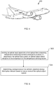
- FIG. 4 there is illustrated schematically a vehicle 400, in this example an aircraft 400, in which the electrical energy distribution network temperature monitoring apparatus described above with reference to any one of Figures 1 to 3 may be used, and/or a system comprising the electrical energy distribution network temperature monitoring apparatus and the electrical energy distribution network, described above with reference to any one of Figures 1 to 3 , may be used.
- the vehicle 400 is a transport vehicle 400.
- Figure 5 illustrates schematically a method of monitoring the temperature of a vehicle's electrical energy distribution network (for example the network described above with reference to any one of Figures 1 to 3 ).
- the method comprises sending an optical input signal into a first optical fibre, the first optical fibre comprising one or more temperature sensing sections, each temperature sensing section being in thermal contact with a portion of the vehicle's electrical energy distribution network, each temperature sensing section being arranged to produce, in response to the optical input signal, an optical output signal indicative of the temperature of the temperature sensing section.
- the first optical fibre may be that described above with reference to any one of Figures 1 to 3 .
- the method comprises determining a temperature of the vehicle's electrical energy distribution network based on one or more of the optical output signals. This may be achieved by any one or combination of the techniques, and/or may be implemented by any one or combination of the features of the apparatus, described above with reference to Figures 1 to 3 . In some examples, the method may comprise controlling the vehicle's electrical energy distribution network based on the determined temperature, for example as described above with reference to any one of Figures 1 to 3 .
Landscapes
- Physics & Mathematics (AREA)
- General Physics & Mathematics (AREA)
- Engineering & Computer Science (AREA)
- Power Engineering (AREA)
- Optics & Photonics (AREA)
- Aviation & Aerospace Engineering (AREA)
- Mechanical Engineering (AREA)
- Measuring Temperature Or Quantity Of Heat (AREA)
Description
- The present invention relates to a temperature monitoring apparatus, and more particularly to an apparatus configured to monitor a temperature a portion of a vehicle's electrical energy distribution network.
- Vehicles, such as aircraft, comprise electrical energy distribution networks, or electrical power distribution networks, to deliver electrical energy from electrical energy sources, such as batteries or generators, to electrical energy consumers, such as electrical equipment of the vehicle. Electrical energy distribution networks can generate a significant amount of heat.
- To reduce the risk of overheating, electrical energy distribution networks may be oversized, i.e. possess a power or current rating larger, in some cases much larger, than the actual power or current distributed through the network. However, this is costly and can add unnecessary mass to the electrical energy distribution network, which may be undesirable in vehicles such as aircraft.
- Typical temperature sensing systems used on vehicles such as aircraft are based on thermocouples and resistance temperature detector (RTD) devices. A thermocouple comprises two dissimilar electrical conductors that produces a temperature dependant voltage that can be measured to interpret temperature. An RTD device comprises a length of wire, for example of pure metal, that has a defined resistance to temperature relationship that can be used to provide an indication of temperature. However, applying such temperature sensing systems to electrical energy power distribution network may lead to a complex, inflexible and heavy system, which may be undesirable in vehicles such as aircraft. Further, such sensors (and/or their electrical wiring) would require a high level of protection or shielding in order to mitigate Electro Magnetic Interferences (EMI) from the electrical energy distribution network itself, or from lightning currents, which may be problematic in aircraft.
WO2008054429 discloses an optical fibre coupled system of laser-based sensors for measuring parameters associated with powered flight.WO011089244 WO2015199590 discloses an optical fibre sensor system arranged to detect a temperature change in a zone in an aircraft.US2014/0266742 discloses a thermal event detection and notification system comprising sensing means for detecting a thermal event and means for providing an indication of the location of the detected thermal event. - It is an object of the present invention to mitigate at least some of the drawbacks of the prior art.
- According to a first aspect of the present invention, there is provided a system comprising a temperature monitoring apparatus configured to monitor a temperature of a portion of a vehicle's electrical energy distribution network, the apparatus comprising: a first optical fibre, the first optical fibre comprising one or more temperature sensing sections, each temperature sensing section being in thermal contact with a portion of a vehicle's electrical energy distribution network, each temperature sensing section being arranged to produce, in response to an optical input signal, an optical output signal indicative of the temperature of the temperature sensing section; wherein the apparatus is arranged to determine a temperature of the portion of the vehicle's electrical energy distribution network based on one or more of the output optical signals in use; and the vehicle's electrical energy distribution network; wherein the electrical energy distribution network comprises a management unit (UG) arranged to control a flow of electrical energy within the electrical energy distribution network based on the determined temperature.
- Optionally, one or more of the temperature sensing sections is arranged for temperature dependant optical back-scattering of the optical input signal thereby to produce the optical output signal.
- Optionally, one or more of the temperature sensing sections comprises a Fibre Bragg Grating.
- Optionally, the first fibre comprises an optical absorber at or near a termination point of the first fibre.
- Optionally, the apparatus comprises a plurality of said first optical fibres, each first optical fibre being for thermal contact with a respective different portion of the electrical energy distribution network.
- Optionally, the apparatus comprises an optical director component arranged for directing the optical input signal to, and/or the output optical signal from, each of the plurality of first optical fibres.
- Optionally, the optical director component comprises a passive optical splitter arranged to direct the optical input signal to, and/or the optical output signal from, the plurality of first optical fibres.
- Optionally, the optical director component comprises an active optical switch controllable to direct the optical input signal to, and/or the optical output signal from, a selectable one or more of the first optical fibres.
- Optionally, the optical director component comprises a predetermined number of ports each for connection of a said first optical fibre.
- Optionally, the apparatus comprises a feeder optical fibre arranged to provide the optical input signal to, and/or the optical output signal from, the optical director component.
- Optionally, the apparatus comprises an optical interrogator arranged to provide the optical input signal to one or more of the temperature sensing sections of the or each first optical fibre.
- Optionally, the optical interrogator is arranged to receive the optical output signal from one or more of the temperature sensing sections of the or each first optical fibre.
- Optionally, the apparatus is arranged to provide the optical input signal to the or each of the first optical fibres simultaneously.
- Optionally, the apparatus is arranged to provide the optical input signal to the or each of the first optical fibres sequentially.
- Optionally, the electrical energy distribution network comprises a management unit arranged to control the flow of electrical energy within the electrical energy distribution network based on the determined temperature.
- Optionally, the electrical energy distribution network comprises one or more nodes and one or more links each connected to one or more of the nodes, wherein the or each first optical fibre is in thermal contact with a respective one of the links, and wherein the apparatus is arranged to determine the temperature of one or more of the links.
- Optionally, the or each first optical fibre is embedded in a respective one of the links.
- Optionally, one or more of the nodes are active nodes, and the management unit is arranged to control the one or more active nodes in order to control each of the electrical connections of the links connected to the or each active node.
- Optionally, the electrical energy distribution network comprises a plurality of the nodes and a plurality of internode links, the internode links connecting together the nodes to form at least one mesh of a meshed network, the or each mesh being polygonal of an order higher than or equal to three, at least one of the nodes of each mesh being an active node.
- Optionally, the management unit is arranged to control the one or more active nodes using optical control signals transmitted via one or more optical fibres of the temperature monitoring apparatus.
- According to a second aspect of the present invention, there is provided a vehicle comprising the system according to the first aspect.
- Optionally, the vehicle is an aircraft.
- According to a third aspect of the present invention, there is provided a method of monitoring the temperature of and controlling a flow of electrical energy within a vehicle's electrical energy distribution network, the method comprising: sending an optical input signal into a first optical fibre, the first optical fibre comprising one or more temperature sensing sections, each temperature sensing section being in thermal contact with a portion of the vehicle's electrical energy distribution network, each temperature sensing section being arranged to produce, in response to the optical input signal, an optical output signal indicative of the temperature of the temperature sensing section; determining a temperature of the vehicle's electrical energy distribution network based on one or more of the optical signals; and controlling, using a management unit of the electrical energy distribution network, a flow of electrical energy within the electrical energy distribution network based on the determined temperature.
-
-
Figure 1 illustrates schematically a vehicle electrical energy distribution network temperature monitoring apparatus, according to an example; -
Figure 2 illustrates schematically a vehicle electrical energy distribution network temperature monitoring apparatus, according to an example; -
Figure 3 illustrates schematically a vehicle electrical energy distribution network temperature monitoring apparatus, according to an example; -
Figure 4 illustrates schematically a vehicle in which the electrical energy distribution network temperature monitoring apparatus may be used, according to an example; and -
Figure 5 illustrates schematically a method according to an example. - Referring to
Figure 1 , there is illustrated atemperature monitoring apparatus 10. Thetemperature monitoring apparatus 10 is an electrical energy distribution networktemperature monitoring apparatus 10. Specifically, theapparatus 10 is a vehicle electrical energy distribution networktemperature monitoring apparatus 10. Thetemperature monitoring apparatus 10 is configured to monitor a temperature of a portion of a vehicle's electrical energy distribution network. For example, the vehicle may be a transport vehicle. For example, the vehicle may be an aircraft. - The
apparatus 10 comprises a firstoptical fibre 50. The firstoptical fibre 50 comprises one or more temperature sensing sections 48 (three are illustrated inFigure 1 ). Eachtemperature sensing section 48 is in thermal contact with aportion 60 of the vehicle's electrical energy distribution network (not shown inFigure 1 ). Eachtemperature sensing section 48 is arranged to produce, in response to an optical input signal, an optical output signal indicative of the temperature of thetemperature sensing section 48. Theapparatus 10 is arranged to determine a temperature of theportion 60 of the transport vehicle electrical energy distribution network (not shown inFigure 1 ) based on one or more of the optical output signals. - The
temperature monitoring apparatus 10 being based on optical fibres as described above allows for monitoring of the temperature of the vehicle's electrical energy distribution network by an apparatus that is relatively lightweight and has a relatively low susceptibility to Electro Magnetic Interferences (EMI) from the electrical energy distribution network itself, or from lightning currents, for example. Further, the optical fibre-basedapparatus 10 may be relatively flexible in its deployment, and may be relatively easily scalable to cover large, or a large number of, portions, for example power cables, of the vehicle's electrical energy distribution network. Monitoring the temperature of aportion 60 of the vehicle's electrical energy distribution network may allow for overheating of theportion 60 of the network to be determined and hence controlled and/or avoided. Accordingly, components of the vehicle's electrical energy distribution network may have reduced power or current ratings, as there is a reduced chance of overheating occurring, and hence the components of the electrical energy distribution network may be made smaller and/or lighter, which may be desirable for vehicles such as aircraft. - The
apparatus 10 comprises anoptical interrogator 56. Theoptical interrogator 56 is in optical communication with the firstoptical fibre 50. For example, thefirst fibre 50 may be connected to theoptical interrogator 56 via a suitable port (not shown). Theoptical interrogator 56 is arranged to provide the optical input signal to one or more of thetemperature sensing sections 48 of the firstoptical fibre 50. Theoptical interrogator 56 is arranged to receive the optical output signal from one or more of thetemperature sensing sections 48 of the or each firstoptical fibre 50. Theoptical interrogator 56 comprises a light source (not shown) for generating the optical input signal, and an optical detector (not shown) for detecting the output optical signal. In some examples, theoptical interrogator 56 is arranged to determine a temperature or temperature characteristic of theportion 60 of the vehicle's electrical energy distribution network (not shown inFigure 1 ) based on the detected optical output signals. For example, theoptical interrogator 56 may comprise a processor and a memory (not shown) arranged to process the detected output optical signals and determine on the basis of these, by suitable calibration, one or more temperatures associated with one or more of thetemperature sensing sections 48 respectively. In other examples, this determination may be performed by another or other components (not shown) of theapparatus 10. - A change in the temperature of a
temperature sensing portion 48 may cause a change in a scattering characteristic of thetemperature sensing section 48, which may cause a change in the optical output signal produced by thetemperature sensing section 48 in response to an optical input signal. That is, the optical input signal may experience temperature dependant scattering at atemperature sensing section 48, which scattered light may form the optical output signal. - In some examples, one or more of the
temperature sensing sections 48 is arranged for temperature dependant optical back-scattering of the optical input signal thereby to produce the optical output signal. That is, the optical input signal may travel in a first direction along the firstoptical fibre 50, and the optical input signal may experience temperature dependant scattering at atemperature sensing section 48, and the scattered light forming the optical output signal may travel in a second direction along the firstoptical fibre 50, opposite to the first direction. This may allow a reduction in the length of the firstoptical fibre 50 needed to determine the temperature of theportion 60 of the electrical energy distribution network (not shown). - In some examples, as illustrated in
Figure 1 , the firstoptical fibre 50 may comprise a plurality of thetemperature sensing sections 48. In some examples, thetemperature sensing sections 48 may be equally spaced along a firstoptical fibre 50. Having a plurality oftemperature sensing sections 48, for example along the length of a single optical fibre, may allow for temperature monitoring along a length of the power cable orelectrical link 60 of the electrical energy distribution network, and which is sensitive to local variations in temperature along the length of theelectrical link 60. This may provide for a more accurate and/or more comprehensive temperature determination, and hence for improved detection and/or avoidance of overheating of distribution network, for example. - In some examples, one or more of the
temperature sensing sections 48 comprises a Fibre Bragg Grating (FBG). A FBG is a distributed Bragg reflector located within theoptical fibre 50 and comprising periodic variations in the refractive index of the core of thefibre 50 along a section of the length of theoptical fibre 50. The wavelength of a band of light reflected from the FBG is dependent on temperature of thesection 48. When an FBG is in thermal contact with (for example bonded to, attached to, tightly wound around, or embedded in) a portion (for example a cable or other electrical link 60) of the electrical energy distribution network, a change in temperature of theportion 60 changes a temperature of the FBG, which in turn changes the wavelength of a band of light reflectable by the FBG. Therefore, by monitoring light reflected (forming the output optical signal) from an FBG in thermal contact with theportion 60, the temperature of theportion 60 may be determined. - A plurality of the
temperature sensing sections 48 of a single firstoptical fibre 50 may each comprise an FBG. For example, the range of wavelengths reflectable by one FBG located in a fibre may be different from the range of wavelength reflectable by a second FBG in the same fibre. A first FBG may therefore be transparent to a range of wavelengths needed to interrogate a second FBG, and the first and second FBGs may be transparent to a range of wavelengths needed to interrogate a third FBG, and so on. As a result, multipletemperature sensing sections 48 may be located in a singleoptical fibre 50, which may reduce the weight and complexity of connections needed to interrogate thetemperature sensing sections 48. The identity and hence location of a particular one of the FBGs interrogated may be determined based on the range of input optical signal wavelengths used for interrogation and/or the range of wavelengths of the output optical signal received. - In some examples, one or more of the
temperature sensing sections 48 are arranged for Brillouin scattering and/or Raman scattering or the like. In these examples, the firstoptical fibre 50 may be an optical fibre, for example a telecommunicationsoptical fibre 50. In these examples, the firstoptical fibre 50 itself, or a portion thereof, may constitute atemperature sensing section 48. In Brillouin scattering examples, the optical input interacts with material deformation waves, for example phonons, in theoptical fibre 50, the properties of which phonons may vary with temperature. A light wave of the optical input signal interacts with a deformation wave of theoptical fibre 50 to produce a scattered light wave, which may have a different frequency to the optical input signal. The scattered light wave may then be used as the temperature dependant optical output signal. For example, the frequency shifts as a result of Brillouin scattering as compared to the frequency of the input optical signal may be detected with an interferometer. In Raman scattering, the optical input signal is scattered by excitation of vibrational and rotational transitions of molecules of theoptical fibre 50, the properties of which scattered light may vary with temperature of theoptical fibre 50. The scattered light may then be used as the temperature dependant optical output signal. For example, the optical output signal produced as a result of Raman scattering as compared to the input optical signal may be detected with an interferometer or a grating spectrometer, for example. - For both the Brillouin and Raman scattering examples (and other scattering examples), the temperature of a particular location along the
optical fibre 50 may be determined based on time-of-flight techniques. For example, theinterrogator 56 may measure the time between sending of the optical input signal and receipt of the optical output signal and use this time in conjunction with the speed of light in theoptical fibre 50 to determine the distance along theoptical fibre 50 at which the optical output signal was produced. - In some examples, the first
optical fibre 50 may comprise anoptical absorber 52 at or near an end or termination point of the firstoptical fibre 50. For example, theoptical absorber 52 may be at a termination point of the firstoptical fibre 50 that is distal to theoptical interrogator 56. Theoptical absorber 52 may avoid or reduce back-reflections of the optical input signal, and hence may improve the sensitivity of the detection of the optical output signal produced by thetemperature sensing portions 48. - Referring now to
Figure 2 , in some examples, the apparatus (givenreference sign 20 inFigure 2 ) may comprise a plurality of the firstoptical fibres Figure 2 ), each firstoptical fibre different portion optical fibres Figure 1 . - The electrical energy distribution network may comprise one or more nodes n1 and one or
more links links optical fibre links apparatus 20 is arranged to determine the temperature of one or more of thelinks link 60, also referred to herein as anexternal link 60. Thefirst portion 61 of the distribution network is afirst link 62 extending from the electrical node n1, and thesecond portion 62 of the distribution network is a second,separate link 62 extending from the electrical node n1. The node n1 distributes electrical energy from the source S to thefirst link 61 and thesecond link 62, from where electrical energy may be provided to one or more electrical consumers (not shown inFigure 2 ). One of the firstoptical fibres 50a is in thermal contact with thefirst link 61, and another of the firstoptical fibres 50b is in thermal contact with thesecond link 62. Having a plurality of first optical fibres may allow for the temperature of a wider range of the vehicle's electrical energy distribution network to be monitored. - In the example of
Figure 2 , theapparatus 20 comprises an optical director component d1 arranged for directing the optical input signal to, and/or the optical output signal from, each of the plurality of firstoptical fibres optical fibre 54 is arranged to provide the optical input signal to, and/or the optical output signal from, the optical director component n1 (and hence the optical input signal to, and/or the optical output signal from, the one or more of thefirst fibres optical fibre 54 optically connects the optical interrogator 56 (which may be the same or similar to that described above with reference toFigure 1 ) with the director component d1. The optical director component d1 may be located at or near the node n1. In some examples, the optical director component d1 may be integral with the node n1. This may help to save space and weight. The optical director component d1 may allow for the temperature of multiple portions of the electrical energy distribution network to be monitored with a relatively small length of fibre optic cable. This may save weight and expense of thetemperature monitoring apparatus 20. - In some examples, the
apparatus 20 may be arranged to provide the optical input signal to the or each of the firstoptical fibre optical fibres optical fibre 54 and split it equally between each of the firstoptical fibres optical fibres apparatus 20, for example theoptical interrogator 56, to determine the temperature of both thefirst link 61 and thesecond link 62 of the vehicle's energy distribution network substantially simultaneously. This may allow a relatively fast temperature determination over different portions of the distribution network, and hence may allow for faster, for example real time or near real time, response to overheating of the distribution network, for example. The passive optical splitter may provide for relatively inexpensive and simple means by which to distribute the optical interrogation over multiplefirst fibres - In some examples, the light source (not shown) of the
optical interrogator 56 may comprise a broadband light source, and the optical input signal may be a broad band spectrum of light. The optical detector (not shown) of theoptical interrogator 56 may comprise a wavelength meter arranged to measure wavelength of the optical output signals. Theinterrogator 56 may be arranged to determine from which firstoptical fibre temperature sensing section 48 of a first one 50a of the firstoptical fibres temperature sensing section 48 of a second one 50b of the firstoptical fibres optical interrogator 56 may comprise a tuneable narrow band optical source, for example a tuneable laser, which may be controllable to emit light successively at different wavelengths. Theinterrogator 56 may be arranged to determine from which firstoptical fibre temperature sensing section 48 of a first one 50a of the firstoptical fibres temperature sensing section 48 of a second one 50b of the firstoptical fibres optical interrogator 56 may be arranged to measure the time between sending of the optical input signal and receipt of the optical output signal and use this time in conjunction with the speed of light to determine by which firstoptical fibre temperature sensing section 48 of a first one 50a of the firstoptical fibres temperature sensing section 48 of a second one 50b of the firstoptical fibres - In some examples, the
apparatus 20 may be arranged to provide the optical input signal to the or each of the firstoptical fibres optical fibres optical interrogator 56 to direct light between theoptical interrogator 56 and a first 50a of the firstoptical fibres optical interrogator 56 and a second 50b of the firstoptical fibres optical interrogator 56 and the second 50b of the firstoptical fibres optical interrogator 56 and the first 50a of the firstoptical fibres optical interrogator 56 using optical communication via the feederoptical fibre 54. For example, the active optical switch may be arranged to process optical control signals received from theoptical interrogator 56 via the feederoptical fibre 54, and to select, on the basis thereof, which of the firstoptical fibres optical interrogator 56 may determine from which of the firstoptical fibres optical fibres optical interrogator 56 which of the firstoptical fibres optical interrogator 56. The active optical switch may also provide for flexibility and scalability of thetemperature monitoring system 20. - In some examples, the optical director component d1, or each of the optical director components d1 (described in more detail below), may comprise (e.g. have) a predetermined number of ports each for connection of a first
optical fibre optical fibre optical fibre 54. Having multiple ports (e.g. more ports than would be necessary for a give deployment) allows for the temperature monitoring system to be adapted and/or scaled without having to replace the optical director component d1. Each optical director component d1 having (the same) predetermined number of ports and/or being the same as one another allows the adaptability and/or scalability without increasing the part number count. This may be important for aircraft and may increase the efficiency of and/or reduce the cost of manufacture and/or maintenance of the aircraft, for example. - In some examples, the
first fibre link first fibre links optical fibre 50 by the rest of the power cable, from damage. This may also allow for improved mechanical isolation of the firstoptical fibres 50 which may allow for improved accuracy of the temperature measurements. - As illustrated in
Figure 2 , the vehicle's electrical energy distribution network may comprise a management unit UG arranged to control the flow of electrical energy within the vehicle's electrical energy distribution network. The management unit UG may be arranged to control the flow of electrical energy within the electrical energy distribution network based on the determined temperature. For example, the management unit UG may be in communication with theoptical interrogator 56, for example over asuitable data link 57. Theoptical interrogator 56 may provide information to the management unit UG. For example, theoptical interrogator 56 may provide the temperature or a temperature characteristic of one or more or all of thelinks links - In some examples, one or more of the nodes n1 of the distribution network are active nodes. For example, an active node may be controllable to control the flow of electrical energy to one or more of the
links links links link link suitable data link 59. In one example, thedata link 59 may be in the form of anoptical fibre 59, which may be separate to the feederoptical fibre 54. - In some examples, the management unit UG is arranged to control the one or more active nodes using optical control signals transmitted via one or more
optical fibres 54 of thetemperature monitoring apparatus 20. For example, the management unit UG may pass a control signal to theoptical interrogator 56 via thedata link 57. Theoptical interrogator 56 may inject the control signal as an optical control signal into the feederoptical fibre 54. The active node n1 may be arranged to receive and process the optical control signal. For example, an optical splitter (not shown) may be used to divert a portion of light input into the feederoptical fibre 54 to a processor (not shown) of the active node n1. For example, the active node n1 and the optical director component d1 may be substantially integral with one another and/or provided in a common housing (not shown). The processor (not shown) of the active node n1 may then process the optical control signal and convert it into an electrical control signal so as to control the active node n1 according to the optical control signal. In some examples, the optical control signal may be provided in a different band of wavelengths to the optical input signal used for temperature monitoring. This may reduce the risk of an input optical signal being misinterpreted by the active node n1 as an optical control signal. Providing the control signals for the active node n1 and the optical input signal for the temperature monitoring in a commonoptical fibre 54 may allow for a cost, weight and/or complexity reduction as compared to providing different channels for each. - In some examples, if one of the power cables or
links optical fibre 50, theoptical interrogator 56 may determine that this has occurred, and this may be provided to the management unit UG as an indication for the health status of the power cable. For example, if, despite sending an optical input signal expected to lead to an optical output signal being received, theoptical interrogator 56 does not receive the expected optical output signal, theoptical interrogator 56 may determine that there may be a fault with the power cable of link, for example that a BITE (Built-in Test Equipment) event has occurred. The management unit UG may then control the flow of electrical energy in the distribution network accordingly, for example so as to avoid the possible damage location, and/or may raise an alarm as appropriate. - In some examples, as is now described with reference to
Figure 3 , the electrical energy distribution network comprises a plurality of the nodes n1 - n8 and a plurality of internode links 11- 19, 110, the internode links 11- 19, 110 connecting together the nodes n1-n8 to form at least one mesh M1-M3 of a meshed network, the or each mesh M1 - M3 being polygonal of an order higher than or equal to three. - For example, the electrical energy distribution network may be the same or similar to that described in
US2015134137 , the entire contents of which is incorporated by reference. - Referring again to
Figure 3 , power supply sources S1, S2 and equipment C1 - C3 to be supplied by said power supply sources S1, S2 are connected to the mesh network by means ofexternal links external links - Because in a polygonal mesh of order higher than or equal to three, to go from one node to another, three paths are possible, the electrical energy distribution network can be configured by controlling at least one active node by means of the management unit UG. This configuration can be effected during malfunctioning, for example.
- In this example, the vehicle's electrical energy distribution network temperature monitoring apparatus (given
reference numeral 30 inFigure 3 ) comprises a plurality of optical director components d1, d3, d5, d6, d8, each associated with a respective one of the active nodes n1, n3, n5, n6, n8. Each director component may be the same or similar as that described above with reference toFigure 2 . Each optical director component d1, d3, d5, d6, d8 is in optical communication with theoptical interrogator 56 via a respective feederoptical fibre 54. Theoptical interrogator 56 may be the same or similar to that described above with reference toFigures 1 and 2 . Each director component d1, d3, d5, d6, d8 is connected to a plurality of firstoptical fibres 50. One or more or each of the plurality of firstoptical fibres 50 may be the same or similar to that described above with reference toFigures 1 and 2 . Each of the plurality of firstoptical fibres 50 connected to a given director component d1, d3, d5, d6, d8 is in thermal contact with a respective one of the plurality of links connected to the active node n1, n3, n5, n6, n8 associated with the given director component d1, d3, d5, d6, d8. According to this scheme, each link of the network (external links and internode links) may have an associated first optical fibre to monitor the temperature thereof. Hence the temperature along all or substantially all of the links of the network may be monitored. Theapparatus 30 may therefore determine whether any of the links of the network are overheating. Further, as mentioned above, in some examples the temperature can be determined at multiple locations along a firstoptical fibre 50. Hence theapparatus 30 may determine whether any portion of any of the links of the network are overheating. This may allow for a more comprehensive monitoring of the temperature of the power network, for example as compared to monitoring temperatures at the nodes alone. - Similarly to as described above with reference to
Figure 2 , theoptical interrogator 56 may interrogate each of the firstoptical fibres 50 simultaneously or sequentially. For example, theoptical interrogator 56 may introduce an optical input signal into each of the feederoptical fibres 54, and similarly to as described above with reference toFigures 1 and 2 , may identify the firstoptical fibre 50 ortemperature sensing sections 48 of the firstoptical fibre 50 from which a given optical output signal is received based on wavelength or time or phase division multiplexing as described above, for example in combination with the identity of the feederoptical fibre 54 via which the given optical output signal is received. - The
optical interrogator 56 may determine the temperature of, or the temperature of a portion of, each link of the network. Theoptical interrogator 56 may provide this temperature information to the management unit UG by asuitable data link 57. This information may be provided, for example, at a rate of 10Hz, for example. Based on this information, the management unit UG may determine that one or more of the links is or may be overheating or may be malfunctioning in another way. The management unit UG may then control one or more of the active nodes n1, n3, n5, n6, n8 (control for example as described above with reference toFigure 2 ) so as to reconfigure the network so as to reduce or prevent electrical energy flowing in the link determined to be overheating or otherwise malfunctioning. This may prevent or avoid or reduce the overheating in the link. Because each mesh M1-M3 is a polygonal mesh of order higher than or equal to three, regardless of which of links is malfunctioning, electrical energy may nonetheless be routed from one node to another node of the network. - As a specific example, in an initial configuration, the source S2 provides electrical energy to the consumer C1 via
external link 115, active node n6,internode link 13, active node n1, andexternal link 111. At some point, the temperature of a portion of theinternode link 13 between active node n6 and the active node n1 may increase, for example due to an increase in current flowing throughinternode link 13, for example due to a fault. This may accordingly increase the temperature of atemperature sensing section 48 of the firstoptical fibre 50 in thermal contact with theinternode link 13. This increase in temperature may be determined by theinterrogator 56 based on a change in the optical output signal produced by thetemperature sensing section 48 of the firstoptical fibre 50 in response to an optical input signal. Theinterrogator 56 may pass this information to the management unit UG. The management unit UG may determine that the temperature of theinternode link 13 is to be reduced, for example because it is or may be overheating. The management unit UG may then control the active node n6 and/or active node n1 to reduce or prevent the flow of electrical energy throughinternode link 13. The management unit UG may also control the active node n6 and/or active node n1 to increase or allow the flow of electrical energy throughinternode links 12 and 11 via passive internode link n2. The active node n1 may therefore continue to provide electrical energy to the consumer C1, whilst the temperature of theinternode link 13 may be allowed to reduce. - As another example, one of the sources S1 (or S2) may, due to a failure or fault, inject an abnormal level of electrical power into the electrical energy distribution network, which may cause the temperature of the
external link 112 connected the source S1 (or in the case of fault of the source S2, the temperature of theexternal link 115 connected to source S2) to change, for example increase, which may accordingly change the temperature of atemperature sensing section 48 of the firstoptical fibre 50 in thermal contact with the external link 112 (or in the case of a fault of the source S2, the temperature of atemperature sensing section 48 of the firstoptical fibre 50 in thermal contact with the external link 115), which may in turn be detected by theinterrogator 56 as described above. Theinterrogator 56 may pass this information to the management unit UG. The management unit UG may determine that the temperature of the external link 112 (or external link 115) is to be reduced, for example because it is or may be overheating. The management unit UG may then control the source S1 (or S2) to shut down, or for example may launch a warning or alert for a system (not shown) controlling the operation of the source S1 (or S2) to cause the source S1 (or S2) to shut down. In some examples (not shown), one or more of the sources S1, S2 and/or one or more of the consumers C1, C2, C3 may alternatively or additionally each have an integrated protection mechanism (not shown) to detect whether there is a fault in the source S1, S2 or consumer C1, C2, C3 itself and/or whether there is a fault in the electrical energy supplied by and/or supplied to the source S1, S2 or the consumer C1, C2, C3. In these examples, the or each integrated protection mechanism may pass fault or other information to the management unit UG, and the management unit UG may control the electrical energy distribution network and/or systems (not shown) controlling the operation of the sources S1, S2 or consumers C1, C2, C3, based at least in part on this information. - The system of the
temperature monitoring apparatus 30 and the vehicle's electrical energy distribution network may prevent or control overheating of a portion of the network, for example whilst allowing the network to continue to deliver electrical energy. Accordingly, components of the electrical energy distribution network may have reduced power or current ratings, as there is a reduced chance of overheating occurring, and hence the components of the electrical energy distribution network may be made smaller and/or lighter, which may be desirable for vehicles such as aircraft. - In some examples, the
temperature monitoring apparatus 30 is arranged to monitor the temperature of substantially an entire length of one or more electrical flow paths in the distribution network. This may allow the management unit UG to determine the most efficient or safest electrical flow path through the distribution network. For example, if the temperature of one or more links, or an average temperature of all the links, of a first flow path from a given source S1, S2 to a given consumer C1, C2, C3 is higher than the temperature of one or more links, or an average temperature of all the links, of a second flow path from the given source S1, S2 to the given consumer C1, C2, C3, then the management unit UG may determine that it would be safer and/or more efficient (e.g. due to lower resistance) to configure the distribution network according to the second flow path, and hence may control the one or more active nodes n1, n3, n5, n6, n8 of the network to implement the second flow path accordingly. This may therefore allow for safer and/or more efficient electrical energy distribution. The temperature information provided by theapparatus 30 may therefore allow the management unit UG to effect dynamic and intelligent distribution network control. - The temperature sensing components of the
apparatus 30 being optical (and in examples where the optical director competent d1 is a splitter, then the optical director component being optical) allows for a greatly reduced or eliminated susceptibility to EMI, and a greatly reduced need to provide lightning protection, as compared to the use of electrical temperature sensors. Thetemperature sensing sections 48 and the optical interrogator may be galvanically isolated for example by use of dielectric optical fibres. Further, the temperature monitoring being based on optical fibres may greatly reduce the weight compared to the use of electrical temperature sensors. This may be particularly important for transport vehicles, such as aircraft. - Referring to
Figure 4 , there is illustrated schematically avehicle 400, in this example anaircraft 400, in which the electrical energy distribution network temperature monitoring apparatus described above with reference to any one ofFigures 1 to 3 may be used, and/or a system comprising the electrical energy distribution network temperature monitoring apparatus and the electrical energy distribution network, described above with reference to any one ofFigures 1 to 3 , may be used. In this example, thevehicle 400 is atransport vehicle 400. -
Figure 5 illustrates schematically a method of monitoring the temperature of a vehicle's electrical energy distribution network (for example the network described above with reference to any one ofFigures 1 to 3 ). - In
step 502, the method comprises sending an optical input signal into a first optical fibre, the first optical fibre comprising one or more temperature sensing sections, each temperature sensing section being in thermal contact with a portion of the vehicle's electrical energy distribution network, each temperature sensing section being arranged to produce, in response to the optical input signal, an optical output signal indicative of the temperature of the temperature sensing section. The first optical fibre may be that described above with reference to any one ofFigures 1 to 3 . - In
step 504, the method comprises determining a temperature of the vehicle's electrical energy distribution network based on one or more of the optical output signals. This may be achieved by any one or combination of the techniques, and/or may be implemented by any one or combination of the features of the apparatus, described above with reference toFigures 1 to 3 . In some examples, the method may comprise controlling the vehicle's electrical energy distribution network based on the determined temperature, for example as described above with reference to any one ofFigures 1 to 3 . - It is noted that the term "or" as used herein is to be interpreted to mean "and/or", unless expressly stated otherwise.
Claims (15)
- A system comprising:a temperature monitoring apparatus (10, 20, 30) configured to monitor a temperature of a portion of a vehicle's electrical energy distribution network, the apparatus comprising:a first optical fibre (50, 50a, 50b), the first optical fibre comprising one or more temperature sensing sections (48), each temperature sensing section being in thermal contact with a portion (60, 61, 62) of the vehicle's electrical energy distribution network, each temperature sensing section (48) being arranged to produce, in response to an optical input signal, an optical output signal indicative of the temperature of the temperature sensing section (48);wherein the apparatus (10, 20, 30) is arranged to determine a temperature of the portion (60, 61, 62) of the vehicle's electrical energy distribution network based on one or more of the output optical signals in use; andthe vehicle's electrical energy distribution network; characterized in that the electrical energy distribution network comprises a management unit (UG) arranged to control a flow of electrical energy within the electrical energy distribution network based on the determined temperature.
- The system according to claim 1, wherein one or more of the temperature sensing sections (48) is arranged for temperature dependant optical back-scattering of the optical input signal thereby to produce the optical output signal; and/or
wherein one or more of the temperature sensing sections (48) comprises a Fibre Bragg Grating; and/or
wherein the first fibre (50, 50a, 50b) comprises an optical absorber (52) at or near a termination point of the first fibre. - The system according to claim 1 or claim 2, wherein the apparatus (10, 20, 30) comprises a plurality of said first optical fibres (50, 50a, 50b), each first optical fibre (50, 50a, 50b) being in thermal contact with a respective different portion of the electrical energy distribution network.
- The system according to claim 3, wherein the apparatus (10, 20, 30) comprises an optical director component (d1) arranged for directing the optical input signal to, and/or the output optical signal from, each of the plurality of first optical fibres (50, 50a, 50b).
- The system according to claim 4, wherein the optical director component (d1) comprises a passive optical splitter arranged to direct the optical input signal to, and/or the optical output signal from, the plurality of first optical fibres (50, 50a, 50b); or wherein the optical director component (d1) comprises an active optical switch controllable to direct the optical input signal to, and/or the optical output signal from, a selectable one or more of the first optical fibres (50, 50a, 50b); and/or
wherein the optical director component (d1) comprises a predetermined number of ports each for connection of a said first optical fibre. - The system according to claim 4 or claim 5, wherein the apparatus (10, 20, 30) comprises a feeder optical fibre (54) arranged to provide the optical input signal to, and/or the optical output signal from, the optical director component (d1).
- The system according to any one of claim 1 to claim 6, wherein the apparatus (10, 20, 30) comprises an optical interrogator (56) arranged to provide the optical input signal to one or more of the temperature sensing sections (48) of the or each first optical fibre (50, 50a, 50b).
- The system according to claim 7, wherein the optical interrogator (56) is arranged to receive the optical output signal from one or more of the temperature sensing sections (48) of the or each first optical fibre (50, 50a, 50b).
- The system according to any one of claim 1 to claim 8, wherein the apparatus (10, 20, 30) is arranged to provide the optical input signal to the or each of the first optical fibres (50, 50a, 50b) simultaneously; and/or
wherein the apparatus (10, 20, 30) is arranged to provide the optical input signal to the or each of the first optical fibres (50a, 50b, 50c) sequentially. - The system according to claim any one of claim 1 to claim 9,
wherein the electrical energy distribution network comprises one or more nodes (n1) and one or more links (61, 62) each connected to one or more of the nodes (n1), wherein the or each first optical fibre (50, 50a, 50b) is in thermal contact with a respective one of the links (61, 62), and wherein the apparatus (10, 20, 30) is arranged to determine the temperature of one or more of the links (61, 62). - The system according to claim 10, wherein one or more of the nodes (n1) are active nodes, wherein the management unit (UG) is arranged to control the one or more active nodes (n1) in order to control each of the electrical connections of the links (61, 62) connected to the or each active node (n1).
- The system according to claim 11, wherein the electrical energy distribution network comprises a plurality of the nodes (n1) and a plurality of internode links (61, 62), the internode links connecting together the nodes (n1) to form at least one mesh of a meshed network, the or each mesh being polygonal of an order higher than or equal to three, at least one of the nodes (n1) of each mesh being an active node; and/or
wherein the management unit (UG) is arranged to control the one or more active nodes (n1) using optical control signals transmitted via one or more optical fibres of the temperature monitoring apparatus (10, 20, 30). - A vehicle (400) comprising the system according to any one of claim 1 to claim 12.
- The vehicle (400) according to claim 13, wherein the vehicle is an aircraft (400).
- A method of monitoring the temperature of and controlling a flow of electrical energy within a vehicle's electrical energy distribution network according to claims 13-14, the method comprising:sending an optical input signal into a first optical fibre (50, 50a, 50b), the first optical fibre comprising one or more temperature sensing sections (48), each temperature sensing section (48) being in thermal contact with a portion (60, 61, 62) of the vehicle's electrical energy distribution network, each temperature sensing section (48) being arranged to produce, in response to the optical input signal, an optical output signal indicative of the temperature of the temperature sensing section (48);determining a temperature of the vehicle's electrical energy distribution network based on one or more of the optical signals; andcontrolling, using a management unit (UG) of the electrical energy distribution network, a flow of electrical energy within the electrical energy distribution network based on the determined temperature.
Applications Claiming Priority (1)
| Application Number | Priority Date | Filing Date | Title |
|---|---|---|---|
| GB1802341.6A GB2570940A (en) | 2018-02-13 | 2018-02-13 | Temperature monitoring apparatus |
Publications (2)
| Publication Number | Publication Date |
|---|---|
| EP3524950A1 EP3524950A1 (en) | 2019-08-14 |
| EP3524950B1 true EP3524950B1 (en) | 2021-05-05 |
Family
ID=61731153
Family Applications (1)
| Application Number | Title | Priority Date | Filing Date |
|---|---|---|---|
| EP19156752.8A Active EP3524950B1 (en) | 2018-02-13 | 2019-02-12 | Temperature monitoring apparatus |
Country Status (3)
| Country | Link |
|---|---|
| US (1) | US11467043B2 (en) |
| EP (1) | EP3524950B1 (en) |
| GB (1) | GB2570940A (en) |
Cited By (1)
| Publication number | Priority date | Publication date | Assignee | Title |
|---|---|---|---|---|
| EP4560941A1 (en) | 2023-11-27 | 2025-05-28 | Airbus Defence and Space GmbH | Photonic transceiver module, periphery device, communication system and apparatus comprising same |
Families Citing this family (2)
| Publication number | Priority date | Publication date | Assignee | Title |
|---|---|---|---|---|
| GB2606337A (en) * | 2021-03-26 | 2022-11-09 | Airbus Sas | apparatus and method for detecting current imbalance |
| US12493085B2 (en) * | 2022-08-31 | 2025-12-09 | Ubicquia, Inc. | Apparatus, system, and method for detecting optical events associated with distribution transformers |
Citations (1)
| Publication number | Priority date | Publication date | Assignee | Title |
|---|---|---|---|---|
| US20140266742A1 (en) * | 2013-03-14 | 2014-09-18 | Kidde Technologies, Inc. | Thermal event detection and notification system |
Family Cites Families (17)
| Publication number | Priority date | Publication date | Assignee | Title |
|---|---|---|---|---|
| US4298794A (en) * | 1979-08-30 | 1981-11-03 | United Technologies Corporation | Fiber optic hot spot detector |
| GB9908075D0 (en) * | 1999-04-09 | 1999-06-02 | Secr Defence | An optical fibre sensor assembly |
| DE10111640A1 (en) * | 2001-03-10 | 2002-10-02 | Airbus Gmbh | Procedure for the detection and reporting of overheating and fires in an aircraft |
| US6776522B2 (en) * | 2002-10-09 | 2004-08-17 | Steven J. Syracuse | Apparatus and system for monitoring temperature of high voltage conductors |
| WO2008054429A2 (en) * | 2005-11-15 | 2008-05-08 | Zolo Technologies, Inc. | All-fiber architecture for an embedded flight sensor for aeropropulsion applications |
| EP2017593B1 (en) * | 2007-07-20 | 2013-09-04 | LIOS Technology GmbH | Method and system for determining a physical property as a function of position |
| US8130101B2 (en) * | 2009-03-23 | 2012-03-06 | Lockheed Martin Corporation | Embedded power cable sensor array |
| DE102010001197B4 (en) * | 2010-01-25 | 2019-05-29 | Draka Cable Wuppertal Gmbh | Sensor element and method for its production and use |
| US9088149B2 (en) * | 2012-03-27 | 2015-07-21 | The Boeing Company | Methods and apparatus to detect and control plasma fires |
| US9209494B2 (en) * | 2012-09-28 | 2015-12-08 | Palo Alto Research Center Incorporated | Monitoring/managing electrochemical energy device using detected intercalation stage changes |
| FR3013163B1 (en) * | 2013-11-08 | 2018-09-14 | Airbus Operations | ELECTRIC POWER DISTRIBUTION NETWORK OF A TRANSPORT VEHICLE, SUCH AS AN AIRCRAFT, AND AN ELECTRICAL PLANT OF AN AIRCRAFT |
| EP3066424A1 (en) * | 2013-12-11 | 2016-09-14 | Moog Inc. | Fiber optic sensing and control system |
| US9583796B2 (en) * | 2014-04-01 | 2017-02-28 | Palo Alto Research Center Incorporated | Method for monitoring/managing electrochemical energy device by detecting intercalation stage changes |
| US10260964B2 (en) * | 2014-06-25 | 2019-04-16 | Saab Ab | Optical fiber sensor system for detecting temperature changes in an aircraft |
| GB201601060D0 (en) * | 2016-01-20 | 2016-03-02 | Fotech Solutions Ltd | Distributed optical fibre sensors |
| CA2967988C (en) * | 2016-05-19 | 2024-01-09 | Kidde Technologies, Inc. | Optical health monitoring for aircraft overheat and fire detection systems |
| US20190011491A1 (en) * | 2017-07-06 | 2019-01-10 | Palo Alto Research Center Incorporated | Optical monitoring for power grid systems |
-
2018
- 2018-02-13 GB GB1802341.6A patent/GB2570940A/en not_active Withdrawn
-
2019
- 2019-02-12 EP EP19156752.8A patent/EP3524950B1/en active Active
- 2019-02-12 US US16/273,796 patent/US11467043B2/en active Active
Patent Citations (1)
| Publication number | Priority date | Publication date | Assignee | Title |
|---|---|---|---|---|
| US20140266742A1 (en) * | 2013-03-14 | 2014-09-18 | Kidde Technologies, Inc. | Thermal event detection and notification system |
Cited By (1)
| Publication number | Priority date | Publication date | Assignee | Title |
|---|---|---|---|---|
| EP4560941A1 (en) | 2023-11-27 | 2025-05-28 | Airbus Defence and Space GmbH | Photonic transceiver module, periphery device, communication system and apparatus comprising same |
Also Published As
| Publication number | Publication date |
|---|---|
| GB201802341D0 (en) | 2018-03-28 |
| US11467043B2 (en) | 2022-10-11 |
| US20190250048A1 (en) | 2019-08-15 |
| GB2570940A (en) | 2019-08-14 |
| EP3524950A1 (en) | 2019-08-14 |
Similar Documents
| Publication | Publication Date | Title |
|---|---|---|
| US10112726B2 (en) | Optical health monitoring for aircraft overheat and fire detection systems | |
| US10436652B2 (en) | Optical health monitoring for aircraft overheat and fire detection systems | |
| US10585006B2 (en) | Aircraft overheat detection using optical fiber technology for system health monitoring by determining a physical characteristic associated with a location | |
| CN104185779B (en) | Temperature sensor optical fiber and electric device monitoring system | |
| US10488273B2 (en) | Measuring arrangement and temperature-measuring method, and sensor cable for such a measuring arrangement | |
| US6559437B1 (en) | Fiber optic damage sensor for wire and cable | |
| US11467043B2 (en) | Temperature monitoring apparatus | |
| EP2643663B1 (en) | Long fibre optic sensor system in a wind turbine component | |
| US20170334575A1 (en) | Optical health monitoring for aircraft overheat and fire detection | |
| EP2223052B1 (en) | Method and system for fiber-optic monitoring of spatially distributed components | |
| EP3770568B1 (en) | Integrated landing gear fire detection and fatigue monitoring system | |
| EP2824463A1 (en) | Optical fiber for sensor and power device monitoring system | |
| CN102103173A (en) | Method and system for monitoring current-carrying capacity of cable based on distributed optical fiber temperature measuring method | |
| EP3291192A1 (en) | Monitoring system of an aircraft bleed air system | |
| CA2998149C (en) | Modular sensing fiber optic cables | |
| US11788899B2 (en) | Apparatus and method for detection current imbalance | |
| CN112033574A (en) | Distributed fiber laser monitoring system and monitoring method | |
| CA2967981A1 (en) | Optical health monitoring for aircraft overheat and fire detection | |
| Wei et al. | Online monitoring system for motor vibration using fiber Bragg grating sensing technology |
Legal Events
| Date | Code | Title | Description |
|---|---|---|---|
| PUAI | Public reference made under article 153(3) epc to a published international application that has entered the european phase |
Free format text: ORIGINAL CODE: 0009012 |
|
| STAA | Information on the status of an ep patent application or granted ep patent |
Free format text: STATUS: THE APPLICATION HAS BEEN PUBLISHED |
|
| AK | Designated contracting states |
Kind code of ref document: A1 Designated state(s): AL AT BE BG CH CY CZ DE DK EE ES FI FR GB GR HR HU IE IS IT LI LT LU LV MC MK MT NL NO PL PT RO RS SE SI SK SM TR |
|
| AX | Request for extension of the european patent |
Extension state: BA ME |
|
| STAA | Information on the status of an ep patent application or granted ep patent |
Free format text: STATUS: REQUEST FOR EXAMINATION WAS MADE |
|
| 17P | Request for examination filed |
Effective date: 20200214 |
|
| RBV | Designated contracting states (corrected) |
Designated state(s): AL AT BE BG CH CY CZ DE DK EE ES FI FR GB GR HR HU IE IS IT LI LT LU LV MC MK MT NL NO PL PT RO RS SE SI SK SM TR |
|
| GRAP | Despatch of communication of intention to grant a patent |
Free format text: ORIGINAL CODE: EPIDOSNIGR1 |
|
| STAA | Information on the status of an ep patent application or granted ep patent |
Free format text: STATUS: GRANT OF PATENT IS INTENDED |
|
| INTG | Intention to grant announced |
Effective date: 20200618 |
|
| GRAJ | Information related to disapproval of communication of intention to grant by the applicant or resumption of examination proceedings by the epo deleted |
Free format text: ORIGINAL CODE: EPIDOSDIGR1 |
|
| STAA | Information on the status of an ep patent application or granted ep patent |
Free format text: STATUS: REQUEST FOR EXAMINATION WAS MADE |
|
| INTC | Intention to grant announced (deleted) | ||
| GRAP | Despatch of communication of intention to grant a patent |
Free format text: ORIGINAL CODE: EPIDOSNIGR1 |
|
| STAA | Information on the status of an ep patent application or granted ep patent |
Free format text: STATUS: GRANT OF PATENT IS INTENDED |
|
| INTG | Intention to grant announced |
Effective date: 20201211 |
|
| GRAS | Grant fee paid |
Free format text: ORIGINAL CODE: EPIDOSNIGR3 |
|
| GRAA | (expected) grant |
Free format text: ORIGINAL CODE: 0009210 |
|
| STAA | Information on the status of an ep patent application or granted ep patent |
Free format text: STATUS: THE PATENT HAS BEEN GRANTED |
|
| AK | Designated contracting states |
Kind code of ref document: B1 Designated state(s): AL AT BE BG CH CY CZ DE DK EE ES FI FR GB GR HR HU IE IS IT LI LT LU LV MC MK MT NL NO PL PT RO RS SE SI SK SM TR |
|
| REG | Reference to a national code |
Ref country code: GB Ref legal event code: FG4D |
|
| REG | Reference to a national code |
Ref country code: CH Ref legal event code: EP |
|
| REG | Reference to a national code |
Ref country code: AT Ref legal event code: REF Ref document number: 1390392 Country of ref document: AT Kind code of ref document: T Effective date: 20210515 |
|
| REG | Reference to a national code |
Ref country code: IE Ref legal event code: FG4D |
|
| REG | Reference to a national code |
Ref country code: DE Ref legal event code: R096 Ref document number: 602019004316 Country of ref document: DE |
|
| REG | Reference to a national code |
Ref country code: LT Ref legal event code: MG9D |
|
| REG | Reference to a national code |
Ref country code: AT Ref legal event code: MK05 Ref document number: 1390392 Country of ref document: AT Kind code of ref document: T Effective date: 20210505 |
|
| PG25 | Lapsed in a contracting state [announced via postgrant information from national office to epo] |
Ref country code: HR Free format text: LAPSE BECAUSE OF FAILURE TO SUBMIT A TRANSLATION OF THE DESCRIPTION OR TO PAY THE FEE WITHIN THE PRESCRIBED TIME-LIMIT Effective date: 20210505 Ref country code: LT Free format text: LAPSE BECAUSE OF FAILURE TO SUBMIT A TRANSLATION OF THE DESCRIPTION OR TO PAY THE FEE WITHIN THE PRESCRIBED TIME-LIMIT Effective date: 20210505 Ref country code: FI Free format text: LAPSE BECAUSE OF FAILURE TO SUBMIT A TRANSLATION OF THE DESCRIPTION OR TO PAY THE FEE WITHIN THE PRESCRIBED TIME-LIMIT Effective date: 20210505 Ref country code: BG Free format text: LAPSE BECAUSE OF FAILURE TO SUBMIT A TRANSLATION OF THE DESCRIPTION OR TO PAY THE FEE WITHIN THE PRESCRIBED TIME-LIMIT Effective date: 20210805 Ref country code: AT Free format text: LAPSE BECAUSE OF FAILURE TO SUBMIT A TRANSLATION OF THE DESCRIPTION OR TO PAY THE FEE WITHIN THE PRESCRIBED TIME-LIMIT Effective date: 20210505 |
|
| PG25 | Lapsed in a contracting state [announced via postgrant information from national office to epo] |
Ref country code: PT Free format text: LAPSE BECAUSE OF FAILURE TO SUBMIT A TRANSLATION OF THE DESCRIPTION OR TO PAY THE FEE WITHIN THE PRESCRIBED TIME-LIMIT Effective date: 20210906 Ref country code: RS Free format text: LAPSE BECAUSE OF FAILURE TO SUBMIT A TRANSLATION OF THE DESCRIPTION OR TO PAY THE FEE WITHIN THE PRESCRIBED TIME-LIMIT Effective date: 20210505 Ref country code: SE Free format text: LAPSE BECAUSE OF FAILURE TO SUBMIT A TRANSLATION OF THE DESCRIPTION OR TO PAY THE FEE WITHIN THE PRESCRIBED TIME-LIMIT Effective date: 20210505 Ref country code: LV Free format text: LAPSE BECAUSE OF FAILURE TO SUBMIT A TRANSLATION OF THE DESCRIPTION OR TO PAY THE FEE WITHIN THE PRESCRIBED TIME-LIMIT Effective date: 20210505 Ref country code: PL Free format text: LAPSE BECAUSE OF FAILURE TO SUBMIT A TRANSLATION OF THE DESCRIPTION OR TO PAY THE FEE WITHIN THE PRESCRIBED TIME-LIMIT Effective date: 20210505 Ref country code: NO Free format text: LAPSE BECAUSE OF FAILURE TO SUBMIT A TRANSLATION OF THE DESCRIPTION OR TO PAY THE FEE WITHIN THE PRESCRIBED TIME-LIMIT Effective date: 20210805 Ref country code: GR Free format text: LAPSE BECAUSE OF FAILURE TO SUBMIT A TRANSLATION OF THE DESCRIPTION OR TO PAY THE FEE WITHIN THE PRESCRIBED TIME-LIMIT Effective date: 20210806 Ref country code: IS Free format text: LAPSE BECAUSE OF FAILURE TO SUBMIT A TRANSLATION OF THE DESCRIPTION OR TO PAY THE FEE WITHIN THE PRESCRIBED TIME-LIMIT Effective date: 20210905 |
|
| REG | Reference to a national code |
Ref country code: NL Ref legal event code: MP Effective date: 20210505 |
|
| PG25 | Lapsed in a contracting state [announced via postgrant information from national office to epo] |
Ref country code: NL Free format text: LAPSE BECAUSE OF FAILURE TO SUBMIT A TRANSLATION OF THE DESCRIPTION OR TO PAY THE FEE WITHIN THE PRESCRIBED TIME-LIMIT Effective date: 20210505 |
|
| PG25 | Lapsed in a contracting state [announced via postgrant information from national office to epo] |
Ref country code: SM Free format text: LAPSE BECAUSE OF FAILURE TO SUBMIT A TRANSLATION OF THE DESCRIPTION OR TO PAY THE FEE WITHIN THE PRESCRIBED TIME-LIMIT Effective date: 20210505 Ref country code: RO Free format text: LAPSE BECAUSE OF FAILURE TO SUBMIT A TRANSLATION OF THE DESCRIPTION OR TO PAY THE FEE WITHIN THE PRESCRIBED TIME-LIMIT Effective date: 20210505 Ref country code: DK Free format text: LAPSE BECAUSE OF FAILURE TO SUBMIT A TRANSLATION OF THE DESCRIPTION OR TO PAY THE FEE WITHIN THE PRESCRIBED TIME-LIMIT Effective date: 20210505 Ref country code: CZ Free format text: LAPSE BECAUSE OF FAILURE TO SUBMIT A TRANSLATION OF THE DESCRIPTION OR TO PAY THE FEE WITHIN THE PRESCRIBED TIME-LIMIT Effective date: 20210505 Ref country code: SK Free format text: LAPSE BECAUSE OF FAILURE TO SUBMIT A TRANSLATION OF THE DESCRIPTION OR TO PAY THE FEE WITHIN THE PRESCRIBED TIME-LIMIT Effective date: 20210505 Ref country code: ES Free format text: LAPSE BECAUSE OF FAILURE TO SUBMIT A TRANSLATION OF THE DESCRIPTION OR TO PAY THE FEE WITHIN THE PRESCRIBED TIME-LIMIT Effective date: 20210505 Ref country code: EE Free format text: LAPSE BECAUSE OF FAILURE TO SUBMIT A TRANSLATION OF THE DESCRIPTION OR TO PAY THE FEE WITHIN THE PRESCRIBED TIME-LIMIT Effective date: 20210505 |
|
| REG | Reference to a national code |
Ref country code: DE Ref legal event code: R097 Ref document number: 602019004316 Country of ref document: DE |
|
| PLBE | No opposition filed within time limit |
Free format text: ORIGINAL CODE: 0009261 |
|
| STAA | Information on the status of an ep patent application or granted ep patent |
Free format text: STATUS: NO OPPOSITION FILED WITHIN TIME LIMIT |
|
| 26N | No opposition filed |
Effective date: 20220208 |
|
| PG25 | Lapsed in a contracting state [announced via postgrant information from national office to epo] |
Ref country code: IS Free format text: LAPSE BECAUSE OF FAILURE TO SUBMIT A TRANSLATION OF THE DESCRIPTION OR TO PAY THE FEE WITHIN THE PRESCRIBED TIME-LIMIT Effective date: 20210905 Ref country code: AL Free format text: LAPSE BECAUSE OF FAILURE TO SUBMIT A TRANSLATION OF THE DESCRIPTION OR TO PAY THE FEE WITHIN THE PRESCRIBED TIME-LIMIT Effective date: 20210505 |
|
| PG25 | Lapsed in a contracting state [announced via postgrant information from national office to epo] |
Ref country code: IT Free format text: LAPSE BECAUSE OF FAILURE TO SUBMIT A TRANSLATION OF THE DESCRIPTION OR TO PAY THE FEE WITHIN THE PRESCRIBED TIME-LIMIT Effective date: 20210505 |
|
| PG25 | Lapsed in a contracting state [announced via postgrant information from national office to epo] |
Ref country code: MC Free format text: LAPSE BECAUSE OF FAILURE TO SUBMIT A TRANSLATION OF THE DESCRIPTION OR TO PAY THE FEE WITHIN THE PRESCRIBED TIME-LIMIT Effective date: 20210505 |
|
| REG | Reference to a national code |
Ref country code: CH Ref legal event code: PL |
|
| REG | Reference to a national code |
Ref country code: BE Ref legal event code: MM Effective date: 20220228 |
|
| PG25 | Lapsed in a contracting state [announced via postgrant information from national office to epo] |
Ref country code: LU Free format text: LAPSE BECAUSE OF NON-PAYMENT OF DUE FEES Effective date: 20220212 |
|
| PG25 | Lapsed in a contracting state [announced via postgrant information from national office to epo] |
Ref country code: LI Free format text: LAPSE BECAUSE OF NON-PAYMENT OF DUE FEES Effective date: 20220228 Ref country code: IE Free format text: LAPSE BECAUSE OF NON-PAYMENT OF DUE FEES Effective date: 20220212 Ref country code: CH Free format text: LAPSE BECAUSE OF NON-PAYMENT OF DUE FEES Effective date: 20220228 |
|
| PG25 | Lapsed in a contracting state [announced via postgrant information from national office to epo] |
Ref country code: BE Free format text: LAPSE BECAUSE OF NON-PAYMENT OF DUE FEES Effective date: 20220228 |
|
| PG25 | Lapsed in a contracting state [announced via postgrant information from national office to epo] |
Ref country code: MK Free format text: LAPSE BECAUSE OF FAILURE TO SUBMIT A TRANSLATION OF THE DESCRIPTION OR TO PAY THE FEE WITHIN THE PRESCRIBED TIME-LIMIT Effective date: 20210505 Ref country code: CY Free format text: LAPSE BECAUSE OF FAILURE TO SUBMIT A TRANSLATION OF THE DESCRIPTION OR TO PAY THE FEE WITHIN THE PRESCRIBED TIME-LIMIT Effective date: 20210505 |
|
| PG25 | Lapsed in a contracting state [announced via postgrant information from national office to epo] |
Ref country code: HU Free format text: LAPSE BECAUSE OF FAILURE TO SUBMIT A TRANSLATION OF THE DESCRIPTION OR TO PAY THE FEE WITHIN THE PRESCRIBED TIME-LIMIT; INVALID AB INITIO Effective date: 20190212 |
|
| PG25 | Lapsed in a contracting state [announced via postgrant information from national office to epo] |
Ref country code: MT Free format text: LAPSE BECAUSE OF FAILURE TO SUBMIT A TRANSLATION OF THE DESCRIPTION OR TO PAY THE FEE WITHIN THE PRESCRIBED TIME-LIMIT Effective date: 20210505 |
|
| PG25 | Lapsed in a contracting state [announced via postgrant information from national office to epo] |
Ref country code: TR Free format text: LAPSE BECAUSE OF FAILURE TO SUBMIT A TRANSLATION OF THE DESCRIPTION OR TO PAY THE FEE WITHIN THE PRESCRIBED TIME-LIMIT Effective date: 20210505 |
|
| PGFP | Annual fee paid to national office [announced via postgrant information from national office to epo] |
Ref country code: GB Payment date: 20260219 Year of fee payment: 8 |
|
| PGFP | Annual fee paid to national office [announced via postgrant information from national office to epo] |
Ref country code: DE Payment date: 20260218 Year of fee payment: 8 |
|
| PGFP | Annual fee paid to national office [announced via postgrant information from national office to epo] |
Ref country code: FR Payment date: 20260218 Year of fee payment: 8 |