EP3524896A1 - Defrost control method and heat pump system - Google Patents
Defrost control method and heat pump system Download PDFInfo
- Publication number
- EP3524896A1 EP3524896A1 EP19156475.6A EP19156475A EP3524896A1 EP 3524896 A1 EP3524896 A1 EP 3524896A1 EP 19156475 A EP19156475 A EP 19156475A EP 3524896 A1 EP3524896 A1 EP 3524896A1
- Authority
- EP
- European Patent Office
- Prior art keywords
- defrosting
- time
- heat pump
- pump system
- preset
- Prior art date
- Legal status (The legal status is an assumption and is not a legal conclusion. Google has not performed a legal analysis and makes no representation as to the accuracy of the status listed.)
- Granted
Links
Images
Classifications
-
- F—MECHANICAL ENGINEERING; LIGHTING; HEATING; WEAPONS; BLASTING
- F24—HEATING; RANGES; VENTILATING
- F24F—AIR-CONDITIONING; AIR-HUMIDIFICATION; VENTILATION; USE OF AIR CURRENTS FOR SCREENING
- F24F11/00—Control or safety arrangements
- F24F11/30—Control or safety arrangements for purposes related to the operation of the system, e.g. for safety or monitoring
- F24F11/41—Defrosting; Preventing freezing
-
- F—MECHANICAL ENGINEERING; LIGHTING; HEATING; WEAPONS; BLASTING
- F25—REFRIGERATION OR COOLING; COMBINED HEATING AND REFRIGERATION SYSTEMS; HEAT PUMP SYSTEMS; MANUFACTURE OR STORAGE OF ICE; LIQUEFACTION SOLIDIFICATION OF GASES
- F25D—REFRIGERATORS; COLD ROOMS; ICE-BOXES; COOLING OR FREEZING APPARATUS NOT OTHERWISE PROVIDED FOR
- F25D21/00—Defrosting; Preventing frosting; Removing condensed or defrost water
- F25D21/002—Defroster control
- F25D21/008—Defroster control by timer
-
- F—MECHANICAL ENGINEERING; LIGHTING; HEATING; WEAPONS; BLASTING
- F24—HEATING; RANGES; VENTILATING
- F24F—AIR-CONDITIONING; AIR-HUMIDIFICATION; VENTILATION; USE OF AIR CURRENTS FOR SCREENING
- F24F11/00—Control or safety arrangements
- F24F11/30—Control or safety arrangements for purposes related to the operation of the system, e.g. for safety or monitoring
- F24F11/41—Defrosting; Preventing freezing
- F24F11/42—Defrosting; Preventing freezing of outdoor units
-
- F—MECHANICAL ENGINEERING; LIGHTING; HEATING; WEAPONS; BLASTING
- F24—HEATING; RANGES; VENTILATING
- F24F—AIR-CONDITIONING; AIR-HUMIDIFICATION; VENTILATION; USE OF AIR CURRENTS FOR SCREENING
- F24F11/00—Control or safety arrangements
- F24F11/62—Control or safety arrangements characterised by the type of control or by internal processing, e.g. using fuzzy logic, adaptive control or estimation of values
- F24F11/63—Electronic processing
-
- F—MECHANICAL ENGINEERING; LIGHTING; HEATING; WEAPONS; BLASTING
- F24—HEATING; RANGES; VENTILATING
- F24F—AIR-CONDITIONING; AIR-HUMIDIFICATION; VENTILATION; USE OF AIR CURRENTS FOR SCREENING
- F24F11/00—Control or safety arrangements
- F24F11/62—Control or safety arrangements characterised by the type of control or by internal processing, e.g. using fuzzy logic, adaptive control or estimation of values
- F24F11/63—Electronic processing
- F24F11/64—Electronic processing using pre-stored data
-
- F—MECHANICAL ENGINEERING; LIGHTING; HEATING; WEAPONS; BLASTING
- F24—HEATING; RANGES; VENTILATING
- F24F—AIR-CONDITIONING; AIR-HUMIDIFICATION; VENTILATION; USE OF AIR CURRENTS FOR SCREENING
- F24F11/00—Control or safety arrangements
- F24F11/62—Control or safety arrangements characterised by the type of control or by internal processing, e.g. using fuzzy logic, adaptive control or estimation of values
- F24F11/63—Electronic processing
- F24F11/65—Electronic processing for selecting an operating mode
-
- F—MECHANICAL ENGINEERING; LIGHTING; HEATING; WEAPONS; BLASTING
- F24—HEATING; RANGES; VENTILATING
- F24F—AIR-CONDITIONING; AIR-HUMIDIFICATION; VENTILATION; USE OF AIR CURRENTS FOR SCREENING
- F24F11/00—Control or safety arrangements
- F24F11/70—Control systems characterised by their outputs; Constructional details thereof
- F24F11/80—Control systems characterised by their outputs; Constructional details thereof for controlling the temperature of the supplied air
- F24F11/83—Control systems characterised by their outputs; Constructional details thereof for controlling the temperature of the supplied air by controlling the supply of heat-exchange fluids to heat-exchangers
- F24F11/84—Control systems characterised by their outputs; Constructional details thereof for controlling the temperature of the supplied air by controlling the supply of heat-exchange fluids to heat-exchangers using valves
-
- F—MECHANICAL ENGINEERING; LIGHTING; HEATING; WEAPONS; BLASTING
- F25—REFRIGERATION OR COOLING; COMBINED HEATING AND REFRIGERATION SYSTEMS; HEAT PUMP SYSTEMS; MANUFACTURE OR STORAGE OF ICE; LIQUEFACTION SOLIDIFICATION OF GASES
- F25B—REFRIGERATION MACHINES, PLANTS OR SYSTEMS; COMBINED HEATING AND REFRIGERATION SYSTEMS; HEAT PUMP SYSTEMS
- F25B13/00—Compression machines, plants or systems, with reversible cycle
-
- F—MECHANICAL ENGINEERING; LIGHTING; HEATING; WEAPONS; BLASTING
- F25—REFRIGERATION OR COOLING; COMBINED HEATING AND REFRIGERATION SYSTEMS; HEAT PUMP SYSTEMS; MANUFACTURE OR STORAGE OF ICE; LIQUEFACTION SOLIDIFICATION OF GASES
- F25B—REFRIGERATION MACHINES, PLANTS OR SYSTEMS; COMBINED HEATING AND REFRIGERATION SYSTEMS; HEAT PUMP SYSTEMS
- F25B47/00—Arrangements for preventing or removing deposits or corrosion, not provided for in another subclass
- F25B47/02—Defrosting cycles
-
- F—MECHANICAL ENGINEERING; LIGHTING; HEATING; WEAPONS; BLASTING
- F24—HEATING; RANGES; VENTILATING
- F24F—AIR-CONDITIONING; AIR-HUMIDIFICATION; VENTILATION; USE OF AIR CURRENTS FOR SCREENING
- F24F2110/00—Control inputs relating to air properties
- F24F2110/10—Temperature
Definitions
- This application relates to the field of heat pumps, and more specifically, to a defrosting control method for a heat pump system.
- the conventional defrosting control is carried out by setting a preset time interval in a heating mode and starting every defrosting cycle accordingly.
- This method is usually set for conventional environmental conditions. If the external temperature is relatively low, and humidity is relatively low, the external frosting degree may still be relatively low after the preset time interval. In this case, frequent defrosting affects user experience on one hand and causes energy waste on the other hand. On the contrary, if the external temperature is relatively high, and humidity is relatively high, the external frosting degree may have become very serious before the preset time interval arrives, and therefore defrosting is needed urgently. In this case, the thick frost may affect device performance on one hand, and on the other hand, the subsequent defrosting process also takes a long time, and bad user experience will be caused if the heating mode is off for a long time.
- An objective of this application is to provide a defrosting control method for a heat pump system, through which a defrosting interval can be adjusted.
- Another objective of this application is to provide a heat pump system capable of adjusting a defrosting interval.
- the outdoor temperature preset value is -5°C to 10°C; and/or the first default parameter is 20 to 40; and/or the second default parameter is 40 to 80.
- TM n TM n-1 +a*c
- TN n TN n-1 +a*c
- the preset time unit a is set to 5 min to 10 min.
- TM n-1 +a*c ⁇ TM min TM n is taken as a minimum value TM min ; and/or when TN n-1 +a*c ⁇ TN min , TN n is taken as a minimum value TN min
- the preset constant value is 100%.
- the defrosting cycle exit condition is that a condenser temperature is greater than 12°C to 16°C, or the actual defrosting time is greater than 6 min to 10 min.
- the expected defrosting time is 3 min to 4 min.
- the number n of executed defrosting cycles returns to zero when a running mode of the heat pump system is switched, or the heat pump system is powered off and restarted.
- a heat pump system which performs defrosting control using the defrosting control method described above.
- a first default parameter and a second default parameter in the preset defrosting interval indicatrix are adjusted when an actual defrosting time deviates from an expected defrosting time, so that a defrosting interval can be adjusted effectively to conform to an actual application situation, thus achieving a balance between unit performance and comfort degree of customers.
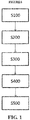
- FIG. 1 is a schematic diagram of control steps of a defrosting control method for a heat pump system according to this application.
- FIG. 1 a schematic diagram of control steps of a defrosting control method for a heat pump system is shown. Specifically, the method at least includes the following steps: in S100, initializing a first default parameter TM n and a second default parameter TN n in a preset defrosting interval indicatrix X when a heat pump system runs; in S200, executing the defrosting cycle when the preset defrosting interval indicatrix X is greater than or equal to a preset constant value, and terminating the defrosting cycle after a defrosting cycle exit condition is met; in S300, obtaining an actual time spent on the defrosting cycle; in S400, comparing the actual time spent on the defrosting cycle with an expected defrosting time, and adjusting the first default parameter and the second default parameter when the actual defrosting time deviates from the expected defrosting time; and in S500, repeating steps S200 to S400.
- a first default parameter and a second default parameter in the preset defrosting interval indicatrix are adjusted when an actual defrosting time deviates from an expected defrosting time, so that a defrosting interval can be adjusted effectively to conform to an actual application situation, thus achieving a balance between unit performance and comfort degree of customers.
- the preset defrosting interval indicatrix X T 1 /TM n +T 2 /TN n , wherein X is greater than or equal to the preset constant value.
- T 1 represents a running time of the heat pump system when an outdoor temperature is greater than or equal to an outdoor temperature preset value
- TM n represents the first default parameter
- T 2 represents a running time of the heat pump system when the outdoor temperature is less than the outdoor temperature preset value
- TN n represents the second default parameter
- n represents the number of executed defrosting cycles.
- a frost layer with a certain thickness is formed more easily.
- a corresponding first default parameter should be set to ensure that the preset defrosting interval indicatrix can be used for indicating an expected defrosting interval when the temperature is higher than the outdoor temperature preset value.
- a corresponding second default parameter should be set to ensure that the preset defrosting interval indicatrix can be used for indicating an expected defrosting interval when the temperature is lower than the outdoor temperature preset value.
- the preset constant value mentioned in the preset defrosting interval indicatrix X is used for providing a normative standard to check whether a variable, i.e., the heat hump actual running time, in the function meets a defrosting requirement.
- the preset constant value is set to 100%. In other words, it is considered that when the running time T 1 of the heat pump system is equal to TM n in a working condition where the outdoor temperature is greater than or equal to the outdoor temperature preset value, a frost situation on the condenser has reached such a degree that defrosting needs to be performed 100% as considered by the designer.
- an optional outdoor temperature preset value is -5°C to -10°C; and/or the first default parameter is 20 to 40; and/or the second default parameter is 40 to 80.
- a group of data is selected from the set protection ranges to illustrate the meaning of the settings.
- the outdoor temperature preset value is set to -8°C
- the first default parameter is set to 30, and the second default parameter is set to 60. That is, when the heat pump system runs at a temperature higher than or equal to -8°C, it can be basically considered that the humidity at this temperature is relatively high, and therefore a frost layer with a certain thickness can be formed on the condenser after a relatively short running time. In this case, a relatively small number, such as 30, should be provided as the first default parameter.
- the control system determines that every time after the heat pump system runs for 30 min at a temperature greater than or equal to -8°C, the control system considers that the frost layer accumulated on the condenser has reached an inappropriate thickness, and a defrosting mode needs to be executed.
- the heat pump system runs at a temperature lower than -8°C, it can be basically considered that the humidity at this temperature is relatively low, and therefore a frost layer with a certain thickness is formed on the condenser only after a relatively long running time. In this case, a relatively large number such as 60 should be provided as the second default parameter. It indicates that every time after the heat pump system runs for 60 min at a temperature lower than -8°C, the control system considers that the frost layer accumulated on the condenser has reached an inappropriate thickness, and a defrosting mode needs to be executed.
- the first default parameter/second default parameter of each execution needs to have a time variation of c preset time units a with respect to the previous first default parameter/second default parameter, that is, the first default parameter/second default parameter of each execution may be increased or decreased by the duration of a*c units with respect to the previous first default parameter/second default parameter.
- the defrosting interval can be increased by adding the duration of a to the first default parameter/second default parameter.
- the preset time unit a is set to 5 min to 10 min, that is, the minimum change unit of the defrosting interval is 5 min to 10 min each time.
- a minimum value is further set for the first default parameter/second default parameter to avoid problems in the first default parameter/second default parameter in some extreme cases or fault conditions, for example, the first default parameter/second default parameter becomes a negative number, or frequent starts and stops caused by an extremely short interval.
- the defrosting control method further includes a plurality of control parameters having meaningful settings, as well as a plurality of control steps.
- the control parameters and control steps will be illustrated as follows.
- a plurality of defrosting cycle exit conditions are set here.
- the condenser temperature is greater than 12°C to 16°C, it can be considered that an expected defrosting effect has been reached, and the defrosting cycle can be exited.
- the actual defrosting time is greater than 6 min to 10 min, it is also necessary to exit the defrosting cycle first and resume heating in consideration that users may feel uncomfortable if heating is off for a long time
- the number n of the executed defrosting cycles returns to zero. That is, the preset defrosting interval indicatrix is initialized, so that it can be applied to the commonest scenario.
- an optional expected defrosting time is 3 min to 4 min, because it is difficult to completely remove the frost layer if the defrosting time is too short, while heating will be off for a long time if the defrosting time is too long, which easily affects comfort degree of customers.
- a heat pump system is further provided, which can use the defrosting control method and therefore can achieve the corresponding technical effect.
- the purpose of the defrosting control method is adjusting the defrosting interval, so that it better conforms to the actual application situation, while the specific defrosting pipeline layout or defrosting means is not limited.
- the heat pump system can have various structures and methods for executing a defrosting cycle. For example, heating can be stopped and a four-way valve can be reversed to introduce a high-temperature gas refrigerant on the condenser side, so as to dissipate heat and defrost.
- a bypass branch can be opened at a vent end of a compressor to introduce a high-temperature gas refrigerant into the condenser side, so as to dissipate heat and defrost. Any embodiment or a combination of the embodiments of this application is fully applicable to these different situations and brings about corresponding technical effects.
Landscapes
- Engineering & Computer Science (AREA)
- Mechanical Engineering (AREA)
- General Engineering & Computer Science (AREA)
- Signal Processing (AREA)
- Chemical & Material Sciences (AREA)
- Combustion & Propulsion (AREA)
- Physics & Mathematics (AREA)
- Fuzzy Systems (AREA)
- Mathematical Physics (AREA)
- Thermal Sciences (AREA)
- Defrosting Systems (AREA)
- Air Conditioning Control Device (AREA)
Abstract
Description
- This application relates to the field of heat pumps, and more specifically, to a defrosting control method for a heat pump system.
- As very mature equipment, heat pump systems are widely applied in commercial buildings, household space, and many other places and can also provide relatively comfortable refrigerating/heating effects. However, engineers in this field are still devoting themselves to optimization and improvement in many aspects, one of which is to control a defrosting time and a defrosting interval.
- Currently, the conventional defrosting control is carried out by setting a preset time interval in a heating mode and starting every defrosting cycle accordingly. This method is usually set for conventional environmental conditions. If the external temperature is relatively low, and humidity is relatively low, the external frosting degree may still be relatively low after the preset time interval. In this case, frequent defrosting affects user experience on one hand and causes energy waste on the other hand. On the contrary, if the external temperature is relatively high, and humidity is relatively high, the external frosting degree may have become very serious before the preset time interval arrives, and therefore defrosting is needed urgently. In this case, the thick frost may affect device performance on one hand, and on the other hand, the subsequent defrosting process also takes a long time, and bad user experience will be caused if the heating mode is off for a long time.
- An objective of this application is to provide a defrosting control method for a heat pump system, through which a defrosting interval can be adjusted.
- Another objective of this application is to provide a heat pump system capable of adjusting a defrosting interval.
- To realize the objectives of this application, according to one aspect of this application, a defrosting control method for a heat pump system is provided, including: in S100, initializing a first default parameter TMn and a second default parameter TNn in a preset defrosting interval indicatrix X when a heat pump system runs, wherein the preset defrosting interval indicatrix X=T1/TMn+T2/TNn, T1 represents a running time of the heat pump system when an outdoor temperature is greater than or equal to an outdoor temperature preset value, T2 represents a running time of the heat pump system when the outdoor temperature is less than the outdoor temperature preset value, and n represents the number of executed defrosting cycles; in S200, executing the defrosting cycle when the preset defrosting interval indicatrix X is greater than or equal to a preset constant value, and terminating the defrosting cycle after a defrosting cycle exit condition is met; in S300, obtaining an actual time spent on the defrosting cycle; in S400, comparing the actual time spent on the defrosting cycle with an expected defrosting time, and adjusting the first default parameter and the second default parameter when the actual defrosting time deviates from the expected defrosting time; and in S500, repeating steps S200 to S400.
- Optionally, the outdoor temperature preset value is -5°C to 10°C; and/or the first default parameter is 20 to 40; and/or the second default parameter is 40 to 80.
- Optionally, when the defrosting cycle is executed for the nth time, TMn=TMn-1+a*c; and/or TNn=TNn-1+a*c, wherein a represents a preset time unit, and c represents a third default parameter.
- Optionally, when the actual defrosting time is less than the expected defrosting time, c=1; and/or when the actual defrosting time is equal to the expected defrosting time, c=0; and/or when the actual defrosting time is greater than the expected defrosting time, c=-1.
- Optionally, the preset time unit a is set to 5 min to 10 min.
- Optionally, when TMn-1+a*c<TMmin, TMn is taken as a minimum value TMmin; and/or when TNn-1+a*c<TNmin, TNn is taken as a minimum value TNmin
- Optionally, TMmin=30 min; and/or TNmin=30 min.
- Optionally, the preset constant value is 100%.
- Optionally, the defrosting cycle exit condition is that a condenser temperature is greater than 12°C to 16°C, or the actual defrosting time is greater than 6 min to 10 min.
- Optionally, the expected defrosting time is 3 min to 4 min.
- Optionally, the number n of executed defrosting cycles returns to zero when a running mode of the heat pump system is switched, or the heat pump system is powered off and restarted.
- To realize the objectives of this application, according to another aspect of this application, a heat pump system is further provided, which performs defrosting control using the defrosting control method described above.
- In the heat pump system and the defrosting control method according to this application, by introducing the restriction of a preset defrosting interval indicatrix X=T1/TMn+T2/TNn, a first default parameter and a second default parameter in the preset defrosting interval indicatrix are adjusted when an actual defrosting time deviates from an expected defrosting time, so that a defrosting interval can be adjusted effectively to conform to an actual application situation, thus achieving a balance between unit performance and comfort degree of customers.
-
FIG. 1 is a schematic diagram of control steps of a defrosting control method for a heat pump system according to this application. - Referring to
FIG. 1 , a schematic diagram of control steps of a defrosting control method for a heat pump system is shown. Specifically, the method at least includes the following steps: in S100, initializing a first default parameter TMn and a second default parameter TNn in a preset defrosting interval indicatrix X when a heat pump system runs; in S200, executing the defrosting cycle when the preset defrosting interval indicatrix X is greater than or equal to a preset constant value, and terminating the defrosting cycle after a defrosting cycle exit condition is met; in S300, obtaining an actual time spent on the defrosting cycle; in S400, comparing the actual time spent on the defrosting cycle with an expected defrosting time, and adjusting the first default parameter and the second default parameter when the actual defrosting time deviates from the expected defrosting time; and in S500, repeating steps S200 to S400. - In the heat pump system and the defrosting control method according to this application, by introducing the restriction of a preset defrosting interval indicatrix, a first default parameter and a second default parameter in the preset defrosting interval indicatrix are adjusted when an actual defrosting time deviates from an expected defrosting time, so that a defrosting interval can be adjusted effectively to conform to an actual application situation, thus achieving a balance between unit performance and comfort degree of customers.
- Specifically, the preset defrosting interval indicatrix X=T1/TMn+T2/TNn, wherein X is greater than or equal to the preset constant value. T1 represents a running time of the heat pump system when an outdoor temperature is greater than or equal to an outdoor temperature preset value; TMn represents the first default parameter; T2 represents a running time of the heat pump system when the outdoor temperature is less than the outdoor temperature preset value; TNn represents the second default parameter; and n represents the number of executed defrosting cycles. When the heat pump system runs at a temperature greater than or equal to a certain outdoor temperature preset value, as the environment temperature is relatively high, the humidity is also relatively high. Therefore, a frost layer with a certain thickness is formed more easily. In this case, a corresponding first default parameter should be set to ensure that the preset defrosting interval indicatrix can be used for indicating an expected defrosting interval when the temperature is higher than the outdoor temperature preset value. In addition, when the heat pump system runs at a temperature lower than a certain outdoor temperature preset value, as the environment temperature is relatively low, the air is dryer and the humidity is also relatively low. Therefore, it is difficult to form a frost layer with a certain thickness. In this case, a corresponding second default parameter should be set to ensure that the preset defrosting interval indicatrix can be used for indicating an expected defrosting interval when the temperature is lower than the outdoor temperature preset value. The preset constant value mentioned in the preset defrosting interval indicatrix X is used for providing a normative standard to check whether a variable, i.e., the heat hump actual running time, in the function meets a defrosting requirement. For example, the preset constant value is set to 100%. In other words, it is considered that when the running time T1 of the heat pump system is equal to TMn in a working condition where the outdoor temperature is greater than or equal to the outdoor temperature preset value, a frost situation on the condenser has reached such a degree that defrosting needs to be performed 100% as considered by the designer. Alternatively, when the running time T2 of the heat pump system is equal to TNn in a working condition where the outdoor temperature is less than the outdoor temperature preset value, a frost situation on the condenser also has reached such a degree that defrosting needs to be performed 100% as considered by the designer. Alternatively, when the running time T1 of the heat pump system is equal to 1/2TMn in a working condition where the outdoor temperature is greater than or equal to the outdoor temperature preset value and the running time T2 of the heat pump system is equal to 1/2TNn in a working condition where the outdoor temperature is less than the outdoor temperature preset value, as X=50%+50%=100%, a frost situation on the condenser also has reached such a degree that defrosting needs to be performed 100% as considered by the designer.
- The parameters in the defined preset defrosting interval indicatrix and effects of the parameters will be described below more intuitively with examples.
- For example, an optional outdoor temperature preset value is -5°C to -10°C; and/or the first default parameter is 20 to 40; and/or the second default parameter is 40 to 80. A group of data is selected from the set protection ranges to illustrate the meaning of the settings. Here, the outdoor temperature preset value is set to -8°C, the first default parameter is set to 30, and the second default parameter is set to 60. That is, when the heat pump system runs at a temperature higher than or equal to -8°C, it can be basically considered that the humidity at this temperature is relatively high, and therefore a frost layer with a certain thickness can be formed on the condenser after a relatively short running time. In this case, a relatively small number, such as 30, should be provided as the first default parameter. It indicates that every time after the heat pump system runs for 30 min at a temperature greater than or equal to -8°C, the control system considers that the frost layer accumulated on the condenser has reached an inappropriate thickness, and a defrosting mode needs to be executed. When the heat pump system runs at a temperature lower than -8°C, it can be basically considered that the humidity at this temperature is relatively low, and therefore a frost layer with a certain thickness is formed on the condenser only after a relatively long running time. In this case, a relatively large number such as 60 should be provided as the second default parameter. It indicates that every time after the heat pump system runs for 60 min at a temperature lower than -8°C, the control system considers that the frost layer accumulated on the condenser has reached an inappropriate thickness, and a defrosting mode needs to be executed.
- An expression of the preset defrosting interval indicatrix has been provided as above. When the defrosting cycle is executed for the nth time, in the corresponding preset defrosting interval indicatrix, the first default parameter TMn= TMn-1+a*c, and the second default parameter TNn=TNn-1+a*c, wherein a represents a preset time unit, and c represents a third default parameter. That is, to make sure that an execution time of the defrosting cycle is in a suitable range, the defrosting interval of each execution needs to be adjusted according to an actual situation. In the expression, the first default parameter/second default parameter of each execution needs to have a time variation of c preset time units a with respect to the previous first default parameter/second default parameter, that is, the first default parameter/second default parameter of each execution may be increased or decreased by the duration of a*c units with respect to the previous first default parameter/second default parameter.
- More specifically, when the actual defrosting time is less than the expected defrosting time, c=1; that is, the defrosting interval can be increased by adding the duration of a to the first default parameter/second default parameter. When the actual defrosting time is equal to the expected defrosting time, c=0; that is, the current defrosting interval is suitable, and the first default parameter/second default parameter can remain unchanged. When the actual defrosting time is greater than the expected defrosting time, c=-1; that is, the defrosting interval can be decreased by subtracting the duration of a from the first default parameter/second default parameter.
- In another aspect, optionally, the preset time unit a is set to 5 min to 10 min, that is, the minimum change unit of the defrosting interval is 5 min to 10 min each time.
- Optionally, a minimum value is further set for the first default parameter/second default parameter to avoid problems in the first default parameter/second default parameter in some extreme cases or fault conditions, for example, the first default parameter/second default parameter becomes a negative number, or frequent starts and stops caused by an extremely short interval. An expression of the minimum value is as follows: when TMn-1+a*c<TMmin, TMn is taken as a minimum value TMmin; and when TNn-1+a*c<TNmin, TNn is taken as a minimum value TNmin. More specifically, the minimum value TMmin=30 min; and the minimum value TNmin=30 min.
- In addition to the expression of the preset defrosting interval indicatrix, the defrosting control method further includes a plurality of control parameters having meaningful settings, as well as a plurality of control steps. The control parameters and control steps will be illustrated as follows.
- For example, a plurality of defrosting cycle exit conditions are set here. On one hand, when the condenser temperature is greater than 12°C to 16°C, it can be considered that an expected defrosting effect has been reached, and the defrosting cycle can be exited. On the other hand, when the actual defrosting time is greater than 6 min to 10 min, it is also necessary to exit the defrosting cycle first and resume heating in consideration that users may feel uncomfortable if heating is off for a long time
- For another example, when a running mode of the heat pump system is switched, or the heat pump system is powered off and restarted, the number n of the executed defrosting cycles returns to zero. That is, the preset defrosting interval indicatrix is initialized, so that it can be applied to the commonest scenario.
- For another example, an optional expected defrosting time is 3 min to 4 min, because it is difficult to completely remove the frost layer if the defrosting time is too short, while heating will be off for a long time if the defrosting time is too long, which easily affects comfort degree of customers.
- Although not shown in the figure, according to another aspect of this application, a heat pump system is further provided, which can use the defrosting control method and therefore can achieve the corresponding technical effect. It should be noted that the purpose of the defrosting control method is adjusting the defrosting interval, so that it better conforms to the actual application situation, while the specific defrosting pipeline layout or defrosting means is not limited.
- In the prior art, the heat pump system can have various structures and methods for executing a defrosting cycle. For example, heating can be stopped and a four-way valve can be reversed to introduce a high-temperature gas refrigerant on the condenser side, so as to dissipate heat and defrost. For another example, a bypass branch can be opened at a vent end of a compressor to introduce a high-temperature gas refrigerant into the condenser side, so as to dissipate heat and defrost. Any embodiment or a combination of the embodiments of this application is fully applicable to these different situations and brings about corresponding technical effects.
- The above examples mainly illustrate the defrosting control method and the heat pump system of this application. Some implementations of this application are described. However, those of ordinary skill in the art should understand that this application can be implemented in many other forms without departing from the subject and scope thereof. Therefore, the displayed examples and implementations are considered as exemplary instead of limitative, and this application can incorporate various modifications and replacements without departing from the scope of this application as defined in the appended claims.
Claims (12)
- A defrosting control method for a heat pump system, comprising:initializing (S100) a first default parameter TMn and a second default parameter TNn in a preset defrosting interval indicatrix X when a heat pump system runs, wherein the preset defrosting interval indicatrix X=T1/TMn+T2/TNn, T1 represents a running time of the heat pump system when an outdoor temperature is greater than or equal to an outdoor temperature preset value, T2 represents a running time of the heat pump system when the outdoor temperature is less than the outdoor temperature preset value, and n represents the number of executed defrosting cycles;executing (S200) the defrosting cycle when the preset defrosting interval indicatrix X is greater than or equal to a preset constant value, and terminating the defrosting cycle after a defrosting cycle exit condition is met;obtaining (S300) an actual time spent on the defrosting cycle;comparing (S400) the actual time spent on the defrosting cycle with an expected defrosting time, and adjusting the first default parameter and the second default parameter when the actual defrosting time deviates from the expected defrosting time; andrepeating (S500) steps S200 to S400.
- The defrosting control method according to Claim 1, wherein the outdoor temperature preset value is -5°C to -10°C; and/or the first default parameter is 20 to 40; and/or the second default parameter is 40 to 80.
- The defrosting control method according to Claims 1 or 2, wherein when the defrosting cycle is executed for the nth time, TMn=TMn-1+a*c; and/or TNn=TNn-1+a*c, wherein a represents a preset time unit, and c represents a third default parameter.
- The defrosting control method according to Claim 3, wherein
when the actual defrosting time is less than the expected defrosting time, c=1; and/or
when the actual defrosting time is equal to the expected defrosting time, c=0; and/or
when the actual defrosting time is greater than the expected defrosting time, c=-1. - The defrosting control method according to Claims 3 or 4, wherein the preset time unit a is set to 5 min to 10 min.
- The defrosting control method according to any of claims 3 to 5, wherein
when TMn-1+a*c<TMmin, TMn is taken as a minimum value TMmin; and/or
when TNn-1+a*c<TNmin, TNn is taken as a minimum value TNmin. - The defrosting control method according to Claim 6, wherein TMmin=30 min; and/or TNmin=30 min.
- The defrosting control method according to any of claims 1 to 7, wherein the preset constant value is 100%.
- The defrosting control method according to any of Claims 1 to 8, wherein the defrosting cycle exit condition is that a condenser temperature is greater than 12°C to 16°C, or the actual defrosting time is greater than 6 min to 10 min.
- The defrosting control method according to any of Claims 1 to 9, wherein the expected defrosting time is 3 min to 4 min.
- The defrosting control method according to any of Claims 1 to 10, wherein the number n of executed defrosting cycles returns to zero when a running mode of the heat pump system is switched, or the heat pump system is powered off and restarted.
- A heat pump system, wherein defrosting control is performed by using the defrosting control method according to any of Claims 1 to 11.
Applications Claiming Priority (1)
| Application Number | Priority Date | Filing Date | Title |
|---|---|---|---|
| CN201810132393.XA CN110131836B (en) | 2018-02-09 | 2018-02-09 | Defrost control method and heat pump system |
Publications (2)
| Publication Number | Publication Date |
|---|---|
| EP3524896A1 true EP3524896A1 (en) | 2019-08-14 |
| EP3524896B1 EP3524896B1 (en) | 2023-06-07 |
Family
ID=65408976
Family Applications (1)
| Application Number | Title | Priority Date | Filing Date |
|---|---|---|---|
| EP19156475.6A Active EP3524896B1 (en) | 2018-02-09 | 2019-02-11 | Defrost control method and heat pump system |
Country Status (4)
| Country | Link |
|---|---|
| US (1) | US12467680B2 (en) |
| EP (1) | EP3524896B1 (en) |
| CN (1) | CN110131836B (en) |
| ES (1) | ES2949418T3 (en) |
Cited By (2)
| Publication number | Priority date | Publication date | Assignee | Title |
|---|---|---|---|---|
| CN113865007A (en) * | 2020-06-30 | 2021-12-31 | 青岛海尔空调器有限总公司 | Air conditioner and control method thereof |
| CN116624973A (en) * | 2023-04-23 | 2023-08-22 | 青岛海尔空调器有限总公司 | Dehumidifier and control method thereof |
Families Citing this family (7)
| Publication number | Priority date | Publication date | Assignee | Title |
|---|---|---|---|---|
| CN110736211B (en) * | 2019-09-26 | 2021-11-23 | 青岛海尔空调器有限总公司 | Control method and control device for defrosting of air conditioner and air conditioner |
| CN110736210B (en) * | 2019-09-26 | 2021-10-29 | 青岛海尔空调器有限总公司 | Control method, control device and air conditioner for air conditioner defrosting |
| CN110736213B (en) * | 2019-09-27 | 2021-11-23 | 青岛海尔空调器有限总公司 | Control method and control device for defrosting of air conditioner and air conditioner |
| CN112815587A (en) * | 2019-11-15 | 2021-05-18 | 广东芬尼克兹节能设备有限公司 | Heat pump defrosting exit control method and device, electronic equipment and storage medium |
| CN113494835A (en) * | 2020-04-08 | 2021-10-12 | 博西华电器(江苏)有限公司 | Refrigerator control method and refrigerator applying same |
| DE102024207921A1 (en) * | 2024-08-21 | 2026-02-26 | Viessmann Holding International GmbH | Method for operating a building's heating system |
| CN119222863B (en) * | 2024-11-12 | 2025-07-08 | 舜虹环境技术(苏州)有限公司 | Defrosting method and system for low-temperature air source unit |
Citations (4)
| Publication number | Priority date | Publication date | Assignee | Title |
|---|---|---|---|---|
| CN105371587A (en) * | 2015-11-20 | 2016-03-02 | 青岛海尔股份有限公司 | Defrosting control method |
| CN105588267A (en) * | 2015-05-29 | 2016-05-18 | 青岛海信日立空调系统有限公司 | Defrosting control method and device for automatically detecting frost quantity of heat pump system |
| WO2017050073A1 (en) * | 2015-09-23 | 2017-03-30 | 广东美的暖通设备有限公司 | Water chiller-heater unit of air cooled heat pump and defrosting control method therefor |
| CN107228451A (en) * | 2017-05-17 | 2017-10-03 | 青岛海尔空调器有限总公司 | Air conditioner defrosting control method |
Family Cites Families (27)
| Publication number | Priority date | Publication date | Assignee | Title |
|---|---|---|---|---|
| US4328680A (en) * | 1980-10-14 | 1982-05-11 | General Electric Company | Heat pump defrost control apparatus |
| US4573326A (en) | 1985-02-04 | 1986-03-04 | American Standard Inc. | Adaptive defrost control for heat pump system |
| US4938027A (en) * | 1989-11-06 | 1990-07-03 | Amana Refrigeration, Inc. | Apparatus and method for defrosting refrigerator in vacation mode |
| US5493867A (en) | 1992-11-18 | 1996-02-27 | Whirlpool Corporation | Fuzzy logic adaptive defrost control |
| US6047557A (en) | 1995-06-07 | 2000-04-11 | Copeland Corporation | Adaptive control for a refrigeration system using pulse width modulated duty cycle scroll compressor |
| US5970726A (en) | 1997-04-08 | 1999-10-26 | Heatcraft Inc. | Defrost control for space cooling system |
| US7228692B2 (en) | 2004-02-11 | 2007-06-12 | Carrier Corporation | Defrost mode for HVAC heat pump systems |
| US9068771B2 (en) | 2006-01-20 | 2015-06-30 | Carrier Corporation | Method for automatically adjusting the defrost interval in a heat pump system |
| JP2009210161A (en) | 2008-02-29 | 2009-09-17 | Sanyo Electric Co Ltd | Equipment control system, control device, and control program |
| US20110209489A1 (en) * | 2010-03-01 | 2011-09-01 | Lawson Sr Reynold Kenneth | Heat pump defrost control |
| CA2828740C (en) | 2011-02-28 | 2016-07-05 | Emerson Electric Co. | Residential solutions hvac monitoring and diagnosis |
| EP2574868B1 (en) | 2011-09-29 | 2019-06-12 | LG Electronics Inc. | Refrigerator |
| CN102519186B (en) * | 2011-12-21 | 2014-08-06 | 青岛海尔空调电子有限公司 | Defrosting method of air conditioner air-cooled heat pump unit and air conditioner air-cooled heat pump unit |
| CN102829527B (en) | 2012-03-20 | 2013-12-04 | 广东志高空调有限公司 | Cloud air conditioning self-adaptive defrosting system |
| CN103574832B (en) | 2012-07-25 | 2016-04-27 | 珠海格力电器股份有限公司 | Control method, device and system for defrosting of air conditioner |
| CN102901182B (en) * | 2012-10-16 | 2015-06-03 | 青岛海尔空调电子有限公司 | Defrosting method for air conditioner |
| US20140352335A1 (en) * | 2013-05-31 | 2014-12-04 | Haier America Research And Development Co., Ltd. | Adaptive defrost |
| KR102129297B1 (en) | 2013-07-29 | 2020-07-03 | 삼성전자주식회사 | Air conditional and method for controlling the same |
| JP5574028B1 (en) | 2013-07-31 | 2014-08-20 | 株式会社富士通ゼネラル | Air conditioner |
| US20150211779A1 (en) * | 2014-01-30 | 2015-07-30 | Trane International Inc. | System and Method of Protecting an HVAC System |
| JP6201872B2 (en) | 2014-04-16 | 2017-09-27 | 三菱電機株式会社 | Air conditioner |
| US10345022B2 (en) * | 2015-08-14 | 2019-07-09 | Mitsubishi Electric Corporation | Air-conditioning apparatus |
| US20170075510A1 (en) | 2015-09-11 | 2017-03-16 | Johnson Controls Technology Company | Thermostat with occupant identity determination features |
| DK178990B1 (en) | 2015-12-29 | 2017-07-31 | Maersk Line As | Fremgangsmåde til bestemmelse af, hvornår en afrimningscyklus i en kølecontainer skal afsluttes |
| CN105605840B (en) * | 2016-02-01 | 2018-06-05 | 浙江丹特卫顿热泵有限公司 | A kind of intelligent defrosting method with learning functionality |
| CN106524412A (en) * | 2016-11-09 | 2017-03-22 | 重庆美的通用制冷设备有限公司 | Air conditioning unit defrosting controlling method and device and air conditioner |
| CN107091548A (en) | 2017-05-23 | 2017-08-25 | 天津大学 | A kind of air source heat pump defrosting control system and method |
-
2018
- 2018-02-09 CN CN201810132393.XA patent/CN110131836B/en active Active
-
2019
- 2019-02-08 US US16/270,833 patent/US12467680B2/en active Active
- 2019-02-11 ES ES19156475T patent/ES2949418T3/en active Active
- 2019-02-11 EP EP19156475.6A patent/EP3524896B1/en active Active
Patent Citations (4)
| Publication number | Priority date | Publication date | Assignee | Title |
|---|---|---|---|---|
| CN105588267A (en) * | 2015-05-29 | 2016-05-18 | 青岛海信日立空调系统有限公司 | Defrosting control method and device for automatically detecting frost quantity of heat pump system |
| WO2017050073A1 (en) * | 2015-09-23 | 2017-03-30 | 广东美的暖通设备有限公司 | Water chiller-heater unit of air cooled heat pump and defrosting control method therefor |
| CN105371587A (en) * | 2015-11-20 | 2016-03-02 | 青岛海尔股份有限公司 | Defrosting control method |
| CN107228451A (en) * | 2017-05-17 | 2017-10-03 | 青岛海尔空调器有限总公司 | Air conditioner defrosting control method |
Cited By (3)
| Publication number | Priority date | Publication date | Assignee | Title |
|---|---|---|---|---|
| CN113865007A (en) * | 2020-06-30 | 2021-12-31 | 青岛海尔空调器有限总公司 | Air conditioner and control method thereof |
| CN113865007B (en) * | 2020-06-30 | 2023-06-23 | 青岛海尔空调器有限总公司 | Air conditioner and its control method |
| CN116624973A (en) * | 2023-04-23 | 2023-08-22 | 青岛海尔空调器有限总公司 | Dehumidifier and control method thereof |
Also Published As
| Publication number | Publication date |
|---|---|
| CN110131836B (en) | 2022-03-15 |
| ES2949418T3 (en) | 2023-09-28 |
| EP3524896B1 (en) | 2023-06-07 |
| CN110131836A (en) | 2019-08-16 |
| US12467680B2 (en) | 2025-11-11 |
| US20190249916A1 (en) | 2019-08-15 |
Similar Documents
| Publication | Publication Date | Title |
|---|---|---|
| EP3524896B1 (en) | Defrost control method and heat pump system | |
| CN109210696B (en) | Control method for anti-freezing protection of air conditioner | |
| CN106839325B (en) | Air conditioner control method, device, and air conditioner | |
| CN107514743B (en) | Air conditioner control method, control device and air conditioner | |
| CN103968497A (en) | Method and device for adjusting running frequency of air conditioner compressor and air conditioner | |
| EP2876384B1 (en) | Air-conditioning apparatus | |
| CN109210699B (en) | Control method of anti-freeze protection of air conditioner | |
| CN112361538B (en) | Oil return control method and device and multi-split system | |
| US9695830B2 (en) | Control device | |
| CN110057025A (en) | Control method, device, computer product and the air-conditioning of air conditioner electronic expansion valve | |
| CN112665204B (en) | Control method and device for double-evaporator air conditioner and double-evaporator air conditioner | |
| EP3828473A1 (en) | Refrigerant flow control method and device for air conditioner and computer storage medium | |
| CN110779183B (en) | Operation control method, device, air conditioner, and storage medium | |
| CN108626855B (en) | Energy-saving comfort control method for variable frequency air conditioning system | |
| CN105157292A (en) | Control method and device for electronic expansion valves of air cooling screw unit | |
| CN112524760A (en) | Method and device for controlling air outlet temperature of air conditioner and air conditioner | |
| EP4033170B1 (en) | Method for controlling balanced frosting of outdoor units in multi-split air-conditioning system | |
| CN111895605B (en) | Control method, device, air conditioner and computer-readable storage medium for air conditioner defrosting | |
| WO2022198979A1 (en) | Control method and apparatus for air conditioner, and air conditioner | |
| CN115751590B (en) | Compressor discharge pressure control method and device, air conditioner and storage medium | |
| CN111023402B (en) | A kind of self-adaptive adjustment method of air conditioning system and air conditioner | |
| CN104374059B (en) | A kind of system capability adjusting method and humidity control system | |
| CN108800438A (en) | Air conditioner inhibits frosting control method | |
| CN111121152B (en) | Multi-connected outdoor unit and fresh air fan mixed connection system and control method thereof | |
| CN115183348A (en) | Dual-system air conditioning unit and control method thereof |
Legal Events
| Date | Code | Title | Description |
|---|---|---|---|
| PUAI | Public reference made under article 153(3) epc to a published international application that has entered the european phase |
Free format text: ORIGINAL CODE: 0009012 |
|
| STAA | Information on the status of an ep patent application or granted ep patent |
Free format text: STATUS: THE APPLICATION HAS BEEN PUBLISHED |
|
| AK | Designated contracting states |
Kind code of ref document: A1 Designated state(s): AL AT BE BG CH CY CZ DE DK EE ES FI FR GB GR HR HU IE IS IT LI LT LU LV MC MK MT NL NO PL PT RO RS SE SI SK SM TR |
|
| AX | Request for extension of the european patent |
Extension state: BA ME |
|
| STAA | Information on the status of an ep patent application or granted ep patent |
Free format text: STATUS: REQUEST FOR EXAMINATION WAS MADE |
|
| 17P | Request for examination filed |
Effective date: 20200213 |
|
| RBV | Designated contracting states (corrected) |
Designated state(s): AL AT BE BG CH CY CZ DE DK EE ES FI FR GB GR HR HU IE IS IT LI LT LU LV MC MK MT NL NO PL PT RO RS SE SI SK SM TR |
|
| STAA | Information on the status of an ep patent application or granted ep patent |
Free format text: STATUS: EXAMINATION IS IN PROGRESS |
|
| RIC1 | Information provided on ipc code assigned before grant |
Ipc: F24F 11/41 20180101ALI20210224BHEP Ipc: F24F 11/42 20180101ALI20210224BHEP Ipc: F24F 11/63 20180101AFI20210224BHEP Ipc: F24F 11/64 20180101ALI20210224BHEP |
|
| 17Q | First examination report despatched |
Effective date: 20210305 |
|
| GRAP | Despatch of communication of intention to grant a patent |
Free format text: ORIGINAL CODE: EPIDOSNIGR1 |
|
| STAA | Information on the status of an ep patent application or granted ep patent |
Free format text: STATUS: GRANT OF PATENT IS INTENDED |
|
| INTG | Intention to grant announced |
Effective date: 20230215 |
|
| GRAS | Grant fee paid |
Free format text: ORIGINAL CODE: EPIDOSNIGR3 |
|
| GRAA | (expected) grant |
Free format text: ORIGINAL CODE: 0009210 |
|
| STAA | Information on the status of an ep patent application or granted ep patent |
Free format text: STATUS: THE PATENT HAS BEEN GRANTED |
|
| AK | Designated contracting states |
Kind code of ref document: B1 Designated state(s): AL AT BE BG CH CY CZ DE DK EE ES FI FR GB GR HR HU IE IS IT LI LT LU LV MC MK MT NL NO PL PT RO RS SE SI SK SM TR |
|
| REG | Reference to a national code |
Ref country code: GB Ref legal event code: FG4D |
|
| REG | Reference to a national code |
Ref country code: CH Ref legal event code: EP Ref country code: AT Ref legal event code: REF Ref document number: 1576177 Country of ref document: AT Kind code of ref document: T Effective date: 20230615 |
|
| REG | Reference to a national code |
Ref country code: DE Ref legal event code: R096 Ref document number: 602019029702 Country of ref document: DE |
|
| P01 | Opt-out of the competence of the unified patent court (upc) registered |
Effective date: 20230527 |
|
| REG | Reference to a national code |
Ref country code: NL Ref legal event code: FP |
|
| REG | Reference to a national code |
Ref country code: LT Ref legal event code: MG9D |
|
| REG | Reference to a national code |
Ref country code: ES Ref legal event code: FG2A Ref document number: 2949418 Country of ref document: ES Kind code of ref document: T3 Effective date: 20230928 |
|
| PG25 | Lapsed in a contracting state [announced via postgrant information from national office to epo] |
Ref country code: SE Free format text: LAPSE BECAUSE OF FAILURE TO SUBMIT A TRANSLATION OF THE DESCRIPTION OR TO PAY THE FEE WITHIN THE PRESCRIBED TIME-LIMIT Effective date: 20230607 Ref country code: NO Free format text: LAPSE BECAUSE OF FAILURE TO SUBMIT A TRANSLATION OF THE DESCRIPTION OR TO PAY THE FEE WITHIN THE PRESCRIBED TIME-LIMIT Effective date: 20230907 |
|
| REG | Reference to a national code |
Ref country code: AT Ref legal event code: MK05 Ref document number: 1576177 Country of ref document: AT Kind code of ref document: T Effective date: 20230607 |
|
| PG25 | Lapsed in a contracting state [announced via postgrant information from national office to epo] |
Ref country code: RS Free format text: LAPSE BECAUSE OF FAILURE TO SUBMIT A TRANSLATION OF THE DESCRIPTION OR TO PAY THE FEE WITHIN THE PRESCRIBED TIME-LIMIT Effective date: 20230607 Ref country code: LV Free format text: LAPSE BECAUSE OF FAILURE TO SUBMIT A TRANSLATION OF THE DESCRIPTION OR TO PAY THE FEE WITHIN THE PRESCRIBED TIME-LIMIT Effective date: 20230607 Ref country code: LT Free format text: LAPSE BECAUSE OF FAILURE TO SUBMIT A TRANSLATION OF THE DESCRIPTION OR TO PAY THE FEE WITHIN THE PRESCRIBED TIME-LIMIT Effective date: 20230607 Ref country code: HR Free format text: LAPSE BECAUSE OF FAILURE TO SUBMIT A TRANSLATION OF THE DESCRIPTION OR TO PAY THE FEE WITHIN THE PRESCRIBED TIME-LIMIT Effective date: 20230607 Ref country code: GR Free format text: LAPSE BECAUSE OF FAILURE TO SUBMIT A TRANSLATION OF THE DESCRIPTION OR TO PAY THE FEE WITHIN THE PRESCRIBED TIME-LIMIT Effective date: 20230908 |
|
| PG25 | Lapsed in a contracting state [announced via postgrant information from national office to epo] |
Ref country code: FI Free format text: LAPSE BECAUSE OF FAILURE TO SUBMIT A TRANSLATION OF THE DESCRIPTION OR TO PAY THE FEE WITHIN THE PRESCRIBED TIME-LIMIT Effective date: 20230607 |
|
| PG25 | Lapsed in a contracting state [announced via postgrant information from national office to epo] |
Ref country code: SK Free format text: LAPSE BECAUSE OF FAILURE TO SUBMIT A TRANSLATION OF THE DESCRIPTION OR TO PAY THE FEE WITHIN THE PRESCRIBED TIME-LIMIT Effective date: 20230607 |
|
| PG25 | Lapsed in a contracting state [announced via postgrant information from national office to epo] |
Ref country code: IS Free format text: LAPSE BECAUSE OF FAILURE TO SUBMIT A TRANSLATION OF THE DESCRIPTION OR TO PAY THE FEE WITHIN THE PRESCRIBED TIME-LIMIT Effective date: 20231007 |
|
| PG25 | Lapsed in a contracting state [announced via postgrant information from national office to epo] |
Ref country code: SM Free format text: LAPSE BECAUSE OF FAILURE TO SUBMIT A TRANSLATION OF THE DESCRIPTION OR TO PAY THE FEE WITHIN THE PRESCRIBED TIME-LIMIT Effective date: 20230607 Ref country code: SK Free format text: LAPSE BECAUSE OF FAILURE TO SUBMIT A TRANSLATION OF THE DESCRIPTION OR TO PAY THE FEE WITHIN THE PRESCRIBED TIME-LIMIT Effective date: 20230607 Ref country code: RO Free format text: LAPSE BECAUSE OF FAILURE TO SUBMIT A TRANSLATION OF THE DESCRIPTION OR TO PAY THE FEE WITHIN THE PRESCRIBED TIME-LIMIT Effective date: 20230607 Ref country code: PT Free format text: LAPSE BECAUSE OF FAILURE TO SUBMIT A TRANSLATION OF THE DESCRIPTION OR TO PAY THE FEE WITHIN THE PRESCRIBED TIME-LIMIT Effective date: 20231009 Ref country code: IS Free format text: LAPSE BECAUSE OF FAILURE TO SUBMIT A TRANSLATION OF THE DESCRIPTION OR TO PAY THE FEE WITHIN THE PRESCRIBED TIME-LIMIT Effective date: 20231007 Ref country code: EE Free format text: LAPSE BECAUSE OF FAILURE TO SUBMIT A TRANSLATION OF THE DESCRIPTION OR TO PAY THE FEE WITHIN THE PRESCRIBED TIME-LIMIT Effective date: 20230607 Ref country code: CZ Free format text: LAPSE BECAUSE OF FAILURE TO SUBMIT A TRANSLATION OF THE DESCRIPTION OR TO PAY THE FEE WITHIN THE PRESCRIBED TIME-LIMIT Effective date: 20230607 Ref country code: AT Free format text: LAPSE BECAUSE OF FAILURE TO SUBMIT A TRANSLATION OF THE DESCRIPTION OR TO PAY THE FEE WITHIN THE PRESCRIBED TIME-LIMIT Effective date: 20230607 |
|
| PG25 | Lapsed in a contracting state [announced via postgrant information from national office to epo] |
Ref country code: PL Free format text: LAPSE BECAUSE OF FAILURE TO SUBMIT A TRANSLATION OF THE DESCRIPTION OR TO PAY THE FEE WITHIN THE PRESCRIBED TIME-LIMIT Effective date: 20230607 |
|
| REG | Reference to a national code |
Ref country code: DE Ref legal event code: R097 Ref document number: 602019029702 Country of ref document: DE |
|
| PLBE | No opposition filed within time limit |
Free format text: ORIGINAL CODE: 0009261 |
|
| STAA | Information on the status of an ep patent application or granted ep patent |
Free format text: STATUS: NO OPPOSITION FILED WITHIN TIME LIMIT |
|
| PG25 | Lapsed in a contracting state [announced via postgrant information from national office to epo] |
Ref country code: DK Free format text: LAPSE BECAUSE OF FAILURE TO SUBMIT A TRANSLATION OF THE DESCRIPTION OR TO PAY THE FEE WITHIN THE PRESCRIBED TIME-LIMIT Effective date: 20230607 |
|
| PG25 | Lapsed in a contracting state [announced via postgrant information from national office to epo] |
Ref country code: SI Free format text: LAPSE BECAUSE OF FAILURE TO SUBMIT A TRANSLATION OF THE DESCRIPTION OR TO PAY THE FEE WITHIN THE PRESCRIBED TIME-LIMIT Effective date: 20230607 |
|
| 26N | No opposition filed |
Effective date: 20240308 |
|
| PG25 | Lapsed in a contracting state [announced via postgrant information from national office to epo] |
Ref country code: SI Free format text: LAPSE BECAUSE OF FAILURE TO SUBMIT A TRANSLATION OF THE DESCRIPTION OR TO PAY THE FEE WITHIN THE PRESCRIBED TIME-LIMIT Effective date: 20230607 |
|
| PG25 | Lapsed in a contracting state [announced via postgrant information from national office to epo] |
Ref country code: MC Free format text: LAPSE BECAUSE OF FAILURE TO SUBMIT A TRANSLATION OF THE DESCRIPTION OR TO PAY THE FEE WITHIN THE PRESCRIBED TIME-LIMIT Effective date: 20230607 |
|
| REG | Reference to a national code |
Ref country code: CH Ref legal event code: PL |
|
| PG25 | Lapsed in a contracting state [announced via postgrant information from national office to epo] |
Ref country code: LU Free format text: LAPSE BECAUSE OF NON-PAYMENT OF DUE FEES Effective date: 20240211 |
|
| PG25 | Lapsed in a contracting state [announced via postgrant information from national office to epo] |
Ref country code: CH Free format text: LAPSE BECAUSE OF NON-PAYMENT OF DUE FEES Effective date: 20240229 |
|
| GBPC | Gb: european patent ceased through non-payment of renewal fee |
Effective date: 20240211 |
|
| PG25 | Lapsed in a contracting state [announced via postgrant information from national office to epo] |
Ref country code: LU Free format text: LAPSE BECAUSE OF NON-PAYMENT OF DUE FEES Effective date: 20240211 Ref country code: CH Free format text: LAPSE BECAUSE OF NON-PAYMENT OF DUE FEES Effective date: 20240229 |
|
| PG25 | Lapsed in a contracting state [announced via postgrant information from national office to epo] |
Ref country code: BG Free format text: LAPSE BECAUSE OF FAILURE TO SUBMIT A TRANSLATION OF THE DESCRIPTION OR TO PAY THE FEE WITHIN THE PRESCRIBED TIME-LIMIT Effective date: 20230607 |
|
| PG25 | Lapsed in a contracting state [announced via postgrant information from national office to epo] |
Ref country code: BG Free format text: LAPSE BECAUSE OF FAILURE TO SUBMIT A TRANSLATION OF THE DESCRIPTION OR TO PAY THE FEE WITHIN THE PRESCRIBED TIME-LIMIT Effective date: 20230607 |
|
| PG25 | Lapsed in a contracting state [announced via postgrant information from national office to epo] |
Ref country code: GB Free format text: LAPSE BECAUSE OF NON-PAYMENT OF DUE FEES Effective date: 20240211 |
|
| PG25 | Lapsed in a contracting state [announced via postgrant information from national office to epo] |
Ref country code: IE Free format text: LAPSE BECAUSE OF NON-PAYMENT OF DUE FEES Effective date: 20240211 |
|
| PG25 | Lapsed in a contracting state [announced via postgrant information from national office to epo] |
Ref country code: IE Free format text: LAPSE BECAUSE OF NON-PAYMENT OF DUE FEES Effective date: 20240211 Ref country code: GB Free format text: LAPSE BECAUSE OF NON-PAYMENT OF DUE FEES Effective date: 20240211 |
|
| PGFP | Annual fee paid to national office [announced via postgrant information from national office to epo] |
Ref country code: NL Payment date: 20250121 Year of fee payment: 7 |
|
| PGFP | Annual fee paid to national office [announced via postgrant information from national office to epo] |
Ref country code: ES Payment date: 20250303 Year of fee payment: 7 |
|
| PGFP | Annual fee paid to national office [announced via postgrant information from national office to epo] |
Ref country code: BE Payment date: 20250121 Year of fee payment: 7 |
|
| PGFP | Annual fee paid to national office [announced via postgrant information from national office to epo] |
Ref country code: IT Payment date: 20250121 Year of fee payment: 7 |
|
| PG25 | Lapsed in a contracting state [announced via postgrant information from national office to epo] |
Ref country code: CY Free format text: LAPSE BECAUSE OF FAILURE TO SUBMIT A TRANSLATION OF THE DESCRIPTION OR TO PAY THE FEE WITHIN THE PRESCRIBED TIME-LIMIT; INVALID AB INITIO Effective date: 20190211 |
|
| PG25 | Lapsed in a contracting state [announced via postgrant information from national office to epo] |
Ref country code: HU Free format text: LAPSE BECAUSE OF FAILURE TO SUBMIT A TRANSLATION OF THE DESCRIPTION OR TO PAY THE FEE WITHIN THE PRESCRIBED TIME-LIMIT; INVALID AB INITIO Effective date: 20190211 |
|
| PG25 | Lapsed in a contracting state [announced via postgrant information from national office to epo] |
Ref country code: TR Free format text: LAPSE BECAUSE OF FAILURE TO SUBMIT A TRANSLATION OF THE DESCRIPTION OR TO PAY THE FEE WITHIN THE PRESCRIBED TIME-LIMIT Effective date: 20230607 |
|
| PGFP | Annual fee paid to national office [announced via postgrant information from national office to epo] |
Ref country code: DE Payment date: 20260121 Year of fee payment: 8 |
|
| PGFP | Annual fee paid to national office [announced via postgrant information from national office to epo] |
Ref country code: FR Payment date: 20260121 Year of fee payment: 8 |