EP3524562A1 - Protective sleeve for elevator load bearing member - Google Patents
Protective sleeve for elevator load bearing member Download PDFInfo
- Publication number
- EP3524562A1 EP3524562A1 EP19156212.3A EP19156212A EP3524562A1 EP 3524562 A1 EP3524562 A1 EP 3524562A1 EP 19156212 A EP19156212 A EP 19156212A EP 3524562 A1 EP3524562 A1 EP 3524562A1
- Authority
- EP
- European Patent Office
- Prior art keywords
- sleeve
- load bearing
- bearing member
- hoistway
- elevator system
- Prior art date
- Legal status (The legal status is an assumption and is not a legal conclusion. Google has not performed a legal analysis and makes no representation as to the accuracy of the status listed.)
- Granted
Links
Images




Classifications
-
- B—PERFORMING OPERATIONS; TRANSPORTING
- B66—HOISTING; LIFTING; HAULING
- B66B—ELEVATORS; ESCALATORS OR MOVING WALKWAYS
- B66B7/00—Other common features of elevators
- B66B7/02—Guideways; Guides
- B66B7/023—Mounting means therefor
- B66B7/027—Mounting means therefor for mounting auxiliary devices
-
- B—PERFORMING OPERATIONS; TRANSPORTING
- B66—HOISTING; LIFTING; HAULING
- B66B—ELEVATORS; ESCALATORS OR MOVING WALKWAYS
- B66B5/00—Applications of checking, fault-correcting, or safety devices in elevators
-
- B—PERFORMING OPERATIONS; TRANSPORTING
- B66—HOISTING; LIFTING; HAULING
- B66B—ELEVATORS; ESCALATORS OR MOVING WALKWAYS
- B66B5/00—Applications of checking, fault-correcting, or safety devices in elevators
- B66B5/0087—Devices facilitating maintenance, repair or inspection tasks
-
- B—PERFORMING OPERATIONS; TRANSPORTING
- B66—HOISTING; LIFTING; HAULING
- B66B—ELEVATORS; ESCALATORS OR MOVING WALKWAYS
- B66B7/00—Other common features of elevators
- B66B7/06—Arrangements of ropes or cables
-
- B—PERFORMING OPERATIONS; TRANSPORTING
- B66—HOISTING; LIFTING; HAULING
- B66B—ELEVATORS; ESCALATORS OR MOVING WALKWAYS
- B66B7/00—Other common features of elevators
- B66B7/06—Arrangements of ropes or cables
- B66B7/068—Cable weight compensating devices
-
- B—PERFORMING OPERATIONS; TRANSPORTING
- B66—HOISTING; LIFTING; HAULING
- B66B—ELEVATORS; ESCALATORS OR MOVING WALKWAYS
- B66B7/00—Other common features of elevators
- B66B7/06—Arrangements of ropes or cables
- B66B7/10—Arrangements of ropes or cables for equalising rope or cable tension
-
- B—PERFORMING OPERATIONS; TRANSPORTING
- B66—HOISTING; LIFTING; HAULING
- B66B—ELEVATORS; ESCALATORS OR MOVING WALKWAYS
- B66B7/00—Other common features of elevators
- B66B7/06—Arrangements of ropes or cables
- B66B7/062—Belts
-
- B—PERFORMING OPERATIONS; TRANSPORTING
- B66—HOISTING; LIFTING; HAULING
- B66B—ELEVATORS; ESCALATORS OR MOVING WALKWAYS
- B66B7/00—Other common features of elevators
- B66B7/12—Checking, lubricating, or cleaning means for ropes, cables or guides
- B66B7/1207—Checking means
- B66B7/1215—Checking means specially adapted for ropes or cables
- B66B7/1223—Checking means specially adapted for ropes or cables by analysing electric variables
Definitions
- Exemplary embodiments pertain to the art of elevator systems. More particularly, the present disclosure relates to installation and maintenance of elevator systems.
- Elevator systems are useful for carrying passengers, cargo, or both, between various levels in a building.
- Some elevators are traction based and utilize load bearing members such as belts for supporting the elevator car and achieving the desired movement and positioning of the elevator car.
- a scaffold is used to install components in the hoistway, such as rails, controllers and the like. Then, the elevator car and load bearing members are installed thus completing installation of the elevator system.
- components in the hoistway such as rails, controllers and the like.
- the elevator car and load bearing members are installed thus completing installation of the elevator system.
- the drive system of the elevator system such as the machine and the load bearing members are installed in the hoistway and connected to the elevator car.
- the elevator car or a dedicated installation car, are utilized as an installation platform to install the remaining components in the hoistway.
- components such as rail sections are installed from the installation platform at a first location.
- the installation platform is then moved along the hoistway via the machine and load bearing members to this first location and the elevator system components are installed at a second location from the installation platform. This movement and installation continues along the hoistway.
- the installation mechanics conduct operations such as welding and grinding at the installation platform to install rails and other components. With such operations taking place in close proximity to the load bearing members, the load bearing members are exposed to, for example, weld slag, concrete debris, and other construction materials that can damage the load bearing members.
- a protective cover for a load bearing member of an elevator system includes a sleeve wrapped around a perimeter of the load bearing member, the sleeve configured to protect the load bearing member from debris damage during installation or maintenance operation of the elevator system, and configured to slide along a length direction of the load bearing member.
- a tether is configured to connect the sleeve to a working platform.
- a closure secures the sleeve at the load bearing member.
- the closure is one of a hook and loop fastener, a button, a snap, a magnet, or a tie.
- the sleeve is formed of a non-flammable fabric.
- the tether includes a breakaway feature.
- the breakaway feature is a breakaway buckle.
- an elevator system in another embodiment, includes a hoistway, an elevator car located in the hoistway, an elevator load bearing member operably connected to the elevator car to suspend and/or drive the elevator car along the hoistway, and a guide rail installed in the hoistway to guide movement of the elevator car along the hoistway.
- a protective cover for the load bearing member includes a sleeve wrapped around a perimeter of the load bearing member. The sleeve is configured to protect the load bearing member from debris damage during installation or maintenance operation of the elevator system, and configured to slide along a length direction of the load bearing member.
- a tether is configured to connect the sleeve to the elevator car.
- a closure secures the sleeve at the load bearing member.
- the closure is one of a hook and loop fastener, a button, a snap, a magnet, or a tie.
- the sleeve is formed of a non-flammable fabric.
- the tether includes a breakaway feature.
- the breakaway feature is a breakaway buckle.
- the breakaway feature disconnects the sleeve from the elevator car as a result of a tether tension exceeding a threshold.
- the load bearing member is a belt.
- a method of performing installation or maintenance on hoistway components for an elevator system includes installing a sleeve around a portion of a load bearing member of an elevator system, connecting the sleeve to a working platform via a tether, and performing one or more installation or maintenance operations at a first hoistway location via the working platform.
- the sleeve protects the load bearing member from damage from the one or more installation or maintenance operations.
- the working platform is moved from the first hoistway location to a second hoistway location, and the sleeve is moved along the load bearing member via the tether connection between the sleeve and the working platform.
- a connection of the sleeve to the working platform is broken by a breakaway element disposed at the tether.
- the one or more installation or maintenance operations include one or more of welding or grinding.
- the sleeve is formed from non-flammable material.
- FIG. 1 Shown in FIG. 1 is a schematic view of an exemplary traction elevator system 10.
- the elevator system 10 includes an elevator car 14 operatively suspended or supported in a hoistway 12 with one or more belts 16.
- the elevator car 14 travels along the hoistway 12 along guide rails 60 extending along the hoistway.
- the guide rails 60 are supported in the hoistway 12 by rail supports 62.
- the one or more belts 16 interact with sheaves 18 and 52 to be routed around various components of the elevator system 10.
- Sheave 18 is configured as a diverter, deflector or idler sheave and sheave 52 is configured as a traction sheave 52, driven by a machine 50.
- Movement of the traction sheave 52 by the machine 50 drives, moves and/or propels (through traction) the one or more belts 16 that are routed around the traction sheave 52.
- Diverter, deflector or idler sheaves 18 are not driven by a machine 50, but help guide the one or more belts 16 around the various components of the elevator system 10.
- the one or more belts 16 could also be connected to a counterweight 22, which is used to help balance the elevator system 10 and reduce the difference in belt tension on both sides of the traction sheave during operation.
- the sheaves 18 and 52 each have a diameter, which may be the same or different from each other.
- the elevator system 10 could use two or more belts 16 for suspending and/or driving the elevator car 14
- the elevator system 10 could have various configurations such that either both sides of the one or more belts 16 engage the sheaves 18, 52 or only one side of the one or more belts 16 engages the sheaves 18, 52.
- the belts 16 are constructed to meet belt life requirements and have smooth operation, while being sufficiently strong to be capable of meeting strength requirements for suspending and/or driving the elevator car 14 and counterweight 22. Further, while the description herein utilizes the term "belt”, one skilled in the art will readily appreciate that the present disclosure may be readily applied to other configurations of load bearing members, such as ropes.
- FIG. 2 provides a cross-sectional schematic of an exemplary belt 16 construction or design.
- the belt 16 includes a plurality of tension members 24 extending longitudinally along the belt 16 and arranged across a belt width 26.
- the tension members 24 are at least partially enclosed in a jacket 28 to restrain movement of the tension members 24 in the belt 16 and to protect the tension members 24.
- the jacket 28 defines a traction side 30 configured to interact with a corresponding surface of the traction sheave 52.
- the belt 16 has a belt width 26 and a belt thickness 32, with an aspect ratio of belt width 26 to belt thickness 32 greater than one.
- the belt 16 further includes a back side 34 opposite the traction side 30 and belt edges 36 extending between the traction side 30 and the back side 34. While five tension members 24 are illustrated in the embodiment of FIG. 2 , other embodiments may include other numbers of tension members 24, for example, 6, 10 or 12 tension members 24. Further, while the tension members 24 of the embodiment of FIG. 2 are substantially identical, in other embodiments, the tension members 24 may differ in construction from one another.
- the tension member 24 may be a plurality of wires 38, for example, steel wires 38, which in some embodiments are formed into one or more strands 40.
- the tension member 24 may include a plurality of fibers 42, such as carbon fiber, glass fiber, basalt fiber, liquid crystal polymer fiber, or aramid fiber, disposed in a matrix material 44. Materials such as but no limited to polyurethane, vinyl ester, or epoxy may be utilized as the matrix material 44.
- the jacket 28 may be formed from materials such as the elastomers of thermoplastic and thermosetting polyurethanes, thermoplastic polyester elastomers, ethylene propylene diene elastomer, chloroprene, chlorosulfonyl polyethylene, ethylene vinyl acetate, polyamide, polypropylene, butyl rubber, acrylonitrile butadiene rubber, styrene butadiene rubber, acrylic elastomer, fluoroelastomer, silicone elastomer, polyolefin elastomer, styrene block and diene elastomer, natural rubber, or combinations thereof.
- materials such as the elastomers of thermoplastic and thermosetting polyurethanes, thermoplastic polyester elastomers, ethylene propylene diene elastomer, chloroprene, chlorosulfonyl polyethylene, ethylene vinyl acetate, polyamide, polypropylene, butyl rubber, acrylon
- jacket 28 Other materials may be used to form the jacket 28 if they are adequate to meet the required functions of the belt 16.
- a primary function of the jacket 28 is to provide a sufficient coefficient of friction between the belt 16 and the traction sheave 52 to produce a desired amount of traction therebetween.
- the jacket 28 should also transmit the traction loads to the tension members 24.
- the jacket 28 should be wear resistant and protect the tension members 24 from impact damage, exposure to environmental factors, such as chemicals, for example.
- the elevator car 14 is utilized as an installation/maintenance platform from which a technician installs/repairs components of the elevator system 10, such as guide rails 60, rail brackets 62 or the like in the hoistway 12.
- the technician may use a car roof 64 of the elevator car as the working platform.
- the technician may alternatively use a dedicated working vehicle.
- the machine 50 and traction sheave 52 are installed in the hoistway 12, typically at a top of the hoistway 12.
- the counterweight 22 is then positioned at the top of its travel path in the hoistway 12.
- the elevator car 14 is positioned at a bottom of the hoistway 12, also referred to as a pit.
- the belt or belts 16 are installed and routed over the traction sheave 52 and any other sheaves 18 of the elevator system 10, such that the elevator car 14 can now be moved along the hoistway by the belts 16 via the sheaves 18, 52.
- the technician installs/repairs guide rails 60, rail brackets 62 and/or other hoistway components along a first hoistway portion 66.
- the elevator car 14 is moved to the first hoistway portion 66 utilizing the guide rails 60 installed.
- the technician may then install guide rails 60, rail brackets 62 and/or other hoistway components at a second hoistway portion 68 above the first hoistway portion 66.
- the elevator car 14 may then be moved to the second hoistway portion 68. This process is repeated upward along the hoistway.
- a belt sleeve 70 is installed over the belt 16 to protect the belt 16 from damage during installation/maintenance of hoistway components.
- the belt sleeve 70 extend partially along a length of the belt 16 and wrap around the belt 16.
- the belt sleeve 70 utilizes a closure 72 such as a hook and loop fastener, a button, a snap, a magnet, a tie, or the like to secure the belt sleeve 70 at the belt 16. Once installed, the belt sleeve 70 is slidable along the belt 16.
- the belt sleeve 70 is formed of a non-flammable fabric, such as a fiberglass fabric, and may include other elements such as impact resistant materials, such as Kevlar, Silica fabric, Nomex Aramid fabric or the like.
- each belt 16 is enclosed by an individual belt sleeve 70.
- a belt sleeve 70 may enclose more than one belt 16.
- Each belt sleeve 70 includes a tether 74 to connect the belt sleeve 70 to the elevator car 14, as illustrated in FIG. 6 . Connecting the belt sleeve 70 to the elevator car 14 allows the belt sleeve 70 to slide along the belt 16 as the elevator car 14 moves along the hoistway 12 during the installation process, so the belt sleeve 70 protects the portion of the belt 16 in proximity to the installation processes being performed by the technician.
- a length of the tether 74 is adjustable to accommodate various hoistway sizes and layouts.
- the belt sleeve 70 further includes a breakaway feature, such as a breakaway buckle 76 along the tether 74. If the tension on the tether 74 increases to above a threshold, the breakaway buckle 76 will open, thus severing the tether connection between the belt sleeve 70 and the elevator car 14. Utilizing a breakaway feature such as the breakaway buckle 76 prevents damage to the belts 16 during the installation process if, for example, the belt sleeve 70 resists sliding along the belt 16 or if a force is applied to the tether 74 increasing its tension.
- a breakaway feature such as the breakaway buckle 76 prevents damage to the belts 16 during the installation process if, for example, the belt sleeve 70 resists sliding along the belt 16 or if a force is applied to the tether 74 increasing its tension.
- the belt sleeve 70 disclosed herein provides protection to the belts 16 during installation and/or maintenance of hoistway components.
- the belt sleeve 70 aids in ensuring the robust quality and life expectancy of the belt 16 by preventing damage to the belt 16 from processes such as welding or grinding in the hoistway that causes premature belt failure and costly belt replacements.
- the location of the guide rails 60 can vary depending on the layout of the elevator system. Therefore the belt protection needs to be flexible, adjustable and easy to apply.
- the belt sleeve 70 disclosed herein fits a wide range of belt sizes, can be utilized with a wide variety of elevator system layouts and configurations. Further, the belt sleeve 70 is configured to move along the belt 16 and is easy to install at the belt 16.
Landscapes
- Lift-Guide Devices, And Elevator Ropes And Cables (AREA)
Abstract
Description
- Exemplary embodiments pertain to the art of elevator systems. More particularly, the present disclosure relates to installation and maintenance of elevator systems.
- Elevator systems are useful for carrying passengers, cargo, or both, between various levels in a building. Some elevators are traction based and utilize load bearing members such as belts for supporting the elevator car and achieving the desired movement and positioning of the elevator car.
- In installation of some elevator systems, a scaffold is used to install components in the hoistway, such as rails, controllers and the like. Then, the elevator car and load bearing members are installed thus completing installation of the elevator system. With high rise systems, in particular, installation and use of scaffolding for elevator system component installation in the hoistway can be cumbersome and inefficient.
- In other configurations, the drive system of the elevator system, such as the machine and the load bearing members are installed in the hoistway and connected to the elevator car. The elevator car, or a dedicated installation car, are utilized as an installation platform to install the remaining components in the hoistway. Starting at the bottom, or alternatively the top, of the hoistway, components such as rail sections are installed from the installation platform at a first location. The installation platform is then moved along the hoistway via the machine and load bearing members to this first location and the elevator system components are installed at a second location from the installation platform. This movement and installation continues along the hoistway.
- The installation mechanics conduct operations such as welding and grinding at the installation platform to install rails and other components. With such operations taking place in close proximity to the load bearing members, the load bearing members are exposed to, for example, weld slag, concrete debris, and other construction materials that can damage the load bearing members.
- In one embodiment, a protective cover for a load bearing member of an elevator system includes a sleeve wrapped around a perimeter of the load bearing member, the sleeve configured to protect the load bearing member from debris damage during installation or maintenance operation of the elevator system, and configured to slide along a length direction of the load bearing member. A tether is configured to connect the sleeve to a working platform.
- Additionally or alternatively, in this or other embodiments a closure secures the sleeve at the load bearing member.
- Additionally or alternatively, in this or other embodiments the closure is one of a hook and loop fastener, a button, a snap, a magnet, or a tie.
- Additionally or alternatively, in this or other embodiments the sleeve is formed of a non-flammable fabric.
- Additionally or alternatively, in this or other embodiments the tether includes a breakaway feature.
- Additionally or alternatively, in this or other embodiments the breakaway feature is a breakaway buckle.
- In another embodiment, an elevator system includes a hoistway, an elevator car located in the hoistway, an elevator load bearing member operably connected to the elevator car to suspend and/or drive the elevator car along the hoistway, and a guide rail installed in the hoistway to guide movement of the elevator car along the hoistway. A protective cover for the load bearing member includes a sleeve wrapped around a perimeter of the load bearing member. The sleeve is configured to protect the load bearing member from debris damage during installation or maintenance operation of the elevator system, and configured to slide along a length direction of the load bearing member. A tether is configured to connect the sleeve to the elevator car.
- Additionally or alternatively, in this or other embodiments a closure secures the sleeve at the load bearing member.
- Additionally or alternatively, in this or other embodiments the closure is one of a hook and loop fastener, a button, a snap, a magnet, or a tie.
- Additionally or alternatively, in this or other embodiments the sleeve is formed of a non-flammable fabric.
- Additionally or alternatively, in this or other embodiments the tether includes a breakaway feature.
- Additionally or alternatively, in this or other embodiments the breakaway feature is a breakaway buckle.
- Additionally or alternatively, in this or other embodiments the breakaway feature disconnects the sleeve from the elevator car as a result of a tether tension exceeding a threshold.
- Additionally or alternatively, in this or other embodiments the load bearing member is a belt.
- In yet another embodiment, a method of performing installation or maintenance on hoistway components for an elevator system includes installing a sleeve around a portion of a load bearing member of an elevator system, connecting the sleeve to a working platform via a tether, and performing one or more installation or maintenance operations at a first hoistway location via the working platform. The sleeve protects the load bearing member from damage from the one or more installation or maintenance operations.
- Additionally or alternatively, in this or other embodiments the working platform is moved from the first hoistway location to a second hoistway location, and the sleeve is moved along the load bearing member via the tether connection between the sleeve and the working platform.
- Additionally or alternatively, in this or other embodiments a connection of the sleeve to the working platform is broken by a breakaway element disposed at the tether.
- Additionally or alternatively, in this or other embodiments the one or more installation or maintenance operations include one or more of welding or grinding.
- Additionally or alternatively, in this or other embodiments the sleeve is formed from non-flammable material.
- The following descriptions should not be considered limiting in any way. With reference to the accompanying drawings, like elements are numbered alike:
-
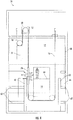
FIG. 1 is a schematic illustration of an embodiment of an elevator system; -
FIG. 2 is cross-sectional view of an embodiment of a belt for an elevator system; -
FIG. 3A is a cross-sectional view of an embodiment of a tension member of a belt; -
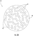
FIG. 3B is a cross-sectional view of another embodiment of a tension member of a belt; -
FIG. 4 is a schematic illustration of an embodiment of an elevator system including a protective sleeve; -
FIG. 5 is an illustration of an embodiment of an elevator load bearing member with a protective sleeve; and -
FIG. 6 is an illustration of an embodiment of a connection of a protective sleeve to an elevator car. - A detailed description of one or more embodiments of the disclosed apparatus and method are presented herein by way of exemplification and not limitation with reference to the Figures.
- Shown in
FIG. 1 is a schematic view of an exemplarytraction elevator system 10. Theelevator system 10 includes anelevator car 14 operatively suspended or supported in ahoistway 12 with one ormore belts 16. Theelevator car 14 travels along thehoistway 12 alongguide rails 60 extending along the hoistway. In some embodiments, theguide rails 60 are supported in thehoistway 12 by rail supports 62. The one ormore belts 16 interact withsheaves elevator system 10. Sheave 18 is configured as a diverter, deflector or idler sheave andsheave 52 is configured as atraction sheave 52, driven by amachine 50. Movement of thetraction sheave 52 by themachine 50 drives, moves and/or propels (through traction) the one ormore belts 16 that are routed around thetraction sheave 52. Diverter, deflector oridler sheaves 18 are not driven by amachine 50, but help guide the one ormore belts 16 around the various components of theelevator system 10. The one ormore belts 16 could also be connected to acounterweight 22, which is used to help balance theelevator system 10 and reduce the difference in belt tension on both sides of the traction sheave during operation. Thesheaves elevator system 10 could use two ormore belts 16 for suspending and/or driving theelevator car 14 In addition, theelevator system 10 could have various configurations such that either both sides of the one ormore belts 16 engage thesheaves more belts 16 engages thesheaves - The
belts 16 are constructed to meet belt life requirements and have smooth operation, while being sufficiently strong to be capable of meeting strength requirements for suspending and/or driving theelevator car 14 andcounterweight 22. Further, while the description herein utilizes the term "belt", one skilled in the art will readily appreciate that the present disclosure may be readily applied to other configurations of load bearing members, such as ropes. -
FIG. 2 provides a cross-sectional schematic of anexemplary belt 16 construction or design. Thebelt 16 includes a plurality oftension members 24 extending longitudinally along thebelt 16 and arranged across abelt width 26. Thetension members 24 are at least partially enclosed in ajacket 28 to restrain movement of thetension members 24 in thebelt 16 and to protect thetension members 24. Thejacket 28 defines atraction side 30 configured to interact with a corresponding surface of thetraction sheave 52. - The
belt 16 has abelt width 26 and abelt thickness 32, with an aspect ratio ofbelt width 26 tobelt thickness 32 greater than one. Thebelt 16 further includes aback side 34 opposite thetraction side 30 and belt edges 36 extending between thetraction side 30 and theback side 34. While fivetension members 24 are illustrated in the embodiment ofFIG. 2 , other embodiments may include other numbers oftension members 24, for example, 6, 10 or 12tension members 24. Further, while thetension members 24 of the embodiment ofFIG. 2 are substantially identical, in other embodiments, thetension members 24 may differ in construction from one another. - Referring now to
FIG. 3A , thetension member 24 may be a plurality ofwires 38, for example,steel wires 38, which in some embodiments are formed into one ormore strands 40. In other embodiments, such as shown inFIG. 3B , thetension member 24 may include a plurality offibers 42, such as carbon fiber, glass fiber, basalt fiber, liquid crystal polymer fiber, or aramid fiber, disposed in amatrix material 44. Materials such as but no limited to polyurethane, vinyl ester, or epoxy may be utilized as thematrix material 44. - Referring again to
FIG. 2 , thejacket 28 may be formed from materials such as the elastomers of thermoplastic and thermosetting polyurethanes, thermoplastic polyester elastomers, ethylene propylene diene elastomer, chloroprene, chlorosulfonyl polyethylene, ethylene vinyl acetate, polyamide, polypropylene, butyl rubber, acrylonitrile butadiene rubber, styrene butadiene rubber, acrylic elastomer, fluoroelastomer, silicone elastomer, polyolefin elastomer, styrene block and diene elastomer, natural rubber, or combinations thereof. Other materials may be used to form thejacket 28 if they are adequate to meet the required functions of thebelt 16. For example, a primary function of thejacket 28 is to provide a sufficient coefficient of friction between thebelt 16 and thetraction sheave 52 to produce a desired amount of traction therebetween. Thejacket 28 should also transmit the traction loads to thetension members 24. In addition, thejacket 28 should be wear resistant and protect thetension members 24 from impact damage, exposure to environmental factors, such as chemicals, for example. - Referring now to
FIG. 4 , in some embodiments theelevator car 14 is utilized as an installation/maintenance platform from which a technician installs/repairs components of theelevator system 10, such asguide rails 60,rail brackets 62 or the like in thehoistway 12. For example, the technician may use acar roof 64 of the elevator car as the working platform. In other embodiments, the technician may alternatively use a dedicated working vehicle. In such a method, themachine 50 and traction sheave 52 are installed in thehoistway 12, typically at a top of thehoistway 12. Thecounterweight 22 is then positioned at the top of its travel path in thehoistway 12. Theelevator car 14 is positioned at a bottom of thehoistway 12, also referred to as a pit. Once theelevator car 14 is positioned, the belt orbelts 16 are installed and routed over thetraction sheave 52 and anyother sheaves 18 of theelevator system 10, such that theelevator car 14 can now be moved along the hoistway by thebelts 16 via thesheaves - Utilizing the working platform, the technician installs/
repairs guide rails 60,rail brackets 62 and/or other hoistway components along afirst hoistway portion 66. Once completed, theelevator car 14 is moved to thefirst hoistway portion 66 utilizing the guide rails 60 installed. The technician may then installguide rails 60,rail brackets 62 and/or other hoistway components at asecond hoistway portion 68 above thefirst hoistway portion 66. Theelevator car 14 may then be moved to thesecond hoistway portion 68. This process is repeated upward along the hoistway. - During installation/maintenance of the guide rails 60,
rail brackets 62 and/or other hoistway components, the technician may perform processes such as welding or grinding which produce debris such as slag, chips, sparks, and the like, that may damage thebelts 16, which are in close proximity to the work being performed. Referring now toFIG. 5 , abelt sleeve 70 is installed over thebelt 16 to protect thebelt 16 from damage during installation/maintenance of hoistway components. Thebelt sleeve 70 extend partially along a length of thebelt 16 and wrap around thebelt 16. Thebelt sleeve 70 utilizes aclosure 72 such as a hook and loop fastener, a button, a snap, a magnet, a tie, or the like to secure thebelt sleeve 70 at thebelt 16. Once installed, thebelt sleeve 70 is slidable along thebelt 16. Thebelt sleeve 70 is formed of a non-flammable fabric, such as a fiberglass fabric, and may include other elements such as impact resistant materials, such as Kevlar, Silica fabric, Nomex Aramid fabric or the like. - In
elevator systems 10 withmultiple belts 16, such as shown inFIG. 5 , eachbelt 16 is enclosed by anindividual belt sleeve 70. Alternatively, in other embodiments, abelt sleeve 70 may enclose more than onebelt 16. Eachbelt sleeve 70 includes atether 74 to connect thebelt sleeve 70 to theelevator car 14, as illustrated inFIG. 6 . Connecting thebelt sleeve 70 to theelevator car 14 allows thebelt sleeve 70 to slide along thebelt 16 as theelevator car 14 moves along thehoistway 12 during the installation process, so thebelt sleeve 70 protects the portion of thebelt 16 in proximity to the installation processes being performed by the technician. In some embodiments, a length of thetether 74 is adjustable to accommodate various hoistway sizes and layouts. - The
belt sleeve 70 further includes a breakaway feature, such as abreakaway buckle 76 along thetether 74. If the tension on thetether 74 increases to above a threshold, thebreakaway buckle 76 will open, thus severing the tether connection between thebelt sleeve 70 and theelevator car 14. Utilizing a breakaway feature such as thebreakaway buckle 76 prevents damage to thebelts 16 during the installation process if, for example, thebelt sleeve 70 resists sliding along thebelt 16 or if a force is applied to thetether 74 increasing its tension. - The
belt sleeve 70 disclosed herein provides protection to thebelts 16 during installation and/or maintenance of hoistway components. Thebelt sleeve 70 aids in ensuring the robust quality and life expectancy of thebelt 16 by preventing damage to thebelt 16 from processes such as welding or grinding in the hoistway that causes premature belt failure and costly belt replacements. The location of the guide rails 60 can vary depending on the layout of the elevator system. Therefore the belt protection needs to be flexible, adjustable and easy to apply. Thebelt sleeve 70 disclosed herein fits a wide range of belt sizes, can be utilized with a wide variety of elevator system layouts and configurations. Further, thebelt sleeve 70 is configured to move along thebelt 16 and is easy to install at thebelt 16. - The term "about" is intended to include the degree of error associated with measurement of the particular quantity based upon the equipment available at the time of filing the application.
- The terminology used herein is for the purpose of describing particular embodiments only and is not intended to be limiting of the present disclosure. As used herein, the singular forms "a", "an" and "the" are intended to include the plural forms as well, unless the context clearly indicates otherwise. It will be further understood that the terms "comprises" and/or "comprising," when used in this specification, specify the presence of stated features, integers, steps, operations, elements, and/or components, but do not preclude the presence or addition of one or more other features, integers, steps, operations, element components, and/or groups thereof.
- While the present disclosure has been described with reference to an exemplary embodiment or embodiments, it will be understood by those skilled in the art that various changes may be made and equivalents may be substituted for elements thereof without departing from the scope of the present disclosure. In addition, many modifications may be made to adapt a particular situation or material to the teachings of the present disclosure without departing from the essential scope thereof. Therefore, it is intended that the present disclosure not be limited to the particular embodiment disclosed as the best mode contemplated for carrying out this present disclosure, but that the present disclosure will include all embodiments falling within the scope of the claims.
Claims (15)
- A protective cover for a load bearing member of an elevator system, comprising:a sleeve wrapped around a perimeter of the load bearing member, the sleeve configured to protect the load bearing member from debris damage during installation or maintenance operation of the elevator system, and configured to slide along a length direction of the load bearing member; anda tether configured to connect the sleeve to a working platform.
- The protective cover of claim 1, further comprising a closure to secure the sleeve at the load bearing member; and preferably
wherein the closure is one of a hook and loop fastener, a button, a snap, a magnet, or a tie. - The protective cover of claim 1 or 2, wherein the sleeve is formed of a non-flammable fabric.
- The protective cover of any preceding claim, wherein the tether includes a breakaway feature; and preferably
wherein the breakaway feature is a breakaway buckle. - An elevator system, comprising:a hoistway;an elevator car disposed in the hoistway;an elevator load bearing member operably connected to the elevator car to suspend and/or drive the elevator car along the hoistway;a guide rail installed in the hoistway to guide movement of the elevator car along the hoistway; anda protective cover for the load bearing member, the protective cover including:a sleeve wrapped around a perimeter of the load bearing member, the sleeve configured to protect the load bearing member from debris damage during installation or maintenance operation of the elevator system, and configured to slide along a length direction of the load bearing member; anda tether configured to connect the sleeve to the elevator car.
- The elevator system of claim 5, further comprising a closure to secure the sleeve at the load bearing member; and preferably
wherein the closure is one of a hook and loop fastener, a button, a snap, a magnet, or a tie. - The elevator system of claim 5 or 6, wherein the sleeve is formed of a non-flammable fabric.
- The elevator system of claim 5, 6 or 7, wherein the tether includes a breakaway feature; and preferably
wherein the breakaway feature is a breakaway buckle. - The elevator system of claim 8, wherein the breakaway feature disconnects the sleeve from the elevator car as a result of a tether tension exceeding a threshold.
- The elevator system of any of claims 5 to 9, wherein the load bearing member is a belt.
- A method of performing installation or maintenance on hoistway components for an elevator system, comprising:installing a sleeve around a portion of a load bearing member of an elevator system;connecting the sleeve to a working platform via a tether; andperforming one or more installation or maintenance operations at a first hoistway location via the working platform, the sleeve protecting the load bearing member from damage from the one or more installation or maintenance operations.
- The method of claim 11, further comprising:moving the working platform from the first hoistway location to a second hoistway location; andmoving the sleeve along the load bearing member via the tether connection between the sleeve and the working platform.
- The method of claim 11 or 12, further comprising breaking a connection of the sleeve to the working platform by a breakaway element disposed at the tether.
- The method of claim 11, 12 or 13, wherein the one or more installation or maintenance operations include one or more of welding or grinding.
- The method of any of claims 11 to 14, wherein the sleeve is formed from non-flammable material.
Applications Claiming Priority (1)
| Application Number | Priority Date | Filing Date | Title |
|---|---|---|---|
| US15/891,661 US11014783B2 (en) | 2018-02-08 | 2018-02-08 | Protective sleeve for elevator belt |
Publications (2)
| Publication Number | Publication Date |
|---|---|
| EP3524562A1 true EP3524562A1 (en) | 2019-08-14 |
| EP3524562B1 EP3524562B1 (en) | 2020-12-30 |
Family
ID=65365863
Family Applications (1)
| Application Number | Title | Priority Date | Filing Date |
|---|---|---|---|
| EP19156212.3A Active EP3524562B1 (en) | 2018-02-08 | 2019-02-08 | Protective cover for elevator load bearing member |
Country Status (3)
| Country | Link |
|---|---|
| US (1) | US11014783B2 (en) |
| EP (1) | EP3524562B1 (en) |
| CN (1) | CN110127474B (en) |
Families Citing this family (6)
| Publication number | Priority date | Publication date | Assignee | Title |
|---|---|---|---|---|
| US10974929B2 (en) * | 2016-11-07 | 2021-04-13 | Otis Elevator Company | Load bearing member for an elevator system having an elastomer and phosphonate blended bonding agent |
| KR102623974B1 (en) * | 2017-11-10 | 2024-01-11 | 오티스 엘리베이터 컴파니 | Elevator system belt |
| AU2019295892B2 (en) * | 2018-06-28 | 2022-03-31 | Inventio Ag | Lift system with a protective screen |
| US12288376B2 (en) | 2020-03-27 | 2025-04-29 | Washington University | Systems and methods for defending against physical attacks on image classification |
| JP7515309B2 (en) * | 2020-06-05 | 2024-07-12 | 三菱電機ビルソリューションズ株式会社 | See-through elevator |
| CN113526311B (en) * | 2021-06-28 | 2023-02-03 | 嘉世达电梯有限公司 | Large-tonnage traction machine with self-locking protection function for elevator |
Citations (2)
| Publication number | Priority date | Publication date | Assignee | Title |
|---|---|---|---|---|
| JPH04109975U (en) * | 1990-11-26 | 1992-09-24 | 三菱電機ビルテクノサ−ビス株式会社 | Elevator main rope protection cover |
| JP2016060551A (en) * | 2014-09-12 | 2016-04-25 | 株式会社日立ビルシステム | Jig tool fall prevention device |
Family Cites Families (32)
| Publication number | Priority date | Publication date | Assignee | Title |
|---|---|---|---|---|
| US4058186A (en) | 1976-05-28 | 1977-11-15 | Westinghouse Electric Corporation | Elevator system with retainer device for plurality of traveling cables |
| US4071124A (en) | 1976-08-26 | 1978-01-31 | Price Donald L | Electrical power supply method and system for open pit mining equipment |
| USH702H (en) | 1987-12-15 | 1989-11-07 | Otis Elevator Company | Controlling the motion of a compensating rope in an elevator |
| US5080199A (en) | 1990-09-24 | 1992-01-14 | Siecor Corporation | Elevator cable hanger |
| US5086880A (en) | 1990-10-10 | 1992-02-11 | Otis Elevator Company | Elevator traveling cable grip |
| FI91849C (en) * | 1993-09-10 | 1994-08-25 | Kone Oy | Method for attaching and adjusting guides |
| JPH0912247A (en) * | 1995-06-28 | 1997-01-14 | Mitsubishi Denki Bill Techno Service Kk | Elevator main wire rope oiling jig |
| US6234277B1 (en) * | 1999-05-07 | 2001-05-22 | Draka Elevator Products, Inc. | Cable sway reduction device |
| JP4278255B2 (en) * | 1999-12-27 | 2009-06-10 | 東芝エレベータ株式会社 | Concentrator of fluorescent lamp abnormality detector |
| US6364575B1 (en) | 2000-09-07 | 2002-04-02 | Michael S. Bradley | Underwater pile repair jacket form |
| US6481537B1 (en) | 2001-08-27 | 2002-11-19 | Otis Elevator Company | Rooftop safety apparatus for elevator servicing |
| US6786306B2 (en) | 2002-04-17 | 2004-09-07 | James L. Tiner | Elevator mechanism |
| JP4225883B2 (en) | 2003-12-01 | 2009-02-18 | 三菱電機ビルテクノサービス株式会社 | Device for preventing catching of moving cables for elevators |
| US20050189176A1 (en) | 2004-02-10 | 2005-09-01 | Demeyer Gerald | Safety harness with removable outer shell |
| JP2006193257A (en) | 2005-01-12 | 2006-07-27 | Toshiba Elevator Co Ltd | Elevator rope holding device, and installing method thereof |
| CN1990371B (en) | 2005-12-27 | 2010-07-21 | 上海三菱电梯有限公司 | The method of elevator installation and the lifting system used in it |
| US8191323B2 (en) | 2006-03-16 | 2012-06-05 | Turner Bruce H | Cable protection sleeve for building framing |
| JP2007276991A (en) | 2006-04-11 | 2007-10-25 | Mitsubishi Electric Corp | Elevator control cable holding device |
| JP2008030898A (en) | 2006-07-28 | 2008-02-14 | Mitsubishi Electric Corp | Elevator car equipment |
| US7393157B1 (en) | 2006-08-02 | 2008-07-01 | Macias Richard A | Timber pile protection apparatus and method |
| GB2453567B (en) | 2007-10-11 | 2012-04-25 | Trelleborg Crp Ltd | Clamp |
| US20090301822A1 (en) | 2008-06-05 | 2009-12-10 | Laszlo Keszthelyi | Cable hanging system |
| JP2012500169A (en) * | 2008-08-15 | 2012-01-05 | オーチス エレベータ カンパニー | Cord and polymer jacket assembly having an adhesion enhancer in the polymer jacket material |
| US8479887B2 (en) * | 2008-08-15 | 2013-07-09 | Otis Elevator Company | Cord and polymer jacket assembly having a flame retardant in the polymer jacket material |
| JP2010189146A (en) | 2009-02-18 | 2010-09-02 | Mitsubishi Electric Corp | Elevator control cable protective device |
| US8517301B1 (en) | 2010-06-21 | 2013-08-27 | Serias Design LLC | Aircraft ground maintenance tether assembly |
| EP2802523A4 (en) | 2012-01-10 | 2016-11-09 | Otis Elevator Co | Elevator travelling cable protection |
| CN202766013U (en) * | 2012-08-06 | 2013-03-06 | 吴江信谊精密五金有限公司 | Elevator traction rope protective guard |
| JP6013222B2 (en) | 2013-02-19 | 2016-10-25 | 株式会社日立製作所 | Elevator |
| DE102014113514A1 (en) | 2014-09-18 | 2016-03-24 | Thyssenkrupp Ag | elevator system |
| CN106144839B (en) * | 2016-08-31 | 2018-11-27 | 天津市奥瑞克电梯有限公司 | Hoist ropes shield |
| US10730721B2 (en) * | 2018-03-02 | 2020-08-04 | Otis Elevator Company | Rope cleaning device |
-
2018
- 2018-02-08 US US15/891,661 patent/US11014783B2/en active Active
-
2019
- 2019-02-08 EP EP19156212.3A patent/EP3524562B1/en active Active
- 2019-02-11 CN CN201910110137.5A patent/CN110127474B/en active Active
Patent Citations (2)
| Publication number | Priority date | Publication date | Assignee | Title |
|---|---|---|---|---|
| JPH04109975U (en) * | 1990-11-26 | 1992-09-24 | 三菱電機ビルテクノサ−ビス株式会社 | Elevator main rope protection cover |
| JP2016060551A (en) * | 2014-09-12 | 2016-04-25 | 株式会社日立ビルシステム | Jig tool fall prevention device |
Also Published As
| Publication number | Publication date |
|---|---|
| US11014783B2 (en) | 2021-05-25 |
| CN110127474A (en) | 2019-08-16 |
| EP3524562B1 (en) | 2020-12-30 |
| US20190241401A1 (en) | 2019-08-08 |
| CN110127474B (en) | 2021-08-10 |
Similar Documents
| Publication | Publication Date | Title |
|---|---|---|
| EP3524562B1 (en) | Protective cover for elevator load bearing member | |
| EP3447019B1 (en) | Belt with self-extinguishing layer and method of making | |
| AU2018202605B2 (en) | Tension member for elevator system belt | |
| AU2018202726B2 (en) | Elevator system belt with fabric tension member | |
| EP3403977B1 (en) | Tension member for elevator system belt | |
| AU2018202655B2 (en) | Tension member for elevator system belt | |
| EP3447018A1 (en) | Self-extinguishing load bearing member for elevator system | |
| US20110108372A1 (en) | Tension member and polymer jacket assembly including a geometry stabilizer in the jacket | |
| KR20190017678A (en) | Load bearing member for lifting system | |
| US11713211B2 (en) | Elevator belt surface protection for installation | |
| EP3640190B1 (en) | Elevator system tension member surface anomoly detection | |
| US10858780B2 (en) | Composite elevator system tension member | |
| EP3789336A1 (en) | Tension member and belt for elevator system | |
| EP3450377B1 (en) | Sheave for belt with profile tracking features | |
| EP3424863A1 (en) | Multiple leaders for load bearing member sway reduction |
Legal Events
| Date | Code | Title | Description |
|---|---|---|---|
| PUAI | Public reference made under article 153(3) epc to a published international application that has entered the european phase |
Free format text: ORIGINAL CODE: 0009012 |
|
| STAA | Information on the status of an ep patent application or granted ep patent |
Free format text: STATUS: THE APPLICATION HAS BEEN PUBLISHED |
|
| AK | Designated contracting states |
Kind code of ref document: A1 Designated state(s): AL AT BE BG CH CY CZ DE DK EE ES FI FR GB GR HR HU IE IS IT LI LT LU LV MC MK MT NL NO PL PT RO RS SE SI SK SM TR |
|
| AX | Request for extension of the european patent |
Extension state: BA ME |
|
| STAA | Information on the status of an ep patent application or granted ep patent |
Free format text: STATUS: REQUEST FOR EXAMINATION WAS MADE |
|
| 17P | Request for examination filed |
Effective date: 20200214 |
|
| RBV | Designated contracting states (corrected) |
Designated state(s): AL AT BE BG CH CY CZ DE DK EE ES FI FR GB GR HR HU IE IS IT LI LT LU LV MC MK MT NL NO PL PT RO RS SE SI SK SM TR |
|
| GRAP | Despatch of communication of intention to grant a patent |
Free format text: ORIGINAL CODE: EPIDOSNIGR1 |
|
| STAA | Information on the status of an ep patent application or granted ep patent |
Free format text: STATUS: GRANT OF PATENT IS INTENDED |
|
| INTG | Intention to grant announced |
Effective date: 20200529 |
|
| GRAJ | Information related to disapproval of communication of intention to grant by the applicant or resumption of examination proceedings by the epo deleted |
Free format text: ORIGINAL CODE: EPIDOSDIGR1 |
|
| STAA | Information on the status of an ep patent application or granted ep patent |
Free format text: STATUS: REQUEST FOR EXAMINATION WAS MADE |
|
| GRAP | Despatch of communication of intention to grant a patent |
Free format text: ORIGINAL CODE: EPIDOSNIGR1 |
|
| STAA | Information on the status of an ep patent application or granted ep patent |
Free format text: STATUS: GRANT OF PATENT IS INTENDED |
|
| INTC | Intention to grant announced (deleted) | ||
| INTG | Intention to grant announced |
Effective date: 20200729 |
|
| GRAS | Grant fee paid |
Free format text: ORIGINAL CODE: EPIDOSNIGR3 |
|
| GRAA | (expected) grant |
Free format text: ORIGINAL CODE: 0009210 |
|
| STAA | Information on the status of an ep patent application or granted ep patent |
Free format text: STATUS: THE PATENT HAS BEEN GRANTED |
|
| AK | Designated contracting states |
Kind code of ref document: B1 Designated state(s): AL AT BE BG CH CY CZ DE DK EE ES FI FR GB GR HR HU IE IS IT LI LT LU LV MC MK MT NL NO PL PT RO RS SE SI SK SM TR |
|
| REG | Reference to a national code |
Ref country code: GB Ref legal event code: FG4D |
|
| REG | Reference to a national code |
Ref country code: AT Ref legal event code: REF Ref document number: 1349747 Country of ref document: AT Kind code of ref document: T Effective date: 20210115 |
|
| REG | Reference to a national code |
Ref country code: DE Ref legal event code: R096 Ref document number: 602019001907 Country of ref document: DE |
|
| REG | Reference to a national code |
Ref country code: IE Ref legal event code: FG4D |
|
| PG25 | Lapsed in a contracting state [announced via postgrant information from national office to epo] |
Ref country code: GR Free format text: LAPSE BECAUSE OF FAILURE TO SUBMIT A TRANSLATION OF THE DESCRIPTION OR TO PAY THE FEE WITHIN THE PRESCRIBED TIME-LIMIT Effective date: 20210331 Ref country code: NO Free format text: LAPSE BECAUSE OF FAILURE TO SUBMIT A TRANSLATION OF THE DESCRIPTION OR TO PAY THE FEE WITHIN THE PRESCRIBED TIME-LIMIT Effective date: 20210330 Ref country code: RS Free format text: LAPSE BECAUSE OF FAILURE TO SUBMIT A TRANSLATION OF THE DESCRIPTION OR TO PAY THE FEE WITHIN THE PRESCRIBED TIME-LIMIT Effective date: 20201230 Ref country code: FI Free format text: LAPSE BECAUSE OF FAILURE TO SUBMIT A TRANSLATION OF THE DESCRIPTION OR TO PAY THE FEE WITHIN THE PRESCRIBED TIME-LIMIT Effective date: 20201230 |
|
| REG | Reference to a national code |
Ref country code: AT Ref legal event code: MK05 Ref document number: 1349747 Country of ref document: AT Kind code of ref document: T Effective date: 20201230 |
|
| PG25 | Lapsed in a contracting state [announced via postgrant information from national office to epo] |
Ref country code: LV Free format text: LAPSE BECAUSE OF FAILURE TO SUBMIT A TRANSLATION OF THE DESCRIPTION OR TO PAY THE FEE WITHIN THE PRESCRIBED TIME-LIMIT Effective date: 20201230 Ref country code: SE Free format text: LAPSE BECAUSE OF FAILURE TO SUBMIT A TRANSLATION OF THE DESCRIPTION OR TO PAY THE FEE WITHIN THE PRESCRIBED TIME-LIMIT Effective date: 20201230 Ref country code: BG Free format text: LAPSE BECAUSE OF FAILURE TO SUBMIT A TRANSLATION OF THE DESCRIPTION OR TO PAY THE FEE WITHIN THE PRESCRIBED TIME-LIMIT Effective date: 20210330 |
|
| REG | Reference to a national code |
Ref country code: NL Ref legal event code: MP Effective date: 20201230 |
|
| PG25 | Lapsed in a contracting state [announced via postgrant information from national office to epo] |
Ref country code: HR Free format text: LAPSE BECAUSE OF FAILURE TO SUBMIT A TRANSLATION OF THE DESCRIPTION OR TO PAY THE FEE WITHIN THE PRESCRIBED TIME-LIMIT Effective date: 20201230 |
|
| REG | Reference to a national code |
Ref country code: LT Ref legal event code: MG9D |
|
| PG25 | Lapsed in a contracting state [announced via postgrant information from national office to epo] |
Ref country code: CZ Free format text: LAPSE BECAUSE OF FAILURE TO SUBMIT A TRANSLATION OF THE DESCRIPTION OR TO PAY THE FEE WITHIN THE PRESCRIBED TIME-LIMIT Effective date: 20201230 Ref country code: SK Free format text: LAPSE BECAUSE OF FAILURE TO SUBMIT A TRANSLATION OF THE DESCRIPTION OR TO PAY THE FEE WITHIN THE PRESCRIBED TIME-LIMIT Effective date: 20201230 Ref country code: EE Free format text: LAPSE BECAUSE OF FAILURE TO SUBMIT A TRANSLATION OF THE DESCRIPTION OR TO PAY THE FEE WITHIN THE PRESCRIBED TIME-LIMIT Effective date: 20201230 Ref country code: RO Free format text: LAPSE BECAUSE OF FAILURE TO SUBMIT A TRANSLATION OF THE DESCRIPTION OR TO PAY THE FEE WITHIN THE PRESCRIBED TIME-LIMIT Effective date: 20201230 Ref country code: PT Free format text: LAPSE BECAUSE OF FAILURE TO SUBMIT A TRANSLATION OF THE DESCRIPTION OR TO PAY THE FEE WITHIN THE PRESCRIBED TIME-LIMIT Effective date: 20210430 Ref country code: LT Free format text: LAPSE BECAUSE OF FAILURE TO SUBMIT A TRANSLATION OF THE DESCRIPTION OR TO PAY THE FEE WITHIN THE PRESCRIBED TIME-LIMIT Effective date: 20201230 |
|
| PG25 | Lapsed in a contracting state [announced via postgrant information from national office to epo] |
Ref country code: PL Free format text: LAPSE BECAUSE OF FAILURE TO SUBMIT A TRANSLATION OF THE DESCRIPTION OR TO PAY THE FEE WITHIN THE PRESCRIBED TIME-LIMIT Effective date: 20201230 Ref country code: AT Free format text: LAPSE BECAUSE OF FAILURE TO SUBMIT A TRANSLATION OF THE DESCRIPTION OR TO PAY THE FEE WITHIN THE PRESCRIBED TIME-LIMIT Effective date: 20201230 |
|
| PG25 | Lapsed in a contracting state [announced via postgrant information from national office to epo] |
Ref country code: IS Free format text: LAPSE BECAUSE OF FAILURE TO SUBMIT A TRANSLATION OF THE DESCRIPTION OR TO PAY THE FEE WITHIN THE PRESCRIBED TIME-LIMIT Effective date: 20210430 Ref country code: MC Free format text: LAPSE BECAUSE OF FAILURE TO SUBMIT A TRANSLATION OF THE DESCRIPTION OR TO PAY THE FEE WITHIN THE PRESCRIBED TIME-LIMIT Effective date: 20201230 |
|
| REG | Reference to a national code |
Ref country code: DE Ref legal event code: R097 Ref document number: 602019001907 Country of ref document: DE |
|
| REG | Reference to a national code |
Ref country code: BE Ref legal event code: MM Effective date: 20210228 |
|
| PG25 | Lapsed in a contracting state [announced via postgrant information from national office to epo] |
Ref country code: IT Free format text: LAPSE BECAUSE OF FAILURE TO SUBMIT A TRANSLATION OF THE DESCRIPTION OR TO PAY THE FEE WITHIN THE PRESCRIBED TIME-LIMIT Effective date: 20201230 Ref country code: LU Free format text: LAPSE BECAUSE OF NON-PAYMENT OF DUE FEES Effective date: 20210208 Ref country code: AL Free format text: LAPSE BECAUSE OF FAILURE TO SUBMIT A TRANSLATION OF THE DESCRIPTION OR TO PAY THE FEE WITHIN THE PRESCRIBED TIME-LIMIT Effective date: 20201230 |
|
| PLBE | No opposition filed within time limit |
Free format text: ORIGINAL CODE: 0009261 |
|
| STAA | Information on the status of an ep patent application or granted ep patent |
Free format text: STATUS: NO OPPOSITION FILED WITHIN TIME LIMIT |
|
| PG25 | Lapsed in a contracting state [announced via postgrant information from national office to epo] |
Ref country code: DK Free format text: LAPSE BECAUSE OF FAILURE TO SUBMIT A TRANSLATION OF THE DESCRIPTION OR TO PAY THE FEE WITHIN THE PRESCRIBED TIME-LIMIT Effective date: 20201230 |
|
| 26N | No opposition filed |
Effective date: 20211001 |
|
| PG25 | Lapsed in a contracting state [announced via postgrant information from national office to epo] |
Ref country code: IE Free format text: LAPSE BECAUSE OF NON-PAYMENT OF DUE FEES Effective date: 20210208 Ref country code: ES Free format text: LAPSE BECAUSE OF FAILURE TO SUBMIT A TRANSLATION OF THE DESCRIPTION OR TO PAY THE FEE WITHIN THE PRESCRIBED TIME-LIMIT Effective date: 20201230 |
|
| PG25 | Lapsed in a contracting state [announced via postgrant information from national office to epo] |
Ref country code: SI Free format text: LAPSE BECAUSE OF FAILURE TO SUBMIT A TRANSLATION OF THE DESCRIPTION OR TO PAY THE FEE WITHIN THE PRESCRIBED TIME-LIMIT Effective date: 20201230 |
|
| PG25 | Lapsed in a contracting state [announced via postgrant information from national office to epo] |
Ref country code: IS Free format text: LAPSE BECAUSE OF FAILURE TO SUBMIT A TRANSLATION OF THE DESCRIPTION OR TO PAY THE FEE WITHIN THE PRESCRIBED TIME-LIMIT Effective date: 20210430 |
|
| PG25 | Lapsed in a contracting state [announced via postgrant information from national office to epo] |
Ref country code: BE Free format text: LAPSE BECAUSE OF NON-PAYMENT OF DUE FEES Effective date: 20210228 |
|
| REG | Reference to a national code |
Ref country code: CH Ref legal event code: PL |
|
| PG25 | Lapsed in a contracting state [announced via postgrant information from national office to epo] |
Ref country code: LI Free format text: LAPSE BECAUSE OF NON-PAYMENT OF DUE FEES Effective date: 20220228 Ref country code: CH Free format text: LAPSE BECAUSE OF NON-PAYMENT OF DUE FEES Effective date: 20220228 |
|
| PG25 | Lapsed in a contracting state [announced via postgrant information from national office to epo] |
Ref country code: NL Free format text: LAPSE BECAUSE OF NON-PAYMENT OF DUE FEES Effective date: 20201230 Ref country code: CY Free format text: LAPSE BECAUSE OF FAILURE TO SUBMIT A TRANSLATION OF THE DESCRIPTION OR TO PAY THE FEE WITHIN THE PRESCRIBED TIME-LIMIT Effective date: 20201230 |
|
| PG25 | Lapsed in a contracting state [announced via postgrant information from national office to epo] |
Ref country code: SM Free format text: LAPSE BECAUSE OF FAILURE TO SUBMIT A TRANSLATION OF THE DESCRIPTION OR TO PAY THE FEE WITHIN THE PRESCRIBED TIME-LIMIT Effective date: 20201230 Ref country code: HU Free format text: LAPSE BECAUSE OF FAILURE TO SUBMIT A TRANSLATION OF THE DESCRIPTION OR TO PAY THE FEE WITHIN THE PRESCRIBED TIME-LIMIT; INVALID AB INITIO Effective date: 20190208 |
|
| GBPC | Gb: european patent ceased through non-payment of renewal fee |
Effective date: 20230208 |
|
| PG25 | Lapsed in a contracting state [announced via postgrant information from national office to epo] |
Ref country code: GB Free format text: LAPSE BECAUSE OF NON-PAYMENT OF DUE FEES Effective date: 20230208 |
|
| PG25 | Lapsed in a contracting state [announced via postgrant information from national office to epo] |
Ref country code: GB Free format text: LAPSE BECAUSE OF NON-PAYMENT OF DUE FEES Effective date: 20230208 |
|
| PG25 | Lapsed in a contracting state [announced via postgrant information from national office to epo] |
Ref country code: MK Free format text: LAPSE BECAUSE OF FAILURE TO SUBMIT A TRANSLATION OF THE DESCRIPTION OR TO PAY THE FEE WITHIN THE PRESCRIBED TIME-LIMIT Effective date: 20201230 |
|
| PG25 | Lapsed in a contracting state [announced via postgrant information from national office to epo] |
Ref country code: MT Free format text: LAPSE BECAUSE OF FAILURE TO SUBMIT A TRANSLATION OF THE DESCRIPTION OR TO PAY THE FEE WITHIN THE PRESCRIBED TIME-LIMIT Effective date: 20201230 |
|
| PG25 | Lapsed in a contracting state [announced via postgrant information from national office to epo] |
Ref country code: TR Free format text: LAPSE BECAUSE OF FAILURE TO SUBMIT A TRANSLATION OF THE DESCRIPTION OR TO PAY THE FEE WITHIN THE PRESCRIBED TIME-LIMIT Effective date: 20201230 |
|
| PGFP | Annual fee paid to national office [announced via postgrant information from national office to epo] |
Ref country code: DE Payment date: 20260121 Year of fee payment: 8 |
|
| PGFP | Annual fee paid to national office [announced via postgrant information from national office to epo] |
Ref country code: FR Payment date: 20260121 Year of fee payment: 8 |