EP3524450A1 - Arm component and manufacturing method therefor - Google Patents
Arm component and manufacturing method therefor Download PDFInfo
- Publication number
- EP3524450A1 EP3524450A1 EP19150792.0A EP19150792A EP3524450A1 EP 3524450 A1 EP3524450 A1 EP 3524450A1 EP 19150792 A EP19150792 A EP 19150792A EP 3524450 A1 EP3524450 A1 EP 3524450A1
- Authority
- EP
- European Patent Office
- Prior art keywords
- arm component
- cross
- arm
- component
- underfill
- Prior art date
- Legal status (The legal status is an assumption and is not a legal conclusion. Google has not performed a legal analysis and makes no representation as to the accuracy of the status listed.)
- Granted
Links
Images



Classifications
-
- B—PERFORMING OPERATIONS; TRANSPORTING
- B60—VEHICLES IN GENERAL
- B60G—VEHICLE SUSPENSION ARRANGEMENTS
- B60G7/00—Pivoted suspension arms; Accessories thereof
- B60G7/001—Suspension arms, e.g. constructional features
-
- B—PERFORMING OPERATIONS; TRANSPORTING
- B33—ADDITIVE MANUFACTURING TECHNOLOGY
- B33Y—ADDITIVE MANUFACTURING, i.e. MANUFACTURING OF THREE-DIMENSIONAL [3D] OBJECTS BY ADDITIVE DEPOSITION, ADDITIVE AGGLOMERATION OR ADDITIVE LAYERING, e.g. BY 3D PRINTING, STEREOLITHOGRAPHY OR SELECTIVE LASER SINTERING
- B33Y10/00—Processes of additive manufacturing
-
- B—PERFORMING OPERATIONS; TRANSPORTING
- B33—ADDITIVE MANUFACTURING TECHNOLOGY
- B33Y—ADDITIVE MANUFACTURING, i.e. MANUFACTURING OF THREE-DIMENSIONAL [3D] OBJECTS BY ADDITIVE DEPOSITION, ADDITIVE AGGLOMERATION OR ADDITIVE LAYERING, e.g. BY 3D PRINTING, STEREOLITHOGRAPHY OR SELECTIVE LASER SINTERING
- B33Y80/00—Products made by additive manufacturing
-
- B—PERFORMING OPERATIONS; TRANSPORTING
- B60—VEHICLES IN GENERAL
- B60G—VEHICLE SUSPENSION ARRANGEMENTS
- B60G2206/00—Indexing codes related to the manufacturing of suspensions: constructional features, the materials used, procedures or tools
- B60G2206/01—Constructional features of suspension elements, e.g. arms, dampers, springs
- B60G2206/012—Hollow or tubular elements
-
- B—PERFORMING OPERATIONS; TRANSPORTING
- B60—VEHICLES IN GENERAL
- B60G—VEHICLE SUSPENSION ARRANGEMENTS
- B60G2206/00—Indexing codes related to the manufacturing of suspensions: constructional features, the materials used, procedures or tools
- B60G2206/01—Constructional features of suspension elements, e.g. arms, dampers, springs
- B60G2206/014—Constructional features of suspension elements, e.g. arms, dampers, springs with reinforcing nerves or branches
-
- B—PERFORMING OPERATIONS; TRANSPORTING
- B60—VEHICLES IN GENERAL
- B60G—VEHICLE SUSPENSION ARRANGEMENTS
- B60G2206/00—Indexing codes related to the manufacturing of suspensions: constructional features, the materials used, procedures or tools
- B60G2206/01—Constructional features of suspension elements, e.g. arms, dampers, springs
- B60G2206/10—Constructional features of arms
- B60G2206/11—Constructional features of arms the arm being a radius or track or torque or steering rod or stabiliser end link
-
- B—PERFORMING OPERATIONS; TRANSPORTING
- B60—VEHICLES IN GENERAL
- B60G—VEHICLE SUSPENSION ARRANGEMENTS
- B60G2206/00—Indexing codes related to the manufacturing of suspensions: constructional features, the materials used, procedures or tools
- B60G2206/01—Constructional features of suspension elements, e.g. arms, dampers, springs
- B60G2206/10—Constructional features of arms
- B60G2206/121—Constructional features of arms the arm having an H or X-shape
-
- B—PERFORMING OPERATIONS; TRANSPORTING
- B60—VEHICLES IN GENERAL
- B60G—VEHICLE SUSPENSION ARRANGEMENTS
- B60G2206/00—Indexing codes related to the manufacturing of suspensions: constructional features, the materials used, procedures or tools
- B60G2206/01—Constructional features of suspension elements, e.g. arms, dampers, springs
- B60G2206/80—Manufacturing procedures
- B60G2206/81—Shaping
-
- B—PERFORMING OPERATIONS; TRANSPORTING
- B60—VEHICLES IN GENERAL
- B60G—VEHICLE SUSPENSION ARRANGEMENTS
- B60G2206/00—Indexing codes related to the manufacturing of suspensions: constructional features, the materials used, procedures or tools
- B60G2206/01—Constructional features of suspension elements, e.g. arms, dampers, springs
- B60G2206/80—Manufacturing procedures
- B60G2206/81—Shaping
- B60G2206/8101—Shaping by casting
Definitions
- the present disclosure relates to a rod-shaped arm component and its manufacturing method.
- a suspension arm including a rod-shaped arm part and cylindrical collar parts formed at ends of the arm part has been known (see Japanese Unexamined Patent Application Publication No. 2013-032158 ).
- a slit is formed in the arm part to reduce its torsional rigidity.
- the present inventors have found the following problem.
- a stress is concentrated on the slit formed in the arm part. Therefore, durability of the suspension arm could be impaired. Accordingly, there is a need for an arm component capable of reducing the torsional rigidity and sustaining the durability at the same time.
- the present disclosure has been made in order to solve the above-described problem and a main object thereof is to provide an arm component capable of reducing its torsional rigidity and sustaining its durability at the same time, and its manufacturing method.
- a first exemplary aspect to achieve the above-described object is a rod-shaped arm component, in which at least one underfill part is formed so that a central axis of the arm component coincides with a load line of the arm component, the central axis of the arm component being a line connecting centroids of cross-sectional shapes with one another in an axial direction of the arm component, the cross-sectional shapes being shapes on cross-sectional planes perpendicular to an axis of the arm component, the load line of the arm component indicating a line on which a load is imposed in the arm component.
- the underfill part may be formed in the arm component so that torsional rigidity of the arm component has a predetermined value and the central axis of the arm component coincides with the load line of the arm component.
- a cylindrical collar part may be integrally formed at an end of the arm component.
- a hollow part with a hollow formed inside thereof may be formed along the axial direction of the arm component at the end of the arm component.
- a communicating hole communicating between a space inside the collar part and the hollow part may be formed in a connecting part of the collar part, the connecting part of the collar part connecting with the end of the arm component. Further, the communicating hole may be formed so as to be centered on the central axis of the arm component.
- the underfill part may be formed so that the cross-sectional shape of the arm component becomes an X-shape.
- Another exemplary aspect to achieve the above-described object may be a method for manufacturing a rod-shaped arm component, in which at least one underfill part is formed in the arm component so that a central axis of the arm component coincides with a load line of the arm component, the central axis of the arm component being a line connecting centroids of cross-sectional shapes with one another in an axial direction of the arm component, the cross-sectional shapes being shapes on cross-sectional planes perpendicular to an axis of the arm component, the load line of the arm component indicating a line on which a load is imposed in the arm component.
- the arm component may be integrally formed by a 3D (three-dimensional) printer.
- an arm component capable of reducing its torsional rigidity and sustaining its durability at the same time, and its manufacturing method.
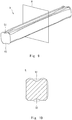
- Fig. 1 is a perspective view showing a schematic configuration of an arm component according to a first embodiment of the present disclosure.
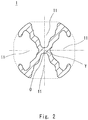
- Fig. 2 is a cross section taken on a plane A in the arm component shown in Fig. 1 .
- An arm component 1 according to the first embodiment is, for example, a rod-shaped suspension arm (e.g., an I-arm).
- the arm component 1 is formed in a roughly cylindrical shape, the shape of the arm component 1 is not limited to the cylindrical shape.
- the arm component 1 may be formed in a polygonal prism shape.
- the arm component 1 has a solid structure, it is not limited to the solid structure.
- the arm component 1 may have a hollow structure.
- the arm component 1 is integrally molded by using, for example, a 3D (three-dimensional) printer.
- the suspension arm is, for example, a component used in a suspension system of an automobile or the like, and is a component extremely important for steering stability and riding comfort. Therefore, it is necessary to appropriately reduce torsional rigidity of the suspension arm so that a torsional deformation occurs in a flexible and satisfactory manner even when a torsional load is imposed on the suspension arm while ensuring a predetermined tensile strength and a compressive strength.
- a slit is formed and hence a stress is concentrated on this slit.
- durability of the suspension arm may be impaired. Therefore, there is a need for an arm component capable of reducing the torsional rigidity and sustaining the durability at the same time.
- At least one underfill part 11 is formed in the arm component 1 so that a central axis O of the arm component 1 coincides with (i.e., aligns with) a load line Y of the arm component 1.
- the central axis O of the arm component 1 is a line that connects centroids (centers of gravity) of cross-sectional shapes, which are shapes on cross-sectional planes perpendicular to the axis of the arm component 1, with one another in the axial direction of the arm component 1.
- the load line Y of the arm component 1 is a line on which a load is imposed in the arm component 1, i.e., a line that a force passes through when a load is imposed on the arm component 1.
- the load line Y of the arm component 1 is a straight line that connects a fixed point at which the arm component 1 is fixed with a load point at which a load is imposed on the arm component 1 in the longitudinal direction of the arm component 1.
- underfill parts 11 By forming underfill parts 11 in the arm component 1, it is possible to optimally reduce torsional rigidity of the arm component 1 while reducing the weight of the arm component 1. Further, by making the central axis O and the load line Y of the arm component 1 coincident with each other (i.e., aligned with each other), the arm component 1 becomes less likely to be buckled (less likely to be bent in an awkward direction). Therefore, it is possible to prevent the stress from being concentrated in the arm component 1. That is, it is possible to reduce the torsional rigidity of the arm component 1 and sustain the durability thereof at the same time.
- the torsional rigidity of the arm component 1 decreases. Conversely, when the length of the underfill parts 11 in the axial direction of the arm component 1 is decreased, the torsional rigidity of the arm component 1 increases. Note that the length of the underfill parts 11 can be increased as long as the underfill parts 11 do not reach collar parts (which will be described later). This is because, for example, when the underfill parts 11 extend to the collar part, a stress tends to be concentrated on a place where the underfill parts 11 intersect (i.e., connect with) the collar part.
- the underfill parts 11 are set (i.e., defined) in the arm component 1 so that the torsional rigidity of the arm component 1 has a predetermined value by which a torsional deformation occurs in the arm component 1 in a flexible and satisfactory manner, and so that the central axis O and the load line Y of the arm component 1 coincide with each other.
- the underfill parts 11 may be formed near the center of the cylindrical arm component 1 so that the cross-sectional shape of the arm component 1 becomes a roughly X-shape.
- the underfill parts 11 may be formed so that their cross-sectional shapes become roughly symmetrical to each other.
- torsional rigidity of the arm component 1 having a hollow structure is defined as 100%
- the torsional rigidity of the arm component 1 can be reduced to approximately 2% (1/50) by forming the underfill parts 11 as shown in Fig. 2
- the underfill parts 11 are formed so that the cross-sectional shape of the arm component 1 becomes a roughly X-shape, while securing the cross-sectional area necessary for the arm component. Further, since the central axis O and the load line Y of the arm component 1 coincide with each other (i.e., are aligned with each other), the arm component 1 has a structure with which the arm component 1 is less likely to be buckled. As a result, it is possible to optimally reduce the torsional rigidity of the arm component 1 so that a torsional deformation occurs in a flexible and satisfactory manner while securing a tensile strength and a compressive strength of the arm component 1.
- an arm component 1 is integrally molded by a 3D (three-dimensional) printer.
- the 3D printer is an apparatus that forms (e.g., molds) a 3D (three-dimensional) arm component 1 by stacking its cross-sectional shapes one another through an adding process by using an additive manufacturing method or the like while using 3D data of the arm component 1 created on a computer as a design blueprint.
- underfill parts 11 are set (i.e., defined) in the arm component 1 so that the torsional rigidity of the formed arm component 1 has a predetermined value and the central axis O and the load line Y of the formed arm component 1 coincide with each other as described above.
- the 3D printer drives its nozzle based on the 3D data of the arm component 1, and thereby discharges (e.g., spews out) a powder of metal, ceramic, nylon, or the like from the nozzle toward an area(s) corresponding to the cross-sectional shape of the arm component 1 and discharges (e.g., spews out) support material toward an area(s) other than the cross-sectional shape of the arm component 1, such an area(s) corresponding to the underfill parts 11.
- the 3D printer drives a laser apparatus so that it applies high-power laser to the area(s) corresponding to the cross-sectional shape of the arm component 1 and thereby forms (e.g., molds) the cross-sectional shape in each layer.
- the 3D printer stacks the cross-sectional shape of each layer and thereby forms (e.g., molds) the 3D arm component 1. Lastly, the 3D printer removes the support material deposited in space inside the arm component 1 as well as the support material deposited around the arm component 1.
- At least one underfill part 11 is formed in the arm component 1 so that the central axis O of the arm component 1 coincides with (i.e., is aligned with) the load line Y of the arm component 1.
- the arm component 1 becomes less likely to be buckled. Therefore, it is possible to prevent the stress from being concentrated in the arm component 1. That is, it is possible to reduce the torsional rigidity of the arm component 1 and sustain the durability thereof at the same time.
- the underfill parts 11 are formed near the center of the cylindrical arm component 1 so that the cross-sectional shape of the arm component 1 becomes a roughly X-shape.
- a second embodiment another form of underfill parts by which desired torsional rigidity of an arm component can be obtained and a central axis of the arm component coincides with a load line thereof is described.
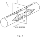
- Fig. 3 shows an example of underfill parts that are formed so that a cross-sectional shape of an arm component becomes a roughly X-shape and a part of its cross-sectional shape is isolated from the other part thereof from the other part thereof.
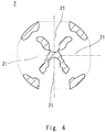
- Fig. 4 is a cross section taken on a plane A in the arm component shown in Fig. 3 .
- underfill parts 21 may be formed near the center of a cylindrical arm component 2 so that the cross-sectional shape of the arm component 2 becomes a roughly X-shape and a part of the cross-sectional shape is isolated from the other part thereof.
- the cross-sectional area of the arm component 2 shown in Fig. 4 is smaller than that of the arm component 1 shown in Fig. 2 because of the aforementioned isolation on the cross section.
- the torsional rigidity of the arm component 2 shown in Fig. 4 is further reduced from that of the arm component 1 shown in Fig. 2 .
- the torsional rigidity of an arm component having a hollow structure is defined as 100%
- the torsional rigidity of the arm component 2 can be reduced to approximately 1% (1/100) by forming the underfill parts 21 as shown in Fig. 3 .
- Fig. 5 shows an example of underfill parts that are formed so that a cross-sectional shape of an arm component becomes a roughly X-shape over the entire length in the axial direction.
- Fig. 6 is a cross section taken on a plane A in the arm component shown in Fig. 5 .
- underfill parts 31 may be formed so that a cross-sectional shape of an arm component 3 becomes a roughly X-shape over the entire length in the axial direction.
- the underfill parts 31 may be formed so that the cross-sectional area of the X-shape at the center of the arm component 3 in the axial direction becomes larger than that of the X-shape at both ends in the axial direction.
- torsional rigidity of an arm component having a hollow structure is defined as 100%
- the torsional rigidity of the arm component 3 can be reduced to approximately 10% (1/10) by forming the underfill parts 31 as shown in Fig. 5 .
- Fig. 7 shows an example of underfill parts that are formed so that a cross-sectional shape of an arm component becomes a roughly annular shape.
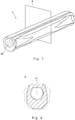
- Fig. 8 is a cross section taken on a plane A in the arm component shown in Fig. 7 .
- Underfill parts 41 of an arm component 4 may be formed so that a cross-sectional shape of the arm component 4 becomes a roughly annular shape. Further, an inner circle of the annular cross-sectional shape may be eccentric to an outer circle thereof.
- torsional rigidity of an arm component having a hollow structure is defined as 100%
- the torsional rigidity of the arm component 4 can be reduced to approximately 5% (1/20) by forming the underfill parts 41 as shown in Fig. 7 .
- Fig. 9 shows an example of underfill parts that are formed so that a cross-sectional shape of an arm component becomes a roughly rectangular (or square) shape.
- Fig. 10 is a cross section taken on a plane A in the arm component shown in Fig. 9 .
- Underfill parts 51 of an arm component 5 may be formed so that a cross-sectional shape of the arm component 5 becomes a roughly rectangular (or square) shape. Further, the underfill parts 51 of the arm component 5 may be formed so that a part of each of the upper and lower sides of the rectangular cross-sectional shape has a concave shape.
- torsional rigidity of an arm component having a hollow structure is defined as 100%, the torsional rigidity of the arm component 5 can be reduced to approximately 2.5% (1/40) by forming the underfill parts 51 as shown in Fig. 9 .
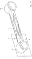
- Fig. 11 is a perspective view of an arm component according to a third embodiment of the present disclosure.
- Fig. 12 is a cross section taken on a plane A in the arm component shown in Fig. 11 .
- a cylindrical collar part 10 is formed at each end of an arm component 1 as shown in Fig. 11 .
- the arm component 1 and both of the collars 10 are integrally molded by using, for example, a 3D printer.
- a hollow part 12 with a hollow formed inside thereof is formed along the axial direction of the arm component 1 at each end of the arm component 1.
- Each of the hollow parts 12 is formed in such a manner that a hollow having a predetermined length is formed along the axial direction of the arm component 1 at the end of the arm component 1.
- a communicating hole 13 that communicates between a space inside the collar part 10 and the hollow part 12 may be formed in a connecting part of the collar part 10 that connects with the end of the arm component 1. It is possible to pull out (i.e., remove) support material deposited inside the hollow part 12 through this communicating hole 13.
- the communicating hole 13 is formed so as to be centered on the central axis O, which connects centroids with one another. Therefore, the communicating hole 13 prevents the stress to be concentrated and thereby improves the durability of the arm component. That is, it is possible to increase the durability of the arm component 1 and reduce the weight thereof. Note that since the part where the end of the arm component 1 connects with the collar part 10 is deviated from the centroid, the strength and robustness of the arm component 1 can be ensured.
- the arm component 1 is applied to (i.e., used as) a suspension arm.
- the application of the arm component 1 is not limited to the suspension arm.
- the arm component 1 may be applied to, for example, a torque rod of an engine or the like. That is, the arm component 1 may be applied to any type of a rod-shaped arm to which a torque is applied (or exerted).
Landscapes
- Engineering & Computer Science (AREA)
- Mechanical Engineering (AREA)
- Vehicle Body Suspensions (AREA)
- Powder Metallurgy (AREA)
- Moulds For Moulding Plastics Or The Like (AREA)
Abstract
Description
- The present disclosure relates to a rod-shaped arm component and its manufacturing method.
- A suspension arm including a rod-shaped arm part and cylindrical collar parts formed at ends of the arm part has been known (see Japanese Unexamined Patent Application Publication No.
2013-032158 - The present inventors have found the following problem. In the aforementioned suspension arm, a stress is concentrated on the slit formed in the arm part. Therefore, durability of the suspension arm could be impaired. Accordingly, there is a need for an arm component capable of reducing the torsional rigidity and sustaining the durability at the same time.
- The present disclosure has been made in order to solve the above-described problem and a main object thereof is to provide an arm component capable of reducing its torsional rigidity and sustaining its durability at the same time, and its manufacturing method.
- A first exemplary aspect to achieve the above-described object is a rod-shaped arm component, in which at least one underfill part is formed so that a central axis of the arm component coincides with a load line of the arm component, the central axis of the arm component being a line connecting centroids of cross-sectional shapes with one another in an axial direction of the arm component, the cross-sectional shapes being shapes on cross-sectional planes perpendicular to an axis of the arm component, the load line of the arm component indicating a line on which a load is imposed in the arm component.
- In this aspect, the underfill part may be formed in the arm component so that torsional rigidity of the arm component has a predetermined value and the central axis of the arm component coincides with the load line of the arm component.
- In this aspect, a cylindrical collar part may be integrally formed at an end of the arm component. A hollow part with a hollow formed inside thereof may be formed along the axial direction of the arm component at the end of the arm component. A communicating hole communicating between a space inside the collar part and the hollow part may be formed in a connecting part of the collar part, the connecting part of the collar part connecting with the end of the arm component. Further, the communicating hole may be formed so as to be centered on the central axis of the arm component.
- In this aspect, the underfill part may be formed so that the cross-sectional shape of the arm component becomes an X-shape.
- Another exemplary aspect to achieve the above-described object may be a method for manufacturing a rod-shaped arm component, in which at least one underfill part is formed in the arm component so that a central axis of the arm component coincides with a load line of the arm component, the central axis of the arm component being a line connecting centroids of cross-sectional shapes with one another in an axial direction of the arm component, the cross-sectional shapes being shapes on cross-sectional planes perpendicular to an axis of the arm component, the load line of the arm component indicating a line on which a load is imposed in the arm component.
- In this aspect, the arm component may be integrally formed by a 3D (three-dimensional) printer.
- According to the present disclosure, it is possible to provide an arm component capable of reducing its torsional rigidity and sustaining its durability at the same time, and its manufacturing method.
- The above and other objects, features and advantages of the present disclosure will become more fully understood from the detailed description given hereinbelow and the accompanying drawings which are given by way of illustration only, and thus are not to be considered as limiting the present disclosure.
-
-
Fig. 1 is a perspective view showing a schematic configuration of an arm component according to a first embodiment of the present disclosure; -
Fig. 2 is a cross section taken on a plane A in the arm component shown inFig. 1 ; -
Fig. 3 shows an example of underfill parts that are formed so that a cross-sectional shape of an arm component becomes a roughly X-shape and a part of its cross-sectional shape is isolated from the other part thereof; -
Fig. 4 is a cross section taken on a plane A in the arm component shown inFig. 3 ; -
Fig. 5 shows an example of underfill parts that are formed so that a cross-sectional shape of an arm component becomes a roughly X-shape over the entire length in the axial direction; -
Fig. 6 is a cross section taken on a plane A in the arm component shown inFig. 5 ; -
Fig. 7 shows an example of underfill parts that are formed so that a cross-sectional shape of an arm component becomes a roughly annular shape; -
Fig. 8 is a cross section taken on a plane A in the arm component shown inFig. 7 ; -
Fig. 9 shows an example of underfill parts that are formed so that a cross-sectional shape of an arm component becomes a roughly rectangular (or square) shape; -
Fig. 10 is a cross section taken on a plane A in the arm component shown inFig. 9 ; -
Fig. 11 is a perspective view of an arm component according to a third embodiment of the present disclosure; and -
Fig. 12 is a cross section taken on a plane A in the arm component shown inFig. 11 . - Embodiments according to the present disclosure will be described hereinafter with reference to the drawings.
Fig. 1 is a perspective view showing a schematic configuration of an arm component according to a first embodiment of the present disclosure.Fig. 2 is a cross section taken on a plane A in the arm component shown inFig. 1 . - An
arm component 1 according to the first embodiment is, for example, a rod-shaped suspension arm (e.g., an I-arm). Although thearm component 1 is formed in a roughly cylindrical shape, the shape of thearm component 1 is not limited to the cylindrical shape. For example, thearm component 1 may be formed in a polygonal prism shape. Although thearm component 1 has a solid structure, it is not limited to the solid structure. For example, thearm component 1 may have a hollow structure. Thearm component 1 is integrally molded by using, for example, a 3D (three-dimensional) printer. - The suspension arm is, for example, a component used in a suspension system of an automobile or the like, and is a component extremely important for steering stability and riding comfort. Therefore, it is necessary to appropriately reduce torsional rigidity of the suspension arm so that a torsional deformation occurs in a flexible and satisfactory manner even when a torsional load is imposed on the suspension arm while ensuring a predetermined tensile strength and a compressive strength.
- In a related-art suspension arm, for example, a slit is formed and hence a stress is concentrated on this slit. As a result, durability of the suspension arm may be impaired. Therefore, there is a need for an arm component capable of reducing the torsional rigidity and sustaining the durability at the same time.
- To that end, in the first embodiment, at least one
underfill part 11 is formed in thearm component 1 so that a central axis O of thearm component 1 coincides with (i.e., aligns with) a load line Y of thearm component 1. The central axis O of thearm component 1 is a line that connects centroids (centers of gravity) of cross-sectional shapes, which are shapes on cross-sectional planes perpendicular to the axis of thearm component 1, with one another in the axial direction of thearm component 1. - The load line Y of the
arm component 1 is a line on which a load is imposed in thearm component 1, i.e., a line that a force passes through when a load is imposed on thearm component 1. For example, the load line Y of thearm component 1 is a straight line that connects a fixed point at which thearm component 1 is fixed with a load point at which a load is imposed on thearm component 1 in the longitudinal direction of thearm component 1. - By forming
underfill parts 11 in thearm component 1, it is possible to optimally reduce torsional rigidity of thearm component 1 while reducing the weight of thearm component 1. Further, by making the central axis O and the load line Y of thearm component 1 coincident with each other (i.e., aligned with each other), thearm component 1 becomes less likely to be buckled (less likely to be bent in an awkward direction). Therefore, it is possible to prevent the stress from being concentrated in thearm component 1. That is, it is possible to reduce the torsional rigidity of thearm component 1 and sustain the durability thereof at the same time. - Next, a method for setting (i.e., defining)
underfill parts 11 to optimally reduce torsional rigidity in the first embodiment is described in detail. Under the assumption that theunderfill parts 11 are formed in thearm component 1 so that the central axis O and the load line Y of thearm component 1 coincide with each other as described above, shapes of theunderfill parts 11 are determined while taking the below-described matters into consideration. - For example, when the size of the cross-sectional shape of the
underfill parts 11 is increased and the size of the cross-sectional shape of thearm component 1 is decreased, torsional rigidity of thearm component 1 decreases. Conversely, when the size of the cross-sectional shape of theunderfill parts 11 is decreased and the size of the cross-sectional shape of thearm component 1 is increased, the torsional rigidity of thearm component 1 increases. - When the length of the
underfill parts 11 in the axial direction of thearm component 1 is increased, the torsional rigidity of thearm component 1 decreases. Conversely, when the length of theunderfill parts 11 in the axial direction of thearm component 1 is decreased, the torsional rigidity of thearm component 1 increases. Note that the length of theunderfill parts 11 can be increased as long as theunderfill parts 11 do not reach collar parts (which will be described later). This is because, for example, when theunderfill parts 11 extend to the collar part, a stress tends to be concentrated on a place where theunderfill parts 11 intersect (i.e., connect with) the collar part. - In view of the above-described matters, the
underfill parts 11 are set (i.e., defined) in thearm component 1 so that the torsional rigidity of thearm component 1 has a predetermined value by which a torsional deformation occurs in thearm component 1 in a flexible and satisfactory manner, and so that the central axis O and the load line Y of thearm component 1 coincide with each other. - For example, as shown in
Fig. 2 , theunderfill parts 11 may be formed near the center of thecylindrical arm component 1 so that the cross-sectional shape of thearm component 1 becomes a roughly X-shape. Theunderfill parts 11 may be formed so that their cross-sectional shapes become roughly symmetrical to each other. For example, when torsional rigidity of thearm component 1 having a hollow structure is defined as 100%, the torsional rigidity of thearm component 1 can be reduced to approximately 2% (1/50) by forming theunderfill parts 11 as shown inFig. 2 - As shown in
Fig. 2 , theunderfill parts 11 are formed so that the cross-sectional shape of thearm component 1 becomes a roughly X-shape, while securing the cross-sectional area necessary for the arm component. Further, since the central axis O and the load line Y of thearm component 1 coincide with each other (i.e., are aligned with each other), thearm component 1 has a structure with which thearm component 1 is less likely to be buckled. As a result, it is possible to optimally reduce the torsional rigidity of thearm component 1 so that a torsional deformation occurs in a flexible and satisfactory manner while securing a tensile strength and a compressive strength of thearm component 1. - Next, a method for manufacturing an arm component according to the first embodiment is described.
- For example, an
arm component 1 is integrally molded by a 3D (three-dimensional) printer. The 3D printer is an apparatus that forms (e.g., molds) a 3D (three-dimensional)arm component 1 by stacking its cross-sectional shapes one another through an adding process by using an additive manufacturing method or the like while using 3D data of thearm component 1 created on a computer as a design blueprint. In the 3D data of thearm component 1,underfill parts 11 are set (i.e., defined) in thearm component 1 so that the torsional rigidity of the formedarm component 1 has a predetermined value and the central axis O and the load line Y of the formedarm component 1 coincide with each other as described above. - The 3D printer drives its nozzle based on the 3D data of the
arm component 1, and thereby discharges (e.g., spews out) a powder of metal, ceramic, nylon, or the like from the nozzle toward an area(s) corresponding to the cross-sectional shape of thearm component 1 and discharges (e.g., spews out) support material toward an area(s) other than the cross-sectional shape of thearm component 1, such an area(s) corresponding to theunderfill parts 11. Then, the 3D printer drives a laser apparatus so that it applies high-power laser to the area(s) corresponding to the cross-sectional shape of thearm component 1 and thereby forms (e.g., molds) the cross-sectional shape in each layer. By repeating the above-described process, the 3D printer stacks the cross-sectional shape of each layer and thereby forms (e.g., molds) the3D arm component 1. Lastly, the 3D printer removes the support material deposited in space inside thearm component 1 as well as the support material deposited around thearm component 1. - As described above, in the
arm component 1 according to the first embodiment, at least oneunderfill part 11 is formed in thearm component 1 so that the central axis O of thearm component 1 coincides with (i.e., is aligned with) the load line Y of thearm component 1. By formingunderfill parts 11 in thearm component 1, it is possible to optimally reduce torsional rigidity of thearm component 1 while reducing the weight of thearm component 1. Further, by making the central axis O and the load line Y of thearm component 1 coincident with each other, thearm component 1 becomes less likely to be buckled. Therefore, it is possible to prevent the stress from being concentrated in thearm component 1. That is, it is possible to reduce the torsional rigidity of thearm component 1 and sustain the durability thereof at the same time. - In the above-described first embodiment, the
underfill parts 11 are formed near the center of thecylindrical arm component 1 so that the cross-sectional shape of thearm component 1 becomes a roughly X-shape. In a second embodiment, another form of underfill parts by which desired torsional rigidity of an arm component can be obtained and a central axis of the arm component coincides with a load line thereof is described. -
Fig. 3 shows an example of underfill parts that are formed so that a cross-sectional shape of an arm component becomes a roughly X-shape and a part of its cross-sectional shape is isolated from the other part thereof from the other part thereof.Fig. 4 is a cross section taken on a plane A in the arm component shown inFig. 3 . As shown inFig. 3 ,underfill parts 21 may be formed near the center of acylindrical arm component 2 so that the cross-sectional shape of thearm component 2 becomes a roughly X-shape and a part of the cross-sectional shape is isolated from the other part thereof. - The cross-sectional area of the
arm component 2 shown inFig. 4 is smaller than that of thearm component 1 shown inFig. 2 because of the aforementioned isolation on the cross section. As a result, the torsional rigidity of thearm component 2 shown inFig. 4 is further reduced from that of thearm component 1 shown inFig. 2 . When torsional rigidity of an arm component having a hollow structure is defined as 100%, the torsional rigidity of thearm component 2 can be reduced to approximately 1% (1/100) by forming theunderfill parts 21 as shown inFig. 3 . -
Fig. 5 shows an example of underfill parts that are formed so that a cross-sectional shape of an arm component becomes a roughly X-shape over the entire length in the axial direction.Fig. 6 is a cross section taken on a plane A in the arm component shown inFig. 5 . As shown inFig. 5 ,underfill parts 31 may be formed so that a cross-sectional shape of anarm component 3 becomes a roughly X-shape over the entire length in the axial direction. - The
underfill parts 31 may be formed so that the cross-sectional area of the X-shape at the center of thearm component 3 in the axial direction becomes larger than that of the X-shape at both ends in the axial direction. When torsional rigidity of an arm component having a hollow structure is defined as 100%, the torsional rigidity of thearm component 3 can be reduced to approximately 10% (1/10) by forming theunderfill parts 31 as shown inFig. 5 . -
Fig. 7 shows an example of underfill parts that are formed so that a cross-sectional shape of an arm component becomes a roughly annular shape.Fig. 8 is a cross section taken on a plane A in the arm component shown inFig. 7 .Underfill parts 41 of anarm component 4 may be formed so that a cross-sectional shape of thearm component 4 becomes a roughly annular shape. Further, an inner circle of the annular cross-sectional shape may be eccentric to an outer circle thereof. When torsional rigidity of an arm component having a hollow structure is defined as 100%, the torsional rigidity of thearm component 4 can be reduced to approximately 5% (1/20) by forming theunderfill parts 41 as shown inFig. 7 . -
Fig. 9 shows an example of underfill parts that are formed so that a cross-sectional shape of an arm component becomes a roughly rectangular (or square) shape.Fig. 10 is a cross section taken on a plane A in the arm component shown inFig. 9 .Underfill parts 51 of anarm component 5 may be formed so that a cross-sectional shape of thearm component 5 becomes a roughly rectangular (or square) shape. Further, theunderfill parts 51 of thearm component 5 may be formed so that a part of each of the upper and lower sides of the rectangular cross-sectional shape has a concave shape. When torsional rigidity of an arm component having a hollow structure is defined as 100%, the torsional rigidity of thearm component 5 can be reduced to approximately 2.5% (1/40) by forming theunderfill parts 51 as shown inFig. 9 . -
Fig. 11 is a perspective view of an arm component according to a third embodiment of the present disclosure.Fig. 12 is a cross section taken on a plane A in the arm component shown inFig. 11 . For example, acylindrical collar part 10 is formed at each end of anarm component 1 as shown inFig. 11 . Thearm component 1 and both of thecollars 10 are integrally molded by using, for example, a 3D printer. - A
hollow part 12 with a hollow formed inside thereof is formed along the axial direction of thearm component 1 at each end of thearm component 1. Each of thehollow parts 12 is formed in such a manner that a hollow having a predetermined length is formed along the axial direction of thearm component 1 at the end of thearm component 1. By making the end of thearm component 1 hollow as described above, it is possible to reduce the weight of thearm component 1 and reduce the torsional rigidity of thearm component 1. - A communicating
hole 13 that communicates between a space inside thecollar part 10 and thehollow part 12 may be formed in a connecting part of thecollar part 10 that connects with the end of thearm component 1. It is possible to pull out (i.e., remove) support material deposited inside thehollow part 12 through this communicatinghole 13. - Further, the communicating
hole 13 is formed so as to be centered on the central axis O, which connects centroids with one another. Therefore, the communicatinghole 13 prevents the stress to be concentrated and thereby improves the durability of the arm component. That is, it is possible to increase the durability of thearm component 1 and reduce the weight thereof. Note that since the part where the end of thearm component 1 connects with thecollar part 10 is deviated from the centroid, the strength and robustness of thearm component 1 can be ensured. - In the third embodiment, the same components/structures as those of the first embodiment are indicated by the same symbols as those of the first embodiment and their detailed descriptions are omitted.
- Several embodiments according to the present disclosure have been explained above. However, these embodiments are shown as examples but are not shown to limit the scope of the disclosure. These novel embodiments can be implemented in various forms. Further, their components/structures may be omitted, replaced, or modified without departing from the scope and spirit of the disclosure. These embodiments and their modifications are included in the scope and the spirit of the disclosure, and included in the scope equivalent to the disclosure specified in the claims.
- In the above-described embodiments, the
arm component 1 is applied to (i.e., used as) a suspension arm. However, the application of thearm component 1 is not limited to the suspension arm. Thearm component 1 may be applied to, for example, a torque rod of an engine or the like. That is, thearm component 1 may be applied to any type of a rod-shaped arm to which a torque is applied (or exerted). - From the disclosure thus described, it will be obvious that the embodiments of the disclosure may be varied in many ways. Such variations are not to be regarded as a departure from the spirit and scope of the disclosure, and all such modifications as would be obvious to one skilled in the art are intended for inclusion within the scope of the following claims.
Claims (6)
- A rod-shaped arm component (1), wherein at least one underfill part (11) is formed so that a central axis (O) of the arm component (1) coincides with a load line (Y) of the arm component (1), the central axis (O) of the arm component (1) being a line connecting centroids of cross-sectional shapes with one another in an axial direction of the arm component (1), the cross-sectional shapes being shapes on cross-sectional planes perpendicular to an axis of the arm component (1), the load line (Y) of the arm component (1) indicating a line on which a load is imposed in the arm component (1).
- The arm component (1) according to Claim 1, wherein the underfill part (11) is formed in the arm component (1) so that torsional rigidity of the arm component (1) has a predetermined value and the central axis (O) of the arm component (1) coincides with the load line (Y) of the arm component (1).
- The arm component (1) according to Claim 1 or 2, wherein
a cylindrical collar part (10) is integrally formed at an end of the arm component (1),
a hollow part (12) with a hollow formed inside thereof is formed along the axial direction of the arm component (1) at the end of the arm component (1),
a communicating hole (13) communicating between a space inside the collar part (10) and the hollow part (12) is formed in a connecting part of the collar part (10), the connecting part of the collar part (10) connecting with the end of the arm component (1), and
the communicating hole (13) is formed so as to be centered on the central axis (O) of the arm component (1). - The arm component (1) according to any one of Claims 1 to 3, wherein the underfill part (11) is formed so that the cross-sectional shape of the arm component (1) becomes an X-shape.
- A method for manufacturing a rod-shaped arm component (1), wherein at least one underfill part (11) is formed in the arm component (1) so that a central axis (O) of the arm component (1) coincides with a load line (Y) of the arm component (1), the central axis (O) of the arm component (1) being a line connecting centroids of cross-sectional shapes with one another in an axial direction of the arm component (1), the cross-sectional shapes being shapes on cross-sectional planes perpendicular to an axis of the arm component (1), the load line (Y) of the arm component (1) indicating a line on which a load is imposed in the arm component (1).
- The method for manufacturing a rod-shaped arm component (1) according to Claim 5, wherein the arm component (1) is integrally formed by a 3D (three-dimensional) printer.
Applications Claiming Priority (1)
| Application Number | Priority Date | Filing Date | Title |
|---|---|---|---|
| JP2018021804A JP7102761B2 (en) | 2018-02-09 | 2018-02-09 | Manufacturing method of arm member |
Publications (2)
| Publication Number | Publication Date |
|---|---|
| EP3524450A1 true EP3524450A1 (en) | 2019-08-14 |
| EP3524450B1 EP3524450B1 (en) | 2022-10-05 |
Family
ID=65010628
Family Applications (1)
| Application Number | Title | Priority Date | Filing Date |
|---|---|---|---|
| EP19150792.0A Active EP3524450B1 (en) | 2018-02-09 | 2019-01-08 | Arm component and manufacturing method therefor |
Country Status (4)
| Country | Link |
|---|---|
| US (1) | US11021028B2 (en) |
| EP (1) | EP3524450B1 (en) |
| JP (1) | JP7102761B2 (en) |
| CN (1) | CN110126564B (en) |
Cited By (1)
| Publication number | Priority date | Publication date | Assignee | Title |
|---|---|---|---|---|
| EP4066966A1 (en) * | 2021-03-31 | 2022-10-05 | Renault s.a.s | Suspension rod obtained by an additive manufacturing technique |
Families Citing this family (1)
| Publication number | Priority date | Publication date | Assignee | Title |
|---|---|---|---|---|
| CN114454678B (en) * | 2022-01-24 | 2023-12-29 | 天润工业技术股份有限公司 | A cast thrust rod for automobiles |
Citations (5)
| Publication number | Priority date | Publication date | Assignee | Title |
|---|---|---|---|---|
| JP2003034112A (en) * | 2001-07-19 | 2003-02-04 | Bridgestone Corp | Method of manufacturing guide member for automotive suspension device |
| US20120001397A1 (en) * | 2010-07-01 | 2012-01-05 | The Pullman Company | Extruded torque rods |
| JP2013032158A (en) | 2012-10-09 | 2013-02-14 | Toyota Motor Corp | I-shaped suspension arm for vehicle |
| DE202017100165U1 (en) * | 2016-12-02 | 2017-03-20 | Ford Global Technologies, Llc | Wishbone for a suspension of a vehicle |
| WO2017099212A1 (en) * | 2015-12-09 | 2017-06-15 | 新日鐵住金株式会社 | Control arm |
Family Cites Families (24)
| Publication number | Priority date | Publication date | Assignee | Title |
|---|---|---|---|---|
| US1898100A (en) * | 1929-12-09 | 1933-02-21 | O & S Bearing Company | Permanent connecting unit and method of forming same |
| DE4330103C2 (en) * | 1992-09-22 | 1998-09-10 | Suzuki Motor Co | Suspension arm for the suspension of a motor vehicle |
| JPH07242110A (en) * | 1994-03-03 | 1995-09-19 | Hitachi Metals Ltd | Suspension part |
| JPH10264626A (en) * | 1997-03-26 | 1998-10-06 | Unie Press Kk | Manufacture of suspension parts |
| DE19911121A1 (en) * | 1998-03-13 | 1999-09-16 | Tokai Rubber Ind Ltd | Connecting arm for vehicle suspension |
| JP2001214920A (en) | 2000-02-03 | 2001-08-10 | Showa Denko Kk | Member for arm |
| BR0100427A (en) * | 2001-01-24 | 2004-06-22 | Dana Industrial Ltda | Rod construction |
| JP2002048115A (en) * | 2001-06-08 | 2002-02-15 | Tokai Rubber Ind Ltd | Bushing mounting member |
| DE50212379D1 (en) * | 2001-12-05 | 2008-07-31 | Benteler Automobiltechnik Gmbh | Method for producing a handlebar and handlebar |
| US20050281610A1 (en) * | 2004-06-04 | 2005-12-22 | Maclean Barry L | Composite link |
| CN101484266B (en) * | 2006-07-19 | 2012-05-02 | 日本轻金属株式会社 | Friction welded part, suspension rod having the friction welded part, and joining method |
| US20080235946A1 (en) * | 2007-03-29 | 2008-10-02 | Yamashita Rubber Kabushiki Kaisha | Link rod manufacturing method |
| JP2009184460A (en) | 2008-02-05 | 2009-08-20 | Showa Denko Kk | Vehicular link component |
| JP4933476B2 (en) * | 2008-04-18 | 2012-05-16 | 日本発條株式会社 | Ball joint |
| CN100575701C (en) | 2008-04-30 | 2009-12-30 | 林波 | Metering pumps and their drives |
| DE102009031289B4 (en) * | 2009-06-30 | 2020-03-05 | THK RHYTHM AUTOMOTIVE GmbH | Stabilizer strut |
| MX364190B (en) * | 2012-06-08 | 2019-04-16 | Nippon Steel & Sumitomo Metal Corp | Coupling structure, coupling member having coupling structure, and method for producing coupling member having coupling structure. |
| JP6131787B2 (en) | 2013-09-03 | 2017-05-24 | トヨタ自動車株式会社 | Vehicle suspension arm |
| US9909613B2 (en) | 2014-04-15 | 2018-03-06 | Roller Bearing Company Of America, Inc. | Compression rod having a buckling initiating feature |
| DE102014011859A1 (en) * | 2014-08-09 | 2016-02-11 | Man Truck & Bus Ag | Axle suspension for steered rigid axles in vehicles, in particular in commercial vehicles |
| DE102014011860A1 (en) * | 2014-08-09 | 2016-02-11 | Man Truck & Bus Ag | Four-point link |
| NO341338B1 (en) * | 2015-08-28 | 2017-10-16 | Raufoss Tech As | Control arm |
| JP6464996B2 (en) * | 2015-11-11 | 2019-02-06 | トヨタ自動車株式会社 | Control device for 3D printer device |
| DE102016224023A1 (en) * | 2016-12-02 | 2018-06-07 | Ford Global Technologies, Llc | Control arm for a wheel suspension of a vehicle and method for its production |
-
2018
- 2018-02-09 JP JP2018021804A patent/JP7102761B2/en active Active
-
2019
- 2019-01-07 US US16/240,823 patent/US11021028B2/en active Active
- 2019-01-08 EP EP19150792.0A patent/EP3524450B1/en active Active
- 2019-01-31 CN CN201910097386.5A patent/CN110126564B/en not_active Expired - Fee Related
Patent Citations (5)
| Publication number | Priority date | Publication date | Assignee | Title |
|---|---|---|---|---|
| JP2003034112A (en) * | 2001-07-19 | 2003-02-04 | Bridgestone Corp | Method of manufacturing guide member for automotive suspension device |
| US20120001397A1 (en) * | 2010-07-01 | 2012-01-05 | The Pullman Company | Extruded torque rods |
| JP2013032158A (en) | 2012-10-09 | 2013-02-14 | Toyota Motor Corp | I-shaped suspension arm for vehicle |
| WO2017099212A1 (en) * | 2015-12-09 | 2017-06-15 | 新日鐵住金株式会社 | Control arm |
| DE202017100165U1 (en) * | 2016-12-02 | 2017-03-20 | Ford Global Technologies, Llc | Wishbone for a suspension of a vehicle |
Cited By (2)
| Publication number | Priority date | Publication date | Assignee | Title |
|---|---|---|---|---|
| EP4066966A1 (en) * | 2021-03-31 | 2022-10-05 | Renault s.a.s | Suspension rod obtained by an additive manufacturing technique |
| FR3121390A1 (en) * | 2021-03-31 | 2022-10-07 | Renault S.A.S. | SUSPENSION LINK OBTAINED BY AN ADDITIVE MANUFACTURING TECHNIQUE |
Also Published As
| Publication number | Publication date |
|---|---|
| CN110126564A (en) | 2019-08-16 |
| EP3524450B1 (en) | 2022-10-05 |
| CN110126564B (en) | 2022-10-18 |
| US20190248198A1 (en) | 2019-08-15 |
| JP2019137206A (en) | 2019-08-22 |
| JP7102761B2 (en) | 2022-07-20 |
| US11021028B2 (en) | 2021-06-01 |
Similar Documents
| Publication | Publication Date | Title |
|---|---|---|
| US11021028B2 (en) | Arm component and manufacturing method therefor | |
| CN107405949B (en) | Wheel for vehicle | |
| CN112993457B (en) | End stabilizer for high-voltage battery structural part | |
| US6265810B1 (en) | Piezoelectric support device | |
| EP3007923A1 (en) | Fuel tank | |
| DE102020007681B3 (en) | Bearing, outer sleeve and method of making a bearing | |
| JP4637715B2 (en) | Method for manufacturing support structure for vehicle | |
| CN106042818A (en) | Bracket | |
| US20190248199A1 (en) | Suspension arm and manufacturing method therefor | |
| EP3881949A1 (en) | Bead forming method and structure member | |
| EP2851574A1 (en) | Perforated collapsible spacer | |
| CN112298621A (en) | A separation shell of a space vehicle separation device | |
| CN106958655B (en) | Piston pin and method for manufacturing piston pin | |
| CN107043071B (en) | Expansion joint with variable extension assembly edge | |
| EP3742006A1 (en) | Fused alignment pin | |
| CN219806755U (en) | Connection structure and vehicle | |
| EP3875799A1 (en) | Silent block bushing | |
| KR101794846B1 (en) | Mounting structure of bush-pipe | |
| JP5609322B2 (en) | Method for manufacturing tube member | |
| CN211617353U (en) | Spring support mounting auxiliary seat and vehicle with same | |
| EP4477938A1 (en) | Scissor structure | |
| CN111201096B (en) | Rack bar manufacturing method and rack bar | |
| DE102018005371A1 (en) | Bullet casing and manufacturing process | |
| US20120199235A1 (en) | Dielectric structure that withstands compression | |
| CN210502580U (en) | Safe and reliable automobile bumper |
Legal Events
| Date | Code | Title | Description |
|---|---|---|---|
| PUAI | Public reference made under article 153(3) epc to a published international application that has entered the european phase |
Free format text: ORIGINAL CODE: 0009012 |
|
| STAA | Information on the status of an ep patent application or granted ep patent |
Free format text: STATUS: REQUEST FOR EXAMINATION WAS MADE |
|
| 17P | Request for examination filed |
Effective date: 20190108 |
|
| AK | Designated contracting states |
Kind code of ref document: A1 Designated state(s): AL AT BE BG CH CY CZ DE DK EE ES FI FR GB GR HR HU IE IS IT LI LT LU LV MC MK MT NL NO PL PT RO RS SE SI SK SM TR |
|
| AX | Request for extension of the european patent |
Extension state: BA ME |
|
| STAA | Information on the status of an ep patent application or granted ep patent |
Free format text: STATUS: EXAMINATION IS IN PROGRESS |
|
| 17Q | First examination report despatched |
Effective date: 20210120 |
|
| GRAP | Despatch of communication of intention to grant a patent |
Free format text: ORIGINAL CODE: EPIDOSNIGR1 |
|
| STAA | Information on the status of an ep patent application or granted ep patent |
Free format text: STATUS: GRANT OF PATENT IS INTENDED |
|
| INTG | Intention to grant announced |
Effective date: 20220715 |
|
| GRAS | Grant fee paid |
Free format text: ORIGINAL CODE: EPIDOSNIGR3 |
|
| GRAA | (expected) grant |
Free format text: ORIGINAL CODE: 0009210 |
|
| STAA | Information on the status of an ep patent application or granted ep patent |
Free format text: STATUS: THE PATENT HAS BEEN GRANTED |
|
| AK | Designated contracting states |
Kind code of ref document: B1 Designated state(s): AL AT BE BG CH CY CZ DE DK EE ES FI FR GB GR HR HU IE IS IT LI LT LU LV MC MK MT NL NO PL PT RO RS SE SI SK SM TR |
|
| REG | Reference to a national code |
Ref country code: GB Ref legal event code: FG4D |
|
| REG | Reference to a national code |
Ref country code: CH Ref legal event code: EP |
|
| REG | Reference to a national code |
Ref country code: AT Ref legal event code: REF Ref document number: 1522539 Country of ref document: AT Kind code of ref document: T Effective date: 20221015 |
|
| REG | Reference to a national code |
Ref country code: IE Ref legal event code: FG4D |
|
| REG | Reference to a national code |
Ref country code: DE Ref legal event code: R096 Ref document number: 602019020178 Country of ref document: DE |
|
| REG | Reference to a national code |
Ref country code: LT Ref legal event code: MG9D |
|
| PGFP | Annual fee paid to national office [announced via postgrant information from national office to epo] |
Ref country code: GB Payment date: 20221201 Year of fee payment: 5 Ref country code: FR Payment date: 20221208 Year of fee payment: 5 |
|
| REG | Reference to a national code |
Ref country code: NL Ref legal event code: MP Effective date: 20221005 |
|
| REG | Reference to a national code |
Ref country code: AT Ref legal event code: MK05 Ref document number: 1522539 Country of ref document: AT Kind code of ref document: T Effective date: 20221005 |
|
| PG25 | Lapsed in a contracting state [announced via postgrant information from national office to epo] |
Ref country code: NL Free format text: LAPSE BECAUSE OF FAILURE TO SUBMIT A TRANSLATION OF THE DESCRIPTION OR TO PAY THE FEE WITHIN THE PRESCRIBED TIME-LIMIT Effective date: 20221005 |
|
| PG25 | Lapsed in a contracting state [announced via postgrant information from national office to epo] |
Ref country code: SE Free format text: LAPSE BECAUSE OF FAILURE TO SUBMIT A TRANSLATION OF THE DESCRIPTION OR TO PAY THE FEE WITHIN THE PRESCRIBED TIME-LIMIT Effective date: 20221005 Ref country code: PT Free format text: LAPSE BECAUSE OF FAILURE TO SUBMIT A TRANSLATION OF THE DESCRIPTION OR TO PAY THE FEE WITHIN THE PRESCRIBED TIME-LIMIT Effective date: 20230206 Ref country code: NO Free format text: LAPSE BECAUSE OF FAILURE TO SUBMIT A TRANSLATION OF THE DESCRIPTION OR TO PAY THE FEE WITHIN THE PRESCRIBED TIME-LIMIT Effective date: 20230105 Ref country code: LT Free format text: LAPSE BECAUSE OF FAILURE TO SUBMIT A TRANSLATION OF THE DESCRIPTION OR TO PAY THE FEE WITHIN THE PRESCRIBED TIME-LIMIT Effective date: 20221005 Ref country code: FI Free format text: LAPSE BECAUSE OF FAILURE TO SUBMIT A TRANSLATION OF THE DESCRIPTION OR TO PAY THE FEE WITHIN THE PRESCRIBED TIME-LIMIT Effective date: 20221005 Ref country code: ES Free format text: LAPSE BECAUSE OF FAILURE TO SUBMIT A TRANSLATION OF THE DESCRIPTION OR TO PAY THE FEE WITHIN THE PRESCRIBED TIME-LIMIT Effective date: 20221005 Ref country code: AT Free format text: LAPSE BECAUSE OF FAILURE TO SUBMIT A TRANSLATION OF THE DESCRIPTION OR TO PAY THE FEE WITHIN THE PRESCRIBED TIME-LIMIT Effective date: 20221005 |
|
| PG25 | Lapsed in a contracting state [announced via postgrant information from national office to epo] |
Ref country code: RS Free format text: LAPSE BECAUSE OF FAILURE TO SUBMIT A TRANSLATION OF THE DESCRIPTION OR TO PAY THE FEE WITHIN THE PRESCRIBED TIME-LIMIT Effective date: 20221005 Ref country code: PL Free format text: LAPSE BECAUSE OF FAILURE TO SUBMIT A TRANSLATION OF THE DESCRIPTION OR TO PAY THE FEE WITHIN THE PRESCRIBED TIME-LIMIT Effective date: 20221005 Ref country code: LV Free format text: LAPSE BECAUSE OF FAILURE TO SUBMIT A TRANSLATION OF THE DESCRIPTION OR TO PAY THE FEE WITHIN THE PRESCRIBED TIME-LIMIT Effective date: 20221005 Ref country code: IS Free format text: LAPSE BECAUSE OF FAILURE TO SUBMIT A TRANSLATION OF THE DESCRIPTION OR TO PAY THE FEE WITHIN THE PRESCRIBED TIME-LIMIT Effective date: 20230205 Ref country code: HR Free format text: LAPSE BECAUSE OF FAILURE TO SUBMIT A TRANSLATION OF THE DESCRIPTION OR TO PAY THE FEE WITHIN THE PRESCRIBED TIME-LIMIT Effective date: 20221005 Ref country code: GR Free format text: LAPSE BECAUSE OF FAILURE TO SUBMIT A TRANSLATION OF THE DESCRIPTION OR TO PAY THE FEE WITHIN THE PRESCRIBED TIME-LIMIT Effective date: 20230106 |
|
| PGFP | Annual fee paid to national office [announced via postgrant information from national office to epo] |
Ref country code: DE Payment date: 20221130 Year of fee payment: 5 |
|
| P01 | Opt-out of the competence of the unified patent court (upc) registered |
Effective date: 20230427 |
|
| REG | Reference to a national code |
Ref country code: DE Ref legal event code: R084 Ref document number: 602019020178 Country of ref document: DE |
|
| REG | Reference to a national code |
Ref country code: DE Ref legal event code: R097 Ref document number: 602019020178 Country of ref document: DE |
|
| PG25 | Lapsed in a contracting state [announced via postgrant information from national office to epo] |
Ref country code: SM Free format text: LAPSE BECAUSE OF FAILURE TO SUBMIT A TRANSLATION OF THE DESCRIPTION OR TO PAY THE FEE WITHIN THE PRESCRIBED TIME-LIMIT Effective date: 20221005 Ref country code: RO Free format text: LAPSE BECAUSE OF FAILURE TO SUBMIT A TRANSLATION OF THE DESCRIPTION OR TO PAY THE FEE WITHIN THE PRESCRIBED TIME-LIMIT Effective date: 20221005 Ref country code: EE Free format text: LAPSE BECAUSE OF FAILURE TO SUBMIT A TRANSLATION OF THE DESCRIPTION OR TO PAY THE FEE WITHIN THE PRESCRIBED TIME-LIMIT Effective date: 20221005 Ref country code: DK Free format text: LAPSE BECAUSE OF FAILURE TO SUBMIT A TRANSLATION OF THE DESCRIPTION OR TO PAY THE FEE WITHIN THE PRESCRIBED TIME-LIMIT Effective date: 20221005 Ref country code: CZ Free format text: LAPSE BECAUSE OF FAILURE TO SUBMIT A TRANSLATION OF THE DESCRIPTION OR TO PAY THE FEE WITHIN THE PRESCRIBED TIME-LIMIT Effective date: 20221005 |
|
| PLBE | No opposition filed within time limit |
Free format text: ORIGINAL CODE: 0009261 |
|
| STAA | Information on the status of an ep patent application or granted ep patent |
Free format text: STATUS: NO OPPOSITION FILED WITHIN TIME LIMIT |
|
| PG25 | Lapsed in a contracting state [announced via postgrant information from national office to epo] |
Ref country code: SK Free format text: LAPSE BECAUSE OF FAILURE TO SUBMIT A TRANSLATION OF THE DESCRIPTION OR TO PAY THE FEE WITHIN THE PRESCRIBED TIME-LIMIT Effective date: 20221005 Ref country code: AL Free format text: LAPSE BECAUSE OF FAILURE TO SUBMIT A TRANSLATION OF THE DESCRIPTION OR TO PAY THE FEE WITHIN THE PRESCRIBED TIME-LIMIT Effective date: 20221005 |
|
| REG | Reference to a national code |
Ref country code: CH Ref legal event code: PL |
|
| REG | Reference to a national code |
Ref country code: GB Ref legal event code: 746 Effective date: 20230816 |
|
| 26N | No opposition filed |
Effective date: 20230706 |
|
| PG25 | Lapsed in a contracting state [announced via postgrant information from national office to epo] |
Ref country code: LU Free format text: LAPSE BECAUSE OF NON-PAYMENT OF DUE FEES Effective date: 20230108 |
|
| REG | Reference to a national code |
Ref country code: BE Ref legal event code: MM Effective date: 20230131 |
|
| PG25 | Lapsed in a contracting state [announced via postgrant information from national office to epo] |
Ref country code: LI Free format text: LAPSE BECAUSE OF NON-PAYMENT OF DUE FEES Effective date: 20230131 Ref country code: CH Free format text: LAPSE BECAUSE OF NON-PAYMENT OF DUE FEES Effective date: 20230131 |
|
| PG25 | Lapsed in a contracting state [announced via postgrant information from national office to epo] |
Ref country code: SI Free format text: LAPSE BECAUSE OF FAILURE TO SUBMIT A TRANSLATION OF THE DESCRIPTION OR TO PAY THE FEE WITHIN THE PRESCRIBED TIME-LIMIT Effective date: 20221005 Ref country code: BE Free format text: LAPSE BECAUSE OF NON-PAYMENT OF DUE FEES Effective date: 20230131 |
|
| PG25 | Lapsed in a contracting state [announced via postgrant information from national office to epo] |
Ref country code: IE Free format text: LAPSE BECAUSE OF NON-PAYMENT OF DUE FEES Effective date: 20230108 |
|
| PG25 | Lapsed in a contracting state [announced via postgrant information from national office to epo] |
Ref country code: IT Free format text: LAPSE BECAUSE OF FAILURE TO SUBMIT A TRANSLATION OF THE DESCRIPTION OR TO PAY THE FEE WITHIN THE PRESCRIBED TIME-LIMIT Effective date: 20221005 |
|
| PG25 | Lapsed in a contracting state [announced via postgrant information from national office to epo] |
Ref country code: MC Free format text: LAPSE BECAUSE OF FAILURE TO SUBMIT A TRANSLATION OF THE DESCRIPTION OR TO PAY THE FEE WITHIN THE PRESCRIBED TIME-LIMIT Effective date: 20221005 |
|
| PG25 | Lapsed in a contracting state [announced via postgrant information from national office to epo] |
Ref country code: MC Free format text: LAPSE BECAUSE OF FAILURE TO SUBMIT A TRANSLATION OF THE DESCRIPTION OR TO PAY THE FEE WITHIN THE PRESCRIBED TIME-LIMIT Effective date: 20221005 |
|
| REG | Reference to a national code |
Ref country code: DE Ref legal event code: R119 Ref document number: 602019020178 Country of ref document: DE |
|
| GBPC | Gb: european patent ceased through non-payment of renewal fee |
Effective date: 20240108 |
|
| PG25 | Lapsed in a contracting state [announced via postgrant information from national office to epo] |
Ref country code: DE Free format text: LAPSE BECAUSE OF NON-PAYMENT OF DUE FEES Effective date: 20240801 |
|
| PG25 | Lapsed in a contracting state [announced via postgrant information from national office to epo] |
Ref country code: GB Free format text: LAPSE BECAUSE OF NON-PAYMENT OF DUE FEES Effective date: 20240108 |
|
| PG25 | Lapsed in a contracting state [announced via postgrant information from national office to epo] |
Ref country code: FR Free format text: LAPSE BECAUSE OF NON-PAYMENT OF DUE FEES Effective date: 20240131 |
|
| PG25 | Lapsed in a contracting state [announced via postgrant information from national office to epo] |
Ref country code: GB Free format text: LAPSE BECAUSE OF NON-PAYMENT OF DUE FEES Effective date: 20240108 Ref country code: FR Free format text: LAPSE BECAUSE OF NON-PAYMENT OF DUE FEES Effective date: 20240131 Ref country code: DE Free format text: LAPSE BECAUSE OF NON-PAYMENT OF DUE FEES Effective date: 20240801 |
|
| PG25 | Lapsed in a contracting state [announced via postgrant information from national office to epo] |
Ref country code: BG Free format text: LAPSE BECAUSE OF FAILURE TO SUBMIT A TRANSLATION OF THE DESCRIPTION OR TO PAY THE FEE WITHIN THE PRESCRIBED TIME-LIMIT Effective date: 20221005 |
|
| PG25 | Lapsed in a contracting state [announced via postgrant information from national office to epo] |
Ref country code: BG Free format text: LAPSE BECAUSE OF FAILURE TO SUBMIT A TRANSLATION OF THE DESCRIPTION OR TO PAY THE FEE WITHIN THE PRESCRIBED TIME-LIMIT Effective date: 20221005 |
|
| PG25 | Lapsed in a contracting state [announced via postgrant information from national office to epo] |
Ref country code: CY Free format text: LAPSE BECAUSE OF FAILURE TO SUBMIT A TRANSLATION OF THE DESCRIPTION OR TO PAY THE FEE WITHIN THE PRESCRIBED TIME-LIMIT; INVALID AB INITIO Effective date: 20190108 |
|
| PG25 | Lapsed in a contracting state [announced via postgrant information from national office to epo] |
Ref country code: HU Free format text: LAPSE BECAUSE OF FAILURE TO SUBMIT A TRANSLATION OF THE DESCRIPTION OR TO PAY THE FEE WITHIN THE PRESCRIBED TIME-LIMIT; INVALID AB INITIO Effective date: 20190108 |
|
| PG25 | Lapsed in a contracting state [announced via postgrant information from national office to epo] |
Ref country code: TR Free format text: LAPSE BECAUSE OF FAILURE TO SUBMIT A TRANSLATION OF THE DESCRIPTION OR TO PAY THE FEE WITHIN THE PRESCRIBED TIME-LIMIT Effective date: 20221005 |