EP3524404A1 - Screw extruder - Google Patents
Screw extruder Download PDFInfo
- Publication number
- EP3524404A1 EP3524404A1 EP17858143.5A EP17858143A EP3524404A1 EP 3524404 A1 EP3524404 A1 EP 3524404A1 EP 17858143 A EP17858143 A EP 17858143A EP 3524404 A1 EP3524404 A1 EP 3524404A1
- Authority
- EP
- European Patent Office
- Prior art keywords
- casing
- pressure
- rollers
- pressure sensor
- screw
- Prior art date
- Legal status (The legal status is an assumption and is not a legal conclusion. Google has not performed a legal analysis and makes no representation as to the accuracy of the status listed.)
- Withdrawn
Links
- 239000000463 material Substances 0.000 claims abstract description 104
- 238000001125 extrusion Methods 0.000 claims abstract description 26
- 238000011144 upstream manufacturing Methods 0.000 claims abstract description 16
- 230000037431 insertion Effects 0.000 abstract 2
- 238000003780 insertion Methods 0.000 abstract 2
- 230000007423 decrease Effects 0.000 description 24
- 238000004898 kneading Methods 0.000 description 7
- 238000000034 method Methods 0.000 description 7
- 239000006185 dispersion Substances 0.000 description 6
- 230000001965 increasing effect Effects 0.000 description 6
- VYPSYNLAJGMNEJ-UHFFFAOYSA-N Silicium dioxide Chemical compound O=[Si]=O VYPSYNLAJGMNEJ-UHFFFAOYSA-N 0.000 description 4
- 239000013013 elastic material Substances 0.000 description 4
- 230000003247 decreasing effect Effects 0.000 description 3
- 238000004519 manufacturing process Methods 0.000 description 3
- 238000005096 rolling process Methods 0.000 description 3
- 238000003860 storage Methods 0.000 description 3
- 238000009826 distribution Methods 0.000 description 2
- 230000002708 enhancing effect Effects 0.000 description 2
- 238000011156 evaluation Methods 0.000 description 2
- 230000010006 flight Effects 0.000 description 2
- 238000012986 modification Methods 0.000 description 2
- 230000004048 modification Effects 0.000 description 2
- 229920000642 polymer Polymers 0.000 description 2
- 239000002994 raw material Substances 0.000 description 2
- 239000000377 silicon dioxide Substances 0.000 description 2
- 238000013459 approach Methods 0.000 description 1
- 238000001514 detection method Methods 0.000 description 1
- 230000000694 effects Effects 0.000 description 1
- 238000005259 measurement Methods 0.000 description 1
- 239000008188 pellet Substances 0.000 description 1
- 230000002093 peripheral effect Effects 0.000 description 1
- 230000000087 stabilizing effect Effects 0.000 description 1
Images




Classifications
-
- B—PERFORMING OPERATIONS; TRANSPORTING
- B29—WORKING OF PLASTICS; WORKING OF SUBSTANCES IN A PLASTIC STATE IN GENERAL
- B29C—SHAPING OR JOINING OF PLASTICS; SHAPING OF MATERIAL IN A PLASTIC STATE, NOT OTHERWISE PROVIDED FOR; AFTER-TREATMENT OF THE SHAPED PRODUCTS, e.g. REPAIRING
- B29C48/00—Extrusion moulding, i.e. expressing the moulding material through a die or nozzle which imparts the desired form; Apparatus therefor
- B29C48/03—Extrusion moulding, i.e. expressing the moulding material through a die or nozzle which imparts the desired form; Apparatus therefor characterised by the shape of the extruded material at extrusion
- B29C48/07—Flat, e.g. panels
- B29C48/08—Flat, e.g. panels flexible, e.g. films
-
- B—PERFORMING OPERATIONS; TRANSPORTING
- B29—WORKING OF PLASTICS; WORKING OF SUBSTANCES IN A PLASTIC STATE IN GENERAL
- B29B—PREPARATION OR PRETREATMENT OF THE MATERIAL TO BE SHAPED; MAKING GRANULES OR PREFORMS; RECOVERY OF PLASTICS OR OTHER CONSTITUENTS OF WASTE MATERIAL CONTAINING PLASTICS
- B29B7/00—Mixing; Kneading
- B29B7/30—Mixing; Kneading continuous, with mechanical mixing or kneading devices
- B29B7/34—Mixing; Kneading continuous, with mechanical mixing or kneading devices with movable mixing or kneading devices
- B29B7/38—Mixing; Kneading continuous, with mechanical mixing or kneading devices with movable mixing or kneading devices rotary
- B29B7/46—Mixing; Kneading continuous, with mechanical mixing or kneading devices with movable mixing or kneading devices rotary with more than one shaft
- B29B7/48—Mixing; Kneading continuous, with mechanical mixing or kneading devices with movable mixing or kneading devices rotary with more than one shaft with intermeshing devices, e.g. screws
- B29B7/484—Mixing; Kneading continuous, with mechanical mixing or kneading devices with movable mixing or kneading devices rotary with more than one shaft with intermeshing devices, e.g. screws with two shafts provided with screws, e.g. one screw being shorter than the other
-
- B—PERFORMING OPERATIONS; TRANSPORTING
- B29—WORKING OF PLASTICS; WORKING OF SUBSTANCES IN A PLASTIC STATE IN GENERAL
- B29B—PREPARATION OR PRETREATMENT OF THE MATERIAL TO BE SHAPED; MAKING GRANULES OR PREFORMS; RECOVERY OF PLASTICS OR OTHER CONSTITUENTS OF WASTE MATERIAL CONTAINING PLASTICS
- B29B7/00—Mixing; Kneading
- B29B7/30—Mixing; Kneading continuous, with mechanical mixing or kneading devices
- B29B7/34—Mixing; Kneading continuous, with mechanical mixing or kneading devices with movable mixing or kneading devices
- B29B7/38—Mixing; Kneading continuous, with mechanical mixing or kneading devices with movable mixing or kneading devices rotary
- B29B7/46—Mixing; Kneading continuous, with mechanical mixing or kneading devices with movable mixing or kneading devices rotary with more than one shaft
- B29B7/48—Mixing; Kneading continuous, with mechanical mixing or kneading devices with movable mixing or kneading devices rotary with more than one shaft with intermeshing devices, e.g. screws
- B29B7/488—Parts, e.g. casings, sealings; Accessories, e.g. flow controlling or throttling devices
-
- B—PERFORMING OPERATIONS; TRANSPORTING
- B29—WORKING OF PLASTICS; WORKING OF SUBSTANCES IN A PLASTIC STATE IN GENERAL
- B29B—PREPARATION OR PRETREATMENT OF THE MATERIAL TO BE SHAPED; MAKING GRANULES OR PREFORMS; RECOVERY OF PLASTICS OR OTHER CONSTITUENTS OF WASTE MATERIAL CONTAINING PLASTICS
- B29B7/00—Mixing; Kneading
- B29B7/30—Mixing; Kneading continuous, with mechanical mixing or kneading devices
- B29B7/34—Mixing; Kneading continuous, with mechanical mixing or kneading devices with movable mixing or kneading devices
- B29B7/38—Mixing; Kneading continuous, with mechanical mixing or kneading devices with movable mixing or kneading devices rotary
- B29B7/46—Mixing; Kneading continuous, with mechanical mixing or kneading devices with movable mixing or kneading devices rotary with more than one shaft
- B29B7/48—Mixing; Kneading continuous, with mechanical mixing or kneading devices with movable mixing or kneading devices rotary with more than one shaft with intermeshing devices, e.g. screws
- B29B7/488—Parts, e.g. casings, sealings; Accessories, e.g. flow controlling or throttling devices
- B29B7/489—Screws
-
- B—PERFORMING OPERATIONS; TRANSPORTING
- B29—WORKING OF PLASTICS; WORKING OF SUBSTANCES IN A PLASTIC STATE IN GENERAL
- B29B—PREPARATION OR PRETREATMENT OF THE MATERIAL TO BE SHAPED; MAKING GRANULES OR PREFORMS; RECOVERY OF PLASTICS OR OTHER CONSTITUENTS OF WASTE MATERIAL CONTAINING PLASTICS
- B29B7/00—Mixing; Kneading
- B29B7/30—Mixing; Kneading continuous, with mechanical mixing or kneading devices
- B29B7/34—Mixing; Kneading continuous, with mechanical mixing or kneading devices with movable mixing or kneading devices
- B29B7/52—Mixing; Kneading continuous, with mechanical mixing or kneading devices with movable mixing or kneading devices with rollers or the like, e.g. calenders
-
- B—PERFORMING OPERATIONS; TRANSPORTING
- B29—WORKING OF PLASTICS; WORKING OF SUBSTANCES IN A PLASTIC STATE IN GENERAL
- B29B—PREPARATION OR PRETREATMENT OF THE MATERIAL TO BE SHAPED; MAKING GRANULES OR PREFORMS; RECOVERY OF PLASTICS OR OTHER CONSTITUENTS OF WASTE MATERIAL CONTAINING PLASTICS
- B29B7/00—Mixing; Kneading
- B29B7/30—Mixing; Kneading continuous, with mechanical mixing or kneading devices
- B29B7/58—Component parts, details or accessories; Auxiliary operations
- B29B7/60—Component parts, details or accessories; Auxiliary operations for feeding, e.g. end guides for the incoming material
-
- B—PERFORMING OPERATIONS; TRANSPORTING
- B29—WORKING OF PLASTICS; WORKING OF SUBSTANCES IN A PLASTIC STATE IN GENERAL
- B29B—PREPARATION OR PRETREATMENT OF THE MATERIAL TO BE SHAPED; MAKING GRANULES OR PREFORMS; RECOVERY OF PLASTICS OR OTHER CONSTITUENTS OF WASTE MATERIAL CONTAINING PLASTICS
- B29B7/00—Mixing; Kneading
- B29B7/30—Mixing; Kneading continuous, with mechanical mixing or kneading devices
- B29B7/58—Component parts, details or accessories; Auxiliary operations
- B29B7/72—Measuring, controlling or regulating
-
- B—PERFORMING OPERATIONS; TRANSPORTING
- B29—WORKING OF PLASTICS; WORKING OF SUBSTANCES IN A PLASTIC STATE IN GENERAL
- B29B—PREPARATION OR PRETREATMENT OF THE MATERIAL TO BE SHAPED; MAKING GRANULES OR PREFORMS; RECOVERY OF PLASTICS OR OTHER CONSTITUENTS OF WASTE MATERIAL CONTAINING PLASTICS
- B29B7/00—Mixing; Kneading
- B29B7/30—Mixing; Kneading continuous, with mechanical mixing or kneading devices
- B29B7/58—Component parts, details or accessories; Auxiliary operations
- B29B7/72—Measuring, controlling or regulating
- B29B7/728—Measuring data of the driving system, e.g. torque, speed, power, vibration
-
- B—PERFORMING OPERATIONS; TRANSPORTING
- B29—WORKING OF PLASTICS; WORKING OF SUBSTANCES IN A PLASTIC STATE IN GENERAL
- B29B—PREPARATION OR PRETREATMENT OF THE MATERIAL TO BE SHAPED; MAKING GRANULES OR PREFORMS; RECOVERY OF PLASTICS OR OTHER CONSTITUENTS OF WASTE MATERIAL CONTAINING PLASTICS
- B29B7/00—Mixing; Kneading
- B29B7/74—Mixing; Kneading using other mixers or combinations of mixers, e.g. of dissimilar mixers ; Plant
- B29B7/7476—Systems, i.e. flow charts or diagrams; Plants
- B29B7/7495—Systems, i.e. flow charts or diagrams; Plants for mixing rubber
-
- B—PERFORMING OPERATIONS; TRANSPORTING
- B29—WORKING OF PLASTICS; WORKING OF SUBSTANCES IN A PLASTIC STATE IN GENERAL
- B29C—SHAPING OR JOINING OF PLASTICS; SHAPING OF MATERIAL IN A PLASTIC STATE, NOT OTHERWISE PROVIDED FOR; AFTER-TREATMENT OF THE SHAPED PRODUCTS, e.g. REPAIRING
- B29C43/00—Compression moulding, i.e. applying external pressure to flow the moulding material; Apparatus therefor
- B29C43/32—Component parts, details or accessories; Auxiliary operations
- B29C43/34—Feeding the material to the mould or the compression means
-
- B—PERFORMING OPERATIONS; TRANSPORTING
- B29—WORKING OF PLASTICS; WORKING OF SUBSTANCES IN A PLASTIC STATE IN GENERAL
- B29C—SHAPING OR JOINING OF PLASTICS; SHAPING OF MATERIAL IN A PLASTIC STATE, NOT OTHERWISE PROVIDED FOR; AFTER-TREATMENT OF THE SHAPED PRODUCTS, e.g. REPAIRING
- B29C43/00—Compression moulding, i.e. applying external pressure to flow the moulding material; Apparatus therefor
- B29C43/32—Component parts, details or accessories; Auxiliary operations
- B29C43/58—Measuring, controlling or regulating
-
- B—PERFORMING OPERATIONS; TRANSPORTING
- B29—WORKING OF PLASTICS; WORKING OF SUBSTANCES IN A PLASTIC STATE IN GENERAL
- B29C—SHAPING OR JOINING OF PLASTICS; SHAPING OF MATERIAL IN A PLASTIC STATE, NOT OTHERWISE PROVIDED FOR; AFTER-TREATMENT OF THE SHAPED PRODUCTS, e.g. REPAIRING
- B29C48/00—Extrusion moulding, i.e. expressing the moulding material through a die or nozzle which imparts the desired form; Apparatus therefor
- B29C48/25—Component parts, details or accessories; Auxiliary operations
- B29C48/36—Means for plasticising or homogenising the moulding material or forcing it through the nozzle or die
- B29C48/395—Means for plasticising or homogenising the moulding material or forcing it through the nozzle or die using screws surrounded by a cooperating barrel, e.g. single screw extruders
-
- B—PERFORMING OPERATIONS; TRANSPORTING
- B29—WORKING OF PLASTICS; WORKING OF SUBSTANCES IN A PLASTIC STATE IN GENERAL
- B29C—SHAPING OR JOINING OF PLASTICS; SHAPING OF MATERIAL IN A PLASTIC STATE, NOT OTHERWISE PROVIDED FOR; AFTER-TREATMENT OF THE SHAPED PRODUCTS, e.g. REPAIRING
- B29C48/00—Extrusion moulding, i.e. expressing the moulding material through a die or nozzle which imparts the desired form; Apparatus therefor
- B29C48/25—Component parts, details or accessories; Auxiliary operations
- B29C48/36—Means for plasticising or homogenising the moulding material or forcing it through the nozzle or die
- B29C48/395—Means for plasticising or homogenising the moulding material or forcing it through the nozzle or die using screws surrounded by a cooperating barrel, e.g. single screw extruders
- B29C48/40—Means for plasticising or homogenising the moulding material or forcing it through the nozzle or die using screws surrounded by a cooperating barrel, e.g. single screw extruders using two or more parallel screws or at least two parallel non-intermeshing screws, e.g. twin screw extruders
-
- B—PERFORMING OPERATIONS; TRANSPORTING
- B29—WORKING OF PLASTICS; WORKING OF SUBSTANCES IN A PLASTIC STATE IN GENERAL
- B29C—SHAPING OR JOINING OF PLASTICS; SHAPING OF MATERIAL IN A PLASTIC STATE, NOT OTHERWISE PROVIDED FOR; AFTER-TREATMENT OF THE SHAPED PRODUCTS, e.g. REPAIRING
- B29C48/00—Extrusion moulding, i.e. expressing the moulding material through a die or nozzle which imparts the desired form; Apparatus therefor
- B29C48/25—Component parts, details or accessories; Auxiliary operations
- B29C48/36—Means for plasticising or homogenising the moulding material or forcing it through the nozzle or die
- B29C48/395—Means for plasticising or homogenising the moulding material or forcing it through the nozzle or die using screws surrounded by a cooperating barrel, e.g. single screw extruders
- B29C48/40—Means for plasticising or homogenising the moulding material or forcing it through the nozzle or die using screws surrounded by a cooperating barrel, e.g. single screw extruders using two or more parallel screws or at least two parallel non-intermeshing screws, e.g. twin screw extruders
- B29C48/41—Intermeshing counter-rotating screws
-
- B—PERFORMING OPERATIONS; TRANSPORTING
- B29—WORKING OF PLASTICS; WORKING OF SUBSTANCES IN A PLASTIC STATE IN GENERAL
- B29C—SHAPING OR JOINING OF PLASTICS; SHAPING OF MATERIAL IN A PLASTIC STATE, NOT OTHERWISE PROVIDED FOR; AFTER-TREATMENT OF THE SHAPED PRODUCTS, e.g. REPAIRING
- B29C48/00—Extrusion moulding, i.e. expressing the moulding material through a die or nozzle which imparts the desired form; Apparatus therefor
- B29C48/25—Component parts, details or accessories; Auxiliary operations
- B29C48/92—Measuring, controlling or regulating
-
- B—PERFORMING OPERATIONS; TRANSPORTING
- B29—WORKING OF PLASTICS; WORKING OF SUBSTANCES IN A PLASTIC STATE IN GENERAL
- B29C—SHAPING OR JOINING OF PLASTICS; SHAPING OF MATERIAL IN A PLASTIC STATE, NOT OTHERWISE PROVIDED FOR; AFTER-TREATMENT OF THE SHAPED PRODUCTS, e.g. REPAIRING
- B29C43/00—Compression moulding, i.e. applying external pressure to flow the moulding material; Apparatus therefor
- B29C43/32—Component parts, details or accessories; Auxiliary operations
- B29C43/34—Feeding the material to the mould or the compression means
- B29C2043/3433—Feeding the material to the mould or the compression means using dispensing heads, e.g. extruders, placed over or apart from the moulds
-
- B—PERFORMING OPERATIONS; TRANSPORTING
- B29—WORKING OF PLASTICS; WORKING OF SUBSTANCES IN A PLASTIC STATE IN GENERAL
- B29C—SHAPING OR JOINING OF PLASTICS; SHAPING OF MATERIAL IN A PLASTIC STATE, NOT OTHERWISE PROVIDED FOR; AFTER-TREATMENT OF THE SHAPED PRODUCTS, e.g. REPAIRING
- B29C43/00—Compression moulding, i.e. applying external pressure to flow the moulding material; Apparatus therefor
- B29C43/32—Component parts, details or accessories; Auxiliary operations
- B29C43/58—Measuring, controlling or regulating
- B29C2043/5808—Measuring, controlling or regulating pressure or compressing force
-
- B—PERFORMING OPERATIONS; TRANSPORTING
- B29—WORKING OF PLASTICS; WORKING OF SUBSTANCES IN A PLASTIC STATE IN GENERAL
- B29C—SHAPING OR JOINING OF PLASTICS; SHAPING OF MATERIAL IN A PLASTIC STATE, NOT OTHERWISE PROVIDED FOR; AFTER-TREATMENT OF THE SHAPED PRODUCTS, e.g. REPAIRING
- B29C43/00—Compression moulding, i.e. applying external pressure to flow the moulding material; Apparatus therefor
- B29C43/32—Component parts, details or accessories; Auxiliary operations
- B29C43/58—Measuring, controlling or regulating
- B29C2043/5875—Measuring, controlling or regulating the material feed to the moulds or mould parts, e.g. controlling feed flow, velocity, weight, doses
-
- B—PERFORMING OPERATIONS; TRANSPORTING
- B29—WORKING OF PLASTICS; WORKING OF SUBSTANCES IN A PLASTIC STATE IN GENERAL
- B29C—SHAPING OR JOINING OF PLASTICS; SHAPING OF MATERIAL IN A PLASTIC STATE, NOT OTHERWISE PROVIDED FOR; AFTER-TREATMENT OF THE SHAPED PRODUCTS, e.g. REPAIRING
- B29C2948/00—Indexing scheme relating to extrusion moulding
- B29C2948/92—Measuring, controlling or regulating
- B29C2948/92009—Measured parameter
- B29C2948/92019—Pressure
-
- B—PERFORMING OPERATIONS; TRANSPORTING
- B29—WORKING OF PLASTICS; WORKING OF SUBSTANCES IN A PLASTIC STATE IN GENERAL
- B29C—SHAPING OR JOINING OF PLASTICS; SHAPING OF MATERIAL IN A PLASTIC STATE, NOT OTHERWISE PROVIDED FOR; AFTER-TREATMENT OF THE SHAPED PRODUCTS, e.g. REPAIRING
- B29C2948/00—Indexing scheme relating to extrusion moulding
- B29C2948/92—Measuring, controlling or regulating
- B29C2948/92323—Location or phase of measurement
- B29C2948/92361—Extrusion unit
- B29C2948/9238—Feeding, melting, plasticising or pumping zones, e.g. the melt itself
- B29C2948/924—Barrel or housing
-
- B—PERFORMING OPERATIONS; TRANSPORTING
- B29—WORKING OF PLASTICS; WORKING OF SUBSTANCES IN A PLASTIC STATE IN GENERAL
- B29C—SHAPING OR JOINING OF PLASTICS; SHAPING OF MATERIAL IN A PLASTIC STATE, NOT OTHERWISE PROVIDED FOR; AFTER-TREATMENT OF THE SHAPED PRODUCTS, e.g. REPAIRING
- B29C2948/00—Indexing scheme relating to extrusion moulding
- B29C2948/92—Measuring, controlling or regulating
- B29C2948/92504—Controlled parameter
- B29C2948/92514—Pressure
-
- B—PERFORMING OPERATIONS; TRANSPORTING
- B29—WORKING OF PLASTICS; WORKING OF SUBSTANCES IN A PLASTIC STATE IN GENERAL
- B29C—SHAPING OR JOINING OF PLASTICS; SHAPING OF MATERIAL IN A PLASTIC STATE, NOT OTHERWISE PROVIDED FOR; AFTER-TREATMENT OF THE SHAPED PRODUCTS, e.g. REPAIRING
- B29C2948/00—Indexing scheme relating to extrusion moulding
- B29C2948/92—Measuring, controlling or regulating
- B29C2948/92504—Controlled parameter
- B29C2948/9258—Velocity
- B29C2948/9259—Angular velocity
-
- B—PERFORMING OPERATIONS; TRANSPORTING
- B29—WORKING OF PLASTICS; WORKING OF SUBSTANCES IN A PLASTIC STATE IN GENERAL
- B29C—SHAPING OR JOINING OF PLASTICS; SHAPING OF MATERIAL IN A PLASTIC STATE, NOT OTHERWISE PROVIDED FOR; AFTER-TREATMENT OF THE SHAPED PRODUCTS, e.g. REPAIRING
- B29C2948/00—Indexing scheme relating to extrusion moulding
- B29C2948/92—Measuring, controlling or regulating
- B29C2948/92819—Location or phase of control
- B29C2948/92857—Extrusion unit
- B29C2948/92876—Feeding, melting, plasticising or pumping zones, e.g. the melt itself
-
- B—PERFORMING OPERATIONS; TRANSPORTING
- B29—WORKING OF PLASTICS; WORKING OF SUBSTANCES IN A PLASTIC STATE IN GENERAL
- B29C—SHAPING OR JOINING OF PLASTICS; SHAPING OF MATERIAL IN A PLASTIC STATE, NOT OTHERWISE PROVIDED FOR; AFTER-TREATMENT OF THE SHAPED PRODUCTS, e.g. REPAIRING
- B29C2948/00—Indexing scheme relating to extrusion moulding
- B29C2948/92—Measuring, controlling or regulating
- B29C2948/92819—Location or phase of control
- B29C2948/92857—Extrusion unit
- B29C2948/92876—Feeding, melting, plasticising or pumping zones, e.g. the melt itself
- B29C2948/92885—Screw or gear
-
- B—PERFORMING OPERATIONS; TRANSPORTING
- B29—WORKING OF PLASTICS; WORKING OF SUBSTANCES IN A PLASTIC STATE IN GENERAL
- B29C—SHAPING OR JOINING OF PLASTICS; SHAPING OF MATERIAL IN A PLASTIC STATE, NOT OTHERWISE PROVIDED FOR; AFTER-TREATMENT OF THE SHAPED PRODUCTS, e.g. REPAIRING
- B29C2948/00—Indexing scheme relating to extrusion moulding
- B29C2948/92—Measuring, controlling or regulating
- B29C2948/92819—Location or phase of control
- B29C2948/92857—Extrusion unit
- B29C2948/92904—Die; Nozzle zone
-
- B—PERFORMING OPERATIONS; TRANSPORTING
- B29—WORKING OF PLASTICS; WORKING OF SUBSTANCES IN A PLASTIC STATE IN GENERAL
- B29C—SHAPING OR JOINING OF PLASTICS; SHAPING OF MATERIAL IN A PLASTIC STATE, NOT OTHERWISE PROVIDED FOR; AFTER-TREATMENT OF THE SHAPED PRODUCTS, e.g. REPAIRING
- B29C43/00—Compression moulding, i.e. applying external pressure to flow the moulding material; Apparatus therefor
- B29C43/32—Component parts, details or accessories; Auxiliary operations
- B29C43/44—Compression means for making articles of indefinite length
- B29C43/46—Rollers
-
- B—PERFORMING OPERATIONS; TRANSPORTING
- B29—WORKING OF PLASTICS; WORKING OF SUBSTANCES IN A PLASTIC STATE IN GENERAL
- B29C—SHAPING OR JOINING OF PLASTICS; SHAPING OF MATERIAL IN A PLASTIC STATE, NOT OTHERWISE PROVIDED FOR; AFTER-TREATMENT OF THE SHAPED PRODUCTS, e.g. REPAIRING
- B29C48/00—Extrusion moulding, i.e. expressing the moulding material through a die or nozzle which imparts the desired form; Apparatus therefor
- B29C48/001—Combinations of extrusion moulding with other shaping operations
- B29C48/0011—Combinations of extrusion moulding with other shaping operations combined with compression moulding
-
- B—PERFORMING OPERATIONS; TRANSPORTING
- B29—WORKING OF PLASTICS; WORKING OF SUBSTANCES IN A PLASTIC STATE IN GENERAL
- B29C—SHAPING OR JOINING OF PLASTICS; SHAPING OF MATERIAL IN A PLASTIC STATE, NOT OTHERWISE PROVIDED FOR; AFTER-TREATMENT OF THE SHAPED PRODUCTS, e.g. REPAIRING
- B29C48/00—Extrusion moulding, i.e. expressing the moulding material through a die or nozzle which imparts the desired form; Apparatus therefor
- B29C48/25—Component parts, details or accessories; Auxiliary operations
- B29C48/30—Extrusion nozzles or dies
- B29C48/35—Extrusion nozzles or dies with rollers
-
- B—PERFORMING OPERATIONS; TRANSPORTING
- B29—WORKING OF PLASTICS; WORKING OF SUBSTANCES IN A PLASTIC STATE IN GENERAL
- B29C—SHAPING OR JOINING OF PLASTICS; SHAPING OF MATERIAL IN A PLASTIC STATE, NOT OTHERWISE PROVIDED FOR; AFTER-TREATMENT OF THE SHAPED PRODUCTS, e.g. REPAIRING
- B29C48/00—Extrusion moulding, i.e. expressing the moulding material through a die or nozzle which imparts the desired form; Apparatus therefor
- B29C48/25—Component parts, details or accessories; Auxiliary operations
- B29C48/36—Means for plasticising or homogenising the moulding material or forcing it through the nozzle or die
- B29C48/50—Details of extruders
- B29C48/505—Screws
- B29C48/52—Screws with an outer diameter varying along the longitudinal axis, e.g. for obtaining different thread clearance
- B29C48/525—Conical screws
-
- B—PERFORMING OPERATIONS; TRANSPORTING
- B29—WORKING OF PLASTICS; WORKING OF SUBSTANCES IN A PLASTIC STATE IN GENERAL
- B29K—INDEXING SCHEME ASSOCIATED WITH SUBCLASSES B29B, B29C OR B29D, RELATING TO MOULDING MATERIALS OR TO MATERIALS FOR MOULDS, REINFORCEMENTS, FILLERS OR PREFORMED PARTS, e.g. INSERTS
- B29K2021/00—Use of unspecified rubbers as moulding material
-
- B—PERFORMING OPERATIONS; TRANSPORTING
- B29—WORKING OF PLASTICS; WORKING OF SUBSTANCES IN A PLASTIC STATE IN GENERAL
- B29K—INDEXING SCHEME ASSOCIATED WITH SUBCLASSES B29B, B29C OR B29D, RELATING TO MOULDING MATERIALS OR TO MATERIALS FOR MOULDS, REINFORCEMENTS, FILLERS OR PREFORMED PARTS, e.g. INSERTS
- B29K2105/00—Condition, form or state of moulded material or of the material to be shaped
- B29K2105/06—Condition, form or state of moulded material or of the material to be shaped containing reinforcements, fillers or inserts
- B29K2105/16—Fillers
-
- B—PERFORMING OPERATIONS; TRANSPORTING
- B29—WORKING OF PLASTICS; WORKING OF SUBSTANCES IN A PLASTIC STATE IN GENERAL
- B29K—INDEXING SCHEME ASSOCIATED WITH SUBCLASSES B29B, B29C OR B29D, RELATING TO MOULDING MATERIALS OR TO MATERIALS FOR MOULDS, REINFORCEMENTS, FILLERS OR PREFORMED PARTS, e.g. INSERTS
- B29K2509/00—Use of inorganic materials not provided for in groups B29K2503/00 - B29K2507/00, as filler
Definitions
- the present invention relates to a screw extruder for extruding a kneaded material.
- a process for manufacturing automobile tires uses an extrusion forming machine that is placed below a kneader which kneads rubber as the raw material of the tires.
- the extrusion forming machine forms the rubber (kneaded material) fed from the kneader into a sheet shape while continuously extruding it.
- a technique described in Patent Literature 1 or 2 described below is a technique related to the extrusion forming machine of this kind.
- a sheet forming apparatus described in Patent Literature 1 has a material supply portion, a material storage portion that temporarily stores an elastic material supplied from the material supply portion, and a material rolling portion that rolls the elastic material stored in the material storage portion.
- Two screws are disposed in the material supply portion so that the elastic material can be sent to the material rolling portion through the material storage portion by the screws.
- Two rolls are disposed in the material rolling portion so that the elastic material can be formed into a sheet shape by the rolls.
- a roller head extruder described in Patent Literature 2 has an extruder body, and a calender roll device that rolls kneaded rubber extruded from the extruder body into a sheet shape.
- a buffer lock device is disposed between the extruder body and the calender roll device.
- a sensing device that senses pressure (head pressure of the extruder body) between the extruder body and the calender roll device is provided inside the buffer lock device. The speed of the calender roll and the rotational speeds of the screws in the extruder body are automatically controlled depending on the head pressure of the extruder body sensed by the sensing device.
- Patent Literature 2 describes that due to this configuration, troublesome manual control of skillful worker is not necessary, and a rubber sheet having a uniform width can be always obtained continuously.
- Patent Literature 1 or 2 has no suggestion about a technique for enhancing the dispersion mixing property of the kneaded material.
- Patent Literature 2 although the speed of the calender roll and the rotational speeds of the screws in the extruder body are controlled depending on the head pressure of the extruder body, this control is not to stabilize the filling state of the kneaded material in the extruder body.
- An object of the invention is to solve the problem (2) of the aforementioned problems (1) and (2) for enhancing the dispersion mixing property of the kneaded material, that is, to provide a screw extruder having a configuration in which a filling state of a kneaded material can be stabilized in a portion where a screw is disposed to extrude the kneaded material.
- a screw extruder is a screw extruder for excluding a kneaded material, including: a screw; and a casing housing the screw and having a material supply port on an upstream side in an extrusion direction of the kneaded material and a tip-side opening on a downstream side in the extrusion direction, wherein a pressure sensor for measuring a pressure inside the casing is provided between a downstream end of the supply port and the tip-side opening of the casing, and wherein a rotational speed of the screw is controlled depending on the pressure measured by the pressure sensor.
- the rotational speed of the screw is controlled depending on the pressure measured by the pressure sensor so that the filling state of the kneaded material inside the casing in the portion where the screw is disposed to extrude the kneaded material is stabilized. Accordingly, the kneaded material is kneaded stably by the screw in the portion where the screw is disposed. Thus, the dispersion mixing property of the kneaded material is enhanced.
- an inner wall surface of the casing has an outer edge shape in which two circles partially overlap each other on the same plane in a section perpendicular to the extrusion direction of the kneaded material, wherein a pair of left and right screws, as the screw, are housed in the casing, and wherein a pressure inside the casing in a part defined in the section by a virtual line horizontally extending from a top portion at a bottom-side center of the casing and virtual lines respectively extending downward from rotation centers of the pair of left and right screws is measured by the pressure sensor.
- the above-described defined part inside the casing is a part where pressure tends to be stabilized, and a part where kneading operation acts on the material (kneaded material) most effectively.
- the rotational speeds of the screws are controlled based on the pressure of the part, the filling state of the kneaded material in the casing is made more stable.
- measuring the pressure in the part is suitable for evaluation of the kneading degree of the material (kneaded material).
- a plurality of pressure sensors are provided so as to measure respective pressures in a left chamber of the casing and a right chamber of the casing.
- a plurality of pressure sensors are provided so as to measure pressures at a plurality of places in the extrusion direction inside the casing.
- a pair of upper and lower rollers for forming the kneaded material into a sheet shape are disposed on a downstream fore side of the casing, wherein load sensors for measuring loads acting on the rollers are provided in the rollers, and wherein rotational speeds of the rollers are controlled depending on a combination of the pressure measured by the pressure sensor and the loads measured by the load sensors.
- a pair of upper and lower rollers for forming the kneaded material into a sheet shape are disposed on a downstream fore side of the casing, wherein a bank portion pressure sensor for measuring a pressure in a bank portion that is a part between the casing and the rollers is provided in the bank portion, and wherein rotational speeds of the rollers are controlled depending on a combination of the pressure measured by the pressure sensor and the pressure measured by the bank portion pressure sensor.
- the casing has a tapered shape, wherein the pressure inside the casing on an upstream side from the middle between the downstream end of the supply port and the tip-side opening of the casing is measured by the pressure sensor.
- the screw extruder with the pair of upper and lower rollers for forming the kneaded material into a sheet shape it is intended to stabilize the filling state of the kneaded material in the casing due to the control of the rotational speed of the screw based on the pressure measured by the pressure sensor.
- the pressure inside the casing has a steeper increasing gradient at a position closer to the tip of the casing. More rotational energy of the screw is consumed at a place where the pressure increase is large.
- the pressure sensor is placed at a place where the difference from the pressure at the tip of the casing can be measured easily, it is possible to measure pressure more suitable for the control of the rotational speed of the screw.
- the pressure inside the casing on the upstream side from the middle between the downstream end of the material supply port and the tip-side opening of the casing is more suitable for the control of the rotational speeds of the rollers because there is a sufficient difference from the pressure in the bank portion (or the loads acting on the rollers).
- a screw extruder capable of stabilizing a filling state of a kneaded material in a portion where a screw is disposed to extrude the kneaded material.
- a screw extruder illustrated in each of the following embodiments is a screw extruder with roller-die (hereinafter, referred to as "extruder with roller-die") for extruding a kneaded material of a polymer such as rubber and forms the extruded material into a sheet shape.
- the screw extruder according to the invention may be also applied to a machine called a pelletizer, which extrudes a kneaded material of a polymer from a die having a multiplicity of circular holes, and then cuts and forms the extruded material into cylindrical pellets.
- the extruder with roller-die 1 includes a pair of left and right screws 2 and 3 for extruding a kneaded material, and a casing 4 housing the screws 2 and 3.
- a pair of upper and lower rollers 9 and 10 are disposed in front of the casing 4.
- a part between the casing 4 and the rollers 9 and 10 is called a bank portion 11.
- the kneaded material extruded by the screws 2 and 3 accumulates in the bank portion 11.
- the bank portion 11 is closed.
- the rollers 9 and 10 are coupled so as to rotate in directions opposite to each other.
- the rollers 9 and 10 are rotated at the same rotational speed (speed of rotation) by a not-illustrated single driving unit.
- the rollers 9 and 10 are called a roller-die, which rolls the kneaded material and forms it into a sheet shape.
- Each of the screws 2 and 3 includes a shaft portion 6 and a helical flight 7 provided on the outer peripheral surface of the shaft portion 6.
- the screws 2 and 3 are screws having the same shape and the same dimensions except that the torsion angles of the flights are opposite to each other.
- the screws 2 and 3 are coupled to rotate in opposite directions to each other.
- the screws 2 and 3 are rotated at the same rotational speed by a not-illustrated single driving unit.
- the casing 4 has a shape tapered from the upstream side toward the downstream side in the extrusion direction of the kneaded material.
- the casing 4 includes a casing upstream portion 14 in which a material (kneaded material) supply port 15 is provided at the top thereof, and a casing downstream portion 24 which is circumferentially surrounded by a wall surface.
- the kneaded material such as rubber supplied to the supply port 15 from above is extruded to the bank portion 11 by the screws 2 and 3 rotating in opposite directions to each other, and then passed between the rollers 9 and 10.
- the kneaded material is formed into a sheet shape.
- the inner wall surface of the casing 4 has an outer edge shape (spectacles-like shape) in which two circles partially overlap each other on the same plane in a section perpendicular to the extrusion direction of the kneaded material.
- the screw 2 is housed in a left chamber 4b of the casing 4, and the screw 3 is housed in a right chamber 4c of the casing 4.
- Two pressure sensors 5 (5a and 5b) are attached to a bottom portion of the casing 4.
- the pressure sensor 5a is attached on the left chamber 4b side, and the pressure sensor 5b is attached on the right chamber 4c side. Pressure (pressure of the kneaded material) inside the casing 4 is measured by each of the pressure sensors 5 (5a and 5b).
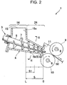
- the pressure sensors 5 are attached to a bottom portion of the casing 4 in a space S between a downstream end 15a of the supply port 15 and a tip-side opening of the casing 4 in the extrusion direction of the kneaded material.
- the pressure sensors 5 (5a and 5b) are attached to a bottom portion of a downstream part of the casing 4, that is, the casing downstream portion 24 circumferentially surrounded by a wall surface.
- the pressure sensors 5 are attached to the bottom portion of the casing 4 in the space S between the downstream end 15a of the supply port 15 and the tip-side opening of the casing 4 and in a part of an upstream region S1 on the upstream side from the middle of the space S.
- the pressure sensors 5 are attached to, of the bottom portion of the casing 4, a part close to the casing center, so as to measure pressure inside the casing 4 at a part defined by a virtual line M1 horizontally extending from a top portion T of the bottom-side center of the casing 4 and virtual lines M2 and M3 respectively extending downward from rotation centers O of the screws 2 and 3 in a sectional view of the casing 4 perpendicular to the extrusion direction of the kneaded material.
- the defined part inside the casing 4 is a part where pressure tends to be stabilized and a part where kneading operation acts on the material (kneaded material) most effectively.
- the pressure sensors 5 are attached to the casing 4 so as to prevent the tip portions (pressure detection portions) thereof from protruding from a bottom-side inner wall surface 4a of the casing 4, so that the pressure sensors 5 (5a and 5b) can be prevented from touching the flights 7 of the rotating screws 2 and 3.
- load sensors 8 are respectively attached to the shaft portions of the rollers 9 and 10 disposed in front of the casing 4, that is, on the downstream fore side of the casing 4.
- Each load sensor 8 is, for example, constituted by a strain gauge.
- the load sensors 8 are sensors for measuring respective loads of the kneaded material extruded from the bank portion 11 acting on the rollers 9 and 10.
- FIG. 4 is a pressure distribution chart in the casing downstream portion 24 when the extruder is in use.
- "O", "L”, “S” and “S1” in FIG. 4 correspond to “O", “L”, “S” and “S1” in FIGs. 1 and 2 .
- the casing 4 has a tapered shape, the volume decreases as goes toward the tip of the casing 4. Therefore, the kneaded material extruded by the screws 2 and 3 is consolidated more as approaches the tip of the casing 4.
- the pressure (pressure of the kneaded material) inside the casing 4 has a steeper increasing gradient at a place closer to the tip of the casing 4.
- "PL” designates the atmospheric pressure
- "PO” designates the pressure (pressure of the kneaded material) at the tip-side opening of the casing 4 where the sectional area is the smallest.
- the pressure inside the casing 4 in the part of the region S1 on the upstream side from the middle between the downstream end 15a of the supply port 15 and the tip-side opening of the casing 4 has a sufficient difference from each of the loads acting on the rollers 9 and 10 measured by the load sensors 8 (or pressure in the bank portion 11 in an embodiment illustrated in FIG. 7 ), and therefore is suitable for the control of the rotational speeds of the rollers 9 and 10.
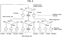
- the method for controlling the rotational speeds of screws and the rotational speeds of rollers in the extruder with roller-die 1 will be described with reference to FIG. 5 .
- the control is performed by a controller 12 (see FIG. 1 ) serving as a control unit. Signals from the pressure sensors 5 (5a and 5b) and signals from the load sensors 8 are imported to the controller 12.
- the controller 12 controls the rotational speeds of the screws 2 and 3 and the rotational speeds of the rollers 9 and 10 based on the imported signals.
- the controller 12 calculates average pressure (kneaded portion average pressure) of the pressure (kneaded portion pressure) measured by the pressure sensor 5a and the pressure (kneaded portion pressure) measured by the pressure sensor 5b. In addition, the controller 12 calculates an average load (roller average load) of the loads (roller loads) measured by the two load sensors 8.
- the signals from the respective sensors 5a, 5b and 8 are always sent to the controller 12. The signals from the respective sensors 5a, 5b and 8 may be sent to the controller 12 at fixed intervals or the like.
- the controller 12 controls the rotational speeds of the screws 2 and 3 as follows.
- the controller 12 performs control to increase the rotational speeds of the screws 2 and 3 when the kneaded portion average pressure is lower than a predetermined (allowable) pressure range, and to decrease the rotational speeds of the screws 2 and 3 when the kneaded portion average pressure is higher than the predetermined (allowable) pressure range.
- the controller 12 performs control to keep the rotational speeds of the screws 2 and 3 as they are (Step 1 (St1)).
- the kneaded portion average pressure is low means that the filling state of the kneaded material in the casing 4 (casing downstream portion 24) is low. Therefore, when the rotational speeds of the screws 2 and 3 are increased, the filling state of the kneaded material is increased.
- the fact that the kneaded portion average pressure is high means that the filling state of the kneaded material in the casing 4 (casing downstream portion 24) is high (too high). Therefore, when the rotational speeds of the screws 2 and 3 are decreased, the filling state of the kneaded material is decreased.
- the filling state of the kneaded material in the casing 4 (casing downstream portion 24) is stabilized.
- the kneaded material is kneaded stably in the casing 4 (casing downstream portion 24) by the screws 2 and 3, so that the dispersion mixing property of the kneaded material can be enhanced.
- the controller 12 controls the rotational speeds of the rollers 9 and 10 based on a combination of the value of the kneaded portion average pressure and the value of the roller average load, as follows.
- the aforementioned controls (1) to (3) can be described in another expression as follows. Independently of the value of the kneaded portion average pressure, the controller 12 performs control to decrease the rotational speeds of the rollers 9 and 10 when the roller average load is lower than the predetermined (allowable) load range, and to increase the rotational speed of the rollers 9 and 10 when the roller average load is higher than the predetermined (allowable) load range.
- the controller 12 performs control to increase, decrease or keep the rotational speeds of the rollers 9 and 10 depending on the fact that the controller 12 increases, decreases or keeps the rotational speeds of the screws 2 and 3. More specifically, the controller 12 performs control to increase the rotational speeds of the rollers 9 and 10 when increasing the rotational speeds of the screws 2 and 3, to decrease the rotational speeds of the rollers 9 and 10 when decreasing the rotational speeds of the screws 2 and 3, and to keep the rotational speeds of the rollers 9 and 10 as they are when keeping the rotational speeds of the screws 2 and 3 as they are.
- FIG. 6 is a view of an extruder with roller-die 102 according to a second embodiment of the invention.
- the extruder with roller-die 102 according to the second embodiment members which are the same as the members constituting the extruder with roller-die 1 according to the first embodiment are referenced correspondingly (the same thing can be applied to a third embodiment which will be described later).
- the extruder with roller-die 102 according to the second embodiment is different from the extruder with roller-die 1 according to the first embodiment at the point of the number of pressure sensors 5 attached to the bottom portion of the casing 4 (casing downstream portion 24).
- one pressure sensor 5 is disposed (one for each of the left chamber 4b and the right chamber 4c) in the extrusion direction of the kneaded material.
- two pressure sensors 5 are disposed (two for each of the left chamber 4b and the right chamber 4c) in the extrusion direction of the kneaded material.
- two pressure sensors 5 are attached to the bottom portion of the casing 4 in the space S between the downstream end 15a of the supply port 15 and the tip-side opening of the casing 4 for each of the left chamber 4b and the right chamber 4c in the extrusion direction of the kneaded material at predetermined axial interval.
- the two pressure sensors 5b disposed in the right chambers 4c are illustrated in FIG. 6 .
- a plurality of pressure sensors 5 are provided so that pressure can be measured at a plurality of places in the extrusion direction inside the casing 4. Due to the configuration, the pressure of the kneaded material ejected from the casing 4 can be stabilized.
- the fluctuation of the volume of the kneaded material caught between the rollers 9 and 10 can be reduced so that the kneading degree of the kneaded material in the casing 4 can be improved, and a sheet 50 stable in thickness and width can be manufactured.
- a total of four pressure sensors 5 are attached to the bottom portion of the casing 4 in the extruder with roller-die 102. As described above, the screws 2 and 3 of this embodiment are coupled and rotated at the same rotational speed. Therefore, when pressures measured by the four pressure sensors 5 are used to control the rotational speeds of the screws and the rotational speeds of the rollers, an average value of the pressures measured by the four pressure sensors 5 is used to control the rotational speeds of the screws and the rotational speeds of the rollers.
- FIG. 7 is a view of an extruder with roller-die 103 according to a third embodiment of the invention.
- the load sensors 8 are attached to the shaft portions of the rollers 9 and 10.
- a bank portion pressure sensor 13 for measuring pressure in the bank portion 11 (pressure of the kneaded material in the back portion 11) is provided between the casing 4 and the rollers 9 and 10 in place of the load sensors 8.
- the controller 12 calculates average pressure (kneaded portion average pressure) of the pressure (kneaded portion pressure) measured by the pressure sensor 5a and the pressure (kneaded portion pressure) measured by the pressure sensor 5b.
- the controller 12 controls the rotational speeds of the rollers 9 and 10 based on a combination of the value of the kneaded portion average pressure and the value of the bank portion pressure measured by the bank portion pressure sensor 13.
- FIG. 8 is a flow chart illustrating a control flow of the rotational speeds of the screws and the rotational speeds of the rollers in this embodiment.
- the rotational speeds of the screws 2 and 3 in this embodiment are controlled in the same manner as in the first embodiment.
- the "roller average load" in the description of "Control of Rotational speed of Roller " in the first embodiment is replaced by "bank portion pressure”
- the "load” in the description about the roller average load is replaced by "pressure” with reference to FIG. 8 .
- the control of the rotational speeds of the screws and the rotational speeds of the rollers can be summarized as in Table 2.
- the pressure of the kneaded material on the downstream fore side of the rollers, that is, in the bank portion 11 is stabilized in the same manner as in the first embodiment.
- the fluctuation of the volume of the kneaded material caught between the rollers 9 and 10 is reduced so that the kneading degree of the kneaded material in the casing 4 can be improved and a sheet 50 stable in thickness and width can be manufactured.
- the pair of left and right screws 2 and 3 in each aforementioned embodiment are designed to be rotated at the same rotational speed by a single driving unit.
- the screws 2 and 3 may be instead designed to be rotated independently of each other by two driving units respectively.
- the rotational speeds of the left and right screws 2 and 3 are, for example, controlled individually by the pressure sensors 5 disposed in the chambers respectively in accordance with the control flow illustrated in FIG. 5 .
- the control of the rotational speeds of the rollers 9 and 10 for example, average pressure of the pressures measured by the pressure sensors 5 provided in the left and right chambers of the casing 4 is used for the control of the rotational speeds of the rollers 9 and 10.
- Each pressure sensor 5 for measuring pressure inside the casing 4 may be attached not to the bottom portion of the casing 4 (casing downstream portion 24) but to a side portion or a top portion of the casing 4 (casing downstream portion 24).
- Two or more pressure sensors may be provided in each of the left and right chambers of the casing 4.
- Three or more pressure sensors may be attached to the casing 4 (casing downstream portion 24) in the extrusion direction of the kneaded material (in the axial direction of each screw).
- the screw extruder may be a screw extruder including not the pair of left and right screws 2 and 3 but only one screw.
Landscapes
- Engineering & Computer Science (AREA)
- Mechanical Engineering (AREA)
- Manufacturing & Machinery (AREA)
- Extrusion Moulding Of Plastics Or The Like (AREA)
- Processing And Handling Of Plastics And Other Materials For Molding In General (AREA)
Abstract
Description
- The present invention relates to a screw extruder for extruding a kneaded material.
- A process for manufacturing automobile tires uses an extrusion forming machine that is placed below a kneader which kneads rubber as the raw material of the tires. The extrusion forming machine forms the rubber (kneaded material) fed from the kneader into a sheet shape while continuously extruding it. For example, a technique described in
Patent Literature - A sheet forming apparatus described in
Patent Literature 1 has a material supply portion, a material storage portion that temporarily stores an elastic material supplied from the material supply portion, and a material rolling portion that rolls the elastic material stored in the material storage portion. Two screws are disposed in the material supply portion so that the elastic material can be sent to the material rolling portion through the material storage portion by the screws. Two rolls are disposed in the material rolling portion so that the elastic material can be formed into a sheet shape by the rolls. - A roller head extruder described in
Patent Literature 2 has an extruder body, and a calender roll device that rolls kneaded rubber extruded from the extruder body into a sheet shape. A buffer lock device is disposed between the extruder body and the calender roll device. A sensing device that senses pressure (head pressure of the extruder body) between the extruder body and the calender roll device is provided inside the buffer lock device. The speed of the calender roll and the rotational speeds of the screws in the extruder body are automatically controlled depending on the head pressure of the extruder body sensed by the sensing device.Patent Literature 2 describes that due to this configuration, troublesome manual control of skillful worker is not necessary, and a rubber sheet having a uniform width can be always obtained continuously. -
- Patent Literature 1:
JP-A-2009-12463 - Patent Literature 2:
JP-B-S55-4575 - In recent years, there have been increasing demands for fuel-efficient tires. For the rubber as the raw material of fuel-efficient tires, silica is frequently compounded in a high content. There is a problem that it is difficult to form the rubber (kneaded material) having a high content of silica into a sheet shape by the extrusion forming machine. For this reason, it is desired to enhance the dispersion mixing property of the rubber (kneaded material) not only in the kneader of the upstream side process but also in the extrusion forming machine. To enhance the dispersion mixing property of the rubber (kneaded material), (1) it is necessary to apply more energy to the kneaded material in the portion where the screws are disposed to extrude the kneaded material, and (2) it is necessary to stabilize the filling state of the kneaded material in the portion where the screws are disposed to extrude the kneaded material.
- However, either
Patent Literature Patent Literature 2, although the speed of the calender roll and the rotational speeds of the screws in the extruder body are controlled depending on the head pressure of the extruder body, this control is not to stabilize the filling state of the kneaded material in the extruder body. - The present invention has been developed in consideration of the aforementioned actual situation. An object of the invention is to solve the problem (2) of the aforementioned problems (1) and (2) for enhancing the dispersion mixing property of the kneaded material, that is, to provide a screw extruder having a configuration in which a filling state of a kneaded material can be stabilized in a portion where a screw is disposed to extrude the kneaded material.
- A screw extruder according to the invention is a screw extruder for excluding a kneaded material, including: a screw; and a casing housing the screw and having a material supply port on an upstream side in an extrusion direction of the kneaded material and a tip-side opening on a downstream side in the extrusion direction, wherein a pressure sensor for measuring a pressure inside the casing is provided between a downstream end of the supply port and the tip-side opening of the casing, and wherein a rotational speed of the screw is controlled depending on the pressure measured by the pressure sensor.
- With this configuration, the rotational speed of the screw is controlled depending on the pressure measured by the pressure sensor so that the filling state of the kneaded material inside the casing in the portion where the screw is disposed to extrude the kneaded material is stabilized. Accordingly, the kneaded material is kneaded stably by the screw in the portion where the screw is disposed. Thus, the dispersion mixing property of the kneaded material is enhanced.
- In addition, in the invention, it is preferable that an inner wall surface of the casing has an outer edge shape in which two circles partially overlap each other on the same plane in a section perpendicular to the extrusion direction of the kneaded material, wherein a pair of left and right screws, as the screw, are housed in the casing, and wherein a pressure inside the casing in a part defined in the section by a virtual line horizontally extending from a top portion at a bottom-side center of the casing and virtual lines respectively extending downward from rotation centers of the pair of left and right screws is measured by the pressure sensor.
- The above-described defined part inside the casing is a part where pressure tends to be stabilized, and a part where kneading operation acts on the material (kneaded material) most effectively. When the rotational speeds of the screws are controlled based on the pressure of the part, the filling state of the kneaded material in the casing is made more stable. In addition, since the pressure tends to be stabilized in the part, measuring the pressure in the part is suitable for evaluation of the kneading degree of the material (kneaded material).
- Further, in the invention, it is preferable that a plurality of pressure sensors, as the pressure sensor, are provided so as to measure respective pressures in a left chamber of the casing and a right chamber of the casing.
- With this configuration, even when there is a difference in filling ratio (pressure) of the kneaded material between the left and right chambers of the casing, suitable control can be made depending on the difference.
- Further, in the invention, it is preferable that a plurality of pressure sensors, as the pressure sensor, are provided so as to measure pressures at a plurality of places in the extrusion direction inside the casing.
- With this configuration, the pressure of the kneaded material ejected from the casing can be stabilized.
- Further, in the invention, it is preferable that a pair of upper and lower rollers for forming the kneaded material into a sheet shape are disposed on a downstream fore side of the casing, wherein load sensors for measuring loads acting on the rollers are provided in the rollers, and wherein rotational speeds of the rollers are controlled depending on a combination of the pressure measured by the pressure sensor and the loads measured by the load sensors.
- With this configuration, the pressure of the kneaded material before the rollers can be stabilized. Accordingly it is possible to manufacture a sheet stable in thickness and width.
- Further, in the invention, it is preferable that a pair of upper and lower rollers for forming the kneaded material into a sheet shape are disposed on a downstream fore side of the casing, wherein a bank portion pressure sensor for measuring a pressure in a bank portion that is a part between the casing and the rollers is provided in the bank portion, and wherein rotational speeds of the rollers are controlled depending on a combination of the pressure measured by the pressure sensor and the pressure measured by the bank portion pressure sensor.
- With this configuration, the pressure of the kneaded material before the rollers can be stabilized. Accordingly it is possible to manufacture a sheet stable in thickness and width.
- Further, in the invention, it is preferable that the casing has a tapered shape, wherein the pressure inside the casing on an upstream side from the middle between the downstream end of the supply port and the tip-side opening of the casing is measured by the pressure sensor.
- In the screw extruder with the pair of upper and lower rollers for forming the kneaded material into a sheet shape, according to the invention, it is intended to stabilize the filling state of the kneaded material in the casing due to the control of the rotational speed of the screw based on the pressure measured by the pressure sensor. In addition, it is intended to stabilize the thickness and width of the sheet due to the control of the rotational speeds of the rollers based on a combination of the pressure measured by the pressure sensor and the loads measured by the load sensors (or the pressure measured by the bank portion pressure sensor).
- Here, when the casing has a tapered shape, the pressure inside the casing has a steeper increasing gradient at a position closer to the tip of the casing. More rotational energy of the screw is consumed at a place where the pressure increase is large. When the pressure sensor is placed at a place where the difference from the pressure at the tip of the casing can be measured easily, it is possible to measure pressure more suitable for the control of the rotational speed of the screw.
- From such a point, it is preferable to measure the pressure inside the casing on the upstream side from the middle between the downstream end of the material supply port and the tip-side opening of the casing.
- In addition, the pressure inside the casing on the upstream side from the middle between the downstream end of the material supply port and the tip-side opening of the casing is more suitable for the control of the rotational speeds of the rollers because there is a sufficient difference from the pressure in the bank portion (or the loads acting on the rollers).
- According to the invention, it is possible to provide a screw extruder capable of stabilizing a filling state of a kneaded material in a portion where a screw is disposed to extrude the kneaded material.
-
-
FIG. 1 is a cross-sectional view of an extruder with roller-die as a first embodiment of a screw extruder according to the invention. -
FIG. 2 is a sectional view taken on II-II inFIG. 1 and a longitudinal sectional view of the extruder with roller-die in the embodiment of the present invention. -
FIG. 3 is a schematic sectional view taken on III-III inFIG. 2 . -
FIG. 4 is a pressure distribution chart in a downstream portion of a casing. -
FIG. 5 is a flow chart illustrating a control flow of the rotational speed of a screw and the rotational speeds of rollers in the extruder with roller-die illustrated inFIGs. 1 to 3 . -
FIG. 6 is a longitudinal sectional view of an extruder with roller-die as a second embodiment of a screw extruder according to the invention. -
FIG. 7 is a cross-sectional view of an extruder with roller-die as a third embodiment of a screw extruder according to the invention. -
FIG. 8 is a flow chart illustrating a control flow of the rotational speed of a screw and the rotational speeds of rollers in the extruder with roller-die illustrated inFIG. 7 . - Hereinafter, embodiments for carrying out the present invention will be described with reference to the drawings. A screw extruder illustrated in each of the following embodiments is a screw extruder with roller-die (hereinafter, referred to as "extruder with roller-die") for extruding a kneaded material of a polymer such as rubber and forms the extruded material into a sheet shape. The screw extruder according to the invention may be also applied to a machine called a pelletizer, which extrudes a kneaded material of a polymer from a die having a multiplicity of circular holes, and then cuts and forms the extruded material into cylindrical pellets.
- An extruder with roller-
die 1 according to a first embodiment of the invention will be described with reference toFIGs. 1 to 3 . The extruder with roller-die 1 includes a pair of left andright screws casing 4 housing thescrews casing 4, a pair of upper andlower rollers casing 4 and therollers bank portion 11. The kneaded material extruded by thescrews bank portion 11. Thebank portion 11 is closed. Therollers rollers rollers - Each of the
screws shaft portion 6 and ahelical flight 7 provided on the outer peripheral surface of theshaft portion 6. Thescrews screws screws - The
casing 4 has a shape tapered from the upstream side toward the downstream side in the extrusion direction of the kneaded material. Thecasing 4 includes a casingupstream portion 14 in which a material (kneaded material)supply port 15 is provided at the top thereof, and a casingdownstream portion 24 which is circumferentially surrounded by a wall surface. The kneaded material such as rubber supplied to thesupply port 15 from above is extruded to thebank portion 11 by thescrews rollers - As illustrated in
FIG. 3 , the inner wall surface of thecasing 4 has an outer edge shape (spectacles-like shape) in which two circles partially overlap each other on the same plane in a section perpendicular to the extrusion direction of the kneaded material. Thescrew 2 is housed in aleft chamber 4b of thecasing 4, and thescrew 3 is housed in aright chamber 4c of thecasing 4. Two pressure sensors 5 (5a and 5b) are attached to a bottom portion of thecasing 4. Thepressure sensor 5a is attached on theleft chamber 4b side, and thepressure sensor 5b is attached on theright chamber 4c side. Pressure (pressure of the kneaded material) inside thecasing 4 is measured by each of the pressure sensors 5 (5a and 5b). Since the pressures in the left and right chambers of thecasing 4 are measured individually, even when there is a difference in filling ratio (pressure) of the kneaded material between the left and right chambers of thecasing 4, control can be carried out suitably depending on the difference as will be described later. - As illustrated in
FIGs. 1 and2 , the pressure sensors 5 (5a and 5b) are attached to a bottom portion of thecasing 4 in a space S between adownstream end 15a of thesupply port 15 and a tip-side opening of thecasing 4 in the extrusion direction of the kneaded material. In other words, the pressure sensors 5 (5a and 5b) are attached to a bottom portion of a downstream part of thecasing 4, that is, the casingdownstream portion 24 circumferentially surrounded by a wall surface. More preferably, as in the embodiment, the pressure sensors 5 (5a and 5b) are attached to the bottom portion of thecasing 4 in the space S between thedownstream end 15a of thesupply port 15 and the tip-side opening of thecasing 4 and in a part of an upstream region S1 on the upstream side from the middle of the space S. - As illustrated in
FIG. 3 , the pressure sensors 5 (5a and 5b) are attached to, of the bottom portion of thecasing 4, a part close to the casing center, so as to measure pressure inside thecasing 4 at a part defined by a virtual line M1 horizontally extending from a top portion T of the bottom-side center of thecasing 4 and virtual lines M2 and M3 respectively extending downward from rotation centers O of thescrews casing 4 perpendicular to the extrusion direction of the kneaded material. The defined part inside thecasing 4 is a part where pressure tends to be stabilized and a part where kneading operation acts on the material (kneaded material) most effectively. When the rotational speeds (speeds of rotation) of thescrews casing 4 is made more stable. In addition, since the pressure tends to be stabilized in the part, the measurement of pressure in the part is suitable for evaluation of the kneading degree of the material (kneaded material). The pressure sensors 5 (5a and 5b) are attached to thecasing 4 so as to prevent the tip portions (pressure detection portions) thereof from protruding from a bottom-sideinner wall surface 4a of thecasing 4, so that the pressure sensors 5 (5a and 5b) can be prevented from touching theflights 7 of therotating screws - As illustrated in
FIG. 2 ,load sensors 8 are respectively attached to the shaft portions of therollers casing 4, that is, on the downstream fore side of thecasing 4. Eachload sensor 8 is, for example, constituted by a strain gauge. Theload sensors 8 are sensors for measuring respective loads of the kneaded material extruded from thebank portion 11 acting on therollers -
FIG. 4 is a pressure distribution chart in the casingdownstream portion 24 when the extruder is in use. "O", "L", "S" and "S1" inFIG. 4 correspond to "O", "L", "S" and "S1" inFIGs. 1 and2 . When thecasing 4 has a tapered shape, the volume decreases as goes toward the tip of thecasing 4. Therefore, the kneaded material extruded by thescrews casing 4. Thus, the pressure (pressure of the kneaded material) inside thecasing 4 has a steeper increasing gradient at a place closer to the tip of thecasing 4. "PL" designates the atmospheric pressure, and "PO" designates the pressure (pressure of the kneaded material) at the tip-side opening of thecasing 4 where the sectional area is the smallest. - More rotational energy of the
screws pressure sensors 5 are placed at places where the difference from the pressure at the tip of thecasing 4 can be measured easily, it is possible to measure pressure more suitable for the control of the rotational speeds of thescrews casing 4 on the upstream side from the middle (L/2) of the space S between thedownstream end 15a of thesupply port 15 and the tip-side opening of thecasing 4. In addition, the pressure inside thecasing 4 in the part of the region S1 on the upstream side from the middle between thedownstream end 15a of thesupply port 15 and the tip-side opening of thecasing 4 has a sufficient difference from each of the loads acting on therollers bank portion 11 in an embodiment illustrated inFIG. 7 ), and therefore is suitable for the control of the rotational speeds of therollers - The method for controlling the rotational speeds of screws and the rotational speeds of rollers in the extruder with roller-
die 1 will be described with reference toFIG. 5 . The control is performed by a controller 12 (seeFIG. 1 ) serving as a control unit. Signals from the pressure sensors 5 (5a and 5b) and signals from theload sensors 8 are imported to thecontroller 12. Thecontroller 12 controls the rotational speeds of thescrews rollers - The
controller 12 calculates average pressure (kneaded portion average pressure) of the pressure (kneaded portion pressure) measured by thepressure sensor 5a and the pressure (kneaded portion pressure) measured by thepressure sensor 5b. In addition, thecontroller 12 calculates an average load (roller average load) of the loads (roller loads) measured by the twoload sensors 8. When the extruder with roller-die 1 is engaging in extrusion of the kneaded material, the signals from therespective sensors controller 12. The signals from therespective sensors controller 12 at fixed intervals or the like. - Based on the value of the aforementioned kneaded portion average pressure, the
controller 12 controls the rotational speeds of thescrews - The
controller 12 performs control to increase the rotational speeds of thescrews screws controller 12 performs control to keep the rotational speeds of thescrews - The fact that the kneaded portion average pressure is low means that the filling state of the kneaded material in the casing 4 (casing downstream portion 24) is low. Therefore, when the rotational speeds of the
screws screws - Due to the aforementioned control, the filling state of the kneaded material in the casing 4 (casing downstream portion 24) is stabilized. As a result, the kneaded material is kneaded stably in the casing 4 (casing downstream portion 24) by the
screws - The
controller 12 controls the rotational speeds of therollers - (1) When the kneaded portion average pressure is lower than the predetermined (allowable) pressure range, the rotational speeds of rollers are controlled as follows. The
controller 12 performs control to decrease the rotational speeds of therollers rollers controller 12 performs control to increase the rotational speeds of therollers 9 and 10 (Step 2_1 (St2_1)). - (2) When the kneaded portion average pressure is higher than the predetermined (allowable) pressure range, the rotational speeds of rollers are controlled as follows. The
controller 12 performs control to decrease the rotational speeds of therollers rollers controller 12 performs control to decrease the rotational speeds of therollers 9 and 10 (Step 2_3 (St2_3)). - (3) When the kneaded portion average pressure is within the predetermined (allowable) pressure range, the rotational speeds of rollers are controlled as follows. The
controller 12 performs control to decrease the rotational speeds of therollers rollers controller 12 performs control to keep the rotational speeds of therollers - The aforementioned controls (1) to (3) can be described in another expression as follows. Independently of the value of the kneaded portion average pressure, the
controller 12 performs control to decrease the rotational speeds of therollers rollers - On the other hand, when the roller average load is within the predetermined (allowable) load range, that is, proper (within the proper range), the
controller 12 performs control to increase, decrease or keep the rotational speeds of therollers controller 12 increases, decreases or keeps the rotational speeds of thescrews controller 12 performs control to increase the rotational speeds of therollers screws rollers screws rollers screws - When the rotational speeds of the rollers are controlled in the aforementioned manner, the pressure of the kneaded material on the upstream side from the rollers, that is, in the
bank portion 11 is stabilized. Thus, the fluctuation of the volume of the kneaded material caught between therollers casing 4 can be improved, and asheet 50 stable in thickness and width can be manufactured. - The aforementioned control of the rotational speeds of the screws and the rotational speeds of the rollers can be summarized as in Table 1.
Table 1 Roller average load Low Roller average load Proper range Roller average load High Kneaded portion average pressure Rotational speed of screw: increase Rotational speed of screw: increase Rotational speed of screw: increase Low Rotational speed of roller: decrease Rotational speed of roller: increase Rotational speed of roller: increase Kneaded portion average pressure Rotational speed of screw: keep Rotational speed of screw: keep Rotational speed of screw: keep Proper range Rotational speed of roller: decrease Rotational speed of roller: keep Rotational speed of roller: increase Kneaded portion average pressure Rotational speed of screw: decrease Rotational speed of screw: decrease Rotational speed of screw: decrease High Rotational speed of roller: decrease Rotational speed of roller: decrease Rotational speed of roller: increase -
FIG. 6 is a view of an extruder with roller-die 102 according to a second embodiment of the invention. As for the extruder with roller-die 102 according to the second embodiment, members which are the same as the members constituting the extruder with roller-die 1 according to the first embodiment are referenced correspondingly (the same thing can be applied to a third embodiment which will be described later). - The extruder with roller-die 102 according to the second embodiment is different from the extruder with roller-
die 1 according to the first embodiment at the point of the number ofpressure sensors 5 attached to the bottom portion of the casing 4 (casing downstream portion 24). In the extruder with roller-die 1 according to the first embodiment, onepressure sensor 5 is disposed (one for each of theleft chamber 4b and theright chamber 4c) in the extrusion direction of the kneaded material. On the other hand, in the extruder with roller-die 102 according to the second embodiment, twopressure sensors 5 are disposed (two for each of theleft chamber 4b and theright chamber 4c) in the extrusion direction of the kneaded material. - Specifically, in the extruder with roller-
die 102, twopressure sensors 5 are attached to the bottom portion of thecasing 4 in the space S between thedownstream end 15a of thesupply port 15 and the tip-side opening of thecasing 4 for each of theleft chamber 4b and theright chamber 4c in the extrusion direction of the kneaded material at predetermined axial interval. The twopressure sensors 5b disposed in theright chambers 4c are illustrated inFIG. 6 . In this manner, according to this embodiment, a plurality ofpressure sensors 5 are provided so that pressure can be measured at a plurality of places in the extrusion direction inside thecasing 4. Due to the configuration, the pressure of the kneaded material ejected from thecasing 4 can be stabilized. Thus, the fluctuation of the volume of the kneaded material caught between therollers casing 4 can be improved, and asheet 50 stable in thickness and width can be manufactured. - A total of four
pressure sensors 5 are attached to the bottom portion of thecasing 4 in the extruder with roller-die 102. As described above, thescrews pressure sensors 5 are used to control the rotational speeds of the screws and the rotational speeds of the rollers, an average value of the pressures measured by the fourpressure sensors 5 is used to control the rotational speeds of the screws and the rotational speeds of the rollers. -
FIG. 7 is a view of an extruder with roller-die 103 according to a third embodiment of the invention. In the extruder with roller-die 1 according to the first embodiment, theload sensors 8 are attached to the shaft portions of therollers portion pressure sensor 13 for measuring pressure in the bank portion 11 (pressure of the kneaded material in the back portion 11) is provided between thecasing 4 and therollers load sensors 8. - In the same manner as in the first embodiment, the
controller 12 calculates average pressure (kneaded portion average pressure) of the pressure (kneaded portion pressure) measured by thepressure sensor 5a and the pressure (kneaded portion pressure) measured by thepressure sensor 5b. - In this embodiment, the
controller 12 controls the rotational speeds of therollers portion pressure sensor 13. -
FIG. 8 is a flow chart illustrating a control flow of the rotational speeds of the screws and the rotational speeds of the rollers in this embodiment. The rotational speeds of thescrews rollers FIG. 8 . The control of the rotational speeds of the screws and the rotational speeds of the rollers can be summarized as in Table 2.Table 2 Bank portion pressure Bank portion pressure Bank portion pressure Low Proper range High Kneaded portion average pressure Rotational speed of screw: increase Rotational speed of screw: increase Rotational speed of screw: increase Low Rotational speed of roller: decrease Rotational speed of roller: increase Rotational speed of roller: increase Kneaded portion average pressure Rotational speed of screw: keep Rotational speed of screw: keep Rotational speed of screw: keep Proper range Rotational speed of roller: decrease Rotational speed of roller: keep Rotational speed of roller: increase Kneaded portion average pressure Rotational speed of screw: decrease Rotational speed of screw: decrease Rotational speed of screw: decrease High Rotational speed of roller: decrease Rotational speed of roller: decrease Rotational speed of roller: increase - Due to the aforementioned control about the rotational speeds of the rollers, the pressure of the kneaded material on the downstream fore side of the rollers, that is, in the
bank portion 11 is stabilized in the same manner as in the first embodiment. Thus, the fluctuation of the volume of the kneaded material caught between therollers casing 4 can be improved and asheet 50 stable in thickness and width can be manufactured. - The pair of left and
right screws screws pressure sensors 5 are provided in the left and right chambers of thecasing 4 respectively as in the aforementioned first embodiment, the rotational speeds of the left andright screws pressure sensors 5 disposed in the chambers respectively in accordance with the control flow illustrated inFIG. 5 . As for the control of the rotational speeds of therollers pressure sensors 5 provided in the left and right chambers of thecasing 4 is used for the control of the rotational speeds of therollers - Each
pressure sensor 5 for measuring pressure inside the casing 4 (casing downstream portion 24) may be attached not to the bottom portion of the casing 4 (casing downstream portion 24) but to a side portion or a top portion of the casing 4 (casing downstream portion 24). - Two or more pressure sensors may be provided in each of the left and right chambers of the
casing 4. - Three or more pressure sensors may be attached to the casing 4 (casing downstream portion 24) in the extrusion direction of the kneaded material (in the axial direction of each screw).
- The screw extruder may be a screw extruder including not the pair of left and
right screws - In addition, various modifications may be made within the scope that one of ordinary skill in the art can arrive at.
- The present application is based on Japanese Patent Application No.
2016-198850 filed on October 7, 2016 -
- 1: Extruder with roller-die (screw extruder)
- 2, 3: Screw
- 4: Casing
- T: Top portion
- M1, M2, M3: Virtual line
- O: Rotation center
- 5: Pressure sensor
- 8: Load
- 9, 10: Roller
- 12: Controller
- 13: Bank portion pressure sensor
- 15: Supply port
- 15a: Downstream end
Claims (10)
- A screw extruder for extruding a kneaded material, comprising:a screw; anda casing housing the screw and having a material supply port on an upstream side in an extrusion direction of the kneaded material and a tip-side opening on a downstream side in the extrusion direction,wherein a pressure sensor for measuring a pressure inside the casing is provided between a downstream end of the supply port and the tip-side opening of the casing, andwherein a rotational speed of the screw is controlled depending on the pressure measured by the pressure sensor.
- The screw extruder according to Claim 1,
wherein an inner wall surface of the casing has an outer edge shape in which two circles partially overlap each other on the same plane in a section perpendicular to the extrusion direction of the kneaded material,
wherein a pair of left and right screws, as the screw, are housed in the casing, and
wherein a pressure inside the casing in a part defined in the section by a virtual line horizontally extending from a top portion at a bottom-side center of the casing and virtual lines respectively extending downward from rotation centers of the pair of left and right screws is measured by the pressure sensor. - The screw extruder according to Claim 2,
wherein a plurality of pressure sensors, as the pressure sensor, are provided so as to measure respective pressures in a left chamber of the casing and a right chamber of the casing. - The screw extruder according to Claim 1,
wherein a plurality of pressure sensors, as the pressure sensor, are provided so as to measure pressures at a plurality of places in the extrusion direction inside the casing. - The screw extruder according to Claim 2,
wherein a plurality of pressure sensors, as the pressure sensor, are provided so as to measure pressures at a plurality of places in the extrusion direction inside the casing. - The screw extruder according to Claim 3,
wherein a plurality of pressure sensors, as the pressure sensor, are provided so as to measure pressures at a plurality of places in the extrusion direction inside the casing. - The screw extruder according to any one of Claims 1 to 6,
wherein a pair of upper and lower rollers for forming the kneaded material into a sheet shape are disposed on a downstream fore side of the casing,
wherein load sensors for measuring loads acting on the rollers are provided in the rollers, and
wherein rotational speeds of the rollers are controlled depending on a combination of the pressure measured by the pressure sensor and the loads measured by the load sensors. - The screw extruder according to Claim 7,
wherein the casing has a tapered shape, and
wherein the pressure inside the casing on an upstream side from the middle between the downstream end of the supply port and the tip-side opening of the casing is measured by the pressure sensor. - The screw extruder according to any one of Claims 1 to 6,
wherein a pair of upper and lower rollers for forming the kneaded material into a sheet shape are disposed on a downstream fore side of the casing,
wherein a bank portion pressure sensor for measuring a pressure in a bank portion that is a part between the casing and the rollers is provided in the bank portion, and
wherein rotational speeds of the rollers are controlled depending on a combination of the pressure measured by the pressure sensor and the pressure measured by the bank portion pressure sensor. - The screw extruder according to Claim 9,
wherein the casing has a tapered shape, and
wherein the pressure inside the casing on an upstream side from the middle between the downstream end of the supply port and the tip-side opening of the casing is measured by the pressure sensor.
Applications Claiming Priority (2)
| Application Number | Priority Date | Filing Date | Title |
|---|---|---|---|
| JP2016198850A JP6662747B2 (en) | 2016-10-07 | 2016-10-07 | Screw type extruder |
| PCT/JP2017/032495 WO2018066304A1 (en) | 2016-10-07 | 2017-09-08 | Screw extruder |
Publications (2)
| Publication Number | Publication Date |
|---|---|
| EP3524404A1 true EP3524404A1 (en) | 2019-08-14 |
| EP3524404A4 EP3524404A4 (en) | 2020-06-10 |
Family
ID=61831695
Family Applications (1)
| Application Number | Title | Priority Date | Filing Date |
|---|---|---|---|
| EP17858143.5A Withdrawn EP3524404A4 (en) | 2016-10-07 | 2017-09-08 | Screw extruder |
Country Status (7)
| Country | Link |
|---|---|
| US (1) | US20200031017A1 (en) |
| EP (1) | EP3524404A4 (en) |
| JP (1) | JP6662747B2 (en) |
| KR (1) | KR102150920B1 (en) |
| CN (1) | CN109863011B (en) |
| TW (1) | TWI641472B (en) |
| WO (1) | WO2018066304A1 (en) |
Cited By (2)
| Publication number | Priority date | Publication date | Assignee | Title |
|---|---|---|---|---|
| EP3797967A4 (en) * | 2018-06-25 | 2021-08-04 | Kabushiki Kaisha Kobe Seiko Sho (Kobe Steel, Ltd.) | SCREW EXTRUDER |
| WO2021165870A1 (en) * | 2020-02-20 | 2021-08-26 | Pomini Rubber & Plastics S.R.L. | Apparatus and method for mixing elastomeric materials |
Families Citing this family (2)
| Publication number | Priority date | Publication date | Assignee | Title |
|---|---|---|---|---|
| JP6947096B2 (en) | 2018-03-26 | 2021-10-13 | 三菱マテリアル株式会社 | Manufacturing method of insulated superconducting wire |
| EP4603256A1 (en) * | 2024-02-16 | 2025-08-20 | Bridgestone Europe NV/SA | Automatic system to control a physical property level of rubber mixed by a continuous mixer |
Family Cites Families (23)
| Publication number | Priority date | Publication date | Assignee | Title |
|---|---|---|---|---|
| JPS5463183A (en) * | 1977-10-31 | 1979-05-21 | Yokohama Rubber Co Ltd | Roller head extruder |
| IN150686B (en) * | 1978-03-09 | 1982-11-20 | Usm Corp | |
| JPS554575A (en) | 1978-06-27 | 1980-01-14 | Noboru Nakatani | Method and apparatus for measuring flow velocity distribution and flow rate by laser doppler method |
| US4428896A (en) * | 1982-08-30 | 1984-01-31 | The General Tire & Rubber Company | Method of producing an extrudate of controlled size and shape from a roller die |
| US4541270A (en) * | 1984-03-01 | 1985-09-17 | American Maplan Corporation | Apparatus for testing plastic compositions |
| GB2237239B (en) * | 1989-10-27 | 1993-09-01 | Reifenhaeuser Masch | A process for the production of a ribbon of synthetic thermoplastic material in sheet form |
| JPH04214320A (en) * | 1990-12-12 | 1992-08-05 | Sekisui Chem Co Ltd | Screw extruder |
| JPH0647797A (en) * | 1992-07-29 | 1994-02-22 | Sekisui Chem Co Ltd | Method for controlling extrusion machine |
| JP2698037B2 (en) * | 1993-09-14 | 1998-01-19 | 株式会社神戸製鋼所 | Extruder bank amount adjustment device |
| JP3611347B2 (en) * | 1994-10-20 | 2005-01-19 | 東芝機械株式会社 | Method and apparatus for measuring internal state of twin-screw extruder |
| JP2871565B2 (en) * | 1995-12-26 | 1999-03-17 | 株式会社神戸製鋼所 | Roller head extruder and control method thereof |
| JP4318829B2 (en) * | 2000-02-29 | 2009-08-26 | 三ツ星ベルト株式会社 | Roller head extruder and roller head extrusion method |
| JP4294005B2 (en) * | 2005-05-02 | 2009-07-08 | 株式会社モリヤマ | Control method of roller head extruder |
| JP4607209B2 (en) | 2007-06-06 | 2011-01-05 | 株式会社モリヤマ | Sheet forming equipment |
| AT505618B1 (en) * | 2007-10-22 | 2009-03-15 | Erema | PROCESS FOR EXTRUSION OF PLASTIC MATERIAL AND EXTRUDER |
| KR20110099960A (en) * | 2010-03-03 | 2011-09-09 | 조선대학교산학협력단 | Single screw extruder screw and die using computational fluid analysis |
| KR20110099957A (en) * | 2010-03-03 | 2011-09-09 | 조선대학교산학협력단 | Single Screw Screw Polymer Extruder |
| JP5773302B2 (en) * | 2010-05-13 | 2015-09-02 | 株式会社ニイガタマシンテクノ | High shear device and high shear method |
| JP6242886B2 (en) * | 2012-06-28 | 2017-12-06 | ダウ グローバル テクノロジーズ エルエルシー | Multilayer microcapillary film manufacturing method and apparatus |
| FR3001654B1 (en) * | 2013-02-01 | 2015-06-19 | Michelin & Cie | APPARATUS AND METHOD FOR EXTRUDING ELASTOMER MIXTURE |
| DE102013005199A1 (en) * | 2013-03-25 | 2014-09-25 | Maag Pump Systems Gmbh | Method for controlling a melt-processing plant |
| CN104693819B (en) * | 2015-02-12 | 2019-01-22 | 天津海泰环保科技发展股份有限公司 | A kind of stable storing, ageing-resistant composite S BS particle asphalt modifier and preparation method thereof |
| JP6497185B2 (en) | 2015-04-09 | 2019-04-10 | 本田技研工業株式会社 | Autonomous mobile device and control method of autonomous mobile device |
-
2016
- 2016-10-07 JP JP2016198850A patent/JP6662747B2/en not_active Expired - Fee Related
-
2017
- 2017-09-08 WO PCT/JP2017/032495 patent/WO2018066304A1/en not_active Ceased
- 2017-09-08 KR KR1020197009313A patent/KR102150920B1/en not_active Expired - Fee Related
- 2017-09-08 CN CN201780062007.8A patent/CN109863011B/en not_active Expired - Fee Related
- 2017-09-08 EP EP17858143.5A patent/EP3524404A4/en not_active Withdrawn
- 2017-09-08 US US16/337,370 patent/US20200031017A1/en not_active Abandoned
- 2017-09-21 TW TW106132383A patent/TWI641472B/en not_active IP Right Cessation
Cited By (2)
| Publication number | Priority date | Publication date | Assignee | Title |
|---|---|---|---|---|
| EP3797967A4 (en) * | 2018-06-25 | 2021-08-04 | Kabushiki Kaisha Kobe Seiko Sho (Kobe Steel, Ltd.) | SCREW EXTRUDER |
| WO2021165870A1 (en) * | 2020-02-20 | 2021-08-26 | Pomini Rubber & Plastics S.R.L. | Apparatus and method for mixing elastomeric materials |
Also Published As
| Publication number | Publication date |
|---|---|
| CN109863011B (en) | 2021-03-12 |
| KR102150920B1 (en) | 2020-09-02 |
| WO2018066304A1 (en) | 2018-04-12 |
| CN109863011A (en) | 2019-06-07 |
| JP6662747B2 (en) | 2020-03-11 |
| KR20190046927A (en) | 2019-05-07 |
| EP3524404A4 (en) | 2020-06-10 |
| US20200031017A1 (en) | 2020-01-30 |
| JP2018058308A (en) | 2018-04-12 |
| TW201825258A (en) | 2018-07-16 |
| TWI641472B (en) | 2018-11-21 |
Similar Documents
| Publication | Publication Date | Title |
|---|---|---|
| EP3524404A1 (en) | Screw extruder | |
| US4209476A (en) | Method and apparatus for fabrication of extruded articles | |
| CN101631666B (en) | Apparatus for the manufacture of rubber strip material | |
| JP6814709B2 (en) | Screw extruder with roll | |
| US20160052192A1 (en) | Method for regulating the thickness profile of inline-oriented films | |
| JP7107122B2 (en) | Rubber material extrusion method and system | |
| JPH029616A (en) | Homogenizing performance improving device for cold feeding rubber extruder | |
| JP4365732B2 (en) | Rubber sheet forming device | |
| US20190389114A1 (en) | Screw-type extruder | |
| JPH0474173B2 (en) | ||
| KR20110056850A (en) | Apparatus and method for controlling extrusion speed of extruder | |
| WO2019031351A1 (en) | Screw extruder with rollers | |
| JP6740595B2 (en) | Rubber extrusion equipment | |
| EP3501784B1 (en) | Method for supplying material to extruder | |
| Potente et al. | Description of the foaming process during the extrusion of foams based on renewable resources | |
| JP5507528B2 (en) | Feed extruder and feed extrusion method | |
| KR100563869B1 (en) | Rubber sheet manufacturing method and manufacturing apparatus | |
| JP2016093954A (en) | Rubber extrusion molding device and method | |
| EP1549477A1 (en) | Method and apparatus for feeding an expanding agent |
Legal Events
| Date | Code | Title | Description |
|---|---|---|---|
| STAA | Information on the status of an ep patent application or granted ep patent |
Free format text: STATUS: THE INTERNATIONAL PUBLICATION HAS BEEN MADE |
|
| PUAI | Public reference made under article 153(3) epc to a published international application that has entered the european phase |
Free format text: ORIGINAL CODE: 0009012 |
|
| STAA | Information on the status of an ep patent application or granted ep patent |
Free format text: STATUS: REQUEST FOR EXAMINATION WAS MADE |
|
| 17P | Request for examination filed |
Effective date: 20190405 |
|
| AK | Designated contracting states |
Kind code of ref document: A1 Designated state(s): AL AT BE BG CH CY CZ DE DK EE ES FI FR GB GR HR HU IE IS IT LI LT LU LV MC MK MT NL NO PL PT RO RS SE SI SK SM TR |
|
| AX | Request for extension of the european patent |
Extension state: BA ME |
|
| DAV | Request for validation of the european patent (deleted) | ||
| DAX | Request for extension of the european patent (deleted) | ||
| A4 | Supplementary search report drawn up and despatched |
Effective date: 20200513 |
|
| RIC1 | Information provided on ipc code assigned before grant |
Ipc: B29C 48/32 20190101ALI20200507BHEP Ipc: B29C 43/34 20060101ALI20200507BHEP Ipc: B29K 21/00 20060101ALN20200507BHEP Ipc: B29K 509/00 20060101ALN20200507BHEP Ipc: B29C 48/40 20190101ALI20200507BHEP Ipc: B29K 105/16 20060101ALN20200507BHEP Ipc: B29B 7/48 20060101ALI20200507BHEP Ipc: B29C 48/41 20190101ALI20200507BHEP Ipc: B29C 43/58 20060101ALI20200507BHEP Ipc: B29B 7/74 20060101ALI20200507BHEP Ipc: B29B 7/72 20060101ALI20200507BHEP Ipc: B29C 43/46 20060101ALN20200507BHEP Ipc: B29C 48/92 20190101AFI20200507BHEP Ipc: B29C 48/395 20190101ALI20200507BHEP Ipc: B29C 48/30 20190101ALI20200507BHEP |
|
| STAA | Information on the status of an ep patent application or granted ep patent |
Free format text: STATUS: EXAMINATION IS IN PROGRESS |
|
| 17Q | First examination report despatched |
Effective date: 20210204 |
|
| GRAP | Despatch of communication of intention to grant a patent |
Free format text: ORIGINAL CODE: EPIDOSNIGR1 |
|
| STAA | Information on the status of an ep patent application or granted ep patent |
Free format text: STATUS: GRANT OF PATENT IS INTENDED |
|
| RIC1 | Information provided on ipc code assigned before grant |
Ipc: B29K 509/00 20060101ALN20210825BHEP Ipc: B29K 21/00 20060101ALN20210825BHEP Ipc: B29C 43/46 20060101ALN20210825BHEP Ipc: B29K 105/16 20060101ALN20210825BHEP Ipc: B29C 48/08 20190101ALI20210825BHEP Ipc: B29B 7/60 20060101ALI20210825BHEP Ipc: B29B 7/52 20060101ALI20210825BHEP Ipc: B29C 48/41 20190101ALI20210825BHEP Ipc: B29C 48/395 20190101ALI20210825BHEP Ipc: B29C 48/30 20190101ALI20210825BHEP Ipc: B29B 7/74 20060101ALI20210825BHEP Ipc: B29B 7/72 20060101ALI20210825BHEP Ipc: B29B 7/48 20060101ALI20210825BHEP Ipc: B29C 43/58 20060101ALI20210825BHEP Ipc: B29C 43/34 20060101ALI20210825BHEP Ipc: B29C 48/40 20190101ALI20210825BHEP Ipc: B29C 48/32 20190101ALI20210825BHEP Ipc: B29C 48/92 20190101AFI20210825BHEP |
|
| INTG | Intention to grant announced |
Effective date: 20210909 |
|
| RIC1 | Information provided on ipc code assigned before grant |
Ipc: B29K 509/00 20060101ALN20210830BHEP Ipc: B29K 21/00 20060101ALN20210830BHEP Ipc: B29C 43/46 20060101ALN20210830BHEP Ipc: B29K 105/16 20060101ALN20210830BHEP Ipc: B29C 48/08 20190101ALI20210830BHEP Ipc: B29B 7/60 20060101ALI20210830BHEP Ipc: B29B 7/52 20060101ALI20210830BHEP Ipc: B29C 48/41 20190101ALI20210830BHEP Ipc: B29C 48/395 20190101ALI20210830BHEP Ipc: B29C 48/30 20190101ALI20210830BHEP Ipc: B29B 7/74 20060101ALI20210830BHEP Ipc: B29B 7/72 20060101ALI20210830BHEP Ipc: B29B 7/48 20060101ALI20210830BHEP Ipc: B29C 43/58 20060101ALI20210830BHEP Ipc: B29C 43/34 20060101ALI20210830BHEP Ipc: B29C 48/40 20190101ALI20210830BHEP Ipc: B29C 48/32 20190101ALI20210830BHEP Ipc: B29C 48/92 20190101AFI20210830BHEP |
|
| STAA | Information on the status of an ep patent application or granted ep patent |
Free format text: STATUS: THE APPLICATION IS DEEMED TO BE WITHDRAWN |
|
| 18D | Application deemed to be withdrawn |
Effective date: 20220120 |