EP3524339A1 - Method and system for increasing the thickness of a carbon nanotube sheet structure - Google Patents
Method and system for increasing the thickness of a carbon nanotube sheet structure Download PDFInfo
- Publication number
- EP3524339A1 EP3524339A1 EP18382078.6A EP18382078A EP3524339A1 EP 3524339 A1 EP3524339 A1 EP 3524339A1 EP 18382078 A EP18382078 A EP 18382078A EP 3524339 A1 EP3524339 A1 EP 3524339A1
- Authority
- EP
- European Patent Office
- Prior art keywords
- cnts
- sheet
- continuous sheet
- drying
- continuous
- Prior art date
- Legal status (The legal status is an assumption and is not a legal conclusion. Google has not performed a legal analysis and makes no representation as to the accuracy of the status listed.)
- Granted
Links
Images


Classifications
-
- B—PERFORMING OPERATIONS; TRANSPORTING
- B01—PHYSICAL OR CHEMICAL PROCESSES OR APPARATUS IN GENERAL
- B01D—SEPARATION
- B01D67/00—Processes specially adapted for manufacturing semi-permeable membranes for separation processes or apparatus
- B01D67/0081—After-treatment of organic or inorganic membranes
- B01D67/0095—Drying
-
- C—CHEMISTRY; METALLURGY
- C04—CEMENTS; CONCRETE; ARTIFICIAL STONE; CERAMICS; REFRACTORIES
- C04B—LIME, MAGNESIA; SLAG; CEMENTS; COMPOSITIONS THEREOF, e.g. MORTARS, CONCRETE OR LIKE BUILDING MATERIALS; ARTIFICIAL STONE; CERAMICS; REFRACTORIES; TREATMENT OF NATURAL STONE
- C04B30/00—Compositions for artificial stone, not containing binders
- C04B30/02—Compositions for artificial stone, not containing binders containing fibrous materials
-
- B—PERFORMING OPERATIONS; TRANSPORTING
- B01—PHYSICAL OR CHEMICAL PROCESSES OR APPARATUS IN GENERAL
- B01D—SEPARATION
- B01D67/00—Processes specially adapted for manufacturing semi-permeable membranes for separation processes or apparatus
- B01D67/0039—Inorganic membrane manufacture
- B01D67/0041—Inorganic membrane manufacture by agglomeration of particles in the dry state
- B01D67/00412—Inorganic membrane manufacture by agglomeration of particles in the dry state by deposition of fibres, nanofibres or nanofibrils
-
- B—PERFORMING OPERATIONS; TRANSPORTING
- B01—PHYSICAL OR CHEMICAL PROCESSES OR APPARATUS IN GENERAL
- B01D—SEPARATION
- B01D67/00—Processes specially adapted for manufacturing semi-permeable membranes for separation processes or apparatus
- B01D67/0039—Inorganic membrane manufacture
- B01D67/0041—Inorganic membrane manufacture by agglomeration of particles in the dry state
- B01D67/00416—Inorganic membrane manufacture by agglomeration of particles in the dry state by deposition by filtration through a support or base layer
-
- B—PERFORMING OPERATIONS; TRANSPORTING
- B01—PHYSICAL OR CHEMICAL PROCESSES OR APPARATUS IN GENERAL
- B01D—SEPARATION
- B01D67/00—Processes specially adapted for manufacturing semi-permeable membranes for separation processes or apparatus
- B01D67/0081—After-treatment of organic or inorganic membranes
- B01D67/0083—Thermal after-treatment
-
- B—PERFORMING OPERATIONS; TRANSPORTING
- B01—PHYSICAL OR CHEMICAL PROCESSES OR APPARATUS IN GENERAL
- B01D—SEPARATION
- B01D67/00—Processes specially adapted for manufacturing semi-permeable membranes for separation processes or apparatus
- B01D67/0081—After-treatment of organic or inorganic membranes
- B01D67/0086—Mechanical after-treatment
-
- B—PERFORMING OPERATIONS; TRANSPORTING
- B01—PHYSICAL OR CHEMICAL PROCESSES OR APPARATUS IN GENERAL
- B01D—SEPARATION
- B01D69/00—Semi-permeable membranes for separation processes or apparatus characterised by their form, structure or properties; Manufacturing processes specially adapted therefor
- B01D69/06—Flat membranes
-
- B—PERFORMING OPERATIONS; TRANSPORTING
- B01—PHYSICAL OR CHEMICAL PROCESSES OR APPARATUS IN GENERAL
- B01D—SEPARATION
- B01D69/00—Semi-permeable membranes for separation processes or apparatus characterised by their form, structure or properties; Manufacturing processes specially adapted therefor
- B01D69/10—Supported membranes; Membrane supports
-
- B—PERFORMING OPERATIONS; TRANSPORTING
- B01—PHYSICAL OR CHEMICAL PROCESSES OR APPARATUS IN GENERAL
- B01D—SEPARATION
- B01D71/00—Semi-permeable membranes for separation processes or apparatus characterised by the material; Manufacturing processes specially adapted therefor
- B01D71/02—Inorganic material
- B01D71/021—Carbon
- B01D71/0211—Graphene or derivates thereof
-
- B—PERFORMING OPERATIONS; TRANSPORTING
- B01—PHYSICAL OR CHEMICAL PROCESSES OR APPARATUS IN GENERAL
- B01D—SEPARATION
- B01D71/00—Semi-permeable membranes for separation processes or apparatus characterised by the material; Manufacturing processes specially adapted therefor
- B01D71/02—Inorganic material
- B01D71/021—Carbon
- B01D71/0212—Carbon nanotubes
-
- B—PERFORMING OPERATIONS; TRANSPORTING
- B29—WORKING OF PLASTICS; WORKING OF SUBSTANCES IN A PLASTIC STATE IN GENERAL
- B29D—PRODUCING PARTICULAR ARTICLES FROM PLASTICS OR FROM SUBSTANCES IN A PLASTIC STATE
- B29D99/00—Subject matter not provided for in other groups of this subclass
- B29D99/005—Producing membranes
-
- B—PERFORMING OPERATIONS; TRANSPORTING
- B82—NANOTECHNOLOGY
- B82Y—SPECIFIC USES OR APPLICATIONS OF NANOSTRUCTURES; MEASUREMENT OR ANALYSIS OF NANOSTRUCTURES; MANUFACTURE OR TREATMENT OF NANOSTRUCTURES
- B82Y30/00—Nanotechnology for materials or surface science, e.g. nanocomposites
-
- B—PERFORMING OPERATIONS; TRANSPORTING
- B82—NANOTECHNOLOGY
- B82Y—SPECIFIC USES OR APPLICATIONS OF NANOSTRUCTURES; MEASUREMENT OR ANALYSIS OF NANOSTRUCTURES; MANUFACTURE OR TREATMENT OF NANOSTRUCTURES
- B82Y40/00—Manufacture or treatment of nanostructures
-
- C—CHEMISTRY; METALLURGY
- C01—INORGANIC CHEMISTRY
- C01B—NON-METALLIC ELEMENTS; COMPOUNDS THEREOF; METALLOIDS OR COMPOUNDS THEREOF NOT COVERED BY SUBCLASS C01C
- C01B32/00—Carbon; Compounds thereof
- C01B32/15—Nano-sized carbon materials
- C01B32/158—Carbon nanotubes
-
- C—CHEMISTRY; METALLURGY
- C01—INORGANIC CHEMISTRY
- C01B—NON-METALLIC ELEMENTS; COMPOUNDS THEREOF; METALLOIDS OR COMPOUNDS THEREOF NOT COVERED BY SUBCLASS C01C
- C01B32/00—Carbon; Compounds thereof
- C01B32/15—Nano-sized carbon materials
- C01B32/158—Carbon nanotubes
- C01B32/168—After-treatment
-
- D—TEXTILES; PAPER
- D21—PAPER-MAKING; PRODUCTION OF CELLULOSE
- D21F—PAPER-MAKING MACHINES; METHODS OF PRODUCING PAPER THEREON
- D21F11/00—Processes for making continuous lengths of paper, or of cardboard, or of wet web for fibre board production, on paper-making machines
-
- D—TEXTILES; PAPER
- D21—PAPER-MAKING; PRODUCTION OF CELLULOSE
- D21H—PULP COMPOSITIONS; PREPARATION THEREOF NOT COVERED BY SUBCLASSES D21C OR D21D; IMPREGNATING OR COATING OF PAPER; TREATMENT OF FINISHED PAPER NOT COVERED BY CLASS B31 OR SUBCLASS D21G; PAPER NOT OTHERWISE PROVIDED FOR
- D21H13/00—Pulp or paper, comprising synthetic cellulose or non-cellulose fibres or web-forming material
- D21H13/36—Inorganic fibres or flakes
- D21H13/46—Non-siliceous fibres, e.g. from metal oxides
- D21H13/50—Carbon fibres
-
- F—MECHANICAL ENGINEERING; LIGHTING; HEATING; WEAPONS; BLASTING
- F26—DRYING
- F26B—DRYING SOLID MATERIALS OR OBJECTS BY REMOVING LIQUID THEREFROM
- F26B13/00—Machines and apparatus for drying fabrics, fibres, yarns, or other materials in long lengths, with progressive movement
-
- F—MECHANICAL ENGINEERING; LIGHTING; HEATING; WEAPONS; BLASTING
- F26—DRYING
- F26B—DRYING SOLID MATERIALS OR OBJECTS BY REMOVING LIQUID THEREFROM
- F26B13/00—Machines and apparatus for drying fabrics, fibres, yarns, or other materials in long lengths, with progressive movement
- F26B13/10—Arrangements for feeding, heating or supporting materials; Controlling movement, tension or position of materials
-
- F—MECHANICAL ENGINEERING; LIGHTING; HEATING; WEAPONS; BLASTING
- F26—DRYING
- F26B—DRYING SOLID MATERIALS OR OBJECTS BY REMOVING LIQUID THEREFROM
- F26B13/00—Machines and apparatus for drying fabrics, fibres, yarns, or other materials in long lengths, with progressive movement
- F26B13/10—Arrangements for feeding, heating or supporting materials; Controlling movement, tension or position of materials
- F26B13/101—Supporting materials without tension, e.g. on or between foraminous belts
- F26B13/103—Supporting materials without tension, e.g. on or between foraminous belts with mechanical supporting means, e.g. belts, rollers, and fluid impingement arrangement having a displacing effect on the materials
-
- F—MECHANICAL ENGINEERING; LIGHTING; HEATING; WEAPONS; BLASTING
- F26—DRYING
- F26B—DRYING SOLID MATERIALS OR OBJECTS BY REMOVING LIQUID THEREFROM
- F26B13/00—Machines and apparatus for drying fabrics, fibres, yarns, or other materials in long lengths, with progressive movement
- F26B13/10—Arrangements for feeding, heating or supporting materials; Controlling movement, tension or position of materials
- F26B13/14—Rollers, drums, cylinders; Arrangement of drives, supports, bearings, cleaning
-
- B—PERFORMING OPERATIONS; TRANSPORTING
- B01—PHYSICAL OR CHEMICAL PROCESSES OR APPARATUS IN GENERAL
- B01D—SEPARATION
- B01D2323/00—Details relating to membrane preparation
- B01D2323/08—Specific temperatures applied
- B01D2323/081—Heating
-
- B—PERFORMING OPERATIONS; TRANSPORTING
- B01—PHYSICAL OR CHEMICAL PROCESSES OR APPARATUS IN GENERAL
- B01D—SEPARATION
- B01D2323/00—Details relating to membrane preparation
- B01D2323/34—Use of radiation
-
- B—PERFORMING OPERATIONS; TRANSPORTING
- B01—PHYSICAL OR CHEMICAL PROCESSES OR APPARATUS IN GENERAL
- B01D—SEPARATION
- B01D2323/00—Details relating to membrane preparation
- B01D2323/42—Details of membrane preparation apparatus
-
- B—PERFORMING OPERATIONS; TRANSPORTING
- B01—PHYSICAL OR CHEMICAL PROCESSES OR APPARATUS IN GENERAL
- B01D—SEPARATION
- B01D2323/00—Details relating to membrane preparation
- B01D2323/50—Control of the membrane preparation process
-
- B—PERFORMING OPERATIONS; TRANSPORTING
- B01—PHYSICAL OR CHEMICAL PROCESSES OR APPARATUS IN GENERAL
- B01D—SEPARATION
- B01D2323/00—Details relating to membrane preparation
- B01D2323/64—Use of a temporary support
-
- B—PERFORMING OPERATIONS; TRANSPORTING
- B01—PHYSICAL OR CHEMICAL PROCESSES OR APPARATUS IN GENERAL
- B01D—SEPARATION
- B01D2325/00—Details relating to properties of membranes
- B01D2325/04—Characteristic thickness
Definitions
- the present invention relates to the manufacturing of materials and structures. More particularly, it refers to methods and systems for manufacturing materials and structures from carbon nanotubes, also referred to as buckypaper (BP).
- BP buckypaper
- Carbon nanotubes are used in the manufacturing of high performance material and devices.
- Processes for the continuous manufacturing of CNT-based BPs have been disclosed in the last years. Such processes typically include making a suspension of CNTs dispersed in a liquid medium and filtering the suspension by moving a filter membrane through the suspension, such that the CNTs are deposited directly on the filter membrane as the fluid medium flows through the filter membrane. The continuous BP is then dried, after which it can be separated from the filter membrane.
- An example of this process is disclosed in US7459121 B2 .
- US2016/0177511A1 discloses a method for continuous manufacturing of a CNT sheet in which a porous plate flanked by two guiding rollers acts as filtration area and is disposed within a suspension chamber filled with a suspension of CNTs.
- a filter paper is advanced to the filtration area.
- CNTs are deposited on the portion of the filter paper in contact with the filtration area.
- the portion of the filter paper with the deposited CNTs is then advanced to a drying area. After drying, the filter paper is separated from the continuous sheet of CNTs, thus obtaining a roll of filter paper and a roll of continuous sheet of CNTs.
- WO2016/019143A1 A similar approach is disclosed in WO2016/019143A1 , in which a volume of a CNT suspension is passed over a filter material and drawn through the filter material to provide a uniform dispersion of the CNTs over the filter material.
- the filter material is in the form of a continuous porous belt.
- the filtered CNT structure is dried prior to removing the CNT sheet from the porous filter material.
- the time required for obtaining a sheet of CNTs of a predetermined thickness with the conventional manufacturing processes is relatively high, as a consequence of which these processes are of poor efficiency.
- the thickness increasing rate slows down.
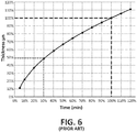
- the thickness vs filtering time curve has a non-linear behavior, as shown for example in figure 6 , which shows a thickness vs filtration time graph in a conventional BP continuous manufacturing pilot line.
- the thickness of the BP is expressed in ⁇ m (microns, 10 -6 meters), while the time is expressed in minutes.
- 50% of the thickness is generated. Thickness generation slows down as BP thickness increases. This effect is even greater for larger target thickness.
- the present disclosure provides a new method and system for increasing the thickness of a sheet of CNTs or buckypaper (BP).
- a buckypaper is a thin sheet made from an aggregate of carbon nanotubes or carbon nanotube grid paper. Because when manufacturing a CNT sheet, its thickness increase rate is reduced as its thickness increases, obtaining the last portion of aimed thickness (typically several microns or ⁇ m) requires more time than the previous ones.
- the present disclosure provides a method that enables increasing the last portion of aimed thickness in a much faster process, in such a way that the above-mentioned slowing effect is minimized and the time required for obtaining the sheet of CNTs of a desired thickness is reduced.
- the aimed thickness of BP may be obtained as follows: First, a first amount of thickness of BP may be obtained by any conventional method, and then, a second amount of thickness (the remaining amount until the desired thickness is reached) may be additionally obtained by means of the method of the present disclosure. As a matter of example, the first amount of thickness may be around 85% of the aimed thickness. This may result in a time saving of about 25% for a same aimed thickness.
- the buckypaper (or sheet of CNTs) whose thickness is increased may be obtained in the form of a continuous sheet, or in the form of batch portions (single portions).
- a continuous sheet of material is an elongated sheet having a length that is orders of magnitude greater than the width of the sheet.
- the continuous sheet of material may be provided in the form of a roll of the sheet material.
- a continuous sheet of material may be obtained by performing a continuous manufacturing process.
- a batch portion or single portion of material is a portion having length and width of same or similar order of magnitude.
- the sheet of CNTs may be circular or rectangular or of any other shape. When it is rectangular, the sheet may be continuous (for example to be provided in a roll) or noncontinuous, also referred to as batch or portion (for example a portion of length and width of similar order of magnitude). The width and length of the sheets of CNTs may vary depending on the manufacturing process.
- the present disclosure also provides a new method and system for drying a wet sheet of CNTs, the drying method being continuous, intermittent or static.
- the drying method of this disclosure optimizes the drying stage in a process of manufacturing a sheet of CNTs, the sheets being either continuous or batch. With the proposed drying method, the thickness of the sheet of CNTs is increased, and therefore the manufacturing speed is also increased.
- the present disclosure also provides a new method and system for manufacturing a sheet of CNTs, in which the stage of drying the wet sheet of CNTs (either continuous or batch) is optimized.
- the inventors have observed that, when manufacturing a sheet of CNTs by applying vacuum and a filter material, for example as disclosed in WO2016/019143A1 , some CNTs get trapped in the pores of the mentioned filter. The inventors have also observed that, due to such trapping forces, the dimensions of the sheet of CNTs cannot change during drying.
- the wet sheet of CNTs is separated from any filter material. In other words, the wet sheet of CNTs is dried without filter material or support. This way the effect of the CNTs trapped in the filter material pores is eliminated, thus enabling changes in dimensions during drying, in particular increasing the thickness.
- the process for increasing the thickness of a sheet of CNTs is applied during the manufacturing process of a sheet of CNTs, the wet sheet of CNTs is dried after separating the CNTs sheet from the filter material.
- the process for increasing the thickness of a sheet of CNTs is applied long after the manufacturing process of the sheet of CNTs, for example when the sheet of CNTs is provided/commercialized together with a support, the sheet of CNTs is separated from the support, then soaked in an aqueous solution, such as in water, and finally the drying process for increasing its thickness is applied.
- the methods and systems of this disclosure enable the obtaining of sheets of CNTs, either continuous or batch, at a relatively fast rate compared to conventional setups due to the increasing in thickness achieved in the proposed drying stage.
- the method for increasing the thickness of a sheet or CNTs or buckypaper of the present disclosure may be applicable to any sheet of CNTs or buckypaper obtained from any conventional manufacturing process.
- the areal weight of the sheet of CNTs prior to applying the drying method of the present disclosure may be adjusted by tailoring the manufacturing conditions, such as the concentration of the CNT suspension, the applied vacuum pressure, the filtration speed, the filtration duration, the type of filter (for example of the grillage) or a combination thereof, during the manufacturing process.
- the thickness of the sheets of CNTs obtained in the method of the present disclosure has been observed to be substantially higher than the thickness of sheets of CNTs dried prior to separating the sheet of CNTs from the filter support, considering identical sheets of CNTs and identical drying conditions.
- the thickness of sheets of CNTs of the present disclosure (dried without any support material, that is to say, after separating the sheet of CNTs from the any support material) is up to 15% larger than the thickness of sheets of CNTs dried prior to separating the sheet of CNTs from any support. In some embodiments of the invention, it is up to 13% larger, or up to 11% larger, or up to 8% larger or up to 6% larger.
- a wet sheet of CNTs is used.
- the wet sheet of CNTs may be obtained by applying a conventional method for manufacturing sheets of CNTs. In embodiments of the invention, it is obtained as follows: in a container filled with a liquid solution comprising CNTs at certain concentration, submerging a vacuum tank having a lower surface forming a grillage; moving an elongated filtering membrane along the lower surface of the vacuum tank while vacuum is applied on the elongated filtering membrane in such a way that in the surface of the filtering membrane opposed to the surface in contact with the lower surface of the vacuum tank CNTs are deposited forming a continuous sheet of CNTs of constant thickness; taking the filtering membrane together with the continuous sheet of CNTs out of the container; washing the continuous sheet of CNTs disposed on the filtering membrane or on a support element in a second container filled with cleaning solution; taking the continuous sheet of CNTs together with the filtering membrane or the support element (54)
- the continuous sheet of CNTs is separated from the filtering membrane or the support element.
- the wet sheet of CNTs may be obtained by soaking in an aqueous solution a dry sheet of CNTs.
- the dry sheet of CNTs may be in the form of a roll of continuous sheet of CNTs, or a portion of sheet of CNTs, that has been manufactured by any conventional manufacturing process.
- a first aspect of the invention refers to a method for increasing the thickness of a sheet of CNTs, comprising: providing a wet sheet of CNTs, wherein the sheet of CNTs is either a continuous sheet of CNTs or a portion of sheet of CNTs, wherein the wet sheet of CNTs is the result of applying a process for manufacturing a sheet of CNTs; separating the wet sheet of CNTs from any filter or support element; drying the wet sheet of CNTs by applying heat from a heat source.
- the wet sheet of CNTs being the result of applying a process for manufacturing a sheet of CNTs is obtained by soaking in a liquid medium a dry sheet of CNTs already manufactured.
- the sheet of CNTs is continuous or a single portion thereof (batch portion).
- the drying stage implies a continuous advancing of the sheet of CNTs, or an intermittent advancing thereof, or is static.
- the sheet of CNTs is a continuous sheet of CNTs and the drying of the wet continuous sheet of CNTs is done as follows: moving forward the wet continuous sheet of CNTs in a longitudinal direction until a portion thereof is disposed within a drying unit comprising the heat source, the heat source being configured to provide heat to a drying area, the drying unit further comprising screening means for delimiting said drying area, in such a way that the portion of continuous sheet of CNTs is subject to heat only until while it is under the drying area.
- the drying unit may comprise a plurality of rollers configured to rotate freely and to guide the continuous sheet of CNTs along its longitudinal direction, forcing the continuous sheet of CNTs to adopt soft convex and concave curvatures in an alternate way.
- the plurality of rollers may comprise a central roller disposed under the drying area and lateral rollers disposed under the screening means.
- the drying unit may comprise two conveyor belts configured to guide the continuous sheet of CNTs in its longitudinal direction, the conveyor belts being longitudinally disposed above and below the continuous sheet of CNTs, respectively.
- At least one of the conveyor belts may be made of a porous material or comprises a grillage, in order to favour the entrance of heat and also to favour liquid evaporation, therefore reducing the drying time.
- the heating source is an infrared irradiation source or a convection source or hot air source, or an ultra-violet (UV) irradiation source or an electrical resistance (ER) radiation source, or a conduction source.
- UV ultra-violet
- ER electrical resistance
- the thickness of the resulting sheet of CNTs is increased.
- the resulting sheet of CNTs has uniform thickness increase without causing any irregular deformations such as wrinkles and buckling.
- a second aspect of the invention refers to a method for manufacturing a continuous sheet of CNTs, comprising: in a container filled with a liquid solution comprising CNTs at certain concentration, submerging a vacuum tank having a lower surface forming a grillage; moving an elongated filtering membrane along the lower surface of the vacuum tank while vacuum is applied on the elongated filtering membrane in such a way that in the surface of the filtering membrane opposed to the surface in contact with the lower surface of the vacuum tank CNTs are deposited forming a continuous sheet of CNTs of constant thickness; taking the filtering membrane together with the continuous sheet of CNTs out of the container; separating the continuous sheet of CNTs from the filtering membrane or the support element; drying the continuous sheet of CNTs by applying the method already disclosed.
- the method may comprise washing the continuous sheet of CNTs disposed on the filtering membrane or on a support element in a second container filled with cleaning solution; taking the continuous sheet of CNTs together with the filtering membrane or the support element out of the second container.
- the invention provides a sheet of CNTs with increased thickness with respect to conventional ones, considering similar conditions (filtering and optionally washing stage).
- the resulting sheet of CNTs has uniform thickness increase without causing any irregular deformations such as wrinkles and buckling.
- a third aspect of the invention refers to a system for increasing the thickness of a sheet of CNTs , the system comprising a drying unit comprising a heat source configured to provide heat to a drying area, the drying area being configured to receive the sheet of CNTs.
- the sheet of CNTs is continuous, the drying area being configured to receive the wet continuous sheet of CNTs as it moves forward in its longitudinal direction, the drying unit further comprising screening means for delimiting said drying area, in such a way that the portion of continuous sheet of CNTs is subject to heat only until while it is under the drying area.
- the drying area may comprise means for preventing deformation of the continuous sheet of CNTs during the drying stage, said means being either a plurality of rollers configured to rotate freely and to guide the continuous sheet of CNTs along its longitudinal direction, forcing the continuous sheet of CNTs to adopt soft convex and concave curvatures in an alternate way, or two conveyor belts configured to guide the continuous sheet of CNTs in its longitudinal direction.
- Figures 1A, 1B , 2 and 3 show different embodiments of systems for increasing the thickness of a sheet of CNTs, or for drying a sheet of CNTs.
- the sheet of CNTs that is subject to the method of the invention must be wet.
- the sheet of CNTs may be wet because it has left a filtering stage or a washing stage in a process for manufacturing sheets of CNTs, as described in relation with figures 4 and 5 .
- the sheet of CNTs may be wet because an already dry sheet of CNTs (which is dry for example because it has been manufactured well in advanced) has been soaked in an aqueous solution on purpose in order to apply the method of the invention.
- the sheet of CNTs is preferably totally wet, for example because it has just left a filtering stage such as the one shown in figure 4 , or a washing stage such as the one shown in figure 5 , or because it has just been totally soaked, for example submerged in an aqueous solution.
- a possible method that may be used for manufacturing a wet sheet of CNTs is disclosed in view of figures 4-5 .
- the manufactured sheet of CNTs is continuous and stored in rolls.
- a filtering stage is shown in figure 4 .
- an optional washing stage is shown in figure 5 .
- a similar approach may be applied, mutatis mutandis, for manufacturing batch sheets of CNTs (not continuous sheets provided for example in rolls).
- FIG. 4 shows a schematic representation of a filtering stage of a process for manufacturing a wet continuous sheet of CNTs.
- a container 41 is filled with a liquid solution 42 comprising CNTs at certain concentration.
- a vacuum tank 43 is submerged in the container 41.
- the vacuum tank 43 has a lower surface forming a grillage.
- An elongated filtering membrane 44 is moved along the lower surface of the vacuum tank 43, at a certain speed, while constant vacuum is applied to the filtering membrane 44 in a constant way by means of a vacuum valve, not illustrated, in order to remove solution 42 from the container 41.
- CNTs are deposited on the surface of the filtering membrane 44 opposed to the surface in contact with the lower surface of the vacuum tank 43, forming a continuous sheet of CNTs 45 of substantially constant thickness.
- the filtering membrane 44 may be provided in rolls, not illustrated, that are unrolled, typically in an automatic way, while the unrolled membrane 44 moves into the container 41.
- the filtering membrane 44 with the continuous sheet of CNTs 45 deposited thereon may be rolled up while it leaves the container 41, forming a roll (not shown).
- the filtering area, in which the CNTs are deposited on a portion of the filtering membrane 44 is identified and referred to as 46. The speed of this stage depends on the desired thickness of the sheet of CNTs 45.
- the continuous sheet of CNTs may enter a washing stage, as shown in figure 5 .
- the filtering membrane 54 together with the continuous sheet of CNTs 55, is moved into a second container 51 filled with cleaning solution 52.
- Another vacuum tank 53 is submerged in the second container 51.
- Constant vacuum is applied by means of a vacuum valve, in order to remove cleaning solution from the container, in such a way that the continuous sheet of CNTs 55 is washed in contact with the cleaning solution.
- the filtering membrane 54 with the cleaned continuous sheet of CNTs 55 continuously leaves the container 51 in a wet state.
- the applied vacuum pressure and the speed may be tailored in order to control the characteristics of the wet continuous sheet of CNTs 55.
- the sheet of CNTs must be wet (for example, as it comes from the washing stage illustrated in figure 5 ).
- the wet sheet of CNTs is dried without the filter support used to manufacture that sheet of CNT or without any other kind of support.
- the wet sheet of CNTs is naked, that is to say, separated from the filter support (for example filtering membrane) with which it leaves a filtering stage (for example the one in figure 4 ), or separated from the support with which it leaves a washing stage (for example the one in figure 5 ), or separated from any support with which an already dry manufactured sheet of CNTs is typically commercialized.
- the continuous sheet of CNTs 55 is separated from the filtering material 54 prior to the drying stage.
- a roll (not shown) comprising the wet continuous sheet of CNTs 55 together with any support, is continuously unrolled. While it is unrolled, the sheet of CNTs is separated from any filtering or support element.
- FIG. 1A shows a schematic representation of a first system for carrying out the method of the invention.
- the shown configuration is suitable for increasing the thickness of a batch portion of sheet of CNTs 146.
- a drying unit 11 is shown.
- the wet sheet of CNTs 146 is disposed on a surface 19 subject to the heat 15 provided by a heat source 12.
- the heat source 12 is configured to provide heat 15 to a drying area 13, under which or within which the sheet of CNTs 146 is placed.
- the heat source 12 may be movable.
- the static (single portion) of sheet of CNTs 146 is thus exposed to heat 15. After certain time, which depends on the original thickness of the sheet of CNTs 146, the sheet of CNTs is dried.
- the heating source 12 may be implemented in different ways.
- an infrared (IR) irradiation source is used.
- a convection source or hot air source is used.
- Other radiation sources such as a ultra-violet (UV) irradiation source or an electrical resistance (ER) radiation source, may be used instead.
- UV ultra-violet
- ER electrical resistance
- FIG 1B shows a schematic representation of a second system for carrying out the method of the invention.
- This system is similar to the one in figure 1A .
- the system in figure 1B is suitable for increasing the thickness of a continuous sheet of CNTs.
- the continuous sheet of CNTs, wet and already separated from the filter used to manufacture the sheet of CNTs, may be provided in rolls 145.
- a drying unit 11 is shown.
- the wet continuous sheet of CNTs, forming a roll 145 is moved forward while it is unrolled 147 towards the drying unit 11.
- the sheet of CNTs may be moved automatically, for example actioned by driving means (for example actioning the roll 148 at the outside of the drying unit 11).
- the continuous sheet of CNTs 147 may be moved continuously, at low speed, or may be moved portion by portion, in an intermittent way, that is to say, it may be moved until a first portion of sheet of CNTs is disposed within the working area of the drying area 13 and then stopped for a time sufficient to dry that first portion. And then the sheet of CNTs is moved forward until a second portion thereof is disposed within the working area of the drying area 13, and so on.
- the continuous sheet of CNTs 147 is heated while the continuous sheet of CNT is progressively moved, either continuously or intermittently, in its longitudinal direction. The heat 15 is applied locally, that is to say, only under or within the operation of the drying area 13.
- the driving means of the continuous sheet of CNTs 147 is preferably disposed outside the drying unit 11.
- the drying unit 11 has a heat source 12 configured to provide heat 15 to a drying area 13.
- the heat source 12 may be movable.
- the drying area 13 is delimited by screening means 16, configured to delimit the drying area 13, preventing the heat 15 from passing through the screening means 16, and to delimit the drying time, in particular in the event of continuous movement of the sheet of CNTs.
- the screening means 16 may be implemented by means of two fixed screens or two movable screens.
- the screening means 16 may be of any material capable of blocking the heat emitted by the heat source, and of supporting the working temperature.
- the screens may be made of metal plates that can be fixed in different positions depending on the desired drying area.
- the heating source 12 may be implemented in the same possible ways as described in relation to figure 1A . After application of this continuous process, the thickness of the resulting dry sheet of CNTs 149 has been increased. However, certain deformation in the sheet of CNTs may be produced, in particular at the longitudinal sides, due to uneven drying, contraction forces or any other possible source of deformation. This potential deformation is solved as proposed in the implementations of figures 2 and 3 .
- Figures 2 and 3 show different systems for carrying out the method of the invention, in which irregular deformation of the sheet of CNTs, which may occur in the drying process, is prevented by using means for preventing deformation.
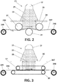
- FIG. 2 shows a schematic representation of a third system for carrying out the method of the invention.
- the system in figure 2 is suitable for increasing the thickness of a continuous sheet of CNTs. It additionally avoids undesired bending of the longitudinal edges of the sheet of CNTs.
- a drying unit 21 is shown.
- the wet continuous sheet of CNTs, that may be forming a roll 245, is advanced while it is unrolled 246 towards the drying unit 21.
- the sheet of CNTs 246 may be moved automatically.
- the drying unit 21 has a heat source 22 configured to provide heat 25 to a drying area 23.
- the drying area 23 is delimited by screening means 26, having the same purpose and implementation as the screening means 16 in the second system.
- first roll 245 of wet continuous sheet of CNTs at the input of the drying unit 21 and a second roll 248 of dried continuous sheet of CNTs at the output of the drying unit 21 there is a first roll 245 of wet continuous sheet of CNTs at the input of the drying unit 21 and a second roll 248 of dried continuous sheet of CNTs at the output of the drying unit 21.
- a plurality of rollers 27, 28, 29 guide the continuous sheet of CNTs 246.
- three rollers are shown. The rollers roll freely, without being actioned. They contribute to avoid deformations in the continuous sheet of CNTs 246.
- the first and third rollers 27, 29 are preferably disposed respectively at the input and output of the drying area 23. For example, they may be disposed beneath the screening means 26.
- the continuous sheet of CNTs is unrolled 246, it is obliged to move under the first roller 27, forming a concave shape. Then, for example when it is exposed to heat 25 in the drying area 23, the continuous sheet of CNTs is obliged to move above the second roller 28 (central roller), forming a convex shape. Next, at the output of the drying area 23, the continuous sheet of CNTs is obliged to move under the third roller 29, following the path it defines, forming a concave shape.
- rollers are possible.
- the first and third rollers 27, 28 may be disposed beneath the sheet of CNTs, in such a way that the continuous sheet of CNTs is obliged to move above the first roller 27, forming a convex shape, then under the second roller 28 (disposed in this case above the sheet of CNTs), forming a concave shape, and finally above the third roller 29, forming again a convex shape.
- the three rollers 27-29 may be of the same shape and diameter.
- the central roller 28 may have a larger diameter.
- the rollers 27-29 are referred to as straightening rolls, since they prevent deformation in the continuous sheet of CNTs.
- the rollers 27-29 force the continuous sheet of CNTs 246 advancing in its longitudinal direction, to depart from the horizontal plane several degrees.
- the sheet of CNTs may form an angle up to 20o (degrees) with respect to the horizontal plane when it passes above/below the corresponding rollers 27-29.
- the angle may be for example up to 15o, or up to 12o, or up to 10o.
- the heating source 22 may be implemented in different ways.
- an infrared (IR) irradiation source is used.
- a convection source or hot air source is used.
- Other radiation sources such as a ultra-violet (UV) irradiation source or an electrical resistance (ER) radiation source, may be used instead.
- FIG 3 shows a schematic representation of a fourth system for carrying out the method of the invention.
- the system in figure 3 is suitable for increasing the thickness of a continuous sheet of CNTs. It additionally avoids undesired bending of the longitudinal edges of the sheet of CNTs.
- a drying unit 31, similar to drying units 11 21, is shown.
- the wet continuous sheet of CNTs, for example forming a roll 345, is advanced while it is unrolled 346 towards the drying unit 31.
- the sheet of CNTs may be moved automatically by means of driving means preferably located outside the drying unit 31 (for example actioning the second roll 348).
- the drying unit 31 has a heat source 32 configured to provide heat 35 to a drying area 33.
- a similar screening means 36 to the one used in the second and third systems, is used in this drying unit 31.
- the unrolled continuous sheet of CNTs 346, 347 is supported or guided by two support materials in order to prevent deformation of the sheet of CNTs, such as deformations in its longitudinal edges.
- the support materials may be implemented as conveyor belts 37, 38.
- a first conveyor belt 37 is disposed above the continuous sheet of CNTs 346, 347, longitudinally thereto, and very closed to its upper surface, preventing the sheet of CNTs from deforming upwards.
- a second conveyor belt 38 is disposed below the continuous sheet of CNTs 346, 347, longitudinally thereto, and very closed to its lower surface, therefore parallel to the first conveyor belt 37, preventing the sheet of CNTs from deforming downwards.
- the conveyor belts 37, 38 slightly press the sheet of CNTs in opposing directions, in order to maintain it straight (unwrinkled).
- the conveyor belts 37, 38 may be made of a porous material or may comprise a grillage, in order to favour the entrance of heat and also to favour liquid evaporation, therefore reducing the drying time.
- the already dried continuous sheet of CNTs 347 may be continuously rolled, forming a roll 348.
- the heating source 32 may be implemented in different ways.
- an infrared (IR) irradiation source is used.
- a convection source or hot air source is used.
- Other radiation sources such as a ultra-violet (UV) irradiation source or an electrical resistance (ER) radiation source, may be used instead.
- UV ultra-violet
- ER electrical resistance
- a first portion of sheet of CNTs produced by means of a conventional method for manufacturing sheets of CNTs has been subjected to a conventional drying stage, that is to say, it has been dried without separating the sheet of CNTs from the filter support (or support, in general), with which the sheet of CNTs is washed.
- a second portion of sheet of CNTs is produced by means of exactly the same manufacturing method. It has the same dimensions as the first one. In fact, in some experiments the same BP has been cut in two portions (or more) that have been dried differently to have comparable results. However, instead of drying the sheet of CNTs without separating the sheet of CNTs from the filter support with which the sheet of CNTs was washed, both elements were separated and the method of the invention was applied. In particular, a system similar to the one shown in figure 3 has been used. The heat source was the same infrared radiation source.
- This experiment proves the capacity of the method of the invention to increase the thickness of the resulting sheet of CNTs. It is remarked that this comparison has been established, instead of comparing the same wet portion of sheet of CNTs before and after applying the method of the invention, because it is extremely complicated to correctly measure the thickness of a wet sheet of CNTs. Besides, the purpose of the method is to increase its thickness with respect to sheets of CNTs manufactured by means of conventional methods, in which the stage of drying is performed without separating the sheet of CNTs from the filter element.
- the method of the invention permits to save production time, thus increasing efficiency, thanks to the obtained increase in the thickness of the sheet of CNTs.
- the graph represented in figure 6 shows the thickness vs time curve corresponding to a conventional process for manufacturing a sheet of CNTs.
- the behavior of this curve is not linear: in 30% of the nominal time, 50% of the thickness is generated.
- the filtration time is defined by the line speed.
- the production capacity (sqm) is also dependent on the line speed: higher line speeds lead to higher BP production (sqm) of lower thickness, while lower line speeds lead to lower BP production (sqm) of higher thickness.
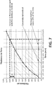
- the method of the invention permits to obtain an increase in thickness of about 13%, the approximately last 22% of time required for achieving certain thickness using a conventional manufacturing method is saved.
Landscapes
- Chemical & Material Sciences (AREA)
- Engineering & Computer Science (AREA)
- Nanotechnology (AREA)
- Chemical Kinetics & Catalysis (AREA)
- Inorganic Chemistry (AREA)
- Materials Engineering (AREA)
- Manufacturing & Machinery (AREA)
- Organic Chemistry (AREA)
- Physics & Mathematics (AREA)
- Mechanical Engineering (AREA)
- Textile Engineering (AREA)
- General Engineering & Computer Science (AREA)
- Condensed Matter Physics & Semiconductors (AREA)
- General Physics & Mathematics (AREA)
- Crystallography & Structural Chemistry (AREA)
- Thermal Sciences (AREA)
- Ceramic Engineering (AREA)
- Composite Materials (AREA)
- Structural Engineering (AREA)
- Carbon And Carbon Compounds (AREA)
- Paper (AREA)
Abstract
Description
- The present invention relates to the manufacturing of materials and structures. More particularly, it refers to methods and systems for manufacturing materials and structures from carbon nanotubes, also referred to as buckypaper (BP).
- Carbon nanotubes (CNTs) are used in the manufacturing of high performance material and devices. Processes for the continuous manufacturing of CNT-based BPs have been disclosed in the last years. Such processes typically include making a suspension of CNTs dispersed in a liquid medium and filtering the suspension by moving a filter membrane through the suspension, such that the CNTs are deposited directly on the filter membrane as the fluid medium flows through the filter membrane. The continuous BP is then dried, after which it can be separated from the filter membrane. An example of this process is disclosed in
US7459121 B2 . -
US2016/0177511A1 discloses a method for continuous manufacturing of a CNT sheet in which a porous plate flanked by two guiding rollers acts as filtration area and is disposed within a suspension chamber filled with a suspension of CNTs. A filter paper is advanced to the filtration area. When vacuum pressure is applied, CNTs are deposited on the portion of the filter paper in contact with the filtration area. The portion of the filter paper with the deposited CNTs is then advanced to a drying area. After drying, the filter paper is separated from the continuous sheet of CNTs, thus obtaining a roll of filter paper and a roll of continuous sheet of CNTs. - A similar approach is disclosed in
WO2016/019143A1 , in which a volume of a CNT suspension is passed over a filter material and drawn through the filter material to provide a uniform dispersion of the CNTs over the filter material. The filter material is in the form of a continuous porous belt. The filtered CNT structure is dried prior to removing the CNT sheet from the porous filter material. - However, the time required for obtaining a sheet of CNTs of a predetermined thickness with the conventional manufacturing processes is relatively high, as a consequence of which these processes are of poor efficiency. Moreover, as the thickness of the CNT sheet increases, the thickness increasing rate slows down. In other words, the thickness vs filtering time curve has a non-linear behavior, as shown for example in
figure 6 , which shows a thickness vs filtration time graph in a conventional BP continuous manufacturing pilot line. The thickness of the BP is expressed in µm (microns, 10-6 meters), while the time is expressed in minutes. As can be seen infigure 6 , when targeting 100% of the thickness, in 30% of the nominal time, 50% of the thickness is generated. Thickness generation slows down as BP thickness increases. This effect is even greater for larger target thickness. - The present disclosure provides a new method and system for increasing the thickness of a sheet of CNTs or buckypaper (BP). A buckypaper is a thin sheet made from an aggregate of carbon nanotubes or carbon nanotube grid paper. Because when manufacturing a CNT sheet, its thickness increase rate is reduced as its thickness increases, obtaining the last portion of aimed thickness (typically several microns or µm) requires more time than the previous ones. The present disclosure provides a method that enables increasing the last portion of aimed thickness in a much faster process, in such a way that the above-mentioned slowing effect is minimized and the time required for obtaining the sheet of CNTs of a desired thickness is reduced. So, the aimed thickness of BP may be obtained as follows: First, a first amount of thickness of BP may be obtained by any conventional method, and then, a second amount of thickness (the remaining amount until the desired thickness is reached) may be additionally obtained by means of the method of the present disclosure. As a matter of example, the first amount of thickness may be around 85% of the aimed thickness. This may result in a time saving of about 25% for a same aimed thickness.
- The buckypaper (or sheet of CNTs) whose thickness is increased may be obtained in the form of a continuous sheet, or in the form of batch portions (single portions). In the context of the present disclosure, a continuous sheet of material is an elongated sheet having a length that is orders of magnitude greater than the width of the sheet. The continuous sheet of material may be provided in the form of a roll of the sheet material. A continuous sheet of material may be obtained by performing a continuous manufacturing process. In the context of the present disclosure, a batch portion or single portion of material is a portion having length and width of same or similar order of magnitude.
- The sheet of CNTs may be circular or rectangular or of any other shape. When it is rectangular, the sheet may be continuous (for example to be provided in a roll) or noncontinuous, also referred to as batch or portion (for example a portion of length and width of similar order of magnitude). The width and length of the sheets of CNTs may vary depending on the manufacturing process.
- The present disclosure also provides a new method and system for drying a wet sheet of CNTs, the drying method being continuous, intermittent or static. The drying method of this disclosure optimizes the drying stage in a process of manufacturing a sheet of CNTs, the sheets being either continuous or batch. With the proposed drying method, the thickness of the sheet of CNTs is increased, and therefore the manufacturing speed is also increased.
- The present disclosure also provides a new method and system for manufacturing a sheet of CNTs, in which the stage of drying the wet sheet of CNTs (either continuous or batch) is optimized.
- The inventors have observed that, when manufacturing a sheet of CNTs by applying vacuum and a filter material, for example as disclosed in
WO2016/019143A1 , some CNTs get trapped in the pores of the mentioned filter. The inventors have also observed that, due to such trapping forces, the dimensions of the sheet of CNTs cannot change during drying. In the present disclosure, the wet sheet of CNTs is separated from any filter material. In other words, the wet sheet of CNTs is dried without filter material or support. This way the effect of the CNTs trapped in the filter material pores is eliminated, thus enabling changes in dimensions during drying, in particular increasing the thickness. This means that, when the process for increasing the thickness of a sheet of CNTs is applied during the manufacturing process of a sheet of CNTs, the wet sheet of CNTs is dried after separating the CNTs sheet from the filter material. Or, when the process for increasing the thickness of a sheet of CNTs is applied long after the manufacturing process of the sheet of CNTs, for example when the sheet of CNTs is provided/commercialized together with a support, the sheet of CNTs is separated from the support, then soaked in an aqueous solution, such as in water, and finally the drying process for increasing its thickness is applied. - The methods and systems of this disclosure enable the obtaining of sheets of CNTs, either continuous or batch, at a relatively fast rate compared to conventional setups due to the increasing in thickness achieved in the proposed drying stage.
- The method for increasing the thickness of a sheet or CNTs or buckypaper of the present disclosure may be applicable to any sheet of CNTs or buckypaper obtained from any conventional manufacturing process. The areal weight of the sheet of CNTs prior to applying the drying method of the present disclosure, may be adjusted by tailoring the manufacturing conditions, such as the concentration of the CNT suspension, the applied vacuum pressure, the filtration speed, the filtration duration, the type of filter (for example of the grillage) or a combination thereof, during the manufacturing process.
- The thickness of the sheets of CNTs obtained in the method of the present disclosure, that is to say, dried after separating the sheet of CNTs from any support, such as a filter support, has been observed to be substantially higher than the thickness of sheets of CNTs dried prior to separating the sheet of CNTs from the filter support, considering identical sheets of CNTs and identical drying conditions. In particular, it has been observed that the thickness of sheets of CNTs of the present disclosure (dried without any support material, that is to say, after separating the sheet of CNTs from the any support material) is up to 15% larger than the thickness of sheets of CNTs dried prior to separating the sheet of CNTs from any support. In some embodiments of the invention, it is up to 13% larger, or up to 11% larger, or up to 8% larger or up to 6% larger.
- In some embodiments of the invention, the thickness of the resulting sheet of CNTs, which has been increased up to 15% with respect to drying before separation of sheet and support, varies between 40 and 100 µm (1 µm = 1 micron = 10-6 meters).
- In order to apply the method for increasing the thickness of a sheet of CNTs, a wet sheet of CNTs is used. The wet sheet of CNTs may be obtained by applying a conventional method for manufacturing sheets of CNTs. In embodiments of the invention, it is obtained as follows: in a container filled with a liquid solution comprising CNTs at certain concentration, submerging a vacuum tank having a lower surface forming a grillage; moving an elongated filtering membrane along the lower surface of the vacuum tank while vacuum is applied on the elongated filtering membrane in such a way that in the surface of the filtering membrane opposed to the surface in contact with the lower surface of the vacuum tank CNTs are deposited forming a continuous sheet of CNTs of constant thickness; taking the filtering membrane together with the continuous sheet of CNTs out of the container; washing the continuous sheet of CNTs disposed on the filtering membrane or on a support element in a second container filled with cleaning solution; taking the continuous sheet of CNTs together with the filtering membrane or the support element (54) out of the second container. In order to apply the method of the invention, the continuous sheet of CNTs is separated from the filtering membrane or the support element. Alternatively, the wet sheet of CNTs may be obtained by soaking in an aqueous solution a dry sheet of CNTs. For example, the dry sheet of CNTs may be in the form of a roll of continuous sheet of CNTs, or a portion of sheet of CNTs, that has been manufactured by any conventional manufacturing process.
- A first aspect of the invention refers to a method for increasing the thickness of a sheet of CNTs, comprising: providing a wet sheet of CNTs, wherein the sheet of CNTs is either a continuous sheet of CNTs or a portion of sheet of CNTs, wherein the wet sheet of CNTs is the result of applying a process for manufacturing a sheet of CNTs; separating the wet sheet of CNTs from any filter or support element; drying the wet sheet of CNTs by applying heat from a heat source.
- In embodiments of the invention, the wet sheet of CNTs being the result of applying a process for manufacturing a sheet of CNTs, is obtained by soaking in a liquid medium a dry sheet of CNTs already manufactured.
- In embodiments of the invention, the sheet of CNTs is continuous or a single portion thereof (batch portion).
- In embodiments of the invention, the drying stage implies a continuous advancing of the sheet of CNTs, or an intermittent advancing thereof, or is static.
- In embodiments of the invention, the sheet of CNTs is a continuous sheet of CNTs and the drying of the wet continuous sheet of CNTs is done as follows: moving forward the wet continuous sheet of CNTs in a longitudinal direction until a portion thereof is disposed within a drying unit comprising the heat source, the heat source being configured to provide heat to a drying area, the drying unit further comprising screening means for delimiting said drying area, in such a way that the portion of continuous sheet of CNTs is subject to heat only until while it is under the drying area.
- The drying unit may comprise a plurality of rollers configured to rotate freely and to guide the continuous sheet of CNTs along its longitudinal direction, forcing the continuous sheet of CNTs to adopt soft convex and concave curvatures in an alternate way.
- The plurality of rollers may comprise a central roller disposed under the drying area and lateral rollers disposed under the screening means.
- The drying unit may comprise two conveyor belts configured to guide the continuous sheet of CNTs in its longitudinal direction, the conveyor belts being longitudinally disposed above and below the continuous sheet of CNTs, respectively.
- At least one of the conveyor belts may be made of a porous material or comprises a grillage, in order to favour the entrance of heat and also to favour liquid evaporation, therefore reducing the drying time.
- In embodiments of the invention, the heating source is an infrared irradiation source or a convection source or hot air source, or an ultra-violet (UV) irradiation source or an electrical resistance (ER) radiation source, or a conduction source.
- Because the wet sheet of CNTs is dried without the support, such as filtering support, with which it has been manufactured, the thickness of the resulting sheet of CNTs is increased. The resulting sheet of CNTs has uniform thickness increase without causing any irregular deformations such as wrinkles and buckling.
- A second aspect of the invention refers to a method for manufacturing a continuous sheet of CNTs, comprising: in a container filled with a liquid solution comprising CNTs at certain concentration, submerging a vacuum tank having a lower surface forming a grillage; moving an elongated filtering membrane along the lower surface of the vacuum tank while vacuum is applied on the elongated filtering membrane in such a way that in the surface of the filtering membrane opposed to the surface in contact with the lower surface of the vacuum tank CNTs are deposited forming a continuous sheet of CNTs of constant thickness; taking the filtering membrane together with the continuous sheet of CNTs out of the container; separating the continuous sheet of CNTs from the filtering membrane or the support element; drying the continuous sheet of CNTs by applying the method already disclosed.
- Prior to separating the continuous sheet of CNTs from the filtering membrane or the support element, the method may comprise washing the continuous sheet of CNTs disposed on the filtering membrane or on a support element in a second container filled with cleaning solution; taking the continuous sheet of CNTs together with the filtering membrane or the support element out of the second container.
- Thanks to the optimized drying stage, in which the sheet of CNTs is separated from the filter support with which it has been manufactured before drying the sheet of CNTs, the invention provides a sheet of CNTs with increased thickness with respect to conventional ones, considering similar conditions (filtering and optionally washing stage). The resulting sheet of CNTs has uniform thickness increase without causing any irregular deformations such as wrinkles and buckling.
- A third aspect of the invention refers to a system for increasing the thickness of a sheet of CNTs , the system comprising a drying unit comprising a heat source configured to provide heat to a drying area, the drying area being configured to receive the sheet of CNTs.
- In embodiments of the invention, the sheet of CNTs is continuous, the drying area being configured to receive the wet continuous sheet of CNTs as it moves forward in its longitudinal direction, the drying unit further comprising screening means for delimiting said drying area, in such a way that the portion of continuous sheet of CNTs is subject to heat only until while it is under the drying area.
- In embodiments of the invention, the drying area may comprise means for preventing deformation of the continuous sheet of CNTs during the drying stage, said means being either a plurality of rollers configured to rotate freely and to guide the continuous sheet of CNTs along its longitudinal direction, forcing the continuous sheet of CNTs to adopt soft convex and concave curvatures in an alternate way, or two conveyor belts configured to guide the continuous sheet of CNTs in its longitudinal direction.
- Additional advantages and features of the invention will become apparent from the detail description that follows and will be particularly pointed out in the appended claims.
- To complete the description and in order to provide for a better understanding of the invention, a set of drawings is provided. Said drawings form an integral part of the description and illustrate an embodiment of the invention, which should not be interpreted as restricting the scope of the invention, but just as an example of how the invention can be carried out. The drawings comprise the following figures:
-
Figure 1A shows a schematic representation of a first system for carrying out the method of increasing the thickness of a sheet of CNTs of the present disclosure, or for carrying out the method of drying a sheet of CNTs of the present disclosure. The shown configuration is suitable for increasing the thickness of a batch sheet of CNTs, that is to say, a portion of sheet of CNTs, in which a heat source and a drying area are shown. -
Figure 1B shows a schematic representation of a second system for carrying out the method of increasing the thickness of a sheet of CNTs of the present disclosure, or for carrying out the method of drying a sheet of CNTs of the present disclosure. The shown configuration is suitable for increasing the thickness of a continuous sheet of CNTs, in which a heat source and a drying area are shown in a direct roll to roll configuration. -
Figure 2 shows a schematic representation of a third system for carrying out the method of increasing the thickness of a sheet of CNTs of the present disclosure, or for carrying out the method of drying a sheet of CNTs of the present disclosure. The shown configuration is suitable for increasing the thickness of a continuous sheet of CNTs, in which a heat source and a drying area are shown in a configuration including CNT sheet straightening rolls. -
Figure 3 shows a schematic representation of a fourth system for carrying out the method of increasing the thickness of a sheet of CNTs of the present disclosure, or for carrying out the method of drying a sheet of CNTs of the present disclosure. The shown configuration is suitable for increasing the thickness of a continuous sheet of CNTs, in which a heat source and a drying area are shown in a configuration including double supporting belts. -
Figure 4 shows a schematic representation of a filtering stage in a conventional method for manufacturing a wet continuous sheet of CNTs. -
Figure 5 shows a schematic representation of a washing stage in a conventional method for manufacturing a wet continuous sheet of CNTs according to embodiments of the invention. -
Figure 6 shows a thickness vs filtration time graph in a conventional BP continuous manufacturing pilot line. -
Figure 7 shows the graph offigure 6 , in which the time saving obtained when applying the method of the present disclosure is remarked. -
Figures 1A, 1B ,2 and 3 show different embodiments of systems for increasing the thickness of a sheet of CNTs, or for drying a sheet of CNTs. The sheet of CNTs that is subject to the method of the invention must be wet. The sheet of CNTs may be wet because it has left a filtering stage or a washing stage in a process for manufacturing sheets of CNTs, as described in relation withfigures 4 and 5 . Alternatively, the sheet of CNTs may be wet because an already dry sheet of CNTs (which is dry for example because it has been manufactured well in advanced) has been soaked in an aqueous solution on purpose in order to apply the method of the invention. In embodiments of the invention, the sheet of CNTs is preferably totally wet, for example because it has just left a filtering stage such as the one shown infigure 4 , or a washing stage such as the one shown infigure 5 , or because it has just been totally soaked, for example submerged in an aqueous solution. - As a matter of example, but without limitation, a possible method that may be used for manufacturing a wet sheet of CNTs is disclosed in view of
figures 4-5 . In this case, the manufactured sheet of CNTs is continuous and stored in rolls. Infigure 4 , a filtering stage is shown. Infigure 5 , an optional washing stage is shown. A similar approach may be applied, mutatis mutandis, for manufacturing batch sheets of CNTs (not continuous sheets provided for example in rolls). -
Figure 4 shows a schematic representation of a filtering stage of a process for manufacturing a wet continuous sheet of CNTs. Acontainer 41 is filled with aliquid solution 42 comprising CNTs at certain concentration. Avacuum tank 43 is submerged in thecontainer 41. Thevacuum tank 43 has a lower surface forming a grillage. Anelongated filtering membrane 44 is moved along the lower surface of thevacuum tank 43, at a certain speed, while constant vacuum is applied to thefiltering membrane 44 in a constant way by means of a vacuum valve, not illustrated, in order to removesolution 42 from thecontainer 41. This way, CNTs are deposited on the surface of thefiltering membrane 44 opposed to the surface in contact with the lower surface of thevacuum tank 43, forming a continuous sheet ofCNTs 45 of substantially constant thickness. Thefiltering membrane 44 may be provided in rolls, not illustrated, that are unrolled, typically in an automatic way, while the unrolledmembrane 44 moves into thecontainer 41. Similarly, thefiltering membrane 44 with the continuous sheet ofCNTs 45 deposited thereon may be rolled up while it leaves thecontainer 41, forming a roll (not shown). Infigure 4 , the filtering area, in which the CNTs are deposited on a portion of thefiltering membrane 44, is identified and referred to as 46. The speed of this stage depends on the desired thickness of the sheet ofCNTs 45. - After the filtering stage of
figure 4 , the continuous sheet of CNTs may enter a washing stage, as shown infigure 5 . Infigure 5 , thefiltering membrane 54, together with the continuous sheet ofCNTs 55, is moved into asecond container 51 filled with cleaningsolution 52. Anothervacuum tank 53 is submerged in thesecond container 51. Constant vacuum is applied by means of a vacuum valve, in order to remove cleaning solution from the container, in such a way that the continuous sheet ofCNTs 55 is washed in contact with the cleaning solution. Thefiltering membrane 54 with the cleaned continuous sheet ofCNTs 55 continuously leaves thecontainer 51 in a wet state. The applied vacuum pressure and the speed may be tailored in order to control the characteristics of the wet continuous sheet ofCNTs 55. - Next, different embodiments of the drying stage for increasing the thickness of a sheet of CNTs according to the present invention are disclosed. The sheet of CNTs must be wet (for example, as it comes from the washing stage illustrated in
figure 5 ). The wet sheet of CNTs is dried without the filter support used to manufacture that sheet of CNT or without any other kind of support. In other words, the wet sheet of CNTs is naked, that is to say, separated from the filter support (for example filtering membrane) with which it leaves a filtering stage (for example the one infigure 4 ), or separated from the support with which it leaves a washing stage (for example the one infigure 5 ), or separated from any support with which an already dry manufactured sheet of CNTs is typically commercialized. This means that, when the process for increasing the thickness of a sheet of CNTs is applied during the manufacturing process of a sheet of CNTs, the wet sheet of CNTs is dried after separating the CNT sheet from the filter support. Or, when the process for increasing the thickness of a sheet of CNTs is applied long after the manufacturing process of the sheet of CNTs, for example when the sheet of CNTs is provided together with a support, the sheet of CNTs is separated from the support, then soaked in an aqueous solution, and finally the drying process for increasing its thickness, according to the present disclosure, is applied. - For example, if the method for increasing the thickness of the sheet of CNTs is applied after the washing stage shown in
figure 5 , during a manufacturing process of sheets of CNTs, the continuous sheet ofCNTs 55 is separated from thefiltering material 54 prior to the drying stage. A roll (not shown) comprising the wet continuous sheet ofCNTs 55 together with any support, is continuously unrolled. While it is unrolled, the sheet of CNTs is separated from any filtering or support element. -
Figure 1A shows a schematic representation of a first system for carrying out the method of the invention. The shown configuration is suitable for increasing the thickness of a batch portion of sheet ofCNTs 146. A dryingunit 11 is shown. The wet sheet ofCNTs 146 is disposed on asurface 19 subject to theheat 15 provided by aheat source 12. Theheat source 12 is configured to provideheat 15 to a dryingarea 13, under which or within which the sheet ofCNTs 146 is placed. Theheat source 12 may be movable. The static (single portion) of sheet ofCNTs 146 is thus exposed toheat 15. After certain time, which depends on the original thickness of the sheet ofCNTs 146, the sheet of CNTs is dried. Theheating source 12 may be implemented in different ways. In embodiments of the invention, an infrared (IR) irradiation source is used. In embodiments of the invention, a convection source or hot air source is used. Other radiation sources, such as a ultra-violet (UV) irradiation source or an electrical resistance (ER) radiation source, may be used instead. The thickness of the resulting dry sheet of CNTs has been increased. -
Figure 1B shows a schematic representation of a second system for carrying out the method of the invention. This system is similar to the one infigure 1A . However, the system infigure 1B is suitable for increasing the thickness of a continuous sheet of CNTs. The continuous sheet of CNTs, wet and already separated from the filter used to manufacture the sheet of CNTs, may be provided inrolls 145. A dryingunit 11 is shown. The wet continuous sheet of CNTs, forming aroll 145, is moved forward while it is unrolled 147 towards the dryingunit 11. The sheet of CNTs may be moved automatically, for example actioned by driving means (for example actioning theroll 148 at the outside of the drying unit 11). The continuous sheet ofCNTs 147 may be moved continuously, at low speed, or may be moved portion by portion, in an intermittent way, that is to say, it may be moved until a first portion of sheet of CNTs is disposed within the working area of the dryingarea 13 and then stopped for a time sufficient to dry that first portion. And then the sheet of CNTs is moved forward until a second portion thereof is disposed within the working area of the dryingarea 13, and so on. In any case, the continuous sheet ofCNTs 147 is heated while the continuous sheet of CNT is progressively moved, either continuously or intermittently, in its longitudinal direction. Theheat 15 is applied locally, that is to say, only under or within the operation of the dryingarea 13. The driving means of the continuous sheet ofCNTs 147 is preferably disposed outside the dryingunit 11. The dryingunit 11 has aheat source 12 configured to provideheat 15 to a dryingarea 13. Theheat source 12 may be movable. The dryingarea 13 is delimited by screening means 16, configured to delimit the dryingarea 13, preventing theheat 15 from passing through the screening means 16, and to delimit the drying time, in particular in the event of continuous movement of the sheet of CNTs. The screening means 16 may be implemented by means of two fixed screens or two movable screens. The screening means 16 may be of any material capable of blocking the heat emitted by the heat source, and of supporting the working temperature. In some embodiments, the screens may be made of metal plates that can be fixed in different positions depending on the desired drying area. Thus, only a portion of continuous sheet of CNTs 147 (that is to say, the portion passing under the drying area 13) is exposed toheat 15. Since the continuous sheet ofCNTs 147 moves longitudinally, either continuously or at intervals (discontinuously), it is exposed to heat 15 only when it passes under the dryingarea 13. At the output of the dryingunit 11, the already dried continuous sheet ofCNTs 149 may be continuously rolled, forming aroll 148. In other words, the dried continuous sheet ofCNTs 149 is rolled while it leaves the dryingunit 11. Due to the tworolls unit 11, this configuration is referred to as a direct roll-to-roll configuration. Theheating source 12 may be implemented in the same possible ways as described in relation tofigure 1A . After application of this continuous process, the thickness of the resulting dry sheet ofCNTs 149 has been increased. However, certain deformation in the sheet of CNTs may be produced, in particular at the longitudinal sides, due to uneven drying, contraction forces or any other possible source of deformation. This potential deformation is solved as proposed in the implementations offigures 2 and 3 . -
Figures 2 and 3 show different systems for carrying out the method of the invention, in which irregular deformation of the sheet of CNTs, which may occur in the drying process, is prevented by using means for preventing deformation. -
Figure 2 shows a schematic representation of a third system for carrying out the method of the invention. Like the system infigure 1B , the system infigure 2 is suitable for increasing the thickness of a continuous sheet of CNTs. It additionally avoids undesired bending of the longitudinal edges of the sheet of CNTs. A dryingunit 21 is shown. The wet continuous sheet of CNTs, that may be forming aroll 245, is advanced while it is unrolled 246 towards the dryingunit 21. The sheet ofCNTs 246 may be moved automatically. The dryingunit 21 has aheat source 22 configured to provideheat 25 to a dryingarea 23. The dryingarea 23 is delimited by screening means 26, having the same purpose and implementation as the screening means 16 in the second system. Like in the second system (figure 1 B) , there is afirst roll 245 of wet continuous sheet of CNTs at the input of the dryingunit 21 and asecond roll 248 of dried continuous sheet of CNTs at the output of the dryingunit 21. In this embodiment, a plurality ofrollers CNTs 246. Infigure 2 , three rollers are shown. The rollers roll freely, without being actioned. They contribute to avoid deformations in the continuous sheet ofCNTs 246. The first andthird rollers area 23. For example, they may be disposed beneath the screening means 26. While the continuous sheet of CNTs is unrolled 246, it is obliged to move under thefirst roller 27, forming a concave shape. Then, for example when it is exposed toheat 25 in the dryingarea 23, the continuous sheet of CNTs is obliged to move above the second roller 28 (central roller), forming a convex shape. Next, at the output of the dryingarea 23, the continuous sheet of CNTs is obliged to move under thethird roller 29, following the path it defines, forming a concave shape. One skilled in the art will understand that other configurations of rollers are possible. For example, the first andthird rollers first roller 27, forming a convex shape, then under the second roller 28 (disposed in this case above the sheet of CNTs), forming a concave shape, and finally above thethird roller 29, forming again a convex shape. The three rollers 27-29 may be of the same shape and diameter. Alternatively, thecentral roller 28 may have a larger diameter. After being guided by thelast roller 29, the already dried continuous sheet ofCNTs 247 may be continuously rolled, forming aroll 248. Because the plurality of rollers 27-29 are disposed to force the sheet of CNTs to adopt alternatively concave and convex shapes, the rollers 27-29 are referred to as straightening rolls, since they prevent deformation in the continuous sheet of CNTs. In embodiments of the invention, the rollers 27-29 force the continuous sheet ofCNTs 246 advancing in its longitudinal direction, to depart from the horizontal plane several degrees. For example, the sheet of CNTs may form an angle up to 20º (degrees) with respect to the horizontal plane when it passes above/below the corresponding rollers 27-29. The angle may be for example up to 15º, or up to 12º, or up to 10º. Like in the previous systems, theheating source 22 may be implemented in different ways. In embodiments of the invention, an infrared (IR) irradiation source is used. In embodiments of the invention, a convection source or hot air source is used. Other radiation sources, such as a ultra-violet (UV) irradiation source or an electrical resistance (ER) radiation source, may be used instead. After application of this continuous process, the thickness of the resulting dry sheet ofCNTs 247 has been increased. Besides, thanks to the rollers 27-29, deformation in the sheet of CNTs, such as deformation in its longitudinal edges, has been prevented. -
Figure 3 shows a schematic representation of a fourth system for carrying out the method of the invention. Like the system infigures 1B and2 , the system infigure 3 is suitable for increasing the thickness of a continuous sheet of CNTs. It additionally avoids undesired bending of the longitudinal edges of the sheet of CNTs. A dryingunit 31, similar to dryingunits 11 21, is shown. The wet continuous sheet of CNTs, for example forming aroll 345, is advanced while it is unrolled 346 towards the dryingunit 31. Like in the second and third systems, the sheet of CNTs may be moved automatically by means of driving means preferably located outside the drying unit 31 (for example actioning the second roll 348). Like in the first, second and third systems, the dryingunit 31 has aheat source 32 configured to provideheat 35 to a dryingarea 33. A similar screening means 36 to the one used in the second and third systems, is used in thisdrying unit 31. Like in the second and third systems, there is afirst roll 345 of wet continuous sheet of CNTs at the input of the dryingunit 31 and asecond roll 348 of dried continuous sheet of CNTs at the output of the dryingunit 31. However, in this embodiment, the unrolled continuous sheet ofCNTs conveyor belts first conveyor belt 37 is disposed above the continuous sheet ofCNTs second conveyor belt 38 is disposed below the continuous sheet ofCNTs first conveyor belt 37, preventing the sheet of CNTs from deforming downwards. In other words, theconveyor belts conveyor belts CNTs 347 may be continuously rolled, forming aroll 348. Like in the previous systems, theheating source 32 may be implemented in different ways. In embodiments of the invention, an infrared (IR) irradiation source is used. In embodiments of the invention, a convection source or hot air source is used. Other radiation sources, such as a ultra-violet (UV) irradiation source or an electrical resistance (ER) radiation source, may be used instead. The thickness of the resulting dry sheet of CNTs has been increased. - In the embodiments represented in
figures 1A, 1B ,2 and 3 , an increase in the thickness of the dried sheet ofCNTs - Next, some experiments that have been carried out are described.
- In a first experiment, a first portion of sheet of CNTs produced by means of a conventional method for manufacturing sheets of CNTs (using a dispersion of multi-walled CNTs in a liquid medium, with random orientation, followed by filtration through a filtering membrane with the aid of vacuum) has been subjected to a conventional drying stage, that is to say, it has been dried without separating the sheet of CNTs from the filter support (or support, in general), with which the sheet of CNTs is washed. The dimensions of the portion of sheet of CNTs are approximately 70 mm (70 millimeters = 0.07 m) (length) x 46 mm (width). It has been dried with an infrared (IR) source of radiation (power of 1100W, distance of 45 cm between the CNT sheet and the infrared lamp). A second portion of sheet of CNTs is produced by means of exactly the same manufacturing method. It has the same dimensions as the first one. In fact, in some experiments the same BP has been cut in two portions (or more) that have been dried differently to have comparable results. However, instead of drying the sheet of CNTs without separating the sheet of CNTs from the filter support with which the sheet of CNTs was washed, both elements were separated and the method of the invention was applied. In particular, a system similar to the one shown in
figure 3 has been used. The heat source was the same infrared radiation source. No screen was required (because no continuous sheet of CNTs was being dried). In order to prevent deformation, the portion of sheet of CNTs was disposed on a flat porous surface of a metallic mesh (acting as thelower conveyor belt 38 infigure 3 ) and a porous sheet of a metallic mesh (acting as theupper conveyor belt 37 infigure 3 ) was disposed on the upper surface of the sheet of CNTs. After drying, the thickness of the first sample (dried according to a conventional method, without separating the sheet of CNTs from the filter element) was 66 µm (microns, 10-6 m). In contrast, the thickness of the second sample (dried according to the method of the present invention), was 75 µm. Therefore, an increase of 13% was obtained. This experiment proves the capacity of the method of the invention to increase the thickness of the resulting sheet of CNTs. It is remarked that this comparison has been established, instead of comparing the same wet portion of sheet of CNTs before and after applying the method of the invention, because it is extremely complicated to correctly measure the thickness of a wet sheet of CNTs. Besides, the purpose of the method is to increase its thickness with respect to sheets of CNTs manufactured by means of conventional methods, in which the stage of drying is performed without separating the sheet of CNTs from the filter element. - In a second experiment, it has been proved that the thickness is increased for a wide range of thickness. First, three portions of sheet of CNTs were produced by means of a conventional method for manufacturing sheets of CNTs, but with different filtering times in order to obtain sheets of CNTs with different thickness. The three of them were subjected to a conventional drying stage, that is to say, they were dried without separating the sheet of CNTs from the filter support (or support, in general), with which each sheet of CNTs was washed. The dimensions of the portions of sheets of CNTs were approximately 45 mm (length) x 45 mm (width). They were dried with an infrared (IR) source of radiation (power of 1100W, distance of 45 cm between the CNT sheet and the infrared lamp). Next, three additional portions of sheet of CNTs were produced by means of exactly the same manufacturing method. They had the same dimensions as the first three ones. However, instead of drying the sheets of CNTs without separating the sheet of CNTs from the filter support with which each sheet of CNTs was washed, in the three cases both elements were separated and the method of the invention was applied. In particular, a system similar to the one described for the first experiment was used. The following table summarizes the results:
Resulting thickness (µm) -dried with conventional method Resulting thickness (µm) -dried with method of the invention Increase in thickness (%) 1st sample 44.5 50.4 13 2nd sample 61.5 69.4 13 3rd sample 76.6 85.1 11 - As can be observed, in all the cases an increase of at least 11% was achieved. In particular, in two cases it was of 13%. This experiment proves the capacity of the method of the invention to increase the thickness of the resulting sheet of CNTs for sheets of CNTs of different thickness.
- In a third experiment, it has been proved that the thickness is increased for a wide range of thickness also when the heating source is an air heater instead of an infrared source of radiation. First, three portions of sheet of CNTs were produced by means of a conventional method for manufacturing sheets of CNTs, but with different filtering times in order to obtain sheets of CNTs with different thickness. The three of them were subjected to a conventional drying stage, in this case with an air heater (2h at 105ºC). In other words, they were dried without separating the sheet of CNTs from the filter support (or support, in general), with which each sheet of CNTs was washed. The sheets of CNTs had similar dimensions as in the previous experiments. Next, three additional portions of sheet of CNTs were produced by means of exactly the same manufacturing method. They had the same dimensions as the first three ones. However, instead of drying the sheets of CNTs without separating the sheet of CNTs from the filter support with which each sheet of CNTs was washed, in the three cases both elements were separated and the method of the invention was applied. In particular, a system similar to the one described for the first and second experiments, was used. The following table summarizes the results:
Resulting thickness (µm) -dried with conventional method Resulting thickness (µm) -dried with method of the invention Increase in thickness (%) 1st sample 42.0 44.7 6 2nd sample 60.3 64.2 6 3rd sample 69.9 75.8 8 - As can be observed, if an air heater is used instead of an infrared source of radiation, an increase in the thickness of the resulting sheet of CNTs is also achieved. However, the increase is larger when an infrared source of radiation is used.
- Although the former experiments refer to "static" or batch portions of sheets of CNTs, that is to say, portions of sheets of CNTs of width and length of the same order of magnitude, these experiments have also been performed in a dynamic configuration (with continuous sheets of CNTs, for example provided in rolls). In all the cases, an increase in the thickness of the resulting sheets of CNTs, similar to the ones shown in experiments 1-3, has been observed.
- In sum, the method of the invention permits to save production time, thus increasing efficiency, thanks to the obtained increase in the thickness of the sheet of CNTs. For example, the graph represented in
figure 6 shows the thickness vs time curve corresponding to a conventional process for manufacturing a sheet of CNTs. The behavior of this curve is not linear: in 30% of the nominal time, 50% of the thickness is generated. The filtration time is defined by the line speed. The production capacity (sqm) is also dependent on the line speed: higher line speeds lead to higher BP production (sqm) of lower thickness, while lower line speeds lead to lower BP production (sqm) of higher thickness. As shown infigure 7 , because the method of the invention permits to obtain an increase in thickness of about 13%, the approximately last 22% of time required for achieving certain thickness using a conventional manufacturing method is saved. - In this text, the term "comprises" and its derivations (such as "comprising", etc.) should not be understood in an excluding sense, that is, these terms should not be interpreted as excluding the possibility that what is described and defined may include further elements, steps, etc.
- The invention is obviously not limited to the specific embodiment(s) described herein, but also encompasses any variations that may be considered by any person skilled in the art (for example, as regards the choice of materials, dimensions, components, configuration, etc.), within the general scope of the invention as defined in the claims.
Claims (15)
- A method for increasing the thickness of a sheet of CNTs (146, 147, 246, 346), comprising:providing a wet sheet of CNTs, wherein the sheet of CNTs is either a continuous sheet of CNTs or a portion of sheet of CNTs, wherein the wet sheet of CNTs is the result of applying a process for manufacturing a sheet of CNTs,separating the wet sheet of CNTs from any filter or support element,drying the wet sheet of CNTs (146, 147, 246, 346) by applying heat (15, 25, 35) from a heat source (12, 22, 32).
- The method of claim 1, wherein the wet sheet of CNTs being the result of applying a process for manufacturing a sheet of CNTs, is obtained by soaking in a liquid medium a dry sheet of CNTs already manufactured.
- The method of any preceding claim, wherein the sheet of CNTs (146, 147, 246, 346) is continuous (147, 246, 346) or a single portion thereof (146).
- The method of any preceding claim, wherein the drying stage implies a continuous advancing of the sheet of CNTs, or an intermittent advancing thereof, or is static.
- The method of any preceding claims, wherein the sheet of CNTs is a continuous sheet of CNTs and the drying of the wet continuous sheet of CNTs is done as follows:moving forward the wet continuous sheet of CNTs (147, 246, 346) in a longitudinal direction until a portion thereof is disposed within a drying unit (11, 21, 31) comprising the heat source (12, 22, 32), the heat source (12, 22, 32) being configured to provide heat (15, 25, 35) to a drying area (13, 23, 33), the drying unit (11,21,31) further comprising screening means (16, 26, 36) for delimiting said drying area (13, 23, 33), in such a way that the portion of continuous sheet of CNTs is subject to heat (15, 25, 35) only until while it is under the drying area (13, 23, 33).
- The method of claim 5, wherein the drying unit (21) further comprises a plurality of rollers (27, 28, 29) configured to rotate freely and to guide the continuous sheet of CNTs along its longitudinal direction, forcing the continuous sheet of CNTs to adopt soft convex and concave curvatures in an alternate way.
- The method of claim 6, wherein said plurality of rollers (27, 28, 29) comprises a central roller (28) disposed under the drying area (23) and lateral rollers (27, 29) disposed under the screening means (16).
- The method of claim 5, wherein the drying unit (31) further comprises two conveyor belts (37, 38) configured to guide the continuous sheet of CNTs (346) in its longitudinal direction, the conveyor belts (37, 38) being longitudinally disposed above and below the continuous sheet of CNTs (346), respectively.
- The method of claim 8, wherein at least one conveyor belt (37, 38) is made of a porous material or comprises a grillage, in order to favour the entrance of heat and also to favour liquid evaporation, therefore reducing the drying time.
- The method of any preceding claim, wherein the heating source (12, 22, 32) is an infrared irradiation source or a convection source or hot air source, or an ultra-violet (UV) irradiation source or an electrical resistance (ER) radiation source, or a conduction source.
- A method for manufacturing a continuous sheet of CNTs, comprising:in a container (41) filled with a liquid solution (42) comprising CNTs at certain concentration, submerging a vacuum tank (43) having a lower surface forming a grillage,moving an elongated filtering membrane (44) along the lower surface of the vacuum tank (43) while vacuum is applied on the elongated filtering membrane (44) in such a way that in the surface of the filtering membrane (44) opposed to the surface in contact with the lower surface of the vacuum tank (43) CNTs are deposited forming a continuous sheet of CNTs (45) of constant thickness,taking the filtering membrane (44) together with the continuous sheet of CNTs (45) out of the container (41),separating the continuous sheet of CNTs (55) from the filtering membrane or the support element (54),drying the continuous sheet of CNTs (55) by applying the method according to any claims 1-10.
- The method of claim 11, wherein prior to separating the continuous sheet of CNTs (55) from the filtering membrane or the support element (54), the method comprises:washing the continuous sheet of CNTs (55) disposed on the filtering membrane or on a support element (54) in a second container (51) filled with cleaning solution (52),taking the continuous sheet of CNTs (55) together with the filtering membrane or the support element (54) out of the second container (51).
- A system for implementing the method of any preceding claims 1-10, the system comprising a drying unit (11, 21, 31) comprising a heat source (12, 22, 32) configured to provide heat (15, 25, 35) to a drying area (13, 23, 33), the drying area (13, 23, 33) being configured to receive the sheet of CNTs (146, 147, 246, 346).
- The system of claim 13, wherein the sheet of CNTs (147, 246, 346) is continuous, the drying area (13, 23, 33) being configured to receive the wet continuous sheet of CNTs (147, 246, 346) as it moves forward in its longitudinal direction, the drying unit (21, 31) further comprising screening means (16, 26, 36) for delimiting said drying area (13, 23, 33), in such a way that the portion of continuous sheet of CNTs is subject to heat (15, 25, 35) only until while it is under the drying area (13, 23, 33).
- The system of either claim 13 or 14, wherein the drying area (23, 33) further comprises means (27-29; 37-38) for preventing deformation of the continuous sheet of CNTs (246, 346) during the drying stage, said means being either a plurality of rollers (27, 28, 29) configured to rotate freely and to guide the continuous sheet of CNTs along its longitudinal direction, forcing the continuous sheet of CNTs (246) to adopt soft convex and concave curvatures in an alternate way, or two conveyor belts (37, 38) configured to guide the continuous sheet of CNTs (346) in its longitudinal direction.
Priority Applications (4)
| Application Number | Priority Date | Filing Date | Title |
|---|---|---|---|
| EP18382078.6A EP3524339B8 (en) | 2018-02-12 | 2018-02-12 | Method for increasing the thickness of a carbon nanotube sheet structure |
| ES18382078T ES2960224T3 (en) | 2018-02-12 | 2018-02-12 | Method to increase the thickness of a carbon nanotube sheet structure |
| CN201910110428.4A CN110156430A (en) | 2018-02-12 | 2019-02-11 | The method and system for increasing the thickness of carbon nanotube sheet material structure |
| US16/272,024 US20190247799A1 (en) | 2018-02-12 | 2019-02-11 | Method and System for Increasing the Thickness of a Carbon Nanotube Sheet Structure |
Applications Claiming Priority (1)
| Application Number | Priority Date | Filing Date | Title |
|---|---|---|---|
| EP18382078.6A EP3524339B8 (en) | 2018-02-12 | 2018-02-12 | Method for increasing the thickness of a carbon nanotube sheet structure |
Publications (4)
| Publication Number | Publication Date |
|---|---|
| EP3524339A1 true EP3524339A1 (en) | 2019-08-14 |
| EP3524339B1 EP3524339B1 (en) | 2023-07-19 |
| EP3524339C0 EP3524339C0 (en) | 2023-07-19 |
| EP3524339B8 EP3524339B8 (en) | 2023-10-25 |
Family
ID=61244531
Family Applications (1)
| Application Number | Title | Priority Date | Filing Date |
|---|---|---|---|
| EP18382078.6A Active EP3524339B8 (en) | 2018-02-12 | 2018-02-12 | Method for increasing the thickness of a carbon nanotube sheet structure |
Country Status (4)
| Country | Link |
|---|---|
| US (1) | US20190247799A1 (en) |
| EP (1) | EP3524339B8 (en) |
| CN (1) | CN110156430A (en) |
| ES (1) | ES2960224T3 (en) |
Cited By (2)
| Publication number | Priority date | Publication date | Assignee | Title |
|---|---|---|---|---|
| EP3929357A1 (en) | 2020-06-26 | 2021-12-29 | Fundación Tecnalia Research & Innovation | Method for manufacturing a sensorized elastomeric support and sensorized elastomeric support |
| EP4567193A1 (en) | 2023-12-04 | 2025-06-11 | Fundación Tecnalia Research & Innovation | Sensorized elastomeric expansion joint |
Families Citing this family (1)
| Publication number | Priority date | Publication date | Assignee | Title |
|---|---|---|---|---|
| CN111189310B (en) * | 2019-12-30 | 2021-10-12 | 临海伟星新型建材有限公司 | Pipe surface cleaning device and cleaning method thereof |
Citations (6)
| Publication number | Priority date | Publication date | Assignee | Title |
|---|---|---|---|---|
| EP1112224A1 (en) * | 1998-09-18 | 2001-07-04 | William Marsh Rice University | Chemical derivatization of single-wall carbon nanotubes to facilitate solvation thereof; and use of derivatized nanotubes |
| US7459121B2 (en) | 2004-07-21 | 2008-12-02 | Florida State University Research Foundation | Method for continuous fabrication of carbon nanotube networks or membrane materials |
| US20100105830A1 (en) * | 2007-03-31 | 2010-04-29 | Konica Minolta Opto, Inc. | Method for producing optical film, optical film, polarizing plate and display |
| WO2016019143A1 (en) | 2014-07-30 | 2016-02-04 | General Nano Llc | Carbon nanotube sheet structure and method for its making |
| US20160177511A1 (en) | 2014-12-17 | 2016-06-23 | Florida State University Research Foundation, Inc. | Systems and Methods for Continuous Manufacture of Buckypaper Materials |
| WO2016182018A1 (en) * | 2015-05-13 | 2016-11-17 | 昭和電工株式会社 | Method for manufacturing carbon nanotube composite sheet |
Family Cites Families (1)
| Publication number | Priority date | Publication date | Assignee | Title |
|---|---|---|---|---|
| JP2016134215A (en) * | 2015-01-16 | 2016-07-25 | 東レフィルム加工株式会社 | Conductive laminate, and method for producing conductive laminate |
-
2018
- 2018-02-12 ES ES18382078T patent/ES2960224T3/en active Active
- 2018-02-12 EP EP18382078.6A patent/EP3524339B8/en active Active
-
2019
- 2019-02-11 US US16/272,024 patent/US20190247799A1/en not_active Abandoned
- 2019-02-11 CN CN201910110428.4A patent/CN110156430A/en active Pending
Patent Citations (7)
| Publication number | Priority date | Publication date | Assignee | Title |
|---|---|---|---|---|
| EP1112224A1 (en) * | 1998-09-18 | 2001-07-04 | William Marsh Rice University | Chemical derivatization of single-wall carbon nanotubes to facilitate solvation thereof; and use of derivatized nanotubes |
| US7459121B2 (en) | 2004-07-21 | 2008-12-02 | Florida State University Research Foundation | Method for continuous fabrication of carbon nanotube networks or membrane materials |
| US20100105830A1 (en) * | 2007-03-31 | 2010-04-29 | Konica Minolta Opto, Inc. | Method for producing optical film, optical film, polarizing plate and display |
| WO2016019143A1 (en) | 2014-07-30 | 2016-02-04 | General Nano Llc | Carbon nanotube sheet structure and method for its making |
| US20170210627A1 (en) * | 2014-07-30 | 2017-07-27 | General Nano Llc | Carbon nanotube sheet structure and method for its making |
| US20160177511A1 (en) | 2014-12-17 | 2016-06-23 | Florida State University Research Foundation, Inc. | Systems and Methods for Continuous Manufacture of Buckypaper Materials |
| WO2016182018A1 (en) * | 2015-05-13 | 2016-11-17 | 昭和電工株式会社 | Method for manufacturing carbon nanotube composite sheet |
Non-Patent Citations (2)
| Title |
|---|
| HENRY PAPA ET AL: "Fabrication of Functionalized Carbon Nanotube Buckypaper Electrodes for Application in Glucose Biosensors", BIOSENSORS, vol. 4, no. 4, 11 November 2014 (2014-11-11), pages 449 - 460, XP055199993, DOI: 10.3390/bios4040449 * |
| JI CHA ET AL: "Effect of Continuous Multi-Walled Carbon Nanotubes on Thermal and Mechanical Properties of Flexible Composite Film", NANOMATERIALS, vol. 6, no. 10, 12 October 2016 (2016-10-12), pages 182, XP055471668, DOI: 10.3390/nano6100182 * |
Cited By (2)
| Publication number | Priority date | Publication date | Assignee | Title |
|---|---|---|---|---|
| EP3929357A1 (en) | 2020-06-26 | 2021-12-29 | Fundación Tecnalia Research & Innovation | Method for manufacturing a sensorized elastomeric support and sensorized elastomeric support |
| EP4567193A1 (en) | 2023-12-04 | 2025-06-11 | Fundación Tecnalia Research & Innovation | Sensorized elastomeric expansion joint |
Also Published As
| Publication number | Publication date |
|---|---|
| EP3524339B8 (en) | 2023-10-25 |
| EP3524339B1 (en) | 2023-07-19 |
| ES2960224T3 (en) | 2024-03-01 |
| EP3524339C0 (en) | 2023-07-19 |
| CN110156430A (en) | 2019-08-23 |
| US20190247799A1 (en) | 2019-08-15 |
Similar Documents
| Publication | Publication Date | Title |
|---|---|---|
| US20190247799A1 (en) | Method and System for Increasing the Thickness of a Carbon Nanotube Sheet Structure | |
| DE69227364T2 (en) | METHOD AND DEVICE FOR BENDING GLASS PANES | |
| EP3408233B1 (en) | Over-pressure assisted glass bending method and device suited for carrying out this method | |
| EP3053186B1 (en) | Device and method for the continuous production of porous silicon layers | |
| DE4337559C1 (en) | Process for bending glass sheets in pairs | |
| EP2735047B1 (en) | Method for dry production of a membrane-electrode unit, membrane-electrode unit and roller assembly | |
| EP2702608A1 (en) | Substrate treatment installation | |
| EP3380440B1 (en) | Positive pressure assisted gravity bending method and device suited for carrying out this method | |
| WO2017042037A1 (en) | Overpressure-assisted gravity bending method device suitable therefor | |
| WO2008093130A1 (en) | Web processing | |
| DE3523675A1 (en) | METHOD AND DEVICE FOR BENDING GLASS DISCS IN A HORIZONTAL LOCATION | |
| WO2015071058A1 (en) | Dryer and method for drying flat materials | |
| EP0240418A1 (en) | Method and apparatus for shaping glass | |
| WO2008145285A1 (en) | Method and apparatus for the surface modification of flat substrates | |
| WO2007068322A1 (en) | Apparatus for carrying out a method to modify surfaces of radiation-hardenable colours and paints by photochemical microfolding by means of short-wave, monochromatic uv radiation under stable irradiation and inerting conditions | |
| DE102018114080A1 (en) | METHOD FOR PRODUCING A CATALYST SITE AND DEVICE FOR PRODUCING THE SAME | |
| EP2412682B1 (en) | Method for bending glass panes | |
| DE102013221522A1 (en) | Apparatus and method for the continuous production of porous silicon layers | |
| KR20220020255A (en) | Apparatus, method and system for manufacturing graphene membrane | |
| KR101537368B1 (en) | System for forming patterned film having an apparatus for forming pattern on web | |
| JPH08244123A (en) | Surface treatment of continuous sheet like material | |
| EP3538314B1 (en) | Method for producing a structure seed layer using a laser beam; corresponding apparatus | |
| DE102014108447A1 (en) | Plant for selective plasma polishing and / or cleaning of the electrically conductive surface of components | |
| AT506120A1 (en) | Heating or cooling device for e.g. photo-voltaic elements, has pressure plate arrangement provided at side of elastic membrane such that elements are arranged between arrangement and heating plate, where side faces plate | |
| EP3411513B1 (en) | Method for depositing a cdte layer on a substrate |
Legal Events
| Date | Code | Title | Description |
|---|---|---|---|
| PUAI | Public reference made under article 153(3) epc to a published international application that has entered the european phase |
Free format text: ORIGINAL CODE: 0009012 |
|
| STAA | Information on the status of an ep patent application or granted ep patent |
Free format text: STATUS: THE APPLICATION HAS BEEN PUBLISHED |
|
| AK | Designated contracting states |
Kind code of ref document: A1 Designated state(s): AL AT BE BG CH CY CZ DE DK EE ES FI FR GB GR HR HU IE IS IT LI LT LU LV MC MK MT NL NO PL PT RO RS SE SI SK SM TR |
|
| AX | Request for extension of the european patent |
Extension state: BA ME |
|
| STAA | Information on the status of an ep patent application or granted ep patent |
Free format text: STATUS: REQUEST FOR EXAMINATION WAS MADE |
|
| 17P | Request for examination filed |
Effective date: 20200212 |
|
| RBV | Designated contracting states (corrected) |
Designated state(s): AL AT BE BG CH CY CZ DE DK EE ES FI FR GB GR HR HU IE IS IT LI LT LU LV MC MK MT NL NO PL PT RO RS SE SI SK SM TR |
|
| STAA | Information on the status of an ep patent application or granted ep patent |
Free format text: STATUS: EXAMINATION IS IN PROGRESS |
|
| 17Q | First examination report despatched |
Effective date: 20200512 |
|
| 17Q | First examination report despatched |
Effective date: 20200526 |
|
| GRAP | Despatch of communication of intention to grant a patent |
Free format text: ORIGINAL CODE: EPIDOSNIGR1 |
|
| STAA | Information on the status of an ep patent application or granted ep patent |
Free format text: STATUS: GRANT OF PATENT IS INTENDED |
|
| INTG | Intention to grant announced |
Effective date: 20220715 |
|
| GRAS | Grant fee paid |
Free format text: ORIGINAL CODE: EPIDOSNIGR3 |
|
| GRAA | (expected) grant |
Free format text: ORIGINAL CODE: 0009210 |
|
| STAA | Information on the status of an ep patent application or granted ep patent |
Free format text: STATUS: THE PATENT HAS BEEN GRANTED |
|
| AK | Designated contracting states |
Kind code of ref document: B1 Designated state(s): AL AT BE BG CH CY CZ DE DK EE ES FI FR GB GR HR HU IE IS IT LI LT LU LV MC MK MT NL NO PL PT RO RS SE SI SK SM TR |
|
| REG | Reference to a national code |
Ref country code: GB Ref legal event code: FG4D |
|
| REG | Reference to a national code |
Ref country code: CH Ref legal event code: EP |
|
| REG | Reference to a national code |
Ref country code: DE Ref legal event code: R096 Ref document number: 602018053546 Country of ref document: DE |
|
| REG | Reference to a national code |
Ref country code: IE Ref legal event code: FG4D |
|
| GRAT | Correction requested after decision to grant or after decision to maintain patent in amended form |
Free format text: ORIGINAL CODE: EPIDOSNCDEC |
|
| U01 | Request for unitary effect filed |
Effective date: 20230818 |
|
| REG | Reference to a national code |
Ref country code: CH Ref legal event code: PK Free format text: BERICHTIGUNG B8 |
|
| RAP4 | Party data changed (patent owner data changed or rights of a patent transferred) |
Owner name: SISTEPLANT S.L. Owner name: FUNDACION TECNALIA RESEARCH & INNOVATION |
|
| U07 | Unitary effect registered |
Designated state(s): AT BE BG DE DK EE FI FR IT LT LU LV MT NL PT SE SI Effective date: 20230908 |
|
| REG | Reference to a national code |
Ref country code: LT Ref legal event code: MG9D |
|
| PG25 | Lapsed in a contracting state [announced via postgrant information from national office to epo] |
Ref country code: GR Free format text: LAPSE BECAUSE OF FAILURE TO SUBMIT A TRANSLATION OF THE DESCRIPTION OR TO PAY THE FEE WITHIN THE PRESCRIBED TIME-LIMIT Effective date: 20231020 |
|
| PG25 | Lapsed in a contracting state [announced via postgrant information from national office to epo] |
Ref country code: IS Free format text: LAPSE BECAUSE OF FAILURE TO SUBMIT A TRANSLATION OF THE DESCRIPTION OR TO PAY THE FEE WITHIN THE PRESCRIBED TIME-LIMIT Effective date: 20231119 |
|
| PG25 | Lapsed in a contracting state [announced via postgrant information from national office to epo] |
Ref country code: RS Free format text: LAPSE BECAUSE OF FAILURE TO SUBMIT A TRANSLATION OF THE DESCRIPTION OR TO PAY THE FEE WITHIN THE PRESCRIBED TIME-LIMIT Effective date: 20230719 Ref country code: NO Free format text: LAPSE BECAUSE OF FAILURE TO SUBMIT A TRANSLATION OF THE DESCRIPTION OR TO PAY THE FEE WITHIN THE PRESCRIBED TIME-LIMIT Effective date: 20231019 Ref country code: IS Free format text: LAPSE BECAUSE OF FAILURE TO SUBMIT A TRANSLATION OF THE DESCRIPTION OR TO PAY THE FEE WITHIN THE PRESCRIBED TIME-LIMIT Effective date: 20231119 Ref country code: HR Free format text: LAPSE BECAUSE OF FAILURE TO SUBMIT A TRANSLATION OF THE DESCRIPTION OR TO PAY THE FEE WITHIN THE PRESCRIBED TIME-LIMIT Effective date: 20230719 Ref country code: GR Free format text: LAPSE BECAUSE OF FAILURE TO SUBMIT A TRANSLATION OF THE DESCRIPTION OR TO PAY THE FEE WITHIN THE PRESCRIBED TIME-LIMIT Effective date: 20231020 |
|
| PG25 | Lapsed in a contracting state [announced via postgrant information from national office to epo] |
Ref country code: PL Free format text: LAPSE BECAUSE OF FAILURE TO SUBMIT A TRANSLATION OF THE DESCRIPTION OR TO PAY THE FEE WITHIN THE PRESCRIBED TIME-LIMIT Effective date: 20230719 |
|
| REG | Reference to a national code |
Ref country code: ES Ref legal event code: FG2A Ref document number: 2960224 Country of ref document: ES Kind code of ref document: T3 Effective date: 20240301 |
|
| U20 | Renewal fee for the european patent with unitary effect paid |
Year of fee payment: 7 Effective date: 20240219 |
|
| REG | Reference to a national code |
Ref country code: DE Ref legal event code: R097 Ref document number: 602018053546 Country of ref document: DE |
|
| PG25 | Lapsed in a contracting state [announced via postgrant information from national office to epo] |
Ref country code: SM Free format text: LAPSE BECAUSE OF FAILURE TO SUBMIT A TRANSLATION OF THE DESCRIPTION OR TO PAY THE FEE WITHIN THE PRESCRIBED TIME-LIMIT Effective date: 20230719 Ref country code: RO Free format text: LAPSE BECAUSE OF FAILURE TO SUBMIT A TRANSLATION OF THE DESCRIPTION OR TO PAY THE FEE WITHIN THE PRESCRIBED TIME-LIMIT Effective date: 20230719 Ref country code: CZ Free format text: LAPSE BECAUSE OF FAILURE TO SUBMIT A TRANSLATION OF THE DESCRIPTION OR TO PAY THE FEE WITHIN THE PRESCRIBED TIME-LIMIT Effective date: 20230719 Ref country code: SK Free format text: LAPSE BECAUSE OF FAILURE TO SUBMIT A TRANSLATION OF THE DESCRIPTION OR TO PAY THE FEE WITHIN THE PRESCRIBED TIME-LIMIT Effective date: 20230719 |
|
| PLBE | No opposition filed within time limit |
Free format text: ORIGINAL CODE: 0009261 |
|
| STAA | Information on the status of an ep patent application or granted ep patent |
Free format text: STATUS: NO OPPOSITION FILED WITHIN TIME LIMIT |
|
| 26N | No opposition filed |
Effective date: 20240422 |
|
| PG25 | Lapsed in a contracting state [announced via postgrant information from national office to epo] |
Ref country code: MC Free format text: LAPSE BECAUSE OF FAILURE TO SUBMIT A TRANSLATION OF THE DESCRIPTION OR TO PAY THE FEE WITHIN THE PRESCRIBED TIME-LIMIT Effective date: 20230719 |
|
| REG | Reference to a national code |
Ref country code: CH Ref legal event code: PL |
|
| PG25 | Lapsed in a contracting state [announced via postgrant information from national office to epo] |
Ref country code: CH Free format text: LAPSE BECAUSE OF NON-PAYMENT OF DUE FEES Effective date: 20240229 |
|
| GBPC | Gb: european patent ceased through non-payment of renewal fee |
Effective date: 20240212 |
|
| PG25 | Lapsed in a contracting state [announced via postgrant information from national office to epo] |
Ref country code: CH Free format text: LAPSE BECAUSE OF NON-PAYMENT OF DUE FEES Effective date: 20240229 |
|
| PG25 | Lapsed in a contracting state [announced via postgrant information from national office to epo] |
Ref country code: GB Free format text: LAPSE BECAUSE OF NON-PAYMENT OF DUE FEES Effective date: 20240212 |
|
| PG25 | Lapsed in a contracting state [announced via postgrant information from national office to epo] |
Ref country code: IE Free format text: LAPSE BECAUSE OF NON-PAYMENT OF DUE FEES Effective date: 20240212 |
|
| PG25 | Lapsed in a contracting state [announced via postgrant information from national office to epo] |
Ref country code: IE Free format text: LAPSE BECAUSE OF NON-PAYMENT OF DUE FEES Effective date: 20240212 Ref country code: GB Free format text: LAPSE BECAUSE OF NON-PAYMENT OF DUE FEES Effective date: 20240212 |
|
| U20 | Renewal fee for the european patent with unitary effect paid |
Year of fee payment: 8 Effective date: 20250221 |
|
| PG25 | Lapsed in a contracting state [announced via postgrant information from national office to epo] |
Ref country code: CY Free format text: LAPSE BECAUSE OF FAILURE TO SUBMIT A TRANSLATION OF THE DESCRIPTION OR TO PAY THE FEE WITHIN THE PRESCRIBED TIME-LIMIT; INVALID AB INITIO Effective date: 20180212 |
|
| PG25 | Lapsed in a contracting state [announced via postgrant information from national office to epo] |
Ref country code: HU Free format text: LAPSE BECAUSE OF FAILURE TO SUBMIT A TRANSLATION OF THE DESCRIPTION OR TO PAY THE FEE WITHIN THE PRESCRIBED TIME-LIMIT; INVALID AB INITIO Effective date: 20180212 |
|
| PG25 | Lapsed in a contracting state [announced via postgrant information from national office to epo] |
Ref country code: TR Free format text: LAPSE BECAUSE OF FAILURE TO SUBMIT A TRANSLATION OF THE DESCRIPTION OR TO PAY THE FEE WITHIN THE PRESCRIBED TIME-LIMIT Effective date: 20230719 |
|
| U20 | Renewal fee for the european patent with unitary effect paid |
Year of fee payment: 9 Effective date: 20260130 |
|
| PGFP | Annual fee paid to national office [announced via postgrant information from national office to epo] |
Ref country code: ES Payment date: 20260302 Year of fee payment: 9 |