EP3524200A2 - Weichteilbalancing in der gelenkchirurgie - Google Patents
Weichteilbalancing in der gelenkchirurgie Download PDFInfo
- Publication number
- EP3524200A2 EP3524200A2 EP18215519.2A EP18215519A EP3524200A2 EP 3524200 A2 EP3524200 A2 EP 3524200A2 EP 18215519 A EP18215519 A EP 18215519A EP 3524200 A2 EP3524200 A2 EP 3524200A2
- Authority
- EP
- European Patent Office
- Prior art keywords
- medial
- implant
- lateral
- laxity
- interactive
- Prior art date
- Legal status (The legal status is an assumption and is not a legal conclusion. Google has not performed a legal analysis and makes no representation as to the accuracy of the status listed.)
- Granted
Links
Images


Classifications
-
- A—HUMAN NECESSITIES
- A61—MEDICAL OR VETERINARY SCIENCE; HYGIENE
- A61B—DIAGNOSIS; SURGERY; IDENTIFICATION
- A61B34/00—Computer-aided surgery; Manipulators or robots specially adapted for use in surgery
- A61B34/25—User interfaces for surgical systems
-
- A—HUMAN NECESSITIES
- A61—MEDICAL OR VETERINARY SCIENCE; HYGIENE
- A61B—DIAGNOSIS; SURGERY; IDENTIFICATION
- A61B34/00—Computer-aided surgery; Manipulators or robots specially adapted for use in surgery
- A61B34/10—Computer-aided planning, simulation or modelling of surgical operations
-
- A—HUMAN NECESSITIES
- A61—MEDICAL OR VETERINARY SCIENCE; HYGIENE
- A61B—DIAGNOSIS; SURGERY; IDENTIFICATION
- A61B34/00—Computer-aided surgery; Manipulators or robots specially adapted for use in surgery
- A61B34/10—Computer-aided planning, simulation or modelling of surgical operations
- A61B2034/101—Computer-aided simulation of surgical operations
- A61B2034/102—Modelling of surgical devices, implants or prosthesis
- A61B2034/104—Modelling the effect of the tool, e.g. the effect of an implanted prosthesis or for predicting the effect of ablation or burring
-
- A—HUMAN NECESSITIES
- A61—MEDICAL OR VETERINARY SCIENCE; HYGIENE
- A61B—DIAGNOSIS; SURGERY; IDENTIFICATION
- A61B34/00—Computer-aided surgery; Manipulators or robots specially adapted for use in surgery
- A61B34/10—Computer-aided planning, simulation or modelling of surgical operations
- A61B2034/108—Computer aided selection or customisation of medical implants or cutting guides
-
- A—HUMAN NECESSITIES
- A61—MEDICAL OR VETERINARY SCIENCE; HYGIENE
- A61B—DIAGNOSIS; SURGERY; IDENTIFICATION
- A61B90/00—Instruments, implements or accessories specially adapted for surgery or diagnosis and not covered by any of the groups A61B1/00 - A61B50/00, e.g. for luxation treatment or for protecting wound edges
- A61B90/06—Measuring instruments not otherwise provided for
- A61B2090/064—Measuring instruments not otherwise provided for for measuring force, pressure or mechanical tension
Definitions
- the present application relates to computer-assisted orthopedic surgery used to assist in the placement of implants at articular surfaces of bones.
- Computer-assisted surgery has been developed in order to help a surgeon in altering bones, and in positioning and orienting implants to a desired location.
- Computer-assisted surgery may encompass a wide range of devices, including surgical navigation, pre-operative planning, and various robotic devices.
- One area where computer-assisted surgery has potential is in orthopedic joint repair or replacement surgeries.
- soft tissue balancing is an important factor in articular repair, as an unbalance may result in joint instability.
- soft tissue evaluations are conventionally done by hand, with the surgeon qualitatively assessing the limits of patient's range of motion. The conventional technique may result in errors or lack precision.
- a robotic arm used during a surgical procedure may perform a soft tissue balancing assessment.
- a component such as a pin, a cutting block, etc., as further described below
- the robotic arm may be driven to pull on the bone or other anatomy to perform the soft tissue balancing assessment.
- the soft tissue may be placed under tension to determine balance. Applied tension may be determined using information received from a force/torque sensor in the robotic arm.
- the robotic arm may include a sensor (e.g., inertial, optical, encoder, etc.) to measure a rotation indicative of a rotation required for soft tissue balancing.
- the soft tissue balancing may be performed with the robotic arm with a leg in flexion or in extension.
- a computer-assisted surgery (CAS) system may be used to implement or control the robotic arm.
- the computer-assisted surgery (CAS) system can generate a graphical user interface designed specifically to convey soft-tissue balancing information quickly and accurately to a surgeon while the surgeon is performing a joint arthroplasty procedure.
- a robotic arm may raise an end effector (e.g., located at a distal end of the robotic arm) to displace a femur, while the tibia remains still by gravity, by its fixation to the table (e.g., when a foot support is used), by a human (e.g., surgical assistant or the surgeon), by surgical tape, self-adherent wrap or tape, or other fixing devices or components to secure the tibia.
- the robotic arm may use a laminar spreader to spread the bones apart. The laminar spreader may be inserted in the gap between the femoral condyles and the tibial plateau.
- the robotic arm may manipulate a clamp to benefit from the leveraging of the clamp to apply a greater moment of force at the bones.
- the laminar spreader may include a gear mechanism (e.g., planetary gear device, rack and pinion, etc.) to assist in amplifying the force of the robotic arm.
- a joint laxity may be determined using a sensor on the robotic arm or a component attached to the robotic arm, such as to assist in the soft-tissue balancing at different times during a surgical procedure.
- soft-tissue balancing may be determined prior to having the robotic arm perform an alteration to the bone, to confirm a predetermined implant size or location on the bone, or to enable adjustments to the predetermined implant size or location on the bone.
- the soft-tissue balancing may be determined after one or more planar resections have been made, such as to determine whether further adjustments are necessary to any of the resections.
- the computing systems supporting robotic or non-robotic joint arthroplasty can include graphical user interfaces (GUI) designed specifically to convey soft-tissue balancing information to a surgeon intraoperatively.
- GUI graphical user interfaces
- the GUIs utilize soft-tissue balance information obtained using the robotic systems discussed herein, but can also be useful in non-robotic surgical contexts where manual devices with sensors or comparable devices are utilized to measure soft tissue tensions during a joint arthroplasty procedure.
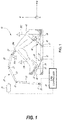
- a computer-assisted surgery (CAS) system is generally shown at 10, and is used to perform orthopedic surgery maneuvers on a patient, including pre-operative analysis of range of motion and implant assessment planning, as described hereinafter.
- the system 10 is shown relative to a patient's knee joint in supine decubitus, but only as an example.
- the system 10 could be used for other body parts, including non-exhaustively hip joint, spine, and shoulder bones.
- a particular function of the CAS system 10 is assistance in planning soft tissue balancing, whereby the CAS system 10 may be used in total knee replacement surgery, to balance tension/stress in knee joint ligaments.
- the CAS system 10 is utilized to collect soft-tissue tension data through controlled manipulation of the target joint with measurements collected using sensors embedded in various parts of the system.
- the CAS system 10 may be robotized, in which case it may have a robot arm 20, a foot support 30, a thigh support 40 and a CAS controller 50.
- the robot arm 20 is the working end of the system 10, and is used to perform bone alterations as planned by an operator or the CAS controller 50 and as controlled by the CAS controller 50.
- the foot support 30 supports the foot and lower leg of the patient, in such a way that it is only selectively movable.
- the foot support 30 may be robotized in that its movements may be controlled by the CAS controller 50.
- the thigh support 40 supports the thigh and upper leg of the patient, again in such a way that it is only selectively or optionally movable.
- the thigh support 40 may optionally be robotized in that its movements may be controlled by the CAS controller 50.
- the CAS controller 50 controls the robot arm 20, the foot support 30, or the thigh support 40.
- the CAS controller 50 may perform a range-of-motion (ROM) analysis and implant assessment in pre-operative planning, with or without the assistance of an operator.
- the CAS controller 50 may also guide an operator through the surgical procedure, by providing intraoperative data of position and orientation and joint laxity boundaries, as explained hereinafter.
- the tracking apparatus 70 may be used to track the bones of the patient, and the robot arm 20 when present. For example, the tracking apparatus 70 may assist in performing the calibration of the patient bone with respect to the robot arm, for subsequent navigation in the X, Y, Z coordinate system.
- the robot arm 20 may stand from a base 21, for instance in a fixed relation relative to the operating-room (OR) table supporting the patient.
- the OR table may consist of a 'U'-shaped end portion with each side of the 'U' supporting a leg of the patient and an open floor space existing between each leg.
- the base is positioned in the open floor space between the legs, therefore allowing the robot arm to access each leg of the patient without repositioning the base as would be desired in a bilateral total knee replacement procedure.
- the relative positioning of the robot arm 20 relative to the patient is a determinative factor in the precision of the surgical procedure, whereby the foot support 30 and thigh support 40 may assist in keeping the operated limb fixed in the illustrated X, Y, Z coordinate system.
- the robot arm 20 has a plurality of joints 22 and links 23, of any appropriate form, to support a tool head 24 that interfaces with the patient.
- the arm 20 is shown being a serial mechanism, arranged for the tool head 24 to be displaceable in a desired number of degrees of freedom (DOF).
- DOF degrees of freedom
- the robot arm 20 controls 6-DOF movements of the tool head 24, i.e., X, Y, Z in the coordinate system, and pitch, roll and yaw. Fewer or additional DOFs may be present.
- joints 22 and links 23 are powered for the robot arm 20 to move as controlled by the controller 50 in the six DOFs. Therefore, the powering of the joints 22 is such that the tool head 24 of the robot arm 20 may execute precise movements, such as moving along a single direction in one translation DOF, or being restricted to moving along a plane, among possibilities.
- Such robot arms 20 are known, for instance as described in United States Patent Application Serial no. 11/610,728 , incorporated herein by reference.
- the thigh support 40 may be robotized, static or adjustable passively. In the latter case, the thigh support 40 may be displaceable relative to the OR table, in order to be better positioned as a function of the patient's location on the table. Accordingly, the thigh support 40 is shown as including a passive mechanism, with various lockable joints to lock the thigh support 40 in a desired position and orientation.
- the mechanism of the thigh support 40 may have a slider 41, moving along the OR table in the X-axis direction. Joints 42 and links 43 may also be part of the mechanism of the thigh support 40, to support a thigh bracket 44.
- a strap 45 may immobilize the thigh/femur in the thigh support 40.
- the thigh support 40 may not be necessary in some instances. However, in the embodiment in which the range of motion is analyzed, the fixation of the femur via the thigh support 40 may assist in isolating joint movements.
- the CAS controller 50 is shown in greater detail relative to the other components of the robotized surgery system 10.
- the controller 50 has a processor unit to control movement of the robot arm 20, and of the leg support (foot support 30 and thigh support 40), when applicable.
- the robotized surgery controller 50 provides computer-assisted surgery guidance to an operator, whether in the form of a range-of-motion (ROM) analysis or implant assessment in pre-operatively planning or during the surgical procedure.
- the system 10 may comprise various types of interfaces, for the information to be provided to the operator.
- the interfaces may be monitors or screens including wireless portable devices (e.g., phones, tablets), audio guidance, LED displays, among many other possibilities. For example, there is illustrated in FIGS.
- GUI graphic user interfaces
- the controller 50 may then drive the robot arm 20 in performing the surgical procedure based on the planning achieved pre-operatively.
- the controller 50 may do an intra-operative soft-tissue balancing assessment, and hence enable corrective plan cuts to be made, or guide the selection of implants or other intra-operative adjustments to the plan.
- the controller 50 may also perform a post-operative ROM analysis.
- the controller 50 may hence have a robot driver 51, such as when the robot arm 20 is part of the CAS system 10.
- the robot driver 51 is tasked with powering or controlling the various joints of the robot arm 20, foot support 30 and thigh support 40, when applicable.
- the system may include some force feedback provided by the robot arm 20 and leg support 30,40 to avoid overextending the leg or damaging the soft tissue, and to assist in determining joint laxity boundaries.
- the robot driver 51 may control the foot support 30 in performing particular motions, to replicate a flexion/extension of the knee, with lateral movements, to measure soft tissue tension and analyze the range of motion of the leg, including varus/valgus.
- the robot driver 51 may output the instant angle of flexion using the position or orientation data it uses to drive the movement of the foot support 30.
- Sensors A are provided on the foot support 30 or in the robot arm 20 in order to measure throughout the movement the forces indicative of the tension/stress in the joint. The sensors A must therefore be sensitive enough to detect soft tissue tension/stress through the movement of the foot support 30. In the case of the robot arm 20, the sensors A may be force-torque sensors integrated therein.
- the CAS controller 50 may use a processor to implement force measurement 52.
- Force measurement 52 may include receiving the signals from the sensors A, and calculating the instant forces in the foot support 30, representative of the tension/stress in the knee joint, or in the robot arm 20, as exemplified hereinafter.
- the instant forces may be used to perform ROM analysis 53 using the processor, along with the foot support tracking data from the robot driver 51.
- the ROM analysis 53 may use tracking data received from the tracking device 70 to determine the range of motion of the leg, as explained hereinafter.
- the ROM analysis 53 may convert the signals from the tracking device 70 into position or orientation data. In the latter case, various types of tracking technology may be used to determine the instant flexion/extension and varus/valgus, such as optical tracking as illustrated in FIG.
- the ROM analysis 53 may be performed. Exemplary formats of the ROM analysis 53 are shown in FIGS. 5A-7B and in FIGS. 8A-8F , described hereinafter.
- the information of the ROM analysis 53 may therefore be a pre-operative indication of the current varus/valgus as a function of flexion/extension.
- the ROM analysis 53 may be performed intraoperatively, or post-operatively, to assist in quantifying the soft tissue balancing during or resulting from surgery.
- the processor may be used to perform an implant assessment 54 to determine how an implant or implants will impact the range of motion.
- the implant assessment 54 takes into consideration the geometrical configuration of the implants based on selectable locations on the bone.
- the implant assessment 54 may include the bone models B from pre-operative imaging (e.g., MRI, CT-scans, 2D X-ray to 3D), whether in 3D or in multiple 2D views.
- the implant assessment 54 may include the implant models C, such the 3D model files including implants of different dimensions.
- the implant assessment 54 may be performed in a fully automated manner by the processor, in evaluating from the bone model, implant models or from the ROM analysis 53 desired implant sizes and location on the bone (i.e., in position and orientation), to balance soft tissue tension/stress. Exemplary formats of the implant assessment are shown in FIGS. 9A and 9B for example, described hereinafter.
- the information of the implant assessment may therefore be a pre-operative or intraoperative indication of an anticipated post-surgical varus/valgus as a function of flexion/extension.
- the implant assessment 54 may optionally include operator participation.
- the illustrations of FIGS. 9A and 9B may be GUI items, such as in GUI 130, that may be adjusted virtually manually by an operator, for the operator to see the impact on the graphs of FIGS. 6B and 7B , respectively.
- the implant assessment 54 may provide the assessment to assist the operator in making a decision, as opposed to automatically proposing the desired implant sizes and location on the bone.
- the proposal of desired implant sizes and location on the bone may be a starting point of operator navigation or decision making.
- the implant assessment 54 may produce the output D in any appropriate format, such as GUIs 130.
- the format may also be that of FIGS. 11A and 11B , providing an assessment of the proposed implant sizes and location.
- the output D may also include bone alteration data to assist the operator or the robot arm 20 in performing the bone alterations.
- the processor may perform a resurfacing evaluation 55 to calculate the bone cut volume and location, for the bone cuts that will be made based on the implant sizes and location on the bone.
- the implant assessment 54 may also generate and respond to the GUI items illustrated in GUI 400 illustrated in FIGS. 11A - 11E .
- GUI 400 provides an operator, such as a surgeon or surgical assistant, with the ability to adjust implant position, orientation, and size as well as parameters associated with the spacer size selection.
- the GUI 400 is designed to provide quick assessment of soft-tissue balance based on selected implant parameters. Further aspects of how the implant assessment 54 operates with respect to examples GUI 400 are discuss below in reference to FIGS. 11A - 12 .
- the use of the tracking apparatus 70 may be determinative on the information that will be in the navigation file C, and may provide tracking data to perform the ROM analysis 53.
- the tracking apparatus 70 may assist in performing the calibration of the patient bone with respect to the robot arm 20, for subsequent navigation in the X, Y, Z coordinate system.
- the tracking apparatus 70 comprises a camera that optically sees and recognizes retro-reflective references 71A, 71B, and 71B, so as to track the limbs in six DOFs, namely in position and orientation.
- the reference 71A is on the tool head 24 of the robot arm 20 such that its tracking allows the controller 50 to calculate the position or orientation of the tool head 24 and tool 26A thereon.
- references 71B and 71C are fixed to the patient bones, such as the tibia for reference 71B and the femur for reference 71C.
- the references 71 attached to the patient need not be invasively anchored to the bone, as straps or like attachment means may provide sufficient grasping to prevent movement between the references 71 and the bones, in spite of being attached to soft tissue.
- the references 71B and 71C could also be secured directly to the bones. Therefore, the ROM analysis 53 of the controller 50 may be continuously updated to obtain a current position or orientation of the robot arm 20 or patient bones in the X, Y, Z coordinate system using the data from the tracking apparatus 70.
- the tracking system 70 may consist of inertial sensors (e.g., accelerometers, gyroscopes, etc.) that produce tracking data to be used by the controller 50 to continuously update the position or orientation of the robot arm 20.
- inertial sensors e.g., accelerometers, gyroscopes, etc.
- Other types of tracking technology may also be used.
- the calibration may be achieved in the manner described above, with the robot arm 20 using a registration pointer on the robot arm 20, and with the assistance of the tracking apparatus 70 when present in the robotized surgery system 10.
- Another calibration approach is to perform radiography of the bones with the references 71 thereon, at the start of the surgical procedure.
- a C-arm may be used for providing suitable radiographic images.
- the images are then used for the surface matching with the bone model B of the patient. Because of the presence of the references 71 as fixed to the bones, the intraoperative registration may then not be necessary, as the tracking apparatus 70 tracks the position or orientation of the bones in the X, Y, Z coordinate system after the surface matching between X-ray and bone model is completed.
- the robotic arm 20 may apply force to a soft tissue balancing component using an end effector component or a detachable pin guide component locked to the end effector component.
- the soft tissue balancing component (e.g., as described in further detail below, for example in the discussion of FIGS. 3 , 4 , and 10A-10D ) may apply force in turn to a bone or implant component to test or configure soft tissue balance. More generally, the soft tissue balancing component may be used to perform a ligament balance pull test. Based on the pull test, a femoral rotation may be determined. The femoral rotation may be presented (e.g., using a graphical user interface, such as those described below in the discussion of FIGS. 8A - 11E ).
- the femoral implant rotation may be used to calculate a target femoral implant rotation.
- the target femoral implant rotation may be displayed (e.g., using a user interface, such as those described below in the discussion of FIGS. 10A - 11E , for example).
- the target femoral implant rotation may be an inverse or opposite of the rotation of the femur rotation. For example, when the femur rotation is 3 degrees internally, the target femoral implant rotation may be 3 degrees external from the femur.
- the target femoral implant rotation may be further adjusted as well.
- the femoral implant rotation may be determined such that the rotation may compensate for an imbalance in soft tissue tension between medial and lateral compartments.
- the rotation of the femur during the pull test may be directly related to the determined femoral implant rotation such that a rectangular or balanced gap results from applying the rotation. For example, when the rotation is applied to placement of the implant, the gap may be balanced between the medial and the lateral compartments.
- the robotic arm 502 may apply a force to perform the pull test by using the soft tissue balancing component to pull on the femur. To perform the test, the robotic arm 20 may apply one or more known loads to increase the accuracy of the determined rotation.
- a torque or force sensor may be used to measure torque of one or more of the components, such as the robotic arm 20, the tool head 24, or on a component such as a soft tissue balancing component.
- a sensor may be used to detect ligament stress or ligament tension.
- a position or orientation sensor e.g., a navigation sensor, such as a sensor located on a portion of the robotic arm 20
- a varus or valgus angle may be used to determine ligament pulling in the target leg.
- pulling on the soft tissue may be determined and a rotation to correct the pulling may be determined, and may be output on a graphical user interface (GUI), such as that described with respect to FIGS. 10A - 11E .
- GUI graphical user interface
- a ligament test or other soft tissue balancing test may be performed before a bone resection cut is performed.
- the soft tissue balancing test may be performed before any resection of a femur or a tibia.
- the soft tissue balancing test may be performed after resection and implantation of an implant to verify that the soft tissue is correctly balanced.
- a first test may be performed pre-resection, which may result in a rotation angle to be used for balancing, and a second test may be performed after the implant is inserted to verify that the rotation angle was correct or that the implant was properly seated.
- the CAS controller 50 may operate the robot arm 20 to perform a robotized soft-tissue balancing assessment, such as by using a processor to perform soft-tissue balancing 56, although it may also be done without robotized assistance.
- a robotized soft-tissue balancing assessment such as by using a processor to perform soft-tissue balancing 56, although it may also be done without robotized assistance.
- the robot arm 20 may be driven to pull on the bone and hence put the soft tissue under tension. Applied tension may be controlled using the signals from the force-torque sensors A in the robot arm 20 with the output of the force measurement 52.
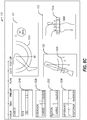
- the device 80 includes a pin and a cutting block.
- the robot arm 20 may pull the femur away from the tibia by manipulating the pin of the device 80, such that the pin (and femur) may rotate relative to the robot arm 20.
- the rotation of the femur will naturally go toward soft tissue balancing, in which tension T1 is equal to tension T2.
- the device 80 may further include an inertial sensor to measure a rotation ⁇ indicative of the rotation required for soft tissue balancing.
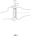
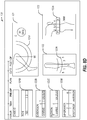
- the rotation ⁇ may also be monitored and measured by the robot arm 20, with appropriate sensors (optical, encoders, inertial, etc.). Referring to FIG. 4 , similar operations may be performed with the leg being in extension.
- FIG. 4 similar operations may be performed with the leg being in extension.
- the robot arm 20 may pull the femur away from the tibia, either in extension or in flexion, and automatically stop.
- the robot arm 20 may stop for example at a predetermined distance (gap), when a threshold force or tension is reached, or at a user-selected stopping position.
- the predetermined distance e.g., 5mm, 10mm, a distance corresponding to a tibia implant thickness such as 10mm, 11mm, 12mm, etc.
- a combination of end position markers may be used, such as a predetermined distance approximately equal to a tibia implant thickness (e.g., an insert (poly) or the implant assembly, which may be predetermined using planning techniques), while retaining a maximum force as safety factor. For example, when a maximum force is reached before the predetermined distance, the robotic arm may be stopped. In another example, balanced ligaments may be used to mark the end position.
- the soft tissue is put under tension using a robot arm, such as the robot arm 20 (not shown), acting on the device 80.
- the robot arm 20 raises the device 80 to displace the femur, while the tibia remains still by gravity or by its fixation to the table (e.g., when a foot support 30 is used), by a human (e.g., surgical assistant or the surgeon), by surgical tape, self-adherent wrap or tape, or other fixing devices or components to secure the tibia.
- laminar spreaders on the robot arm 20 to spread the bones apart. The laminar spreaders may be inserted in the gap between the femoral condyles and the tibial plateau.
- the spreaders may manipulate a clamp to benefit from the leveraging of the clamp to apply a greater moment at the bones.
- the spreaders may manipulate a spreader with gear mechanism (planetary gear device, rack and pinion, etc.), to assist in amplifying the force of the robot arm.
- gear mechanism planetary gear device, rack and pinion, etc.
- the processor may perform soft-tissue balancing 56 to quantify joint laxity to assist in the soft-tissue balancing at different moments during the surgical procedures operated by the CAS controller 50.
- the soft-tissue balancing 56 may assess soft-tissue balancing prior to having the robot arm 20 perform the alterations to the bone, to confirm the desired implant sizes and location on the bone produced by the implant assessment 54, or to enable adjustments to the desired implant sizes and location on the bone, and impact the output of the resurfacing evaluator 55.
- the soft-tissue balancing 56 may assess soft-tissue after cut planes have been made, to determine whether further adjustments are necessary.
- the output D is in the form of a patient-specific cut guide 3D file, for a patient-specific cut guide to be machined or 3D printed for operative use.
- the patient-specific cut guide may have negative surfaces of the bone model for unique positioning on the bone, such that cut planes and drill guides are placed as planned.
- the output D may be a navigation file, of the type programmed into inertial sensor units manually navigated by an operator. Referring to FIG. 4 , similar operations may be performed with the leg being in extension.
- the soft tissue assessment may be performed with the leg in flexion (e.g., as shown in FIG. 3 ) or in extension (e.g., as shown in FIG. 4 ).
- the leg When in flexion, the leg may be held at a 90 degree angle of flexion, or substantially 90 degrees, such as within plus or minus ten degrees.
- the leg With the leg in extension, the leg may be held at zero degree angle of extension, 10 degrees, 20 degrees, or the like, such as based on surgeon preference.
- the soft tissue assessment may be used to measure or display gap measurements for soft tissue balancing during a test when a knee is in flexion or extension.
- the soft tissue balancing assessment when the knee is in flexion may include not releasing the femur when pulling.
- the test may include pulling on the femur, then measuring an amount of rotation that results in balance between the soft tissue (e.g., ligaments).
- the femur may be free to rotate to find the balance based on the amount of force on the ligaments.
- the soft tissue balancing assessment may be performed with the patella in place or dislocated. Additional examples of robotic soft-tissue balancing are discussed in detail within Application Serial No. 15/624,621 .
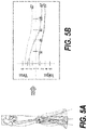
- FIGS. 5A and 5B are user interfaces for displaying a range-of-motion (ROM) analysis of a CAS controller in accordance with some embodiments.
- FIGS. 6A and 6B are user interfaces for displaying an implant assessment of a CAS controller, enabling implant movement from a caudal viewpoint in accordance with some embodiments.
- FIGS. 7A and 7B are user interfaces for displaying an implant assessment of a robotized surgery controller, enabling implant movement from a frontal viewpoint in accordance with some embodiments.
- FIG. 5B a graph illustrating an actual varus/valgus balanced line 60 as a function of the leg extension is shown, as a result of the controlled movements of the foot support 30.
- the force measurement data allows the positioning of 60, as an indication of the varus/valgus value at balanced soft tissue.
- Lines 61 and 62 respectively show the valgus and varus values at maximum allowable soft tissue tension, as a result of the lateral movements depicted in FIG. 5A , as measured by the force measurement 52.
- the graph of FIG. 5B is the ROM analysis, done preoperatively or post-operatively.
- a similar graph may be produced by the implant assessment 54, to illustrate the impact of given implants at a given location on the bones.
- the model of the implant I may be rotated by an operator, with angle values being instantly updated.
- the varus/valgus balanced line 60 may shift to reduce the valgus as in 60A ( FIG. 6B ) or to reduce the varus as in 60B ( FIG. 7B ).
- An operator or a processor performing the implant assessment 54 may therefore perform such adjustment in order to bring the balanced line 60 closer to a neutral varus/valgus through as much of the leg extension as possible.
- GUI is used in the plural to indicate a variation of GUI pages in the surgical workflow.
- the surgical workflow may be the output D produced by the processor of the CAS controller 50.
- the descriptions of the following GUI may omit certain operations necessary to perform any particular arthroplasty, and are intended solely to highlight techniques used in certain aspects of certain surgical procedures.
- GUI 120 is used to guide the gathering of range-of-motion data of the tracked limbs, tracked in a virtual coordinate system by a tracking system, such as tracking device 70.
- the GUI 120 guides a human operator, such as a surgeon or medical professional, in determining the limits of the range of motion and of joint laxity, based on force felt by the operator, as an alternative to using the force feedback capability of the robotized version of the system 10.
- a lateral leg display 121 may be provided to visually illustrate the limits of flexion and extension, with related angle.
- the operator manually displaces the tibia relative to the femur between maximum (flexion) and minimum (extension) angles, and the tracking of the tibia and femur by the tracking device 10 allows the processor to record these angles for use in the ROM analysis 53.
- the operator may assist in determining the maximum and minimum angle, by judging when to stop the extension and flexion based on the resistance felt.
- the leg display 121 may present the measured data in different forms, using for instance a movement arch 121A to visually show the range of movement.
- a ROM bar 121B may also be provided, showing the numerical values of angle, including a median angle.
- a frontal leg display 122 may also be provided in GUI 120 to visually illustrate the varus/valgus angles at extension and flexion.
- the operator manually extends the leg, to then pivot the tibia relative to the femur to maximum varus and valgus angles, and the tracking of the tibia and femur by the tracking device 70 allows the ROM analysis 53 to use these angles.
- the maximum varus/valgus angles may be determined by the operator's judgement as to when to stop the extension and flexion based on the resistance felt.
- the frontal leg display 122 may provide the data in different forms, using also for example a movement arch 122A to visually show the range of movement, and an extension varus/valgus bar 122B, showing the numerical values of varus and valgus.
- a flexion varus/valgus bar 122C may then show the numerical values of varus and valgus. These values are recorded for subsequent use by the processor in performing the soft tissue balancing 56. Moreover, these values may indicate a loose or tight knee condition, laterally or medially, whether it be correctable by implant positioning or not. In the latter case, the system 10 may suggest ligament releasing to remedy the condition.
- the soft tissue balancing 56 may identify such a condition by being programmed with acceptable varus/valgus angle ranges.
- the varus/valgus angles obtained may be representative of the laxity of the medial and of the lateral collateral ligaments, as these ligaments delimit knee laxity.
- these ligaments may also affect laxity.
- the knee articular capsule and the patellar tendon may also affect joint laxity.
- an enlarged joint display 123 may also be provided to visually illustrate the anterior and posterior drawer distances at flexion.
- the operator manually pushes and pulls the tibia relative to the femur to maximum posterior and anterior positions, and the tracking of the tibia and femur by the tracking device 70 allows the ROM analysis 53 to use the drawing positions, relative to a neutral position at which the tibia is natively positioned relative to the femur by soft tissue tension.
- the maximum distances may be determined by the operator's judgement as to when to stop the pushing and pulling based on the resistance felt.
- the joint display 123 may have different forms, using a distance scale 123A to visually show the range of movement, and a distance bar 123B, showing the numerical values of varus and valgus. These values are recorded for subsequent use during the soft tissue balancing 56.
- Joint displays 123A and 123B may also indicate a target laxity (for comparison) which is programmed to reflect the ideal laxity.
- the ideal laxity may be based on a surgeon-defined preference or suggested value from literature.
- the system 10 has recorded joint laxity data.
- the recorded information may be based on force feedback felt by the surgeon manipulating the tibia relative to the femur, or may be the result of manipulations by robotized components using sensors A and output by the force measurement 52 when the robotized components are programmed to limit force values.
- the recorded range of motion and joint laxity information may include maximum flexion angle, maximum extension angle, range of motion, varus and valgus angle values at extension, at flexion, or at any desired angle, anterior drawer distance, posterior drawer distance.
- the recorded information may be as a function of 3D bone models B of the tibia and femur, or of other bones in different surgical procedures. The order of information gathering using the GUI 120 may be changed from the order described above.
- FIGS. 8E-8F illustrate some additional pre-operative graphical user interfaces (GUIs) 220A and 220B, which may be used for displaying flexion/extension angle, gaps, varus and valgus angles of a knee in accordance with some embodiments.
- the GUIs 220E and 220F include a video component 228 to display real-time range of motion.
- the GUIs 220E and 220F include one or more graphical information components. For example, GUI 220E shows the varus/valgus angle 226 at 6 degrees varus in the medial direction at a flexion angle 224 of 50 degrees (from full extension at 0 degrees).
- GUI 220F shows the varus/valgus angle 226 at 5 degrees varus in the medial direction at a flexion angle 224 of 59 degrees (from full extension at 0 degrees). Additional information is shown at graphical information component 222 in the GUIs 220E and 220F.
- the graphical information component 222 includes gap information, varus/valgus angle information, range of motion information, and extension/flexion information. The range of motion information may be used to create a preoperative plan.
- one or more of the GUIs 220E or 220F may provide a remote video or allow for a remote audio connection, such as with a remote surgeon.
- the remote video or remote audio may be a real-time connection to allow the remote surgeon to discuss a procedure or provide training with a local surgeon or to monitor the local surgeon.
- a GUI used by the remote surgeon may provide the remote surgeon with a video display of a surgical field operated by the local surgeon.
- GUI 130 is used for the planning of the implant positions and orientations, taking into consideration joint laxity and range of motion as obtained using GUI 120.
- the GUI 130 receives output from the implant assessment 54 and from the soft tissue balancing 56.
- the GUI 130 may have a joint display 131 showing bone models B with implant models C.
- the joint display 131 may include a view of the knee in extension ( FIG. 9A ) and a view of the knee in flexion ( FIG. 9B ).
- the user of GUI 130 may toggle between flexion and extension views, and may also toggle between frontal ( FIGS. 9A and 9B ), sagittal or axial planes of view, on preference.
- the initial or proposed location of the implant models C relative to the bone models B may be determined by the implant assessment 54 using the joint laxity data output by the soft tissue balancing 56.
- the current location may be quantified using different markers, such as those described below.
- Joint-line variation plane 131A may display the pre-operative joint line versus the proposed joint line or the current joint line (i.e., actual location, as modified) when an operator varies the location of either one of the implant models C.
- Lateral laxity scale 132A and medial laxity scale 132B may provide a visual indication of the acceptable lateral and medial soft tissue tension. In FIGS. 9A and 9B , the acceptable range is indicated by upper and lower limits, along with a pointer indicating the tension at the current implant locations.
- the scales 132A and 132B may also provide gap distances, current femur and tibia varus/valgus angles, and an anterior gap for patellofemoral joint stuffing as additional data representative of joint laxity.
- the gap distances may be the sum of planned resection and ligament laxity compared to implant thickness.
- the laxity scales 132A and 132B dynamically reflect modifications to the planned implant location. The adjustments to implant location reflected on the laxity scales 132A and 132B may also be reflected by changes in the graphs shown in FIGS. 6B and 7B , as a function of a rotation of the implant.
- a femoral component window 133 may enable the change of femoral implant size.
- the user may have the possibility of changing implant sizes, in which case the displayed femoral implant model and related information on the joint display 131 may be updated (131A, 132A, 132B, etc.).
- a spacer component window 134 may enable the selection of the spacer thickness or the type of spacer. Changes to the spacer component may result in a dynamic update of the joint display 131 and of related data (131A, 132A, 132B, etc.).
- a tibial component window 135 may enable the change of tibial implant size, with the user given the option of changing implant sizes, in which case the displayed tibial implant model and related information on the joint display 131 may be dynamically updated (131A, 132A, 132B, etc.).
- a location control panel 136 is provided for the user to modify the location of the femoral component relative to the femur, in translation or location. As the location is modified using the location control panel 136, the joint display 131 may be updated and applicable data is also adjusted, such 131A, 132A, 132B, etc.
- the implants in the joint display 131 may be widgets that may be moved around relative to the bone models B, with the consequential dynamic adjustment of applicable data (e.g., 131A, 132A, 132B).
- the widget feature may be available in all views. It has the same function whether it is overlaid on the knee or on the left panel of GUI 130: it allows the user to position/orient the implant with respect to the bone. The effect of changing position or orientation of the implant will be dynamically reflected in the laxity scales.
- the laxity scales will be different in flexion and extension.
- the laxity scales could be provided throughout all angles of flexion.
- the processor may perform the implant assessment 54 or the soft tissue balancing 56, and may propose implant components and locations for the implant components via the GUI 130.
- the GUI 130 gives the possibility to an operator to modify the implant components or their locations, by dynamically updating in real-time quantitative data related to joint laxity and range of movement, to assist the operator is finalizing the resection planning.
- the information of the GUI 130 is converted into another form of the output D, such as personal surgical instrument tool files or data to perform resection as decided, a navigation file for the robot arm 20 when present, or a navigation file for tracked tools.
- the GUI 130 may also be used post-resection, to provide the joint laxity data for the "as-resected" state. The data may be used to document the surgical procedure. This may also allow post-resection corrections when deemed necessary. It may be required to return to GUI 100 or 110 to recalibrate the bones to obtain more precision in the assessment.
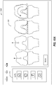
- FIGS. 10A-10D illustrate example user interfaces 330A-330D for joint replacement surgical planning in accordance with some embodiments.
- User interface 330A of FIG. 10A includes a cut checklist 332 to illustrate cuts that have been performed or that are not yet completed.
- User interface 330A includes an interactive user guide 334 showing a soft tissue balancing test overview.
- the user guide 334 shows a target implant rotation with respect to a femur to give a balanced flexion gap.
- the user guide 334 shows four steps of the soft tissue balancing test, from an initial state, to pulling on the femur, to showing a gap imbalance, to finally showing a rotation to align the soft tissue.
- User interface 330B of FIG. 10B includes a second user guide 336 including instructions on how to insert a spike 3308 to connect a soft tissue balancing component 3310 to a femur 3312.
- the spike 3308 holds the soft tissue balancing component 3310 in place, but may allow the femur 3312 to rotate.
- the soft tissue balancing test may be initiated, for example, by pressing a foot pedal, which is indicated in the second user guide 336.
- the soft tissue balancing test may be performed with a patella or soft tissue in place by using a j-shaped or hook-shaped soft tissue balancing component 3310.
- a robotic arm may pull the soft tissue balancing component 3310, such as by using an end effector connecting the robotic arm to the soft tissue balancing component 3310 to apply a force on the spike 3308, which may in turn cause a force on the femur 3312, for example to move the femur 3312 away from a tibia.
- User interface 330C of FIG. 10C includes a third user guide 340 which shows an illustration of a patient joint including a current imbalance at a particular gap distance, while superimposing a proposed balance (e.g., based on completed releases, cuts, and implants added to the joint).
- the third user guide 340 includes information related to a current rotation or a target femoral implant rotation (e.g., the rotation information may change over time or during a procedure, such as from a current rotation to a target rotation, or may show both, or a difference).
- the distance pulled e.g., over time or at a current time
- the third user guide 340 may include user-selectable options to apply a target femoral implant rotation to a 3D plan or to not apply the target femoral implant rotation to the 3D plan.
- the 3D plan may include preoperative or intraoperative plans. Adding the target femoral implant rotation to the 3D plan may include adding it to the 3D plan as is, or with changes (e.g., surgeon adjustments).
- the user guide 340 may include a force bar 3313 or a distance bar 3315.
- the force bar 3313 may be used to display a current pulling force (e.g., of a robotic arm on the femur).
- the robotic arm may be stopped automatically by a robotic controller when the force reaches a maximum force, which may be displayed on the force bar 3313.
- a surgeon may control the robotic arm by adjusting the force bar 3313.
- the distance bar 3315 may move simultaneously with the force bar 3313 in an example.
- the distance bar 3315 shows a distance pulled, such as a distance from the femur to the tibia (whether the femur or the tibia is pulled).
- the distance bar 3315 may be controlled by a surgeon to move the robotic arm similar.
- the distance bar 3315 may include a maximum distance pulled, which when the femur and the tibia are separated by the maximum distance, the robotic arm may be stopped.
- User interface 330D of FIG. 10D includes a fourth user guide 342, which shows rotation of a femur in a knee joint in various views.
- the femur may be viewed in flexion with respect to a tibia or in extension.
- the user guide 342 may be automatically updated (e.g., using trackers).
- One or more of user guides 334, 336, 340, or 342 may include information on ligament balance. For example, a soft tissue balancing test may be performed, and force information, tension information, or other sensor data may be sent to the one or more of user guides 334, 336, 340, or 342 to display soft tissue balance, such as a rotation angle to balance the ligaments.
- the one or more of user guides 334, 336, 340, or 342 may display a measured resection technique, for example by providing feedback on actual measured angles or detected forces after or before resection, in addition to the rotation angle at which there is balance.
- medial and lateral borders of a tibial tubercle may be identified and used to determine a medial third landmark location.
- the one or more of user guides 334, 336, 340, or 342 may display the medial and lateral borders or the medial third landmark location.
- a robotic arm may be used to identify a most medial boundary of a tibial tuberosity.
- the robotic arm may be used to identify a most lateral boundary of the tibia tuberosity.
- a system may use these identified boundaries to accurately display and locate a location known as a medial third location on the tibial tuberosity. Identifying this location may not be reproducibly performed with conventional instrumentation, such as with sub-millimeter metric precision. This location may be used to assist in a rotational placement of a tibial base plate for a knee arthroplasty as a reference point.
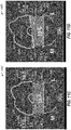
- FIGS. 11A-11E illustrate graphic-user interfaces (GUI) for soft-tissue balancing and implant placement in accordance with some embodiments.
- the user guides 400A-400B (collectively referred to as GUI 400) provide an alternative interface for selecting implant location and orientation as well as a graphical representation of soft-tissue balance based on implant size, orientation, and location.
- the GUI 400 includes a soft-tissue section 425 (425A-425E, collectively referenced as soft-tissue section 425) that provide a surgeon or surgical assistance an informative view of a predicted condition of the joint (a knee joint in the examples illustrated).
- the soft-tissue section 425 can include a trapezoidal graphic 430 (trapezoidal graphic 430A-430E, collectively referenced as trapezoidal graphic 430) positioned between graphics representing a distal femur 426 and proximal tibia 427.
- the trapezoidal graphic 430 is an interactive element that updates in response to inputs adjusting parameters such as implant position (medial-lateral, anterior-posterior), implant orientation (varus/valgus rotation), and spacer size selection, which can all be a function of or affect soft-tissue tension and/or balance in the joint.
- the trapezoidal graphic 430 is designed to reproduce what the surgeon is seeing within the joint under reconstruction, while overlaying quantitative information, such as gap distance (medial-lateral), cut depths (medial-lateral), laxity measurements (medial-lateral), distal femur resection angle, posterior femoral resection angle, proximal tibia resection angle, and spacer size representation.
- the trapezoidal graphic 430 does not specifically illustrate a proximal tibia resection angle, but this can be displayed in a manner similar to the distal femur resection angle.
- the bottom line of the joint gap indicator 432A can include an angled portion to indicate an angle of the proximal tibial resection.
- the GUI 400A includes a surgical procedure guide 405, a size selection interface 410, a system menu 415, an implant positioning section 420, a soft-tissue section 425A, flexion/extension control 442, display control 444, a bone view control 446, a trapezoid control 448, a tracking system control 450, and home control 455.
- the joint is illustrated in extension with the flexion/extension control 442 highlighting the extension selection.
- the implant positioning section 420 can include a position control 422 that enables the surgeon to adjust medial-lateral and anterior-posterior position of the implant.
- the implant positioning section 420 can also include an orientation control 423, which enables the surgeon to adjust varus/valgus angle of the implant.
- the implant positioning section 420 can also include various numeric or textual readouts to provide the surgeon with quantitative information related to the surgical procedure based on the current implant position.
- the quantitative information displays include distal resection amount and proximal resection amount on both the medial and lateral sides.
- the example can also include medial and lateral posterior resection measurements (with flexion selected in the flexion/extension control 442).
- the implant positioning section 420 in this example, includes readouts for varus/valgus angles for femur and tibia.
- the position control 422 and orientation control 423 is illustrated over the femoral component, but can also be activated for the tibial component via selection of the tibial component.
- soft-tissue section 425A includes distal femur graphic 426, proximal tibia graphic 427, trapezoidal graphic 430A, balance angle indicator 431A, joint gap indicator 432A, resection angle indicator 433A, medial laxity indicator 434A, lateral laxity indicator 435A, medial gap data 436A, and lateral gap data 437A.
- the trapezoidal graphic 430A includes the balance angle indicator 431A, the joint gap indictor 432A, and the resection angle indicator 433A.
- the balance angle indicator 431A can provide a graphical representation of how soft tissue in the joint is balanced based on a calculated position and angle of a femoral resection based on a selected implant position and orientation.
- the resection angle indicator 433A graphically illustrates the angle of the distal femoral resection, which is related to the balance angle indicator 431A.
- the resection angle indicator 433A displays a resection angle of a posterior femoral resection.
- the resection angle indictor 433A can be color coded and/or displayed with a textual indication of angle.
- the joint gap indicator 432A graphically (and textually in this example) illustrates the common gap across the medial-lateral width of the joint.
- the joint gap indicator 432A provides an indication of the space available for implants and/or spacer components.
- the joint gap indicator 432A can illustrate and/or indicate a calculated spacer size, which may or may not also represent the common gap distance.
- Other components in the joint prosthesis will take up a portion of the total gap distance, such as the femoral component and the tibial tray.
- FIG. 11B illustrates another example GUI 400B with a modified collection of information displayed in the soft-tissue section 425B.
- the soft-tissue section 425B includes trapezoidal graphic 430B, medial laxity indicator 434B, lateral laxity indicator 435B, medial gap data 436B, and lateral gap data 437B.
- the trapezoidal graphic 430B includes joint gap indicator 432B, balance angle indicator 431B and resection angle indicator 433B as well as a textual display indicating the common gap distance across both medial and lateral side of the joint (19.0 mm in this example).
- the medial gap data 436 and lateral gap data 437B both include information such as Total Gap and Cut measurements.
- the medial laxity indicator 434B and the lateral laxity indicator 435B both include readouts indicating actual laxity measurement in addition to the Loose, Normal, or Tight indictors.
- FIG. 11C illustrates another example soft-tissue section portion of the GUI 400 discussed in the previous two figures.
- the knee joint is in flexion, which means the femoral resection displayed is a posterior resection.
- the soft-tissue section 425C can include trapezoidal graphic 430C, medial laxity indicator 434C, lateral laxity indicator 435C, medial gap data 436C, and lateral gap data 437C.
- the trapezoidal graphic 430C can include a joint gap indicator 432C, medial overlap indicator 439C and lateral overlap indicator 438C.
- the medial overlap indicator 439C provides a linear graphical display of the medial condyle overlap into the projected posterior femoral resection.
- the angle of the resection is not depicted, but rather a bar-graph type view of the overlaps of the condyles is shown instead.
- the lateral overlap indicator 438C depicts the lateral condyle overlap.
- the hashed portion of the medial overlap indicator 439C and lateral overlap indicator 438C illustrate the amount of laxity on each side of the joint illustrated in conjunction with the condyle overlap to assist in putting the laxity measurements into perspective in view of the planned resections.
- FIG. 11D illustrates another example soft-tissue section including a variation on the trapezoidal graphic with the knee joint in flexion.
- trapezoidal graphic 430D can include balance angle indicator 431D, joint gap indicator 432D, resection angle indicator 433D, lateral overlap indicator 438D and medial overlap indicator 439D.
- the lateral overlap indicator 438D and the medial overlap indicator 439D in this example are angled to coincide with the resection angle indicator 433D.
- the direction and coloring of the hashed portion of the lateral overlap indicator 438D and the medial overlap indicator 439D provide information on joint laxity.
- the lateral overlap indicator 438D is illustrated as being above the joint gap indicator 432D, which can indicate a loose portion of the joint.
- the hashed portion of the lateral overlap indicator 438D can be colored green if the looseness is considered acceptable or desirable.
- a different color may be utilized to indicate a loose joint, such as orange.
- the medial overlap indicator 439D is depicted as below the upper portion of the joint gap indicator 432D, and may be colored red to indicate a negative overlap or an undesirable condition.
- a different (more neutral) color may be associated with a negative overlap to indicate a tight joint section (especially where the tightness is not considered undesirable).
- the coloring in particular of these graphical displays can be configured to correspond to a surgeon's preferences in terms of joint laxity measurements.
- any tight indicator may always be colored red to assist in quick identification of an undesirable condition.
- Any of the soft-tissue sections discussed can utilize colored graphics and/or text to indicate positive, negative, or neutral conditions of a joint under reconstruction.
- the surgeon can program parameters of the GUI to conform to individual preferences for joint soft-tissue balance, resection depths, and spacer sizing, among other things.
- FIG. 11E illustrates another example soft-tissue section including a variation on the trapezoidal graphic.
- trapezoidal graphic 430E can include balance angle indicator 431E, joint gap indicator 432E, resection angle indicator 433E, lateral overlap indicator 438E and medial overlap indicator 439E.
- the lateral overlap indicator 438E and the medial overlap indicator 439E in this example are angled to coincide with the resection angle indicator 433D and a graphical representation of the posterior portions of the medial and lateral condyles is also included in the distal femur graphic 426.
- the medial laxity indicator 434E and the lateral laxity indicator 435E include Loose/Neutral/Tight indicators as well as total laxity measurements and measures of tightness or looseness.
- the medial laxity indicator 434E indicates a tight joint side with 2.0mm of total laxity and 2mm of tightness.
- the lateral laxity indicator 435E indicates a loose joint side with 2.5mm of total laxity and 1.5mm of looseness.
- the medial laxity indicator 434E may be color coded red to indicate tightness, which may also indicate that the displayed values are (or could be considered) negative numbers.
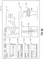
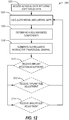
- FIG. 12 illustrates a flow chart showing a technique 1200 for analyzing soft-tissue balance and adjusting implant placement in accordance with some embodiments.
- the technique 1200 can include operations such as accessing surgical data at 1202, calculating gaps at 1204, determining components at 1206, generating the GUI at 1208, and optionally updating based on receiving inputs such as implant adjustment, implant size selection or spacer size adjustment.
- the technique 1200 can begin at 1202 with the controller 50 accessing surgical data including soft-tissue data.
- the soft-tissue data can include actual measurements of tension in a medial and a lateral side of joint.
- the soft-tissue data can also (or alternatively) include gap distance measurements taken when the joint is a particular position with a known tension or force applied.
- the soft-tissue data can be measurements performed with the knee in flexion with a known force applied to displace either the distal femur or the proximal tibia in a direction to extract the joint.
- soft-tissue measurements can be taken before or after initial resections of the distal femur and/or the proximal tibia.
- the technique 1200 can continue with the controller 50 calculating medial and lateral gaps based on the soft-tissue data received at operation 1202.
- the controller 50 utilizes tension measurements for the medial and lateral sides to estimate a gap distance for each side of the joint.
- the calculation of the gaps may involve resolving position data received from a robot or similar sensors to determine gap distances on the medial and lateral sides.
- the data used can include a distance and angle, where the distance is the distraction distance between the distal femur and proximal tibia and the angle is the measured angle of the proximal femur (in reference to the joint mechanical axis or the proximal tibia).
- the technique 1200 can continue with the controller 50 determining a recommended component set.
- the component (implant) set can include a femoral component, a tibial component, and a spacer.
- the component recommendation is determined, at least in part, based on the soft-tissue data as well as an understanding on the available component and spacer sizes within the implant system or kit. Component select is also impacted by additional factors, such as size of distal femur and proximal tibia, among other things. Spacer size selection takes into account the size of implant selected, when determining how best to fit the gap with a combination of femoral component, tibia component and spacer (when necessary).
- the component selection is also impacted by the target soft-tissue tension or laxity measurement.
- the parameters associated with component selection can be surgeon preference driven allowing individual preferences to be built into the automated recommendations.
- Certain components can be selected in advance, such as femoral component and/or tibial component, in these examples the spacer size is calculated to attain target soft-tissue balance.
- the technique 1200 can continue at 1208 with the controller 50 generating a GUI including an interactive trapezoidal graphic, such as trapezoidal graph 430.
- the trapezoidal graphic is generated to graphically illustrate soft-tissue and joint condition based on soft-tissue tension under circumstances predicted with selected implants and/or spacers.
- the trapezoidal graphic is interactive; in that it changes or updates as parameters of the implant or spacer are changed.
- the technique 1200 can optionally include at 1210 with the controller 50 receiving an implant position (or orientation) adjustment. Upon receipt of the implant position adjustment, the controller 50 returns to operation 1204 to recalculate and update the trapezoidal graphic at operation 1208.
- the technique 1200 can optionally include the controller 50 receiving an implant size adjustment, which also results in recalculation of the trapezoidal graphic at 1208. Finally, the technique 1200 can optionally include operation 1214 where the controller 50 can receive a spacer size adjustment and re-process data to re-generate the trapezoidal graphic at 1208.
- Method examples described herein may be machine or computer-implemented at least in part. Some examples may include a computer-readable medium or machine-readable medium encoded with instructions operable to configure an electronic device to perform methods as described in the above examples.
- An implementation of such methods may include code, such as microcode, assembly language code, a higher-level language code, or the like. Such code may include computer readable instructions for performing various methods. The code may form portions of computer program products. Further, in an example, the code may be tangibly stored on one or more volatile, non-transitory, or non-volatile tangible computer-readable media, such as during execution or at other times.
- Examples of these tangible computer-readable media may include, but are not limited to, hard disks, removable magnetic disks, removable optical disks (e.g., compact disks and digital video disks), magnetic cassettes, memory cards or sticks, random access memories (RAMs), read only memories (ROMs), and the like.
Landscapes
- Health & Medical Sciences (AREA)
- Engineering & Computer Science (AREA)
- Surgery (AREA)
- Life Sciences & Earth Sciences (AREA)
- Heart & Thoracic Surgery (AREA)
- Veterinary Medicine (AREA)
- Nuclear Medicine, Radiotherapy & Molecular Imaging (AREA)
- Biomedical Technology (AREA)
- Robotics (AREA)
- Medical Informatics (AREA)
- Molecular Biology (AREA)
- Animal Behavior & Ethology (AREA)
- General Health & Medical Sciences (AREA)
- Public Health (AREA)
- Human Computer Interaction (AREA)
- Prostheses (AREA)
- Surgical Instruments (AREA)
- Processing Or Creating Images (AREA)
Applications Claiming Priority (1)
| Application Number | Priority Date | Filing Date | Title |
|---|---|---|---|
| US15/853,657 US11229489B2 (en) | 2016-06-16 | 2017-12-22 | Soft tissue balancing in articular surgery |
Publications (3)
| Publication Number | Publication Date |
|---|---|
| EP3524200A2 true EP3524200A2 (de) | 2019-08-14 |
| EP3524200A3 EP3524200A3 (de) | 2019-08-28 |
| EP3524200B1 EP3524200B1 (de) | 2020-09-09 |
Family
ID=65033304
Family Applications (1)
| Application Number | Title | Priority Date | Filing Date |
|---|---|---|---|
| EP18215519.2A Active EP3524200B1 (de) | 2017-12-22 | 2018-12-21 | Weichteilbalancing in der gelenkchirurgie |
Country Status (2)
| Country | Link |
|---|---|
| EP (1) | EP3524200B1 (de) |
| AU (1) | AU2018282467B2 (de) |
Cited By (3)
| Publication number | Priority date | Publication date | Assignee | Title |
|---|---|---|---|---|
| CN111768494A (zh) * | 2020-06-28 | 2020-10-13 | 上海交通大学医学院附属第九人民医院 | 一种用于关节脱位的手法复位训练方法 |
| WO2022026581A1 (en) | 2020-07-28 | 2022-02-03 | Mako Surgical Corp. | Systems and methods for joint balancing |
| EP4429578A4 (de) * | 2021-11-12 | 2025-10-22 | Exactech Inc | Verbesserte computerbasierte plattform zur implementierung eines intraoperativen chirurgischen plans während einer totalgelenkarthroplastie |
Families Citing this family (1)
| Publication number | Priority date | Publication date | Assignee | Title |
|---|---|---|---|---|
| CN116350391B (zh) * | 2022-12-29 | 2025-08-22 | 南京大学 | 一种用于前交叉韧带重建的可无线监测张力的固定带袢钛板 |
Family Cites Families (4)
| Publication number | Priority date | Publication date | Assignee | Title |
|---|---|---|---|---|
| US8165659B2 (en) * | 2006-03-22 | 2012-04-24 | Garrett Sheffer | Modeling method and apparatus for use in surgical navigation |
| US8382765B2 (en) * | 2007-08-07 | 2013-02-26 | Stryker Leibinger Gmbh & Co. Kg. | Method of and system for planning a surgery |
| US9888967B2 (en) * | 2012-12-31 | 2018-02-13 | Mako Surgical Corp. | Systems and methods for guiding a user during surgical planning |
| US10136952B2 (en) * | 2016-06-16 | 2018-11-27 | Zimmer, Inc. | Soft tissue balancing in articular surgery |
-
2018
- 2018-12-21 EP EP18215519.2A patent/EP3524200B1/de active Active
- 2018-12-21 AU AU2018282467A patent/AU2018282467B2/en active Active
Cited By (5)
| Publication number | Priority date | Publication date | Assignee | Title |
|---|---|---|---|---|
| CN111768494A (zh) * | 2020-06-28 | 2020-10-13 | 上海交通大学医学院附属第九人民医院 | 一种用于关节脱位的手法复位训练方法 |
| CN111768494B (zh) * | 2020-06-28 | 2023-02-24 | 上海交通大学医学院附属第九人民医院 | 一种用于关节脱位的手法复位训练方法 |
| WO2022026581A1 (en) | 2020-07-28 | 2022-02-03 | Mako Surgical Corp. | Systems and methods for joint balancing |
| EP4188285A4 (de) * | 2020-07-28 | 2024-07-24 | MAKO Surgical Corp. | Systeme und verfahren für gelenkausgleich |
| EP4429578A4 (de) * | 2021-11-12 | 2025-10-22 | Exactech Inc | Verbesserte computerbasierte plattform zur implementierung eines intraoperativen chirurgischen plans während einer totalgelenkarthroplastie |
Also Published As
| Publication number | Publication date |
|---|---|
| EP3524200B1 (de) | 2020-09-09 |
| EP3524200A3 (de) | 2019-08-28 |
| AU2018282467A1 (en) | 2019-07-11 |
| AU2018282467B2 (en) | 2020-02-27 |
Similar Documents
| Publication | Publication Date | Title |
|---|---|---|
| US11707333B2 (en) | Soft tissue balancing in articular surgery | |
| AU2023200636B2 (en) | Soft tissue balancing in articular surgery | |
| KR102378417B1 (ko) | 관성 센서를 사용한 무릎 수술을 위한 방법 및 장치(methods and devices for knee surgery with inertial sensors) | |
| AU2018282467B2 (en) | Soft tissue balancing in articular surgery | |
| EP1700574A1 (de) | Vorrichtung zur Durchführung eines orthopädischen Stabilitätstests mittels eines chirurchischen Navigationssystems | |
| US12390234B2 (en) | Method and system for guiding an osteotomy procedure | |
| US12564472B2 (en) | System for guiding an osteotomy procedure |
Legal Events
| Date | Code | Title | Description |
|---|---|---|---|
| PUAI | Public reference made under article 153(3) epc to a published international application that has entered the european phase |
Free format text: ORIGINAL CODE: 0009012 |
|
| STAA | Information on the status of an ep patent application or granted ep patent |
Free format text: STATUS: THE APPLICATION HAS BEEN PUBLISHED |
|
| PUAL | Search report despatched |
Free format text: ORIGINAL CODE: 0009013 |
|
| AK | Designated contracting states |
Kind code of ref document: A2 Designated state(s): AL AT BE BG CH CY CZ DE DK EE ES FI FR GB GR HR HU IE IS IT LI LT LU LV MC MK MT NL NO PL PT RO RS SE SI SK SM TR |
|
| AX | Request for extension of the european patent |
Extension state: BA ME |
|
| AK | Designated contracting states |
Kind code of ref document: A3 Designated state(s): AL AT BE BG CH CY CZ DE DK EE ES FI FR GB GR HR HU IE IS IT LI LT LU LV MC MK MT NL NO PL PT RO RS SE SI SK SM TR |
|
| AX | Request for extension of the european patent |
Extension state: BA ME |
|
| RIC1 | Information provided on ipc code assigned before grant |
Ipc: A61B 90/00 20160101ALN20190724BHEP Ipc: A61B 34/00 20160101ALI20190724BHEP Ipc: A61B 34/10 20160101AFI20190724BHEP |
|
| STAA | Information on the status of an ep patent application or granted ep patent |
Free format text: STATUS: REQUEST FOR EXAMINATION WAS MADE |
|
| 17P | Request for examination filed |
Effective date: 20200228 |
|
| RBV | Designated contracting states (corrected) |
Designated state(s): AL AT BE BG CH CY CZ DE DK EE ES FI FR GB GR HR HU IE IS IT LI LT LU LV MC MK MT NL NO PL PT RO RS SE SI SK SM TR |
|
| GRAP | Despatch of communication of intention to grant a patent |
Free format text: ORIGINAL CODE: EPIDOSNIGR1 |
|
| STAA | Information on the status of an ep patent application or granted ep patent |
Free format text: STATUS: GRANT OF PATENT IS INTENDED |
|
| RIC1 | Information provided on ipc code assigned before grant |
Ipc: A61B 90/00 20160101ALN20200331BHEP Ipc: A61B 34/00 20160101ALI20200331BHEP Ipc: A61B 34/10 20160101AFI20200331BHEP |
|
| INTG | Intention to grant announced |
Effective date: 20200417 |
|
| GRAS | Grant fee paid |
Free format text: ORIGINAL CODE: EPIDOSNIGR3 |
|
| GRAA | (expected) grant |
Free format text: ORIGINAL CODE: 0009210 |
|
| STAA | Information on the status of an ep patent application or granted ep patent |
Free format text: STATUS: THE PATENT HAS BEEN GRANTED |
|
| AK | Designated contracting states |
Kind code of ref document: B1 Designated state(s): AL AT BE BG CH CY CZ DE DK EE ES FI FR GB GR HR HU IE IS IT LI LT LU LV MC MK MT NL NO PL PT RO RS SE SI SK SM TR |
|
| REG | Reference to a national code |
Ref country code: GB Ref legal event code: FG4D |
|
| REG | Reference to a national code |
Ref country code: AT Ref legal event code: REF Ref document number: 1310598 Country of ref document: AT Kind code of ref document: T Effective date: 20200915 Ref country code: CH Ref legal event code: NV Representative=s name: MICHELI AND CIE SA, CH Ref country code: CH Ref legal event code: EP |
|
| REG | Reference to a national code |
Ref country code: IE Ref legal event code: FG4D |
|
| REG | Reference to a national code |
Ref country code: DE Ref legal event code: R096 Ref document number: 602018007671 Country of ref document: DE |
|
| REG | Reference to a national code |
Ref country code: LT Ref legal event code: MG4D |
|
| PG25 | Lapsed in a contracting state [announced via postgrant information from national office to epo] |
Ref country code: SE Free format text: LAPSE BECAUSE OF FAILURE TO SUBMIT A TRANSLATION OF THE DESCRIPTION OR TO PAY THE FEE WITHIN THE PRESCRIBED TIME-LIMIT Effective date: 20200909 Ref country code: HR Free format text: LAPSE BECAUSE OF FAILURE TO SUBMIT A TRANSLATION OF THE DESCRIPTION OR TO PAY THE FEE WITHIN THE PRESCRIBED TIME-LIMIT Effective date: 20200909 Ref country code: GR Free format text: LAPSE BECAUSE OF FAILURE TO SUBMIT A TRANSLATION OF THE DESCRIPTION OR TO PAY THE FEE WITHIN THE PRESCRIBED TIME-LIMIT Effective date: 20201210 Ref country code: FI Free format text: LAPSE BECAUSE OF FAILURE TO SUBMIT A TRANSLATION OF THE DESCRIPTION OR TO PAY THE FEE WITHIN THE PRESCRIBED TIME-LIMIT Effective date: 20200909 Ref country code: BG Free format text: LAPSE BECAUSE OF FAILURE TO SUBMIT A TRANSLATION OF THE DESCRIPTION OR TO PAY THE FEE WITHIN THE PRESCRIBED TIME-LIMIT Effective date: 20201209 Ref country code: LT Free format text: LAPSE BECAUSE OF FAILURE TO SUBMIT A TRANSLATION OF THE DESCRIPTION OR TO PAY THE FEE WITHIN THE PRESCRIBED TIME-LIMIT Effective date: 20200909 Ref country code: NO Free format text: LAPSE BECAUSE OF FAILURE TO SUBMIT A TRANSLATION OF THE DESCRIPTION OR TO PAY THE FEE WITHIN THE PRESCRIBED TIME-LIMIT Effective date: 20201209 |
|
| REG | Reference to a national code |
Ref country code: AT Ref legal event code: MK05 Ref document number: 1310598 Country of ref document: AT Kind code of ref document: T Effective date: 20200909 |
|
| REG | Reference to a national code |
Ref country code: NL Ref legal event code: MP Effective date: 20200909 |
|
| PG25 | Lapsed in a contracting state [announced via postgrant information from national office to epo] |
Ref country code: PL Free format text: LAPSE BECAUSE OF FAILURE TO SUBMIT A TRANSLATION OF THE DESCRIPTION OR TO PAY THE FEE WITHIN THE PRESCRIBED TIME-LIMIT Effective date: 20200909 Ref country code: RS Free format text: LAPSE BECAUSE OF FAILURE TO SUBMIT A TRANSLATION OF THE DESCRIPTION OR TO PAY THE FEE WITHIN THE PRESCRIBED TIME-LIMIT Effective date: 20200909 Ref country code: LV Free format text: LAPSE BECAUSE OF FAILURE TO SUBMIT A TRANSLATION OF THE DESCRIPTION OR TO PAY THE FEE WITHIN THE PRESCRIBED TIME-LIMIT Effective date: 20200909 |
|
| PG25 | Lapsed in a contracting state [announced via postgrant information from national office to epo] |
Ref country code: CZ Free format text: LAPSE BECAUSE OF FAILURE TO SUBMIT A TRANSLATION OF THE DESCRIPTION OR TO PAY THE FEE WITHIN THE PRESCRIBED TIME-LIMIT Effective date: 20200909 Ref country code: PT Free format text: LAPSE BECAUSE OF FAILURE TO SUBMIT A TRANSLATION OF THE DESCRIPTION OR TO PAY THE FEE WITHIN THE PRESCRIBED TIME-LIMIT Effective date: 20210111 Ref country code: RO Free format text: LAPSE BECAUSE OF FAILURE TO SUBMIT A TRANSLATION OF THE DESCRIPTION OR TO PAY THE FEE WITHIN THE PRESCRIBED TIME-LIMIT Effective date: 20200909 Ref country code: EE Free format text: LAPSE BECAUSE OF FAILURE TO SUBMIT A TRANSLATION OF THE DESCRIPTION OR TO PAY THE FEE WITHIN THE PRESCRIBED TIME-LIMIT Effective date: 20200909 Ref country code: SM Free format text: LAPSE BECAUSE OF FAILURE TO SUBMIT A TRANSLATION OF THE DESCRIPTION OR TO PAY THE FEE WITHIN THE PRESCRIBED TIME-LIMIT Effective date: 20200909 |
|
| PG25 | Lapsed in a contracting state [announced via postgrant information from national office to epo] |
Ref country code: IS Free format text: LAPSE BECAUSE OF FAILURE TO SUBMIT A TRANSLATION OF THE DESCRIPTION OR TO PAY THE FEE WITHIN THE PRESCRIBED TIME-LIMIT Effective date: 20210109 Ref country code: AL Free format text: LAPSE BECAUSE OF FAILURE TO SUBMIT A TRANSLATION OF THE DESCRIPTION OR TO PAY THE FEE WITHIN THE PRESCRIBED TIME-LIMIT Effective date: 20200909 Ref country code: AT Free format text: LAPSE BECAUSE OF FAILURE TO SUBMIT A TRANSLATION OF THE DESCRIPTION OR TO PAY THE FEE WITHIN THE PRESCRIBED TIME-LIMIT Effective date: 20200909 Ref country code: ES Free format text: LAPSE BECAUSE OF FAILURE TO SUBMIT A TRANSLATION OF THE DESCRIPTION OR TO PAY THE FEE WITHIN THE PRESCRIBED TIME-LIMIT Effective date: 20200909 |
|
| REG | Reference to a national code |
Ref country code: DE Ref legal event code: R097 Ref document number: 602018007671 Country of ref document: DE |
|
| PG25 | Lapsed in a contracting state [announced via postgrant information from national office to epo] |
Ref country code: SK Free format text: LAPSE BECAUSE OF FAILURE TO SUBMIT A TRANSLATION OF THE DESCRIPTION OR TO PAY THE FEE WITHIN THE PRESCRIBED TIME-LIMIT Effective date: 20200909 |
|
| PLBE | No opposition filed within time limit |
Free format text: ORIGINAL CODE: 0009261 |
|
| STAA | Information on the status of an ep patent application or granted ep patent |
Free format text: STATUS: NO OPPOSITION FILED WITHIN TIME LIMIT |
|
| 26N | No opposition filed |
Effective date: 20210610 |
|
| PG25 | Lapsed in a contracting state [announced via postgrant information from national office to epo] |
Ref country code: MC Free format text: LAPSE BECAUSE OF FAILURE TO SUBMIT A TRANSLATION OF THE DESCRIPTION OR TO PAY THE FEE WITHIN THE PRESCRIBED TIME-LIMIT Effective date: 20200909 Ref country code: SI Free format text: LAPSE BECAUSE OF FAILURE TO SUBMIT A TRANSLATION OF THE DESCRIPTION OR TO PAY THE FEE WITHIN THE PRESCRIBED TIME-LIMIT Effective date: 20200909 Ref country code: DK Free format text: LAPSE BECAUSE OF FAILURE TO SUBMIT A TRANSLATION OF THE DESCRIPTION OR TO PAY THE FEE WITHIN THE PRESCRIBED TIME-LIMIT Effective date: 20200909 |
|
| REG | Reference to a national code |
Ref country code: BE Ref legal event code: MM Effective date: 20201231 |
|
| PG25 | Lapsed in a contracting state [announced via postgrant information from national office to epo] |
Ref country code: LU Free format text: LAPSE BECAUSE OF NON-PAYMENT OF DUE FEES Effective date: 20201221 |
|
| PG25 | Lapsed in a contracting state [announced via postgrant information from national office to epo] |
Ref country code: TR Free format text: LAPSE BECAUSE OF FAILURE TO SUBMIT A TRANSLATION OF THE DESCRIPTION OR TO PAY THE FEE WITHIN THE PRESCRIBED TIME-LIMIT Effective date: 20200909 Ref country code: MT Free format text: LAPSE BECAUSE OF FAILURE TO SUBMIT A TRANSLATION OF THE DESCRIPTION OR TO PAY THE FEE WITHIN THE PRESCRIBED TIME-LIMIT Effective date: 20200909 Ref country code: CY Free format text: LAPSE BECAUSE OF FAILURE TO SUBMIT A TRANSLATION OF THE DESCRIPTION OR TO PAY THE FEE WITHIN THE PRESCRIBED TIME-LIMIT Effective date: 20200909 |
|
| PG25 | Lapsed in a contracting state [announced via postgrant information from national office to epo] |
Ref country code: MK Free format text: LAPSE BECAUSE OF FAILURE TO SUBMIT A TRANSLATION OF THE DESCRIPTION OR TO PAY THE FEE WITHIN THE PRESCRIBED TIME-LIMIT Effective date: 20200909 |
|
| PG25 | Lapsed in a contracting state [announced via postgrant information from national office to epo] |
Ref country code: BE Free format text: LAPSE BECAUSE OF NON-PAYMENT OF DUE FEES Effective date: 20201231 |
|
| PGFP | Annual fee paid to national office [announced via postgrant information from national office to epo] |
Ref country code: IE Payment date: 20221111 Year of fee payment: 5 |
|
| PG25 | Lapsed in a contracting state [announced via postgrant information from national office to epo] |
Ref country code: NL Free format text: LAPSE BECAUSE OF NON-PAYMENT OF DUE FEES Effective date: 20200923 |
|
| P01 | Opt-out of the competence of the unified patent court (upc) registered |
Effective date: 20230525 |
|
| REG | Reference to a national code |
Ref country code: IE Ref legal event code: MM4A |
|
| PG25 | Lapsed in a contracting state [announced via postgrant information from national office to epo] |
Ref country code: IE Free format text: LAPSE BECAUSE OF NON-PAYMENT OF DUE FEES Effective date: 20231221 |
|
| PG25 | Lapsed in a contracting state [announced via postgrant information from national office to epo] |
Ref country code: IE Free format text: LAPSE BECAUSE OF NON-PAYMENT OF DUE FEES Effective date: 20231221 |
|
| PGFP | Annual fee paid to national office [announced via postgrant information from national office to epo] |
Ref country code: CH Payment date: 20250101 Year of fee payment: 7 |
|
| REG | Reference to a national code |
Ref country code: CH Ref legal event code: U11 Free format text: ST27 STATUS EVENT CODE: U-0-0-U10-U11 (AS PROVIDED BY THE NATIONAL OFFICE) Effective date: 20260101 |
|
| PGFP | Annual fee paid to national office [announced via postgrant information from national office to epo] |
Ref country code: DE Payment date: 20251112 Year of fee payment: 8 |
|
| PGFP | Annual fee paid to national office [announced via postgrant information from national office to epo] |
Ref country code: GB Payment date: 20251114 Year of fee payment: 8 |
|
| PGFP | Annual fee paid to national office [announced via postgrant information from national office to epo] |
Ref country code: IT Payment date: 20251020 Year of fee payment: 8 |
|
| PGFP | Annual fee paid to national office [announced via postgrant information from national office to epo] |
Ref country code: FR Payment date: 20251112 Year of fee payment: 8 |