EP3524047A1 - Baler with segmented tension panels - Google Patents
Baler with segmented tension panels Download PDFInfo
- Publication number
- EP3524047A1 EP3524047A1 EP19156640.5A EP19156640A EP3524047A1 EP 3524047 A1 EP3524047 A1 EP 3524047A1 EP 19156640 A EP19156640 A EP 19156640A EP 3524047 A1 EP3524047 A1 EP 3524047A1
- Authority
- EP
- European Patent Office
- Prior art keywords
- segment panel
- frame
- segment
- panel
- elongate member
- Prior art date
- Legal status (The legal status is an assumption and is not a legal conclusion. Google has not performed a legal analysis and makes no representation as to the accuracy of the status listed.)
- Granted
Links
Images


Classifications
-
- A—HUMAN NECESSITIES
- A01—AGRICULTURE; FORESTRY; ANIMAL HUSBANDRY; HUNTING; TRAPPING; FISHING
- A01F—PROCESSING OF HARVESTED PRODUCE; HAY OR STRAW PRESSES; DEVICES FOR STORING AGRICULTURAL OR HORTICULTURAL PRODUCE
- A01F15/00—Baling presses for straw, hay or the like
- A01F15/08—Details
- A01F15/0825—Regulating or controlling density or shape of the bale
-
- A—HUMAN NECESSITIES
- A01—AGRICULTURE; FORESTRY; ANIMAL HUSBANDRY; HUNTING; TRAPPING; FISHING
- A01F—PROCESSING OF HARVESTED PRODUCE; HAY OR STRAW PRESSES; DEVICES FOR STORING AGRICULTURAL OR HORTICULTURAL PRODUCE
- A01F15/00—Baling presses for straw, hay or the like
- A01F15/04—Plunger presses
- A01F15/046—Plunger presses with press-boxes
-
- B—PERFORMING OPERATIONS; TRANSPORTING
- B30—PRESSES
- B30B—PRESSES IN GENERAL
- B30B9/00—Presses specially adapted for particular purposes
- B30B9/30—Presses specially adapted for particular purposes for baling; Compression boxes therefor
- B30B9/3003—Details
- B30B9/3007—Control arrangements
-
- B—PERFORMING OPERATIONS; TRANSPORTING
- B30—PRESSES
- B30B—PRESSES IN GENERAL
- B30B9/00—Presses specially adapted for particular purposes
- B30B9/30—Presses specially adapted for particular purposes for baling; Compression boxes therefor
- B30B9/3003—Details
- B30B9/3025—Extrusion chambers with adjustable outlet opening
Definitions
- This disclosure relates to agricultural balers and, more specifically, relates to balers with segmented tension panels.
- bales from crop (or other plant) material, such as hay or corn stover.
- Various machines or mechanisms may be utilized to gather material (e.g., from a windrow along a field) and process it into bales.
- the formed bales may have various sizes and, in certain applications, may exhibit generally rectangular or other cross-sections.
- a "square" baler may travel along a windrow of cut crop material gathering the material into a baling chamber.
- a reciprocating plunger or other mechanisms may then compress the crop material into bales, which are subsequently output from the baler.
- This disclosure provides a baler with segmented tension panels, which may improve control of the shape and density of bales formed with the baler.
- the disclosure provides a baler that includes a frame and a bale chamber structure that is supported by the frame.
- the bale chamber structure includes a plurality of walls that cooperate to define a baling chamber that extends along a longitudinal axis.
- the plurality of walls shape different sides of the bale.
- At least one of the plurality of walls includes a first segment panel that is moveably attached to the frame and a second segment panel that is arranged in a downstream direction from the first segment panel with respect to the longitudinal axis.
- the second segment panel is moveably attached to the frame independent of the first segment panel.
- the frame can comprise a first elongate member and a second elongate member that can be spaced apart in a vertical direction to define an opening between the first elongate member and the second elongate member.
- At least one of the plurality of the walls can include: The first segment panel that can be received in the opening and can be moveably attached to the first elongate member and the second elongate member via a first pivot joint; the at least one of the plurality of walls can include the second segment panel that can be arranged in a downstream direction from the first segment panel with respect to the longitudinal axis; the second segment panel can be received in the opening and can be moveably attached to the first elongate member and the second elongate member via a second pivot joint that is independent of the first segment panel.
- the second segment panel can be configured for movement that varies a size of a gap between the first segment panel and the second segment panel.
- the baler can comprise an actuator system.
- the actuator system can be configured to independently actuate the first segment panel and the second segment panel relative to the frame.
- the baler can comprise a control system.
- the control system can be configured to control the actuator system to control independent movement of the first segment panel and the second segment panel relative to the frame.
- the first segment panel is moveably attached to the frame via a first joint, in particular a first pivot joint
- the second segment panel is moveably attached to the frame via a second joint, in particular a second pivot joint, and wherein the first joint and the second joint are spaced apart along the longitudinal axis.
- the first segment panel is moveably attached to the frame via the first pivot joint, wherein the first pivot joint is configured to rotate the first segment panel about an axis of rotation, in particular a first axis of rotation; wherein the first segment panel includes an upstream end, in particular a first upstream end, and a downstream end, in particular a first downstream end; and wherein the first axis of rotation is proximate the first upstream end.
- the second segment panel can be moveably attached to the frame via the second pivot joint, wherein the second pivot joint can be configured to rotate the second segment panel about an axis of rotation, in particular a second axis of rotation; wherein the second segment panel can include an upstream end, in particular a second upstream end, and a downstream end, in particular a second downstream end; and wherein the second axis of rotation can be proximate the second upstream end.
- the first axis of rotation extends substantially along a vertical direction.
- the second axis of rotation can extend substantially along a vertical direction.
- a method of operating a baler includes operating a baler having a bale chamber structure that defines a variable baling chamber that extends along a longitudinal axis.
- the baling chamber is partly defined by a wall configured to define a side of a bale of crop material.
- the method includes actuating a first segment panel of the wall relative to a frame about a first joint that moveably attaches the first segment panel to the frame.
- the method includes actuating a second segment panel of the wall relative to the frame about a second joint that moveably attaches the second segment panel to the frame independent of the first segment panel.
- At least one of actuating the first segment panel and actuating the second segment panel includes rotating the one of the first panel and the second panel relative to the frame. In another embodiment, rotating the one of the first panel and the second panel relative to the frame includes rotating the one about an axis of rotation that extends substantially along a vertical direction. In a further embodiment, the method further comprising determining, by a processor of a control system, a baling chamber characteristic; wherein actuating the first segment panel includes actuating the first segment panel according to the baling chamber characteristic; and wherein actuating the second segment panel includes actuating the second segment panel according to the baling chamber characteristic. In another embodiment, the baling chamber characteristic is a dimension of the baling chamber. In a further embodiment, the baling chamber characteristic is a chamber pressure characteristic.
- a baler configured to form a rectangular bale of crop material.
- the baler includes a frame with a first elongate member and a second elongate member that are spaced apart in a vertical direction to define an opening between the first elongate member and the second elongate member.
- the baler also includes a bale chamber structure that is supported by the frame.
- the bale chamber structure includes a plurality of walls that cooperate to define a baling chamber that extends along a longitudinal axis. The plurality of walls is configured to shape different sides of the bale.
- At least one of the plurality of walls includes a first segment panel that is received in the opening and that is moveably attached to the first elongate member and the second elongate member via a first pivot joint.
- the at least one wall includes a second segment panel that is arranged in a downstream direction from the first segment panel with respect to the longitudinal axis.
- the second segment panel is received in the opening and moveably attached to the first elongate member and the second elongate member via a second pivot joint that is independent of the first segment panel.
- the second segment panel is configured for movement that varies a size of a gap between the first segment panel and the second segment panel.
- the baler includes an actuator system configured to independently actuate the first segment panel and the second segment panel relative to the frame.
- the baler includes a control system configured to control the actuator system to control independent movement of the first segment panel and the second segment panel relative to the frame.
- the following describes one or more example embodiments of an agricultural baler with a baling chamber that is defined by a plurality of walls.
- the different walls are configured for shaping different sides of a bale of agricultural material.
- At least one wall includes a plurality of segmented panels (i.e., doors, tension panels, etc.) that are arranged along the axis of the baling chamber.
- the segmented panels are decoupled from each other and configured for independent movement as shown in the accompanying figures of the drawings described briefly above.
- Various modifications to the example embodiments may be contemplated by one of skill in the art.
- lists with elements that are separated by conjunctive terms (e.g., "and") and that are also preceded by the phrase "one or more of” or "at least one of” indicate configurations or arrangements that potentially include individual elements of the list, or any combination thereof.
- “at least one of A, B, and C” or “one or more of A, B, and C” indicates the possibilities of only A, only B, only C, or any combination of two or more of A, B, and C (e.g., A and B; B and C; A and C; or A, B, and C).
- forward refers to a direction corresponding to the direction of travel of the work vehicle
- aft refers to an opposing direction
- fore-aft axis and “longitudinal axis” may also reference an axis extending in fore and aft directions.
- lateral axis may refer to an axis that is perpendicular to the fore-aft axis and extends in a horizontal plane; that is, a plane containing both the fore-aft and lateral axes.
- vertical as appearing herein, may refer to an axis or a direction orthogonal to the horizontal plane containing the fore-aft and lateral axes.
- transverse direction may refer to the lateral direction or the vertical direction (i.e., transverse to the longitudinal axis).
- the following describes one or more example implementations of the disclosed baler as shown in the accompanying figures.
- the disclosed baler, its method of manufacture and assembly, and its method of operation provide a number of benefits as compared to conventional balers.
- the baler of the present disclosure may be supported for travel over a crop, ground, field, etc. by wheels mounted to a chassis.
- the baler may include a pick-up assembly for gathering crop material.
- the crop material gathered by the pick-up assembly may be routed upward and rearward through the baler and formed into flakes in some embodiments.
- the baler may also successively compress multiple flakes of crop material together using a bale chamber structure.
- the bale chamber structure may define a baling chamber wherein the flakes are compressed until the bale has been formed.
- the bale chamber structure may include one or more walls (i.e., structural members, tension panels, etc.) that define the inner surfaces of the baling chamber.
- the walls may extend along a longitudinal axis of the baling chamber.
- the walls may contain the crop material and serve to restrict its movement as it travels through the baling chamber.
- At least one wall may comprise a plurality of segment panels (i.e., doors, etc.).
- the segment panels may be arranged end-to-end along the longitudinal axis of the baling chamber in some embodiments.
- the segment panels may be moveably attached to a frame of the baler independent of each other.
- the segment panels may be pivotally (rotationally) attached to the frame via independent joints.
- the segment panels may be decoupled from each other. Accordingly, the segment panels may move independent of each other when moving relative to the frame.
- a cross section of the baling chamber (taken perpendicular to the longitudinal axis) and/or a longitudinal profile of the baling chamber (taken along the longitudinal axis) may be changed.
- the forces on one segment panel may transfer directly to the frame, without transferring to another segment panel. More specifically, a force restraining one segment panel against longitudinal movement may transfer directly to the frame instead of transferring to another segment panel.
- the baler may further include an actuator system for actuating at least one of the segment panels relative to another.
- the actuator system may include an associated control system for controlling movement of the panels.
- the geometry of the baling chamber may be adjusted in a controlled manner.
- pressure, compressive force, frictional force, and/or other loads on the flake or other crop material within the baling chamber may be controlled, adjusted, and finely tuned via control of the actuator system.
- the density of the bale may be controlled.
- the baler of the present disclosure may repeatedly provide bales that have a substantially consistent density during operation, regardless of the particular characteristics of the crop material being baled.
- the baler may provide a wide range of extruding forces on the crop material, and the independently moveable segment panels may distribute the loads along the length of the baling chamber.
- the baler of the present is configured to distribute loads more evenly because of the segmented and independently moveable segment panels.
- the baling chamber may also be adjusted, for example, according to one or more characteristics of the crop material.
- the segment panels may be adjusted according to the type of crop, the moisture level of the crop material, or other characteristics.
- the baler 100 may include one or more wheels 101 that are attached to a chassis 103.
- the baler 100 is shown being towed by a towing vehicle 102, such as a tractor.
- the towing vehicle 102 may be hitched to the baler 100 in some embodiments.
- the baler 100 may be towed by another vehicle without departing from the scope of the present disclosure.
- the baler 100 may be self-propelled without departing from the scope of the present disclosure.
- the baler 100 may encounter a windrow or other arrangement of crop material (not shown) during travel through the field.
- a pick-up assembly 106 may gather the crop material and move it into a baling implement 107 for forming a bale 110 of the crop material.
- the baling implement 107 may be disposed rearward from the pick-up assembly 106 with respect to a travel direction of the baler 100.
- the baling implement 107 may include a frame 121 and a bale chamber structure 114.
- the bale chamber structure 114 may define a baling chamber 124.
- Crop material may move rearward along a longitudinal axis 126 of the baling chamber 124, and the inner surfaces of the bale chamber structure 114 may compress and shape respective sides of the bale 110, and the bale 110 may be output from the rear end of the baler 100.
- the bale chamber structure 114 may be configured as a square baler, which is configured to form the bale 110 with a cuboid shape and with a rectangular and/or square cross section.
- the bale chamber structure 114 may be configured to form bales of other shapes without departing from the scope of the present disclosure.
- the bale chamber structure 114 and the baling chamber 124 are represented schematically in FIG. 2 according to example embodiments.
- the baling chamber 124 may be configured to include an inlet portion 136, and a variable portion 138.
- the inlet portion 136 may have a substantially fixed cross sectional area and/or longitudinal profile, whereas the cross sectional area and/or longitudinal profile may be selectively varied as will be discussed.
- An inlet 125 of the bale chamber structure 114 may be defined proximate the transition between the inlet portion 136 and the variable portion 138, and the variable portion 138 may define an outlet 127 of the bale chamber structure 114.
- the inlet 125 may receive crop material from the pick-up assembly 106 ( FIG. 1 ).
- the baler 100 may further include a compaction member 132.
- the compaction member 132 may be a reciprocating plunger 134 in some embodiments.
- the plunger 134 may be received at least partly within the inlet portion 136 of the baling chamber 124.
- the plunger 134 may reciprocate back and forth along the axis 126.
- the plunger 134 may reciprocate with respect to the bale chamber structure 114 to provide crop material into the baling chamber 124.
- the plunger 134 may also operate in cooperation with the bale chamber structure 114 to compress the crop material within the baling chamber 124.
- the plunger 134 may push the crop material against the internal surfaces of the chamber structure 114 and against previously formed flakes within the baling chamber 124.
- the baler 100 may include another compaction member 132 (other than a plunger 134) without departing from the scope of the present disclosure.
- the compaction member 132 may comprise an auger for moving and compacting the crop material within the baling chamber 124.
- the bale chamber structure 114 may include a plurality of walls 128 that cooperate to define the baling chamber 124.
- the walls 128 may extend along the axis 126 and may be configured for forming respective sides of the bale 110.
- the plurality of walls 128 may include a floor 116, a first side wall 118 (or also first wall 118), a second side wall 120 (or also second wall 120), and a top wall 122.
- the first side wall 118 and the second side wall 120 are represented schematically in FIG. 2 .
- FIG. 3 the floor 116, the first side wall 118, and portions of the frame 121 are shown in detail.
- the floor 116 may be horizontal and may be fixed to the frame 121 and/or the chassis 103.
- the first and second side walls 118, 120 may extend vertically from the floor 116 and may be spaced apart laterally to be disposed on opposite sides of the axis 126 of the baling chamber 124.
- the top wall 122 may extend horizontally between the first and second side walls 118, 120 and may be spaced vertically from the floor 116. Accordingly, in some embodiments, the floor 116, the first side wall 118, the second side wall 120, and the top wall 122 may collectively define the rectangular or square cross section (taken perpendicular to the axis 126) of the baling chamber 124.
- the frame 121 may include a first elongate member 146.
- the first elongate member 146 may be a beam, bar, shaft, or other elongate structure that extends generally along the axis 126 of the bale chamber structure 114.
- the first elongate member 146 may be substantially rigid and strong and may be constructed from steel or other suitable material.
- the frame 121 may further include a second elongate member 148.
- the second elongate member 148 may also be a beam, bar, shaft, or other elongate structure that extends along the axis 126.
- the second elongate member 148 may be fixed to the chassis 103 of the baler 100.
- the second elongate member 148 may be spaced apart from the first elongate member 146 at a distance in the vertical direction (i.e., in a direction that is transverse to that of the axis 126).
- the frame 121 may additionally include one or more support members, such as a first support member 139, a second support member 141, and a third support member 145.
- the first, second, and third support members 139, 141, 145 may be struts, bars, blocks, or other strong structures.
- the support members 139, 141, 145 may extend vertically between and may be fixed at both ends to the first and second elongate members 146, 148.
- the first, second, and third support members 139, 141, 145 may be spaced apart from each other along the axis 126 with the second support member 141 disposed between the first and third support members 139, 145.
- the portion of the frame 121 represented in FIG. 3 may support the first side wall 118 of the bale chamber structure 114.
- the first elongate member 146, the first support member 139, the second elongate member 148, and the second support member 141 may cooperatively define a substantially rectangular frame structure for supporting a portion of the first side wall 118.
- the first elongate member 146, the second support member 141, the second elongate member 148, and the third support member 145 may cooperatively define a substantially rectangular frame structure for supporting another portion of the first side wall 118.
- the frame 121 may include a plurality of yokes, including an upstream yoke 147 and a downstream yoke 149.
- the upstream yoke 147 may be disposed proximate the inlet 125, and the downstream yoke 149 may be disposed proximate the outlet 127.
- the yokes 147, 149 may include a plurality of rigid and strong beams, brackets, etc., that are arranged to surround the walls 128 of the baling chamber 124.
- the yokes 147, 149 may be fixed to the first and second elongate members 146, 148. Also, in some embodiments, the yokes 147, 149 may be fixed to the chassis 103 of the baler 100.
- the walls 128 may be supported by the frame 121.
- one or more of the walls 128 may be fixed to the frame 121.
- the floor 116 may be fixed to the frame 121 in some embodiments.
- At least one segment of at least one of the walls 128 may be moveably supported by the frame 121.
- the first side wall 118, the second side wall 120, and the top wall 122 may include at least one portion that is moveably supported by the frame 121.
- one or more of the walls 128 may be segmented along the axis 126, and each segment may be moveably supported by the frame 121. These moveably-attached segments may cooperatively define the respective wall 128 and may be configured for shaping one side of the bale 110 as the crop material moves along the axis 126.
- the first and second side walls 118, 120 include such segments as will be discussed in detail. It will be appreciated that the top wall 122 and/or the floor 116 may be similarly segmented without departing from the scope of the present disclosure.
- first side wall 118 The configuration of the first side wall 118 will now be discussed in detail according to example embodiments. It will be appreciated that the second side wall 120 may be similarly configured.
- the first side wall 118 may include an upstream panel 183, a first segment panel 151, and a second segment panel 153.
- the upstream panel and the first and second segment panels 151, 153 may be relatively flat, wall-like, substantially rectangular panels.
- the upstream panel 183 may be fixed to the frame 121 such that the panel 183 remains substantially parallel to the axis 126.
- the first segment panel 151 may be moveably attached to the frame 121, proximate the inlet 125 and the plunger 134, and the second segment panel 153 may be moveably attached to the frame 121, proximate the outlet 127.
- the upstream panel 183, the first segment panel 151, and the second segment panel 153 may be arranged sequentially along the axis 126 to cooperatively define the first side wall 118.
- the upstream panel 183 may define the inlet portion 136, and the first and second segment panels 151, 153 may cooperatively define the variable portion 138 of the first side wall 118.
- the first side wall 118 includes two moveable segment panels (i.e., the first and second segment panels 151, 153) in the illustrated embodiment, it will be appreciated that there may be three or more segment panels in additional embodiments.
- the first segment panel 151 may include an inner surface 159 that faces inward toward the axis 126 and an outer surface 161 that faces outward.
- the inner surface 159 may be substantially smooth and flat in some embodiments.
- the outer surface 161 may include a plurality of stiffening structures 171 ( FIGS. 1 and 3 ) that extend along the axis 126 and that provide stiffening.
- the first segment panel 151 may also include an upstream end 163 (or also first upstream end 163) and a downstream end 165 (or also first downstream end 165) that extend vertically. Additionally, the first segment panel 151 may include an upper edge 167 and a lower edge 169 that extend horizontally.
- the second segment panel 153 may include an inner surface 173 that faces inward toward the axis 126 and an outer surface 175 that faces outward.
- the inner surface 173 may be substantially smooth and flat in some embodiments.
- the outer surface 175 may include the stiffening structures 171.
- the second segment panel 153 may also include an upstream end 177 (or also second upstream end 177) and a downstream end 179 (or also second downstream end 179) that extend vertically.
- the second segment panel 153 may include an upper edge 185 and a lower edge 181 that extend horizontally.
- the first segment panel 151 may be moveably attached to the frame 121.
- the first segment panel 151 may be pivotally attached to the frame 121 at a first pivot joint 187.
- the first pivot joint 187 may extend vertically between the first elongate member 146 and the second elongate member 148 and may be attached to both.
- the pivot joint 187 may also be attached to the first segment panel 151, proximate the upstream end 163.
- the first pivot joint 187 may also be substantially coincidental with the end of the upstream panel 183.
- the first pivot joint 187 may be a hinge configured for supporting rotation of the first segment panel 151 relative to the frame 121 about a vertical axis of rotation 203 (or also first axis of rotation 203).
- the first segment panel 151 may be supported for rotational movement between a first position (shown in phantom) and a second position (shown in solid lines) relative to the frame 121.
- the first segment panel 151 may be substantially parallel to the axis 126 and aligned with the first and second elongate members 146, 148.
- the first segment panel 151 may be received within the vertical opening defined between the first and second elongate members 146, 148.
- the first segment panel 151 may be disposed at an acute angle relative to the axis 126, and the downstream end 165 may be rotated inwardly toward the axis 126 to be spaced apart from the first and second elongate members 146, 148 ( FIG. 3 ).
- the second segment panel 153 may be moveably attached to the frame 121.
- the second segment panel 153 may be pivotally attached to the frame 121 at a second pivot joint 189.
- the second pivot joint 189 may also be attached to the second segment panel 153, proximate the upstream end 177.
- the second pivot joint 189 may be a hinge configured for supporting rotation of the second segment panel 153 relative to the frame 121 about a vertical axis of rotation 205 (or also second axis of rotation 205).
- the second pivot joint 189 and its axis of rotation 205 may be spaced apart at a distance from the first pivot joint 187 and its axis of rotation 203 in a direction that is parallel to the axis 126.
- the second segment panel 153 may be supported for rotational movement between a first position (shown in solid lines) and a second position (shown in phantom lines) relative to the frame 121.
- the first segment panel 151 may be moveably attached to the frame 121 (via the first pivot joint 187) independent of the second segment panel 153.
- the second segment panel 153 may be moveably attached to the frame 121 (via the second pivot joint 189) independent of the first segment panel 151.
- the first segment panel 151 may be supported for movement independent of the second segment panel 153 and vice versa.
- the downstream end 165 of the first segment panel 151 may be pivoted inward and outward without affecting the position of the second segment panel 153.
- the downstream end 179 of the second segment panel 153 may be pivoted inward and outward without affecting the position of the first segment panel 151.
- first segment panel 151 may be decoupled from the second segment panel 153.
- the first and second segment panels 151, 153 may be independently moved, for example, to vary the size of a gap 195 between the downstream end 165 of the first segment panel 151 and the upstream end 177 of the second segment panel 153.
- the downstream end 165 When the first segment panel 151 is in the first position, the downstream end 165 may be substantially aligned and/or coincidental with the upstream end 177 of the second segment panel 153. Accordingly, the gap 195 may have a reduced size and the wall 118 may be substantially continuous and uninterrupted in this region. In contrast, when the first segment panel 151 is in the second position, the downstream end 165 may be disposed inwardly such that the size of the gap 195 is increased and the wall 118 is discontinuous in this region. Likewise, the second segment panel 153 may be moved between its first and second positions, for example, for varying a cross sectional area of the outlet 127.
- the second side wall 120 of the baling chamber 124 may be similar to the first side wall 118.
- the second side wall 120 may include an upstream panel 143, a third segment panel 155 and a fourth segment panel 157.
- the third segment panel 155 may be moveably attached to the frame 121, proximate the inlet 125, and the fourth segment panel 157 may be moveably attached to the frame 121, proximate the outlet 127.
- the upstream panel 143, the third segment panel 155, and the fourth segment panel 157 may be arranged sequentially along the axis 126 to cooperatively define the second side wall 120.
- the baler 100 may also include an actuator system 168.
- the actuator system 168 may include a plurality of actuators, such as a first actuator 191 and a second actuator 193, for actuating the segment panels 151, 153 of the first side wall 118.
- the actuator system 168 may include similar actuators for the segment panels 155, 157 of the second side wall 120 as well.
- the baler 100 may further include an associated control system 197 for controlling the first and second actuators 191, 193.
- the control system 197 may communicate with other systems or devices (including other controllers) in various known ways, including via a CAN bus of the baler 100 or the towing vehicle 102 wirelessly, hydraulically, or otherwise.
- the first and second actuators 191, 193 may be of any suitable type.
- the first and second actuators 191, 193 may include one or more hydraulic actuators.
- pneumatic actuators, electric motors, linear actuators, etc. may also be included without departing from the scope of the present disclosure.
- the first actuator 191 may be configured to rotate the first segment panel 151 relative to the frame 121 about the axis of rotation 203. To this end, the first actuator 191 may be attached to the first segment panel 151 and may be attached to the upstream yoke 147. In the embodiment of FIG. 2 , the first actuator 191 is illustrated as having a hydraulic cylinder that actuates laterally relative to the axis 126; however, it will be appreciated that the first actuator 191 may be configured differently without departing from the scope of the present disclosure. The first actuator 191 may also include a lever or other mechanism that provides a mechanical advantage for movement of the first segment panel 151 between its different positions. Likewise, the second actuator 193 may be configured to rotate the second segment panel 153 about the axis of rotation 205.
- the control system 197 may include a processor 199 and a plurality of sensors 201.
- the sensors 201 may be of any suitable type, such as pressure sensors, proximity switches, voltmeters, and the like.
- At least one sensor 201 may be operably coupled to the plunger 134 to detect how much pressure that the plunger 134 is applying to the crop material and/or how much back pressure the crop material is applying to the plunger 134. Also, at least one sensor 201 may be operably coupled to the actuator 191 to: (a) detect the load on the actuator 191; (b) detect the position and/or orientation of the first segment panel 151; and/or (c) detect another characteristic associated with movement of the first segment panel 151. Also, at least one sensor 201 may be operably coupled to the actuator 193 for detecting similar conditions associated with the actuator 193 and/or the segment panel 153.
- the control system 197 may generate and send control signals to reciprocate the plunger 134.
- the control system 197 may also generate and send control signals to the actuator 191 and/or the actuator 193 for moving and adjusting the first and/or second segment panels 151, 153.
- the control system 197 may generate and send control signals to actuators for moving the third and fourth segment panels 155, 157 of the second side wall 120.
- the processor 199 may determine a target characteristic of the baling chamber 124 (i.e., a baling chamber characteristic) before the baling process begins.
- the processor 199 may determine a target longitudinal profile for the baling chamber 124.
- the target profile may include, for example, target positions for the first, second, third and fourth segment panels 151, 153, 155, 157.
- the control system 197 may generate and send control signals to the actuators such that the actual profile of the baling chamber 124 achieves the target profile determined by the processor 199.
- the processor 199 may determine a target pressure for the actuator system 168 to apply to the segment panels 151, 153, 155, 157, and the control system 197 may generate and send control signals to the actuators for achieving the target loads.
- the senor(s) 201 may provide respective feedback signals back to the processor 199.
- the processor 199 may receive the feedback and process the feedback for various purposes. For example, the feedback may allow the processor 199 to determine how to adjust the position and/or pressure on the segment panels 151, 153, 155, 157.
- the control system 197 may make these adjustments to provide the bale 110 with a predetermined shape and geometry and with a predetermined density.
- the baler 100 of the present disclosure provides a highly adjustable and controllable baling chamber 124.
- the baling chamber 124 may be varied to, for example, change the cross-sectional area (and, thus, the longitudinal profile) of the baling chamber 124.
- the baling chamber 124 may also be adjusted to vary and control the amount of friction between the crop material and the internal surface of the bale chamber structure 114. Accordingly, the baler 100 of the present disclosure may repeatedly provide bales 110 that have a substantially consistent shape and density during operation, regardless of the quality of the crop material being baled.
- the walls 118, 120 are segmented, excessive rebound of the crop material (i.e., movement of the crop material upstream along the axis 126) may be avoided.
- the downstream end 165 of the first segment panel 151 may block crop material that tends to rebound in the upstream direction, especially when moved inward toward the axis 126.
- the third segment panel 155 may similarly prevent rebound of the crop material.
- the segments of the walls 118, 120 are relatively short (as measured along the axis 126), especially as compared to existing chamber structures with a single pivoting panel that extends along the entire length of the chamber. Accordingly, the segment panels 151, 153, 155, 157 may be stiffer and may resist bending due to the reduced length. This feature may also allow for more uniformly distributed pressure against the surfaces of the bale 110. Moreover, the plurality of pivot joints 187, 189 distributes loads more evenly to the frame 121 as compared to conventional bale chamber structures.
- adjustments to the segment panels 151, 153, 155, 157 may be less dependent on crop conditions as compared to existing bale chamber structures. This is because there is reduced contact area between the segment panels 151, 153, 155, 157 and the crop material.
- bale chamber structure 128 may be relatively short as compared to those of the prior art. This may improve transport mobility of the baler 100.
- the baler 100 may facilitate ejection of the crop material. For example, at the end of a run, the user may wish to remove the last of the crop material from the baling chamber 124. Because the second segment panel 153 is relatively short, the actuator 193 may only need to move through a small stroke to move the second segment panel 153 sufficiently for removal of the crop material. The same may be true for the fourth segment panel 157 and its actuator.
- the baler 100 provides a high degree of precision when adjusting the baling chamber 124. Also, several features provide added convenience for the user.
Landscapes
- Engineering & Computer Science (AREA)
- Mechanical Engineering (AREA)
- Life Sciences & Earth Sciences (AREA)
- Environmental Sciences (AREA)
- Storage Of Harvested Produce (AREA)
- Harvesting Machines For Specific Crops (AREA)
Abstract
Description
- This disclosure relates to agricultural balers and, more specifically, relates to balers with segmented tension panels.
- In various agricultural and other settings, it may be useful to form bales from crop (or other plant) material, such as hay or corn stover. Various machines or mechanisms may be utilized to gather material (e.g., from a windrow along a field) and process it into bales.
- The formed bales may have various sizes and, in certain applications, may exhibit generally rectangular or other cross-sections. In order to create rectangular bales, for example, a "square" baler may travel along a windrow of cut crop material gathering the material into a baling chamber. A reciprocating plunger or other mechanisms may then compress the crop material into bales, which are subsequently output from the baler.
- This disclosure provides a baler with segmented tension panels, which may improve control of the shape and density of bales formed with the baler.
- In one aspect, the disclosure provides a baler that includes a frame and a bale chamber structure that is supported by the frame. The bale chamber structure includes a plurality of walls that cooperate to define a baling chamber that extends along a longitudinal axis. The plurality of walls shape different sides of the bale. At least one of the plurality of walls includes a first segment panel that is moveably attached to the frame and a second segment panel that is arranged in a downstream direction from the first segment panel with respect to the longitudinal axis. The second segment panel is moveably attached to the frame independent of the first segment panel.
The frame can comprise a first elongate member and a second elongate member that can be spaced apart in a vertical direction to define an opening between the first elongate member and the second elongate member. At least one of the plurality of the walls can include: The first segment panel that can be received in the opening and can be moveably attached to the first elongate member and the second elongate member via a first pivot joint; the at least one of the plurality of walls can include the second segment panel that can be arranged in a downstream direction from the first segment panel with respect to the longitudinal axis; the second segment panel can be received in the opening and can be moveably attached to the first elongate member and the second elongate member via a second pivot joint that is independent of the first segment panel. The second segment panel can be configured for movement that varies a size of a gap between the first segment panel and the second segment panel. The baler can comprise an actuator system. The actuator system can be configured to independently actuate the first segment panel and the second segment panel relative to the frame. The baler can comprise a control system. The control system can be configured to control the actuator system to control independent movement of the first segment panel and the second segment panel relative to the frame.
In an embodiment, the first segment panel is moveably attached to the frame via a first joint, in particular a first pivot joint, and the second segment panel is moveably attached to the frame via a second joint, in particular a second pivot joint, and wherein the first joint and the second joint are spaced apart along the longitudinal axis.
In another embodiment, the first segment panel is moveably attached to the frame via the first pivot joint, wherein the first pivot joint is configured to rotate the first segment panel about an axis of rotation, in particular a first axis of rotation; wherein the first segment panel includes an upstream end, in particular a first upstream end, and a downstream end, in particular a first downstream end; and wherein the first axis of rotation is proximate the first upstream end. The second segment panel can be moveably attached to the frame via the second pivot joint, wherein the second pivot joint can be configured to rotate the second segment panel about an axis of rotation, in particular a second axis of rotation; wherein the second segment panel can include an upstream end, in particular a second upstream end, and a downstream end, in particular a second downstream end; and wherein the second axis of rotation can be proximate the second upstream end. In an embodiment, the first axis of rotation extends substantially along a vertical direction. The second axis of rotation can extend substantially along a vertical direction. - In another aspect, a method of operating a baler is disclosed. The method includes operating a baler having a bale chamber structure that defines a variable baling chamber that extends along a longitudinal axis. The baling chamber is partly defined by a wall configured to define a side of a bale of crop material. The method includes actuating a first segment panel of the wall relative to a frame about a first joint that moveably attaches the first segment panel to the frame. Furthermore, the method includes actuating a second segment panel of the wall relative to the frame about a second joint that moveably attaches the second segment panel to the frame independent of the first segment panel. In an embodiment, at least one of actuating the first segment panel and actuating the second segment panel includes rotating the one of the first panel and the second panel relative to the frame. In another embodiment, rotating the one of the first panel and the second panel relative to the frame includes rotating the one about an axis of rotation that extends substantially along a vertical direction. In a further embodiment, the method further comprising determining, by a processor of a control system, a baling chamber characteristic; wherein actuating the first segment panel includes actuating the first segment panel according to the baling chamber characteristic; and wherein actuating the second segment panel includes actuating the second segment panel according to the baling chamber characteristic. In another embodiment, the baling chamber characteristic is a dimension of the baling chamber. In a further embodiment, the baling chamber characteristic is a chamber pressure characteristic.
- In an additional aspect, a baler is disclosed that is configured to form a rectangular bale of crop material. The baler includes a frame with a first elongate member and a second elongate member that are spaced apart in a vertical direction to define an opening between the first elongate member and the second elongate member. The baler also includes a bale chamber structure that is supported by the frame. The bale chamber structure includes a plurality of walls that cooperate to define a baling chamber that extends along a longitudinal axis. The plurality of walls is configured to shape different sides of the bale. At least one of the plurality of walls includes a first segment panel that is received in the opening and that is moveably attached to the first elongate member and the second elongate member via a first pivot joint. The at least one wall includes a second segment panel that is arranged in a downstream direction from the first segment panel with respect to the longitudinal axis. The second segment panel is received in the opening and moveably attached to the first elongate member and the second elongate member via a second pivot joint that is independent of the first segment panel. The second segment panel is configured for movement that varies a size of a gap between the first segment panel and the second segment panel. Furthermore, the baler includes an actuator system configured to independently actuate the first segment panel and the second segment panel relative to the frame. Moreover, the baler includes a control system configured to control the actuator system to control independent movement of the first segment panel and the second segment panel relative to the frame.
- The details of one or more embodiments are set forth in the accompanying drawings and the description below. Other features and advantages will become apparent from the description, the drawings, and the claims.
-
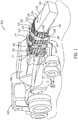
FIG. 1 is rear perspective view of a baler according to example embodiments of the present disclosure; -
FIG. 2 is a top schematic view of the baler ofFIG. 1 ; and -
FIG. 3 is a partial perspective view of a portion of the baler ofFIG. 1 . - Like reference symbols in the various drawings indicate like elements.
- The following describes one or more example embodiments of an agricultural baler with a baling chamber that is defined by a plurality of walls. The different walls are configured for shaping different sides of a bale of agricultural material. At least one wall includes a plurality of segmented panels (i.e., doors, tension panels, etc.) that are arranged along the axis of the baling chamber. The segmented panels are decoupled from each other and configured for independent movement as shown in the accompanying figures of the drawings described briefly above. Various modifications to the example embodiments may be contemplated by one of skill in the art.
- As used herein, unless otherwise limited or modified, lists with elements that are separated by conjunctive terms (e.g., "and") and that are also preceded by the phrase "one or more of" or "at least one of" indicate configurations or arrangements that potentially include individual elements of the list, or any combination thereof. For example, "at least one of A, B, and C" or "one or more of A, B, and C" indicates the possibilities of only A, only B, only C, or any combination of two or more of A, B, and C (e.g., A and B; B and C; A and C; or A, B, and C).
- Furthermore, in detailing the disclosure, terms of direction, such as "forward," "rear," "front," "back," "longitudinal," "transverse," "lateral," "horizontal," and "vertical" may be used. Such terms are defined, at least in part, with respect to the direction in which the work vehicle or implement travels during use. The term "forward" and the abbreviated term "fore" (and any derivatives and variations) refer to a direction corresponding to the direction of travel of the work vehicle, while the term "aft" (and derivatives and variations) refer to an opposing direction. The terms "fore-aft axis" and "longitudinal axis" may also reference an axis extending in fore and aft directions. By comparison, the term "lateral axis" may refer to an axis that is perpendicular to the fore-aft axis and extends in a horizontal plane; that is, a plane containing both the fore-aft and lateral axes. The term "vertical," as appearing herein, may refer to an axis or a direction orthogonal to the horizontal plane containing the fore-aft and lateral axes. The term the "transverse direction" may refer to the lateral direction or the vertical direction (i.e., transverse to the longitudinal axis).
- The following describes one or more example implementations of the disclosed baler as shown in the accompanying figures. The disclosed baler, its method of manufacture and assembly, and its method of operation provide a number of benefits as compared to conventional balers.
- Generally, the baler of the present disclosure may be supported for travel over a crop, ground, field, etc. by wheels mounted to a chassis. The baler may include a pick-up assembly for gathering crop material. The crop material gathered by the pick-up assembly may be routed upward and rearward through the baler and formed into flakes in some embodiments. The baler may also successively compress multiple flakes of crop material together using a bale chamber structure. The bale chamber structure may define a baling chamber wherein the flakes are compressed until the bale has been formed.
- The bale chamber structure may include one or more walls (i.e., structural members, tension panels, etc.) that define the inner surfaces of the baling chamber. The walls may extend along a longitudinal axis of the baling chamber. The walls may contain the crop material and serve to restrict its movement as it travels through the baling chamber.
- In some embodiments, at least one wall may comprise a plurality of segment panels (i.e., doors, etc.). The segment panels may be arranged end-to-end along the longitudinal axis of the baling chamber in some embodiments. The segment panels may be moveably attached to a frame of the baler independent of each other. For example, the segment panels may be pivotally (rotationally) attached to the frame via independent joints. Thus, in some embodiments, the segment panels may be decoupled from each other. Accordingly, the segment panels may move independent of each other when moving relative to the frame.
- By moving the segment panels relative to each other, a cross section of the baling chamber (taken perpendicular to the longitudinal axis) and/or a longitudinal profile of the baling chamber (taken along the longitudinal axis) may be changed. Also, the forces on one segment panel may transfer directly to the frame, without transferring to another segment panel. More specifically, a force restraining one segment panel against longitudinal movement may transfer directly to the frame instead of transferring to another segment panel.
- The baler may further include an actuator system for actuating at least one of the segment panels relative to another. In some embodiments, the actuator system may include an associated control system for controlling movement of the panels. Thus, the geometry of the baling chamber may be adjusted in a controlled manner. Also, pressure, compressive force, frictional force, and/or other loads on the flake or other crop material within the baling chamber may be controlled, adjusted, and finely tuned via control of the actuator system.
- Accordingly, the density of the bale may be controlled. In other words, the baler of the present disclosure may repeatedly provide bales that have a substantially consistent density during operation, regardless of the particular characteristics of the crop material being baled. The baler may provide a wide range of extruding forces on the crop material, and the independently moveable segment panels may distribute the loads along the length of the baling chamber. Furthermore, the baler of the present is configured to distribute loads more evenly because of the segmented and independently moveable segment panels.
- The baling chamber may also be adjusted, for example, according to one or more characteristics of the crop material. For example, the segment panels may be adjusted according to the type of crop, the moisture level of the crop material, or other characteristics.
- Referring now to
FIG. 1 , a work vehicle, such as abaler 100, is depicted according to example embodiments of the present disclosure. In some embodiments, thebaler 100 may include one ormore wheels 101 that are attached to achassis 103. Thebaler 100 is shown being towed by a towingvehicle 102, such as a tractor. The towingvehicle 102 may be hitched to thebaler 100 in some embodiments. It will be appreciated that thebaler 100 may be towed by another vehicle without departing from the scope of the present disclosure. It will also be appreciated that thebaler 100 may be self-propelled without departing from the scope of the present disclosure. - The
baler 100 may encounter a windrow or other arrangement of crop material (not shown) during travel through the field. A pick-upassembly 106 may gather the crop material and move it into a baling implement 107 for forming abale 110 of the crop material. The baling implement 107 may be disposed rearward from the pick-upassembly 106 with respect to a travel direction of thebaler 100. - Generally, the baling implement 107 may include a
frame 121 and abale chamber structure 114. Thebale chamber structure 114 may define abaling chamber 124. Crop material may move rearward along alongitudinal axis 126 of the balingchamber 124, and the inner surfaces of thebale chamber structure 114 may compress and shape respective sides of thebale 110, and thebale 110 may be output from the rear end of thebaler 100. - In some embodiments, the
bale chamber structure 114 may be configured as a square baler, which is configured to form thebale 110 with a cuboid shape and with a rectangular and/or square cross section. However, it will be appreciated that thebale chamber structure 114 may be configured to form bales of other shapes without departing from the scope of the present disclosure. - The
bale chamber structure 114 and the balingchamber 124 are represented schematically inFIG. 2 according to example embodiments. As shown, the balingchamber 124 may be configured to include aninlet portion 136, and avariable portion 138. Theinlet portion 136 may have a substantially fixed cross sectional area and/or longitudinal profile, whereas the cross sectional area and/or longitudinal profile may be selectively varied as will be discussed. Aninlet 125 of thebale chamber structure 114 may be defined proximate the transition between theinlet portion 136 and thevariable portion 138, and thevariable portion 138 may define anoutlet 127 of thebale chamber structure 114. Theinlet 125 may receive crop material from the pick-up assembly 106 (FIG. 1 ). - As shown in
FIG. 2 , thebaler 100 may further include acompaction member 132. Thecompaction member 132 may be areciprocating plunger 134 in some embodiments. Theplunger 134 may be received at least partly within theinlet portion 136 of the balingchamber 124. Theplunger 134 may reciprocate back and forth along theaxis 126. Theplunger 134 may reciprocate with respect to thebale chamber structure 114 to provide crop material into the balingchamber 124. Theplunger 134 may also operate in cooperation with thebale chamber structure 114 to compress the crop material within the balingchamber 124. During operation, theplunger 134 may push the crop material against the internal surfaces of thechamber structure 114 and against previously formed flakes within the balingchamber 124. This action may progressively form thebale 110 as the material moves rearward along theaxis 126. It will be appreciated that thebaler 100 may include another compaction member 132 (other than a plunger 134) without departing from the scope of the present disclosure. For example, in an additional embodiment, thecompaction member 132 may comprise an auger for moving and compacting the crop material within the balingchamber 124. - Referring now to
FIGS. 1 ,2 , and3 , thebale chamber structure 114 will be discussed in detail according to example embodiments. As shown, thebale chamber structure 114 may include a plurality ofwalls 128 that cooperate to define the balingchamber 124. Thewalls 128 may extend along theaxis 126 and may be configured for forming respective sides of thebale 110. As shown inFIG. 1 , the plurality ofwalls 128 may include afloor 116, a first side wall 118 (or also first wall 118), a second side wall 120 (or also second wall 120), and atop wall 122. Thefirst side wall 118 and thesecond side wall 120 are represented schematically inFIG. 2 . Furthermore, inFIG. 3 , thefloor 116, thefirst side wall 118, and portions of theframe 121 are shown in detail. - The
floor 116 may be horizontal and may be fixed to theframe 121 and/or thechassis 103. The first andsecond side walls floor 116 and may be spaced apart laterally to be disposed on opposite sides of theaxis 126 of the balingchamber 124. As shown inFIG. 1 , thetop wall 122 may extend horizontally between the first andsecond side walls floor 116. Accordingly, in some embodiments, thefloor 116, thefirst side wall 118, thesecond side wall 120, and thetop wall 122 may collectively define the rectangular or square cross section (taken perpendicular to the axis 126) of the balingchamber 124. - Referring now to
FIG. 3 , features of theframe 121 that support thefirst side wall 118 will be discussed according to example embodiments. As shown, theframe 121 may include a firstelongate member 146. The firstelongate member 146 may be a beam, bar, shaft, or other elongate structure that extends generally along theaxis 126 of thebale chamber structure 114. The firstelongate member 146 may be substantially rigid and strong and may be constructed from steel or other suitable material. Theframe 121 may further include a secondelongate member 148. The secondelongate member 148 may also be a beam, bar, shaft, or other elongate structure that extends along theaxis 126. In some embodiments, the secondelongate member 148 may be fixed to thechassis 103 of thebaler 100. The secondelongate member 148 may be spaced apart from the firstelongate member 146 at a distance in the vertical direction (i.e., in a direction that is transverse to that of the axis 126). - The
frame 121 may additionally include one or more support members, such as afirst support member 139, asecond support member 141, and athird support member 145. The first, second, andthird support members support members elongate members third support members axis 126 with thesecond support member 141 disposed between the first andthird support members - The portion of the
frame 121 represented inFIG. 3 , may support thefirst side wall 118 of thebale chamber structure 114. To this end, the firstelongate member 146, thefirst support member 139, the secondelongate member 148, and thesecond support member 141 may cooperatively define a substantially rectangular frame structure for supporting a portion of thefirst side wall 118. Likewise, the firstelongate member 146, thesecond support member 141, the secondelongate member 148, and thethird support member 145 may cooperatively define a substantially rectangular frame structure for supporting another portion of thefirst side wall 118. - Also, as shown in
FIGS. 1 and3 , theframe 121 may include a plurality of yokes, including anupstream yoke 147 and adownstream yoke 149. Theupstream yoke 147 may be disposed proximate theinlet 125, and thedownstream yoke 149 may be disposed proximate theoutlet 127. Theyokes walls 128 of the balingchamber 124. Theyokes elongate members yokes chassis 103 of thebaler 100. - Referring now to
FIGS. 1 ,2 , and3 , the plurality ofwalls 128 will be discussed in detail according to example embodiments. Thewalls 128 may be supported by theframe 121. In some embodiments, one or more of thewalls 128 may be fixed to theframe 121. For example, thefloor 116 may be fixed to theframe 121 in some embodiments. - Also, in some embodiments, at least one segment of at least one of the
walls 128 may be moveably supported by theframe 121. For example, in some embodiments, thefirst side wall 118, thesecond side wall 120, and thetop wall 122 may include at least one portion that is moveably supported by theframe 121. - Moreover, in some embodiments, one or more of the
walls 128 may be segmented along theaxis 126, and each segment may be moveably supported by theframe 121. These moveably-attached segments may cooperatively define therespective wall 128 and may be configured for shaping one side of thebale 110 as the crop material moves along theaxis 126. In the illustrated embodiment, the first andsecond side walls top wall 122 and/or thefloor 116 may be similarly segmented without departing from the scope of the present disclosure. - The configuration of the
first side wall 118 will now be discussed in detail according to example embodiments. It will be appreciated that thesecond side wall 120 may be similarly configured. - As shown in
FIGS. 2 and3 , thefirst side wall 118 may include anupstream panel 183, afirst segment panel 151, and asecond segment panel 153. The upstream panel and the first andsecond segment panels upstream panel 183 may be fixed to theframe 121 such that thepanel 183 remains substantially parallel to theaxis 126. Thefirst segment panel 151 may be moveably attached to theframe 121, proximate theinlet 125 and theplunger 134, and thesecond segment panel 153 may be moveably attached to theframe 121, proximate theoutlet 127. Accordingly, theupstream panel 183, thefirst segment panel 151, and thesecond segment panel 153 may be arranged sequentially along theaxis 126 to cooperatively define thefirst side wall 118. As shown inFIG. 2 , theupstream panel 183 may define theinlet portion 136, and the first andsecond segment panels variable portion 138 of thefirst side wall 118. Although thefirst side wall 118 includes two moveable segment panels (i.e., the first andsecond segment panels 151, 153) in the illustrated embodiment, it will be appreciated that there may be three or more segment panels in additional embodiments. - The
first segment panel 151 may include aninner surface 159 that faces inward toward theaxis 126 and anouter surface 161 that faces outward. Theinner surface 159 may be substantially smooth and flat in some embodiments. Theouter surface 161 may include a plurality of stiffening structures 171 (FIGS. 1 and3 ) that extend along theaxis 126 and that provide stiffening. Thefirst segment panel 151 may also include an upstream end 163 (or also first upstream end 163) and a downstream end 165 (or also first downstream end 165) that extend vertically. Additionally, thefirst segment panel 151 may include anupper edge 167 and alower edge 169 that extend horizontally. - Likewise, the
second segment panel 153 may include aninner surface 173 that faces inward toward theaxis 126 and anouter surface 175 that faces outward. Theinner surface 173 may be substantially smooth and flat in some embodiments. Theouter surface 175 may include the stiffeningstructures 171. Thesecond segment panel 153 may also include an upstream end 177 (or also second upstream end 177) and a downstream end 179 (or also second downstream end 179) that extend vertically. Additionally, thesecond segment panel 153 may include anupper edge 185 and alower edge 181 that extend horizontally. - The
first segment panel 151 may be moveably attached to theframe 121. For example, thefirst segment panel 151 may be pivotally attached to theframe 121 at afirst pivot joint 187. The first pivot joint 187 may extend vertically between the firstelongate member 146 and the secondelongate member 148 and may be attached to both. The pivot joint 187 may also be attached to thefirst segment panel 151, proximate theupstream end 163. As shown inFIG. 2 , the first pivot joint 187 may also be substantially coincidental with the end of theupstream panel 183. The first pivot joint 187 may be a hinge configured for supporting rotation of thefirst segment panel 151 relative to theframe 121 about a vertical axis of rotation 203 (or also first axis of rotation 203). - Accordingly, as represented in
FIG. 2 , thefirst segment panel 151 may be supported for rotational movement between a first position (shown in phantom) and a second position (shown in solid lines) relative to theframe 121. In the first position, thefirst segment panel 151 may be substantially parallel to theaxis 126 and aligned with the first and secondelongate members first segment panel 151 may be received within the vertical opening defined between the first and secondelongate members FIGS. 2 and3 ), thefirst segment panel 151 may be disposed at an acute angle relative to theaxis 126, and thedownstream end 165 may be rotated inwardly toward theaxis 126 to be spaced apart from the first and secondelongate members 146, 148 (FIG. 3 ). - Likewise, the
second segment panel 153 may be moveably attached to theframe 121. For example, thesecond segment panel 153 may be pivotally attached to theframe 121 at asecond pivot joint 189. The second pivot joint 189 may also be attached to thesecond segment panel 153, proximate theupstream end 177. Accordingly, the second pivot joint 189 may be a hinge configured for supporting rotation of thesecond segment panel 153 relative to theframe 121 about a vertical axis of rotation 205 (or also second axis of rotation 205). The second pivot joint 189 and its axis of rotation 205 may be spaced apart at a distance from the first pivot joint 187 and its axis ofrotation 203 in a direction that is parallel to theaxis 126. Accordingly, like thefirst segment panel 151, thesecond segment panel 153 may be supported for rotational movement between a first position (shown in solid lines) and a second position (shown in phantom lines) relative to theframe 121. - Accordingly, the
first segment panel 151 may be moveably attached to the frame 121 (via the first pivot joint 187) independent of thesecond segment panel 153. Likewise, thesecond segment panel 153 may be moveably attached to the frame 121 (via the second pivot joint 189) independent of thefirst segment panel 151. Thus, thefirst segment panel 151 may be supported for movement independent of thesecond segment panel 153 and vice versa. Specifically, thedownstream end 165 of thefirst segment panel 151 may be pivoted inward and outward without affecting the position of thesecond segment panel 153. Likewise, thedownstream end 179 of thesecond segment panel 153 may be pivoted inward and outward without affecting the position of thefirst segment panel 151. This is because thefirst segment panel 151 may be decoupled from thesecond segment panel 153. The first andsecond segment panels gap 195 between thedownstream end 165 of thefirst segment panel 151 and theupstream end 177 of thesecond segment panel 153. - When the
first segment panel 151 is in the first position, thedownstream end 165 may be substantially aligned and/or coincidental with theupstream end 177 of thesecond segment panel 153. Accordingly, thegap 195 may have a reduced size and thewall 118 may be substantially continuous and uninterrupted in this region. In contrast, when thefirst segment panel 151 is in the second position, thedownstream end 165 may be disposed inwardly such that the size of thegap 195 is increased and thewall 118 is discontinuous in this region. Likewise, thesecond segment panel 153 may be moved between its first and second positions, for example, for varying a cross sectional area of theoutlet 127. - As shown in
FIG. 2 , thesecond side wall 120 of the balingchamber 124 may be similar to thefirst side wall 118. Specifically, thesecond side wall 120 may include anupstream panel 143, athird segment panel 155 and afourth segment panel 157. Thethird segment panel 155 may be moveably attached to theframe 121, proximate theinlet 125, and thefourth segment panel 157 may be moveably attached to theframe 121, proximate theoutlet 127. Accordingly, theupstream panel 143, thethird segment panel 155, and thefourth segment panel 157 may be arranged sequentially along theaxis 126 to cooperatively define thesecond side wall 120. - Moreover, as shown in
FIG. 2 , thebaler 100 may also include anactuator system 168. Generally, theactuator system 168 may include a plurality of actuators, such as afirst actuator 191 and asecond actuator 193, for actuating thesegment panels first side wall 118. Theactuator system 168 may include similar actuators for thesegment panels second side wall 120 as well. - The
baler 100 may further include an associatedcontrol system 197 for controlling the first andsecond actuators control system 197 may communicate with other systems or devices (including other controllers) in various known ways, including via a CAN bus of thebaler 100 or the towingvehicle 102 wirelessly, hydraulically, or otherwise. - The first and
second actuators second actuators - The
first actuator 191 may be configured to rotate thefirst segment panel 151 relative to theframe 121 about the axis ofrotation 203. To this end, thefirst actuator 191 may be attached to thefirst segment panel 151 and may be attached to theupstream yoke 147. In the embodiment ofFIG. 2 , thefirst actuator 191 is illustrated as having a hydraulic cylinder that actuates laterally relative to theaxis 126; however, it will be appreciated that thefirst actuator 191 may be configured differently without departing from the scope of the present disclosure. Thefirst actuator 191 may also include a lever or other mechanism that provides a mechanical advantage for movement of thefirst segment panel 151 between its different positions. Likewise, thesecond actuator 193 may be configured to rotate thesecond segment panel 153 about the axis of rotation 205. - The
control system 197 may include aprocessor 199 and a plurality ofsensors 201. Thesensors 201 may be of any suitable type, such as pressure sensors, proximity switches, voltmeters, and the like. - In some embodiments, at least one
sensor 201 may be operably coupled to theplunger 134 to detect how much pressure that theplunger 134 is applying to the crop material and/or how much back pressure the crop material is applying to theplunger 134. Also, at least onesensor 201 may be operably coupled to theactuator 191 to: (a) detect the load on theactuator 191; (b) detect the position and/or orientation of thefirst segment panel 151; and/or (c) detect another characteristic associated with movement of thefirst segment panel 151. Also, at least onesensor 201 may be operably coupled to theactuator 193 for detecting similar conditions associated with theactuator 193 and/or thesegment panel 153. - The
control system 197 may generate and send control signals to reciprocate theplunger 134. Thecontrol system 197 may also generate and send control signals to theactuator 191 and/or theactuator 193 for moving and adjusting the first and/orsecond segment panels control system 197 may generate and send control signals to actuators for moving the third andfourth segment panels second side wall 120. - Various methods may be used for operation of the
control system 197. Theprocessor 199 may determine a target characteristic of the baling chamber 124 (i.e., a baling chamber characteristic) before the baling process begins. In some embodiments, theprocessor 199 may determine a target longitudinal profile for the balingchamber 124. The target profile may include, for example, target positions for the first, second, third andfourth segment panels control system 197 may generate and send control signals to the actuators such that the actual profile of the balingchamber 124 achieves the target profile determined by theprocessor 199. Additionally, in some embodiments, theprocessor 199 may determine a target pressure for theactuator system 168 to apply to thesegment panels control system 197 may generate and send control signals to the actuators for achieving the target loads. - Also, in some embodiments, the sensor(s) 201 may provide respective feedback signals back to the
processor 199. Theprocessor 199 may receive the feedback and process the feedback for various purposes. For example, the feedback may allow theprocessor 199 to determine how to adjust the position and/or pressure on thesegment panels control system 197 may make these adjustments to provide thebale 110 with a predetermined shape and geometry and with a predetermined density. - Accordingly, the
baler 100 of the present disclosure provides a highly adjustable andcontrollable baling chamber 124. The balingchamber 124 may be varied to, for example, change the cross-sectional area (and, thus, the longitudinal profile) of the balingchamber 124. The balingchamber 124 may also be adjusted to vary and control the amount of friction between the crop material and the internal surface of thebale chamber structure 114. Accordingly, thebaler 100 of the present disclosure may repeatedly providebales 110 that have a substantially consistent shape and density during operation, regardless of the quality of the crop material being baled. - Furthermore, because the
walls downstream end 165 of thefirst segment panel 151 may block crop material that tends to rebound in the upstream direction, especially when moved inward toward theaxis 126. Thethird segment panel 155 may similarly prevent rebound of the crop material. - Also, the segments of the
walls segment panels bale 110. Moreover, the plurality ofpivot joints frame 121 as compared to conventional bale chamber structures. - Moreover, in some cases, adjustments to the
segment panels segment panels - In addition, the
bale chamber structure 128 may be relatively short as compared to those of the prior art. This may improve transport mobility of thebaler 100. - Lastly, the
baler 100 may facilitate ejection of the crop material. For example, at the end of a run, the user may wish to remove the last of the crop material from the balingchamber 124. Because thesecond segment panel 153 is relatively short, theactuator 193 may only need to move through a small stroke to move thesecond segment panel 153 sufficiently for removal of the crop material. The same may be true for thefourth segment panel 157 and its actuator. - Thus, the
baler 100 provides a high degree of precision when adjusting the balingchamber 124. Also, several features provide added convenience for the user. - The terminology used herein is for the purpose of describing particular embodiments only and is not intended to be limiting of the disclosure. As used herein, the singular forms "a", "an" and "the" are intended to include the plural forms as well, unless the context clearly indicates otherwise. It will be further understood that the terms "comprises" and/or "comprising," when used in this specification, specify the presence of stated features, integers, steps, operations, elements, and/or components, but do not preclude the presence or addition of one or more other features, integers, steps, operations, elements, components, and/or groups thereof.
- The description of the present disclosure has been presented for purposes of illustration and description, but is not intended to be exhaustive or limited to the disclosure in the form disclosed. Many modifications and variations will be apparent to those of ordinary skill in the art without departing from the scope and spirit of the disclosure. Explicitly referenced embodiments herein were chosen and described in order to best explain the principles of the disclosure and their practical application, and to enable others of ordinary skill in the art to understand the disclosure and recognize many alternatives, modifications, and variations on the described example(s). Accordingly, various embodiments and implementations other than those explicitly described are within the scope of the following claims.
Claims (15)
- A baler configured to form a bale (110) of crop material, the baler (100) comprising:a frame (121);a bale chamber structure (114) that is supported by the frame (121), the bale chamber structure (114) including a plurality of walls (128) that cooperate to define a baling chamber (124) that extends along a longitudinal axis (126), the plurality of walls (128) configured to shape different sides of the bale (110), at least one of the plurality of walls (128) including:a first segment panel (151) that is moveably attached to the frame (121); anda second segment panel (153) that is arranged in a downstream direction from the first segment panel (151) with respect to the longitudinal axis (126), the second segment panel (153) being moveably attached to the frame (121) independent of the first segment panel (151).
- The baler of claim 1, wherein the first segment panel (151) is moveably attached to the frame (121) via a first joint;wherein the second segment panel (153) is moveably attached to the frame (121) via a second joint; andwherein the first joint and the second joint are spaced apart along the longitudinal axis (126).
- The baler of claim 1 or 2, wherein at least one of the first joint and the second joint is a pivot joint (187, 189).
- The baler according to at least one of the preceding claims, wherein the first segment panel (151) is moveably attached to the frame (121) via the pivot joint (187);wherein the pivot joint (187) is configured to rotate the first segment panel (151) about an axis of rotation (203);wherein the first segment panel (151) includes an upstream end (163) and a downstream end (165); andwherein the axis of rotation (203) is proximate the upstream end (163).
- The baler according to at least one of the preceding claims, wherein the axis of rotation (203) extends substantially along a vertical direction.
- The baler according to at least one of the preceding claims, wherein the frame (121) includes a first elongate member (146) and a second elongate member (148) that extend along the longitudinal axis (126);wherein the first elongate member (146) and the second elongate member (148) are spaced apart in direction that is transverse to the longitudinal axis (126); andwherein at least one of the first joint and the second joint is attached to the first elongate member (146) and the second elongate member (148).
- The baler according to at least one of the preceding claims, further comprising an actuator system (168) with a first actuator (191) and a second actuator (193);wherein the first actuator (191) is configured to actuate the first segment panel (151) relative to the frame (121) independent of the second segment panel (153); andwherein the second actuator (193) is configured to actuate the second segment panel (153) relative to the frame (121) independent of the first segment panel (151).
- The baler according to at least one of the preceding claims, wherein the first actuator (191) is configured to rotate the first segment panel (151) relative to the frame (121) about a first axis of rotation ; and
wherein the second actuator (193) is configured to rotate the second segment panel (153) relative to the frame (121) about a second axis of rotation. - The baler according to at least one of the preceding claims, further comprising a control system configured to communicate with the first actuator (191) for controlled actuation of the first segment panel (151); and
wherein the control system is configured to communicate with the second actuator (193) for controlled actuation of the second segment panel (153). - The baler according to at least one of the preceding claims, wherein the bale chamber structure (114) defines an inlet (125) of the baling chamber (124) and an outlet (127) of the baling chamber (124);further comprising a compaction member (132) disposed proximate the inlet (125) and configured to move the crop material away from the inlet (125) toward the outlet (127) and form the bale (110); andwherein the first segment panel (151) is disposed proximate the compaction member (132); andwherein the second segment panel (153) partly defines the outlet (127).
- The baler according to at least one of the preceding claims, wherein the frame (121) includes a first elongate member (146) and a second elongate member (148) that extend along the longitudinal axis (126);wherein the first elongate member (146) and the second elongate member (148) are spaced apart to define an opening therebetween; andwherein the first segment panel (151) and the second segment panel (153) are received within the opening and are configured to move within the opening relative to the frame (121).
- The baler according to at least one of the preceding claims, wherein the plurality of walls (128) includes a first wall (118) and a second wall (120) that are configured to shape different sides of the pale;wherein the first wall (118) faces opposite the second wall (120) across the baling chamber (124);wherein the first wall (118) includes the first segment panel (151) and the second segment panel (153); andwherein the second wall (120) includes:a third segment panel (155) that is moveably attached to the frame (121); anda fourth segment panel (157) that is arranged in a downstream direction from the first segment panel (151) with respect to the longitudinal axis (126), the fourth segment panel (157) being moveably attached to the frame (121), the fourth segment panel (157) being decoupled from the third segment panel (155) and configured for movement independent of the third segment panel (155).
- The baler according to at least one of the preceding claims, wherein the first segment panel (151) includes a first upstream end (163) and a first downstream end (165);
wherein the second segment panel (153) includes a second upstream end (177) and a second downstream end (179);
wherein the second upstream end (177) is disposed proximate the first downstream end (165);
wherein the first segment panel (151) is configured for movement independent of the second segment panel (153) to vary a gap defined between the second upstream end (177) and the first downstream end (165). - A method of operating a baler (100) having a bale chamber structure (114) that defines a variable baling chamber (124) that extends along a longitudinal axis (126), the baling chamber (124) partly defined by a wall configured to define a side of a bale (110) of crop material, the method comprising:actuating a first segment panel (151) of the wall relative to a frame (121) about a first joint that moveably attaches the first segment panel (151) to the frame (121); andactuating a second segment panel (153) of the wall relative to the frame (121) about a second joint that moveably attaches the second segment panel (153) to the frame (121) independent of the first segment panel (151).
- A baler configured to form a rectangular bale (110) of crop material, the baler (100) comprising:a frame (121) with a first elongate member (146) and a second elongate member (148) that are spaced apart in a vertical direction to define an opening between the first elongate member (146) and the second elongate member (148);a bale chamber structure (114) that is supported by the frame (121), the bale chamber structure (114) including a plurality of walls (128) that cooperate to define a baling chamber (124) that extends along a longitudinal axis (126), the plurality of walls (128) configured to shape different sides of the bale, at least one of the plurality of walls (128) including a first segment panel (151) that is received in the opening and moveably attached to the first elongate member (146) and the second elongate member (148) via a first pivot joint (187), the at least one of the plurality of walls (128) including a second segment panel (153) that is arranged in a downstream direction from the first segment panel (151) with respect to the longitudinal axis (126), the second segment panel (153) being received in the opening and moveably attached to the first elongate member (146) and the second elongate member (148) via a second pivot joint (189) that is independent of the first segment panel (151), the second segment panel (153) configured for movement that varies a size of a gap between the first segment panel (151) and the second segment panel (153);an actuator system (168) configured to independently actuate the first segment panel (151) and the second segment panel (153) relative to the frame (121); anda control system configured to control the actuator system (168) to control independent movement of the first segment panel (151) and the second segment panel (153) relative to the frame (121).
Applications Claiming Priority (1)
| Application Number | Priority Date | Filing Date | Title |
|---|---|---|---|
| US15/895,395 US10945377B2 (en) | 2018-02-13 | 2018-02-13 | Baler with segmented tension panels |
Publications (2)
| Publication Number | Publication Date |
|---|---|
| EP3524047A1 true EP3524047A1 (en) | 2019-08-14 |
| EP3524047B1 EP3524047B1 (en) | 2024-12-25 |
Family
ID=65411805
Family Applications (1)
| Application Number | Title | Priority Date | Filing Date |
|---|---|---|---|
| EP19156640.5A Active EP3524047B1 (en) | 2018-02-13 | 2019-02-12 | Baler with segmented tension panels |
Country Status (2)
| Country | Link |
|---|---|
| US (1) | US10945377B2 (en) |
| EP (1) | EP3524047B1 (en) |
Cited By (1)
| Publication number | Priority date | Publication date | Assignee | Title |
|---|---|---|---|---|
| DE102020104515A1 (en) | 2020-02-20 | 2021-08-26 | Ingo Dreher | Pressing device, press system and method for providing a bale pressed from plant material |
Families Citing this family (9)
| Publication number | Priority date | Publication date | Assignee | Title |
|---|---|---|---|---|
| EP3818814B1 (en) * | 2019-11-08 | 2023-08-30 | CNH Industrial Belgium NV | Agricultural system |
| CN112219568B (en) * | 2020-09-24 | 2022-04-12 | 东台市高科技术创业园有限公司 | A straw pelletizing unit |
| US11903345B2 (en) * | 2021-04-06 | 2024-02-20 | Deere & Company | Bale ejection system for a baler implement |
| CN113692860B (en) * | 2021-08-24 | 2024-01-23 | 中国一拖集团有限公司 | Compression force and bale rule rate control mechanism and control method of square baler |
| FR3138600B1 (en) * | 2022-08-05 | 2024-08-23 | EMI Straw | Machine for manufacturing parallelepiped agricultural products, and corresponding agricultural product |
| CN115226505B (en) * | 2022-09-19 | 2022-12-23 | 新乡市花溪科技股份有限公司 | Bundling machine packing compaction processing apparatus |
| US12137637B2 (en) * | 2023-04-04 | 2024-11-12 | Deere & Company | Panel compression system for baler implement |
| US12507633B2 (en) | 2023-04-11 | 2025-12-30 | Deere & Company | Panel compression system for baler implement |
| CN118202869B (en) * | 2024-04-17 | 2026-04-28 | 山东五征高北农牧机械有限公司 | A structure and method for suppressing material rebound on the wall surface of an opposed compression square baler. |
Citations (6)
| Publication number | Priority date | Publication date | Assignee | Title |
|---|---|---|---|---|
| FR1340188A (en) * | 1962-05-21 | 1963-10-18 | Thiebaud Bourguignonne Sa | Device for regulating the density of bales compressed in fodder or straw balers |
| DD287188A5 (en) * | 1989-08-22 | 1991-02-21 | Kombinat Fortschritt Landmaschinen Veb Erntemaschinen Neustadt,De | CONTROL DEVICE FOR THE PRESS DENSITY OF BALER |
| EP1095558A1 (en) * | 1996-04-25 | 2001-05-02 | Maasland N.V. | A bale press |
| US20100224085A1 (en) * | 2009-03-05 | 2010-09-09 | Hoover Larry L | Hydraulically or manually controlled side tension rails to control bale length variation in a 14" x 18" square bale chamber |
| EP2614704A1 (en) * | 2012-01-16 | 2013-07-17 | CNH Belgium N.V. | Improved bale chamber configurations |
| EP3117699A1 (en) * | 2015-07-14 | 2017-01-18 | CNH Industrial Belgium nv | Rectangular baler with a density control system and density control method |
Family Cites Families (20)
| Publication number | Priority date | Publication date | Assignee | Title |
|---|---|---|---|---|
| US2470278A (en) * | 1946-12-06 | 1949-05-17 | Deere Mfg Co | Baling press |
| US3424081A (en) * | 1966-01-10 | 1969-01-28 | Earl M Hoke | Bale compacting attachment for balers |
| US3479950A (en) * | 1967-12-18 | 1969-11-25 | Percy F Freeman | Baler for cotton motes and other materials |
| US4489648A (en) * | 1984-01-18 | 1984-12-25 | Sperry Corporation | Baler density control mechanism |
| US4594942A (en) * | 1985-02-12 | 1986-06-17 | B.V. Machinefabriek Boa | Baling press with large supply hopper |
| US5819643A (en) | 1997-12-18 | 1998-10-13 | New Holland North America, Inc. | Baler density control system |
| DE10145691A1 (en) | 2001-08-10 | 2003-03-13 | Deere & Co | baler |
| DE10145690A1 (en) * | 2001-08-10 | 2003-03-13 | Deere & Co | baler |
| NL2000013C2 (en) | 2006-02-21 | 2007-08-22 | Vredo Beheer B V | Vehicle-mounted equipment for compression of agricultural produce to form bales comprises at least one compression chamber, compression equipment for exertion of pressure on agricultural product in compression chamber |
| GB2439935B (en) * | 2006-07-08 | 2011-09-14 | Lyndex Recycling Systems Ltd | Compacting and Bailing Apparatus |
| US7992491B1 (en) * | 2008-04-25 | 2011-08-09 | Forest Concepts, LLC | Engineered top infeed hopper system |
| US8925451B2 (en) * | 2008-04-25 | 2015-01-06 | Forest Concepts, LLC | Engineered top infeed hopper system with side-mounted cutting device |
| US20120204737A1 (en) | 2010-12-27 | 2012-08-16 | Agco Corporation | Tracking Bale Density Door for Big Square Baler |
| BE1020370A3 (en) | 2012-01-16 | 2013-08-06 | Cnh Belgium Nv | CROP PARAMETER DEPENDENT ADJUSTMENT OF A BALEN ROOM CONFIGURATION. |
| BE1020599A3 (en) | 2012-03-30 | 2014-01-07 | Cnh Belgium Nv | MOVEABLE FRICTION BLOCKS FOR A RECTANGULAR BALL PRESS. |
| BE1020598A3 (en) | 2012-03-30 | 2014-01-07 | Cnh Belgium Nv | FRICTION BLOCKS FOR A RECTANGULAR BALL PRESS. |
| US10058037B2 (en) | 2014-10-28 | 2018-08-28 | Deere & Company | Baler and method for improved bale handling |
| WO2016100223A1 (en) | 2014-12-18 | 2016-06-23 | Agco Corporation | Square baler providing side-to-side bale uniformity |
| WO2017005635A1 (en) | 2015-07-03 | 2017-01-12 | Cnh Industrial Belgium Nv | Retractable blocks in the doors of a large square baler |
| EP3322283B1 (en) | 2015-07-14 | 2019-12-04 | CNH Industrial Belgium N.V. | Rectangular baler having a wall positioning system and wall positioning method |
-
2018
- 2018-02-13 US US15/895,395 patent/US10945377B2/en active Active
-
2019
- 2019-02-12 EP EP19156640.5A patent/EP3524047B1/en active Active
Patent Citations (6)
| Publication number | Priority date | Publication date | Assignee | Title |
|---|---|---|---|---|
| FR1340188A (en) * | 1962-05-21 | 1963-10-18 | Thiebaud Bourguignonne Sa | Device for regulating the density of bales compressed in fodder or straw balers |
| DD287188A5 (en) * | 1989-08-22 | 1991-02-21 | Kombinat Fortschritt Landmaschinen Veb Erntemaschinen Neustadt,De | CONTROL DEVICE FOR THE PRESS DENSITY OF BALER |
| EP1095558A1 (en) * | 1996-04-25 | 2001-05-02 | Maasland N.V. | A bale press |
| US20100224085A1 (en) * | 2009-03-05 | 2010-09-09 | Hoover Larry L | Hydraulically or manually controlled side tension rails to control bale length variation in a 14" x 18" square bale chamber |
| EP2614704A1 (en) * | 2012-01-16 | 2013-07-17 | CNH Belgium N.V. | Improved bale chamber configurations |
| EP3117699A1 (en) * | 2015-07-14 | 2017-01-18 | CNH Industrial Belgium nv | Rectangular baler with a density control system and density control method |
Cited By (2)
| Publication number | Priority date | Publication date | Assignee | Title |
|---|---|---|---|---|
| DE102020104515A1 (en) | 2020-02-20 | 2021-08-26 | Ingo Dreher | Pressing device, press system and method for providing a bale pressed from plant material |
| US12240198B2 (en) | 2020-02-20 | 2025-03-04 | Ingo Dreher | Pressing device, pressing system and method for providing a bale pressed from plant material |
Also Published As
| Publication number | Publication date |
|---|---|
| US10945377B2 (en) | 2021-03-16 |
| US20190246566A1 (en) | 2019-08-15 |
| EP3524047B1 (en) | 2024-12-25 |
Similar Documents
| Publication | Publication Date | Title |
|---|---|---|
| EP3524047B1 (en) | Baler with segmented tension panels | |
| US8539878B2 (en) | Square baler and a related control method | |
| CA2347565C (en) | Adjustable harvest material transport assembly for moving the material from a pick-up to a processor inlet | |
| US9913432B2 (en) | Square baler providing side-to-side bale uniformity | |
| EP2403328B1 (en) | Mechanism for applying tension to a bale in the bale case of an agricultural baler | |
| EP3741201B1 (en) | Crop package accumulator | |
| US9038357B2 (en) | Windguard mechanism of a pick-up for an agricultural machine | |
| US10932415B2 (en) | Agricultural crop baler with oscillating side walls | |
| EP2816889A1 (en) | Multi-mode control system for rectangular baler and related method | |
| US6698343B2 (en) | Baling chamber having adjustable cross section | |
| US10588269B2 (en) | Baler with rotatable compression surface | |
| BE1020764A3 (en) | BALL PRESS FOR USE IN AGRICULTURE WITH IMPROVED POSITIONING OF THE FRICTION OR HUMIDITY SENSOR. | |
| EP2701485B1 (en) | Agricultural square baler with controlled bale chute | |
| US6715410B2 (en) | Baling chamber having adjustable cross section | |
| EP3473080B1 (en) | Baler plunger guide system | |
| EP4066624A1 (en) | Agricultural vehicle with independently movable windguard rollers | |
| US20030029148A1 (en) | Baling chamber having adjustable cross section | |
| EP0745320B1 (en) | A bale press | |
| EP4588337A1 (en) | Dual pivot drop floor | |
| EP4445719B1 (en) | Panel compression system for baler implement |
Legal Events
| Date | Code | Title | Description |
|---|---|---|---|
| PUAI | Public reference made under article 153(3) epc to a published international application that has entered the european phase |
Free format text: ORIGINAL CODE: 0009012 |
|
| STAA | Information on the status of an ep patent application or granted ep patent |
Free format text: STATUS: THE APPLICATION HAS BEEN PUBLISHED |
|
| AK | Designated contracting states |
Kind code of ref document: A1 Designated state(s): AL AT BE BG CH CY CZ DE DK EE ES FI FR GB GR HR HU IE IS IT LI LT LU LV MC MK MT NL NO PL PT RO RS SE SI SK SM TR |
|
| AX | Request for extension of the european patent |
Extension state: BA ME |
|
| STAA | Information on the status of an ep patent application or granted ep patent |
Free format text: STATUS: REQUEST FOR EXAMINATION WAS MADE |
|
| 17P | Request for examination filed |
Effective date: 20200214 |
|
| RBV | Designated contracting states (corrected) |
Designated state(s): AL AT BE BG CH CY CZ DE DK EE ES FI FR GB GR HR HU IE IS IT LI LT LU LV MC MK MT NL NO PL PT RO RS SE SI SK SM TR |
|
| STAA | Information on the status of an ep patent application or granted ep patent |
Free format text: STATUS: EXAMINATION IS IN PROGRESS |
|
| 17Q | First examination report despatched |
Effective date: 20200818 |
|
| GRAP | Despatch of communication of intention to grant a patent |
Free format text: ORIGINAL CODE: EPIDOSNIGR1 |
|
| STAA | Information on the status of an ep patent application or granted ep patent |
Free format text: STATUS: GRANT OF PATENT IS INTENDED |
|
| INTG | Intention to grant announced |
Effective date: 20240805 |
|
| GRAS | Grant fee paid |
Free format text: ORIGINAL CODE: EPIDOSNIGR3 |
|
| GRAA | (expected) grant |
Free format text: ORIGINAL CODE: 0009210 |
|
| STAA | Information on the status of an ep patent application or granted ep patent |
Free format text: STATUS: THE PATENT HAS BEEN GRANTED |
|
| AK | Designated contracting states |
Kind code of ref document: B1 Designated state(s): AL AT BE BG CH CY CZ DE DK EE ES FI FR GB GR HR HU IE IS IT LI LT LU LV MC MK MT NL NO PL PT RO RS SE SI SK SM TR |
|
| REG | Reference to a national code |
Ref country code: GB Ref legal event code: FG4D |
|
| REG | Reference to a national code |
Ref country code: CH Ref legal event code: EP |
|
| REG | Reference to a national code |
Ref country code: DE Ref legal event code: R096 Ref document number: 602019063861 Country of ref document: DE |
|
| REG | Reference to a national code |
Ref country code: IE Ref legal event code: FG4D |
|
| REG | Reference to a national code |
Ref country code: LT Ref legal event code: MG9D |
|
| PG25 | Lapsed in a contracting state [announced via postgrant information from national office to epo] |
Ref country code: HR Free format text: LAPSE BECAUSE OF FAILURE TO SUBMIT A TRANSLATION OF THE DESCRIPTION OR TO PAY THE FEE WITHIN THE PRESCRIBED TIME-LIMIT Effective date: 20241225 |
|
| PG25 | Lapsed in a contracting state [announced via postgrant information from national office to epo] |
Ref country code: FI Free format text: LAPSE BECAUSE OF FAILURE TO SUBMIT A TRANSLATION OF THE DESCRIPTION OR TO PAY THE FEE WITHIN THE PRESCRIBED TIME-LIMIT Effective date: 20241225 |
|
| PG25 | Lapsed in a contracting state [announced via postgrant information from national office to epo] |
Ref country code: BG Free format text: LAPSE BECAUSE OF FAILURE TO SUBMIT A TRANSLATION OF THE DESCRIPTION OR TO PAY THE FEE WITHIN THE PRESCRIBED TIME-LIMIT Effective date: 20241225 |
|
| PG25 | Lapsed in a contracting state [announced via postgrant information from national office to epo] |
Ref country code: NO Free format text: LAPSE BECAUSE OF FAILURE TO SUBMIT A TRANSLATION OF THE DESCRIPTION OR TO PAY THE FEE WITHIN THE PRESCRIBED TIME-LIMIT Effective date: 20250325 |
|
| PG25 | Lapsed in a contracting state [announced via postgrant information from national office to epo] |
Ref country code: LV Free format text: LAPSE BECAUSE OF FAILURE TO SUBMIT A TRANSLATION OF THE DESCRIPTION OR TO PAY THE FEE WITHIN THE PRESCRIBED TIME-LIMIT Effective date: 20241225 Ref country code: GR Free format text: LAPSE BECAUSE OF FAILURE TO SUBMIT A TRANSLATION OF THE DESCRIPTION OR TO PAY THE FEE WITHIN THE PRESCRIBED TIME-LIMIT Effective date: 20250326 |
|
| PG25 | Lapsed in a contracting state [announced via postgrant information from national office to epo] |
Ref country code: RS Free format text: LAPSE BECAUSE OF FAILURE TO SUBMIT A TRANSLATION OF THE DESCRIPTION OR TO PAY THE FEE WITHIN THE PRESCRIBED TIME-LIMIT Effective date: 20250325 |
|
| REG | Reference to a national code |
Ref country code: NL Ref legal event code: MP Effective date: 20241225 |
|
| PG25 | Lapsed in a contracting state [announced via postgrant information from national office to epo] |
Ref country code: NL Free format text: LAPSE BECAUSE OF FAILURE TO SUBMIT A TRANSLATION OF THE DESCRIPTION OR TO PAY THE FEE WITHIN THE PRESCRIBED TIME-LIMIT Effective date: 20241225 |
|
| REG | Reference to a national code |
Ref country code: AT Ref legal event code: MK05 Ref document number: 1753357 Country of ref document: AT Kind code of ref document: T Effective date: 20241225 |
|
| PG25 | Lapsed in a contracting state [announced via postgrant information from national office to epo] |
Ref country code: SM Free format text: LAPSE BECAUSE OF FAILURE TO SUBMIT A TRANSLATION OF THE DESCRIPTION OR TO PAY THE FEE WITHIN THE PRESCRIBED TIME-LIMIT Effective date: 20241225 |
|
| PG25 | Lapsed in a contracting state [announced via postgrant information from national office to epo] |
Ref country code: PL Free format text: LAPSE BECAUSE OF FAILURE TO SUBMIT A TRANSLATION OF THE DESCRIPTION OR TO PAY THE FEE WITHIN THE PRESCRIBED TIME-LIMIT Effective date: 20241225 |
|
| PG25 | Lapsed in a contracting state [announced via postgrant information from national office to epo] |
Ref country code: ES Free format text: LAPSE BECAUSE OF FAILURE TO SUBMIT A TRANSLATION OF THE DESCRIPTION OR TO PAY THE FEE WITHIN THE PRESCRIBED TIME-LIMIT Effective date: 20241225 |
|
| PG25 | Lapsed in a contracting state [announced via postgrant information from national office to epo] |
Ref country code: IS Free format text: LAPSE BECAUSE OF FAILURE TO SUBMIT A TRANSLATION OF THE DESCRIPTION OR TO PAY THE FEE WITHIN THE PRESCRIBED TIME-LIMIT Effective date: 20250425 |
|
| PG25 | Lapsed in a contracting state [announced via postgrant information from national office to epo] |
Ref country code: PT Free format text: LAPSE BECAUSE OF FAILURE TO SUBMIT A TRANSLATION OF THE DESCRIPTION OR TO PAY THE FEE WITHIN THE PRESCRIBED TIME-LIMIT Effective date: 20250428 |
|
| PG25 | Lapsed in a contracting state [announced via postgrant information from national office to epo] |
Ref country code: EE Free format text: LAPSE BECAUSE OF FAILURE TO SUBMIT A TRANSLATION OF THE DESCRIPTION OR TO PAY THE FEE WITHIN THE PRESCRIBED TIME-LIMIT Effective date: 20241225 |
|
| PG25 | Lapsed in a contracting state [announced via postgrant information from national office to epo] |
Ref country code: RO Free format text: LAPSE BECAUSE OF FAILURE TO SUBMIT A TRANSLATION OF THE DESCRIPTION OR TO PAY THE FEE WITHIN THE PRESCRIBED TIME-LIMIT Effective date: 20241225 Ref country code: AT Free format text: LAPSE BECAUSE OF FAILURE TO SUBMIT A TRANSLATION OF THE DESCRIPTION OR TO PAY THE FEE WITHIN THE PRESCRIBED TIME-LIMIT Effective date: 20241225 |
|
| PG25 | Lapsed in a contracting state [announced via postgrant information from national office to epo] |
Ref country code: SK Free format text: LAPSE BECAUSE OF FAILURE TO SUBMIT A TRANSLATION OF THE DESCRIPTION OR TO PAY THE FEE WITHIN THE PRESCRIBED TIME-LIMIT Effective date: 20241225 |
|
| PG25 | Lapsed in a contracting state [announced via postgrant information from national office to epo] |
Ref country code: CZ Free format text: LAPSE BECAUSE OF FAILURE TO SUBMIT A TRANSLATION OF THE DESCRIPTION OR TO PAY THE FEE WITHIN THE PRESCRIBED TIME-LIMIT Effective date: 20241225 |
|
| PG25 | Lapsed in a contracting state [announced via postgrant information from national office to epo] |
Ref country code: IT Free format text: LAPSE BECAUSE OF FAILURE TO SUBMIT A TRANSLATION OF THE DESCRIPTION OR TO PAY THE FEE WITHIN THE PRESCRIBED TIME-LIMIT Effective date: 20241225 |
|
| PG25 | Lapsed in a contracting state [announced via postgrant information from national office to epo] |
Ref country code: SE Free format text: LAPSE BECAUSE OF FAILURE TO SUBMIT A TRANSLATION OF THE DESCRIPTION OR TO PAY THE FEE WITHIN THE PRESCRIBED TIME-LIMIT Effective date: 20241225 |
|
| PG25 | Lapsed in a contracting state [announced via postgrant information from national office to epo] |
Ref country code: MC Free format text: LAPSE BECAUSE OF FAILURE TO SUBMIT A TRANSLATION OF THE DESCRIPTION OR TO PAY THE FEE WITHIN THE PRESCRIBED TIME-LIMIT Effective date: 20241225 |
|
| REG | Reference to a national code |
Ref country code: DE Ref legal event code: R097 Ref document number: 602019063861 Country of ref document: DE |
|
| REG | Reference to a national code |
Ref country code: CH Ref legal event code: PL |
|
| PG25 | Lapsed in a contracting state [announced via postgrant information from national office to epo] |
Ref country code: DK Free format text: LAPSE BECAUSE OF FAILURE TO SUBMIT A TRANSLATION OF THE DESCRIPTION OR TO PAY THE FEE WITHIN THE PRESCRIBED TIME-LIMIT Effective date: 20241225 |
|
| PG25 | Lapsed in a contracting state [announced via postgrant information from national office to epo] |
Ref country code: LU Free format text: LAPSE BECAUSE OF NON-PAYMENT OF DUE FEES Effective date: 20250212 |
|
| PG25 | Lapsed in a contracting state [announced via postgrant information from national office to epo] |
Ref country code: CH Free format text: LAPSE BECAUSE OF NON-PAYMENT OF DUE FEES Effective date: 20250228 |
|
| PLBE | No opposition filed within time limit |
Free format text: ORIGINAL CODE: 0009261 |
|
| STAA | Information on the status of an ep patent application or granted ep patent |
Free format text: STATUS: NO OPPOSITION FILED WITHIN TIME LIMIT |
|
| GBPC | Gb: european patent ceased through non-payment of renewal fee |
Effective date: 20250325 |
|
| 26N | No opposition filed |
Effective date: 20250926 |
|
| REG | Reference to a national code |
Ref country code: BE Ref legal event code: MM Effective date: 20250228 |
|
| PG25 | Lapsed in a contracting state [announced via postgrant information from national office to epo] |
Ref country code: GB Free format text: LAPSE BECAUSE OF NON-PAYMENT OF DUE FEES Effective date: 20250325 |
|
| PG25 | Lapsed in a contracting state [announced via postgrant information from national office to epo] |
Ref country code: BE Free format text: LAPSE BECAUSE OF NON-PAYMENT OF DUE FEES Effective date: 20250228 |
|
| PG25 | Lapsed in a contracting state [announced via postgrant information from national office to epo] |
Ref country code: IE Free format text: LAPSE BECAUSE OF NON-PAYMENT OF DUE FEES Effective date: 20250212 |
|
| PGFP | Annual fee paid to national office [announced via postgrant information from national office to epo] |
Ref country code: DE Payment date: 20260121 Year of fee payment: 8 |
|
| PGFP | Annual fee paid to national office [announced via postgrant information from national office to epo] |
Ref country code: FR Payment date: 20260225 Year of fee payment: 8 |