EP3523974B1 - Method and apparatus for encoding and decoding a video - Google Patents
Method and apparatus for encoding and decoding a video Download PDFInfo
- Publication number
- EP3523974B1 EP3523974B1 EP17777919.6A EP17777919A EP3523974B1 EP 3523974 B1 EP3523974 B1 EP 3523974B1 EP 17777919 A EP17777919 A EP 17777919A EP 3523974 B1 EP3523974 B1 EP 3523974B1
- Authority
- EP
- European Patent Office
- Prior art keywords
- transform
- block
- size
- matrix
- domain
- Prior art date
- Legal status (The legal status is an assumption and is not a legal conclusion. Google has not performed a legal analysis and makes no representation as to the accuracy of the status listed.)
- Active
Links
Images


Classifications
-
- H—ELECTRICITY
- H04—ELECTRIC COMMUNICATION TECHNIQUE
- H04N—PICTORIAL COMMUNICATION, e.g. TELEVISION
- H04N19/00—Methods or arrangements for coding, decoding, compressing or decompressing digital video signals
- H04N19/10—Methods or arrangements for coding, decoding, compressing or decompressing digital video signals using adaptive coding
- H04N19/102—Methods or arrangements for coding, decoding, compressing or decompressing digital video signals using adaptive coding characterised by the element, parameter or selection affected or controlled by the adaptive coding
- H04N19/12—Selection from among a plurality of transforms or standards, e.g. selection between discrete cosine transform [DCT] and sub-band transform or selection between H.263 and H.264
- H04N19/122—Selection of transform size, e.g. 8x8 or 2x4x8 DCT; Selection of sub-band transforms of varying structure or type
-
- H—ELECTRICITY
- H04—ELECTRIC COMMUNICATION TECHNIQUE
- H04N—PICTORIAL COMMUNICATION, e.g. TELEVISION
- H04N19/00—Methods or arrangements for coding, decoding, compressing or decompressing digital video signals
- H04N19/60—Methods or arrangements for coding, decoding, compressing or decompressing digital video signals using transform coding
-
- H—ELECTRICITY
- H04—ELECTRIC COMMUNICATION TECHNIQUE
- H04N—PICTORIAL COMMUNICATION, e.g. TELEVISION
- H04N19/00—Methods or arrangements for coding, decoding, compressing or decompressing digital video signals
- H04N19/10—Methods or arrangements for coding, decoding, compressing or decompressing digital video signals using adaptive coding
- H04N19/134—Methods or arrangements for coding, decoding, compressing or decompressing digital video signals using adaptive coding characterised by the element, parameter or criterion affecting or controlling the adaptive coding
- H04N19/146—Data rate or code amount at the encoder output
- H04N19/147—Data rate or code amount at the encoder output according to rate distortion criteria
-
- H—ELECTRICITY
- H04—ELECTRIC COMMUNICATION TECHNIQUE
- H04N—PICTORIAL COMMUNICATION, e.g. TELEVISION
- H04N19/00—Methods or arrangements for coding, decoding, compressing or decompressing digital video signals
- H04N19/10—Methods or arrangements for coding, decoding, compressing or decompressing digital video signals using adaptive coding
- H04N19/169—Methods or arrangements for coding, decoding, compressing or decompressing digital video signals using adaptive coding characterised by the coding unit, i.e. the structural portion or semantic portion of the video signal being the object or the subject of the adaptive coding
- H04N19/17—Methods or arrangements for coding, decoding, compressing or decompressing digital video signals using adaptive coding characterised by the coding unit, i.e. the structural portion or semantic portion of the video signal being the object or the subject of the adaptive coding the unit being an image region, e.g. an object
- H04N19/176—Methods or arrangements for coding, decoding, compressing or decompressing digital video signals using adaptive coding characterised by the coding unit, i.e. the structural portion or semantic portion of the video signal being the object or the subject of the adaptive coding the unit being an image region, e.g. an object the region being a block, e.g. a macroblock
-
- H—ELECTRICITY
- H04—ELECTRIC COMMUNICATION TECHNIQUE
- H04N—PICTORIAL COMMUNICATION, e.g. TELEVISION
- H04N19/00—Methods or arrangements for coding, decoding, compressing or decompressing digital video signals
- H04N19/60—Methods or arrangements for coding, decoding, compressing or decompressing digital video signals using transform coding
- H04N19/61—Methods or arrangements for coding, decoding, compressing or decompressing digital video signals using transform coding in combination with predictive coding
Definitions
- a method and an apparatus for encoding a video into a bitstream are disclosed.
- Corresponding decoding method and apparatus are further disclosed.
- video compression methods usually divide the picture into a set of blocks of pixels. Each block is then predicted using information already reconstructed, corresponding to the blocks previously encoded / decoded in the current picture.
- the coding of a current block is performed using an intra or inter prediction of the current block, and a prediction residual or "residual block" corresponding to a difference between the current block and the predicted block is computed.
- the resulting residual block is then converted, for example by using a transform such as a DCT (discrete cosine transform) type transform.
- DCT discrete cosine transform
- a picture is divided into Coding Tree Units (CTU), which size may be 64x64, 128x128 or 256x256 pixels.
- CTU Coding Tree Unit
- Each CTU may be further subdivided using a quad-tree division, where each leaf of the quad-tree is called a Coding Unit (CU).
- CU Coding Unit
- a CU is spatially partitioned into one or more Prediction Units (PU), a PU may have a square or a rectangular shape.
- PU Prediction Unit
- Each PU is assigned some prediction information, such as for example motion information, spatial intra prediction.
- each CU may be further subdivided into Transform Units (TU) for performing the transform of the prediction residual.
- TU Transform Units
- a Quad-Tree plus Binary-Tree (QTBT) coding tool (“ Algorithm Description of Joint Exploration Test Model 3'; Document JVET-C1001_v3, Joint Video Exploration Team of ISO/IEC JTC1/SC29/WG11, 3rd meeting, 26th May-1st June 2015, Geneva, CH ) provides a more flexible CTU representation than the CU/PU/TU arrangement of the HEVC standard.
- the Quad-Tree plus Binary-Tree (QTBT) coding tool consists in a coding tree where coding units can be split both in a quad-tree and in a binary-tree fashion. Such coding tree representation of a Coding Tree Unit is illustrated on Fig. 1B , where solid lines indicate quad-tree partitioning and dotted lines indicate binary partitioning of a CU.
- the splitting of a coding unit is decided on the encoder side through a rate distortion optimization procedure, which consists in determining the QTBT representation of the CTU with minimal rate distortion cost.
- a CU has either a square or a rectangular shape.
- the size of coding unit is always a power of 2, and typically goes from 4 to 128.
- the QTBT decomposition of a CTU is made of two stages: first the CTU is split in a quad-tree fashion, then each quad-tree leaf can be further divided in a binary fashion or in a quad-tree fashion, as illustrated on fig.
- performing block transform of said residual block comprises at least performing butterfly operations converting from a spatial domain to a transform domain a sample vector of size 3, wherein said butterfly operations implement a transform matrix of size 3x3, said sample vector comprising:
- said method further comprising, for N > 3:
- This embodiment allows providing a fast implementation of the transform when N is higher than 3. Therefore, computational resources are saved.
- Such an implementation allows reducing the number of multiplications needed for performing the transform of the residual block. Thus, complexity is reduced.
- a butterfly implementation of said matrix transform A N is based on a matrix P l ( A N ) corresponding to a matrix wherein N/2 first lines of P l ( A N ) corresponds to odd lines of A N and N/2 last lines of P l ( A N ) corresponds to even lines of A N .
- the butterfly implementation for transforming data of blocks having a size N in at least one dimension which is a multiple of 3 takes advantage of the symmetry which is present in the transform matrix A N . Therefore, a butterfly implementation of the transform matrix for a size N/2 can be re-used for the size N.
- a method for decoding a video comprises, for at least one block having a size N which is not a power of 2 along at least one dimension:
- the present principle allows performing inverse transformation of a transformed residual block on a support of a same size as the support for prediction.
- asymmetric partitioning of blocks can be coupled to fast inverse transformation of data of such blocks, yielding to better compression efficiency and reducing computational complexity.
- N is a multiple of 3.
- performing inverse block transform of said transformed residual block comprises at least performing butterfly operations converting from a transform domain to a spatial domain a sample vector of size 3, wherein said butterfly operations implement a transform matrix of size 3x3, said sample vector comprising:
- Such an implementation allows reducing the number of multiplications needed for performing the inverse transform of the residual block. Thus, complexity is reduced.
- said method further comprising, for N > 3:
- This embodiment allows providing a fast implementation of the inverse transform when N is higher than 3. Therefore, computational resources are saved.
- said butterfly operations implementing said matrix transform X N uses linear combinations of columns from said matrix transform X N .
- This embodiment takes advantage of the properties of the matrix transform X N .
- a butterfly implementation of said matrix transform S N is based on a matrix P c ( S N ) corresponding to a matrix wherein N/2 first column of P c ( S N ) corresponds to odd columns of S N and N/2 last columns of P c ( S N ) corresponds to even columns of S N .
- the butterfly implementation for transforming data of blocks having a size N in at least one dimension which is a multiple of 3 takes advantage of the symmetry which is present in the transform matrix S N . Therefore, a butterfly implementation of the transform matrix for a size N/2 can be re-used for the size N.
- S N / 2 ⁇ represents an horizontally flipped version of the matrix S N /2
- ⁇ X N ⁇ represents the opposite of the horizontally flipped version of said complementary matrix transform X N .
- an apparatus for encoding a video comprises, for at least one block having a size N which is not a power of 2 along at least one dimension:
- an apparatus for decoding a video comprises, for at least one block having a size N which is not a power of 2 along at least one dimension:
- the present disclosure also provides a computer readable storage medium having stored thereon instructions for encoding a video according to any one of the embodiments described in the disclosure.
- the present disclosure also provides a computer readable storage medium having stored thereon instructions for decoding a video according to any one of the embodiments described in the disclosure.
- the different steps of the method for coding a video or decoding a video as described here above are implemented by one or more software programs or software module programs comprising software instructions intended for execution by a data processor of an apparatus for encoding/decoding a video, these software instructions being designed to command the execution of the different steps of the methods according to the present principles.
- a computer program is also disclosed that is capable of being executed by a computer or by a data processor, this program comprising instructions to command the execution of the steps of a method for encoding a video or of the steps of a method for decoding a video as mentioned here above.
- This program can use any programming language whatsoever and be in the form of source code, object code or intermediate code between source code and object code, such as in a partially compiled form or any other desirable form whatsoever.
- the information carrier can be any entity or apparatus whatsoever capable of storing the program.
- the carrier can comprise a storage means such as a ROM, for example a CD ROM or a microelectronic circuit ROM or again a magnetic recording means, for example a floppy disk or a hard disk drive.
- the information carrier can be a transmissible carrier such as an electrical or optical signal which can be conveyed via an electrical or optical cable, by radio or by other means.
- the program according to the present principles can be especially uploaded to an Internet type network.
- the information carrier can be an integrated circuit into which the program is incorporated, the circuit being adapted to executing or to being used in the execution of the methods in question.
- the methods/apparatus may be implemented by means of software and/or hardware components.
- module or “unit” can correspond in this document equally well to a software component and to a hardware component or to a set of hardware and software components.
- a software component corresponds to one or more computer programs, one or more sub-programs of a program or more generally to any element of a program or a piece of software capable of implementing a function or a set of functions as described here below for the module concerned.
- Such a software component is executed by a data processor of a physical entity (terminal, server, etc) and is capable of accessing hardware resources of this physical entity (memories, recording media, communications buses, input/output electronic boards, user interfaces, etc).
- a hardware component corresponds to any element of a hardware unit capable of implementing a function or a set of functions as described here below for the module concerned. It can be a programmable hardware component or a component with an integrated processor for the execution of software, for example an integrated circuit, a smartcard, a memory card, an electronic board for the execution of firmware, etc.
- a picture is an array of luma samples in monochrome format or an array of luma samples and two corresponding arrays of chroma samples in 4:2:0, 4:2:2, and 4:4:4 colour format.
- a "block” addresses a specific area in a sample array (e.g., luma Y), and a "unit” includes the collocated block of all encoded color components (Y, Cb, Cr, or monochrome).
- the term “block” is used herein to refer to a block (e.g. a CB, a CTB) or a unit (e.g. a CU, a CTU).
- the word “reconstructed” and “decoded” can be used interchangeably. Usually but not necessarily “reconstructed” is used on the encoder side while “decoded” is used on the decoder side.
- FIG. 2 illustrates a block diagram of an exemplary encoder according to an embodiment of the present principles.
- the video encoder 20 disclosed here below may be conforming to any video or still picture encoding schemes.
- the encoding and decoding processes described below are for illustration purposes. According to some embodiments, encoding or decoding modules may be added, or removed or may vary from the following modules. However, the principle disclosed herein could still be applied to these variants.
- the video encoder 20 may include several modules for block-based video encoding, as illustrated in figure 2 .
- a picture I to be encoded is input to the encoder 20.
- the picture I is first subdivided into a set of blocks by a subdividing module.
- Each block BLK of the picture I is then processed for encoding.
- a block BLK may have size ranging from 4x4 to 128x128 pixels.
- the size of a block BLK is a power of 2.
- the encoder 20 performs encoding of each block BLK of the picture I as follows.
- the encoder 20 comprises a mode selection unit for selecting a coding mode for a block BLK of the picture to be coded, e.g. based on a rate/distorsion optimization.
- a mode selection unit comprising:
- the mode selection unit may also decide whether splitting of the block is needed according to rate/distorsion optimization for instance. In that case, the mode selection unit then operates on each subblock of the block BLK. Each subblock of the block BLK may also be further split into subblocks.
- the mode selection unit delivers a predicted block PRED and corresponding syntax elements to be coded in the bitstream for performing the same block prediction at a decoder.
- the predicted block PRED is formed by the set of predicted subblocks delivered by the mode selection unit for each subblocks.
- a residual block RES is then obtained by substracting the predicted block PRED from the original block BLK.
- the residual block RES is then transformed by a transform processing module delivering a transform block TCOEF of transformed coefficients.
- the transform block TCOEF is then quantized by a quantization module delivering a quantized transform block QCOEF of quantized residual transform coefficients.
- the syntax elements and quantized residual transform coefficients of the block QCOEF are then input to an entropy coding module to deliver coded data to form the coded bitstream STR.
- the quantized residual transform coefficients of the quantized transform block QCOEF are processed by an inverse quantization module delivering a block TCOEF' of unquantized transform coefficients.
- the block TCOEF' is passed to an inverse transform module for reconstructing a block of residual prediction RES'.
- a reconstructed version REC of the block BLK is then obtained by adding the prediction block PRED to the reconstructed residual prediction block RES'.
- the reconstructed block REC is stored in memory for use by a picture reconstruction module.
- the picture reconstruction module performs reconstruction of a decoded version I' of the picture I from the reconstructed blocks REC.
- the reconstructed picture I' is then stored in a reference picture memory for later use as a reference picture for encoding the following pictures of the set of pictures to code or for encoding subsequent blocks of the picture I.
- the block BLK or subblocks of the block BLK may be asymmetrically split as illustrated by figure 3 .
- Such splittings result in blocks having rectangular shapes. These shapes consist in sizes equal to 3 ⁇ 2 N in width and/or height.
- a block or subblock having a size multiple of 3 in width or height can be further split in a binary fashion, i.e. horizontally or vertically.
- blocks or subblocks having a width and/or height equal to 3 ⁇ 2 N may then be determined by the coding mode selection unit and used at the encoder. In such a case, Intra prediction or Inter prediction process is performed on such rectangular blocks or subblocks having of a size multiple of 3.
- the transform processing module is configured to operate on such rectangular shapes by applying a 2D transform with size 3 ⁇ 2 n in width or height. Such process does not exist in known video coding standards because only square transforms are allowed. According to the present principles, the transform processing module is thus configured to operate on a block having a same shape and size as the shape and size of the prediction block used for predicting the block. Therefore, no more partitioning into transform unit is needed.
- the present principle allows providing a fast implementation of the 2D transform to apply on blocks having a size multiple of 3 in at least one dimension (width, height) is disclosed below.
- a fast implementation of the 2D inverse transform to apply on blocks having a size multiple of 3 in at least one dimension (width, height) is also disclosed below.
- the inverse transform module disclosed above is configured to apply such a fast 2D transform to the blocks having a size multiple of 3 in at least one dimension.
- the 2D transform applied on a block in standard video codec is a 2D DCT like transform.
- the 2D DCT applied on a block in standard video codec involves the separable application of two 1D transforms onto the considered 2D block, in horizontal and vertical directions.
- a fast implementation of the 1D- DCT transform is disclosed for block sizes equal to 3 ⁇ 2 n , n ⁇ 0, i.e. for blocks having a size multiple of 3 in at least one dimension (width, height).
- Butterfly implementations for matrix transform and inverse matrix transform with size 3 Therefore, a butterfly implementation of the one-dimension DCT with size 3 is shown on figure 4 .
- the graph nodes on the left correspond to input samples, and the nodes on the right are the resulting transform DCT coefficients.
- the values associated with each edge represent a multiplicative factor, which are called edge factors.
- edges that arrive at a same right side node are summed together. Where the same multiplicative factor is applied on some edges that go to same right-side node, then the addition is done before the multiplication by the edge factor.
- figure 5 An equivalent, slightly less compact view of the same butterfly implementation of figure 4 is illustrated on figure 5 .
- Such a butterfly implementation involves 4 additions and 3 multiplications, while a classical matrix-based DCT implementation involves 6 additions and 9 multiplications.
- a butterfly diagram for computing the inverse transform 1D DCT with size equal to 3 is shown.
- the DCT matrix is orthogonal, which implies that the inverse transform matrix S 3 can be computed from the transform matrix A 3 as follows:
- a butterfly implementation for S 3 is shown on figure 6 .
- Such a butterfly implementation involves 5 additions and 3 multiplications, instead of 6 additions and 9 multiplications for the classical matrix-based implementation.
- the first 3 lines correspond to odd lines of A 6 and the last 3 lines correspond to even lines of A 6 .
- computing the 1D DCT of size 6 can be performed by performing the computation of the fast 1D DCT with size 3 disclosed above applied to a linear combination of samples of the input vector X and by performing a fast computation of a product of the matrix X 6 by a 3 ⁇ 1 vector comprising linear combination of samples of the input vector X.
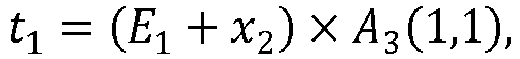
- the application of 1D-DCT with size 3 provides odd lines of the final transform vector, i.e. t 1 t 3 t 5
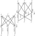
- Such a relationship can be advantageously exploited for computing the product: X 6 ⁇ [ v 1 v 2 v 3 ] t as disclosed by the butterfly diagram shown on the left part of figure 7 .
- the fast implementation of the transform A 6 can be performed using the fast implementation of the transform for size 3 (A 3 ) applied to linear combinations of the input signal (x 1 , x 2 , x 3 , x 4 , x 5 , x 6 ) t to obtain odd lines (t 1 , t 3 , t 5 ) of the transformed vector and the fast implementation of the complementary matrix X 6 applied to linear combinations of the input signal (x 1 , x 2 , x 3 , x 4 , x 5 , x 6 ) t to obtain even lines (t 2 , t 4 , t 6 ) of the transformed signal.
- a similar reasoning can be applied for computing the inverse transform S 6 for size 6.
- P c ( S 6 ) comprises the matrix A 3 t on the top-left 3x3 sub-matrix and the matrix X 6 in the 3x3 top-right sub-matrix.
- P c S 6 2 6 S ′ 3 X 6 S ′ 3 ⁇ ⁇ X 6 ⁇ , where S ′ 3 ⁇ represents the matrix S' 3 in a horizontally flipped version and ⁇ X 6 ⁇ is the opposite of the horizontally flipped version of X 6 .
- the fast implementation of the inverse DCT with size 6 can simply re-use the fast implementation of the inverse DCT with size 3 and the fast implementation of the product by matrix X 6 disclosed above.
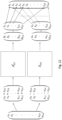
- a compact view of such computations is provided under the form of a butterfly diagram and illustrated on figure 10 .
- a fast implementation of the transform A 12 can be performed using a fast implementation of the transform for size 6 (A 6 ) applied to linear combinations of the input signal (x 1 , x 2 , x 3 , x 4 , x 5 , x 6 , x 7 , x 8 , x 9 , x 10 , x 11 , x 12 ) t to obtain odd lines (t 1 , t 3 , t 5 , t 7 , t 9 , t 11 ) of the transformed vector and the fast implementation of the complementary matrix X 12 disclosed above applied to linear combinations of the input signal (x 1 , x 2 , x 3 , x 4 , x 5 , x 6 , x 7 , x 8 , x 9 , x 10 , x 11 , x 12 ) t to obtain even lines (t 2 , t 4 , t 6 , t 8 ,
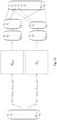
- the fast inverse DCT transform with size 24 can be designed in a recursive fashion by re-using the inverse DCT butterfly method for size 12 and the method provided above for the X 24 matrix operator.
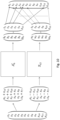
- fast integer DCT transform implementation for block sizes equal to 3 ⁇ 2 n ,n ⁇ 0, i.e. for blocks having a size multiple of 3 in at least one dimension (width, height), can be designed in a recursive way, as illustrated on figure 13 .
- Such fast integer DCT transform implementation for blocks having a size N multiple of 3 in at least one dimension can be designed in a general case, for N > 3, using a butterfly implementation of the transform matrix A N .
- Such a butterfly implementation illustrated on figure 13 is based on a matrix P l ( A N ) wherein the N/2 first lines of P l ( A N ) corresponds to odd lines of A N and N/2 last lines of P l ( A N ) corresponds to even lines of A N .
- a N /2 represents a vertically flipped version of the matrix A N /2
- -X N represents the opposite of the vertically flipped version of a complementary matrix transform X N .
- N is even and ( 2k + 1)(2 j + 1) is odd, ( N - (2 k + 1)(2 j + 1)) is also odd, thus the term cos N ⁇ 2 k + 1 2 j + 1 ⁇ 2 N corresponds to a member of matrix X N located on a line different from ( k + n 4 ).
- Figure 14 illustrates a block diagram of an exemplary decoder according to an embodiment of the present principles.
- a bitstream representative of a coded image or video comprises coded data representative of at least one block of said image or video, wherein said block has been coded according to an embodiment of the present principles.
- coded data is passed to the video decoding modules of the video decoder 30. As illustrated in figure 14 , coded data is passed to an entropy decoding module that performs entropy decoding and delivers quantized coefficients QCOEF' to an inverse quantization module and syntax elements to a prediction module.
- the quantized coefficients QCOEF' are inverse quantized by the inverse quantization module and inverse transformed by an inverse transform module delivering residual blocks data RES'.
- a block to be reconstructed may have been coded with a size equal to 3 ⁇ 2 N in at least one dimension.
- the inverse transform module is configured to operate on such blocks by applying a 2D transform with size 3 ⁇ 2 n in width or height.
- the inverse transform module is thus configured to implement one of the fast inverse 1D DCT transform as disclosed above according to the size of the block.
- the prediction module builds prediction blocks PRED according to the syntax element and using a motion compensation module if a current block has been inter-predicted or an intra prediction module if the current block has been spatially predicted.
- a reconstructed picture I' is obtained by adding prediction blocks PRED and residual blocks RES'.
- the reconstructed picture I' is stored in a reference frame memory for later use as reference frame.
- the reconstructed picture I' is then outputted by the video decoder 30.
- the decoder 30 may be implemented as hardware or software or a combination of hardware and software thereof.
- Figure 15 illustrates a flow diagram of an exemplary method for encoding a video according to an embodiment of the present principles.
- at least one block BLK of a picture of the video has a size N which is not a power of 2 along at least one dimension.
- N is a multiple of 3 and can be written as 3 ⁇ 2 n , n ⁇ 0.
- a predicted block is determined for the current block BLK.
- the predicted block can be determined according to classical block prediction method (intra or inter prediction).
- the predicted block size's is equal to the size of the block BLK.
- a residual block is obtained by computing a difference between the current block BLK and the predicted block.
- the residual block thus, has a size N along at least one dimension.
- step 42 block transform of the residual block is performed.
- the block transform is performed by applying a 2D separable DCT transform, i.e. by applying a 1D DCT transform on the lines of the residual block, and then 1D DCT transform on the columns of the residual block. If the lines, respectively columns, of the residual block have a size equal to 3 ⁇ 2 n , n ⁇ 0, a fast 1D DCT transform implementation as disclosed above is used. Otherwise, if the lines, respectively columns, of the residual block have a size equal to a power of 2, known fast 1D DCT transform implementations are used.
- step 43 the transformed residual block is then quantized and entropy coded.
- Figure 16 illustrates a flow diagram of an exemplary method for decoding a video according to an embodiment of the present principles.
- at least one block BLK of a picture of the video has a size N which is not a power of 2 along at least one dimension.
- N is a multiple of 3 and can be written as 3 ⁇ 2 n , n ⁇ 0.
- the current block BLK is reconstructed as follows.
- a transformed residual block is entropy decoded from a bitstream and inverse quantized.
- the transformed residual block size's is equal to the size of the current block BLK and comprises decoded data for the current block BLK to reconstruct.
- inverse block transform is performed on the transformed residual block.
- the inverse block transform is performed by applying a 2D separable inverse DCT transform, i.e. by applying a 1D inverse DCT transform on the lines of the transformed residual block, and then a 1D inverse DCT transform on the columns of the transformed residual block. If the lines, respectively columns, of the transformed residual block have a size equal to 3 ⁇ 2 n , n ⁇ 0, a fast 1D inverse DCT transform implementation as disclosed above is used. Otherwise, if the lines, respectively columns, of the transformed residual block have a size equal to a power of 2, known fast 1D inverse DCT transform implementations are used.
- Inverse block transform delivers a residual block with a size equals to the size of the transformed residual block.
- a predicted block is determined for the current block BLK to reconstruct.
- the predicted block can be determined according to classical block prediction method (intra ou inter prediction). According to the embodiment disclosed herein, the predicted block has a same size as the current block BLK.
- step 53 the current block BLK is reconstructed by adding the predicted block to the residual block.
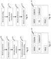
- Figure 17 illustrates an exemplary encoder that may be used in one embodiment of the present principles.
- Such an apparatus for encoding a video is configured to implement the method for encoding a video according to the present principles.
- the encoder apparatus of figure 17 may be as an example the encoder 20 as described in figure 2 .
- the encoder apparatus comprises a processing unit PROC equipped for example with a processor and driven by a computer program PG stored in a memory MEM and implementing the method for encoding a video according to the present principles.
- the code instructions of the computer program PG are for example loaded into a RAM (not shown) and then executed by the processor of the processing unit PROC.
- the processor of the processing unit PROC implements the steps of the method for encoding a video which has been described here above, according to the instructions of the computer program PG.
- the encoder apparatus 20 comprises a communications unit COM to transmit an encoded bitstream to a decoder.
- the encoder apparatus 20 also comprises an interface for receiving a picture to be coded, or a video.
- Figure 18 illustrates an exemplary decoder that may be used in one embodiment of the present principles.
- Such an apparatus for decoding a video is configured to implement the method for decoding a video according to the present principles.
- the decoder apparatus of figure 18 may be as an example the decoder 30 as described in figure 14 .
- the decoder apparatus comprises a processing unit PROC equipped for example with a processor and driven by a computer program PG stored in a memory MEM and implementing the method for decoding a video according to the present principles.
- the code instructions of the computer program PG are for example loaded into a RAM (not shown) and then executed by the processor of the processing unit PROC.
- the processor of the processing unit PROC implements the steps of the method for decoding a video which has been described here above, according to the instructions of the computer program PG.
- the decoder apparatus 30 comprises a communications unit COM to receive an encoded bitstream from an encoder.
- the decoder apparatus 30 also comprises an interface for displaying a reconstructed picture or a reconstructed video.
Landscapes
- Engineering & Computer Science (AREA)
- Multimedia (AREA)
- Signal Processing (AREA)
- Physics & Mathematics (AREA)
- Discrete Mathematics (AREA)
- General Physics & Mathematics (AREA)
- Compression Or Coding Systems Of Tv Signals (AREA)
Description
- A method and an apparatus for encoding a video into a bitstream are disclosed. Corresponding decoding method and apparatus are further disclosed.
- For coding a picture of a video sequence, video compression methods usually divide the picture into a set of blocks of pixels. Each block is then predicted using information already reconstructed, corresponding to the blocks previously encoded / decoded in the current picture. The coding of a current block is performed using an intra or inter prediction of the current block, and a prediction residual or "residual block" corresponding to a difference between the current block and the predicted block is computed. The resulting residual block is then converted, for example by using a transform such as a DCT (discrete cosine transform) type transform. The coefficients of the transformed residual block are then quantized and encoded by entropy coding and transmitted to a decoder.
- In an HEVC video compression standard ("ITU-T H.265 Telecommunication standardization sector of ITU (10/2014), series H: audiovisual and multimedia systems, infrastructure of audiovisual services - coding of moving video, High efficiency video coding, Recommendation ITU-T H.265"), a picture is divided into Coding Tree Units (CTU), which size may be 64x64, 128x128 or 256x256 pixels. Each CTU may be further subdivided using a quad-tree division, where each leaf of the quad-tree is called a Coding Unit (CU). Each CU is then given some Intra or Inter prediction parameters. To do so, a CU is spatially partitioned into one or more Prediction Units (PU), a PU may have a square or a rectangular shape. Each PU is assigned some prediction information, such as for example motion information, spatial intra prediction. According to the HEVC video compression standard, each CU may be further subdivided into Transform Units (TU) for performing the transform of the prediction residual. However, only square supports transform are defined in the HEVC video compression standard, as disclosed on
figure 1A . Onfigure 1A , solid lines indicate CU boundaries and dotted lines indicate TU boundaries. - A Quad-Tree plus Binary-Tree (QTBT) coding tool (" Algorithm Description of Joint Exploration Test Model 3'; Document JVET-C1001_v3, Joint Video Exploration Team of ISO/IEC JTC1/SC29/WG11, 3rd meeting, 26th May-1st June 2015, Geneva, CH) provides a more flexible CTU representation than the CU/PU/TU arrangement of the HEVC standard. The Quad-Tree plus Binary-Tree (QTBT) coding tool consists in a coding tree where coding units can be split both in a quad-tree and in a binary-tree fashion. Such coding tree representation of a Coding Tree Unit is illustrated on
Fig. 1B , where solid lines indicate quad-tree partitioning and dotted lines indicate binary partitioning of a CU. - The splitting of a coding unit is decided on the encoder side through a rate distortion optimization procedure, which consists in determining the QTBT representation of the CTU with minimal rate distortion cost. In the QTBT representation, a CU has either a square or a rectangular shape. The size of coding unit is always a power of 2, and typically goes from 4 to 128. The QTBT decomposition of a CTU is made of two stages: first the CTU is split in a quad-tree fashion, then each quad-tree leaf can be further divided in a binary fashion or in a quad-tree fashion, as illustrated on
fig. 1C , where solid lines represent the quad-tree decomposition phase and dotted lines represent the binary decomposition that is spatially embedded in the quad-tree leaves. With the QTBT representation, a CU is not anymore partitioned into PU or TU. With the QTBT representation, the transform of the prediction residual is performed on blocks of size expressed as a power of 2 and existing separable transform and fast implementation of such transform usually used for square blocks can be re-used. However, such a QTBT representation does not allow for asymmetric splitting of a CU. Patent applicationUS2010/266008 discloses a fast implementation of even sized DCT transforms. - The invention is defined in the set of appended claims.
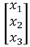
- According to an embodiment, performing block transform of said residual block comprises at least performing butterfly operations converting from a spatial domain to a transform domain a sample vector of
size 3, wherein said butterfly operations implement a transform matrix of size 3x3, said sample vector comprising: - samples of said residual block along said at least one dimension in the case where N equals 3, and
- linear combinations of samples of said residual block taken along said at least one dimension in the case where N is higher than 3.
- According to another embodiment, said block transform is based on a transform matrix AN represented by:

- According to a variant, said method further comprising, for N > 3:
- performing butterfly operations converting from a spatial domain to a transform domain a sample vector of size N/2, wherein said butterfly operations implement a complementary matrix transform XN represented by:

- This embodiment allows providing a fast implementation of the transform when N is higher than 3. Therefore, computational resources are saved.
- According to another embodiment, butterfly operations converting from a spatial domain to a transform domain a sample vector of
size 3 are represented by:
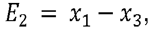


size 3 from said spatial domain,
size 3 from said transform domain, E 1 and E 2 represent intermediate values for butterfly design used for computing samples from said transform domain, A 3(k, j) represent corresponding values of said transform matrix. - Such an implementation allows reducing the number of multiplications needed for performing the transform of the residual block. Thus, complexity is reduced.
- According to another embodiment, butterfly operations converting from a spatial domain to a transform domain a sample vector of
size 6, comprises at least the following operations:


size 6 from said spatial domain, E 1, E 2 and E 3 represent intermediate values for butterfly design further used for computing transformed samples from said transformed residual block, X 6(k, j) represent corresponding values of the complementary matrix transform and
- According to another embodiment, for N > 3, a butterfly implementation of said matrix transform AN is based on a matrix Pl (AN ) corresponding to a matrix wherein N/2 first lines of Pl (AN ) corresponds to odd lines of AN and N/2 last lines of Pl (AN ) corresponds to even lines of AN.
- According to this embodiment, the butterfly implementation for transforming data of blocks having a size N in at least one dimension which is a multiple of 3 takes advantage of the symmetry which is present in the transform matrix AN. Therefore, a butterfly implementation of the transform matrix for a size N/2 can be re-used for the size N.
- According to another embodiment, said matrix Pl (AN ) is represented by:

A N/2 represents a vertically flipped version of the matrix A N/2 , and -XN represents the opposite of the vertically flipped version of said complementary matrix transform XN. - According to this embodiment, it is thus possible to re-use the butterfly implementation designed for the matrix AN/2.
- According to another embodiment, the transform process through matrix Pl (AN ) is performed as 2 sub-transforms A N/2 and XN, respectively applied on sub-vectors derived from input spatial samples (xi + x N+1-i ) i=1,..,N/2 and (xi - x N+1-i ) i=1,..,N/2 .
- According to a further embodiment, the two sub-transforms are performed through butterfly operations of matrix A N/2 applied on a sub-vector (ai ) i=1,..,N/2 = (xi + x N+1-i ) i=1,..,N/2 , leading to a transformed sub-vector (bi ) i=1,...,N/2 on one side, and butterfly operations of matrix XN applied on a sub-vector (vi ) i=1,...N/2 = (xi - x N+1-i ) i=1,..,N/2 , leading to a transformed sub-vector (ui )i=1,...N/2 .
- According to a further embodiment, a final transform vector (ti ) i=1,...,N is obtained as an interleaving of said transformed sub-vectors (bi ) i=1,..,N/2 and (ui ) i=1,...N/2 : (ti ) i=1,...,N = (b 1 ,u 1 , b 2 , u 2 , ..., b N/2 , u N/2)
- According to another aspect of the disclosure, a method for decoding a video is disclosed. Such a method comprises, for at least one block having a size N which is not a power of 2 along at least one dimension:
- decoding a transformed residual block,
- performing inverse block transform of said transformed residual block, said residual block having a size N,
- determining a predicted block for said at least one block,
- reconstructing said at least one block from said inverse transformed residual block and said predicted block.
- Thus, the present principle allows performing inverse transformation of a transformed residual block on a support of a same size as the support for prediction. Thus, asymmetric partitioning of blocks can be coupled to fast inverse transformation of data of such blocks, yielding to better compression efficiency and reducing computational complexity.
- According to an embodiment, N is a multiple of 3.
- According to another embodiment, performing inverse block transform of said transformed residual block comprises at least performing butterfly operations converting from a transform domain to a spatial domain a sample vector of
size 3, wherein said butterfly operations implement a transform matrix of size 3x3, said sample vector comprising: - samples of said transformed residual block along said at least one dimension in the case where N equals 3, and
- linear combinations of samples of said transformed residual block taken along said at least one dimension in the case where N is higher than 3.
- According to another embodiment, said inverse block transform is based on a transform matrix SN represented by:


- According to another embodiment, butterfly operations converting from a transform domain to a spatial domain a sample vector of
size 3 are represented by:


size 3 from said spatial domain,
size 3 from said transform domain, E 1, E 2 and E 3 represent intermediate values for butterfly design used for computing samples from said spatial domain, S 3 (j, k) represent corresponding values of the transform matrix. - Such an implementation allows reducing the number of multiplications needed for performing the inverse transform of the residual block. Thus, complexity is reduced.
- According to another embodiment, said method further comprising, for N > 3:
- performing butterfly operations converting from a transform domain to a spatial domain a sample vector of size N/2, wherein said butterfly operations implement a complementary matrix transform XN represented by:

- This embodiment allows providing a fast implementation of the inverse transform when N is higher than 3. Therefore, computational resources are saved.
- According to another embodiment, butterfly operations converting from a transform domain to a spatial domain a sample vector of
size 6, are represented by:


size 3 from said transform domain, E 1, E 2 and E 3 represent intermediate values for butterfly design further used for computing transformed samples from said transformed residual block, X 6(k, j) represent corresponding values of the complementary matrix transform and
- According to another embodiment, said butterfly operations implementing said matrix transform XN uses linear combinations of columns from said matrix transform XN. This embodiment takes advantage of the properties of the matrix transform XN.
- According to another embodiment, for N > 3, a butterfly implementation of said matrix transform SN is based on a matrix Pc (SN ) corresponding to a matrix wherein N/2 first column of Pc (SN ) corresponds to odd columns of SN and N/2 last columns of Pc (SN ) corresponds to even columns of SN.
- According to this embodiment, the butterfly implementation for transforming data of blocks having a size N in at least one dimension which is a multiple of 3 takes advantage of the symmetry which is present in the transform matrix SN. Therefore, a butterfly implementation of the transform matrix for a size N/2 can be re-used for the size N.
- According to another embodiment, said matrix Pc (SN ) is represented by:


- According to this embodiment, it is thus possible to re-use the butterfly implementation designed for the matrix SN/2.
- According to another embodiment, the transform process through matrix Pc (SN ) is performed as 2 sub-transforms S N/2 and XN, respectively applied on sub-vectors derived from input transform samples (ti ) i=1,..,N/2 and
- According to a further embodiment, the two sub-transforms are performed through butterfly operations of matrix S N/2 applied on a sub-vector (ti ) i=1,..,N/2 , leading to a sub-vector (a'i ) i=1,..,N/2 on one side, and butterfly operations of matrix XN applied on a sub-vector

- According to a further embodiment, a final inverse transformed vector (xi ) i=1,...,N is obtained by recombining said sub-vectors (a' i ) i=1,..,N/2 and (x'i ) i=1,...N/2:

- According to another aspect of the disclosure, an apparatus for encoding a video is disclosed. Such an apparatus comprises, for at least one block having a size N which is not a power of 2 along at least one dimension:
- means for determining a predicted block for said at least one block,
- means for obtaining a residual block from said at least one block and said predicted block,
- means for performing block transform of said residual block, said residual block having a size N,
- means for encoding said transformed residual block.
- According to another aspect of the disclosure, an apparatus for decoding a video is also disclosed. Such an apparatus comprises, for at least one block having a size N which is not a power of 2 along at least one dimension:
- means for decoding a transformed residual block,
- means for performing inverse block transform of said transformed residual block, said residual block having a size N,
- means for determining a predicted block for said at least one block,
- means for reconstructing said at least one block from said inverse transformed residual block and said predicted block.
- The present disclosure also provides a computer readable storage medium having stored thereon instructions for encoding a video according to any one of the embodiments described in the disclosure.
- The present disclosure also provides a computer readable storage medium having stored thereon instructions for decoding a video according to any one of the embodiments described in the disclosure.
- According to one implementation, the different steps of the method for coding a video or decoding a video as described here above are implemented by one or more software programs or software module programs comprising software instructions intended for execution by a data processor of an apparatus for encoding/decoding a video, these software instructions being designed to command the execution of the different steps of the methods according to the present principles.
- A computer program is also disclosed that is capable of being executed by a computer or by a data processor, this program comprising instructions to command the execution of the steps of a method for encoding a video or of the steps of a method for decoding a video as mentioned here above.
- This program can use any programming language whatsoever and be in the form of source code, object code or intermediate code between source code and object code, such as in a partially compiled form or any other desirable form whatsoever.
- The information carrier can be any entity or apparatus whatsoever capable of storing the program. For example, the carrier can comprise a storage means such as a ROM, for example a CD ROM or a microelectronic circuit ROM or again a magnetic recording means, for example a floppy disk or a hard disk drive.
- Again, the information carrier can be a transmissible carrier such as an electrical or optical signal which can be conveyed via an electrical or optical cable, by radio or by other means. The program according to the present principles can be especially uploaded to an Internet type network.
- As an alternative, the information carrier can be an integrated circuit into which the program is incorporated, the circuit being adapted to executing or to being used in the execution of the methods in question.
- According to one embodiment, the methods/apparatus may be implemented by means of software and/or hardware components. In this respect, the term "module" or "unit" can correspond in this document equally well to a software component and to a hardware component or to a set of hardware and software components.
- A software component corresponds to one or more computer programs, one or more sub-programs of a program or more generally to any element of a program or a piece of software capable of implementing a function or a set of functions as described here below for the module concerned. Such a software component is executed by a data processor of a physical entity (terminal, server, etc) and is capable of accessing hardware resources of this physical entity (memories, recording media, communications buses, input/output electronic boards, user interfaces, etc).
- In the same way, a hardware component corresponds to any element of a hardware unit capable of implementing a function or a set of functions as described here below for the module concerned. It can be a programmable hardware component or a component with an integrated processor for the execution of software, for example an integrated circuit, a smartcard, a memory card, an electronic board for the execution of firmware, etc.
-
-
Figure 1A illustrates an exemplary CTU partitioning into coding units and transform units according to an HEVC video compression standard, -
Figure 1B illustrates an exemplary CTU partitioning according to the quad-tree and binary tree based method (QTBT), -
Figure 1C illustrates an exemplary tree representation of a CTU partitioning according to the quad-tree and binary tree based method (QTBT), -
Figure 2 illustrates a block diagram of an exemplary encoder according to an embodiment of the present principles, -
Figure 3 illustrates example of partitioning of a CU into sub-CUs according to the present principles, -
Figure 4 illustrates a diagram of a butterfly implementation of a one-dimensional transform with size equal to 3, according to an embodiment of the present principles, -
Figure 5 illustrates another diagram of a butterfly implementation of a one-dimensional transform with size equal to 3, according to an embodiment of the present principles, -
Figure 6 illustrates a diagram of a butterfly implementation of a one-dimensional inverse transform with size equal to 3, according to an embodiment of the present principles, -
Figure 7 illustrates a diagram of a butterfly implementation of a one-dimensional complementary transform with size equal to 3 used for performing a one-dimensional fast transform with size equal to 6, according to an embodiment of the present principles, -
Figure 8 illustrates a diagram of a butterfly implementation of a one-dimensional transform with size equal to 6, according to an embodiment of the present principles, -
Figure 9 illustrates the relationships between lines and columns of X12 exploited in the fast implementation of X12. -
Figure 10 illustrates a diagram of a one-dimensional transform implementation with size equal to 12 according to an embodiment of the present principles, -
Figure 11 illustrates a diagram of a butterfly implementation of a one-dimensional complementary transform with size equal to 6 used for performing a one-dimensional fast transform with size equal to 12, according to an embodiment of the present principles, -
Figure 12 illustrates a diagram of a one-dimensional transform implementation with size equal to 24 according to an embodiment of the present principles, -
Figure 13 illustrates a diagram of a one-dimensional transform implementation with size equal to N according to an embodiment of the present principles, -
Figure 14 illustrates a block diagram of an exemplary decoder according to an embodiment of the present principles, -
Figure 15 illustrates a flow diagram of an exemplary method for encoding a video according to an embodiment of the present principles, -
Figure 16 illustrates a flow diagram of an exemplary method for decoding a video according to an embodiment of the present principles, -
Figure 17 illustrates an exemplary encoder that may be used in one embodiment of the present principles, -
Figure 18 illustrates an exemplary decoder that may be used in one embodiment of the present principles. - It is to be understood that the figures and descriptions have been simplified to illustrate elements that are relevant for a clear understanding of the present principles, while eliminating, for purposes of clarity, many other elements found in typical encoding and/or decoding devices. It will be understood that, although the terms first and second may be used herein to describe various elements, these elements should not be limited by these terms. These terms are only used to distinguish one element from another. Various methods are described above, and each of the methods comprises one or more steps or actions for achieving the described method. Unless a specific order of steps or actions is required for proper operation of the method, the order and/or use of specific steps and/or actions may be modified or combined. A picture is an array of luma samples in monochrome format or an array of luma samples and two corresponding arrays of chroma samples in 4:2:0, 4:2:2, and 4:4:4 colour format. Generally, a "block" addresses a specific area in a sample array (e.g., luma Y), and a "unit" includes the collocated block of all encoded color components (Y, Cb, Cr, or monochrome). However, the term "block" is used herein to refer to a block (e.g. a CB, a CTB) or a unit (e.g. a CU, a CTU).
In the following sections, the word "reconstructed" and "decoded" can be used interchangeably. Usually but not necessarily "reconstructed" is used on the encoder side while "decoded" is used on the decoder side. -
Figure 2 illustrates a block diagram of an exemplary encoder according to an embodiment of the present principles. Thevideo encoder 20 disclosed here below may be conforming to any video or still picture encoding schemes. The encoding and decoding processes described below are for illustration purposes. According to some embodiments, encoding or decoding modules may be added, or removed or may vary from the following modules. However, the principle disclosed herein could still be applied to these variants. - Classically, the
video encoder 20 may include several modules for block-based video encoding, as illustrated infigure 2 . A picture I to be encoded is input to theencoder 20. The picture I is first subdivided into a set of blocks by a subdividing module. Each block BLK of the picture I is then processed for encoding. A block BLK may have size ranging from 4x4 to 128x128 pixels. Usually but not necessarily, the size of a block BLK is a power of 2. - The
encoder 20 performs encoding of each block BLK of the picture I as follows. Theencoder 20 comprises a mode selection unit for selecting a coding mode for a block BLK of the picture to be coded, e.g. based on a rate/distorsion optimization. Such a mode selection unit comprising: - a motion estimation module for estimating motion between one current block of the picture to be coded and reference pictures,
- a motion compensation module for predicting the current block using the estimated motion,
- an intra prediction module for spatially predicting the current block.
- The mode selection unit may also decide whether splitting of the block is needed according to rate/distorsion optimization for instance. In that case, the mode selection unit then operates on each subblock of the block BLK. Each subblock of the block BLK may also be further split into subblocks.
- Once a coding mode is selected for the current block BLK or coding modes for subblocks of the current block BLK are selected, the mode selection unit delivers a predicted block PRED and corresponding syntax elements to be coded in the bitstream for performing the same block prediction at a decoder. When the current block BLK has been split, the predicted block PRED is formed by the set of predicted subblocks delivered by the mode selection unit for each subblocks.
- A residual block RES is then obtained by substracting the predicted block PRED from the original block BLK.
- The residual block RES is then transformed by a transform processing module delivering a transform block TCOEF of transformed coefficients. The transform block TCOEF is then quantized by a quantization module delivering a quantized transform block QCOEF of quantized residual transform coefficients.
- The syntax elements and quantized residual transform coefficients of the block QCOEF are then input to an entropy coding module to deliver coded data to form the coded bitstream STR.
- The quantized residual transform coefficients of the quantized transform block QCOEF are processed by an inverse quantization module delivering a block TCOEF' of unquantized transform coefficients. The block TCOEF' is passed to an inverse transform module for reconstructing a block of residual prediction RES'.
- A reconstructed version REC of the block BLK is then obtained by adding the prediction block PRED to the reconstructed residual prediction block RES'.
- The reconstructed block REC is stored in memory for use by a picture reconstruction module. The picture reconstruction module performs reconstruction of a decoded version I' of the picture I from the reconstructed blocks REC. The reconstructed picture I' is then stored in a reference picture memory for later use as a reference picture for encoding the following pictures of the set of pictures to code or for encoding subsequent blocks of the picture I.
- According to an embodiment of the present principles, when determining a coding mode for coding a block BLK, the block BLK or subblocks of the block BLK may be asymmetrically split as illustrated by
figure 3 . Such splittings result in blocks having rectangular shapes. These shapes consist in sizes equal to 3×2N in width and/or height. Furthermore, a block or subblock having a size multiple of 3 in width or height can be further split in a binary fashion, i.e. horizontally or vertically. As a consequence, a square block of size (w, h), where w is the width of the block, and h is its height, that is split through one of the asymmetric binary splitting modes would lead for example to 2 subblocks with respective rectangular sizes (
- According to the present principle, the transform processing module is configured to operate on such rectangular shapes by applying a 2D transform with
size 3 · 2 n in width or height. Such process does not exist in known video coding standards because only square transforms are allowed. According to the present principles, the transform processing module is thus configured to operate on a block having a same shape and size as the shape and size of the prediction block used for predicting the block. Therefore, no more partitioning into transform unit is needed. - The present principle allows providing a fast implementation of the 2D transform to apply on blocks having a size multiple of 3 in at least one dimension (width, height) is disclosed below. According to the present principle, a fast implementation of the 2D inverse transform to apply on blocks having a size multiple of 3 in at least one dimension (width, height) is also disclosed below. The inverse transform module disclosed above is configured to apply such a fast 2D transform to the blocks having a size multiple of 3 in at least one dimension.
- The 2D transform applied on a block in standard video codec is a 2D DCT like transform. The 2D DCT applied on a block in standard video codec involves the separable application of two 1D transforms onto the considered 2D block, in horizontal and vertical directions.
- If we defined the following matrix AN for a given size N, as follows:


- Then the 2D separable DCT of an input square block X with size N × N can be written as follows:


- Thus it consists in applying the one-dimensional DCT transform successively on each line and each column of the input two-dimensional block.
- The one-dimensional DCT transform of a one-dimensional vector


- The straightforward implementation of this 1D DCT transform under the form of the multiplication of a matrix by a vector involves N multiplications and N -1 additions, which is a significant amount of operations when the input vector is of large size such as for example 32, 64, 128, 256.
- To limit the complexity of integer DCT transform implementation, it is advantageous to design a fast implementation of such transform. A fast implementation of the 1D- DCT transform is disclosed for block sizes equal to 3 · 2 n, n ≥ 0, i.e. for blocks having a size multiple of 3 in at least one dimension (width, height).
- The DCT matrix for a vector size equal to 3 is given by:

- So,


- Butterfly implementations for matrix transform and inverse matrix transform with
size 3 Therefore, a butterfly implementation of the one-dimension DCT withsize 3 is shown onfigure 4 . - On
figure 4 , the graph nodes on the left correspond to input samples, and the nodes on the right are the resulting transform DCT coefficients. The values associated with each edge represent a multiplicative factor, which are called edge factors. Moreover, edges that arrive at a same right side node are summed together. Where the same multiplicative factor is applied on some edges that go to same right-side node, then the addition is done before the multiplication by the edge factor. - An equivalent, slightly less compact view of the same butterfly implementation of
figure 4 is illustrated onfigure 5 . - Therefore, a fast implementation of the 1D DCT with
size 3 is as follows: -
-

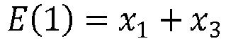
-

-

- t 3 = E(1) × A 3(3,1) - x 2, where E(1) and E(2) represent intermediate nodes on the butterfly diagram shown on
figure 5 . - Such a butterfly implementation involves 4 additions and 3 multiplications, while a classical matrix-based DCT implementation involves 6 additions and 9 multiplications.
- Below, a butterfly diagram for computing the inverse transform 1D DCT with size equal to 3 is shown. The DCT matrix is orthogonal, which implies that the inverse transform matrix S3 can be computed from the transform matrix A3 as follows:

- A butterfly implementation for S3 is shown on
figure 6 . Onfigure 6 , terms of matrix A are referred to while A 3(1,1) = S 3(1,1), A 3(2,1) = S 3(1,2) and A 3(3,1) = S 3(1,3). - Therefore, a fast implementation of the 1D inverse DCT with
size 3 is as follows: -

-

-

-

-

-

- Such a butterfly implementation involves 5 additions and 3 multiplications, instead of 6 additions and 9 multiplications for the classical matrix-based implementation.
- Below, butterfly implementations equivalent to matrix transform and inverse matrix transform with a size equal to 6 are disclosed.
- The matrix transform corresponding to the 1D DCT with
size 6 based on the matrix AN is as follows:
- A6 can also be written as follows:

- It appears from A6 that the odd lines of A 6 comprises the coefficients of A3 discussed above. Therefore, a matrix Pl can be written as follows by permutating lines of A6 :

- In the matrix Pl (A 6), the first 3 lines correspond to odd lines of A6 and the last 3 lines correspond to even lines of A6.
- Pl (A 6) can thus be re-written using A3 and a complementary matrix transform X6, as:


- Therefore, the 1D DCT of size 6 applied to a 1D sample vector


size 6 can be performed by performing the computation of the fast 1D DCT withsize 3 disclosed above applied to a linear combination of samples of the input vector X and by performing a fast computation of a product of the matrix X 6 by a 3 × 1 vector comprising linear combination of samples of the input vector X. The application of 1D-DCT withsize 3 provides odd lines of the final transform vector, i.e.
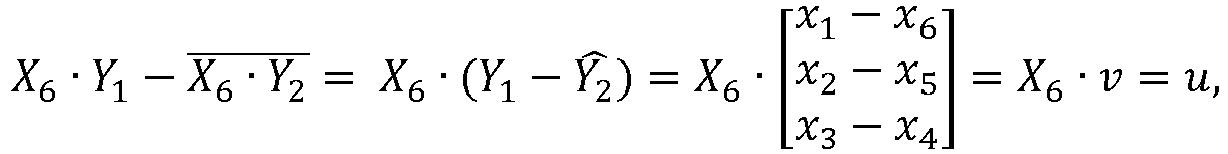
- Below is disclosed a fast implementation of such multiplication of the matrix X 6 by a 3 × 1 vector V=[v 1 v 2 v 3] t, where [v 1 v 2 v 3] = [x 1 - x 6 , x 2 - x 5 , x 3 - x 4].
- A way of implementing the product of X 6 by a vector V=[v 1 v 2 v 3] t is:
-

-

-

- Such an implementation leads to 7 multiplications and 6 additions.
- It can be noted that:
-

- Therefore, the following relationship between the values of the cosinus function can be define:

- Such a relationship can be advantageously exploited for computing the product:
X 6 · [v 1 v 2 v 3] t as disclosed by the butterfly diagram shown on the left part offigure 7 . Such a butterfly diagram is designed to implement the following computational steps:


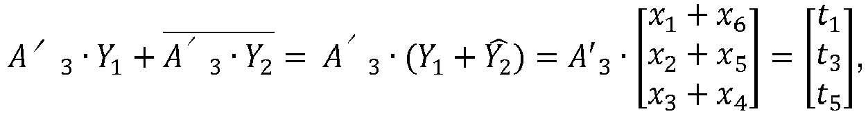
- The fast implementation of X6 disclosed above can be advantageously used in the computation of the second part of the transform matrix A6 ( X 6 · Y 1 -
X 6 · Y 2 ), as follows: -

-

-

-

-

-

- This fast butterfly version of the transform matrix X6 leads to 5 multiplications and 6 additions, instead of 9 multiplications and 6 additions for the straightforward matrix product.
- The overall butterfly design for the one-dimension DCT with
size 6 is shown onfigure 8 . - On
figure 8 , it appears that the fast implementation of the transform A6 can be performed using the fast implementation of the transform for size 3 (A3) applied to linear combinations of the input signal (x1, x2, x3, x4, x5, x6)t to obtain odd lines (t1, t3, t5) of the transformed vector and the fast implementation of the complementary matrix X6 applied to linear combinations of the input signal (x1, x2, x3, x4, x5, x6)t to obtain even lines (t2, t4, t6) of the transformed signal. - A similar reasoning can be applied for computing the inverse transform S 6 for
size 6. As A6 is orthogonal: A 6 -1 = A6 t, so:
- From S 6, it appears that the odd columns of S 6 comprises the coefficients of A 3 -1, so by permutating columns in the matrix S 6, we obtain:

- Pc (S 6) comprises the matrix A 3 t on the top-left 3x3 sub-matrix and the matrix X 6 in the 3x3 top-right sub-matrix. Thus:


- Thus, the fast implementation of the inverse DCT with
size 6 can simply re-use the fast implementation of the inverse DCT withsize 3 and the fast implementation of the product by matrix X 6 disclosed above. - Once these sub-processes are performed, two resulting sub-vectors are obtained:

size 6 is obtained by gathering the sub-vectors as follows:
- Therefore, a fast implementation of the 1D inverse DCT with
size 6, applied on a vector (t1, t2, t3, t4, t5, t6)t in the transform domain , is as follows : -

-

-

-

-

-

-

-

-

-

-

-

- Butterfly implementations for matrix transform and inverse matrix transform with
size 12 - Below, butterfly implementations for matrix transform and inverse matrix transform with a size equal to 12 are disclosed.
- The 1D DCT as applied on a 12x1 vector is obtained through the matrix:

- By grouping odd lines on one side and even lines on the other side, and by permutating lines of the matrix A12, one obtains:

- In other words, X 12 is the matrix of cosine values applied on the values contained in the following matrix:

- Such a matrix can be simplified as:

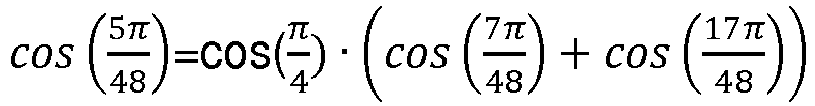
- To implement a fast version of the product X 12 × [v 1 v 2 ··· v 12] t , we exploit the following relationships of the cosine function:
-

-

-
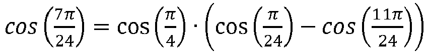
-

-

-

-

- Therefore, these properties are used to establish relationships between the lines and columns of X 12, as illustrated on
figure 9 . From the above equations, one can deduce how some lines of matrix X 12 can be expressed as a linear combination of other lines of X12. Onfigure 9 , the signs on the top of the matrix indicate if the linear combination is multiplied by -1 or not to obtain the destination value. - The relationships between the lines of X 12 illustrated on
figure 9 are further disclosed below: -

-

-

-

-

-

- Therefore, a fast implementation of the product of X 12 by a 6x1 vector V = [v 1 v 2 v 3 v 4 v 5 v 6] t comprises the following operations:
-

-

-

-

-

-

-

-

-

-

-

-

-

-

-

-

- A compact view of such computations is provided under the form of a butterfly diagram and illustrated on
figure 10 . - Therefore, a fast implementation of the transform A12, as illustrated on
figure 11 , can be performed using a fast implementation of the transform for size 6 (A6) applied to linear combinations of the input signal (x1, x2, x3, x4, x5, x6, x7, x8, x9, x10, x11, x12)t to obtain odd lines (t1, t3, t5, t7, t9, t11 ) of the transformed vector and the fast implementation of the complementary matrix X12 disclosed above applied to linear combinations of the input signal (x1, x2, x3, x4, x5, x6, x7, x8, x9, x10, x11, x12)t to obtain even lines (t2, t4, t6, t8, t10, t12) of the transformed signal, with t2, t6, t10, t4, t8, t12 corresponding respectively to the output signal (u1, u2, u3, u4, u5, u6) product of X12 disclosed above. - In the same way as for the inverse DCT with
size 6, the inverse DCT forsize 12 is obtained with the following matrix:
- In the same way as disclosed above, it can be shown that:

size 12 can be determined recursively by re-using the fast implementation of the inverse DCT withsize 6 and the previously described multiplication by matrix X12. - Once these sub-processes at
size 6 are done the inverse transform atsize 12 is obtained by combining the resulting sub-results withsize 6 in the same way as already presented for the butterfly implementation of the inverse transform with size 6:
- Where:


- Butterfly implementations for matrix transform and inverse matrix transform with
size 12 - Below the fast implementation of the DCT transform with size 24, according to the present invention is disclosed. A compact view of such computations is illustrated on
figure 12 . - The butterfly version of DCT with size 24 is constructed in a similar way as for the
size 12. First, if the DCT matrix for size 24 is noted:
- Then it can be shown that:


- The matrix X 24 can be written as:

- if we define the cosine of a matrix M = (mij ) i,j∈[1,n] as the matrix cos(M) = (cos(mij )) i,j∈[1,n]. Linear relationship that exist between lines and columns in the matrix X 24 are identified as follows:
-

-

-

-
-

-

-

-

-

-

- The following linear dependencies between lines and columns are advantageously used to perform the DCT with size 24 as follows:
-

-

-
-

-

-

-

-

-

-

-

-

- A similar construction as for the inverse DCT with
size 12 can be used for determining the inverse DCT transform with size 24. It can thus be shown that:
- Thus, the fast inverse DCT transform with size 24 can be designed in a recursive fashion by re-using the inverse DCT butterfly method for
size 12 and the method provided above for the X 24 matrix operator. - The principle has been disclosed above for fast DCT transform with size equals to 3, 6, 12 and 24. In a more general case, a fast integer DCT transform implementation for block sizes equal to 3 · 2 n,n ≥ 0, i.e. for blocks having a size multiple of 3 in at least one dimension (width, height), can be designed in a recursive way, as illustrated on
figure 13 . - Such fast integer DCT transform implementation for blocks having a size N multiple of 3 in at least one dimension can be designed in a general case, for N > 3, using a butterfly implementation of the transform matrix AN. Such a butterfly implementation illustrated on
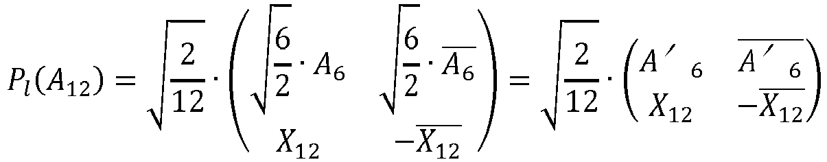
figure 13 is based on a matrix Pl (AN ) wherein the N/2 first lines of Pl (AN ) corresponds to odd lines of AN and N/2 last lines of Pl (AN ) corresponds to even lines of AN. - Furthermore, the matrix Pl (AN ) can be represented by:

A N/2 represents a vertically flipped version of the matrix A N/2 , and-XN represents the opposite of the vertically flipped version of a complementary matrix transform XN. Thus, it is possible to re-use the butterfly implementation designed for the matrix AN/2 by applying the fast implementation of the transform for size N/2 (AN/2) applied to linear combinations of the input signal (xi)t i=1,N-1 to obtain odd lines of the transformed vector. - The complementary matrix transform XN is represented by:

- Thanks to the properties of the cosine function, dependencies between lines and columns of the matrix XN can be determined and advantageously used for designing a fast implementation of XN to be applied to linear combinations of the input signal (xi)t i=i,N-1 to obtain odd lines of the transformed signal.
- These linear dependencies between lines and columns of XN result from the following generic relationship:

- Since N is even and (2k + 1)(2j + 1) is odd, (N - (2k + 1)(2j + 1)) is also odd, thus the term


-
Figure 14 illustrates a block diagram of an exemplary decoder according to an embodiment of the present principles. A bitstream representative of a coded image or video comprises coded data representative of at least one block of said image or video, wherein said block has been coded according to an embodiment of the present principles. - The coded data is passed to the video decoding modules of the
video decoder 30. As illustrated infigure 14 , coded data is passed to an entropy decoding module that performs entropy decoding and delivers quantized coefficients QCOEF' to an inverse quantization module and syntax elements to a prediction module. - The quantized coefficients QCOEF' are inverse quantized by the inverse quantization module and inverse transformed by an inverse transform module delivering residual blocks data RES'. A block to be reconstructed may have been coded with a size equal to 3×2N in at least one dimension. According to the present principle, the inverse transform module is configured to operate on such blocks by applying a 2D transform with
size 3 · 2 n in width or height. The inverse transform module is thus configured to implement one of the fast inverse 1D DCT transform as disclosed above according to the size of the block. - The prediction module builds prediction blocks PRED according to the syntax element and using a motion compensation module if a current block has been inter-predicted or an intra prediction module if the current block has been spatially predicted.
- A reconstructed picture I' is obtained by adding prediction blocks PRED and residual blocks RES'. The reconstructed picture I' is stored in a reference frame memory for later use as reference frame. The reconstructed picture I' is then outputted by the
video decoder 30. - The
decoder 30 may be implemented as hardware or software or a combination of hardware and software thereof. -
Figure 15 illustrates a flow diagram of an exemplary method for encoding a video according to an embodiment of the present principles. According to this embodiment, at least one block BLK of a picture of the video has a size N which is not a power of 2 along at least one dimension. - According to a particular embodiment, N is a multiple of 3 and can be written as 3 · 2 n , n ≥ 0. In
step 40, a predicted block is determined for the current block BLK. The predicted block can be determined according to classical block prediction method (intra or inter prediction). According to the embodiment disclosed herein, the predicted block size's is equal to the size of the block BLK. - In
step 41, a residual block is obtained by computing a difference between the current block BLK and the predicted block. The residual block, thus, has a size N along at least one dimension. - In
step 42, block transform of the residual block is performed. The block transform is performed by applying a 2D separable DCT transform, i.e. by applying a 1D DCT transform on the lines of the residual block, and then 1D DCT transform on the columns of the residual block. If the lines, respectively columns, of the residual block have a size equal to 3 · 2 n , n ≥ 0, a fast 1D DCT transform implementation as disclosed above is used. Otherwise, if the lines, respectively columns, of the residual block have a size equal to a power of 2, known fast 1D DCT transform implementations are used. - In
step 43, the transformed residual block is then quantized and entropy coded. -
Figure 16 illustrates a flow diagram of an exemplary method for decoding a video according to an embodiment of the present principles. According to this embodiment, at least one block BLK of a picture of the video has a size N which is not a power of 2 along at least one dimension. - According to a particular embodiment, N is a multiple of 3 and can be written as 3 · 2 n , n ≥ 0.
- The current block BLK is reconstructed as follows.
- In
step 50, a transformed residual block is entropy decoded from a bitstream and inverse quantized. The transformed residual block size's is equal to the size of the current block BLK and comprises decoded data for the current block BLK to reconstruct. - In
step 51, inverse block transform is performed on the transformed residual block. The inverse block transform is performed by applying a 2D separable inverse DCT transform, i.e. by applying a 1D inverse DCT transform on the lines of the transformed residual block, and then a 1D inverse DCT transform on the columns of the transformed residual block. If the lines, respectively columns, of the transformed residual block have a size equal to 3 · 2 n , n ≥ 0, a fast 1D inverse DCT transform implementation as disclosed above is used. Otherwise, if the lines, respectively columns, of the transformed residual block have a size equal to a power of 2, known fast 1D inverse DCT transform implementations are used. - Inverse block transform delivers a residual block with a size equals to the size of the transformed residual block.
- In
step 52, a predicted block is determined for the current block BLK to reconstruct. The predicted block can be determined according to classical block prediction method (intra ou inter prediction). According to the embodiment disclosed herein, the predicted block has a same size as the current block BLK. - In
step 53, the current block BLK is reconstructed by adding the predicted block to the residual block. -
Figure 17 illustrates an exemplary encoder that may be used in one embodiment of the present principles. Such an apparatus for encoding a video is configured to implement the method for encoding a video according to the present principles. The encoder apparatus offigure 17 may be as an example theencoder 20 as described infigure 2 . - In the example shown in
figure 17 , the encoder apparatus comprises a processing unit PROC equipped for example with a processor and driven by a computer program PG stored in a memory MEM and implementing the method for encoding a video according to the present principles. - At initialization, the code instructions of the computer program PG are for example loaded into a RAM (not shown) and then executed by the processor of the processing unit PROC. The processor of the processing unit PROC implements the steps of the method for encoding a video which has been described here above, according to the instructions of the computer program PG.
- Optionally, the
encoder apparatus 20 comprises a communications unit COM to transmit an encoded bitstream to a decoder. - The
encoder apparatus 20 also comprises an interface for receiving a picture to be coded, or a video. -
Figure 18 illustrates an exemplary decoder that may be used in one embodiment of the present principles. Such an apparatus for decoding a video is configured to implement the method for decoding a video according to the present principles. The decoder apparatus offigure 18 may be as an example thedecoder 30 as described infigure 14 . - In the example shown in
figure 18 , the decoder apparatus comprises a processing unit PROC equipped for example with a processor and driven by a computer program PG stored in a memory MEM and implementing the method for decoding a video according to the present principles. - At initialization, the code instructions of the computer program PG are for example loaded into a RAM (not shown) and then executed by the processor of the processing unit PROC. The processor of the processing unit PROC implements the steps of the method for decoding a video which has been described here above, according to the instructions of the computer program PG.
- Optionally, the
decoder apparatus 30 comprises a communications unit COM to receive an encoded bitstream from an encoder. - The
decoder apparatus 30 also comprises an interface for displaying a reconstructed picture or a reconstructed video.
Claims (14)
- A method for encoding a video comprising, for at least one block having a size N along at least one dimension, wherein N is a multiple of 3:- determining (40) a predicted block for said at least one block;- obtaining (41) a residual block from said at least one block and said predicted block;- performing (42) block transform of said residual block,wherein said block transform involves separate application of 1D horizontal transform and 1D vertical transform,wherein said 1D horizontal or vertical transform is performed by using operations converting from a spatial domain to a transform domain a sample vector of size 3, said operations implemented by:


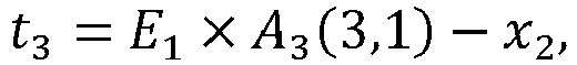

 - encoding (43) said transformed residual block.
 - The method for encoding according to claim 1, wherein said operations implement a transform matrix of size 3x3, said sample vector comprising:- a line or a column of samples of said residual block in the case where N equals 3, and- linear combinations of samples taken from a line or a column of said residual block in the case where N is higher than 3.
- A method according to any one of claims 1 to 2, wherein said block transform is based on a transform matrix AN represented by:


- The method according to claim 3, said method further comprising, for N > 3:- performing butterfly operations converting from a spatial domain to a transform domain a sample vector of size N/2, wherein said butterfly operations implement a complementary matrix transform XN represented by:

- The method according to claim 4, wherein butterfly operations converting from a spatial domain to a transform domain a sample vector of size 6, comprises at least the following operations:


- The method according to claim 3, wherein, for N > 3, a butterfly implementation of said matrix transform AN is based on a matrix Pl (AN ) corresponding to a matrix wherein N/2 first lines of Pl (AN ) corresponds to odd lines of AN and N/2 last lines of Pl (AN ) corresponds to even lines of AN .
- The method according to claim 4 or 6, wherein said matrix Pl (AN ) is represented by:

A N/2 represents a vertically flipped version of the matrix A N/2 , and-XN represents an opposed vertically flipped version of said complementary matrix transform XN. - A method for decoding a video comprising, for at least one block having a size N along at least one dimension, wherein N is a multiple of 3:- decoding (50) a transformed residual block;- performing (51) inverse block transform of said transformed residual block,
wherein said inverse block transform involves separate application of 1D horizontal inverse transform and 1D vertical inverse transform, wherein said 1D horizontal or vertical inverse transform is performed by using operations converting from a transform domain to a spatial domain a sample vector of size 3, said operations implemented by:


 - determining (52) a predicted block for said at least one block; and- reconstructing (53) said at least one block from said inverse transformed residual block and said predicted block.
 - The method according to claim 1 or 8, wherein said operations implement a transform matrix of size 3x3, said sample vector comprising:- a line or a column of samples of said transformed residual block in the case where N equals 3, and- linear combinations of samples taken from a line or a column of said transformed residual block in the case where N is higher than 3.
- A method according to any one of claims 8 to 9, wherein said inverse block transform is based on a transform matrix SN represented by:

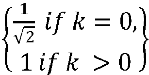
- The method according to claim 10, said method further comprising, for N > 3:- performing butterfly operations converting from a transform domain to a spatial domain a sample vector of size N/2, wherein said butterfly operations implement a complementary matrix transform XN represented by:

- The method according to claim 11, wherein butterfly operations converting from a transform domain to a spatial domain a sample vector of size 6, comprises at least the following operations:


- An apparatus for encoding a video comprising, for at least one block having a size N along at least one dimension, wherein N is a multiple of 3:- means for determining a predicted block for said at least one block;- means for obtaining a residual block from said at least one block and said predicted block;- means for performing block transform of said residual block,wherein said block transform involves separate application of 1D horizontal transform and 1D vertical transform,wherein said 1D horizontal or vertical transform is performed by using operations converting from a spatial domain to a transform domain a sample vector of size 3, said operations implemented by:


 - means for encoding said transformed residual block.
 - An apparatus for decoding a video comprising, for at least one block having a size N along at least one dimension, wherein N is a multiple of 3:- means for decoding a transformed residual block;- means for performing inverse block transform of said transformed residual block, wherein said inverse block transform involves separate application of 1D horizontal inverse transform and 1D vertical inverse transform, wherein said 1D horizontal or vertical inverse transform is performed by using operations converting from a transform domain to a spatial domain a sample vector of size 3, said operations implemented by:


 - means for determining a predicted block for said at least one block; and- means for reconstructing said at least one block from said inverse transformed residual block and said predicted block.
Applications Claiming Priority (2)
| Application Number | Priority Date | Filing Date | Title |
|---|---|---|---|
| EP16306309.2A EP3306937A1 (en) | 2016-10-05 | 2016-10-05 | Method and apparatus for encoding and decoding a video |
| PCT/EP2017/075326 WO2018065511A1 (en) | 2016-10-05 | 2017-10-05 | Method and apparatus for encoding and decoding a video |
Publications (2)
| Publication Number | Publication Date |
|---|---|
| EP3523974A1 EP3523974A1 (en) | 2019-08-14 |
| EP3523974B1 true EP3523974B1 (en) | 2024-02-07 |
Family
ID=57138018
Family Applications (2)
| Application Number | Title | Priority Date | Filing Date |
|---|---|---|---|
| EP16306309.2A Withdrawn EP3306937A1 (en) | 2016-10-05 | 2016-10-05 | Method and apparatus for encoding and decoding a video |
| EP17777919.6A Active EP3523974B1 (en) | 2016-10-05 | 2017-10-05 | Method and apparatus for encoding and decoding a video |
Family Applications Before (1)
| Application Number | Title | Priority Date | Filing Date |
|---|---|---|---|
| EP16306309.2A Withdrawn EP3306937A1 (en) | 2016-10-05 | 2016-10-05 | Method and apparatus for encoding and decoding a video |
Country Status (3)
| Country | Link |
|---|---|
| US (1) | US10735732B2 (en) |
| EP (2) | EP3306937A1 (en) |
| WO (1) | WO2018065511A1 (en) |
Families Citing this family (5)
| Publication number | Priority date | Publication date | Assignee | Title |
|---|---|---|---|---|
| WO2019102889A1 (en) * | 2017-11-24 | 2019-05-31 | ソニー株式会社 | Image processing device and method |
| US11336919B2 (en) * | 2018-03-30 | 2022-05-17 | Sony Corporation | Image processing apparatus and method |
| US20220060723A1 (en) * | 2018-07-06 | 2022-02-24 | Sony Corporation | Image processing device, image processing method, and image processing program |
| CN109600612B (en) * | 2018-10-26 | 2021-10-26 | 西安科锐盛创新科技有限公司 | Method and apparatus for image encoding |
| US11785254B2 (en) * | 2020-05-29 | 2023-10-10 | Tencent America LLC | Implicit mode dependent primary transforms |
Family Cites Families (19)
| Publication number | Priority date | Publication date | Assignee | Title |
|---|---|---|---|---|
| WO1998034195A1 (en) | 1997-01-30 | 1998-08-06 | Yissum Research Development Company Of The Hebrew University Of Jerusalem | Generalized panoramic mosaic |
| US7308131B2 (en) | 2002-12-03 | 2007-12-11 | Ntt Docomo, Inc. | Representation and coding of panoramic and omnidirectional images |
| US7336299B2 (en) | 2003-07-03 | 2008-02-26 | Physical Optics Corporation | Panoramic video system with real-time distortion-free imaging |
| US7627194B2 (en) | 2004-08-13 | 2009-12-01 | Samsung Electronics Co., Ltd. | Method and device for making virtual image region for motion estimation and compensation of panorama image |
| JP5112333B2 (en) | 2006-01-05 | 2013-01-09 | テレフオンアクチーボラゲット エル エム エリクソン(パブル) | Managing media container files |
| US20100172409A1 (en) * | 2009-01-06 | 2010-07-08 | Qualcom Incorporated | Low-complexity transforms for data compression and decompression |
| US9110849B2 (en) * | 2009-04-15 | 2015-08-18 | Qualcomm Incorporated | Computing even-sized discrete cosine transforms |
| US9378185B2 (en) * | 2010-09-30 | 2016-06-28 | Texas Instruments Incorporated | Transform and quantization architecture for video coding and decoding |
| US20120177111A1 (en) | 2011-01-12 | 2012-07-12 | Matthias Narroschke | Efficient clipping |
| US20130083855A1 (en) | 2011-09-30 | 2013-04-04 | Dane P. Kottke | Adaptive color space selection for high quality video compression |
| EP2645713A1 (en) | 2012-03-30 | 2013-10-02 | Alcatel Lucent | Method and apparatus for encoding a selected spatial portion of a video stream |
| WO2014005297A1 (en) | 2012-07-04 | 2014-01-09 | Intel Corporation | Panorama based 3d video coding |
| US9491460B2 (en) * | 2013-03-29 | 2016-11-08 | Qualcomm Incorporated | Bandwidth reduction for video coding prediction |
| US10204658B2 (en) | 2014-07-14 | 2019-02-12 | Sony Interactive Entertainment Inc. | System and method for use in playing back panorama video content |
| EP3189661B1 (en) | 2014-10-08 | 2020-07-29 | MediaTek Inc. | Method of block vector clipping and coding for screen content coding and video coding |
| US9918082B2 (en) | 2014-10-20 | 2018-03-13 | Google Llc | Continuous prediction domain |
| WO2016143991A1 (en) * | 2015-03-06 | 2016-09-15 | 한국과학기술원 | Image encoding and decoding method based on low-complexity transformation, and apparatus using same |
| US10567801B2 (en) * | 2018-03-07 | 2020-02-18 | Tencent America LLC | Method and apparatus for video coding with primary and secondary transforms |
| US10491914B2 (en) * | 2018-03-29 | 2019-11-26 | Tencent America LLC | Transform information prediction |
-
2016
- 2016-10-05 EP EP16306309.2A patent/EP3306937A1/en not_active Withdrawn
-
2017
- 2017-10-05 WO PCT/EP2017/075326 patent/WO2018065511A1/en not_active Ceased
- 2017-10-05 US US16/336,439 patent/US10735732B2/en active Active
- 2017-10-05 EP EP17777919.6A patent/EP3523974B1/en active Active
Also Published As
| Publication number | Publication date |
|---|---|
| WO2018065511A1 (en) | 2018-04-12 |
| US20190281299A1 (en) | 2019-09-12 |
| US10735732B2 (en) | 2020-08-04 |
| EP3523974A1 (en) | 2019-08-14 |
| EP3306937A1 (en) | 2018-04-11 |
Similar Documents
| Publication | Publication Date | Title |
|---|---|---|
| EP3523974B1 (en) | Method and apparatus for encoding and decoding a video | |
| US8126053B2 (en) | Image encoding/decoding method and apparatus | |
| US20200288133A1 (en) | Video coding method and apparatus | |
| US10764588B2 (en) | Deep quality enhancement of adaptive downscaled coding for image compression | |
| KR102463623B1 (en) | Data processing apparatuses, methods, computer programs, and computer readable media | |
| CN104702962A (en) | Intra-frame coding and decoding method, coder and decoder | |
| EP3590193B1 (en) | Method and apparatus for encoding and decoding digital images or video streams | |
| US20200092553A1 (en) | Device and method for performing transform by using singleton coefficient update | |
| US11863778B2 (en) | Image encoding/decoding method and device therefor | |
| US20220210426A1 (en) | Image coding method based on secondary transform and apparatus therefor | |
| EP3349455A1 (en) | Method and device for coding a block of video data, method and device for decoding a block of video data | |
| US10965938B2 (en) | Method and apparatus for encoding a video | |
| US11368691B2 (en) | Method and device for designing low-complexity calculation DST7 | |
| KR102605285B1 (en) | Method and device for encoding/decoding video signals using optimized transformation according to a multigraph-based model | |
| US10893274B2 (en) | Method for processing video signal on basis of arbitrary partition transform | |
| US10771817B2 (en) | Method for decoding a digital image, coding method, devices, and associated computer programs | |
| US20200288165A1 (en) | Image and video processing apparatuses and methods | |
| US10951920B2 (en) | Image and video processing apparatuses and methods | |
| US20200195969A1 (en) | Method for coding a digital image, decoding method, devices, terminal equipment and related computer programs | |
| WO2018143687A1 (en) | Method and apparatus for performing transformation by using row-column transform | |
| US11202097B2 (en) | Method and apparatus for encoding and decoding at least one block of a picture based on components of the at least one block | |
| US20210195241A1 (en) | Method and device for performing transform using row-column transforms |
Legal Events
| Date | Code | Title | Description |
|---|---|---|---|
| STAA | Information on the status of an ep patent application or granted ep patent |
Free format text: STATUS: UNKNOWN |
|
| STAA | Information on the status of an ep patent application or granted ep patent |
Free format text: STATUS: THE INTERNATIONAL PUBLICATION HAS BEEN MADE |
|
| PUAI | Public reference made under article 153(3) epc to a published international application that has entered the european phase |
Free format text: ORIGINAL CODE: 0009012 |
|
| STAA | Information on the status of an ep patent application or granted ep patent |
Free format text: STATUS: REQUEST FOR EXAMINATION WAS MADE |
|
| 17P | Request for examination filed |
Effective date: 20190419 |
|
| AK | Designated contracting states |
Kind code of ref document: A1 Designated state(s): AL AT BE BG CH CY CZ DE DK EE ES FI FR GB GR HR HU IE IS IT LI LT LU LV MC MK MT NL NO PL PT RO RS SE SI SK SM TR |
|
| AX | Request for extension of the european patent |
Extension state: BA ME |
|
| RAP1 | Party data changed (applicant data changed or rights of an application transferred) |
Owner name: INTERDIGITAL VC HOLDINGS, INC. |
|
| DAV | Request for validation of the european patent (deleted) | ||
| DAX | Request for extension of the european patent (deleted) | ||
| STAA | Information on the status of an ep patent application or granted ep patent |
Free format text: STATUS: EXAMINATION IS IN PROGRESS |
|
| 17Q | First examination report despatched |
Effective date: 20200713 |
|
| GRAP | Despatch of communication of intention to grant a patent |
Free format text: ORIGINAL CODE: EPIDOSNIGR1 |
|
| STAA | Information on the status of an ep patent application or granted ep patent |
Free format text: STATUS: GRANT OF PATENT IS INTENDED |
|
| INTG | Intention to grant announced |
Effective date: 20230425 |
|
| GRAJ | Information related to disapproval of communication of intention to grant by the applicant or resumption of examination proceedings by the epo deleted |
Free format text: ORIGINAL CODE: EPIDOSDIGR1 |
|
| STAA | Information on the status of an ep patent application or granted ep patent |
Free format text: STATUS: EXAMINATION IS IN PROGRESS |
|
| INTC | Intention to grant announced (deleted) | ||
| GRAP | Despatch of communication of intention to grant a patent |
Free format text: ORIGINAL CODE: EPIDOSNIGR1 |
|
| STAA | Information on the status of an ep patent application or granted ep patent |
Free format text: STATUS: GRANT OF PATENT IS INTENDED |
|
| INTG | Intention to grant announced |
Effective date: 20231005 |
|
| GRAS | Grant fee paid |
Free format text: ORIGINAL CODE: EPIDOSNIGR3 |
|
| GRAA | (expected) grant |
Free format text: ORIGINAL CODE: 0009210 |
|
| STAA | Information on the status of an ep patent application or granted ep patent |
Free format text: STATUS: THE PATENT HAS BEEN GRANTED |
|
| AK | Designated contracting states |
Kind code of ref document: B1 Designated state(s): AL AT BE BG CH CY CZ DE DK EE ES FI FR GB GR HR HU IE IS IT LI LT LU LV MC MK MT NL NO PL PT RO RS SE SI SK SM TR |
|
| REG | Reference to a national code |
Ref country code: GB Ref legal event code: FG4D |
|
| REG | Reference to a national code |
Ref country code: CH Ref legal event code: EP |
|
| REG | Reference to a national code |
Ref country code: IE Ref legal event code: FG4D |
|
| REG | Reference to a national code |
Ref country code: DE Ref legal event code: R096 Ref document number: 602017078993 Country of ref document: DE |
|
| REG | Reference to a national code |
Ref country code: NL Ref legal event code: FP |
|
| REG | Reference to a national code |
Ref country code: LT Ref legal event code: MG9D |
|
| PG25 | Lapsed in a contracting state [announced via postgrant information from national office to epo] |
Ref country code: IS Free format text: LAPSE BECAUSE OF FAILURE TO SUBMIT A TRANSLATION OF THE DESCRIPTION OR TO PAY THE FEE WITHIN THE PRESCRIBED TIME-LIMIT Effective date: 20240607 |
|
| PG25 | Lapsed in a contracting state [announced via postgrant information from national office to epo] |
Ref country code: LT Free format text: LAPSE BECAUSE OF FAILURE TO SUBMIT A TRANSLATION OF THE DESCRIPTION OR TO PAY THE FEE WITHIN THE PRESCRIBED TIME-LIMIT Effective date: 20240207 |
|
| PG25 | Lapsed in a contracting state [announced via postgrant information from national office to epo] |
Ref country code: GR Free format text: LAPSE BECAUSE OF FAILURE TO SUBMIT A TRANSLATION OF THE DESCRIPTION OR TO PAY THE FEE WITHIN THE PRESCRIBED TIME-LIMIT Effective date: 20240508 |
|
| REG | Reference to a national code |
Ref country code: AT Ref legal event code: MK05 Ref document number: 1656105 Country of ref document: AT Kind code of ref document: T Effective date: 20240207 |
|
| PG25 | Lapsed in a contracting state [announced via postgrant information from national office to epo] |
Ref country code: RS Free format text: LAPSE BECAUSE OF FAILURE TO SUBMIT A TRANSLATION OF THE DESCRIPTION OR TO PAY THE FEE WITHIN THE PRESCRIBED TIME-LIMIT Effective date: 20240507 Ref country code: HR Free format text: LAPSE BECAUSE OF FAILURE TO SUBMIT A TRANSLATION OF THE DESCRIPTION OR TO PAY THE FEE WITHIN THE PRESCRIBED TIME-LIMIT Effective date: 20240207 |
|
| PG25 | Lapsed in a contracting state [announced via postgrant information from national office to epo] |
Ref country code: ES Free format text: LAPSE BECAUSE OF FAILURE TO SUBMIT A TRANSLATION OF THE DESCRIPTION OR TO PAY THE FEE WITHIN THE PRESCRIBED TIME-LIMIT Effective date: 20240207 |
|
| PG25 | Lapsed in a contracting state [announced via postgrant information from national office to epo] |
Ref country code: AT Free format text: LAPSE BECAUSE OF FAILURE TO SUBMIT A TRANSLATION OF THE DESCRIPTION OR TO PAY THE FEE WITHIN THE PRESCRIBED TIME-LIMIT Effective date: 20240207 |
|
| PG25 | Lapsed in a contracting state [announced via postgrant information from national office to epo] |
Ref country code: RS Free format text: LAPSE BECAUSE OF FAILURE TO SUBMIT A TRANSLATION OF THE DESCRIPTION OR TO PAY THE FEE WITHIN THE PRESCRIBED TIME-LIMIT Effective date: 20240507 Ref country code: NO Free format text: LAPSE BECAUSE OF FAILURE TO SUBMIT A TRANSLATION OF THE DESCRIPTION OR TO PAY THE FEE WITHIN THE PRESCRIBED TIME-LIMIT Effective date: 20240507 Ref country code: LT Free format text: LAPSE BECAUSE OF FAILURE TO SUBMIT A TRANSLATION OF THE DESCRIPTION OR TO PAY THE FEE WITHIN THE PRESCRIBED TIME-LIMIT Effective date: 20240207 Ref country code: IS Free format text: LAPSE BECAUSE OF FAILURE TO SUBMIT A TRANSLATION OF THE DESCRIPTION OR TO PAY THE FEE WITHIN THE PRESCRIBED TIME-LIMIT Effective date: 20240607 Ref country code: HR Free format text: LAPSE BECAUSE OF FAILURE TO SUBMIT A TRANSLATION OF THE DESCRIPTION OR TO PAY THE FEE WITHIN THE PRESCRIBED TIME-LIMIT Effective date: 20240207 Ref country code: GR Free format text: LAPSE BECAUSE OF FAILURE TO SUBMIT A TRANSLATION OF THE DESCRIPTION OR TO PAY THE FEE WITHIN THE PRESCRIBED TIME-LIMIT Effective date: 20240508 Ref country code: FI Free format text: LAPSE BECAUSE OF FAILURE TO SUBMIT A TRANSLATION OF THE DESCRIPTION OR TO PAY THE FEE WITHIN THE PRESCRIBED TIME-LIMIT Effective date: 20240207 Ref country code: ES Free format text: LAPSE BECAUSE OF FAILURE TO SUBMIT A TRANSLATION OF THE DESCRIPTION OR TO PAY THE FEE WITHIN THE PRESCRIBED TIME-LIMIT Effective date: 20240207 Ref country code: BG Free format text: LAPSE BECAUSE OF FAILURE TO SUBMIT A TRANSLATION OF THE DESCRIPTION OR TO PAY THE FEE WITHIN THE PRESCRIBED TIME-LIMIT Effective date: 20240207 Ref country code: AT Free format text: LAPSE BECAUSE OF FAILURE TO SUBMIT A TRANSLATION OF THE DESCRIPTION OR TO PAY THE FEE WITHIN THE PRESCRIBED TIME-LIMIT Effective date: 20240207 |
|
| PG25 | Lapsed in a contracting state [announced via postgrant information from national office to epo] |
Ref country code: PL Free format text: LAPSE BECAUSE OF FAILURE TO SUBMIT A TRANSLATION OF THE DESCRIPTION OR TO PAY THE FEE WITHIN THE PRESCRIBED TIME-LIMIT Effective date: 20240207 Ref country code: PT Free format text: LAPSE BECAUSE OF FAILURE TO SUBMIT A TRANSLATION OF THE DESCRIPTION OR TO PAY THE FEE WITHIN THE PRESCRIBED TIME-LIMIT Effective date: 20240607 |
|
| PG25 | Lapsed in a contracting state [announced via postgrant information from national office to epo] |
Ref country code: SE Free format text: LAPSE BECAUSE OF FAILURE TO SUBMIT A TRANSLATION OF THE DESCRIPTION OR TO PAY THE FEE WITHIN THE PRESCRIBED TIME-LIMIT Effective date: 20240207 Ref country code: PT Free format text: LAPSE BECAUSE OF FAILURE TO SUBMIT A TRANSLATION OF THE DESCRIPTION OR TO PAY THE FEE WITHIN THE PRESCRIBED TIME-LIMIT Effective date: 20240607 Ref country code: PL Free format text: LAPSE BECAUSE OF FAILURE TO SUBMIT A TRANSLATION OF THE DESCRIPTION OR TO PAY THE FEE WITHIN THE PRESCRIBED TIME-LIMIT Effective date: 20240207 Ref country code: LV Free format text: LAPSE BECAUSE OF FAILURE TO SUBMIT A TRANSLATION OF THE DESCRIPTION OR TO PAY THE FEE WITHIN THE PRESCRIBED TIME-LIMIT Effective date: 20240207 |
|
| PG25 | Lapsed in a contracting state [announced via postgrant information from national office to epo] |
Ref country code: DK Free format text: LAPSE BECAUSE OF FAILURE TO SUBMIT A TRANSLATION OF THE DESCRIPTION OR TO PAY THE FEE WITHIN THE PRESCRIBED TIME-LIMIT Effective date: 20240207 |
|
| PG25 | Lapsed in a contracting state [announced via postgrant information from national office to epo] |
Ref country code: SM Free format text: LAPSE BECAUSE OF FAILURE TO SUBMIT A TRANSLATION OF THE DESCRIPTION OR TO PAY THE FEE WITHIN THE PRESCRIBED TIME-LIMIT Effective date: 20240207 |
|
| PG25 | Lapsed in a contracting state [announced via postgrant information from national office to epo] |
Ref country code: CZ Free format text: LAPSE BECAUSE OF FAILURE TO SUBMIT A TRANSLATION OF THE DESCRIPTION OR TO PAY THE FEE WITHIN THE PRESCRIBED TIME-LIMIT Effective date: 20240207 Ref country code: EE Free format text: LAPSE BECAUSE OF FAILURE TO SUBMIT A TRANSLATION OF THE DESCRIPTION OR TO PAY THE FEE WITHIN THE PRESCRIBED TIME-LIMIT Effective date: 20240207 |
|
| PG25 | Lapsed in a contracting state [announced via postgrant information from national office to epo] |
Ref country code: SK Free format text: LAPSE BECAUSE OF FAILURE TO SUBMIT A TRANSLATION OF THE DESCRIPTION OR TO PAY THE FEE WITHIN THE PRESCRIBED TIME-LIMIT Effective date: 20240207 |
|
| PG25 | Lapsed in a contracting state [announced via postgrant information from national office to epo] |
Ref country code: SM Free format text: LAPSE BECAUSE OF FAILURE TO SUBMIT A TRANSLATION OF THE DESCRIPTION OR TO PAY THE FEE WITHIN THE PRESCRIBED TIME-LIMIT Effective date: 20240207 Ref country code: SK Free format text: LAPSE BECAUSE OF FAILURE TO SUBMIT A TRANSLATION OF THE DESCRIPTION OR TO PAY THE FEE WITHIN THE PRESCRIBED TIME-LIMIT Effective date: 20240207 Ref country code: RO Free format text: LAPSE BECAUSE OF FAILURE TO SUBMIT A TRANSLATION OF THE DESCRIPTION OR TO PAY THE FEE WITHIN THE PRESCRIBED TIME-LIMIT Effective date: 20240207 Ref country code: EE Free format text: LAPSE BECAUSE OF FAILURE TO SUBMIT A TRANSLATION OF THE DESCRIPTION OR TO PAY THE FEE WITHIN THE PRESCRIBED TIME-LIMIT Effective date: 20240207 Ref country code: DK Free format text: LAPSE BECAUSE OF FAILURE TO SUBMIT A TRANSLATION OF THE DESCRIPTION OR TO PAY THE FEE WITHIN THE PRESCRIBED TIME-LIMIT Effective date: 20240207 Ref country code: CZ Free format text: LAPSE BECAUSE OF FAILURE TO SUBMIT A TRANSLATION OF THE DESCRIPTION OR TO PAY THE FEE WITHIN THE PRESCRIBED TIME-LIMIT Effective date: 20240207 |
|
| REG | Reference to a national code |
Ref country code: DE Ref legal event code: R097 Ref document number: 602017078993 Country of ref document: DE |
|
| P01 | Opt-out of the competence of the unified patent court (upc) registered |
Free format text: CASE NUMBER: APP_552439/2023 Effective date: 20230710 |
|
| PG25 | Lapsed in a contracting state [announced via postgrant information from national office to epo] |
Ref country code: IT Free format text: LAPSE BECAUSE OF FAILURE TO SUBMIT A TRANSLATION OF THE DESCRIPTION OR TO PAY THE FEE WITHIN THE PRESCRIBED TIME-LIMIT Effective date: 20240207 |
|
| PLBE | No opposition filed within time limit |
Free format text: ORIGINAL CODE: 0009261 |
|
| STAA | Information on the status of an ep patent application or granted ep patent |
Free format text: STATUS: NO OPPOSITION FILED WITHIN TIME LIMIT |
|
| PG25 | Lapsed in a contracting state [announced via postgrant information from national office to epo] |
Ref country code: IT Free format text: LAPSE BECAUSE OF FAILURE TO SUBMIT A TRANSLATION OF THE DESCRIPTION OR TO PAY THE FEE WITHIN THE PRESCRIBED TIME-LIMIT Effective date: 20240207 |
|
| 26N | No opposition filed |
Effective date: 20241108 |
|
| PG25 | Lapsed in a contracting state [announced via postgrant information from national office to epo] |
Ref country code: SI Free format text: LAPSE BECAUSE OF FAILURE TO SUBMIT A TRANSLATION OF THE DESCRIPTION OR TO PAY THE FEE WITHIN THE PRESCRIBED TIME-LIMIT Effective date: 20240207 |
|
| REG | Reference to a national code |
Ref country code: CH Ref legal event code: PL |
|
| PG25 | Lapsed in a contracting state [announced via postgrant information from national office to epo] |
Ref country code: MC Free format text: LAPSE BECAUSE OF FAILURE TO SUBMIT A TRANSLATION OF THE DESCRIPTION OR TO PAY THE FEE WITHIN THE PRESCRIBED TIME-LIMIT Effective date: 20240207 |
|
| PG25 | Lapsed in a contracting state [announced via postgrant information from national office to epo] |
Ref country code: LU Free format text: LAPSE BECAUSE OF NON-PAYMENT OF DUE FEES Effective date: 20241005 Ref country code: BE Free format text: LAPSE BECAUSE OF NON-PAYMENT OF DUE FEES Effective date: 20241031 |
|
| PG25 | Lapsed in a contracting state [announced via postgrant information from national office to epo] |
Ref country code: CH Free format text: LAPSE BECAUSE OF NON-PAYMENT OF DUE FEES Effective date: 20241031 |
|
| REG | Reference to a national code |
Ref country code: BE Ref legal event code: MM Effective date: 20241031 |
|
| PG25 | Lapsed in a contracting state [announced via postgrant information from national office to epo] |
Ref country code: IE Free format text: LAPSE BECAUSE OF NON-PAYMENT OF DUE FEES Effective date: 20241005 |
|
| PGFP | Annual fee paid to national office [announced via postgrant information from national office to epo] |
Ref country code: NL Payment date: 20251024 Year of fee payment: 9 |
|
| PGFP | Annual fee paid to national office [announced via postgrant information from national office to epo] |
Ref country code: DE Payment date: 20251028 Year of fee payment: 9 |
|
| PGFP | Annual fee paid to national office [announced via postgrant information from national office to epo] |
Ref country code: GB Payment date: 20251023 Year of fee payment: 9 |
|
| PGFP | Annual fee paid to national office [announced via postgrant information from national office to epo] |
Ref country code: FR Payment date: 20251027 Year of fee payment: 9 |
|
| PG25 | Lapsed in a contracting state [announced via postgrant information from national office to epo] |
Ref country code: CY Free format text: LAPSE BECAUSE OF FAILURE TO SUBMIT A TRANSLATION OF THE DESCRIPTION OR TO PAY THE FEE WITHIN THE PRESCRIBED TIME-LIMIT; INVALID AB INITIO Effective date: 20171005 |