EP3523906B1 - Noeud de transmission, noeud de réception, procédés et système de communication mobile - Google Patents
Noeud de transmission, noeud de réception, procédés et système de communication mobile Download PDFInfo
- Publication number
- EP3523906B1 EP3523906B1 EP17791420.7A EP17791420A EP3523906B1 EP 3523906 B1 EP3523906 B1 EP 3523906B1 EP 17791420 A EP17791420 A EP 17791420A EP 3523906 B1 EP3523906 B1 EP 3523906B1
- Authority
- EP
- European Patent Office
- Prior art keywords
- protocol data
- data units
- receiving node
- sequence number
- circuitry
- Prior art date
- Legal status (The legal status is an assumption and is not a legal conclusion. Google has not performed a legal analysis and makes no representation as to the accuracy of the status listed.)
- Active
Links
Images


Classifications
-
- H—ELECTRICITY
- H04—ELECTRIC COMMUNICATION TECHNIQUE
- H04L—TRANSMISSION OF DIGITAL INFORMATION, e.g. TELEGRAPHIC COMMUNICATION
- H04L1/00—Arrangements for detecting or preventing errors in the information received
- H04L1/12—Arrangements for detecting or preventing errors in the information received by using return channel
- H04L1/16—Arrangements for detecting or preventing errors in the information received by using return channel in which the return channel carries supervisory signals, e.g. repetition request signals
- H04L1/1607—Details of the supervisory signal
- H04L1/1685—Details of the supervisory signal the supervisory signal being transmitted in response to a specific request, e.g. to a polling signal
-
- H—ELECTRICITY
- H04—ELECTRIC COMMUNICATION TECHNIQUE
- H04L—TRANSMISSION OF DIGITAL INFORMATION, e.g. TELEGRAPHIC COMMUNICATION
- H04L1/00—Arrangements for detecting or preventing errors in the information received
- H04L1/12—Arrangements for detecting or preventing errors in the information received by using return channel
- H04L1/16—Arrangements for detecting or preventing errors in the information received by using return channel in which the return channel carries supervisory signals, e.g. repetition request signals
- H04L1/18—Automatic repetition systems, e.g. Van Duuren systems
- H04L1/1867—Arrangements specially adapted for the transmitter end
- H04L1/187—Details of sliding window management
-
- H—ELECTRICITY
- H04—ELECTRIC COMMUNICATION TECHNIQUE
- H04L—TRANSMISSION OF DIGITAL INFORMATION, e.g. TELEGRAPHIC COMMUNICATION
- H04L1/00—Arrangements for detecting or preventing errors in the information received
- H04L1/12—Arrangements for detecting or preventing errors in the information received by using return channel
- H04L1/16—Arrangements for detecting or preventing errors in the information received by using return channel in which the return channel carries supervisory signals, e.g. repetition request signals
- H04L1/18—Automatic repetition systems, e.g. Van Duuren systems
- H04L1/1867—Arrangements specially adapted for the transmitter end
- H04L1/1874—Buffer management
-
- H—ELECTRICITY
- H04—ELECTRIC COMMUNICATION TECHNIQUE
- H04W—WIRELESS COMMUNICATION NETWORKS
- H04W72/00—Local resource management
- H04W72/20—Control channels or signalling for resource management
- H04W72/21—Control channels or signalling for resource management in the uplink direction of a wireless link, i.e. towards the network
Definitions
- the present disclosure relates to mobile communications systems in which signals comprising protocol data units (PDUs) are transmitted from a transmitting node to a receiving node.
- PDUs protocol data units
- Third and fourth generation wireless communications systems such as those based on the third generation partnership project (3GPP) defined UMTS and Long Term Evolution (LTE) architecture are able to support sophisticated services such as instant messaging, video calls as well as high speed internet access.
- 3GPP third generation partnership project
- LTE Long Term Evolution
- a user is able to enjoy high data rate applications such as mobile video streaming and mobile video conferencing that would previously only have been available via a fixed line data connection.
- the demand to deploy third and fourth generation networks is therefore strong and the coverage area of these networks, i.e. geographic locations where access to the networks is possible, is expected to increase rapidly.
- fourth generation networks can support communications at high data rate and low latencies from devices such as smart phones and tablet computers
- future wireless communications networks will need to support communications to and from a much wider range of devices, including reduced complexity devices, machine type communication (MTC) devices, wearable devices, devices which require little or no mobility, high resolution video displays and virtual reality headsets.
- MTC machine type communication
- D2D device-to-device
- IoT The Internet of Things
- the 3GPP has proposed to develop technologies for supporting narrow band (NB)-IoT using an LTE or 4G wireless access interface and wireless infrastructure.
- NB narrow band
- IoT devices are expected to be low complexity and inexpensive devices requiring infrequent communication of relatively low bandwidth data. It is also expected that there will be an extremely large number of IoT devices which would need to be supported in a cell of the wireless communications network. Furthermore such NB-IoT devices are likely to be deployed indoors and /or in remote locations making radio communications challenging.
- new radio access technology (RAT) systems / networks therefore gives rise to new challenges for providing efficient operation for devices operating in new RAT networks, including devices able to operate in both new RAT networks (e.g. a 3GPP 5G network) and currently deployed RAT networks (e.g. a 3GPP 4G or LTE network).
- new RAT networks e.g. a 3GPP 5G network
- currently deployed RAT networks e.g. a 3GPP 4G or LTE network.
- US 2009/0028126 A1 pertains to a data packet transmission from a transmitter to a receiver with a radio access network for reliable acknowledgement communication.
- EP 1424815 A1 relates to a method and system that properly triggers a polling operation for a transmitter to request a receiving status of a receiver.
- GB 2425923 A relates to a method of data transmission, a data structure employed in such a method and to transmitting and receiving devices arranged for use in such a method.
- US 2003/0099305 A1 is directed to a system and method for controlling the transmission of polling information with one or more protocol data units in a wireless communications system.
- a transmitting node operating with a mobile communications system.
- the transmitting node comprises transmitter circuitry configured to transmit signals representing protocol data units formed from one or more service data units via a wireless access interface of the mobile communications system to a receiving node of the mobile communications system according to an automatic repeat request process, receiver circuitry configured to receive signals from the receiving node via the wireless access interface, controller circuitry configured to control the transmitter circuitry to transmit the signals and to control the receiver circuitry to receive the signals, and a buffer configured to store data conveyed by or representing the protocol data units for transmission to the receiving node according to the automatic repeat request process, wherein each of the protocol data units has a sequence number defining their position in a predetermined order.
- the controller circuitry is configured in combination with the transmitter circuitry and the buffer to detect, based on the sequence number of one or more of the protocol data units, whether predetermined criteria are satisfied, wherein the predetermined criteria comprises the sequence number of the one or more of the protocol data units being equal to a fixed one of one or more values of sequence numbers which are configurable by the network and provided to the transmitting node and the receiving node, and in response to transmit a polling bit to the receiving node in the one or more of the protocol data units for which the sequence number satisfies the predetermined criteria.
- a receiving node operating with a mobile communications system.
- the receiving node comprises receiver circuitry configured to receive signals representing protocol data units formed from one or more service data units via a wireless access interface of the mobile communications system from a transmitting node of the mobile communications system according to an automatic repeat request process, transmitter circuitry configured to transmit signals to the transmitting node via the wireless access interface, and controller circuitry configured to control the transmitter circuitry to transmit the signals and to control the receiver circuitry to receive the signals, wherein each of the protocol data units has a sequence number defining their position in a predetermined order.
- the controller circuitry is configured in combination with the receiver circuitry to detect based on the sequence number of one or more of the protocol data units, that a protocol data unit satisfying predetermined criteria and carrying a polling bit is lost, wherein the predetermined criteria comprises the sequence number of the protocol data unit being equal to a fixed one of one or more values of sequence numbers which are configurable by the network and provided to the transmitting node and the receiving node, and in response to transmit a status report message comprising a negative acknowledgement for one or more protocol data units which were not successfully received.
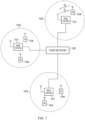
- Figure 1 provides a schematic diagram illustrating some basic functionality of a mobile telecommunications network / system operating in accordance with LTE principles and which may be adapted to implement embodiments of the disclosure as described further below.
- Various elements of Figure 1 and their respective modes of operation are well-known and defined in the relevant standards administered by the 3GPP (RTM) body, and also described in many books on the subject, for example, Holma H. and Toskala A [1]. It will be appreciated that operational aspects of the telecommunications network which are not specifically described below may be implemented in accordance with any known techniques, for example according to the relevant standards.
- the network 100 includes a plurality of base stations 101 connected to a core network 102.
- Each base station provides a coverage area 103 (i.e. a cell) within which data can be communicated to and from communications devices 104.
- Data is transmitted from base stations 101 to communications devices 104 within their respective coverage areas 103 via a radio downlink.
- Data is transmitted from communications devices 104 to the base stations 101 via a radio uplink.
- the uplink and downlink communications are made using radio resources that are licenced for exclusive use by the operator of the network 100.
- the core network 102 routes data to and from the communications devices 104 via the respective base stations 101 and provides functions such as authentication, mobility management, charging and so on.
- Communications devices may also be referred to as mobile stations, user equipment (UE), user device, mobile radio, and so forth.
- Base stations may also be referred to as transceiver stations / infrastructure equipment / NodeBs / eNodeBs (eNB for short), and so forth.
- Wireless communications systems such as those arranged in accordance with the 3GPP defined Long Term Evolution (LTE) architecture use an orthogonal frequency division modulation (OFDM) based interface for the radio downlink (so-called OFDMA) and a single carrier frequency division multiple access scheme (SC-FDMA) on the radio uplink.
- OFDM orthogonal frequency division modulation
- SC-FDMA single carrier frequency division multiple access scheme
- FIG. 2A An example configuration of a wireless communications network which uses some of the terminology proposed for NR and 5G is shown in Figure 2A .
- a plurality of transmission and reception points (TRPs) 210 are connected to distributed control units (DUs) 241, 242 by a connection interface represented as a line 216.
- DUs distributed control units
- Each of the TRPs 210 is arranged to transmit and receive signals via a wireless access interface within a radio frequency bandwidth available to the wireless communications network.
- DUs distributed control units
- each of the TRPs 210 forms a cell of the wireless communications network as represented by a dashed line 212.
- Each of the distributed control units 241, 242 are connected to a co-ordinating unit (CU) 240 via an interface.
- the co-ordinating unit 240 is then connected to the a core network 220 which may contain all other functions required to transmit data for communicating to and from the wireless communications devices and the core network 220 may be connected to other networks 230.
- the elements of the wireless access network shown in Figure 2A may operate in a similar way to corresponding elements of an LTE network as described with regard to the example of Figure 1 .
- operational aspects of the telecommunications network represented in Figure 2A and of other networks discussed herein in accordance with embodiments of the disclosure, which are not specifically described (for example in relation to specific communication protocols and physical channels for communicating between different elements) may be implemented in accordance with any known techniques, for example according to currently used approaches for implementing such operational aspects of wireless telecommunications systems, e.g. in accordance with the relevant standards.
- the TRPs 210 of Figure 2A may in part have a corresponding functionality to a base station or eNodeB of an LTE network.
- the communications devices 214 may have a functionality corresponding to UE devices known for operation with an LTE network.
- operational aspects of a new RAT network may be different to those known from LTE or other known mobile telecommunications standards.
- each of the core network component, base stations and terminal devices of a new RAT network will be functionally similar to, respectively, the core network component, base stations and terminal devices of an LTE wireless communications network.
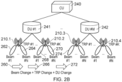
- Figure 2B provides a schematic representation of the wireless communications network shown in Figure 2A arranged to illustrate a scenario of communication with a UE 214 which is mobile.
- a UE 214 is transmitting from left to right and detecting the beams formed by the TRPs 210.1, 210.2 the UE 214 may be able to detect each of the beams in turn but not contemporaneously. Accordingly, the UE 214 should be arranged to hand over between different TRPs to transmit and/or receive signals represented as different beams as it travels from a left hand side of Figure 2B to the right hand side.
- a first arrow 260 as a UE 214 travels from an area where it can receive a first of the beams 262 to an area where it can receive a second of the beams 264, the UE 214 should hand over transmission and reception from the first beam 262 to the second beam 264.
- a second arrow 266 as the UE 214 travels further to detect a first beam 268 of a second TRP 210.2, then the UE 214 should hand over from the first TRP 201.1 to the second TRP 210.2.
- the UE 214 should hand over from a first of the distributed units 241 to a second the distributed units 242. More details of the handover arrangement are disclosed in [2].
- a RAN study item [3] provides justification and objectives with the development of NR systems, as described in the text taken from [3] below.
- 3GPP has to identify and develop the technology components needed for successfully standardizing the NR system timely satisfying both the urgent market needs, and the more long-term requirements set forth by the ITU-R IMT-2020 process. Further, the NR system should be able to use any spectrum band ranging at least up to 100 GHz that may be made available for wireless communications even in a more distant future.
- RAN#68 saw the first draft study item proposals for discussion for points 2) [RP-150781] and 3) [RP-150813], and further RAN#69 saw the first draft study item proposals for 4) in [RP-151278] and [RP-151551].
- the study aims to develop an NR access technology to meet a broad range of use cases including enhanced mobile broadband, massive MTC, critical MTC, and additional requirements defined during the RAN requirements study.
- the new RAT will consider frequency ranges up to 100 GHz [TR38.913].
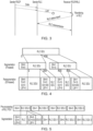
- FIG. 3 is taken from [7] and depicts retransmission in the RLC layer.
- RLC transmission could overcome the drawbacks of PDCP transmission in that no extra delay is incurred from the non-ideal link between sender PDCP and sender RLC during the retransmission process.
- Figure 4 is taken from [10], and illustrates an example of SO-based segmentation and resegmentation.
- the same size of segmented SDU with a previous LTE case (which is described in [10] with reference to Figure 1 of [10]) is assumed in the example.
- Figure 4 shows that it is possible for SO-based segmentation to perform the same level of segmentation of LTE. This means that segmentation and resegmentation can be unified by SO-based segmentation.
- FIG. 5 is also taken from [10], and illustrates an example of pre-processing of RLC PDUs and segmentation for SO-based segmentation.
- FI framing info
- the SO-based segmentation as shown in Figure 5 does not need to change sequence number of each pre-processed RLC PDU. Therefore, pre-processing of RLC PDUs for reducing real-time processing requires SO-based segmentation rather than FI-based segmentation.
- FIG. 6 shows an acknowledged mode (AM) RLC entity 601, comprising a transmission buffer 602, segmentation and concatenation means 603, RLC header addition means 604, retransmission buffer 605, RLC control means 606, routing means 607, a reception buffer 608 which may carry out re-ordering in accordance with a HARQ protocol, RLC removal means 609 and SDU reassembly means 610.
- AM acknowledged mode
- the transmitting side of an AM RLC entity supports retransmission of RLC data PDUs (ARQ). If the RLC data PDU to be retransmitted does not fit within the total size of RLC PDU(s) indicated by lower layer at the particular transmission opportunity notified by lower layer, the AM RLC entity can re-segment the RLC data PDU into AMD PDU segments and the number of re-segmentation is not limited.
- the transmitting side of an AM RLC entity forms AMD PDUs from RLC SDUs received from upper layer or AMD PDU segments from RLC data PDUs to be retransmitted, it shall include relevant RLC headers in the RLC data PDU.
- an AM RLC entity When the receiving side of an AM RLC entity receives RLC data PDUs, it shall detect whether or not the RLC data PDUs have been received in duplication, and discard duplicated RLC data PDUs, reorder the RLC data PDUs if they are received out of sequence, detect the loss of RLC data PDUs at lower layers and request retransmissions to its peer AM RLC entity and reassemble RLC SDUs from the reordered RLC data PDUs and deliver the RLC SDUs to upper layer in sequence.
- the receiving side of an AM RLC entity shall if possible, reassemble RLC SDUs from the RLC data PDUs that are received out of sequence and deliver them to upper layer, discard any remaining RLC data PDUs that could not be reassembled into RLC SDUs and initialise relevant state variables and stop relevant timers.
- Protocol architecture of a UE 104 comprises, at layer 2 of the protocol stack, a PDCP layer 701, an RLC layer 702 and a MAC layer 703, all above the physical layer 704 at layer 1 of the protocol stack.
- protocol architecture of an eNodeB 101 comprises, at layer 2 of the protocol stack, a PDCP layer 711, an RLC layer 712 and a MAC layer 713, all above the physical layer 714 at layer 1 of the protocol stack.
- Data is able to be communicated between the PDCP layer 701 of the UE 104 and the PDCP layer 711 of the eNodeB 101, between the RLC layer 702 of the UE 104 and the RLC layer 712 of the eNodeB 101, between the MAC layer 703 of the UE 104 and the MAC layer 713 of the eNodeB 101 and between the physical layer 704 of the UE 104 and the physical layer 714 of the eNodeB 101.
- RLC polling is specified as follows (from [11]).
- An AM RLC entity can poll its peer AM RLC entity in order to trigger STATUS reporting at the peer AM RLC entity.
- the transmitting side of an AM RLC entity Upon assembly of a new AMD PDU, the transmitting side of an AM RLC entity shall:
- the transmitting side of an AM RLC entity shall:
- the transmitting side of an AM RLC entity shall:
- the transmitting side of an AM RLC entity shall:
- the UE RLC entity maintains 2 counters.
- One counter counts transmitted RLC PDUs, and the other counts transmitted bytes. If either count reaches the configured threshold, a poll is sent (requesting ACK/NACK in a status report) and the counters are reset.
- the UE does not receive a response to the poll within the t-PollRetransmit then the PDU containing the poll is resent (Assumed to be not received).
- the main purpose of the polling mechanism is to advance the transmission window, which avoids protocol stalling. Errors are typically corrected at HARQ, with any leftover errors detected by the receiving RLC entity using the reordering timer.
- the polling mechanism confirms the last acknowledged sequence number so that the window can be advanced so to accept new data from upper layers.
- the reason for maintaining 2 counters is to account for variable PDU size. In case of good radio conditions, the PDU size is large and so memory would be the limitation (UE can reserve a fixed amount of memory to store/buffer data). In case of poor radio conditions, the PDU size is small, so the RLC sequence number is the limitation. If the poll is sent after more than half of the SN range, then there is a risk of protocol stalling.
- polling is based on the sequence number rather than the number of PDUs which have been transmitted.
- PDCP sequence numbers could be used for performing RLC ARQ.
- the PDCP sequence numbers could be used for setting the poll bit (which may be managed by either RLC or PDCP), nor that the sequence numbers themselves could be used as a basis for the receiver of the PDUs to trigger a status report message to the transmitter.
- Figure 8 is a part schematic representation, part message flow diagram of communications between a transmitting node 810 and a receiving node 820 of a mobile communications system 800 in accordance with embodiments of the present technique.
- the transmitting node 810 comprises transmitter circuitry 811 configured to transmit 840 signals representing protocol data units formed from one or more service data units via a wireless access interface 830 of the mobile communications system 800 to the receiving node 820 of the mobile communications system 800 according to an automatic repeat request process, receiver circuitry 812 configured to receive signals from the receiving node 820 via the wireless access interface 830, controller circuitry 813 configured to control the transmitter circuitry 811 to transmit the signals and to control the receiver circuitry 812 to receive the signals, and a buffer 814 configured to store data conveyed by or representing the protocol data units for transmission to the receiving node 820 according to the automatic repeat request process.
- Each of the protocol data units as can be seen in Figure 8 , has a sequence number defining its position in a predetermined order.
- the receiving node 820 comprises receiver circuitry 822 configured to receive 840 the signals representing protocol data units formed from one or more service data units via the wireless access interface 830 of the mobile communications system 800 from the transmitting node 810 of the mobile communications system 800 according to the automatic repeat request process, transmitter circuitry 821 configured to transmit signals to the transmitting node 810 via the wireless access interface 830, and controller circuitry 823 configured to control the transmitter circuitry 821 to transmit the signals and to control the receiver circuitry 822 to receive the signals.
- receiver circuitry 822 configured to receive 840 the signals representing protocol data units formed from one or more service data units via the wireless access interface 830 of the mobile communications system 800 from the transmitting node 810 of the mobile communications system 800 according to the automatic repeat request process
- transmitter circuitry 821 configured to transmit signals to the transmitting node 810 via the wireless access interface 830
- controller circuitry 823 configured to control the transmitter circuitry 821 to transmit the signals and to control the receiver circuitry 822 to receive the signals.
- the controller circuitry 813 of the transmitting node 810 is configured in combination with the transmitter circuitry 811 and the buffer 814 of the transmitting node 810 to detect 850, based on the sequence number of one or more of the protocol data units, whether predetermined criteria are satisfied, and in response, to transmit 851 a polling bit to the receiving node 820 in the one or more of the protocol data units for which the sequence number satisfies the predetermined criteria.
- the controller circuitry 813 may then be configured in combination with the transmitter circuitry 811, the receiver circuitry 812 and the buffer 814 to receive 860, from the receiving node 820, in response to the polling bit, a status report message comprising a negative acknowledgement for one or more protocol data units which were not successfully received by the receiving node 820, and to re-transmit to the receiving node 820 the one or more protocol data units which were not successfully received by the receiving node 820.
- the controller circuitry 823 of the receiving node 820 is configured in combination with the receiver 822 of the receiving node 820 to detect 855, based on the sequence number of one or more of the protocol data units, whether predetermined criteria are satisfied, and in response to transmit 860 a status report message comprising a negative acknowledgement for one or more protocol data units which were not successfully received.
- the status report message may be transmitted 860 on the basis of the detection 855 of the sequence numbers alone or alternatively in response to the reception 851 of a polling bit from the transmitting node 810.
- the receiving node 820 may then, in some embodiments of the present technique, be configured to receive from the transmitting node 810 as a re-transmission, in response to the status report message, the one or more protocol data units which were not successfully received from the transmitting node 810.
- the buffer 814 comprises a sliding window which represents protocol data units which have been transmitted by the transmitting node 810 but not yet successfully acknowledged by the receiving node 820, an upper edge of the sliding window being set to a first value equal to a sequence number to be assigned for a next newly generated protocol data unit at the transmitting node 810 and a lower edge of the sliding window being set to a second value equal to a sequence number of a next protocol data unit for which a successful acknowledgement is to be received from the receiving node 820 in the predetermined order
- the controller circuitry 813 is configured in combination with the transmitter circuitry 811, the receiver circuitry 812 and the buffer 813 to receive from the receiving node an indication that one or more of the protocol data units have not been successfully received by the receiving node 820, to re-transmit from the buffer 814 the one or more of the protocol data units which have not been successfully received by the receiving node 820, and to advance the sliding window according to the second value, such that memory of the buffer 8
- the PDUs up to a particular sequence number for example PDUs up to and including the PDU containing the polling bit, or the PDUs up to and including the PDU with a sequence number satisfying the predetermined criteria.
- a number of PDUs up to any other PDU up to the PDU containing the poll bit or satisfying the predetermined criteria may all be successfully received.
- the sliding window of the buffer can be advanced to free the memory of the buffer at locations at which are stored each of those PDUs which were successfully received in sequence number order, as no re-transmissions for any of those PDUs are therefore required.
- the buffer comprises a sliding window which represents protocol data units which have been transmitted by the transmitting node but not yet successfully acknowledged by the receiving node, an upper edge of the sliding window being set to a first value equal to a sequence number to be assigned for a next newly generated protocol data unit at the transmitting node and a lower edge of the sliding window being set to a second value equal to a sequence number of a next protocol data unit for which a successful acknowledgement is to be received from the receiving node in the predetermined order
- the controller circuitry is configured in combination with the transmitter circuitry, the receiver circuitry and the buffer to receive from the receiving node an indication that all of the protocol data units up to and including the protocol data unit having a sequence number equal to the second value, and to advance the sliding window according to the second value, such that memory of the buffer is freed at locations at which are stored each of the protocol data units in the predetermined order which have been successfully received before the one or more protocol data units which have not been successfully received.
- the main advantage of using a fixed SN is that it is no longer necessary to maintain any counters, which involve some processing overhead to manage.
- the RLC headers can be hard-coded with a poll bit in certain SNs.
- the protocol data units each include a header which is at least partly pre-generated to include the sequence number of the each of the protocol data units.
- the predetermined criteria comprises the sequence number of the one or more of the protocol data units being equal to one of one or more predetermined values of sequence numbers, the one or more predetermined values of sequence numbers being known by the transmitting device and the receiving device, or wherein the predetermined criteria comprises the sequence number of the one or more of the protocol data units being equal to one of one or more values of sequence numbers configured by the mobile communications system and provided to the transmitting node and the receiving node.
- the predetermined criteria comprises the sequence number of the one or more of the protocol data units being greater than or equal to one of one or more predetermined values of sequence numbers, the one or more predetermined values of sequence numbers being known by the transmitting device and the receiving device, or wherein the predetermined criteria comprises the sequence number of the one or more of the protocol data units being greater than or equal one of one or more values of sequence numbers configured by the mobile communications system and provided to the transmitting node and the receiving node -
- these embodiments include those in which polling bits are not used, or a polling bit is not successfully received by the receiving node, which then triggers the sending of a status report message when a higher SN than expected is received.
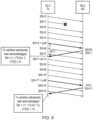
- FIG. 9 An example of basic polling operation and transmitter window state variables in accordance with the present technique is shown in Figure 9 .
- the fixed SN is always known to both the transmitter and the receiver. Due to this, the receiver can proactively send a status report if it receives any PDU with a higher sequence number than the fixed polling SN. This is particularly useful in case the PDU containing a poll bit is received out of order, or has been lost on the radio link and needs to be retransmitted. It allows the receiver to trigger a status report more quickly, and so any PDUs for which a NACK is transmitted by the receiving node can be retransmitted more quickly by the transmitting node, improving the overall performance as well as the processing benefit at the transmitter.
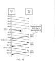
- Figure 10 shows an example of transmitting negative acknowledgements (NACKs) by the receiving device automatically based on the sequence number in accordance with embodiments of the present technique.
- NACKs negative acknowledgements
- the receiver detects SN > N
- a status report is automatically generated. This allows recovery of the error and advancing the window more quickly.
- the drawback of this approach is a slightly increased overhead due to the additional STATUS report - therefore it's possible such behaviour is configurable, so that the network can choose the operation it prefers (faster error recovery, or less overhead).
- Another alternative is to remove the poll bit in case of retransmission.
- a poll bit should be included when the buffer becomes empty, in order to trigger a status report for acknowledgement of all of the data.
- the final PDU might alternatively be a re-transmission.
- the transmitting node is configured to detect that the next of the protocol data units to be transmitted is the last protocol data unit in the buffer, and to transmit a polling bit to the receiving node along with the next of the protocol data units to be transmitted.
- the transmitting node is configured to detect that the number of protocol units or the number of bytes stored in the buffer exceeds a predetermined threshold, and in response to transmit a polling bit to the receiving node along with the next of the protocol data units to be transmitted.
- the receiver can trigger a status report in case it detects an error.
- the LTE mechanism uses a reordering timer, however it might also be considered that a status report can be triggered in case a missing RLC SN is detected, at current SN - N.
- the receiving node is configured to detect that a received protocol data unit has a sequence number which is received out of an expected order corresponding to the order of the sequence numbers, and in response to transmit to the transmitting node a status report comprising a negative acknowledgement for a protocol data units having the expected sequence number to match the predetermined criteria, and to receive from the transmitting node as a re-transmission a polling bit and the protocol data unit having the expected number to match the predetermined criteria.
- receiving a small number of PDUs out of order is tolerated by the receiving node, to compensate for HARQ retransmissions of PDUs which were not successfully received during their first transmissions.
- a gap in reception of PDUs may be detected by the receiving node, which would receive nothing at a time when it would be expecting to receive a PDU with a particular SN.
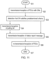
- FIG 11 shows a flow diagram illustrating a method of communications between a transmitting node and a receiving node of a mobile communications system in accordance with embodiments of the present technique.
- the process begins in step S1.
- the method comprises, in step S2, the transmission of by the transmitting node and reception of by the receiving node signals representing protocol data units formed from one or more service units via a wireless access interface of the mobile communications system according to an automatic repeat request process, wherein each of the protocol data units has a sequence number defining their position in a predetermined order - these protocol data units are stored in a buffer at the transmitting node once they have been transmitted to the receiving node.
- the method then comprises in step S3, detecting, based on the sequence number of one or more of the protocol data units, the predetermined criteria are satisfied.
- the process advances to step S4, which comprises the transmission of by the transmitting node and reception of by the receiving node a polling bit.
- the method comprises the transmission of by the receiving node and reception of by the transmitting node a status report message comprising a negative acknowledgement for one or more protocol data units which were not successfully received by the receiving node.
- step S6 comprises the re-transmitting of by the transmitting node and reception of by the receiving node the PDUs for which the negative acknowledgements were transmitted by the receiving node in the status report message.
- step S7 comprises the re-transmitting of by the transmitting node and reception of by the receiving node the PDUs for which the negative acknowledgements were transmitted by the receiving node in the status report message.
- the receiving node forms part of a mobile communications network and may, for example, be an infrastructure equipment (base station/eNodeB etc.)
- the transmitting node may, for example, be a communications device, or user equipment (UE).
- the transmitter circuitry 811, 821 may include analogue and digital circuitry such as radio frequency circuits and filters, analogue amplifiers as well as digital signalling processing software implemented as application specific semiconductor circuits, dedicated signalling processing logic and other processors.
- the receiver circuitry 812, 822 may include radio frequency circuitry and filters, signal processing software in the form of digital signal processors and other devices for detecting signals.
- the controller circuitry 813, 823 may be formed from processors executing software, application specific semiconductor circuits or hardware circuits comprising digital logic.
- the controller circuitry 823 of the receiving node 820 can include a so-called "scheduler" which schedules the transmission of signals and the reception of signals via the wireless access interface.
- embodiments of the present technique include the simplification of RLC polling. Pre-configuration of RLC headers is enabled, which reduces processing overheads especially at a high data throughput. Furthermore, embodiments of the present technique allow the receiver to automatically respond without re-transmission of PDUs containing poll bits, allowing for faster re-transmission and improved overall performance.
- Described embodiments may be implemented in any suitable form including hardware, software, firmware or any combination of these. Described embodiments may optionally be implemented at least partly as computer software running on one or more data processors and/or digital signal processors.
- the elements and components of any embodiment may be physically, functionally and logically implemented in any suitable way. Indeed the functionality may be implemented in a single unit, in a plurality of units or as part of other functional units. As such, the disclosed embodiments may be implemented in a single unit or may be physically and functionally distributed between different units, circuitry and/or processors.
Landscapes
- Engineering & Computer Science (AREA)
- Computer Networks & Wireless Communication (AREA)
- Signal Processing (AREA)
- Mobile Radio Communication Systems (AREA)
Claims (13)
- Noeud de transmission (810) fonctionnant avec un système de communication mobile (800) comprenantune circuiterie d'émetteurs (811) configurée pour transmettre (840) des signaux représentant des unités de données de protocole formées à partir d'une ou plusieurs unités de données de service par l'intermédiaire d'une interface d'accès sans fil (830) du système de communication mobile à un noeud de réception (820) du système de communication mobile selon un processus de demande de répétition automatique,une circuiterie de récepteurs (812) configurée pour recevoir des signaux en provenance du noeud de réception par l'intermédiaire de l'interface d'accès sans fil,une circuiterie de dispositifs de commande (813) configurée pour commander la circuiterie d'émetteurs afin de transmettre les signaux et commander la circuiterie de récepteurs afin de recevoir les signaux, etune mémoire tampon (814) configurée pour stocker des données véhiculées par les unités de données de protocole ou représentant celles-ci, en vue de leur transmission au noeud de réception selon le processus de demande de répétition automatique,dans lequel chaque unité de données de protocole a un numéro de séquence définissant sa position dans un ordre prédéterminé, et la circuiterie de dispositifs de commande est configurée en combinaison avec la circuiterie d'émetteurs et la mémoire tamponpour détecter (850), sur la base du numéro de séquence d'une ou de plusieurs parmi les unités de données de protocole, si des critères prédéterminés sont satisfaits, dans lequel les critères prédéterminés comprennent le numéro de séquence de la ou des unités de données de protocole égal à une valeur fixe parmi une ou plusieurs valeurs de numéros de séquence pouvant être configurées par le réseau et fournies au noeud de transmission et au noeud de réception, et en réponsepour transmettre (851) un bit d'interrogation au noeud récepteur dans la ou des unités de données de protocole pour lesquelles le numéro de séquence satisfait les critères prédéterminés.
- Noeud de transmission selon la revendication 1, dans lequel les unités de données de protocole satisfaisant les critères prédéterminés comprennent chacune un en-tête qui est au moins partiellement pré-généré pour inclure le numéro de séquence de chacune des unités de données de protocole.
- Noeud de transmission selon la revendication 1, dans lequel la mémoire tampon comprend une fenêtre coulissante qui représente des unités de données de protocole qui ont été transmises par le noeud de transmission mais qui n'ont pas encore fait l'objet d'un accusé de réception avec succès par le noeud de réception, un bord supérieur de la fenêtre coulissante est défini à une première valeur égale à un numéro de séquence à attribuer à une prochaine unité de données de protocole nouvellement générée au niveau du noeud de transmission et un bord inférieur de la fenêtre coulissante est défini à une seconde valeur égale à un numéro de séquence d'une prochaine unité de données de protocole pour laquelle un accusé de réception réussi doit être reçu en provenance du noeud de réception dans l'ordre prédéterminé, et la circuiterie de dispositifs de commande est configurée en combinaison avec la circuiterie d'émetteurs, la circuiterie de récepteurs et la mémoire tamponpour recevoir en provenance du noeud récepteur une indication selon laquelle une ou plusieurs parmi les unités de données de protocole n'ont pas été reçues avec succès par le noeud récepteur,pour retransmettre à partir de la mémoire tampon la ou les unités de données de protocole qui n'ont pas été reçues avec succès par le noeud récepteur, etpour avancer la fenêtre coulissante selon la seconde valeur, de telle sorte que la mémoire tampon est libérée aux endroits où sont stockées chacune des unités de données de protocole dans l'ordre prédéterminé qui ont été reçues avec succès avant la ou les unités de données de protocole qui n'ont pas été reçues avec succès.
- Noeud de transmission selon la revendication 1, dans lequel la mémoire tampon comprend une fenêtre coulissante qui représente des unités de données de protocole qui ont été transmises par le noeud de transmission mais qui n'ont pas encore fait l'objet d'un accusé de réception avec succès par le noeud de réception, un bord supérieur de la fenêtre coulissante est défini à une première valeur égale à un numéro de séquence à attribuer à une prochaine unité de données de protocole nouvellement générée au niveau du noeud de transmission et un bord inférieur de la fenêtre coulissante est défini à une seconde valeur égale à un numéro de séquence d'une prochaine unité de données de protocole pour laquelle un accusé de réception réussi doit être reçu en provenance du noeud de réception dans l'ordre prédéterminé, et la circuiterie de dispositifs de commande est configurée en combinaison avec la circuiterie d'émetteurs, la circuiterie de récepteurs et la mémoire tamponpour recevoir en provenance du noeud de réception une indication selon laquelle toutes les unités de données de protocole, jusqu'à et y compris l'unité de données de protocole ayant un numéro de séquence égal à la seconde valeur, etpour avancer la fenêtre coulissante selon la seconde valeur, de telle sorte que la mémoire tampon est libérée aux endroits où sont stockées chacune des unités de données de protocole dans l'ordre prédéterminé qui ont été reçues avec succès avant la ou les unités de données de protocole qui n'ont pas été reçues avec succès.
- Noeud de transmission selon la revendication 1, dans lequel la circuiterie de dispositifs de commande est configurée en combinaison avec la circuiterie d'émetteurs, la circuiterie de récepteurs et la mémoire tamponpour recevoir en provenance du noeud récepteur, en réponse au bit d'interrogation, un rapport d'état comprenant un accusé de réception négatif pour une ou plusieurs unités de données de protocole qui n'ont pas été reçues avec succès par le noeud récepteur, etpour retransmettre au noeud récepteur la ou les unités de données de protocole qui n'ont pas été reçues avec succès par le noeud récepteur.
- Noeud de transmission selon la revendication 1, dans lequel la circuiterie de dispositifs de commande est configurée en combinaison avec la circuiterie d'émetteurs et la mémoire tamponpour détecter que la prochaine unité de données de protocole à transmettre est la dernière unité de données de protocole transmise à partir de la mémoire tampon, etpour transmettre un bit d'interrogation au noeud récepteur en même temps que la prochaine unité de données de protocole à transmettre.
- Noeud de transmission selon la revendication 1, dans lequel la circuiterie de dispositifs de commande est configurée en combinaison avec la circuiterie d'émetteurs et la mémoire tamponpour détecter que le nombre d'unités de données de protocole ou le nombre d'octets stockés dans la mémoire tampon dépasse un seuil prédéterminé, et en réponsepour transmettre un bit d'interrogation au noeud récepteur en même temps que la prochaine unité de données de protocole à transmettre.
- Noeud de réception (820) fonctionnant avec un système de communication mobile (800) comprenantune circuiterie de récepteurs (822) configurée pour recevoir (840) des signaux représentant des unités de données de protocole formées à partir d'une ou plusieurs unités de données de service par l'intermédiaire d'une interface d'accès sans fil (830) du système de communication mobile en provenance d'un noeud de transmission (810) du système de communication mobile selon un processus de demande de répétition automatique,une circuiterie d'émetteurs (821) configurée pour transmettre des signaux au noeud de transmission par l'intermédiaire de l'interface d'accès sans fil, etla circuiterie de dispositifs de commande (823) configurée pour commander la circuiterie d'émetteurs afin de transmettre les signaux et commander la circuiterie de récepteurs afin de recevoir les signaux,dans lequel chaque unité de données de protocole a un numéro de séquence définissant sa position dans un ordre prédéterminé, et dans lequel la circuiterie de dispositifs de commande est configurée en combinaison avec la circuiterie de récepteurspour détecter (855), sur la base du numéro de séquence d'une ou de plusieurs parmi les unités de données de protocole, qu'une unité de données de protocole satisfaisant des critères prédéterminés et transportant un bit d'interrogation est perdue, dans lequel le critère prédéterminé comprend le numéro de séquence de l'unité de données de protocole égal à une valeur fixe parmi une ou plusieurs valeurs de numéros de séquence pouvant être configurées par le réseau et fournies au noeud de transmission et au noeud de réception, et en réponsepour transmettre (860) un message de rapport d'état comprenant un accusé de réception négatif pour une ou plusieurs unités de données de protocole qui n'ont pas été reçues avec succès.
- Procédé de commande de communication au niveau d'un noeud de transmission (810) fonctionnant avec un système de communication mobile (800), le procédé comprenantla transmission (S2) de signaux représentant des unités de données de protocole formées à partir d'une ou plusieurs unités de service par l'intermédiaire d'une interface d'accès sans fil (830) du système de communication mobile à un noeud de réception (820) du système de communication mobile selon un processus de demande de répétition automatique, dans lequel chacune des unités de données de protocole a un numéro de séquence définissant sa position dans un ordre prédéterminé,le stockage dans une mémoire tampon (814) des données véhiculées par ou représentant les unités de données de protocole transmises au noeud de réception selon le processus de demande de répétition,la détection (S3), sur la base du numéro de séquence d'une ou de plusieurs parmi les unités de données de protocole, du fait de savoir si des critères prédéterminés sont satisfaits, dans lequel les critères prédéterminés comprennent le numéro de séquence d'une ou de plusieurs parmi les unités de données de protocole égal à une valeur fixe parmi une ou plusieurs valeurs de numéros de séquence pouvant être configurés par le réseau et fournies au noeud de transmission et au noeud de réception, et en réponsela transmission (S4) d'un bit d'interrogation au noeud récepteur dans la ou les unités de données de protocole pour lesquelles le numéro de séquence satisfait les critères prédéterminés.
- Procédé de commande de communication au niveau d'un noeud de réception (820) fonctionnant avec un système de communication mobile (800), le procédé comprenantla réception (S1) de signaux représentant des unités de données de protocole formées à partir d'une ou plusieurs unités de données de service par l'intermédiaire d'une interface d'accès sans fil (830) du système de communication mobile en provenance d'un noeud de transmission (810) du système de communication mobile selon un processus de demande de répétition automatique, dans lequel chacune des unités de données de protocole a un numéro de séquence définissant sa position dans un ordre prédéterminé,la détection (S3), sur la base du numéro de séquence d'une ou plusieurs parmi les unités de données de protocole, du fait qu'une unité de données de protocole satisfaisant des critères prédéterminés et transportant un bit d'interrogation est perdue, dans lequel le critère prédéterminé comprend le numéro de séquence de l'unité de données de protocole égal à une valeur fixe parmi une ou plusieurs valeurs de numéros de séquence pouvant être configurées par le réseau et fournies au noeud de transmission et au noeud de réception, et en réponsela transmission (S5) d'un message de rapport d'état comprenant un accusé de réception négatif pour une ou plusieurs unités de données de protocole qui n'ont pas été reçues avec succès.
- Circuiterie pour un noeud de transmission (810) fonctionnant avec un système de communication mobiles (800) comprenantune circuiterie d'émetteurs (811) configurée pour transmettre (840) des signaux représentant des unités de données de protocole formées à partir d'une ou plusieurs unités de données de service par l'intermédiaire d'une interface d'accès sans fil (830) du système de communication mobile à un noeud de réception (820) du système de communication mobile selon un processus de demande de répétition automatique,une circuiterie de récepteurs (812) configurée pour recevoir des signaux en provenance du noeud de réception par l'intermédiaire de l'interface d'accès sans fil,une circuiterie de dispositifs de commande (813) configurée pour commander la circuiterie d'émetteurs afin de transmettre les signaux et commander la circuiterie de récepteurs afin de recevoir les signaux, etune mémoire tampon (814) configurée pour stocker des données véhiculées par les unités de données de protocole ou représentant celles-ci, en vue de leur transmission au noeud de réception selon le processus de demande de répétition automatique,dans lequel chaque unité de données de protocole a un numéro de séquence définissant sa position dans un ordre prédéterminé, et dans lequel la circuiterie de dispositifs de commande est configurée en combinaison avec la circuiterie d'émetteurs et la mémoire tamponpour détecter (850), sur la base du numéro de séquence d'une ou de plusieurs parmi les unités de données de protocole, si des critères prédéterminés sont satisfaits, dans lequel les critères prédéterminés comprennent le numéro de séquence de la ou des unités de données de protocole égal à une valeur fixe parmi une ou plusieurs valeurs de numéros de séquence pouvant être configurées par le réseau et fournies au noeud de transmission et au noeud de réception, et en réponsepour transmettre (851) un bit d'interrogation au noeud récepteur dans la ou des unités de données de protocole pour lesquelles le numéro de séquence satisfait les critères prédéterminés.
- Circuiterie pour un noeud de réception (820) fonctionnant avec un système de communication mobile (800) comprenantune circuiterie de récepteurs (822) configurée pour recevoir (840) des signaux représentant des unités de données de protocole formées à partir d'une ou plusieurs unités de données de service par l'intermédiaire d'une interface d'accès sans fil (830) du système de communication mobile en provenance d'un noeud de transmission (810) du système de communication mobile selon un processus de demande de répétition automatique,une circuiterie d'émetteurs (821) configurée pour transmettre des signaux au noeud de transmission par l'intermédiaire de l'interface d'accès sans fil, etla circuiterie de dispositifs de commande (823) configurée pour commander la circuiterie d'émetteurs afin de transmettre les signaux et commander la circuiterie de récepteurs afin de recevoir les signaux,dans lequel chaque unité de données de protocole a un numéro de séquence définissant sa position dans un ordre prédéterminé, et dans lequel la circuiterie de dispositifs de commande est configurée en combinaison avec la circuiterie de récepteurspour détecter (855), sur la base du numéro de séquence d'une ou de plusieurs parmi les unités de données de protocole, qu'une unité de données de protocole satisfaisant des critères prédéterminés et transportant un bit d'interrogation est perdue, dans lequel le critère prédéterminé comprend le numéro de séquence de l'unité de données de protocole égal à une valeur fixe parmi une ou plusieurs valeurs de numéros de séquence pouvant être configurées par le réseau et fournies au noeud de transmission et au noeud de réception, et en réponsepour transmettre (860) un message de rapport d'état comprenant un accusé de réception négatif pour une ou plusieurs unités de données de protocole qui n'ont pas été reçues avec succès.
- Système de communication mobile (800) comprenant un noeud de transmission (810) selon la revendication 1 et un noeud de réception (820) selon la revendication 8.
Applications Claiming Priority (2)
| Application Number | Priority Date | Filing Date | Title |
|---|---|---|---|
| EP16198536 | 2016-11-11 | ||
| PCT/EP2017/077922 WO2018086969A1 (fr) | 2016-11-11 | 2017-10-31 | Nœud de transmission, nœud de réception, procédés et système de communication mobile |
Publications (2)
| Publication Number | Publication Date |
|---|---|
| EP3523906A1 EP3523906A1 (fr) | 2019-08-14 |
| EP3523906B1 true EP3523906B1 (fr) | 2024-09-04 |
Family
ID=57354119
Family Applications (1)
| Application Number | Title | Priority Date | Filing Date |
|---|---|---|---|
| EP17791420.7A Active EP3523906B1 (fr) | 2016-11-11 | 2017-10-31 | Noeud de transmission, noeud de réception, procédés et système de communication mobile |
Country Status (3)
| Country | Link |
|---|---|
| US (2) | US10924219B2 (fr) |
| EP (1) | EP3523906B1 (fr) |
| WO (1) | WO2018086969A1 (fr) |
Families Citing this family (14)
| Publication number | Priority date | Publication date | Assignee | Title |
|---|---|---|---|---|
| CN109905206A (zh) * | 2017-12-07 | 2019-06-18 | 夏普株式会社 | 无线通信方法和设备 |
| KR20190097963A (ko) * | 2018-02-13 | 2019-08-21 | 한국전자통신연구원 | 무선 통신 시스템에서 데이터 송수신 방법 및 장치 |
| WO2019160469A1 (fr) | 2018-02-14 | 2019-08-22 | Telefonaktiebolaget Lm Ericsson (Publ) | Dispositif de transmission et procédé mis en œuvre en son sein permettant de gérer une communication |
| EP3570477B1 (fr) * | 2018-03-23 | 2021-09-01 | Guangdong Oppo Mobile Telecommunications Corp., Ltd. | Procédé et appareil de traitement de retransmission |
| DE112019002381T5 (de) * | 2018-05-10 | 2021-03-04 | Sony Corporation | Kommunikationsvorrichtung, kommunikationsverfahren und kommunikationsprogramm |
| US10849160B2 (en) * | 2019-02-26 | 2020-11-24 | Nokia Technologies Oy | Reinstating poll retransmission timer |
| US11153038B2 (en) * | 2019-11-22 | 2021-10-19 | Qualcomm Incorporated | MIC recovery of BR/EDR links |
| US11405324B1 (en) * | 2019-12-12 | 2022-08-02 | Amazon Technologies, Inc. | Packet serial number validation |
| US11870583B2 (en) * | 2020-01-31 | 2024-01-09 | Qualcomm Incorporated | Techniques for POLL bit trigger enhancement in a wireless communication system |
| US11871274B2 (en) * | 2020-05-04 | 2024-01-09 | Intel Corporation | Performance measurements and KPIs related to packet delay in NG-RAN and 5GS |
| US20230308221A1 (en) * | 2020-08-03 | 2023-09-28 | Qualcomm Incorporated | Mrb architecture with pdcp retransmission |
| CN114339614B (zh) * | 2020-09-29 | 2023-07-28 | 上海朗帛通信技术有限公司 | 一种被用于无线通信的方法和设备 |
| CN113726482B (zh) * | 2021-08-27 | 2023-09-05 | 哲库科技(北京)有限公司 | 一种数据重传方法、装置及存储介质 |
| CN117176809B (zh) * | 2023-09-01 | 2024-08-02 | 中科驭数(北京)科技有限公司 | 一种数据交互方法及系统 |
Family Cites Families (5)
| Publication number | Priority date | Publication date | Assignee | Title |
|---|---|---|---|---|
| KR100765121B1 (ko) * | 2001-11-24 | 2007-10-11 | 엘지전자 주식회사 | 송신버퍼의 프로토콜 데이터 유닛 폴링 방법 |
| EP1424815B1 (fr) * | 2002-11-26 | 2007-02-07 | Innovative Sonic Limited | Méthode d'interrogation des rapports d'états avec accusé de reception |
| GB2425923A (en) * | 2005-05-04 | 2006-11-08 | Nec Technologies | Incorporating count values into protocol data units to facilitate detection of lost PDU's |
| US8687495B2 (en) * | 2007-03-16 | 2014-04-01 | Qualcomm Incorporated | Method and apparatus for polling in a wireless communication system |
| PL3700114T3 (pl) * | 2008-01-08 | 2022-04-04 | Unwired Planet International Limited | Sposób i układ w bezprzewodowej sieci komunikacyjnej |
-
2017
- 2017-10-31 WO PCT/EP2017/077922 patent/WO2018086969A1/fr not_active Ceased
- 2017-10-31 EP EP17791420.7A patent/EP3523906B1/fr active Active
- 2017-10-31 US US16/346,543 patent/US10924219B2/en active Active
-
2021
- 2021-02-15 US US17/176,137 patent/US11646825B2/en active Active
Also Published As
| Publication number | Publication date |
|---|---|
| EP3523906A1 (fr) | 2019-08-14 |
| US11646825B2 (en) | 2023-05-09 |
| US20210167896A1 (en) | 2021-06-03 |
| WO2018086969A1 (fr) | 2018-05-17 |
| US20200059324A1 (en) | 2020-02-20 |
| US10924219B2 (en) | 2021-02-16 |
Similar Documents
| Publication | Publication Date | Title |
|---|---|---|
| US11646825B2 (en) | Transmitting node, receiving node, methods and mobile communications system | |
| US11831558B2 (en) | Efficient discard mechanism in small cell deployment | |
| US11202279B2 (en) | Method and apparatus for processing data in wireless communication system | |
| US11184801B2 (en) | Method and device for transmitting data unit | |
| JP5671122B2 (ja) | 無線通信システムの状態情報送信方法及び受信装置 | |
| US8413002B2 (en) | Method of performing ARQ procedure for transmitting high rate data | |
| KR101211758B1 (ko) | 무선 통신 시스템의 블록 데이터 생성 방법 | |
| US10819416B2 (en) | Apparatuses and methods for using ARQ processes in a relay device | |
| US20200045766A1 (en) | Wireless node communication method and apparatus in wireless communication system | |
| KR101635433B1 (ko) | 재전송 요청을 위한 제어 메시지를 처리하는 방법 및 장치 | |
| ZA200405986B (en) | Method for moving a receive window in a radio access network | |
| US11240703B2 (en) | Communications devices, method and mobile communications system | |
| US8345649B2 (en) | Method for indication of consecutive data units in a RAN | |
| EP3824663B1 (fr) | Procédé et appareil de communication de noeud sans fil dans un système de communications sans fil | |
| CN116261848A (zh) | 用于新无线电的无线电链路控制累积模式 | |
| KR20120023374A (ko) | 무선링크제어계층에서의 데이터 전송 장치 및 방법 |
Legal Events
| Date | Code | Title | Description |
|---|---|---|---|
| STAA | Information on the status of an ep patent application or granted ep patent |
Free format text: STATUS: UNKNOWN |
|
| STAA | Information on the status of an ep patent application or granted ep patent |
Free format text: STATUS: THE INTERNATIONAL PUBLICATION HAS BEEN MADE |
|
| PUAI | Public reference made under article 153(3) epc to a published international application that has entered the european phase |
Free format text: ORIGINAL CODE: 0009012 |
|
| STAA | Information on the status of an ep patent application or granted ep patent |
Free format text: STATUS: REQUEST FOR EXAMINATION WAS MADE |
|
| 17P | Request for examination filed |
Effective date: 20190511 |
|
| AK | Designated contracting states |
Kind code of ref document: A1 Designated state(s): AL AT BE BG CH CY CZ DE DK EE ES FI FR GB GR HR HU IE IS IT LI LT LU LV MC MK MT NL NO PL PT RO RS SE SI SK SM TR |
|
| AX | Request for extension of the european patent |
Extension state: BA ME |
|
| DAV | Request for validation of the european patent (deleted) | ||
| DAX | Request for extension of the european patent (deleted) | ||
| STAA | Information on the status of an ep patent application or granted ep patent |
Free format text: STATUS: EXAMINATION IS IN PROGRESS |
|
| 17Q | First examination report despatched |
Effective date: 20200721 |
|
| RAP3 | Party data changed (applicant data changed or rights of an application transferred) |
Owner name: SONY GROUP CORPORATION Owner name: SONY EUROPE LIMITED |
|
| GRAP | Despatch of communication of intention to grant a patent |
Free format text: ORIGINAL CODE: EPIDOSNIGR1 |
|
| STAA | Information on the status of an ep patent application or granted ep patent |
Free format text: STATUS: GRANT OF PATENT IS INTENDED |
|
| RIC1 | Information provided on ipc code assigned before grant |
Ipc: H04L 1/1867 20230101ALI20240313BHEP Ipc: H04L 1/1607 20230101ALI20240313BHEP Ipc: H04L 1/18 20060101ALI20240313BHEP Ipc: H04L 1/16 20060101AFI20240313BHEP |
|
| INTG | Intention to grant announced |
Effective date: 20240404 |
|
| P01 | Opt-out of the competence of the unified patent court (upc) registered |
Effective date: 20240529 |
|
| GRAS | Grant fee paid |
Free format text: ORIGINAL CODE: EPIDOSNIGR3 |
|
| GRAA | (expected) grant |
Free format text: ORIGINAL CODE: 0009210 |
|
| STAA | Information on the status of an ep patent application or granted ep patent |
Free format text: STATUS: THE PATENT HAS BEEN GRANTED |
|
| AK | Designated contracting states |
Kind code of ref document: B1 Designated state(s): AL AT BE BG CH CY CZ DE DK EE ES FI FR GB GR HR HU IE IS IT LI LT LU LV MC MK MT NL NO PL PT RO RS SE SI SK SM TR |
|
| REG | Reference to a national code |
Ref country code: GB Ref legal event code: FG4D |
|
| REG | Reference to a national code |
Ref country code: CH Ref legal event code: EP |
|
| REG | Reference to a national code |
Ref country code: IE Ref legal event code: FG4D |
|
| REG | Reference to a national code |
Ref country code: DE Ref legal event code: R096 Ref document number: 602017084657 Country of ref document: DE |
|
| REG | Reference to a national code |
Ref country code: NL Ref legal event code: FP |
|
| REG | Reference to a national code |
Ref country code: LT Ref legal event code: MG9D |
|
| PGFP | Annual fee paid to national office [announced via postgrant information from national office to epo] |
Ref country code: DE Payment date: 20240919 Year of fee payment: 8 |
|
| PG25 | Lapsed in a contracting state [announced via postgrant information from national office to epo] |
Ref country code: NO Free format text: LAPSE BECAUSE OF FAILURE TO SUBMIT A TRANSLATION OF THE DESCRIPTION OR TO PAY THE FEE WITHIN THE PRESCRIBED TIME-LIMIT Effective date: 20241204 |
|
| PG25 | Lapsed in a contracting state [announced via postgrant information from national office to epo] |
Ref country code: GR Free format text: LAPSE BECAUSE OF FAILURE TO SUBMIT A TRANSLATION OF THE DESCRIPTION OR TO PAY THE FEE WITHIN THE PRESCRIBED TIME-LIMIT Effective date: 20241205 Ref country code: FI Free format text: LAPSE BECAUSE OF FAILURE TO SUBMIT A TRANSLATION OF THE DESCRIPTION OR TO PAY THE FEE WITHIN THE PRESCRIBED TIME-LIMIT Effective date: 20240904 Ref country code: PL Free format text: LAPSE BECAUSE OF FAILURE TO SUBMIT A TRANSLATION OF THE DESCRIPTION OR TO PAY THE FEE WITHIN THE PRESCRIBED TIME-LIMIT Effective date: 20240904 |
|
| PG25 | Lapsed in a contracting state [announced via postgrant information from national office to epo] |
Ref country code: BG Free format text: LAPSE BECAUSE OF FAILURE TO SUBMIT A TRANSLATION OF THE DESCRIPTION OR TO PAY THE FEE WITHIN THE PRESCRIBED TIME-LIMIT Effective date: 20240904 |
|
| PG25 | Lapsed in a contracting state [announced via postgrant information from national office to epo] |
Ref country code: LV Free format text: LAPSE BECAUSE OF FAILURE TO SUBMIT A TRANSLATION OF THE DESCRIPTION OR TO PAY THE FEE WITHIN THE PRESCRIBED TIME-LIMIT Effective date: 20240904 |
|
| PG25 | Lapsed in a contracting state [announced via postgrant information from national office to epo] |
Ref country code: HR Free format text: LAPSE BECAUSE OF FAILURE TO SUBMIT A TRANSLATION OF THE DESCRIPTION OR TO PAY THE FEE WITHIN THE PRESCRIBED TIME-LIMIT Effective date: 20240904 |
|
| PG25 | Lapsed in a contracting state [announced via postgrant information from national office to epo] |
Ref country code: ES Free format text: LAPSE BECAUSE OF FAILURE TO SUBMIT A TRANSLATION OF THE DESCRIPTION OR TO PAY THE FEE WITHIN THE PRESCRIBED TIME-LIMIT Effective date: 20240904 Ref country code: RS Free format text: LAPSE BECAUSE OF FAILURE TO SUBMIT A TRANSLATION OF THE DESCRIPTION OR TO PAY THE FEE WITHIN THE PRESCRIBED TIME-LIMIT Effective date: 20241204 |
|
| PG25 | Lapsed in a contracting state [announced via postgrant information from national office to epo] |
Ref country code: RS Free format text: LAPSE BECAUSE OF FAILURE TO SUBMIT A TRANSLATION OF THE DESCRIPTION OR TO PAY THE FEE WITHIN THE PRESCRIBED TIME-LIMIT Effective date: 20241204 Ref country code: PL Free format text: LAPSE BECAUSE OF FAILURE TO SUBMIT A TRANSLATION OF THE DESCRIPTION OR TO PAY THE FEE WITHIN THE PRESCRIBED TIME-LIMIT Effective date: 20240904 Ref country code: NO Free format text: LAPSE BECAUSE OF FAILURE TO SUBMIT A TRANSLATION OF THE DESCRIPTION OR TO PAY THE FEE WITHIN THE PRESCRIBED TIME-LIMIT Effective date: 20241204 Ref country code: LV Free format text: LAPSE BECAUSE OF FAILURE TO SUBMIT A TRANSLATION OF THE DESCRIPTION OR TO PAY THE FEE WITHIN THE PRESCRIBED TIME-LIMIT Effective date: 20240904 Ref country code: HR Free format text: LAPSE BECAUSE OF FAILURE TO SUBMIT A TRANSLATION OF THE DESCRIPTION OR TO PAY THE FEE WITHIN THE PRESCRIBED TIME-LIMIT Effective date: 20240904 Ref country code: GR Free format text: LAPSE BECAUSE OF FAILURE TO SUBMIT A TRANSLATION OF THE DESCRIPTION OR TO PAY THE FEE WITHIN THE PRESCRIBED TIME-LIMIT Effective date: 20241205 Ref country code: FI Free format text: LAPSE BECAUSE OF FAILURE TO SUBMIT A TRANSLATION OF THE DESCRIPTION OR TO PAY THE FEE WITHIN THE PRESCRIBED TIME-LIMIT Effective date: 20240904 Ref country code: ES Free format text: LAPSE BECAUSE OF FAILURE TO SUBMIT A TRANSLATION OF THE DESCRIPTION OR TO PAY THE FEE WITHIN THE PRESCRIBED TIME-LIMIT Effective date: 20240904 Ref country code: BG Free format text: LAPSE BECAUSE OF FAILURE TO SUBMIT A TRANSLATION OF THE DESCRIPTION OR TO PAY THE FEE WITHIN THE PRESCRIBED TIME-LIMIT Effective date: 20240904 |
|
| REG | Reference to a national code |
Ref country code: AT Ref legal event code: MK05 Ref document number: 1721500 Country of ref document: AT Kind code of ref document: T Effective date: 20240904 |
|
| PG25 | Lapsed in a contracting state [announced via postgrant information from national office to epo] |
Ref country code: PT Free format text: LAPSE BECAUSE OF FAILURE TO SUBMIT A TRANSLATION OF THE DESCRIPTION OR TO PAY THE FEE WITHIN THE PRESCRIBED TIME-LIMIT Effective date: 20250106 Ref country code: IS Free format text: LAPSE BECAUSE OF FAILURE TO SUBMIT A TRANSLATION OF THE DESCRIPTION OR TO PAY THE FEE WITHIN THE PRESCRIBED TIME-LIMIT Effective date: 20250104 |
|
| PG25 | Lapsed in a contracting state [announced via postgrant information from national office to epo] |
Ref country code: RO Free format text: LAPSE BECAUSE OF FAILURE TO SUBMIT A TRANSLATION OF THE DESCRIPTION OR TO PAY THE FEE WITHIN THE PRESCRIBED TIME-LIMIT Effective date: 20240904 Ref country code: SM Free format text: LAPSE BECAUSE OF FAILURE TO SUBMIT A TRANSLATION OF THE DESCRIPTION OR TO PAY THE FEE WITHIN THE PRESCRIBED TIME-LIMIT Effective date: 20240904 |
|
| PG25 | Lapsed in a contracting state [announced via postgrant information from national office to epo] |
Ref country code: EE Free format text: LAPSE BECAUSE OF FAILURE TO SUBMIT A TRANSLATION OF THE DESCRIPTION OR TO PAY THE FEE WITHIN THE PRESCRIBED TIME-LIMIT Effective date: 20240904 Ref country code: AT Free format text: LAPSE BECAUSE OF FAILURE TO SUBMIT A TRANSLATION OF THE DESCRIPTION OR TO PAY THE FEE WITHIN THE PRESCRIBED TIME-LIMIT Effective date: 20240904 |
|
| PG25 | Lapsed in a contracting state [announced via postgrant information from national office to epo] |
Ref country code: CZ Free format text: LAPSE BECAUSE OF FAILURE TO SUBMIT A TRANSLATION OF THE DESCRIPTION OR TO PAY THE FEE WITHIN THE PRESCRIBED TIME-LIMIT Effective date: 20240904 |
|
| PG25 | Lapsed in a contracting state [announced via postgrant information from national office to epo] |
Ref country code: IT Free format text: LAPSE BECAUSE OF FAILURE TO SUBMIT A TRANSLATION OF THE DESCRIPTION OR TO PAY THE FEE WITHIN THE PRESCRIBED TIME-LIMIT Effective date: 20240904 Ref country code: SK Free format text: LAPSE BECAUSE OF FAILURE TO SUBMIT A TRANSLATION OF THE DESCRIPTION OR TO PAY THE FEE WITHIN THE PRESCRIBED TIME-LIMIT Effective date: 20240904 |
|
| REG | Reference to a national code |
Ref country code: CH Ref legal event code: PL |
|
| REG | Reference to a national code |
Ref country code: DE Ref legal event code: R097 Ref document number: 602017084657 Country of ref document: DE |
|
| PG25 | Lapsed in a contracting state [announced via postgrant information from national office to epo] |
Ref country code: MC Free format text: LAPSE BECAUSE OF FAILURE TO SUBMIT A TRANSLATION OF THE DESCRIPTION OR TO PAY THE FEE WITHIN THE PRESCRIBED TIME-LIMIT Effective date: 20240904 |
|
| PG25 | Lapsed in a contracting state [announced via postgrant information from national office to epo] |
Ref country code: DK Free format text: LAPSE BECAUSE OF FAILURE TO SUBMIT A TRANSLATION OF THE DESCRIPTION OR TO PAY THE FEE WITHIN THE PRESCRIBED TIME-LIMIT Effective date: 20240904 |
|
| PLBE | No opposition filed within time limit |
Free format text: ORIGINAL CODE: 0009261 |
|
| STAA | Information on the status of an ep patent application or granted ep patent |
Free format text: STATUS: NO OPPOSITION FILED WITHIN TIME LIMIT |
|
| PG25 | Lapsed in a contracting state [announced via postgrant information from national office to epo] |
Ref country code: LU Free format text: LAPSE BECAUSE OF NON-PAYMENT OF DUE FEES Effective date: 20241031 Ref country code: BE Free format text: LAPSE BECAUSE OF NON-PAYMENT OF DUE FEES Effective date: 20241031 |
|
| PG25 | Lapsed in a contracting state [announced via postgrant information from national office to epo] |
Ref country code: CH Free format text: LAPSE BECAUSE OF NON-PAYMENT OF DUE FEES Effective date: 20241031 |
|
| REG | Reference to a national code |
Ref country code: BE Ref legal event code: MM Effective date: 20241031 |
|
| 26N | No opposition filed |
Effective date: 20250605 |
|
| PG25 | Lapsed in a contracting state [announced via postgrant information from national office to epo] |
Ref country code: SE Free format text: LAPSE BECAUSE OF FAILURE TO SUBMIT A TRANSLATION OF THE DESCRIPTION OR TO PAY THE FEE WITHIN THE PRESCRIBED TIME-LIMIT Effective date: 20240904 |
|
| PGFP | Annual fee paid to national office [announced via postgrant information from national office to epo] |
Ref country code: NL Payment date: 20250923 Year of fee payment: 9 |
|
| PGFP | Annual fee paid to national office [announced via postgrant information from national office to epo] |
Ref country code: GB Payment date: 20250923 Year of fee payment: 9 |
|
| PG25 | Lapsed in a contracting state [announced via postgrant information from national office to epo] |
Ref country code: FR Free format text: LAPSE BECAUSE OF NON-PAYMENT OF DUE FEES Effective date: 20241104 |
|
| PG25 | Lapsed in a contracting state [announced via postgrant information from national office to epo] |
Ref country code: IE Free format text: LAPSE BECAUSE OF NON-PAYMENT OF DUE FEES Effective date: 20241031 |