EP3523720B1 - Task scheduling - Google Patents
Task scheduling Download PDFInfo
- Publication number
- EP3523720B1 EP3523720B1 EP16778411.5A EP16778411A EP3523720B1 EP 3523720 B1 EP3523720 B1 EP 3523720B1 EP 16778411 A EP16778411 A EP 16778411A EP 3523720 B1 EP3523720 B1 EP 3523720B1
- Authority
- EP
- European Patent Office
- Prior art keywords
- task
- tasks
- wise
- processor cores
- group
- Prior art date
- Legal status (The legal status is an assumption and is not a legal conclusion. Google has not performed a legal analysis and makes no representation as to the accuracy of the status listed.)
- Active
Links
- 238000000034 method Methods 0.000 claims description 40
- 238000004590 computer program Methods 0.000 claims description 34
- 238000010586 diagram Methods 0.000 description 7
- 230000003068 static effect Effects 0.000 description 4
- 230000000694 effects Effects 0.000 description 3
- 230000007246 mechanism Effects 0.000 description 3
- 230000003287 optical effect Effects 0.000 description 3
- 230000001419 dependent effect Effects 0.000 description 2
- 238000004458 analytical method Methods 0.000 description 1
- 230000006399 behavior Effects 0.000 description 1
- 230000006870 function Effects 0.000 description 1
- 101150032953 ins1 gene Proteins 0.000 description 1
- 238000010801 machine learning Methods 0.000 description 1
- 230000007334 memory performance Effects 0.000 description 1
- 230000002085 persistent effect Effects 0.000 description 1
- 238000004088 simulation Methods 0.000 description 1
- 239000007787 solid Substances 0.000 description 1
Images
Classifications
-
- G—PHYSICS
- G06—COMPUTING; CALCULATING OR COUNTING
- G06F—ELECTRIC DIGITAL DATA PROCESSING
- G06F9/00—Arrangements for program control, e.g. control units
- G06F9/06—Arrangements for program control, e.g. control units using stored programs, i.e. using an internal store of processing equipment to receive or retain programs
- G06F9/46—Multiprogramming arrangements
- G06F9/50—Allocation of resources, e.g. of the central processing unit [CPU]
- G06F9/5005—Allocation of resources, e.g. of the central processing unit [CPU] to service a request
- G06F9/5027—Allocation of resources, e.g. of the central processing unit [CPU] to service a request the resource being a machine, e.g. CPUs, Servers, Terminals
- G06F9/5033—Allocation of resources, e.g. of the central processing unit [CPU] to service a request the resource being a machine, e.g. CPUs, Servers, Terminals considering data affinity
-
- G—PHYSICS
- G06—COMPUTING; CALCULATING OR COUNTING
- G06F—ELECTRIC DIGITAL DATA PROCESSING
- G06F12/00—Accessing, addressing or allocating within memory systems or architectures
- G06F12/02—Addressing or allocation; Relocation
- G06F12/08—Addressing or allocation; Relocation in hierarchically structured memory systems, e.g. virtual memory systems
- G06F12/0802—Addressing of a memory level in which the access to the desired data or data block requires associative addressing means, e.g. caches
- G06F12/0806—Multiuser, multiprocessor or multiprocessing cache systems
- G06F12/084—Multiuser, multiprocessor or multiprocessing cache systems with a shared cache
-
- G—PHYSICS
- G06—COMPUTING; CALCULATING OR COUNTING
- G06F—ELECTRIC DIGITAL DATA PROCESSING
- G06F9/00—Arrangements for program control, e.g. control units
- G06F9/06—Arrangements for program control, e.g. control units using stored programs, i.e. using an internal store of processing equipment to receive or retain programs
- G06F9/46—Multiprogramming arrangements
- G06F9/48—Program initiating; Program switching, e.g. by interrupt
- G06F9/4806—Task transfer initiation or dispatching
- G06F9/4843—Task transfer initiation or dispatching by program, e.g. task dispatcher, supervisor, operating system
-
- G—PHYSICS
- G06—COMPUTING; CALCULATING OR COUNTING
- G06F—ELECTRIC DIGITAL DATA PROCESSING
- G06F9/00—Arrangements for program control, e.g. control units
- G06F9/06—Arrangements for program control, e.g. control units using stored programs, i.e. using an internal store of processing equipment to receive or retain programs
- G06F9/46—Multiprogramming arrangements
- G06F9/50—Allocation of resources, e.g. of the central processing unit [CPU]
- G06F9/5005—Allocation of resources, e.g. of the central processing unit [CPU] to service a request
- G06F9/5027—Allocation of resources, e.g. of the central processing unit [CPU] to service a request the resource being a machine, e.g. CPUs, Servers, Terminals
-
- G—PHYSICS
- G06—COMPUTING; CALCULATING OR COUNTING
- G06F—ELECTRIC DIGITAL DATA PROCESSING
- G06F2212/00—Indexing scheme relating to accessing, addressing or allocation within memory systems or architectures
- G06F2212/10—Providing a specific technical effect
- G06F2212/1041—Resource optimization
-
- G—PHYSICS
- G06—COMPUTING; CALCULATING OR COUNTING
- G06F—ELECTRIC DIGITAL DATA PROCESSING
- G06F2212/00—Indexing scheme relating to accessing, addressing or allocation within memory systems or architectures
- G06F2212/62—Details of cache specific to multiprocessor cache arrangements
-
- Y—GENERAL TAGGING OF NEW TECHNOLOGICAL DEVELOPMENTS; GENERAL TAGGING OF CROSS-SECTIONAL TECHNOLOGIES SPANNING OVER SEVERAL SECTIONS OF THE IPC; TECHNICAL SUBJECTS COVERED BY FORMER USPC CROSS-REFERENCE ART COLLECTIONS [XRACs] AND DIGESTS
- Y02—TECHNOLOGIES OR APPLICATIONS FOR MITIGATION OR ADAPTATION AGAINST CLIMATE CHANGE
- Y02D—CLIMATE CHANGE MITIGATION TECHNOLOGIES IN INFORMATION AND COMMUNICATION TECHNOLOGIES [ICT], I.E. INFORMATION AND COMMUNICATION TECHNOLOGIES AIMING AT THE REDUCTION OF THEIR OWN ENERGY USE
- Y02D10/00—Energy efficient computing, e.g. low power processors, power management or thermal management
Definitions
- Embodiments presented herein relate to a method, a controller and a computer program product for scheduling a task from a plurality of tasks to a processor core of a cluster of processor cores, where the processor cores share caches.
- a thread of execution can be defined as the smallest sequence of programmed instructions that can be managed independently by a scheduler, which is typically a part of the operating system.
- the implementation of threads and processes differs between operating systems, but in most cases a thread is a component of a process. Multiple threads can exist within one process, executing concurrently and sharing resources such as memory, while different processes do not share these resources. In particular, the threads of a process share its executable code and the values of its variables at any given time.
- Systems with a single processor generally implement multithreading by time slicing: the central processing unit (CPU) switches between different software threads. This context switching generally happens very often and rapidly enough that users perceive the threads or tasks as running in parallel.
- multiple threads can execute in parallel, with every processor or core executing a separate thread simultaneously; on a processor or core with hardware threads, separate software threads can also be executed concurrently by separate hardware threads.
- the scheduler could select an idle core, an idle cluster or adds more jobs to an already active cluster. It could also be possible to have static definitions on where to deploy a thread (i.e. to which core a task should be scheduled to).
- the threads may or may not share parts of the (cacheable memory) working-set and the threads may or may not introduce cache aliasing effects in certain combinations.
- Only having static definitions on where to deploy a thread can be made to take this situation into account. Scheduling based on static definitions provides the possibility to make optimal placement of the tasks to the cores, but could require big effort in careful studies of the working-set behavior for the individual threads in order to analyze the shared working-set usage. Furthermore, the common usage will differ with dynamic effects, impossible to capture with static analysis methods. Another possibility is to use system simulations to capture the required characteristics, but also this requires big efforts in terms of computational resources. This work needs to be repeated for each new software build.
- An object of embodiments herein is to provide efficient scheduling of tasks for a cluster of processor cores.
- a computer program product according to claim 11 and a computer readable storage medium on which the computer program is stored.
- the computer readable storage medium could be a non-transitory computer readable storage medium.
- this computer program product, method and this controller provide efficient scheduling of the task for a cluster of processor cores.
- this computer program product, method and this controller enable statistical data to be continuously sampled and learned by the controller how to schedule tasks for optimal cache performance.
- this computer program product, method and this controller is applicable for scheduling of tasks in complex systems that operate on data chunks and send it to the next task to operate on that data chunk.
- this computer program product, method and this controller enable software optimizations aiming at cache performance not to be needed.
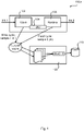
- Fig. 1 is a schematic diagram illustrating a computing system 100a according to embodiments.
- a current instruction (denoted Ins o; the notation Ins 1 is used for a next instruction) is processed by a pipeline issue stage 102.
- the issue stage 102 requests the processor's bus interface unit (BUI) 104 (also referred to as cache port) to fetch requested data and concurrently commands the sample fifo 106 (where fifo is short for first in first out) to register the current cycle count (denoted to; for the next instruction the corresponding cycle count is denoted ti).
- BUI bus interface unit
- the sample fifo 108 is commanded to sample the current cycle (C) again. This marks the end of the transaction for instruction Ins 0.
- the accumulated penalty time is read by the operating system (OS) scheduler, and stored in the cache penalty statistics that is used to take a scheduling decision.
- OS operating system
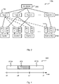
- Fig. 2 is a schematic diagram illustrating a computing system 100b according to embodiments.
- the computing system 100b comprises N6 number of caches 190, where cache 1 is shared by N2 number of processor cores (PC) from a cluster of processor cores 180, where cache 2 is shared by N 3 number of processor cores from the cluster of processor cores 180, where cache 3 is shared by N4 number of processor cores from the cluster of processor cores 180, and where cache N6 is shared by N5 number of processor cores from the cluster of processor cores 180.
- N1 number of different tasks 160 are repeatedly scheduled on the cluster of processor cores 180. In this respect, all numbers N1-N6 could be different. Alternatively, at least two of the numbers N1-N6 are equal.
- a controller 200 is provided for scheduling a task 150 from the plurality of tasks 160 to a processor core 170 of the cluster of processor cores 180.
- the embodiments disclosed herein thus relate to mechanisms for scheduling a task 150 from a plurality of tasks 160 to a processor core 170 of a cluster of processor cores 180.
- a controller 200 a method performed by the controller 200, a computer program product comprising code, for example in the form of a computer program, that when run on a controller 200, causes the controller 200 to perform the method.
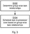
- Fig. 3 illustrating a method for scheduling a task 150 from a plurality of tasks 160 to a processor core 170 of a cluster of processor cores 180.
- the processor cores 180 share caches 190.
- the method is performed by the controller 200.
- the method is advantageously provided as a computer program 720.
- the method is based on determining task relationship between tasks 160 based on how well the tasks perform together in the caches 190.
- the controller is configured to perform step S102:
- S102: The controller 200 determines group-wise task relationships between the plurality of tasks 160 based on duration of cache misses resulting from running groups of the plurality of tasks 160 on processor cores 180 sharing the same cache 190.
- the method is further based on scheduling the task 150 with respect to its task relationship with the other tasks 160.
- the controller is configured to perform step S104:
- This method introduces a way to sample data enough to provide (real-time) updated information on which tasks of a plurality of tasks 160 are suited to run together, and also which tasks should avoid executing together in a cluster of processor cores 180.
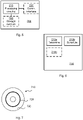
- Fig. 4 is a schematic diagram 400 illustrating duration of executing a task 150 in one of the processor cores 180 including the penalty for cache misses.
- execution of the task 150 starts at time and finishes at time ti. That is, the total duration of running the task is ti-to. This total duration includes the duration of cache misses, symbolically illustrated from time tc0 to time tc1.
- each individual task relationship is based on a ratio between the duration tc1-tc0 of cache misses and total duration ti-to of running one of the tasks.
- Fig. 4 is a simple illustration and does not necessarily illustrate practical execution of a task by a processor core; cache misses could occur any time between to and ti and may thus be spread out at a plurality of such chunks 420 between to and ti.
- the individual task relationship at time index n depends on the individual task relationship at time index n-1. That is, the individual task relationship at time index n for running TaskA on the processor core sharing cache X depends on the individual task relationship at time index n-1 for running task A on the processor core sharing cache X.
- A takes a value from 1 to N1 and X takes a value from 1 to N6.
- the individual task relationship is based on a ratio between the duration tc1-tc0 of cache misses and total duration ti-to of running one of the tasks and the individual task relationship at time index n for running Task A on the processor core sharing cache X depends on the individual task relationship at time index n-1 for running task A on the processor core sharing cache X .
- the value of k decides the speed with which the tasks will be associated with each other.
- k could be large enough to out-weight any of the effects of:
- the group-wise task is based on averaged individual task relationships.
- the caches 190 are shared by unequally many of the processor cores.
- N2, N3, N4, and N5 take values in a set comprising at least two different numbers such that Ni ⁇ Nj for at least one i, j in the set ⁇ 2, 3, 4, 5 ⁇ for i ⁇ j.
- clusters of processor cores 190 could be part of a digital signal processor.
- the cluster of processor cores 190 could be part of one single digital signal processor or of a cluster of digital signal processors.
- the controller 200 could be implemented in a control unit of the digital signal processor(s).
- the cluster of processor cores 190 is part of a cloud computing system.
- the computing system 100b is a cloud computing system.
- controller 200 could be implemented in a control unit of the cloud computing system.
- Fig. 5 schematically illustrates, in terms of a number of functional units, the components of a controller 200 according to an embodiment.
- Processing circuitry 210 is provided using any combination of one or more of a suitable central processing unit (CPU), multiprocessor, microcontroller, digital signal processor (DSP), etc., capable of executing software instructions stored in a computer program product 710 (as in Fig. 7 ), e.g. in the form of a storage medium 230.
- the processing circuitry 210 may further be provided as at least one application specific integrated circuit (ASIC), or field programmable gate array (FPGA).
- ASIC application specific integrated circuit
- FPGA field programmable gate array
- the processing circuitry 210 is configured to cause the controller 200 to perform a set of operations, or steps, S102-S104, as disclosed above.
- the storage medium 230 may store the set of operations
- the processing circuitry 210 may be configured to retrieve the set of operations from the storage medium 230 to cause the controller 200 to perform the set of operations.
- the set of operations may be provided as a set of executable instructions.
- modules 210a-210c may be implemented by the processing circuitry 210, possibly in cooperation with functional units 220 and/or 230.
- the processing circuitry 210 may thus be configured to from the storage medium 230 fetch instructions as provided by a functional module 210a-210c and to execute these instructions, thereby performing any steps as disclosed herein.
- the controller 200 may be provided as a standalone device or as a part of at least one further device. Further, a first portion of the instructions performed by the controller 200 may be executed in a first device, and a second portion of the of the instructions performed by the controller 200 may be executed in a second device; the herein disclosed embodiments are not limited to any particular number of devices on which the instructions performed by the controller 200 may be executed. Hence, the methods according to the herein disclosed embodiments are suitable to be performed by a controller 200 residing in a cloud computational environment. Therefore, although a single processing circuitry 210 is illustrated in Fig. 5 the processing circuitry 210 may be distributed among a plurality of devices, or nodes. The same applies to the functional modules 210a-210c of Fig. 6 and the computer program 720 of Fig. 7 (see below).
- Fig. 7 shows a computer program product 710 comprising computer readable storage medium 730.
- a computer program 720 can be stored, which computer program 720 causes the processing circuitry 210 and thereto operatively coupled entities and devices, such as the communications interface 220 and the storage medium 230, to execute methods according to embodiments described herein.
- the computer program 720 and/or computer program product 710 may thus provide means for performing any steps as herein disclosed.
Landscapes
- Engineering & Computer Science (AREA)
- Theoretical Computer Science (AREA)
- Software Systems (AREA)
- Physics & Mathematics (AREA)
- General Engineering & Computer Science (AREA)
- General Physics & Mathematics (AREA)
- Memory System Of A Hierarchy Structure (AREA)
- Multi Processors (AREA)
Description
- Embodiments presented herein relate to a method, a controller and a computer program product for scheduling a task from a plurality of tasks to a processor core of a cluster of processor cores, where the processor cores share caches.
- In general terms, a thread of execution can be defined as the smallest sequence of programmed instructions that can be managed independently by a scheduler, which is typically a part of the operating system. The implementation of threads and processes differs between operating systems, but in most cases a thread is a component of a process. Multiple threads can exist within one process, executing concurrently and sharing resources such as memory, while different processes do not share these resources. In particular, the threads of a process share its executable code and the values of its variables at any given time. Systems with a single processor generally implement multithreading by time slicing: the central processing unit (CPU) switches between different software threads. This context switching generally happens very often and rapidly enough that users perceive the threads or tasks as running in parallel. On a multiprocessor or multi-core system, i.e., a system using a cluster of processor cores, multiple threads can execute in parallel, with every processor or core executing a separate thread simultaneously; on a processor or core with hardware threads, separate software threads can also be executed concurrently by separate hardware threads.
- There exist different mechanisms for scheduling tasks to the cores. For example, depending on the core, cluster and system capacity, the scheduler could select an idle core, an idle cluster or adds more jobs to an already active cluster. It could also be possible to have static definitions on where to deploy a thread (i.e. to which core a task should be scheduled to).
- The threads may or may not share parts of the (cacheable memory) working-set and the threads may or may not introduce cache aliasing effects in certain combinations. Only having static definitions on where to deploy a thread can be made to take this situation into account. Scheduling based on static definitions provides the possibility to make optimal placement of the tasks to the cores, but could require big effort in careful studies of the working-set behavior for the individual threads in order to analyze the shared working-set usage. Furthermore, the common usage will differ with dynamic effects, impossible to capture with static analysis methods. Another possibility is to use system simulations to capture the required characteristics, but also this requires big efforts in terms of computational resources. This work needs to be repeated for each new software build.
- Hence, there is still a need for an improved scheduling of tasks for a cluster of processor cores.
- Document
US2011246995 A1 relates to scheduling threads sharing resources, by grouping threads together across resources in a way that reduces overall resource contention, thereby improving the instructions per cycle for all threads. - Document
US7487317 B1 relates to scheduling groups of threads to achieve low cache miss rates in a shared multithreaded cache. - An object of embodiments herein is to provide efficient scheduling of tasks for a cluster of processor cores.
- According to a first aspect there is presented a method for scheduling a task according to
claim 1. - According to a second aspect there is presented a controller for scheduling a task according to claim 10.
- According to a third aspect there is presented a computer program product according to
claim 11 and a computer readable storage medium on which the computer program is stored. The computer readable storage medium could be a non-transitory computer readable storage medium. - Advantageously this computer program product, method and this controller provide efficient scheduling of the task for a cluster of processor cores.
- Advantageously this computer program product, method and this controller enable scheduling of tasks to fit together.
- Advantageously this computer program product, method and this controller enable statistical data to be continuously sampled and learned by the controller how to schedule tasks for optimal cache performance.
- Advantageously this computer program product, method and this controller enable all-in-all memory performance to be enhanced by machine learning.
- Advantageously this computer program product, method and this controller is applicable for scheduling of tasks in complex systems that operate on data chunks and send it to the next task to operate on that data chunk.
- Advantageously this computer program product, method and this controller enable improved overall performance of the computing system in which the tasks are scheduled.
- Advantageously this computer program product, method and this controller enable improved power consumption of the computing system in which the tasks are scheduled.
- Advantageously this computer program product, method and this controller enable software optimizations aiming at cache performance not to be needed.
- It is to be noted that any feature of the first, second, and third aspects may be applied to any other aspect, wherever appropriate. Likewise, any advantage of the first aspect may equally apply to the second and/or third aspect, respectively, and vice versa. Other objectives, features and advantages of the enclosed embodiments will be apparent from the following detailed disclosure, from the attached dependent claims as well as from the drawings.
- Generally, all terms used in the claims are to be interpreted according to their ordinary meaning in the technical field, unless explicitly defined otherwise herein. All references to "a/an/the element, apparatus, component, means, step, etc." are to be interpreted openly as referring to at least one instance of the element, apparatus, component, means, step, etc., unless explicitly stated otherwise. The steps of any method disclosed herein do not have to be performed in the exact order disclosed, unless explicitly stated.
- The inventive concept is now described, by way of example, with reference to the accompanying drawings, in which:
-
Figs. 1 and2 are schematic diagram illustrating computing systems according to embodiments; -
Fig. 3 is a flowchart of methods according to embodiments; -
Fig. 4 is a schematic diagram illustrating a task execution including penalty for cache misses according to an embodiment; -
Fig. 5 is a schematic diagram showing functional units of a controller according to an embodiment; -
Fig. 6 is a schematic diagram showing functional modules of a controller according to an embodiment; and -
Fig. 7 shows one example of a computer program product comprising computer readable storage medium according to an embodiment. - The inventive concept will now be described more fully hereinafter with reference to the accompanying drawings, in which certain embodiments of the inventive concept are shown. These embodiments are provided by way of example so that this disclosure will be thorough and complete, and will fully convey the scope of the inventive concept to those skilled in the art. Like numbers refer to like elements throughout the description. Any step or feature illustrated by dashed lines should be regarded as optional.
-
Fig. 1 is a schematic diagram illustrating acomputing system 100a according to embodiments. When the processor pipeline is required to access data outside register banks, a current instruction (denoted Ins o; thenotation Ins 1 is used for a next instruction) is processed by apipeline issue stage 102. Theissue stage 102 requests the processor's bus interface unit (BUI) 104 (also referred to as cache port) to fetch requested data and concurrently commands the sample fifo 106 (where fifo is short for first in first out) to register the current cycle count (denoted to; for the next instruction the corresponding cycle count is denoted ti). At the pipeline receivestage 106, when the pipeline receives data from the BIU, thesample fifo 108 is commanded to sample the current cycle (C) again. This marks the end of the transaction forinstruction Ins 0. The sample fifo executes the subtraction dc = C-to, and requests the penalty time accumulator (PTA) 110 to add the result dc to its current value; its accumulated penalty time. The accumulated penalty time is read by the operating system (OS) scheduler, and stored in the cache penalty statistics that is used to take a scheduling decision. -
Fig. 2 is a schematic diagram illustrating acomputing system 100b according to embodiments. Thecomputing system 100b comprises N6 number of caches 190, wherecache 1 is shared by N2 number of processor cores (PC) from a cluster ofprocessor cores 180, wherecache 2 is shared by N3 number of processor cores from the cluster ofprocessor cores 180, wherecache 3 is shared by N4 number of processor cores from the cluster ofprocessor cores 180, and where cache N6 is shared by N5 number of processor cores from the cluster ofprocessor cores 180. N1 number ofdifferent tasks 160 are repeatedly scheduled on the cluster ofprocessor cores 180. In this respect, all numbers N1-N6 could be different. Alternatively, at least two of the numbers N1-N6 are equal. Acontroller 200 is provided for scheduling atask 150 from the plurality oftasks 160 to aprocessor core 170 of the cluster ofprocessor cores 180. - The embodiments disclosed herein thus relate to mechanisms for scheduling a
task 150 from a plurality oftasks 160 to aprocessor core 170 of a cluster ofprocessor cores 180. In order to obtain such mechanisms there is provided acontroller 200, a method performed by thecontroller 200, a computer program product comprising code, for example in the form of a computer program, that when run on acontroller 200, causes thecontroller 200 to perform the method. - Reference is now made to
Fig. 3 illustrating a method for scheduling atask 150 from a plurality oftasks 160 to aprocessor core 170 of a cluster ofprocessor cores 180. Theprocessor cores 180 share caches 190. The method is performed by thecontroller 200. The method is advantageously provided as acomputer program 720. - The method is based on determining task relationship between
tasks 160 based on how well the tasks perform together in the caches 190. Hence, the controller is configured to perform step S102:
S102: Thecontroller 200 determines group-wise task relationships between the plurality oftasks 160 based on duration of cache misses resulting from running groups of the plurality oftasks 160 onprocessor cores 180 sharing the same cache 190. - The method is further based on scheduling the
task 150 with respect to its task relationship with theother tasks 160. Hence, the controller is configured to perform step S104:
S104: Thecontroller 200 schedules thetask 150 to one of theprocessor cores 170 based on the group-wise task relationships of thetask 150. - This method introduces a way to sample data enough to provide (real-time) updated information on which tasks of a plurality of
tasks 160 are suited to run together, and also which tasks should avoid executing together in a cluster ofprocessor cores 180. This means that tasks are scheduled with respect to the relationship with other tasks. This relationship is in turn determined based on how well the tasks perform together in the caches 190. That is, instead of schedulingtasks 160 tocores 180, thetasks 160 are scheduled to caches 190 (associated with the cores 180). - Embodiments relating to further details of scheduling a
task 150 as performed by thecontroller 200 will now be disclosed. - The
task 150 is scheduled to theprocessor core 170 corresponding to the group-wise task relationship of the task with minimum value. Each group-wise task relationship is based on averaged individual task relationships. How to determine the individual task relationships will be disclosed next.Fig. 4 is a schematic diagram 400 illustrating duration of executing atask 150 in one of theprocessor cores 180 including the penalty for cache misses. In more detail, execution of thetask 150 starts at time and finishes at time ti. That is, the total duration of running the task is ti-to. This total duration includes the duration of cache misses, symbolically illustrated from time tc0 to time tc1. According to an embodiment each individual task relationship is based on a ratio between the duration tc1-tc0 of cache misses and total duration ti-to of running one of the tasks. - According to the illustration in
Fig. 4 the time for executing the task not considering cache misses is divided in twochunks chunk 420 corresponding to the penalty for cache misses. However, as the skilled person understands,Fig. 4 is a simple illustration and does not necessarily illustrate practical execution of a task by a processor core; cache misses could occur any time between to and ti and may thus be spread out at a plurality ofsuch chunks 420 between to and ti. - Further, the individual task relationship at time index n depends on the individual task relationship at time index n-1. That is, the individual task relationship at time index n for running TaskA on the processor core sharing cache X depends on the individual task relationship at time index n-1 for running task A on the processor core sharing cache X. In the example of
Fig. 2 , A takes a value from 1 to N1 and X takes a value from 1 to N6. - In view of the above, the individual task relationship is based on a ratio between the duration tc1-tc0 of cache misses and total duration ti-to of running one of the tasks and the individual task relationship at time index n for running Task A on the processor core sharing cache X depends on the individual task relationship at time index n-1 for running task A on the processor core sharing cache X. Hence, the individual task relationship at time index n for running task A on the processor core sharing cache X has a value R(A,X)[n] given by:

- There could be different ways to select the value of k. In general terms, the value of k decides the speed with which the tasks will be associated with each other. Typically k could be large enough to out-weight any of the effects of:
- several different tasks having been executed in the same cache as the task sampled at completion,
- functional variations in the completed task from one spawn to another (where a spawn is a function that loads and executes a new child process),
- functional variations in the other tasks running in the same cache from one spawn to another, and/or
- the distribution of run-length for the tasks in the computing system.
- As disclosed above, the group-wise task is based on averaged individual task relationships. Hence, the group-wise task relationship G(X)[n] at time n for cache X shared by
PC 1, PC2, ..., PC Nx for Task A, Task B, ..., Task Z is determined as
- For example, with reference to the illustrative example of
Fig. 2 , when a task oftype Task 1 has finished it execution inPC 1 ofCache 1, the entries for the relationship betweenTask 1 and Task 2 (which sharesCache 1 with Task 1) could be updated with a weighted average. Hence, according to an embodiment, group-wise task relationships for all tasks using the same one of the caches are updated every time one of the individual task relationships of this same one of the caches is updated. Then, for the illustrative example ofFig. 2 , the lower the number of the individual task relationship at time index n for runningTask 1 onprocessor core PC 1sharing cache 1 with processor core PC N2 on whichTask 2 is run, the more probable thatTasks 1 andTask 2 should share cache also in the future. That is, whenTask 1 is run onprocessor core PC 1 ofCache 1, an individual task relationship for runningTask 2 on processor core PC N2 ofCache 1 is also determined. That is, according to an embodiment there are as many individual task relationships per group-wise task relationship as there are processor cores per group-wise task relationship. Further, there are as many group-wise task relationships as there are caches. - There could be equally or unequally many caches per processor core. According to an embodiment all caches 190 are shared by equally many of the processor cores. Hence, according to this embodiment N2=N3=N4=N5. According to another embodiment the caches 190 are shared by unequally many of the processor cores. Hence, according to this embodiment N2, N3, N4, and N5 take values in a set comprising at least two different numbers such that Ni≠Nj for at least one i, j in the set {2, 3, 4, 5} for i≠j.
- There could be different kinds of tasks. According to an embodiment the tasks are run-to-completion tasks. Each one of the tasks could correspond to a software thread. Hence, according to an embodiment the tasks are software threads.
- There could be different kinds of clusters of processor cores 190. For example, the cluster of processor cores 190 could be part of a digital signal processor. The cluster of processor cores 190 could be part of one single digital signal processor or of a cluster of digital signal processors. Further in this respect, the
controller 200 could be implemented in a control unit of the digital signal processor(s). Additionally or alternatively, the cluster of processor cores 190 is part of a cloud computing system. Hence, according to an embodiment thecomputing system 100b is a cloud computing system. - Further in this respect, the
controller 200 could be implemented in a control unit of the cloud computing system. -
Fig. 5 schematically illustrates, in terms of a number of functional units, the components of acontroller 200 according to an embodiment.Processing circuitry 210 is provided using any combination of one or more of a suitable central processing unit (CPU), multiprocessor, microcontroller, digital signal processor (DSP), etc., capable of executing software instructions stored in a computer program product 710 (as inFig. 7 ), e.g. in the form of astorage medium 230. Theprocessing circuitry 210 may further be provided as at least one application specific integrated circuit (ASIC), or field programmable gate array (FPGA). - Particularly, the
processing circuitry 210 is configured to cause thecontroller 200 to perform a set of operations, or steps, S102-S104, as disclosed above. For example, thestorage medium 230 may store the set of operations, and theprocessing circuitry 210 may be configured to retrieve the set of operations from thestorage medium 230 to cause thecontroller 200 to perform the set of operations. The set of operations may be provided as a set of executable instructions. - Thus the
processing circuitry 210 is thereby arranged to execute methods as herein disclosed. Thestorage medium 230 may also comprise persistent storage, which, for example, can be any single one or combination of magnetic memory, optical memory, solid state memory or even remotely mounted memory. Thecontroller 200 may further comprise acommunications interface 220 at least configured for communications with entities of thecomputing system 100b, such as thetasks 160, the cluster ofprocessor cores 180, and the caches 190. As such thecommunications interface 220 may comprise one or more transmitters and receivers, comprising analogue and digital components. Theprocessing circuitry 210 controls the general operation of thecontroller 200 e.g. by sending data and control signals to thecommunications interface 220 and thestorage medium 230, by receiving data and reports from thecommunications interface 220, and by retrieving data and instructions from thestorage medium 230. Other components, as well as the related functionality, of thecontroller 200 are omitted in order not to obscure the concepts presented herein. -
Fig. 6 schematically illustrates, in terms of a number of functional modules, the components of acontroller 200 according to an embodiment. Thecontroller 200 ofFig. 6 comprises a number of functional modules; a determinemodule 210a configured to perform step S102, and aschedule module 210b configured to perform step S104. Thecontroller 200 ofFig. 6 may further comprise a number of optional functional modules, as symbolized byfunctional module 210c. In general terms, eachfunctional module 210a-210c may in one embodiment be implemented only in hardware or and in another embodiment with the help of software, i.e., the latter embodiment having computer program instructions stored on thestorage medium 230 which when run on the processing circuitry makes thecontroller 200 perform the corresponding steps mentioned above in conjunction withFig 6 . It should also be mentioned that even though the modules correspond to parts of a computer program, they do not need to be separate modules therein, but the way in which they are implemented in software is dependent on the programming language used. Preferably, one or more or allfunctional modules 210a-210c may be implemented by theprocessing circuitry 210, possibly in cooperation withfunctional units 220 and/or 230. Theprocessing circuitry 210 may thus be configured to from thestorage medium 230 fetch instructions as provided by afunctional module 210a-210c and to execute these instructions, thereby performing any steps as disclosed herein. - The
controller 200 may be provided as a standalone device or as a part of at least one further device. Further, a first portion of the instructions performed by thecontroller 200 may be executed in a first device, and a second portion of the of the instructions performed by thecontroller 200 may be executed in a second device; the herein disclosed embodiments are not limited to any particular number of devices on which the instructions performed by thecontroller 200 may be executed. Hence, the methods according to the herein disclosed embodiments are suitable to be performed by acontroller 200 residing in a cloud computational environment. Therefore, although asingle processing circuitry 210 is illustrated inFig. 5 theprocessing circuitry 210 may be distributed among a plurality of devices, or nodes. The same applies to thefunctional modules 210a-210c ofFig. 6 and thecomputer program 720 ofFig. 7 (see below). -
Fig. 7 shows acomputer program product 710 comprising computerreadable storage medium 730. On this computerreadable storage medium 730, acomputer program 720 can be stored, whichcomputer program 720 causes theprocessing circuitry 210 and thereto operatively coupled entities and devices, such as thecommunications interface 220 and thestorage medium 230, to execute methods according to embodiments described herein. Thecomputer program 720 and/orcomputer program product 710 may thus provide means for performing any steps as herein disclosed. - In the example of
Fig. 7 , thecomputer program product 710 is illustrated as an optical disc, such as a CD (compact disc) or a DVD (digital versatile disc) or a Blu-Ray disc. Thecomputer program product 710 could also be embodied as a memory, such as a random access memory (RAM), a read-only memory (ROM), an erasable programmable read-only memory (EPROM), or an electrically erasable programmable read-only memory (EEPROM) and more particularly as a non-volatile storage medium of a device in an external memory such as a USB (Universal Serial Bus) memory or a Flash memory, such as a compact Flash memory. Thus, while thecomputer program 720 is here schematically shown as a track on the depicted optical disk, thecomputer program 720 can be stored in any way which is suitable for thecomputer program product 710.
Claims (11)
- A method for scheduling a task (150) from a plurality of tasks (160) to a processor core (170) of a cluster of processor cores (180), the processor cores sharing caches (190), the method being performed by a controller (200), the method comprising:determining (S102) group-wise task relationships between the plurality of tasks based on a duration of cache misses resulting from running groups of the plurality of tasks on processor cores sharing the same cache; wherein each group-wise task relationship at atime index n is based on averaged individual task relationships at the time index n, wherein there are as many group-wise task relationships as there are caches, and wherein each individual task relationship is based on a ratio between the duration ,tc1-tc0, of cache misses and a total duration ,ti-to, of running one of the tasks, wherein an individual task relationship at the time index n for running a task A on a processor core sharing a cache X has a value R(A,X)[n] given by:
 scheduling (S104) the task to one of the processor cores based on its individual group-wise task relationship with the other tasks,wherein the task is scheduled to the processor core corresponding to the group-wise task relationship of the task with minimum value.
 - The method according to claim 1, wherein group-wise task relationships for all tasks using a same one of the caches are updated every time one of the individual task relationships of said same one of the caches is updated.
- The method according to any of claims 1 to 2, wherein there are as many individual task relationships per group-wise task relationship as there are processor cores per group-wise task relationship.
- The method according to any of the preceding claims, wherein all caches are shared by equally many of the processor cores.
- The method according to any of claims 1 to 3, wherein the caches are shared by unequally many of the processor cores.
- The method according to any of the preceding claims, wherein the tasks are run-to-completion tasks.
- The method according to any of the preceding claims, wherein the tasks are software threads.
- The method according to any of the preceding claims, wherein the cluster of processor cores is part of one single digital signal processor.
- The method according to any of claims 1 to 11, wherein the cluster of processor cores is part of a cloud computing system.
- A controller (200) for scheduling a task (150) from a plurality of tasks (160) to a processor core (170) of a cluster of processor cores (180), the processor cores sharing caches (190), the controller (200) comprising processing circuitry (210), the processing circuitry being configured to cause the controller (200) to:determine (S102) group-wise task relationships between the plurality of tasks based on a duration of cache misses resulting from running groups of the plurality of tasks on processor cores sharing the same cache; wherein each group-wise task relationship at a time index n is based on averaged individual task relationships at the time index n, wherein there are as many group-wise task relationships as there are caches,and wherein each individual task relationship is based on a ratio between the duration ,tc1-tc0, of cache misses and a total duration ,ti-to, of running one of the tasks,wherein an individual task relationship at the time index n for running a task A on a processor core sharing a cache X has a value R(A,X)[n] given by:
 where k>1 is a parameter, andschedule (S104) the task to one of the processor cores based on its individual group-wise task relationship with the other tasks,wherein the task is scheduled to the processor core corresponding to the group-wise task relationship of the task with minimum value.
 - A computer program product (710) comprising a computer program (720), and a computer readable storage medium (730) on which the computer program is stored, the computer program (720) for scheduling a task (150) from a plurality of tasks (160) to a processor core (170) of a cluster of processor cores (180), the processor cores sharing caches (190), the computer program comprising computer code which, when run on processing circuitry (210) of a controller (200), causes the controller (200) to:determine (S102) group-wise task relationships between the plurality of tasks based on a duration of cache misses resulting from running groups of the plurality of tasks on processor cores sharing the same cache; wherein each group-wise task relationship at a time index n is based on averaged individual task relationships at the time index n,wherein there are as many group-wise task relationships as there are caches, and wherein each individual task relationship is based on a ratio between the duration ,tc1-tc0, of cache misses and a total duration ,ti-to, of running one of the tasks,wherein a individual task relationship at the time index n for running a task A on a processor core sharing a cache X has a value R(A,X)[n] given by:
 where k>1 is a parameter, andschedule (S104) the task to one of the processor cores based on its individual group-wise task relationship with the other tasks,wherein the task is scheduled to the processor core corresponding to the group-wise task relationship of the task with minimum value.
Applications Claiming Priority (1)
| Application Number | Priority Date | Filing Date | Title |
|---|---|---|---|
| PCT/EP2016/074174 WO2018068809A1 (en) | 2016-10-10 | 2016-10-10 | Task scheduling |
Publications (2)
| Publication Number | Publication Date |
|---|---|
| EP3523720A1 EP3523720A1 (en) | 2019-08-14 |
| EP3523720B1 true EP3523720B1 (en) | 2022-07-27 |
Family
ID=57113367
Family Applications (1)
| Application Number | Title | Priority Date | Filing Date |
|---|---|---|---|
| EP16778411.5A Active EP3523720B1 (en) | 2016-10-10 | 2016-10-10 | Task scheduling |
Country Status (4)
| Country | Link |
|---|---|
| US (2) | US10877808B2 (en) |
| EP (1) | EP3523720B1 (en) |
| CN (1) | CN109791506B (en) |
| WO (1) | WO2018068809A1 (en) |
Families Citing this family (7)
| Publication number | Priority date | Publication date | Assignee | Title |
|---|---|---|---|---|
| US11330042B2 (en) | 2018-05-17 | 2022-05-10 | International Business Machines Corporation | Optimizing dynamic resource allocations for storage-dependent workloads in disaggregated data centers |
| US11221886B2 (en) * | 2018-05-17 | 2022-01-11 | International Business Machines Corporation | Optimizing dynamical resource allocations for cache-friendly workloads in disaggregated data centers |
| CN109145053B (en) * | 2018-08-01 | 2021-03-23 | 创新先进技术有限公司 | Data processing method and device, client and server |
| CN112130977B (en) * | 2020-09-25 | 2022-08-02 | 山东云海国创云计算装备产业创新中心有限公司 | Task scheduling method, device, equipment and medium |
| WO2022199823A1 (en) * | 2021-03-25 | 2022-09-29 | Telefonaktiebolaget Lm Ericsson (Publ) | Task scheduling |
| US20230067109A1 (en) * | 2021-08-30 | 2023-03-02 | Apple Inc. | Performance islands for cpu clusters |
| WO2024168572A1 (en) * | 2023-02-15 | 2024-08-22 | Qualcomm Incorporated | System and method for micro-architecture aware task scheduling |
Family Cites Families (10)
| Publication number | Priority date | Publication date | Assignee | Title |
|---|---|---|---|---|
| US6408402B1 (en) * | 1994-03-22 | 2002-06-18 | Hyperchip Inc. | Efficient direct replacement cell fault tolerant architecture |
| US6938252B2 (en) * | 2000-12-14 | 2005-08-30 | International Business Machines Corporation | Hardware-assisted method for scheduling threads using data cache locality |
| JP2002189650A (en) * | 2000-12-20 | 2002-07-05 | Hitachi Ltd | Method and device for controlling computer, and recording medium stored with processing program therefor |
| US7487317B1 (en) | 2005-11-03 | 2009-02-03 | Sun Microsystems, Inc. | Cache-aware scheduling for a chip multithreading processor |
| US7689773B2 (en) * | 2006-11-30 | 2010-03-30 | Sun Microsystems, Inc. | Methods and apparatus for estimating fair cache miss rates on a chip multiprocessor |
| US8028286B2 (en) * | 2006-11-30 | 2011-09-27 | Oracle America, Inc. | Methods and apparatus for scheduling threads on multicore processors under fair distribution of cache and other shared resources of the processors |
| US8429665B2 (en) | 2010-03-19 | 2013-04-23 | Vmware, Inc. | Cache performance prediction, partitioning and scheduling based on cache pressure of threads |
| US8533719B2 (en) * | 2010-04-05 | 2013-09-10 | Oracle International Corporation | Cache-aware thread scheduling in multi-threaded systems |
| US8898390B2 (en) | 2011-03-08 | 2014-11-25 | Intel Corporation | Scheduling workloads based on cache asymmetry |
| CN104995603A (en) * | 2013-11-14 | 2015-10-21 | 联发科技股份有限公司 | Task scheduling method and related non-transitory computer readable medium for dispatching task in multi-core processor system based at least partly on distribution of tasks sharing same data and/or accessing same memory address (ES) |
-
2016
- 2016-10-10 CN CN201680089896.2A patent/CN109791506B/en not_active Expired - Fee Related
- 2016-10-10 WO PCT/EP2016/074174 patent/WO2018068809A1/en active Application Filing
- 2016-10-10 EP EP16778411.5A patent/EP3523720B1/en active Active
- 2016-10-10 US US16/340,486 patent/US10877808B2/en active Active
-
2020
- 2020-11-25 US US17/104,766 patent/US20210081248A1/en not_active Abandoned
Also Published As
| Publication number | Publication date |
|---|---|
| EP3523720A1 (en) | 2019-08-14 |
| CN109791506A (en) | 2019-05-21 |
| US10877808B2 (en) | 2020-12-29 |
| US20190243689A1 (en) | 2019-08-08 |
| US20210081248A1 (en) | 2021-03-18 |
| WO2018068809A1 (en) | 2018-04-19 |
| CN109791506B (en) | 2023-05-09 |
Similar Documents
| Publication | Publication Date | Title |
|---|---|---|
| EP3523720B1 (en) | Task scheduling | |
| US8046775B2 (en) | Event-based bandwidth allocation mode switching method and apparatus | |
| US9632836B2 (en) | Scheduling applications in a clustered computer system | |
| US9652243B2 (en) | Predicting out-of-order instruction level parallelism of threads in a multi-threaded processor | |
| CA2946775A1 (en) | Automated server workload management using machine learning | |
| US10606797B2 (en) | Systems and methods for implementing an intelligence processing computing architecture | |
| US20230127112A1 (en) | Sub-idle thread priority class | |
| US20160357669A1 (en) | Flushing control within a multi-threaded processor | |
| US11537429B2 (en) | Sub-idle thread priority class | |
| CN101689124A (en) | Thread de-emphasis instruction for multithreaded processor | |
| CN109634714B (en) | Intelligent scheduling method and device | |
| US10203988B2 (en) | Adaptive parallelism of task execution on machines with accelerators | |
| US10120719B2 (en) | Managing resource consumption in a computing system | |
| US10896130B2 (en) | Response times in asynchronous I/O-based software using thread pairing and co-execution | |
| CN117421129B (en) | Service execution method and device based on heterogeneous storage cluster and electronic equipment | |
| KR101765830B1 (en) | Multi-core system and method for driving the same | |
| KR101892273B1 (en) | Apparatus and method for thread progress tracking | |
| US20240184631A1 (en) | Task Scheduling | |
| EP4035004A1 (en) | Shared resource allocation in a multi-threaded microprocessor | |
| CN118747088A (en) | Signal processing method, device, equipment and medium for instruction multithreading transmission | |
| Abeydeera | Optimizing throughput architectures for speculative parallelism | |
| Arora et al. | Scheduling simulations: An experimental approach to time-sharing multiprocessor scheduling schemes | |
| CN116700135A (en) | Method and device for testing task scheduling mode of programmable logic controller | |
| Bharathi et al. | Analysis of Scheduling the Independent CCHBs for Partially Reconfigurable FPGA |
Legal Events
| Date | Code | Title | Description |
|---|---|---|---|
| STAA | Information on the status of an ep patent application or granted ep patent |
Free format text: STATUS: THE INTERNATIONAL PUBLICATION HAS BEEN MADE |
|
| PUAI | Public reference made under article 153(3) epc to a published international application that has entered the european phase |
Free format text: ORIGINAL CODE: 0009012 |
|
| STAA | Information on the status of an ep patent application or granted ep patent |
Free format text: STATUS: REQUEST FOR EXAMINATION WAS MADE |
|
| 17P | Request for examination filed |
Effective date: 20190404 |
|
| AK | Designated contracting states |
Kind code of ref document: A1 Designated state(s): AL AT BE BG CH CY CZ DE DK EE ES FI FR GB GR HR HU IE IS IT LI LT LU LV MC MK MT NL NO PL PT RO RS SE SI SK SM TR |
|
| AX | Request for extension of the european patent |
Extension state: BA ME |
|
| DAV | Request for validation of the european patent (deleted) | ||
| DAX | Request for extension of the european patent (deleted) | ||
| STAA | Information on the status of an ep patent application or granted ep patent |
Free format text: STATUS: EXAMINATION IS IN PROGRESS |
|
| 17Q | First examination report despatched |
Effective date: 20210804 |
|
| STAA | Information on the status of an ep patent application or granted ep patent |
Free format text: STATUS: EXAMINATION IS IN PROGRESS |
|
| GRAP | Despatch of communication of intention to grant a patent |
Free format text: ORIGINAL CODE: EPIDOSNIGR1 |
|
| STAA | Information on the status of an ep patent application or granted ep patent |
Free format text: STATUS: GRANT OF PATENT IS INTENDED |
|
| INTG | Intention to grant announced |
Effective date: 20220315 |
|
| GRAS | Grant fee paid |
Free format text: ORIGINAL CODE: EPIDOSNIGR3 |
|
| GRAA | (expected) grant |
Free format text: ORIGINAL CODE: 0009210 |
|
| STAA | Information on the status of an ep patent application or granted ep patent |
Free format text: STATUS: THE PATENT HAS BEEN GRANTED |
|
| AK | Designated contracting states |
Kind code of ref document: B1 Designated state(s): AL AT BE BG CH CY CZ DE DK EE ES FI FR GB GR HR HU IE IS IT LI LT LU LV MC MK MT NL NO PL PT RO RS SE SI SK SM TR |
|
| REG | Reference to a national code |
Ref country code: CH Ref legal event code: EP |
|
| REG | Reference to a national code |
Ref country code: AT Ref legal event code: REF Ref document number: 1507517 Country of ref document: AT Kind code of ref document: T Effective date: 20220815 |
|
| REG | Reference to a national code |
Ref country code: NL Ref legal event code: FP |
|
| REG | Reference to a national code |
Ref country code: DE Ref legal event code: R096 Ref document number: 602016073807 Country of ref document: DE |
|
| REG | Reference to a national code |
Ref country code: IE Ref legal event code: FG4D |
|
| REG | Reference to a national code |
Ref country code: LT Ref legal event code: MG9D |
|
| PG25 | Lapsed in a contracting state [announced via postgrant information from national office to epo] |
Ref country code: SE Free format text: LAPSE BECAUSE OF FAILURE TO SUBMIT A TRANSLATION OF THE DESCRIPTION OR TO PAY THE FEE WITHIN THE PRESCRIBED TIME-LIMIT Effective date: 20220727 Ref country code: RS Free format text: LAPSE BECAUSE OF FAILURE TO SUBMIT A TRANSLATION OF THE DESCRIPTION OR TO PAY THE FEE WITHIN THE PRESCRIBED TIME-LIMIT Effective date: 20220727 Ref country code: PT Free format text: LAPSE BECAUSE OF FAILURE TO SUBMIT A TRANSLATION OF THE DESCRIPTION OR TO PAY THE FEE WITHIN THE PRESCRIBED TIME-LIMIT Effective date: 20221128 Ref country code: NO Free format text: LAPSE BECAUSE OF FAILURE TO SUBMIT A TRANSLATION OF THE DESCRIPTION OR TO PAY THE FEE WITHIN THE PRESCRIBED TIME-LIMIT Effective date: 20221027 Ref country code: LV Free format text: LAPSE BECAUSE OF FAILURE TO SUBMIT A TRANSLATION OF THE DESCRIPTION OR TO PAY THE FEE WITHIN THE PRESCRIBED TIME-LIMIT Effective date: 20220727 Ref country code: LT Free format text: LAPSE BECAUSE OF FAILURE TO SUBMIT A TRANSLATION OF THE DESCRIPTION OR TO PAY THE FEE WITHIN THE PRESCRIBED TIME-LIMIT Effective date: 20220727 Ref country code: FI Free format text: LAPSE BECAUSE OF FAILURE TO SUBMIT A TRANSLATION OF THE DESCRIPTION OR TO PAY THE FEE WITHIN THE PRESCRIBED TIME-LIMIT Effective date: 20220727 Ref country code: ES Free format text: LAPSE BECAUSE OF FAILURE TO SUBMIT A TRANSLATION OF THE DESCRIPTION OR TO PAY THE FEE WITHIN THE PRESCRIBED TIME-LIMIT Effective date: 20220727 |
|
| REG | Reference to a national code |
Ref country code: AT Ref legal event code: MK05 Ref document number: 1507517 Country of ref document: AT Kind code of ref document: T Effective date: 20220727 |
|
| PG25 | Lapsed in a contracting state [announced via postgrant information from national office to epo] |
Ref country code: PL Free format text: LAPSE BECAUSE OF FAILURE TO SUBMIT A TRANSLATION OF THE DESCRIPTION OR TO PAY THE FEE WITHIN THE PRESCRIBED TIME-LIMIT Effective date: 20220727 Ref country code: IS Free format text: LAPSE BECAUSE OF FAILURE TO SUBMIT A TRANSLATION OF THE DESCRIPTION OR TO PAY THE FEE WITHIN THE PRESCRIBED TIME-LIMIT Effective date: 20221127 Ref country code: HR Free format text: LAPSE BECAUSE OF FAILURE TO SUBMIT A TRANSLATION OF THE DESCRIPTION OR TO PAY THE FEE WITHIN THE PRESCRIBED TIME-LIMIT Effective date: 20220727 Ref country code: GR Free format text: LAPSE BECAUSE OF FAILURE TO SUBMIT A TRANSLATION OF THE DESCRIPTION OR TO PAY THE FEE WITHIN THE PRESCRIBED TIME-LIMIT Effective date: 20221028 |
|
| PG25 | Lapsed in a contracting state [announced via postgrant information from national office to epo] |
Ref country code: SM Free format text: LAPSE BECAUSE OF FAILURE TO SUBMIT A TRANSLATION OF THE DESCRIPTION OR TO PAY THE FEE WITHIN THE PRESCRIBED TIME-LIMIT Effective date: 20220727 Ref country code: RO Free format text: LAPSE BECAUSE OF FAILURE TO SUBMIT A TRANSLATION OF THE DESCRIPTION OR TO PAY THE FEE WITHIN THE PRESCRIBED TIME-LIMIT Effective date: 20220727 Ref country code: DK Free format text: LAPSE BECAUSE OF FAILURE TO SUBMIT A TRANSLATION OF THE DESCRIPTION OR TO PAY THE FEE WITHIN THE PRESCRIBED TIME-LIMIT Effective date: 20220727 Ref country code: CZ Free format text: LAPSE BECAUSE OF FAILURE TO SUBMIT A TRANSLATION OF THE DESCRIPTION OR TO PAY THE FEE WITHIN THE PRESCRIBED TIME-LIMIT Effective date: 20220727 Ref country code: AT Free format text: LAPSE BECAUSE OF FAILURE TO SUBMIT A TRANSLATION OF THE DESCRIPTION OR TO PAY THE FEE WITHIN THE PRESCRIBED TIME-LIMIT Effective date: 20220727 |
|
| REG | Reference to a national code |
Ref country code: DE Ref legal event code: R097 Ref document number: 602016073807 Country of ref document: DE |
|
| PG25 | Lapsed in a contracting state [announced via postgrant information from national office to epo] |
Ref country code: SK Free format text: LAPSE BECAUSE OF FAILURE TO SUBMIT A TRANSLATION OF THE DESCRIPTION OR TO PAY THE FEE WITHIN THE PRESCRIBED TIME-LIMIT Effective date: 20220727 Ref country code: MC Free format text: LAPSE BECAUSE OF FAILURE TO SUBMIT A TRANSLATION OF THE DESCRIPTION OR TO PAY THE FEE WITHIN THE PRESCRIBED TIME-LIMIT Effective date: 20220727 Ref country code: EE Free format text: LAPSE BECAUSE OF FAILURE TO SUBMIT A TRANSLATION OF THE DESCRIPTION OR TO PAY THE FEE WITHIN THE PRESCRIBED TIME-LIMIT Effective date: 20220727 |
|
| REG | Reference to a national code |
Ref country code: CH Ref legal event code: PL |
|
| PLBE | No opposition filed within time limit |
Free format text: ORIGINAL CODE: 0009261 |
|
| STAA | Information on the status of an ep patent application or granted ep patent |
Free format text: STATUS: NO OPPOSITION FILED WITHIN TIME LIMIT |
|
| REG | Reference to a national code |
Ref country code: BE Ref legal event code: MM Effective date: 20221031 |
|
| P01 | Opt-out of the competence of the unified patent court (upc) registered |
Effective date: 20230523 |
|
| PG25 | Lapsed in a contracting state [announced via postgrant information from national office to epo] |
Ref country code: LU Free format text: LAPSE BECAUSE OF NON-PAYMENT OF DUE FEES Effective date: 20221010 Ref country code: AL Free format text: LAPSE BECAUSE OF FAILURE TO SUBMIT A TRANSLATION OF THE DESCRIPTION OR TO PAY THE FEE WITHIN THE PRESCRIBED TIME-LIMIT Effective date: 20220727 |
|
| 26N | No opposition filed |
Effective date: 20230502 |
|
| PG25 | Lapsed in a contracting state [announced via postgrant information from national office to epo] |
Ref country code: LI Free format text: LAPSE BECAUSE OF NON-PAYMENT OF DUE FEES Effective date: 20221031 Ref country code: FR Free format text: LAPSE BECAUSE OF NON-PAYMENT OF DUE FEES Effective date: 20221031 Ref country code: CH Free format text: LAPSE BECAUSE OF NON-PAYMENT OF DUE FEES Effective date: 20221031 |
|
| PG25 | Lapsed in a contracting state [announced via postgrant information from national office to epo] |
Ref country code: SI Free format text: LAPSE BECAUSE OF FAILURE TO SUBMIT A TRANSLATION OF THE DESCRIPTION OR TO PAY THE FEE WITHIN THE PRESCRIBED TIME-LIMIT Effective date: 20220727 |
|
| PG25 | Lapsed in a contracting state [announced via postgrant information from national office to epo] |
Ref country code: BE Free format text: LAPSE BECAUSE OF NON-PAYMENT OF DUE FEES Effective date: 20221031 |
|
| PG25 | Lapsed in a contracting state [announced via postgrant information from national office to epo] |
Ref country code: IE Free format text: LAPSE BECAUSE OF NON-PAYMENT OF DUE FEES Effective date: 20221010 |
|
| PGFP | Annual fee paid to national office [announced via postgrant information from national office to epo] |
Ref country code: NL Payment date: 20231026 Year of fee payment: 8 |
|
| PGFP | Annual fee paid to national office [announced via postgrant information from national office to epo] |
Ref country code: GB Payment date: 20231027 Year of fee payment: 8 |
|
| PGFP | Annual fee paid to national office [announced via postgrant information from national office to epo] |
Ref country code: DE Payment date: 20231027 Year of fee payment: 8 |
|
| PG25 | Lapsed in a contracting state [announced via postgrant information from national office to epo] |
Ref country code: HU Free format text: LAPSE BECAUSE OF FAILURE TO SUBMIT A TRANSLATION OF THE DESCRIPTION OR TO PAY THE FEE WITHIN THE PRESCRIBED TIME-LIMIT; INVALID AB INITIO Effective date: 20161010 |
|
| PG25 | Lapsed in a contracting state [announced via postgrant information from national office to epo] |
Ref country code: CY Free format text: LAPSE BECAUSE OF FAILURE TO SUBMIT A TRANSLATION OF THE DESCRIPTION OR TO PAY THE FEE WITHIN THE PRESCRIBED TIME-LIMIT Effective date: 20220727 |
|
| PG25 | Lapsed in a contracting state [announced via postgrant information from national office to epo] |
Ref country code: MK Free format text: LAPSE BECAUSE OF FAILURE TO SUBMIT A TRANSLATION OF THE DESCRIPTION OR TO PAY THE FEE WITHIN THE PRESCRIBED TIME-LIMIT Effective date: 20220727 Ref country code: IT Free format text: LAPSE BECAUSE OF FAILURE TO SUBMIT A TRANSLATION OF THE DESCRIPTION OR TO PAY THE FEE WITHIN THE PRESCRIBED TIME-LIMIT Effective date: 20220727 |
|
| PG25 | Lapsed in a contracting state [announced via postgrant information from national office to epo] |
Ref country code: TR Free format text: LAPSE BECAUSE OF FAILURE TO SUBMIT A TRANSLATION OF THE DESCRIPTION OR TO PAY THE FEE WITHIN THE PRESCRIBED TIME-LIMIT Effective date: 20220727 |
|
| PG25 | Lapsed in a contracting state [announced via postgrant information from national office to epo] |
Ref country code: BG Free format text: LAPSE BECAUSE OF FAILURE TO SUBMIT A TRANSLATION OF THE DESCRIPTION OR TO PAY THE FEE WITHIN THE PRESCRIBED TIME-LIMIT Effective date: 20220727 |
|
| PG25 | Lapsed in a contracting state [announced via postgrant information from national office to epo] |
Ref country code: MT Free format text: LAPSE BECAUSE OF FAILURE TO SUBMIT A TRANSLATION OF THE DESCRIPTION OR TO PAY THE FEE WITHIN THE PRESCRIBED TIME-LIMIT Effective date: 20220727 |