EP3523593B1 - Einzelladerschlossfanganordnung einer feuerwaffe und verfahren zum betrieb - Google Patents
Einzelladerschlossfanganordnung einer feuerwaffe und verfahren zum betrieb Download PDFInfo
- Publication number
- EP3523593B1 EP3523593B1 EP17859248.1A EP17859248A EP3523593B1 EP 3523593 B1 EP3523593 B1 EP 3523593B1 EP 17859248 A EP17859248 A EP 17859248A EP 3523593 B1 EP3523593 B1 EP 3523593B1
- Authority
- EP
- European Patent Office
- Prior art keywords
- firearm
- catch
- plate
- bolt
- spring
- Prior art date
- Legal status (The legal status is an assumption and is not a legal conclusion. Google has not performed a legal analysis and makes no representation as to the accuracy of the status listed.)
- Active
Links
Images


Classifications
-
- F—MECHANICAL ENGINEERING; LIGHTING; HEATING; WEAPONS; BLASTING
- F41—WEAPONS
- F41A—FUNCTIONAL FEATURES OR DETAILS COMMON TO BOTH SMALLARMS AND ORDNANCE, e.g. CANNONS; MOUNTINGS FOR SMALLARMS OR ORDNANCE
- F41A17/00—Safety arrangements, e.g. safeties
- F41A17/42—Safeties for locking the breech-block or bolt in a safety position
-
- F—MECHANICAL ENGINEERING; LIGHTING; HEATING; WEAPONS; BLASTING
- F41—WEAPONS
- F41A—FUNCTIONAL FEATURES OR DETAILS COMMON TO BOTH SMALLARMS AND ORDNANCE, e.g. CANNONS; MOUNTINGS FOR SMALLARMS OR ORDNANCE
- F41A3/00—Breech mechanisms, e.g. locks
- F41A3/64—Mounting of breech-blocks; Accessories for breech-blocks or breech-block mountings
- F41A3/72—Operating handles or levers; Mounting thereof in breech-blocks or bolts
-
- F—MECHANICAL ENGINEERING; LIGHTING; HEATING; WEAPONS; BLASTING
- F41—WEAPONS
- F41A—FUNCTIONAL FEATURES OR DETAILS COMMON TO BOTH SMALLARMS AND ORDNANCE, e.g. CANNONS; MOUNTINGS FOR SMALLARMS OR ORDNANCE
- F41A19/00—Firing or trigger mechanisms; Cocking mechanisms
- F41A19/06—Mechanical firing mechanisms, e.g. counterrecoil firing, recoil actuated firing mechanisms
- F41A19/42—Mechanical firing mechanisms, e.g. counterrecoil firing, recoil actuated firing mechanisms having at least one hammer
- F41A19/43—Mechanical firing mechanisms, e.g. counterrecoil firing, recoil actuated firing mechanisms having at least one hammer in bolt-action guns
- F41A19/46—Arrangements for the selection of automatic or semi-automatic fire
Definitions
- the present invention relates generally to a firearm single-shot bolt catch assembly and method of operation. More so, the automatic firearm single-shot bolt catch assembly utilizes a tensioned spring that operates with a bolt catch; whereby the tension from the spring works to pivotally articulate a plate in the bolt catch to a catch position, which restricts the recoiling bolt carrier group in linear path of the firearm; whereby the tension from the spring presses the plate upwardly into the linear path to restrict the passage of, and hold, the bolt carrier group towards the rearward end of the firearm; whereby the restriction of movement inhibits automated recoiling responses from the bolt carrier group, consequently creating a single-shot mode by disabling the automated firing sequence of the firearm; and whereby applying force to a lever in the bolt catch overcomes the spring bias to displace the plate out of the linear path followed by the bolt carrier group.
- a firearm is a portable gun that discharges projectiles that are driven by the action of an explosive force caused by pressure during the discharge of ammunition.
- An automatic firearm includes a firearm that continues to load and fire cartridges from its magazine as long as the trigger is depressed and until the magazine is depleted of available ammunition.
- a bolt is the part of a repeating, breech-loading firearm that blocks the rear of the chamber while the propellant burns and moves to facilitate loading of cartridges from the magazine.
- Automatic and semi-automatic firearms are provided with a bolt catch which retains the bolt in the open position upon firing the last round in a magazine. The bolt is thereafter manually released after a fresh magazine is inserted, so that a round is chambered in readiness for firing.
- locking the bolt carrier group in its rearward position allows the user to look into the ejection port of the firearm and inspect the chamber for a live round or to clear an operational malfunction. Once a loaded magazine is inserted into the receiver, or a malfunction is cleared, the user needs an efficient means for releasing the bolt carrier group from the locked-back position.
- US Patent Number 8,985,005 describes a mechanism for a repeating firearm that includes a bolt catch configured to restrict motion of the bolt carrier.
- the bolt catch is also configured to engage with the trigger when the bolt carrier is released to restrict motion of the trigger and prevent discharge of the firearm.
- the invention is a firearm single-shot bolt catch assembly according to claim 1 and its associated method of operation according to claim 11.
- Illustrative embodiments of the disclosure are generally directed to a firearm single-shot bolt catch assembly and method of operation.
- the automatic firearm single-shot bolt catch assembly uses a tensioned spring that operates with a bolt catch. The tension from the spring works to pivotally articulate a plate in the bolt catch to a catch position, which restricts the recoiling bolt carrier group in linear path of the firearm. The tension from the spring presses the plate upwardly into the linear path to restrict the passage of, and hold, the bolt carrier group towards the rearward end of the firearm.
- firearm single-shot bolt catch assembly provides a bolt catch operational with a firearm.
- the bolt catch comprises a plate and a lever.
- the plate is defined by a plate first end, a plate second end, a top edge, and a bottom edge forming a spring cavity.
- the lever is defined by a lever first end, a lever second end, and a middle region forming an aperture. The middle region of the lever joins with the plate in a generally coplanar relationship.
- the automatic firearm single-shot bolt catch assembly further comprises a spring that detachably fits inside the spring cavity at the bottom edge of the plate.
- the spring is tensioned to bias the plate into a linear path followed by a bolt carrier group of a firearm. This restrictive disposition of the plate restricts the bolt carrier group at a rearward end of the firearm. Furthermore, applying force to the lever pivotally articulates the plate out of the linear path followed by the bolt carrier group.
- One objective of the present invention is to reconfigure an automatic rifle pattern from an automatic or semi-automatic mode, to a single-shot mode.
- Another objective is to adapt an automatic or semi-automatic firearm to be legal.
- Yet another objective is to enable facilitated installation of a bolt catch into the receiver slot on the side of the firearm.
- Another objective is to enable facilitated release of the bolt carrier group from a linear path in the firearm through application of force on the lever with the thumb.
- Yet another objective is to provide a spring cavity in the bottom edge of the plate and a tensioned spring that fits into the spring cavity.
- Yet another objective is to provide an inexpensive to manufacture automatic firearm single-shot bolt catch assembly.
- a firearm single-shot bolt catch assembly 100 and method 800 of operation allows a firearm 200 to convert from an automatic mode to a single-shot mode by restricting movement of a bolt carrier group 202 that recoils forward from a rearward end 220 of a firearm 200 after discharging a projectile.
- Assembly 100 and method 800 works to automatically restrict bolt carrier group 202 to the rearward end 220 of firearm 200 with a spring tensioned plate 114; and then enables manual release of the bolt carrier group 202 to a release position 218 through application of force on a lever 104, so as to enable single-shot discharges.
- This single-shot mode allows a banned automatic firearm 300 to operate as a legal firearm 200.
- firearm single-shot bolt catch assembly 100 leverages the tensional forces inherent in a spring 126 with a bolt catch 102 operational in the firearm 200.
- the tension from spring 126 works to displace, or pivotally articulate, a plate 114 in the bolt catch 102 to a catch position 216, which restricts bolt carrier group 202 from recoiling forward along a linear path 214 that forms longitudinally along the rearward end 220 firearm 200. It is this restriction of automated recoil that converts firearm 200 into a single-shot mode.
- the tension from spring 126 displaces, or pivotally articulates, the plate 114 upwardly into linear path 214 to restrict bolt carrier group 202 at the rearward end 220 of firearm 200.
- This restriction of movement inhibits automated recoiling responses from bolt carrier group 202, consequently creating a single-shot mode by disabling the automated firing sequence of the firearm 200.
- the spring bias on plate 114 is overcome, enabling pivotal articulation of the plate 114, out of the linear path 214, and into a release position 218. Release position 218 enables forward recoil by bolt carrier group 202.
- assembly 100 is especially useful for converting a banned automatic firearm 300 to a legal single-shot firearm 200.
- banned features include telescoping/foldable stocks, excessive grips, bayonets, and muzzled and threaded barrels. Examples of banned firearms are shown in FIG.
- FIG. 3 illustrating: an automatic firearm 300 having a folding stock 302; an automatic firearm 300 having a second handgrip 304; an automatic firearm 300 having a capacity to attach a magazine 306 outside the pistol grip, and a shroud (not shown) that is attached to or completely encircles the barrel and that permits the shooter to hold the firearm with the non-textured grip surface hand without being burned.
- the automatic firearm 300 may have a telescoping stock (not shown); an automatic firearm having a protruding pistol grip 308; an automatic firearm 300 having a thumb spring cavity stock (not shown); an automatic firearm 300 having a threaded barrel 310 that can accept accessories, such as flash suppressors, muzzle brakes, and compensators; and an automatic firearm 300 having a bayonet mount 312.
- the present disclosure works to adapt the banned automatic firearm 300 described above, to a legal single-shot firearm 200 by restricting forward recoiling of the bolt carrier group, and consequently limiting the number of shots fired in rapid succession.
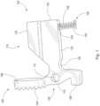
- the assembly 100 comprises a bolt catch 102 that is insertable through a receiver slot 206 in the side 204 of firearm 200.
- Bolt catch 102 is operational in a linear path 214 of firearm 200 followed by bolt carrier group 202.
- the essence of assembly is to pivotally displace bolt catch 102 in and out of path 214 followed by bolt carrier group 202 through use of a tensioned spring 126 that biases bolt catch 102 into the path 214, and a thumb-controlled lever 104 that displaces bolt catch 102 from the path 214.
- bolt catch 102 comprises substantially two components fixedly joined together - a plate 114 and a lever 104.
- Lever 104 is generally elongated and flat, forming a surface for the thumb or other digits of the hand to manipulate bolt catch 102.
- lever 104 functions primarily to enable manipulation of bolt catch 102.
- lever 104 may be defined by a first end 106 having a textured grip surface 134, a middle region 110 forming an aperture 112, and a second end 108.
- a pin 132 may pass through aperture 112 to enable insertion and attachment of bolt catch 102 to a receiver slot 206 forming on the side 204 of the firearm 200.
- Pin 132 may include a cotter pin, a role pin, and a fastening mechanism known in the art.
- Plate 114 forms integrally with the lever 104, forming a unitary component to effectively restrain and release the bolt carrier group 202 along linear path 214 of firearm 200.
- the plate 114 is generally flat and coplanar with lever 104. Plate 114 functions primarily to restrict linear displacement of bolt carrier group 202 at the rearward end 220 of firearm.
- plate 114 may be defined by a top edge 120 forming a lip 136, a bottom edge 122, a plate first end 116, and a plate second end 118.
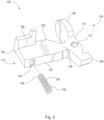
- the lip 136 at top edge 120 of plate 114 engages receiver slot 206 in firearm 200 to hold bolt catch 102 in place.
- Plate second end 118 fixedly joins with middle region 110 of lever 104 in a generally coplanar relationship.
- plate 114 and lever 104 may be welded together to withstand recoil forces caused from discharge of firearm 200.
- bottom edge 122 of plate 114 forms a spring cavity 124.
- Spring cavity 124 may be approximately in the center area of bottom edge 122 of plate 114.
- Bottom edge 122 of plate 114 has sufficient width to enable spring cavity 124 to form therein.
- spring cavity 124 is dimensioned about 0.3" deep X 0.101" diameter. Though spring cavity 124 may have other dimensions in other embodiments.
- assembly 100 further utilizes a spring 126 having a spring first end 128 and a spring second end 130.
- spring second end 130 tapers out and is wider than spring first end 128.
- Spring first end 128 is sized and dimensioned to at least partially fit into the spring cavity 124 at bottom edge 122 of plate 114.
- Spring second end 130 buttresses the trough at the bottom of the slot of the receiver.
- spring 126 is about 0.5" X 0.1".
- spring 126 may have a tension.
- an elastic object such as a coil or spring
- spring 126 is used to store mechanical energy. When a coil or spring is compressed or stretched from its resting position, it exerts an opposing force approximately proportional to its change in length.
- the rate or spring constant of the coil or spring is the change in the force it exerts, divided by the change in deflection of the spring.
- the tension, or change in the force of spring 126 is sufficient to pivotally articulate, or press, bolt catch 102, and specifically the plate 114, upwardly, substantially into the linear path 214 of the bolt carrier group 202 in a catch position, as shown in FIG. 5 .
- the tension from spring 126 also works to retain bolt carrier group 202 at the catch position until further operator action.
- the plate 114 of bolt catch 102 restricts passage of bolt carrier group 202. This inhibits the automatic responses from bolt carrier group 202, which creates a single-shot mode, and disables the automated firing sequence of firearm 200.
- Bolt carrier group 202 cannot move towards forward end of firearm 200 to enable access to another round without operator action, i.e., release of the bolt carrier group 202 from the receiver slot 206 in firearm 200. This is illustrated in FIG. 2 , where assembly 100 does not release bolt carrier group 202 without fully releasing bolt catch 102 from receiver slot 206. This process creates, in essence, a single-shot firearm.
- the bolt carrier group 202 In order to fire a subsequent round, the bolt carrier group 202 must be released from the receiver slot 206. This is accomplished by applying force to the lever 104, so as to pivotally articulate the plate 114 out of the linear path 214.
- the lever first end 106 may have a textured grip surface 134 to facilitate manipulation of lever 104 in such a manner. Only after plate 114 is displaced to release position 218 by manipulation of lever 104, may a subsequent projectile be discharged by firearm 200. Release position 218 is illustrated in FIG. 6 .
- plate first end 116 of plate 114 attaches in an articulated manner to a catch depression 208 that is disposed in the receiver slot of the firearm 200.
- the catch depression 208 is known in the art, forming an opening in the receiver slot 206.
- a catch spring 210 and a catch plunger 212 are fitted into catch depression 208.
- Catch plunger 212 serves to fasten catch spring 210 into catch depression 208. In this manner, bolt catch 102 pivots about the catch plunger 212 between the release position 218 and the catch position 216.
- bolt catch 102 is a firearm component usually under the bolt carrier group that engages the bolt after the last round is fired. When the last round is fired, the bolt comes back to complete the cycle and eject the round. As the bolt reaches the rearward position of the firearm, it is caught by a pin or lever of the bolt catch. The bolt catch holds the bolt in a rearward position, thereby allowing the magazine to be replaced and the following round to be chambered without charging the action.
- bolt catch 102 includes a lever 104 release mechanism that allows bolt catch 102 to be pivotally articulated from a catch position 216 to a release position 218.
- the purpose of a bolt catch on any firearm is to retain the principal members of the bolt or bolt carrier mechanism in a rearward position.
- the rear-hold position is desirable as a safety measure to allow an unobstructed view of the chamber of a firearm; to provide access to the chamber area for cleaning or clearing an obstruction, or other maintenance; as a signal to the operator that the magazine is empty; and to provide a means for rapid reloading, by holding the bolt carrier group 202 to the rearward end 220 of firearm 200 while the empty magazine is removed and a new magazine is installed.
- bolt catch 102 the function of bolt catch 102 is to stop displacement of bolt carrier group 202 when pushed upward by the follower of an empty magazine ( FIG. 5 ).
- Bolt catch 102 enables bolt carrier group 202 to be locked to the rearward end 220 of firearm 200 after expending a magazine so that a new one can be inserted and bolt catch 102 pushed back to the release position to fire another round.
- the cartridge loader normally pushes the magazine onto the bolt catch lever and pivots it or pushes it into the movement path of the bolt, i.e. into the catch position.
- the bolt carrier group 202 which first returns after firing then meets the bolt catch 102 when it again moves forward, and the two block each other in a reciprocal manner. After a full magazine has then been inserted, the bolt 202 can again be released through a manual actuation of the lever 104, i.e. the bolt catch 102 again ends up in the release position 218 ( FIG. 6 ). The bolt carrier group 202 then guides a cartridge into the chamber as it moves forward, and the firearm 200 is again ready for discharging. It is this last step that the assembly 100 restricts bolt carrier group 202.
- FIG. 7 illustrates a prior art bolt catch 400 that operates substantially the same as the assembly 100 taught above, except that there is no use of the spring 126 that biases the plate 114 to the catch position 210. Nonetheless, the prior art bolt catch 400 still utilizes a plate 402 and an integrally formed lever 404 that are pivotally held into the receiver slot 206 with a pin 406, a catch spring 408, and a catch pin 410. The primary difference being that a spring 126, as taught above, does not insert into the bottom edge of the plate 402.
- the present disclosure configures the banned automatic firearm 300 described above, to a legal single-shot firearm 200 by restricting forward recoiling of the bolt carrier group with a plate 114 from the bolt catch 102, and consequently limiting the number of shots fired in rapid succession.
- FIG. 8 illustrates a flowchart of an exemplary method 800 for operation of a firearm single-shot bolt catch assembly in a firearm.
- Method 800 may include an initial Step 802 of inserting a bolt catch into a linear path of a firearm, the bolt catch comprising a plate and a lever.
- the method 800 may further comprise a Step 804 of fitting a spring into a spring cavity forming in the bottom edge of the plate, the spring comprising a tension.
- a Step 806 includes biasing, through the spring tension, the plate into a linear path that forms in the firearm.
- a Step 808 comprises sliding a bolt carrier group towards a rearward end of the firearm.
- a Step 810 includes discharging the firearm to displace a bolt carrier group along the linear path towards the bolt catch.
- a Step 812 may include restricting, with the plate, forward recoil by the bolt carrier group, in a catch position.
- a Step 814 comprises pivotally articulating the lever to overcome the spring bias.
- a final Step 816 includes enabling forward release of the bolt carrier group, in a release position, for subsequent discharges by the firearm.
- process-flow diagrams show a specific order of executing the process steps, the order of executing the steps may be changed relative to the order shown in certain embodiments. Also, two or more blocks shown in succession may be executed concurrently or with partial concurrence in some embodiments. Certain steps may also be omitted from the process-flow diagrams for the sake of brevity. In some embodiments, some or all the process steps shown in the process-flow diagrams can be combined into a single process.
Landscapes
- Engineering & Computer Science (AREA)
- General Engineering & Computer Science (AREA)
- Aiming, Guidance, Guns With A Light Source, Armor, Camouflage, And Targets (AREA)
- Bolts, Nuts, And Washers (AREA)
Claims (11)
- Eine Einzelschussverschlussfanganordnung für Feuerwaffen zum Einschränken der Bewegung einer Feuerwaffenverschlussträgergruppe, wobei die Anordnung Folgendes beinhaltet:einen Verschlussfang (102), der eine Platte (114) und einen Hebel (104) beinhaltet, wobei die Platte durch ein erstes Plattenende (116), ein zweites Plattenende (118), eine Oberkante (112) und eine Unterkante (122) definiert ist und der Hebel (104) durch ein erstes Hebelende (106), ein zweites Hebelende (108) und eine mittlere Region (110), die eine Apertur (112) bildet, definiert ist, wobei die mittlere Region (110) des Hebels mit der Platte in einer generell koplanaren Beziehung zusammengefügt ist; undeine Feder (126), die ein erstes Federende (128) und ein zweites Federende (130) aufweist;wobei der Verschlussfang (102) dazu konfiguriert ist, zwischen einer Fangstellung und einer Freigabestellung drehgelenkig bewegt zu werden, undwobei die Feder (126) gespannt ist, um den Verschlussfang (114) nach oben in die Fangstellung vorzuspannen;der Hebel (104) so angeordnet ist, dass beim Anwenden einer Kraft auf den Hebel (104) die Platte (114) von der Fangstellung in die Freigabestellung versetzt wird;dadurch gekennzeichnet, dass:
ein Federraum (124) in der Unterkante (122) der Platte (114) gebildet ist und ein erstes Ende der Feder innerhalb des Federraums an der Unterkante der Platte angebracht ist. - Anordnung gemäß Anspruch 1, wobei das erste Hebelende (106) eine texturierte Grifffläche beinhaltet.
- Anordnung gemäß Anspruch 1, wobei die Oberkante (112) der Platte (114) eine Lippe beinhaltet.
- Anordnung gemäß Anspruch 1, wobei die Abmessung des Federraums (126) eine Tiefe von etwa 7,6 mm und einen Durchmesser von etwa 2,6 mm beinhaltet.
- Anordnung gemäß Anspruch 1, wobei die Abmessung der Feder (126) einer Länge von etwa 12,7 mm und einem Durchmesser von etwa 2,5 mm entspricht.
- Anordnung gemäß Anspruch 1, wobei die mittlere Region (110) des Hebels (104) mit dem zweiten Plattenende zusammengefügt ist.
- Anordnung gemäß Anspruch 1, die ferner einen Stift beinhaltet, wobei der Stift durch die Apertur (112) im Hebel (104) hindurchgeht, um eine lösbare Befestigung des Verschlussfangs (102) an einem Aufnahmeschlitz in einer Feuerwaffe zu ermöglichen.
- Anordnung gemäß einem vorhergehenden Anspruch, die ferner eine Verschlussfangfeder (210) und einen senkrecht zu der Feder (126) angeordneten Verschlussfangstößel (212) umfasst, um eine Vorspannungskraft auf das zweite Ende (118) des Hebels (114) anzuwenden, wodurch der Hebel (104) in die Richtung der Freigabestellung gedreht wird.
- Anordnung gemäß einem vorhergehenden Anspruch, wobei die mittlere Region des Hebels (104) mit dem ersten Plattenende (116) in einer generell koplanaren Beziehung zusammengefügt ist und beim Anwenden einer Kraft auf das erste Hebelende die Platte in die Freigabestellung versetzt wird.
- Eine Feuerwaffe, die eine Einzelschussverschlussfanganordnung gemäß Anspruch 9 beinhaltet, wobei die Feuerwaffe eine Verschlussfangvertiefung (208) beinhaltet, die in einer Seite der Feuerwaffe gebildet ist, und wobei die Verschlussfangfeder (210) und ein Verschlussfangstößel (212) lösbar innerhalb der Verschlussfangvertiefung (208) angebracht sind.
- Ein Verfahren zum Betrieb einer Einzelschussverschlussfanganordnung für Feuerwaffen mit einer Feuerwaffe, wobei die Feuerwaffe eine Verschlussträgergruppe beinhaltet, die innerhalb der Feuerwaffe entlang eines linearen Pfads läuft, wobei das Verfahren Folgendes beinhaltet:Einführen eines Verschlussfangs (102), der eine Platte (114) und einen Hebel (104) beinhaltet, in die Feuerwaffe, sodass der Verschlussfang (102) zwischen einer Fangstellung, in der sich die Platte (114) in dem linearen Pfad befindet, um die Bewegung des Verschlusses einzuschränken, und einer Freigabestellung drehgelenkig bewegt wird;Bereitstellen einer Feder (126) und Vorspannen, durch Spannung der Feder (126), der Platte (114) in eine Fangstellung, in der sich die Platte (114) in dem linearen Pfad der Feuerwaffe befindet;Schieben der Verschlussträgergruppe zu einem rückwärtigen Ende der Feuerwaffe; Abfeuern der Feuerwaffe, um die Verschlussträgergruppe entlang des linearen Pfads zu dem Verschlussfang zu versetzen;Einschränken mit der Platte (114) in einer Fangstellung eines vorwärtigen Rückstoßes durch die Verschlussträgergruppe;drehgelenkiges Bewegen des Hebels (104), um die Federvorspannung zu überwinden und die Platte (114) in eine Freigabestellung zu bewegen, um eine vorwärtige Freigabe der Verschlussträgergruppe für anschließende Abfeuerungen durch die Feuerwaffe zu ermöglichen;dadurch gekennzeichnet, dassdas Verfahren ferner das Bereitstellen eines Federraums (124) in der Unterkante (122) der Platte (114) und das Anbringen eines ersten Endes der Feder (126) innerhalb des Federraums an der Unterkante der Platte beinhaltet.
Applications Claiming Priority (2)
| Application Number | Priority Date | Filing Date | Title |
|---|---|---|---|
| US201662404799P | 2016-10-06 | 2016-10-06 | |
| PCT/US2017/055505 WO2018067912A1 (en) | 2016-10-06 | 2017-10-06 | Firearm single-shot bolt catch assembly and method of operation |
Publications (4)
| Publication Number | Publication Date |
|---|---|
| EP3523593A1 EP3523593A1 (de) | 2019-08-14 |
| EP3523593A4 EP3523593A4 (de) | 2020-07-08 |
| EP3523593C0 EP3523593C0 (de) | 2024-12-11 |
| EP3523593B1 true EP3523593B1 (de) | 2024-12-11 |
Family
ID=61829360
Family Applications (1)
| Application Number | Title | Priority Date | Filing Date |
|---|---|---|---|
| EP17859248.1A Active EP3523593B1 (de) | 2016-10-06 | 2017-10-06 | Einzelladerschlossfanganordnung einer feuerwaffe und verfahren zum betrieb |
Country Status (6)
| Country | Link |
|---|---|
| US (1) | US10151550B2 (de) |
| EP (1) | EP3523593B1 (de) |
| AU (1) | AU2017340890A1 (de) |
| NZ (1) | NZ752121A (de) |
| WO (1) | WO2018067912A1 (de) |
| ZA (1) | ZA201902680B (de) |
Families Citing this family (18)
| Publication number | Priority date | Publication date | Assignee | Title |
|---|---|---|---|---|
| US8488500B2 (en) | 2008-05-02 | 2013-07-16 | Dhaani Systems | Power management of networked devices |
| WO2014143397A2 (en) * | 2013-01-15 | 2014-09-18 | Barrett Ronnie | Manually operated firearm system |
| US10401102B1 (en) | 2015-07-31 | 2019-09-03 | Aaron J. Carroll | Firearm conversion device |
| US11199370B1 (en) | 2015-08-26 | 2021-12-14 | Edward Sugg | Firearm, bolt catch, and lower receiver |
| USD892961S1 (en) * | 2018-01-22 | 2020-08-11 | Edward Sugg | Ambidextrous bolt catch |
| NZ752121A (en) * | 2016-10-06 | 2025-03-28 | Borders Brian T | Firearm single-shot bolt catch assembly and method of operation |
| US20180172374A1 (en) * | 2016-12-15 | 2018-06-21 | Trackingpoint, Inc. | Manual Bolt Action Latch Mechanism |
| US11137223B2 (en) * | 2017-02-06 | 2021-10-05 | Richard Bert Christiansen | Non-semiautomatic weapon and semiautomatic to non-semiautomatic conversion device |
| US20190137202A1 (en) * | 2017-11-09 | 2019-05-09 | FIMS Manufacturing Corp. | Bolt Catch |
| US10760862B2 (en) * | 2018-10-09 | 2020-09-01 | Daniel Defense, Inc. | Bolt stop assemblies |
| EP3894777B1 (de) * | 2018-12-11 | 2025-04-02 | Sturm Ruger & Company, Inc. | Unterbrochene halbautomatische betätigung für schusswaffen |
| US10704851B1 (en) * | 2018-12-29 | 2020-07-07 | Judie Redillo | Takedown pin and bolt catch for a firearm |
| US11187475B2 (en) * | 2019-03-22 | 2021-11-30 | Vincent William Romano | Non-semiautomatic receiver compatible with AR15/10 line of components, parts and accessories |
| US11015893B2 (en) * | 2019-04-04 | 2021-05-25 | WHG Properties, LLC | Lever-coupled device for selectively preventing a firearm from discharging |
| DE112020003203T5 (de) | 2019-07-02 | 2022-03-24 | Savage Arms, Inc. | Geradezugrepetiergewehr |
| US11454471B1 (en) * | 2020-10-15 | 2022-09-27 | Kunvirt Firearms Inc. | Fire control lockout assembly for semiautomatic firearms providing single shot operation thereof |
| USD1004035S1 (en) * | 2021-07-07 | 2023-11-07 | 22 Evolution Llc | Bolt catch for a firearm |
| US12123668B2 (en) | 2023-03-24 | 2024-10-22 | Colt's Manufacturing Company Llc | Ambidextrous bolt catch for use with a firearm |
Family Cites Families (13)
| Publication number | Priority date | Publication date | Assignee | Title |
|---|---|---|---|---|
| US4057003A (en) | 1975-12-30 | 1977-11-08 | Atchisson Maxwell G | Open bolt conversion apparatus |
| US6634274B1 (en) | 2000-12-11 | 2003-10-21 | Geoffrey Andrew Herring | Firearm upper receiver assembly with ammunition belt feeding capability |
| US6510778B1 (en) | 2000-12-28 | 2003-01-28 | Custom Shooting Technologies, Inc. | Automatic bolt hold-open assembly |
| US7261029B1 (en) | 2006-05-02 | 2007-08-28 | Davis Douglas P | Firearm bolt locking mechanism |
| US7661219B1 (en) * | 2007-01-10 | 2010-02-16 | Knights Armament Company | Ambidextrous bolt catch for firearms |
| US8327749B2 (en) * | 2009-09-10 | 2012-12-11 | Underwood Joshua A | Firearm receiver with ambidextrous functionality |
| US8387296B2 (en) | 2010-04-08 | 2013-03-05 | 22 Evolution Llc | Drop bolt hold open actuator for use with AR-15/M16 type firearms and incorporating a modified and displaceable follower for engaging a bolt catch mechanism such as in conjunction with rimfire ammunition |
| US8695477B2 (en) | 2010-05-24 | 2014-04-15 | Tactical Link, Inc. | Bolt catch-release lever |
| DE102012019422B3 (de) * | 2012-10-02 | 2014-04-03 | Heckler & Koch Gmbh | Verschlussfanghebel für eine Feuerwaffe und mit diesem ausgestaltetes Griffstück und Waffengehäuse einer Feuerwaffe |
| US9194637B2 (en) * | 2013-05-03 | 2015-11-24 | Sturm, Ruger & Company, Inc. | Universal magazine latch mechanism for firearm |
| US8985005B1 (en) * | 2013-12-19 | 2015-03-24 | Smith & Wesson Corp. | Repeating firearm |
| DE102017106581A1 (de) * | 2016-03-30 | 2017-10-05 | Krl Holding Company, Inc. | Gehäuseteil mit einem beidhändigen bolzenanschlag |
| NZ752121A (en) * | 2016-10-06 | 2025-03-28 | Borders Brian T | Firearm single-shot bolt catch assembly and method of operation |
-
2017
- 2017-10-06 NZ NZ752121A patent/NZ752121A/en unknown
- 2017-10-06 WO PCT/US2017/055505 patent/WO2018067912A1/en not_active Ceased
- 2017-10-06 AU AU2017340890A patent/AU2017340890A1/en not_active Abandoned
- 2017-10-06 US US15/726,573 patent/US10151550B2/en active Active
- 2017-10-06 EP EP17859248.1A patent/EP3523593B1/de active Active
-
2019
- 2019-04-29 ZA ZA2019/02680A patent/ZA201902680B/en unknown
Also Published As
| Publication number | Publication date |
|---|---|
| US10151550B2 (en) | 2018-12-11 |
| ZA201902680B (en) | 2020-01-29 |
| WO2018067912A1 (en) | 2018-04-12 |
| US20180100714A1 (en) | 2018-04-12 |
| NZ752121A (en) | 2025-03-28 |
| EP3523593C0 (de) | 2024-12-11 |
| EP3523593A1 (de) | 2019-08-14 |
| EP3523593A4 (de) | 2020-07-08 |
| AU2017340890A1 (en) | 2019-04-18 |
Similar Documents
| Publication | Publication Date | Title |
|---|---|---|
| EP3523593B1 (de) | Einzelladerschlossfanganordnung einer feuerwaffe und verfahren zum betrieb | |
| US8726554B2 (en) | Magazine well adapter and kit | |
| US5900577A (en) | Modular, multi-caliber weapon system | |
| US9784518B2 (en) | Trigger mechanism with momentary automatic safety | |
| US9964373B2 (en) | Magazine loading device and method for loading a magazine | |
| US7861640B2 (en) | Barrel link for a semi-automatic weapon | |
| US8210090B2 (en) | Firearm having an expulsion device | |
| KR102501847B1 (ko) | 샷건 쉘 매거진 | |
| US10788276B2 (en) | Rifle to fire pistol cartridges | |
| US10365059B2 (en) | Firearm having a removable striker housing | |
| US11674764B2 (en) | Non-semiautomatic receiver compatible with AR15/10 line of components, parts and accessories | |
| US20170241729A1 (en) | Bolt Catch for a Rifle | |
| US11306986B1 (en) | Transformer sub-pistol firearm | |
| US8985005B1 (en) | Repeating firearm | |
| HK1252805B (zh) | 猎枪散弹弹匣 | |
| US20180224239A1 (en) | Detachable Pistol Grip For A Firearm | |
| US7231864B2 (en) | Reciprocating barrel firearm apparatus | |
| US20120204712A1 (en) | Dual action shotgun | |
| US20150192383A1 (en) | Firearm caliber conversion system | |
| US11454471B1 (en) | Fire control lockout assembly for semiautomatic firearms providing single shot operation thereof | |
| KR100492678B1 (ko) | 가스작동식자동화기 | |
| GB2163840A (en) | Pistol | |
| RU207692U1 (ru) | Безоткатное многозарядное оружие без обратного скольжения с магазинным питанием | |
| RU2279625C2 (ru) | Самозарядное ружье |
Legal Events
| Date | Code | Title | Description |
|---|---|---|---|
| STAA | Information on the status of an ep patent application or granted ep patent |
Free format text: STATUS: THE INTERNATIONAL PUBLICATION HAS BEEN MADE |
|
| PUAI | Public reference made under article 153(3) epc to a published international application that has entered the european phase |
Free format text: ORIGINAL CODE: 0009012 |
|
| STAA | Information on the status of an ep patent application or granted ep patent |
Free format text: STATUS: REQUEST FOR EXAMINATION WAS MADE |
|
| 17P | Request for examination filed |
Effective date: 20190326 |
|
| AK | Designated contracting states |
Kind code of ref document: A1 Designated state(s): AL AT BE BG CH CY CZ DE DK EE ES FI FR GB GR HR HU IE IS IT LI LT LU LV MC MK MT NL NO PL PT RO RS SE SI SK SM TR |
|
| AX | Request for extension of the european patent |
Extension state: BA ME |
|
| DAV | Request for validation of the european patent (deleted) | ||
| DAX | Request for extension of the european patent (deleted) | ||
| A4 | Supplementary search report drawn up and despatched |
Effective date: 20200609 |
|
| RIC1 | Information provided on ipc code assigned before grant |
Ipc: F41A 17/42 20060101ALI20200603BHEP Ipc: F41A 3/00 20060101AFI20200603BHEP Ipc: F41A 3/66 20060101ALI20200603BHEP |
|
| GRAP | Despatch of communication of intention to grant a patent |
Free format text: ORIGINAL CODE: EPIDOSNIGR1 |
|
| STAA | Information on the status of an ep patent application or granted ep patent |
Free format text: STATUS: GRANT OF PATENT IS INTENDED |
|
| INTG | Intention to grant announced |
Effective date: 20231130 |
|
| GRAJ | Information related to disapproval of communication of intention to grant by the applicant or resumption of examination proceedings by the epo deleted |
Free format text: ORIGINAL CODE: EPIDOSDIGR1 |
|
| STAA | Information on the status of an ep patent application or granted ep patent |
Free format text: STATUS: REQUEST FOR EXAMINATION WAS MADE |
|
| INTC | Intention to grant announced (deleted) | ||
| GRAS | Grant fee paid |
Free format text: ORIGINAL CODE: EPIDOSNIGR3 |
|
| STAA | Information on the status of an ep patent application or granted ep patent |
Free format text: STATUS: GRANT OF PATENT IS INTENDED |
|
| GRAP | Despatch of communication of intention to grant a patent |
Free format text: ORIGINAL CODE: EPIDOSNIGR1 |
|
| INTG | Intention to grant announced |
Effective date: 20240820 |
|
| GRAA | (expected) grant |
Free format text: ORIGINAL CODE: 0009210 |
|
| STAA | Information on the status of an ep patent application or granted ep patent |
Free format text: STATUS: THE PATENT HAS BEEN GRANTED |
|
| AK | Designated contracting states |
Kind code of ref document: B1 Designated state(s): AL AT BE BG CH CY CZ DE DK EE ES FI FR GB GR HR HU IE IS IT LI LT LU LV MC MK MT NL NO PL PT RO RS SE SI SK SM TR |
|
| REG | Reference to a national code |
Ref country code: GB Ref legal event code: FG4D |
|
| REG | Reference to a national code |
Ref country code: CH Ref legal event code: EP |
|
| REG | Reference to a national code |
Ref country code: IE Ref legal event code: FG4D |
|
| REG | Reference to a national code |
Ref country code: DE Ref legal event code: R096 Ref document number: 602017086749 Country of ref document: DE |
|
| U01 | Request for unitary effect filed |
Effective date: 20250110 |
|
| U07 | Unitary effect registered |
Designated state(s): AT BE BG DE DK EE FI FR IT LT LU LV MT NL PT RO SE SI Effective date: 20250203 |
|
| PG25 | Lapsed in a contracting state [announced via postgrant information from national office to epo] |
Ref country code: HR Free format text: LAPSE BECAUSE OF FAILURE TO SUBMIT A TRANSLATION OF THE DESCRIPTION OR TO PAY THE FEE WITHIN THE PRESCRIBED TIME-LIMIT Effective date: 20241211 |
|
| PG25 | Lapsed in a contracting state [announced via postgrant information from national office to epo] |
Ref country code: ES Free format text: LAPSE BECAUSE OF FAILURE TO SUBMIT A TRANSLATION OF THE DESCRIPTION OR TO PAY THE FEE WITHIN THE PRESCRIBED TIME-LIMIT Effective date: 20241211 |
|
| PG25 | Lapsed in a contracting state [announced via postgrant information from national office to epo] |
Ref country code: NO Free format text: LAPSE BECAUSE OF FAILURE TO SUBMIT A TRANSLATION OF THE DESCRIPTION OR TO PAY THE FEE WITHIN THE PRESCRIBED TIME-LIMIT Effective date: 20250311 |
|
| PG25 | Lapsed in a contracting state [announced via postgrant information from national office to epo] |
Ref country code: GR Free format text: LAPSE BECAUSE OF FAILURE TO SUBMIT A TRANSLATION OF THE DESCRIPTION OR TO PAY THE FEE WITHIN THE PRESCRIBED TIME-LIMIT Effective date: 20250312 |
|
| PG25 | Lapsed in a contracting state [announced via postgrant information from national office to epo] |
Ref country code: RS Free format text: LAPSE BECAUSE OF FAILURE TO SUBMIT A TRANSLATION OF THE DESCRIPTION OR TO PAY THE FEE WITHIN THE PRESCRIBED TIME-LIMIT Effective date: 20250311 |
|
| PG25 | Lapsed in a contracting state [announced via postgrant information from national office to epo] |
Ref country code: SM Free format text: LAPSE BECAUSE OF FAILURE TO SUBMIT A TRANSLATION OF THE DESCRIPTION OR TO PAY THE FEE WITHIN THE PRESCRIBED TIME-LIMIT Effective date: 20241211 |
|
| PG25 | Lapsed in a contracting state [announced via postgrant information from national office to epo] |
Ref country code: PL Free format text: LAPSE BECAUSE OF FAILURE TO SUBMIT A TRANSLATION OF THE DESCRIPTION OR TO PAY THE FEE WITHIN THE PRESCRIBED TIME-LIMIT Effective date: 20241211 |
|
| PG25 | Lapsed in a contracting state [announced via postgrant information from national office to epo] |
Ref country code: IS Free format text: LAPSE BECAUSE OF FAILURE TO SUBMIT A TRANSLATION OF THE DESCRIPTION OR TO PAY THE FEE WITHIN THE PRESCRIBED TIME-LIMIT Effective date: 20250411 |
|
| PG25 | Lapsed in a contracting state [announced via postgrant information from national office to epo] |
Ref country code: SK Free format text: LAPSE BECAUSE OF FAILURE TO SUBMIT A TRANSLATION OF THE DESCRIPTION OR TO PAY THE FEE WITHIN THE PRESCRIBED TIME-LIMIT Effective date: 20241211 |
|
| PG25 | Lapsed in a contracting state [announced via postgrant information from national office to epo] |
Ref country code: CZ Free format text: LAPSE BECAUSE OF FAILURE TO SUBMIT A TRANSLATION OF THE DESCRIPTION OR TO PAY THE FEE WITHIN THE PRESCRIBED TIME-LIMIT Effective date: 20241211 |
|
| PLBE | No opposition filed within time limit |
Free format text: ORIGINAL CODE: 0009261 |
|
| STAA | Information on the status of an ep patent application or granted ep patent |
Free format text: STATUS: NO OPPOSITION FILED WITHIN TIME LIMIT |
|
| 26N | No opposition filed |
Effective date: 20250912 |