EP3523588B1 - Heat exchanger and module thereof - Google Patents
Heat exchanger and module thereof Download PDFInfo
- Publication number
- EP3523588B1 EP3523588B1 EP17860446.8A EP17860446A EP3523588B1 EP 3523588 B1 EP3523588 B1 EP 3523588B1 EP 17860446 A EP17860446 A EP 17860446A EP 3523588 B1 EP3523588 B1 EP 3523588B1
- Authority
- EP
- European Patent Office
- Prior art keywords
- tubes
- mats
- adjacent
- manifolds
- gaps
- Prior art date
- Legal status (The legal status is an assumption and is not a legal conclusion. Google has not performed a legal analysis and makes no representation as to the accuracy of the status listed.)
- Active
Links
Images


Classifications
-
- F—MECHANICAL ENGINEERING; LIGHTING; HEATING; WEAPONS; BLASTING
- F28—HEAT EXCHANGE IN GENERAL
- F28F—DETAILS OF HEAT-EXCHANGE AND HEAT-TRANSFER APPARATUS, OF GENERAL APPLICATION
- F28F21/00—Constructions of heat-exchange apparatus characterised by the selection of particular materials
- F28F21/06—Constructions of heat-exchange apparatus characterised by the selection of particular materials of plastics material
- F28F21/062—Constructions of heat-exchange apparatus characterised by the selection of particular materials of plastics material the heat-exchange apparatus employing tubular conduits
-
- F—MECHANICAL ENGINEERING; LIGHTING; HEATING; WEAPONS; BLASTING
- F28—HEAT EXCHANGE IN GENERAL
- F28D—HEAT-EXCHANGE APPARATUS, NOT PROVIDED FOR IN ANOTHER SUBCLASS, IN WHICH THE HEAT-EXCHANGE MEDIA DO NOT COME INTO DIRECT CONTACT
- F28D7/00—Heat-exchange apparatus having stationary tubular conduit assemblies for both heat-exchange media, the media being in contact with different sides of a conduit wall
- F28D7/16—Heat-exchange apparatus having stationary tubular conduit assemblies for both heat-exchange media, the media being in contact with different sides of a conduit wall the conduits being arranged in parallel spaced relation
-
- F—MECHANICAL ENGINEERING; LIGHTING; HEATING; WEAPONS; BLASTING
- F28—HEAT EXCHANGE IN GENERAL
- F28D—HEAT-EXCHANGE APPARATUS, NOT PROVIDED FOR IN ANOTHER SUBCLASS, IN WHICH THE HEAT-EXCHANGE MEDIA DO NOT COME INTO DIRECT CONTACT
- F28D7/00—Heat-exchange apparatus having stationary tubular conduit assemblies for both heat-exchange media, the media being in contact with different sides of a conduit wall
- F28D7/0066—Multi-circuit heat-exchangers, e.g. integrating different heat exchange sections in the same unit or heat-exchangers for more than two fluids
-
- F—MECHANICAL ENGINEERING; LIGHTING; HEATING; WEAPONS; BLASTING
- F28—HEAT EXCHANGE IN GENERAL
- F28D—HEAT-EXCHANGE APPARATUS, NOT PROVIDED FOR IN ANOTHER SUBCLASS, IN WHICH THE HEAT-EXCHANGE MEDIA DO NOT COME INTO DIRECT CONTACT
- F28D1/00—Heat-exchange apparatus having stationary conduit assemblies for one heat-exchange medium only, the media being in contact with different sides of the conduit wall, in which the other heat-exchange medium is a large body of fluid, e.g. domestic or motor car radiators
- F28D1/02—Heat-exchange apparatus having stationary conduit assemblies for one heat-exchange medium only, the media being in contact with different sides of the conduit wall, in which the other heat-exchange medium is a large body of fluid, e.g. domestic or motor car radiators with heat-exchange conduits immersed in the body of fluid
- F28D1/04—Heat-exchange apparatus having stationary conduit assemblies for one heat-exchange medium only, the media being in contact with different sides of the conduit wall, in which the other heat-exchange medium is a large body of fluid, e.g. domestic or motor car radiators with heat-exchange conduits immersed in the body of fluid with tubular conduits
- F28D1/0408—Multi-circuit heat exchangers, e.g. integrating different heat exchange sections in the same unit or heat exchangers for more than two fluids
- F28D1/0426—Multi-circuit heat exchangers, e.g. integrating different heat exchange sections in the same unit or heat exchangers for more than two fluids with units having particular arrangement relative to the large body of fluid, e.g. with interleaved units or with adjacent heat exchange units in common air flow or with units extending at an angle to each other or with units arranged around a central element
- F28D1/0452—Combination of units extending one behind the other with units extending one beside or one above the other
-
- F—MECHANICAL ENGINEERING; LIGHTING; HEATING; WEAPONS; BLASTING
- F28—HEAT EXCHANGE IN GENERAL
- F28D—HEAT-EXCHANGE APPARATUS, NOT PROVIDED FOR IN ANOTHER SUBCLASS, IN WHICH THE HEAT-EXCHANGE MEDIA DO NOT COME INTO DIRECT CONTACT
- F28D1/00—Heat-exchange apparatus having stationary conduit assemblies for one heat-exchange medium only, the media being in contact with different sides of the conduit wall, in which the other heat-exchange medium is a large body of fluid, e.g. domestic or motor car radiators
- F28D1/02—Heat-exchange apparatus having stationary conduit assemblies for one heat-exchange medium only, the media being in contact with different sides of the conduit wall, in which the other heat-exchange medium is a large body of fluid, e.g. domestic or motor car radiators with heat-exchange conduits immersed in the body of fluid
- F28D1/04—Heat-exchange apparatus having stationary conduit assemblies for one heat-exchange medium only, the media being in contact with different sides of the conduit wall, in which the other heat-exchange medium is a large body of fluid, e.g. domestic or motor car radiators with heat-exchange conduits immersed in the body of fluid with tubular conduits
- F28D1/053—Heat-exchange apparatus having stationary conduit assemblies for one heat-exchange medium only, the media being in contact with different sides of the conduit wall, in which the other heat-exchange medium is a large body of fluid, e.g. domestic or motor car radiators with heat-exchange conduits immersed in the body of fluid with tubular conduits the conduits being straight
- F28D1/05316—Assemblies of conduits connected to common headers, e.g. core type radiators
- F28D1/05341—Assemblies of conduits connected to common headers, e.g. core type radiators with multiple rows of conduits or with multi-channel conduits combined with a particular flow pattern, e.g. multi-row multi-stage radiators
-
- F—MECHANICAL ENGINEERING; LIGHTING; HEATING; WEAPONS; BLASTING
- F28—HEAT EXCHANGE IN GENERAL
- F28D—HEAT-EXCHANGE APPARATUS, NOT PROVIDED FOR IN ANOTHER SUBCLASS, IN WHICH THE HEAT-EXCHANGE MEDIA DO NOT COME INTO DIRECT CONTACT
- F28D1/00—Heat-exchange apparatus having stationary conduit assemblies for one heat-exchange medium only, the media being in contact with different sides of the conduit wall, in which the other heat-exchange medium is a large body of fluid, e.g. domestic or motor car radiators
- F28D1/02—Heat-exchange apparatus having stationary conduit assemblies for one heat-exchange medium only, the media being in contact with different sides of the conduit wall, in which the other heat-exchange medium is a large body of fluid, e.g. domestic or motor car radiators with heat-exchange conduits immersed in the body of fluid
- F28D1/04—Heat-exchange apparatus having stationary conduit assemblies for one heat-exchange medium only, the media being in contact with different sides of the conduit wall, in which the other heat-exchange medium is a large body of fluid, e.g. domestic or motor car radiators with heat-exchange conduits immersed in the body of fluid with tubular conduits
- F28D1/053—Heat-exchange apparatus having stationary conduit assemblies for one heat-exchange medium only, the media being in contact with different sides of the conduit wall, in which the other heat-exchange medium is a large body of fluid, e.g. domestic or motor car radiators with heat-exchange conduits immersed in the body of fluid with tubular conduits the conduits being straight
- F28D1/0535—Heat-exchange apparatus having stationary conduit assemblies for one heat-exchange medium only, the media being in contact with different sides of the conduit wall, in which the other heat-exchange medium is a large body of fluid, e.g. domestic or motor car radiators with heat-exchange conduits immersed in the body of fluid with tubular conduits the conduits being straight the conduits having a non-circular cross-section
- F28D1/05366—Assemblies of conduits connected to common headers, e.g. core type radiators
- F28D1/05391—Assemblies of conduits connected to common headers, e.g. core type radiators with multiple rows of conduits or with multi-channel conduits combined with a particular flow pattern, e.g. multi-row multi-stage radiators
-
- F—MECHANICAL ENGINEERING; LIGHTING; HEATING; WEAPONS; BLASTING
- F28—HEAT EXCHANGE IN GENERAL
- F28F—DETAILS OF HEAT-EXCHANGE AND HEAT-TRANSFER APPARATUS, OF GENERAL APPLICATION
- F28F21/00—Constructions of heat-exchange apparatus characterised by the selection of particular materials
- F28F21/06—Constructions of heat-exchange apparatus characterised by the selection of particular materials of plastics material
-
- F—MECHANICAL ENGINEERING; LIGHTING; HEATING; WEAPONS; BLASTING
- F28—HEAT EXCHANGE IN GENERAL
- F28F—DETAILS OF HEAT-EXCHANGE AND HEAT-TRANSFER APPARATUS, OF GENERAL APPLICATION
- F28F9/00—Casings; Header boxes; Auxiliary supports for elements; Auxiliary members within casings
- F28F9/007—Auxiliary supports for elements
- F28F9/013—Auxiliary supports for elements for tubes or tube-assemblies
-
- F—MECHANICAL ENGINEERING; LIGHTING; HEATING; WEAPONS; BLASTING
- F28—HEAT EXCHANGE IN GENERAL
- F28F—DETAILS OF HEAT-EXCHANGE AND HEAT-TRANSFER APPARATUS, OF GENERAL APPLICATION
- F28F9/00—Casings; Header boxes; Auxiliary supports for elements; Auxiliary members within casings
- F28F9/02—Header boxes; End plates
-
- F—MECHANICAL ENGINEERING; LIGHTING; HEATING; WEAPONS; BLASTING
- F28—HEAT EXCHANGE IN GENERAL
- F28F—DETAILS OF HEAT-EXCHANGE AND HEAT-TRANSFER APPARATUS, OF GENERAL APPLICATION
- F28F9/00—Casings; Header boxes; Auxiliary supports for elements; Auxiliary members within casings
- F28F9/02—Header boxes; End plates
- F28F9/0202—Header boxes having their inner space divided by partitions
- F28F9/0204—Header boxes having their inner space divided by partitions for elongated header box, e.g. with transversal and longitudinal partitions
-
- F—MECHANICAL ENGINEERING; LIGHTING; HEATING; WEAPONS; BLASTING
- F28—HEAT EXCHANGE IN GENERAL
- F28F—DETAILS OF HEAT-EXCHANGE AND HEAT-TRANSFER APPARATUS, OF GENERAL APPLICATION
- F28F9/00—Casings; Header boxes; Auxiliary supports for elements; Auxiliary members within casings
- F28F9/02—Header boxes; End plates
- F28F9/0202—Header boxes having their inner space divided by partitions
- F28F9/0204—Header boxes having their inner space divided by partitions for elongated header box, e.g. with transversal and longitudinal partitions
- F28F9/0214—Header boxes having their inner space divided by partitions for elongated header box, e.g. with transversal and longitudinal partitions having only longitudinal partitions
- F28F9/0217—Header boxes having their inner space divided by partitions for elongated header box, e.g. with transversal and longitudinal partitions having only longitudinal partitions the partitions being separate elements attached to header boxes
-
- F—MECHANICAL ENGINEERING; LIGHTING; HEATING; WEAPONS; BLASTING
- F28—HEAT EXCHANGE IN GENERAL
- F28F—DETAILS OF HEAT-EXCHANGE AND HEAT-TRANSFER APPARATUS, OF GENERAL APPLICATION
- F28F9/00—Casings; Header boxes; Auxiliary supports for elements; Auxiliary members within casings
- F28F9/02—Header boxes; End plates
- F28F9/04—Arrangements for sealing elements into header boxes or end plates
- F28F9/06—Arrangements for sealing elements into header boxes or end plates by dismountable joints
-
- F—MECHANICAL ENGINEERING; LIGHTING; HEATING; WEAPONS; BLASTING
- F28—HEAT EXCHANGE IN GENERAL
- F28F—DETAILS OF HEAT-EXCHANGE AND HEAT-TRANSFER APPARATUS, OF GENERAL APPLICATION
- F28F9/00—Casings; Header boxes; Auxiliary supports for elements; Auxiliary members within casings
- F28F9/02—Header boxes; End plates
- F28F9/04—Arrangements for sealing elements into header boxes or end plates
- F28F9/16—Arrangements for sealing elements into header boxes or end plates by permanent joints, e.g. by rolling
-
- F—MECHANICAL ENGINEERING; LIGHTING; HEATING; WEAPONS; BLASTING
- F28—HEAT EXCHANGE IN GENERAL
- F28F—DETAILS OF HEAT-EXCHANGE AND HEAT-TRANSFER APPARATUS, OF GENERAL APPLICATION
- F28F9/00—Casings; Header boxes; Auxiliary supports for elements; Auxiliary members within casings
- F28F9/02—Header boxes; End plates
- F28F9/04—Arrangements for sealing elements into header boxes or end plates
- F28F9/16—Arrangements for sealing elements into header boxes or end plates by permanent joints, e.g. by rolling
- F28F9/162—Arrangements for sealing elements into header boxes or end plates by permanent joints, e.g. by rolling by using bonding or sealing substances, e.g. adhesives
-
- F—MECHANICAL ENGINEERING; LIGHTING; HEATING; WEAPONS; BLASTING
- F28—HEAT EXCHANGE IN GENERAL
- F28F—DETAILS OF HEAT-EXCHANGE AND HEAT-TRANSFER APPARATUS, OF GENERAL APPLICATION
- F28F2255/00—Heat exchanger elements made of materials having special features or resulting from particular manufacturing processes
- F28F2255/02—Flexible elements
-
- F—MECHANICAL ENGINEERING; LIGHTING; HEATING; WEAPONS; BLASTING
- F28—HEAT EXCHANGE IN GENERAL
- F28F—DETAILS OF HEAT-EXCHANGE AND HEAT-TRANSFER APPARATUS, OF GENERAL APPLICATION
- F28F2255/00—Heat exchanger elements made of materials having special features or resulting from particular manufacturing processes
- F28F2255/14—Heat exchanger elements made of materials having special features or resulting from particular manufacturing processes molded
- F28F2255/146—Heat exchanger elements made of materials having special features or resulting from particular manufacturing processes molded overmolded
Definitions
- This invention relates to heat exchangers.
- it relates to heat exchangers which may be assembled modularly.
- Heat exchangers are commonly used in diverse application to expel and/or capture heat. They may include a plurality of pipes or tubes which contain a heat exchange fluid flowing therethrough, and which is exposed to an environment of a higher or lower temperature. As the heat exchange fluid flows through the tubes, the temperature thereof is brought closer to that of the environment, thereby cooling or heating it, as per the required design.
- US 2010/206532 A1 discloses a heat exchanger in which a separator plate separates a header into manifold chambers each connected to a plurality of fluid channels.
- EP 0683373 A1 discloses a heat exchanger having heat transfer tubes extending between upper and lower chambers formed by partitions.
- DE 102012011926 A1 discloses a heat exchanger comprising a multi-chamber panel formed of plastic and having multiple chambers in a longitudinal direction.
- WO2011084613A2 relates to a modular heat exchanger assembly includes a plurality of heat exchanger sections arranged in a stacked configuration, wherein each heat exchanger section includes a plurality of conduits, and wherein each heat exchanger section includes a first plate and a second plate. Each plate has a plurality of conduit portions that are attached to the conduit portions of the other plate to form the conduits. A first fluid flow path extends through the conduits. The conduits within each heat exchanger section are separated from one another and a second fluid flow path extends between the conduits within the assembly and through the assembly and which is separated from the first fluid flow path.
- the present invention provides a module according to claim 1.
- the dependent claims set out particular embodiments of the invention.
- a heat exchanger comprising one or more modules as described above.
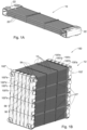
- a heat exchange module which is generally indicated at 10, for constructing a heat exchanger, for example as indicated at 12 in Fig. 1B .
- Each module 10 comprises a plurality of mats 20 connected at each end thereof to a manifold 22.
- the elements of the modules 10 may be made of any suitable material. According to some examples, they are made of a polymeric material, for example one which can withstand corrosive environments and/or working fluids flowing therethrough, e.g., in accordance with the conditions under which it is designed to operate. It will be appreciated that the module 10 may be provided such that all constituent elements thereof are made from the same material, or such that at least some are made from different materials.
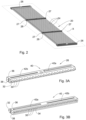
- each of the mats 20 comprises a plurality of planarly-arranged heat exchange tubes 24 defining a plane X, spanning between two headers 26, one at each end thereof.
- one or more support elements 28 may be provided transverse to the tubes 24, configured to maintain their positions relative to other tubes.
- each of the headers 26 comprises a plurality of through-going tube-apertures 30, each for receiving therein a tube 24, aligned linearly along an exchanger end 32 thereof, and which are in fluid communication with a header chamber 34, which is configured for being brought into fluid communication with one of the manifolds 22, as will be described below.
- Top and bottom surfaces 36, 38 of the header 26 are formed with positioning features 40, designed to cooperate with similar corresponding positioning features on a header placed thereon to facilitate a stacked arrangement thereof.
- the positioning arrangements 40 may be configured such that the positioning features 40 on both the top and bottom surfaces 36, 38 of the header 26 are designed to cooperate with the positioning features on either the top or bottom surface of an adjacent header.
- a positioning projection 42a may be provided spanning lengthwise on one side of the length of the top surface 36, and a correspondingly formed positioning socket 42b, configured to receive within a positioning projection, is provided spanning lengthwise on the other side of the top surface.
- a similar positioning projection and socket are formed on the bottom surface 38, on respective opposite sides (i.e., with the positioning socket of the bottom surface being formed on the same side along the length of the header 26 that the positioning projection 42a is formed on the top surface 36, and the positioning projection of the bottom face being formed on the same side along the length of the header that the positioning socket 42b is formed on the top surface).
- the positioning projections 42a of one will be aligned with the positioning sockets 42b of the other, irrespective of which of the top and bottom surfaces 36, 38 of each is facing upwardly.
- the headers 26 may be made of a moldable material, such as a polymer, e.g., a thermoplastic or thermoset. Accordingly, the header 26 may be formed directly on the tubes 24 connected thereto, e.g., by an overmolding process, thereby simplifying manufacture of the mat 20 by obviating the need to insert a large number of tubes 24 into their respective headers 26. In addition, by providing the header 26 which is overmolded on the tubes 24, the tubes do not need to be welded, either to the header or the manifold 22, mitigating the risk of ends of the tubes being deformed such that flow through them is restricted and/or prevented.
- a moldable material such as a polymer, e.g., a thermoplastic or thermoset. Accordingly, the header 26 may be formed directly on the tubes 24 connected thereto, e.g., by an overmolding process, thereby simplifying manufacture of the mat 20 by obviating the need to insert a large number of tubes 24 into their respective headers 26.
- each of the support elements 28 comprises a gripping portion 44 spanning between two flat end surfaces 27 and having a plurality of seats 46, each for receiving therein one of the tubes 24.
- Each seat 46 is defined between two upwardly-projecting dividers 48, each of which may terminate in an outwardly-flared head 50, which facilitates maintaining a respective tube 24 therein.
- the support elements 28 may be made from a material which provides sufficient flexibility to bias adjacent dividers 48 outwardly in order to facilitate introduction of a tube 24 into the seat 46 defined therebetween.
- the seats 46 may be evenly spaced along the length of the support element 28, giving rise to evenly sized gaps 25 between a majority of adjacent tubes 24 of each mat 20, with the exception of a small number (e.g., one or two) extreme seats 46a at one end, which is spaced from its adjacent seat by a different distance, for example a smaller distance, than are the other seats from one another, giving rise to auxiliary gaps 25a which are smaller than the other, evenly sized, gaps.
- a small number e.g., one or two
- the support elements 28 may further comprise a linking arrangement configured to facilitate rigid connection of each support element to one adjacent thereto, i.e., on an adjacent mat 20.
- This rigid connection may contribute to the mat's 20 stability, e.g., withstanding vibrations due to fluids rushing rapidly past the tubes 24.
- each of the linking arrangements may comprise upwardly-projecting linking tabs 52 and downwardly-facing linking slots 54, each configured to receive therein a linking tab, for example snappingly, thereby facilitating simple connection to an adjacent support element 28.
- the linking tabs 52 may face downwardly with the linking slots 54 facing upwardly, or be arranged in any other suitable manner, without departing from the scope of the presently disclosed subject matter, mutatis mutandis.
- the linking tabs and slots 52, 54 are spaced such that when one of the support elements 28 is disposed above the other, each of the linking tabs of one of the support elements is aligned with a corresponding linking slot of the other.
- the linking tabs and slots 52, 54 may be spaced such that each of the linking tabs of one of the support elements is aligned with a corresponding linking slot of the other only when they are reversed with respect to one another, i.e., the extreme seats 46a thereof are on opposite sides along their lengths, as illustrated in Fig. 4B . Accordingly, and owing to the different spacing of the extreme seats 46a from that adjacent to it, the tubes 24 of adjacent mats 20 are offset with respect to one another, such that each of the gaps 25, 25a is disposed such that it overlaps with the projection, which lies in a direction perpendicular to the planes X defined by the mats 20, of a tube of an adjacent mat.
- any path through the tubes 24 of the module which is perpendicular to the mats 20 necessarily impinges on a tube 24, even if it passes through a gap 25, 25a of a mat in front thereof.
- Such a "staggered” arrangement may facilitate airflow through the module 10 which transfers heat between the tubes and the environment more efficiently.
- the support elements 28 may be further used to facilitate construction of the heat exchanger 12. As seen in Fig. 1B , several of the modules may be attached such that they are stacked.
- the support elements 28 may facilitate maintaining the tubes 24 is substantially horizontal positions, e.g., preventing them from assuming a catenary or similar shape under their own weights.
- the flat end surface 27 thereof may lie on each other, wherein vertically-stacked support elements 28 form a support structure, facilitating bearing the loads of all tubes 24, e.g., by the floor.
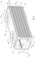
- each of the manifolds 22 comprises a housing 58 defining therewithin a fluid chamber 60.
- a bottom surface 62 of the housing 58 is formed with a header-interface 64, configured for bringing the tubes 24 into fluid communication with the fluid chamber 60.
- the header-interface 64 comprises a plurality of parallely-arranged rows of through-going apertures 66.
- the apertures 66 may be arranged to conform to the staggered arrangement of tubes 24, for example as illustrated in Fig. 4 .
- a channel 68 may be formed along each row, thereby insetting the apertures 66 below the surface of the header-interface 64.
- the channels 68 may be configured to lie in registration with the header chamber 34 of a corresponding header 26 when assembled to the manifold 22.
- the header-interface 64 may further comprise grooves 70 formed between the rows of apertures 66 defining therebetween a plurality of bases 72 at the surface of the header-interface, each for contacting a header 26 when the mat 20 is assembled, for example for being welded thereto.
- Side surfaces 74 of the housing 58 are each formed with one or more selectively sealable (i.e., configured to facilitate it to be sealed, thereby preventing flow of fluid therethrough, selectively) side openings 76 for attachment to an adjacent manifold, each defining a lateral flow path P lat therethrough.
- the lateral flow paths P lat are each substantially perpendicular to the planes defined by the tubes 24.
- a raised side-lip 78 may be formed about each side opening 76, constituting a welding surface for facilitating a sealing connection to another element, such as a cap, inlet/outlet or a corresponding side-lip of an adjacent manifold (thereby bringing the two manifolds into fluid communication with each other via the facing side openings), as described below.
- outer surfaces 78a of the side-lips 78 may be configured to substantially fully contact corresponding side-lips of an adjacent manifold 22 when two manifolds are disposed adjacently to another with the side surface 74 of one facing a side surface of the other, e.g., the outer surface of each side-lip may be flat and substantially parallel to a plane defined by the tubes 24 of one of the mats 20.
- Ends 80 of the housing 58 are each formed with a selectively sealable end opening 82, for attachment to an adjacent manifold, and defining a longitudinal flow path P lon therebetween.
- the longitudinal flow path P lon is substantially perpendicular to the tubes 24 and the lateral flow path P lat , and parallel to the planes defined thereby.
- a raised end-lip 84 may be formed around each end opening 82, constituting a welding surface for sealing connection to another element, such as a cap, inlet/outlet or a corresponding end-lip of an adjacent manifold (thereby bringing the two manifolds into fluid communication with each other via the facing end openings), as described below.
- an outer surface 84a of each end-lip 84 may be configured to substantially fully contact a corresponding end-lip of an adjacent manifold 22 when two manifolds are disposed adjacently to another with the end 80 of one facing the end of the other, e.g., the outer surface of each end-lip may be flat and substantially perpendicular to an axis traversing longitudinally through the fluid chamber 60.
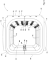
- an inner surface of the manifold 22 may be provided with a division arrangement of the manifold, comprising a pair of longitudinally extending slots 86, for example each defined between a pair of longitudinal projections 88.
- the slots 86 face one another, and are disposed between the side surfaces 74 of the housing 58, i.e., such that one of the slots is formed on an inner surface of the header-interface 64.
- the slots 86 may be formed halfway between the side surfaces 74, such that as many rows of apertures 66 (and thereby headers 26 attached to the manifold 22) are above them as are below them.
- the slots 86 are configured for receiving therein a partition (not illustrated in Fig.
- fluid isolation within the fluid chamber 60 is only considered within the chamber itself, e.g., it does not consider that fluid may cross the partition by exiting the chamber via an opening 76, 82 or via the header-interface 64.
- fluid access to the module 10 may be controlled by selectively blocking the side and end openings 76, 82 of the manifolds 22, and/or by facilitating access thereto.
- Side and end caps 90, 92 may be provided to seal the side and end openings 76, 82, respectively, for example being welded to the side- and end-lips 78, 84.
- Nipples 94 may be provided, for example to be connected lying in registration with side and/or end openings 76, 82, facilitating bringing the fluid chamber 60 of one or manifolds into fluid communication with an external fluid pipe.
- a nipple 94 may be provided on areas of the housing 58 not formed with an opening, for example by a user cutting an opening in a top surface 56 (as indicated in Fig. 5 ) of the housing as necessary.
- modules 10 may be assembled together to form the heat exchanger 12.
- modules 10 are arranged with the manifolds on each side thereof stacked together, such that side surfaces 74 thereof face each other, with side-lips 78 thereof lying in registration with those of adjacent modules, i.e., outer surfaces 78a of the side-lips contacting one another, defining side junctions 100 therebetween.
- reference numeral may be used to refer collectively to all reference numerals which include the same number followed by a trailing letter and/or prime, e.g., 100 may be used to refer collectively to 100'a, 100'b, 100"a, 100"b, etc.
- 100' may be used to refer collectively to 100'a, 100'b, etc.
- 100a may be used to refer collectively to 100'a and 100"a.
- Two or more modules 10 so stacked constitute a lateral subassembly 150 of the heat exchanger, spanning between first and second ends 102', 102" defined by the manifolds 22.
- the prime notation is used to refer to corresponding side junctions 100 formed between opposite ends 102 of the same manifolds, i.e., side junction 100a is formed between first ends 102' of the same pair of adjacent manifolds 22 between the second ends 102" of which side junction 100'a is formed.
- the lateral subassembly 150 may be configured to regulate fluid flow therethrough.
- alternating side junctions 100' on the first end 102' may be connected to one another, bringing the fluid chambers 60 of pairs of manifolds 22 in fluid communication with one another, with the other side junctions 100' of the first end 102' being sealed, e.g., with side caps 90, to prevent fluid flow between adjacent manifolds therethrough.
- alternating side junctions 100" on the second end 102 are connected to one another, bringing the fluid chambers 60 of pairs of manifolds 22 in fluid communication with one another, with the other side junctions 100" of the second end 102" being sealed, e.g., with side caps 90, to prevent fluid flow between adjacent manifolds therethrough.
- fluid within the lateral subassembly 150 flows through each mat 20 in succession, with the direction of fluid flow being reversed between adjacent modules, as indicated by arrows.
- Nipples 94 may be provided as necessary at the entrance and exit of the fluid flow path so defined.
- all of the side junctions 100' of the first end 102' are left unsealed, and all of the side junctions 100" of the second end 102" are sealed.
- partitions 104 are provided in the manifolds 22 of the first end 102', thereby fluidly isolating some of the headers 26 of each module 10 from the others within the manifold 22. Accordingly, fluid within the lateral subassembly 150 flows through each mat 20 in succession in both direction, reversing direction one time therewithin.
- the manifolds 22 may be configured to receive more than one partitions, thereby allowing reversing of fluid flow more than once within each Nipples 94 may be provided as necessary at the entrance and exit of the fluid flow path so defined.
- the heat exchanger 12 may comprise a single module 10, a single lateral subassembly 150, one or more modules connected only by end openings 82 thereof, several lateral subassemblies connected by end openings thereof, any of the above or other combinations modified by connecting adjacent manifolds 22 via holes cut by a user in top surfaces 56 thereof (e.g., as illustrated in Fig. 1B ), or any other suitable arrangement of modules, without departing from the scope of the presently disclosed subject matter, mutatis mutandis.
- the heat exchanger 12 may be provided with flow blockers 110 between adjacent modules 10, configured to fill the space therebetween, thereby ensuring that fluid transverse to the heat exchanger 12 passes across the tubes 24, where heat exchange primarily takes places.
- the flow blockers 110 may be L-shaped, with positioning apertures 112 formed therein.
- the modules 10 are formed with pins 114, for example provided on the manifolds 22, for mating with the positioning apertures 112.
- the positioning apertures 112 may have a diameter similar to that of the pin, and a wider diameter on an upper portion thereof.
- the pin 114 can be melted to fill the void within the upper diameter of the positioning apertures 112, thereby filling it and locking the flow blocker 110 in place.
- the pin 114 may be taller than the height of the positioning apertures 112, thereby providing material to fill the upper diameter when melted.
Landscapes
- Engineering & Computer Science (AREA)
- Physics & Mathematics (AREA)
- Thermal Sciences (AREA)
- Mechanical Engineering (AREA)
- General Engineering & Computer Science (AREA)
- Heat-Exchange Devices With Radiators And Conduit Assemblies (AREA)
Description
- This invention relates to heat exchangers. In particular, it relates to heat exchangers which may be assembled modularly.
- Heat exchangers are commonly used in diverse application to expel and/or capture heat. They may include a plurality of pipes or tubes which contain a heat exchange fluid flowing therethrough, and which is exposed to an environment of a higher or lower temperature. As the heat exchange fluid flows through the tubes, the temperature thereof is brought closer to that of the environment, thereby cooling or heating it, as per the required design.
-
US 2010/206532 A1 discloses a heat exchanger in which a separator plate separates a header into manifold chambers each connected to a plurality of fluid channels.EP 0683373 A1 discloses a heat exchanger having heat transfer tubes extending between upper and lower chambers formed by partitions.DE 102012011926 A1 discloses a heat exchanger comprising a multi-chamber panel formed of plastic and having multiple chambers in a longitudinal direction. -
WO2011084613A2 relates to a modular heat exchanger assembly includes a plurality of heat exchanger sections arranged in a stacked configuration, wherein each heat exchanger section includes a plurality of conduits, and wherein each heat exchanger section includes a first plate and a second plate. Each plate has a plurality of conduit portions that are attached to the conduit portions of the other plate to form the conduits. A first fluid flow path extends through the conduits. The conduits within each heat exchanger section are separated from one another and a second fluid flow path extends between the conduits within the assembly and through the assembly and which is separated from the first fluid flow path. - The present invention provides a module according to claim 1. The dependent claims set out particular embodiments of the invention.
- According to a still further aspect of the presently disclosed subject matter, there is provided a heat exchanger comprising one or more modules as described above.
- In order to understand the invention and to see how it may be carried out in practice, embodiments will now be described, by way of non-limiting examples only, with reference to the accompanying drawings, in which:
-
Fig. 1A is a perspective view of a heat exchange module, according to the presently disclosed subject matter; -
Fig. 1B is a perspective view of a heat exchanger made of modules as illustrated inFig. 1A ; -
Fig. 2 is a mat of the module illustrated inFig. 1A ; -
Figs. 3A and 3B are, respectively, front and rear respective views of a header of the mat illustrated inFig. 2 ; -
Fig. 4A is a front view of a support element of the mat illustrated inFig. 2 ; -
Fig. 4B is a front view of several of the support elements illustrated inFig. 4A connected to each other; -
Fig. 5 is a perspective view of a manifold of the module illustrated inFig. 1A ; -
Fig. 6 is an end view of the manifold illustrated inFig. 5 ; -
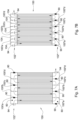
Figs. 7A and 7B are schematic illustrations of assembly of several of the mats illustrated inFig. 1A ; -
Figs. 8A and 8B are close-up views of, respectively, the module illustrated inFig. 1A and the heat exchanger illustrated inFig. 1B , showing a flow blocker; and -
Fig. 8C is a cross-sectional close up view of the flow blocker illustrated inFigs. 8A and 8B mounted on the module, before being secured thereto. - As illustrated in
Fig. 1A , there is provided a heat exchange module, which is generally indicated at 10, for constructing a heat exchanger, for example as indicated at 12 inFig. 1B . Eachmodule 10 comprises a plurality ofmats 20 connected at each end thereof to amanifold 22. The elements of themodules 10 may be made of any suitable material. According to some examples, they are made of a polymeric material, for example one which can withstand corrosive environments and/or working fluids flowing therethrough, e.g., in accordance with the conditions under which it is designed to operate. It will be appreciated that themodule 10 may be provided such that all constituent elements thereof are made from the same material, or such that at least some are made from different materials. - As better seen in
Fig. 2 , each of themats 20 comprises a plurality of planarly-arrangedheat exchange tubes 24 defining a plane X, spanning between twoheaders 26, one at each end thereof. In addition, one ormore support elements 28 may be provided transverse to thetubes 24, configured to maintain their positions relative to other tubes. - As seen in
Figs. 3A and 3B , each of theheaders 26 comprises a plurality of through-going tube-apertures 30, each for receiving therein atube 24, aligned linearly along anexchanger end 32 thereof, and which are in fluid communication with aheader chamber 34, which is configured for being brought into fluid communication with one of themanifolds 22, as will be described below. - Top and
bottom surfaces header 26 are formed withpositioning features 40, designed to cooperate with similar corresponding positioning features on a header placed thereon to facilitate a stacked arrangement thereof. Thepositioning arrangements 40 may be configured such that the positioning features 40 on both the top andbottom surfaces header 26 are designed to cooperate with the positioning features on either the top or bottom surface of an adjacent header. - For example, a
positioning projection 42a may be provided spanning lengthwise on one side of the length of thetop surface 36, and a correspondingly formedpositioning socket 42b, configured to receive within a positioning projection, is provided spanning lengthwise on the other side of the top surface. A similar positioning projection and socket (not illustrated) are formed on thebottom surface 38, on respective opposite sides (i.e., with the positioning socket of the bottom surface being formed on the same side along the length of theheader 26 that thepositioning projection 42a is formed on thetop surface 36, and the positioning projection of the bottom face being formed on the same side along the length of the header that thepositioning socket 42b is formed on the top surface). Accordingly, when twoheaders 26 are stacked one atop the other with the exchanger ends 32 thereof parallel to one another and facing the same direction, thepositioning projections 42a of one will be aligned with thepositioning sockets 42b of the other, irrespective of which of the top andbottom surfaces - The
headers 26 may be made of a moldable material, such as a polymer, e.g., a thermoplastic or thermoset. Accordingly, theheader 26 may be formed directly on thetubes 24 connected thereto, e.g., by an overmolding process, thereby simplifying manufacture of themat 20 by obviating the need to insert a large number oftubes 24 into theirrespective headers 26. In addition, by providing theheader 26 which is overmolded on thetubes 24, the tubes do not need to be welded, either to the header or the manifold 22, mitigating the risk of ends of the tubes being deformed such that flow through them is restricted and/or prevented. - As illustrated in
Fig. 4A , each of thesupport elements 28 comprises a grippingportion 44 spanning between two flat end surfaces 27 and having a plurality of seats 46, each for receiving therein one of thetubes 24. Each seat 46 is defined between two upwardly-projectingdividers 48, each of which may terminate in an outwardly-flaredhead 50, which facilitates maintaining arespective tube 24 therein. Thesupport elements 28 may be made from a material which provides sufficient flexibility to biasadjacent dividers 48 outwardly in order to facilitate introduction of atube 24 into the seat 46 defined therebetween. - The seats 46 may be evenly spaced along the length of the
support element 28, giving rise to evenlysized gaps 25 between a majority ofadjacent tubes 24 of eachmat 20, with the exception of a small number (e.g., one or two)extreme seats 46a at one end, which is spaced from its adjacent seat by a different distance, for example a smaller distance, than are the other seats from one another, giving rise toauxiliary gaps 25a which are smaller than the other, evenly sized, gaps. - The
support elements 28 may further comprise a linking arrangement configured to facilitate rigid connection of each support element to one adjacent thereto, i.e., on anadjacent mat 20. This rigid connection may contribute to the mat's 20 stability, e.g., withstanding vibrations due to fluids rushing rapidly past thetubes 24. - According to some examples, each of the linking arrangements may comprise upwardly-projecting
linking tabs 52 and downwardly-facinglinking slots 54, each configured to receive therein a linking tab, for example snappingly, thereby facilitating simple connection to anadjacent support element 28. It will be appreciated that the linkingtabs 52 may face downwardly with the linkingslots 54 facing upwardly, or be arranged in any other suitable manner, without departing from the scope of the presently disclosed subject matter, mutatis mutandis. The linking tabs andslots support elements 28 is disposed above the other, each of the linking tabs of one of the support elements is aligned with a corresponding linking slot of the other. - According to some examples, the linking tabs and
slots extreme seats 46a thereof are on opposite sides along their lengths, as illustrated inFig. 4B . Accordingly, and owing to the different spacing of theextreme seats 46a from that adjacent to it, thetubes 24 ofadjacent mats 20 are offset with respect to one another, such that each of thegaps mats 20, of a tube of an adjacent mat. Accordingly, any path through thetubes 24 of the module which is perpendicular to themats 20 necessarily impinges on atube 24, even if it passes through agap module 10 which transfers heat between the tubes and the environment more efficiently. - The
support elements 28 may be further used to facilitate construction of theheat exchanger 12. As seen inFig. 1B , several of the modules may be attached such that they are stacked. Thesupport elements 28 may facilitate maintaining thetubes 24 is substantially horizontal positions, e.g., preventing them from assuming a catenary or similar shape under their own weights. In addition, theflat end surface 27 thereof may lie on each other, wherein vertically-stackedsupport elements 28 form a support structure, facilitating bearing the loads of alltubes 24, e.g., by the floor. - As illustrated in
Fig 5 , each of themanifolds 22 comprises ahousing 58 defining therewithin afluid chamber 60. Abottom surface 62 of thehousing 58 is formed with a header-interface 64, configured for bringing thetubes 24 into fluid communication with thefluid chamber 60. The header-interface 64 comprises a plurality of parallely-arranged rows of through-goingapertures 66. Theapertures 66 may be arranged to conform to the staggered arrangement oftubes 24, for example as illustrated inFig. 4 . In addition, a channel 68 may be formed along each row, thereby insetting theapertures 66 below the surface of the header-interface 64. The channels 68 may be configured to lie in registration with theheader chamber 34 of acorresponding header 26 when assembled to themanifold 22. The header-interface 64 may further comprisegrooves 70 formed between the rows ofapertures 66 defining therebetween a plurality ofbases 72 at the surface of the header-interface, each for contacting aheader 26 when themat 20 is assembled, for example for being welded thereto. - Side surfaces 74 of the
housing 58 are each formed with one or more selectively sealable (i.e., configured to facilitate it to be sealed, thereby preventing flow of fluid therethrough, selectively)side openings 76 for attachment to an adjacent manifold, each defining a lateral flow path Plat therethrough. The lateral flow paths Plat are each substantially perpendicular to the planes defined by thetubes 24. A raised side-lip 78 may be formed about eachside opening 76, constituting a welding surface for facilitating a sealing connection to another element, such as a cap, inlet/outlet or a corresponding side-lip of an adjacent manifold (thereby bringing the two manifolds into fluid communication with each other via the facing side openings), as described below. Accordingly,outer surfaces 78a of the side-lips 78 may be configured to substantially fully contact corresponding side-lips of anadjacent manifold 22 when two manifolds are disposed adjacently to another with theside surface 74 of one facing a side surface of the other, e.g., the outer surface of each side-lip may be flat and substantially parallel to a plane defined by thetubes 24 of one of themats 20. - Ends 80 of the
housing 58 are each formed with a selectivelysealable end opening 82, for attachment to an adjacent manifold, and defining a longitudinal flow path Plon therebetween. The longitudinal flow path Plon is substantially perpendicular to thetubes 24 and the lateral flow path Plat, and parallel to the planes defined thereby. A raised end-lip 84 may be formed around each end opening 82, constituting a welding surface for sealing connection to another element, such as a cap, inlet/outlet or a corresponding end-lip of an adjacent manifold (thereby bringing the two manifolds into fluid communication with each other via the facing end openings), as described below. Accordingly, anouter surface 84a of each end-lip 84 may be configured to substantially fully contact a corresponding end-lip of anadjacent manifold 22 when two manifolds are disposed adjacently to another with theend 80 of one facing the end of the other, e.g., the outer surface of each end-lip may be flat and substantially perpendicular to an axis traversing longitudinally through thefluid chamber 60. - As best seen in
Fig. 6 , an inner surface of the manifold 22 may be provided with a division arrangement of the manifold, comprising a pair of longitudinally extendingslots 86, for example each defined between a pair oflongitudinal projections 88. Theslots 86 face one another, and are disposed between the side surfaces 74 of thehousing 58, i.e., such that one of the slots is formed on an inner surface of the header-interface 64. Theslots 86 may be formed halfway between the side surfaces 74, such that as many rows of apertures 66 (and therebyheaders 26 attached to the manifold 22) are above them as are below them. Theslots 86 are configured for receiving therein a partition (not illustrated inFig. 6 ), thereby fluidly isolating two halves of thefluid chamber 60 defined thereby, and thus theheaders 26 on either side thereof, from one another, for example to control fluid flow through themodule 10, as will be described below. It will be appreciated that fluid isolation within thefluid chamber 60 is only considered within the chamber itself, e.g., it does not consider that fluid may cross the partition by exiting the chamber via anopening interface 64. - Reverting to
Fig. 1B , fluid access to themodule 10 may be controlled by selectively blocking the side and endopenings manifolds 22, and/or by facilitating access thereto. Side andend caps 90, 92 may be provided to seal the side and endopenings lips Nipples 94 may be provided, for example to be connected lying in registration with side and/or endopenings fluid chamber 60 of one or manifolds into fluid communication with an external fluid pipe. As illustrated, anipple 94 may be provided on areas of thehousing 58 not formed with an opening, for example by a user cutting an opening in a top surface 56 (as indicated inFig. 5 ) of the housing as necessary. -
Several modules 10 may be assembled together to form theheat exchanger 12. According to some examples,modules 10 are arranged with the manifolds on each side thereof stacked together, such that side surfaces 74 thereof face each other, with side-lips 78 thereof lying in registration with those of adjacent modules, i.e.,outer surfaces 78a of the side-lips contacting one another, definingside junctions 100 therebetween. (Herein, reference numeral may be used to refer collectively to all reference numerals which include the same number followed by a trailing letter and/or prime, e.g., 100 may be used to refer collectively to 100'a, 100'b, 100"a, 100"b, etc. Similarly, 100' may be used to refer collectively to 100'a, 100'b, etc., and 100a may be used to refer collectively to 100'a and 100"a.) Two ormore modules 10 so stacked constitute alateral subassembly 150 of the heat exchanger, spanning between first and second ends 102', 102" defined by themanifolds 22. In the present disclosure, the prime notation is used to refer tocorresponding side junctions 100 formed between opposite ends 102 of the same manifolds, i.e., side junction 100a is formed between first ends 102' of the same pair ofadjacent manifolds 22 between the second ends 102" of which side junction 100'a is formed. - The
lateral subassembly 150 may be configured to regulate fluid flow therethrough. According to some examples, as illustrated schematically inFig. 7A , alternating side junctions 100' on the first end 102' may be connected to one another, bringing thefluid chambers 60 of pairs ofmanifolds 22 in fluid communication with one another, with the other side junctions 100' of the first end 102' being sealed, e.g., with side caps 90, to prevent fluid flow between adjacent manifolds therethrough. Similarly, alternatingside junctions 100" on thesecond end 102", each of which corresponds to a sealed side junction 100' of the first end 102', are connected to one another, bringing thefluid chambers 60 of pairs ofmanifolds 22 in fluid communication with one another, with theother side junctions 100" of thesecond end 102" being sealed, e.g., with side caps 90, to prevent fluid flow between adjacent manifolds therethrough. Accordingly, fluid within thelateral subassembly 150 flows through eachmat 20 in succession, with the direction of fluid flow being reversed between adjacent modules, as indicated by arrows.Nipples 94 may be provided as necessary at the entrance and exit of the fluid flow path so defined. - According to other examples, all of the side junctions 100' of the first end 102' are left unsealed, and all of the
side junctions 100" of thesecond end 102" are sealed. In addition,partitions 104 are provided in themanifolds 22 of the first end 102', thereby fluidly isolating some of theheaders 26 of eachmodule 10 from the others within themanifold 22. Accordingly, fluid within thelateral subassembly 150 flows through eachmat 20 in succession in both direction, reversing direction one time therewithin. It will be appreciated that themanifolds 22 may be configured to receive more than one partitions, thereby allowing reversing of fluid flow more than once within eachNipples 94 may be provided as necessary at the entrance and exit of the fluid flow path so defined. - It will be appreciated that the
heat exchanger 12 may comprise asingle module 10, a singlelateral subassembly 150, one or more modules connected only byend openings 82 thereof, several lateral subassemblies connected by end openings thereof, any of the above or other combinations modified by connectingadjacent manifolds 22 via holes cut by a user intop surfaces 56 thereof (e.g., as illustrated inFig. 1B ), or any other suitable arrangement of modules, without departing from the scope of the presently disclosed subject matter, mutatis mutandis. - As illustrated in
Figs. 8A and 8B , theheat exchanger 12 may be provided withflow blockers 110 betweenadjacent modules 10, configured to fill the space therebetween, thereby ensuring that fluid transverse to theheat exchanger 12 passes across thetubes 24, where heat exchange primarily takes places. Theflow blockers 110 may be L-shaped, withpositioning apertures 112 formed therein. Themodules 10 are formed withpins 114, for example provided on themanifolds 22, for mating with thepositioning apertures 112. As seen inFig. 8C , thepositioning apertures 112 may have a diameter similar to that of the pin, and a wider diameter on an upper portion thereof. Accordingly, thepin 114 can be melted to fill the void within the upper diameter of thepositioning apertures 112, thereby filling it and locking theflow blocker 110 in place. Thepin 114 may be taller than the height of thepositioning apertures 112, thereby providing material to fill the upper diameter when melted. - Those skilled in the art to which this invention pertains will readily appreciate that numerous changes, variations and modifications can be made without departing from the scope of the invention as defined by the claims.
Claims (6)
- A module (10) for constructing therefrom a heat exchanger, the module comprising:• two manifolds (22); and• a plurality of parallely arranged mats (20) spanning between the manifolds (22), each mat comprising a plurality of heat exchange tubes (24) arranged so as to define a plane (X), the plurality of tubes (24) comprising one extreme tube at each end of the plane (X), said heat exchange tubes (24) being in fluid communication with the manifolds (22) and spanning therebetween,wherein at least one of the manifolds (22) comprises a division arrangement (86) configured to facilitate selectively fluidly isolating one or more of said mats (20) from the tubes (24) of the other mats (20);the tubes (24) in each mat (20) being spaced from one another giving rise to gaps (25) therebetween; anda majority of the gaps in each mat (20) are of the same size,characterised in that eachof said mats further comprising one or more auxiliary gaps (25a) of a different size, wherein said auxiliary gaps (25a) are formed adjacent to one of said extreme tubes, and wherein said mats (20) are arranged such that the one or more auxiliary gaps (25a) of adjacent mats are on alternate sides thereof from one another, such that the extreme tubes of adjacent mats are not offset with respect to each other, and the remaining tubes of adjacent mats are offset with respect to each other.
- The module according to claim 1, wherein said auxiliary gaps (25a) are smaller than said majority of the gaps (25).
- The module according to claim 2, wherein each of said mats (20) comprises two adjacent auxiliary gaps (25a).
- The module according to any one of the preceding claims, each mat (20) comprising one or more support elements (28) disposed coplanar therewith and transverse to said tubes (24), said support elements (28) being configured to grip each of said tubes (24) and maintain its position, each of said support elements (28) being further configured to be rigidly connected to a support element (28) of an adjacent mat (20).
- The module according to claim 4, said support elements (28) comprising a linking arrangement (52,54) configured to cooperate with the linking arrangement (52,54) of an adjacent support element (28) to facilitate the rigid connection.
- A heat exchanger comprising one or more modules (10) according to any one of the preceding claims.
Applications Claiming Priority (2)
| Application Number | Priority Date | Filing Date | Title |
|---|---|---|---|
| IL248304A IL248304B (en) | 2016-10-10 | 2016-10-10 | Heat exchanger and module thereof |
| PCT/IL2017/051120 WO2018069919A1 (en) | 2016-10-10 | 2017-10-03 | Heat exchanger and module thereof |
Publications (4)
| Publication Number | Publication Date |
|---|---|
| EP3523588A1 EP3523588A1 (en) | 2019-08-14 |
| EP3523588A4 EP3523588A4 (en) | 2020-02-26 |
| EP3523588B1 true EP3523588B1 (en) | 2023-12-06 |
| EP3523588C0 EP3523588C0 (en) | 2023-12-06 |
Family
ID=57907549
Family Applications (1)
| Application Number | Title | Priority Date | Filing Date |
|---|---|---|---|
| EP17860446.8A Active EP3523588B1 (en) | 2016-10-10 | 2017-10-03 | Heat exchanger and module thereof |
Country Status (6)
| Country | Link |
|---|---|
| US (1) | US11118840B2 (en) |
| EP (1) | EP3523588B1 (en) |
| JP (1) | JP7056961B2 (en) |
| CN (2) | CN109804214A (en) |
| IL (1) | IL248304B (en) |
| WO (1) | WO2018069919A1 (en) |
Families Citing this family (6)
| Publication number | Priority date | Publication date | Assignee | Title |
|---|---|---|---|---|
| CN109186006A (en) * | 2018-10-19 | 2019-01-11 | 际高科技有限公司 | A kind of solar energy actified solution formula evaporation water cooler |
| CN109186005A (en) * | 2018-10-19 | 2019-01-11 | 际高科技有限公司 | A kind of solution-type evaporation water cooler |
| CN109186004A (en) * | 2018-10-19 | 2019-01-11 | 际高科技有限公司 | A kind of small modular solution humidifying unit |
| JP7228841B2 (en) * | 2019-12-06 | 2023-02-27 | 有限会社エクサ | Heat exchanger |
| CN112781409B (en) * | 2021-01-10 | 2021-12-03 | 北京红岸水滴科技发展有限公司 | Heat exchanger and dish-washing machine |
| EP4414650B8 (en) * | 2023-02-13 | 2025-09-10 | Zhejiang Youxu Technology Co., Ltd | Heat exchange system with flexible heat exchanger |
Citations (2)
| Publication number | Priority date | Publication date | Assignee | Title |
|---|---|---|---|---|
| AU5362079A (en) * | 1978-12-15 | 1980-09-04 | John Bernard Morrissey | Supports for heat exchanger tubes |
| WO2011084613A2 (en) * | 2009-12-17 | 2011-07-14 | Carrier Corporation | Modular heat exchanger assembly |
Family Cites Families (23)
| Publication number | Priority date | Publication date | Assignee | Title |
|---|---|---|---|---|
| FR499085A (en) | 1919-05-06 | 1920-01-30 | Albert Strack | Improvements to devices used to heat or cool air |
| CH129087A (en) | 1927-10-25 | 1928-12-01 | Ventilator A G | Heat exchange element. |
| JPS618779U (en) * | 1984-06-21 | 1986-01-20 | 石川島播磨重工業株式会社 | Heat exchanger |
| US4619315A (en) * | 1985-04-10 | 1986-10-28 | Combustion Engineering, Inc. | Fluidized bed boiler in-bed tube support bracket |
| GB8711428D0 (en) * | 1987-05-14 | 1987-06-17 | Du Pont Canada | Comfort heat exchanger |
| IL109269A (en) * | 1994-04-10 | 1996-10-31 | Magen Plastic | Heat exchanger |
| JPH07305990A (en) | 1994-05-16 | 1995-11-21 | Sanden Corp | Multitubular type heat exchanger |
| JPH08178471A (en) * | 1994-12-27 | 1996-07-12 | Daikin Ind Ltd | Absorption refrigerator heat exchanger and method of manufacturing the same |
| DE19719252C2 (en) * | 1997-05-07 | 2002-10-31 | Valeo Klimatech Gmbh & Co Kg | Double-flow and single-row brazed flat tube evaporator for a motor vehicle air conditioning system |
| JP2000088297A (en) * | 1998-09-17 | 2000-03-31 | Hitachi Ltd | Ice storage type air conditioner and ice storage tank |
| KR100590658B1 (en) * | 2004-04-28 | 2006-06-19 | 모딘코리아 유한회사 | Header pipe of car evaporator |
| FR2912209B1 (en) * | 2007-02-06 | 2013-08-23 | Valeo Systemes Thermiques | MULTI-CIRCUIT EXCHANGER |
| US8851158B2 (en) | 2009-02-17 | 2014-10-07 | Hamilton Sundstrand Corporation | Multi-chamber heat exchanger header and method of making |
| DE102009013280A1 (en) | 2009-03-14 | 2010-09-16 | Modine Manufacturing Co., Racine | Heat exchanger e.g. condenser, for use in e.g. carbon dioxide air conditioning system, has extension attachments tapered in cross section, where tapered section of extension attachments extends through openings in bottom of base part |
| GB2472782A (en) | 2009-08-17 | 2011-02-23 | Tube Tech Int Ltd | Cleaning of finned heat exchangers where the cleaning fluid flows from the interior to the exterior |
| US8464782B2 (en) * | 2009-10-20 | 2013-06-18 | Delphi Technologies, Inc. | Manifold fluid communication plate |
| AU2010334448B2 (en) * | 2009-12-21 | 2015-11-19 | Magen Eco-Energy (A.C.S.) Ltd. | Heat exchanger and a manifold for use therein |
| JP5559088B2 (en) | 2010-05-18 | 2014-07-23 | 株式会社ワイ・ジェー・エス. | Heat exchanger |
| DE102012011926A1 (en) | 2012-06-15 | 2013-12-19 | BeKa Heiz- und Kühlmatten GmbH | Heat exchanger coil for use in controlling temperature of buildings, has connection profiles that include flow connector which is sealingly arranged between chambers on multi-chamber profile |
| KR20140006681A (en) * | 2012-07-06 | 2014-01-16 | 삼성전자주식회사 | Heat exchanger and method for the same |
| KR20150109130A (en) * | 2014-03-19 | 2015-10-01 | 삼성전자주식회사 | Heat exchanger and manufacturing method for the same |
| US10126065B2 (en) * | 2015-06-17 | 2018-11-13 | Mahle International Gmbh | Heat exchanger assembly having a refrigerant distribution control using selective tube port closures |
| IL243897B (en) * | 2016-02-01 | 2021-01-31 | Magen Eco Energy A C S Ltd | Solar water heating system and its panel |
-
2016
- 2016-10-10 IL IL248304A patent/IL248304B/en unknown
-
2017
- 2017-10-03 JP JP2019515861A patent/JP7056961B2/en active Active
- 2017-10-03 WO PCT/IL2017/051120 patent/WO2018069919A1/en not_active Ceased
- 2017-10-03 EP EP17860446.8A patent/EP3523588B1/en active Active
- 2017-10-03 US US16/340,803 patent/US11118840B2/en active Active
- 2017-10-03 CN CN201780062519.4A patent/CN109804214A/en active Pending
- 2017-10-03 CN CN202311376691.0A patent/CN117516223A/en active Pending
Patent Citations (2)
| Publication number | Priority date | Publication date | Assignee | Title |
|---|---|---|---|---|
| AU5362079A (en) * | 1978-12-15 | 1980-09-04 | John Bernard Morrissey | Supports for heat exchanger tubes |
| WO2011084613A2 (en) * | 2009-12-17 | 2011-07-14 | Carrier Corporation | Modular heat exchanger assembly |
Also Published As
| Publication number | Publication date |
|---|---|
| EP3523588A4 (en) | 2020-02-26 |
| JP7056961B2 (en) | 2022-04-19 |
| CN109804214A (en) | 2019-05-24 |
| CN117516223A (en) | 2024-02-06 |
| EP3523588A1 (en) | 2019-08-14 |
| US11118840B2 (en) | 2021-09-14 |
| WO2018069919A1 (en) | 2018-04-19 |
| US20190257587A1 (en) | 2019-08-22 |
| JP2019529859A (en) | 2019-10-17 |
| IL248304A0 (en) | 2017-01-31 |
| EP3523588C0 (en) | 2023-12-06 |
| IL248304B (en) | 2021-07-29 |
Similar Documents
| Publication | Publication Date | Title |
|---|---|---|
| US11118840B2 (en) | Heat exchanger and module thereof | |
| US11843102B2 (en) | Counter-flow heat exchanger for battery thermal management applications | |
| US11976894B2 (en) | High-performance heat exchanger with calibrated bypass | |
| EP4235915B1 (en) | Counter-flow heat exchanger for battery thermal management applications | |
| CN110199430B (en) | Counterflow heat exchanger with in-line fittings | |
| US10006722B2 (en) | Structural support element in heat exchangers | |
| EP3884520B1 (en) | Cooling system | |
| KR102592704B1 (en) | heat exchanger for cooling electric element | |
| JP2010505081A (en) | Multi-flow heat exchanger | |
| GB2303910A (en) | Heat exchanger with a stacked plate structure | |
| US20120267084A1 (en) | Double-wall vented brazed heat exchanger | |
| CN105793662A (en) | Heat exchanger with improved flow | |
| CN107429977A (en) | Flexible construction of heat exchangers for heating and/or cooling liquids | |
| KR20200121102A (en) | Micro channel heat exchanger and heat exchanging device comprising it | |
| US8794301B2 (en) | Flow distributor assembly and a cooling unit with a flow distributor assembly | |
| EP2485005A2 (en) | Heat exchanger assembly with fin locating structure | |
| EP2223741A1 (en) | Micro fluidic system, including a stack of process modules and heat exchange modules | |
| US20160001256A1 (en) | Catalytic reactor and method for manufacturing catalytic reactor | |
| CN111536814B (en) | Liquid heat exchanger and method for manufacturing liquid heat exchanger | |
| KR102954745B1 (en) | Cooler for cooling power electronic devices | |
| CN111141169A (en) | Fins and Heat Exchangers | |
| EP3467422B1 (en) | Heat exchanger assembly | |
| CN112781428A (en) | Heat exchanger plate | |
| CN110906780A (en) | Knockout and have its shell and tube heat exchanger |
Legal Events
| Date | Code | Title | Description |
|---|---|---|---|
| STAA | Information on the status of an ep patent application or granted ep patent |
Free format text: STATUS: THE INTERNATIONAL PUBLICATION HAS BEEN MADE |
|
| PUAI | Public reference made under article 153(3) epc to a published international application that has entered the european phase |
Free format text: ORIGINAL CODE: 0009012 |
|
| STAA | Information on the status of an ep patent application or granted ep patent |
Free format text: STATUS: REQUEST FOR EXAMINATION WAS MADE |
|
| 17P | Request for examination filed |
Effective date: 20190510 |
|
| AK | Designated contracting states |
Kind code of ref document: A1 Designated state(s): AL AT BE BG CH CY CZ DE DK EE ES FI FR GB GR HR HU IE IS IT LI LT LU LV MC MK MT NL NO PL PT RO RS SE SI SK SM TR |
|
| AX | Request for extension of the european patent |
Extension state: BA ME |
|
| RIC1 | Information provided on ipc code assigned before grant |
Ipc: F28F 3/00 20060101ALI20190927BHEP Ipc: F28F 9/02 20060101ALI20190927BHEP Ipc: F28D 1/053 20060101AFI20190927BHEP Ipc: F28F 21/06 20060101ALI20190927BHEP Ipc: F28D 1/04 20060101ALI20190927BHEP |
|
| DAV | Request for validation of the european patent (deleted) | ||
| DAX | Request for extension of the european patent (deleted) | ||
| A4 | Supplementary search report drawn up and despatched |
Effective date: 20200128 |
|
| RIC1 | Information provided on ipc code assigned before grant |
Ipc: F28D 1/04 20060101ALI20200122BHEP Ipc: F28F 21/06 20060101ALI20200122BHEP Ipc: F28F 3/00 20060101ALI20200122BHEP Ipc: F28D 1/053 20060101AFI20200122BHEP Ipc: F28F 9/02 20060101ALI20200122BHEP |
|
| STAA | Information on the status of an ep patent application or granted ep patent |
Free format text: STATUS: EXAMINATION IS IN PROGRESS |
|
| 17Q | First examination report despatched |
Effective date: 20201030 |
|
| GRAP | Despatch of communication of intention to grant a patent |
Free format text: ORIGINAL CODE: EPIDOSNIGR1 |
|
| STAA | Information on the status of an ep patent application or granted ep patent |
Free format text: STATUS: GRANT OF PATENT IS INTENDED |
|
| INTG | Intention to grant announced |
Effective date: 20230612 |
|
| GRAS | Grant fee paid |
Free format text: ORIGINAL CODE: EPIDOSNIGR3 |
|
| GRAA | (expected) grant |
Free format text: ORIGINAL CODE: 0009210 |
|
| STAA | Information on the status of an ep patent application or granted ep patent |
Free format text: STATUS: THE PATENT HAS BEEN GRANTED |
|
| AK | Designated contracting states |
Kind code of ref document: B1 Designated state(s): AL AT BE BG CH CY CZ DE DK EE ES FI FR GB GR HR HU IE IS IT LI LT LU LV MC MK MT NL NO PL PT RO RS SE SI SK SM TR |
|
| REG | Reference to a national code |
Ref country code: GB Ref legal event code: FG4D |
|
| REG | Reference to a national code |
Ref country code: CH Ref legal event code: EP |
|
| REG | Reference to a national code |
Ref country code: DE Ref legal event code: R096 Ref document number: 602017077327 Country of ref document: DE |
|
| REG | Reference to a national code |
Ref country code: IE Ref legal event code: FG4D |
|
| U01 | Request for unitary effect filed |
Effective date: 20231227 |
|
| U07 | Unitary effect registered |
Designated state(s): AT BE BG DE DK EE FI FR IT LT LU LV MT NL PT SE SI Effective date: 20240110 |
|
| PG25 | Lapsed in a contracting state [announced via postgrant information from national office to epo] |
Ref country code: GR Free format text: LAPSE BECAUSE OF FAILURE TO SUBMIT A TRANSLATION OF THE DESCRIPTION OR TO PAY THE FEE WITHIN THE PRESCRIBED TIME-LIMIT Effective date: 20240307 |
|
| PG25 | Lapsed in a contracting state [announced via postgrant information from national office to epo] |
Ref country code: ES Free format text: LAPSE BECAUSE OF FAILURE TO SUBMIT A TRANSLATION OF THE DESCRIPTION OR TO PAY THE FEE WITHIN THE PRESCRIBED TIME-LIMIT Effective date: 20231206 |
|
| PG25 | Lapsed in a contracting state [announced via postgrant information from national office to epo] |
Ref country code: GR Free format text: LAPSE BECAUSE OF FAILURE TO SUBMIT A TRANSLATION OF THE DESCRIPTION OR TO PAY THE FEE WITHIN THE PRESCRIBED TIME-LIMIT Effective date: 20240307 Ref country code: ES Free format text: LAPSE BECAUSE OF FAILURE TO SUBMIT A TRANSLATION OF THE DESCRIPTION OR TO PAY THE FEE WITHIN THE PRESCRIBED TIME-LIMIT Effective date: 20231206 |
|
| PG25 | Lapsed in a contracting state [announced via postgrant information from national office to epo] |
Ref country code: RS Free format text: LAPSE BECAUSE OF FAILURE TO SUBMIT A TRANSLATION OF THE DESCRIPTION OR TO PAY THE FEE WITHIN THE PRESCRIBED TIME-LIMIT Effective date: 20231206 Ref country code: NO Free format text: LAPSE BECAUSE OF FAILURE TO SUBMIT A TRANSLATION OF THE DESCRIPTION OR TO PAY THE FEE WITHIN THE PRESCRIBED TIME-LIMIT Effective date: 20240306 Ref country code: HR Free format text: LAPSE BECAUSE OF FAILURE TO SUBMIT A TRANSLATION OF THE DESCRIPTION OR TO PAY THE FEE WITHIN THE PRESCRIBED TIME-LIMIT Effective date: 20231206 |
|
| PG25 | Lapsed in a contracting state [announced via postgrant information from national office to epo] |
Ref country code: IS Free format text: LAPSE BECAUSE OF FAILURE TO SUBMIT A TRANSLATION OF THE DESCRIPTION OR TO PAY THE FEE WITHIN THE PRESCRIBED TIME-LIMIT Effective date: 20240406 |
|
| PG25 | Lapsed in a contracting state [announced via postgrant information from national office to epo] |
Ref country code: CZ Free format text: LAPSE BECAUSE OF FAILURE TO SUBMIT A TRANSLATION OF THE DESCRIPTION OR TO PAY THE FEE WITHIN THE PRESCRIBED TIME-LIMIT Effective date: 20231206 |
|
| PG25 | Lapsed in a contracting state [announced via postgrant information from national office to epo] |
Ref country code: SK Free format text: LAPSE BECAUSE OF FAILURE TO SUBMIT A TRANSLATION OF THE DESCRIPTION OR TO PAY THE FEE WITHIN THE PRESCRIBED TIME-LIMIT Effective date: 20231206 |
|
| PG25 | Lapsed in a contracting state [announced via postgrant information from national office to epo] |
Ref country code: SM Free format text: LAPSE BECAUSE OF FAILURE TO SUBMIT A TRANSLATION OF THE DESCRIPTION OR TO PAY THE FEE WITHIN THE PRESCRIBED TIME-LIMIT Effective date: 20231206 Ref country code: SK Free format text: LAPSE BECAUSE OF FAILURE TO SUBMIT A TRANSLATION OF THE DESCRIPTION OR TO PAY THE FEE WITHIN THE PRESCRIBED TIME-LIMIT Effective date: 20231206 Ref country code: RO Free format text: LAPSE BECAUSE OF FAILURE TO SUBMIT A TRANSLATION OF THE DESCRIPTION OR TO PAY THE FEE WITHIN THE PRESCRIBED TIME-LIMIT Effective date: 20231206 Ref country code: IS Free format text: LAPSE BECAUSE OF FAILURE TO SUBMIT A TRANSLATION OF THE DESCRIPTION OR TO PAY THE FEE WITHIN THE PRESCRIBED TIME-LIMIT Effective date: 20240406 Ref country code: CZ Free format text: LAPSE BECAUSE OF FAILURE TO SUBMIT A TRANSLATION OF THE DESCRIPTION OR TO PAY THE FEE WITHIN THE PRESCRIBED TIME-LIMIT Effective date: 20231206 |
|
| PG25 | Lapsed in a contracting state [announced via postgrant information from national office to epo] |
Ref country code: PL Free format text: LAPSE BECAUSE OF FAILURE TO SUBMIT A TRANSLATION OF THE DESCRIPTION OR TO PAY THE FEE WITHIN THE PRESCRIBED TIME-LIMIT Effective date: 20231206 |
|
| PG25 | Lapsed in a contracting state [announced via postgrant information from national office to epo] |
Ref country code: PL Free format text: LAPSE BECAUSE OF FAILURE TO SUBMIT A TRANSLATION OF THE DESCRIPTION OR TO PAY THE FEE WITHIN THE PRESCRIBED TIME-LIMIT Effective date: 20231206 |
|
| REG | Reference to a national code |
Ref country code: DE Ref legal event code: R097 Ref document number: 602017077327 Country of ref document: DE |
|
| PLBE | No opposition filed within time limit |
Free format text: ORIGINAL CODE: 0009261 |
|
| STAA | Information on the status of an ep patent application or granted ep patent |
Free format text: STATUS: NO OPPOSITION FILED WITHIN TIME LIMIT |
|
| U20 | Renewal fee for the european patent with unitary effect paid |
Year of fee payment: 8 Effective date: 20240906 |
|
| 26N | No opposition filed |
Effective date: 20240909 |
|
| REG | Reference to a national code |
Ref country code: CH Ref legal event code: PL |
|
| GBPC | Gb: european patent ceased through non-payment of renewal fee |
Effective date: 20241003 |
|
| PG25 | Lapsed in a contracting state [announced via postgrant information from national office to epo] |
Ref country code: MC Free format text: LAPSE BECAUSE OF FAILURE TO SUBMIT A TRANSLATION OF THE DESCRIPTION OR TO PAY THE FEE WITHIN THE PRESCRIBED TIME-LIMIT Effective date: 20231206 |
|
| PG25 | Lapsed in a contracting state [announced via postgrant information from national office to epo] |
Ref country code: GB Free format text: LAPSE BECAUSE OF NON-PAYMENT OF DUE FEES Effective date: 20241003 |
|
| PG25 | Lapsed in a contracting state [announced via postgrant information from national office to epo] |
Ref country code: CH Free format text: LAPSE BECAUSE OF NON-PAYMENT OF DUE FEES Effective date: 20241031 |
|
| PG25 | Lapsed in a contracting state [announced via postgrant information from national office to epo] |
Ref country code: IE Free format text: LAPSE BECAUSE OF NON-PAYMENT OF DUE FEES Effective date: 20241003 |
|
| U20 | Renewal fee for the european patent with unitary effect paid |
Year of fee payment: 9 Effective date: 20251023 |
|
| PG25 | Lapsed in a contracting state [announced via postgrant information from national office to epo] |
Ref country code: CY Free format text: LAPSE BECAUSE OF FAILURE TO SUBMIT A TRANSLATION OF THE DESCRIPTION OR TO PAY THE FEE WITHIN THE PRESCRIBED TIME-LIMIT; INVALID AB INITIO Effective date: 20171003 |
|
| PG25 | Lapsed in a contracting state [announced via postgrant information from national office to epo] |
Ref country code: HU Free format text: LAPSE BECAUSE OF FAILURE TO SUBMIT A TRANSLATION OF THE DESCRIPTION OR TO PAY THE FEE WITHIN THE PRESCRIBED TIME-LIMIT; INVALID AB INITIO Effective date: 20171003 |