EP3523508B1 - Monolithisches gehäuse eines gasturbinentriebwerks - Google Patents
Monolithisches gehäuse eines gasturbinentriebwerks Download PDFInfo
- Publication number
- EP3523508B1 EP3523508B1 EP17791788.7A EP17791788A EP3523508B1 EP 3523508 B1 EP3523508 B1 EP 3523508B1 EP 17791788 A EP17791788 A EP 17791788A EP 3523508 B1 EP3523508 B1 EP 3523508B1
- Authority
- EP
- European Patent Office
- Prior art keywords
- component
- aero
- impeller
- diffuser
- sump housing
- Prior art date
- Legal status (The legal status is an assumption and is not a legal conclusion. Google has not performed a legal analysis and makes no representation as to the accuracy of the status listed.)
- Active
Links
Images




Classifications
-
- F—MECHANICAL ENGINEERING; LIGHTING; HEATING; WEAPONS; BLASTING
- F02—COMBUSTION ENGINES; HOT-GAS OR COMBUSTION-PRODUCT ENGINE PLANTS
- F02C—GAS-TURBINE PLANTS; AIR INTAKES FOR JET-PROPULSION PLANTS; CONTROLLING FUEL SUPPLY IN AIR-BREATHING JET-PROPULSION PLANTS
- F02C7/00—Features, components parts, details or accessories, not provided for in, or of interest apart form groups F02C1/00 - F02C6/00; Air intakes for jet-propulsion plants
- F02C7/06—Arrangements of bearings; Lubricating
-
- F—MECHANICAL ENGINEERING; LIGHTING; HEATING; WEAPONS; BLASTING
- F01—MACHINES OR ENGINES IN GENERAL; ENGINE PLANTS IN GENERAL; STEAM ENGINES
- F01D—NON-POSITIVE DISPLACEMENT MACHINES OR ENGINES, e.g. STEAM TURBINES
- F01D25/00—Component parts, details, or accessories, not provided for in, or of interest apart from, other groups
- F01D25/16—Arrangement of bearings; Supporting or mounting bearings in casings
- F01D25/162—Bearing supports
-
- F—MECHANICAL ENGINEERING; LIGHTING; HEATING; WEAPONS; BLASTING
- F01—MACHINES OR ENGINES IN GENERAL; ENGINE PLANTS IN GENERAL; STEAM ENGINES
- F01D—NON-POSITIVE DISPLACEMENT MACHINES OR ENGINES, e.g. STEAM TURBINES
- F01D25/00—Component parts, details, or accessories, not provided for in, or of interest apart from, other groups
- F01D25/24—Casings; Casing parts, e.g. diaphragms, casing fastenings
- F01D25/246—Fastening of diaphragms or stator-rings
-
- F—MECHANICAL ENGINEERING; LIGHTING; HEATING; WEAPONS; BLASTING
- F02—COMBUSTION ENGINES; HOT-GAS OR COMBUSTION-PRODUCT ENGINE PLANTS
- F02C—GAS-TURBINE PLANTS; AIR INTAKES FOR JET-PROPULSION PLANTS; CONTROLLING FUEL SUPPLY IN AIR-BREATHING JET-PROPULSION PLANTS
- F02C3/00—Gas-turbine plants characterised by the use of combustion products as the working fluid
- F02C3/14—Gas-turbine plants characterised by the use of combustion products as the working fluid characterised by the arrangement of the combustion chamber in the plant
-
- F—MECHANICAL ENGINEERING; LIGHTING; HEATING; WEAPONS; BLASTING
- F02—COMBUSTION ENGINES; HOT-GAS OR COMBUSTION-PRODUCT ENGINE PLANTS
- F02C—GAS-TURBINE PLANTS; AIR INTAKES FOR JET-PROPULSION PLANTS; CONTROLLING FUEL SUPPLY IN AIR-BREATHING JET-PROPULSION PLANTS
- F02C7/00—Features, components parts, details or accessories, not provided for in, or of interest apart form groups F02C1/00 - F02C6/00; Air intakes for jet-propulsion plants
- F02C7/12—Cooling of plants
- F02C7/16—Cooling of plants characterised by cooling medium
- F02C7/18—Cooling of plants characterised by cooling medium the medium being gaseous, e.g. air
-
- F—MECHANICAL ENGINEERING; LIGHTING; HEATING; WEAPONS; BLASTING
- F02—COMBUSTION ENGINES; HOT-GAS OR COMBUSTION-PRODUCT ENGINE PLANTS
- F02C—GAS-TURBINE PLANTS; AIR INTAKES FOR JET-PROPULSION PLANTS; CONTROLLING FUEL SUPPLY IN AIR-BREATHING JET-PROPULSION PLANTS
- F02C7/00—Features, components parts, details or accessories, not provided for in, or of interest apart form groups F02C1/00 - F02C6/00; Air intakes for jet-propulsion plants
- F02C7/20—Mounting or supporting of plant; Accommodating heat expansion or creep
-
- F—MECHANICAL ENGINEERING; LIGHTING; HEATING; WEAPONS; BLASTING
- F04—POSITIVE - DISPLACEMENT MACHINES FOR LIQUIDS; PUMPS FOR LIQUIDS OR ELASTIC FLUIDS
- F04D—NON-POSITIVE-DISPLACEMENT PUMPS
- F04D29/00—Details, component parts, or accessories
- F04D29/05—Shafts or bearings, or assemblies thereof, specially adapted for elastic fluid pumps
- F04D29/053—Shafts
-
- F—MECHANICAL ENGINEERING; LIGHTING; HEATING; WEAPONS; BLASTING
- F04—POSITIVE - DISPLACEMENT MACHINES FOR LIQUIDS; PUMPS FOR LIQUIDS OR ELASTIC FLUIDS
- F04D—NON-POSITIVE-DISPLACEMENT PUMPS
- F04D29/00—Details, component parts, or accessories
- F04D29/05—Shafts or bearings, or assemblies thereof, specially adapted for elastic fluid pumps
- F04D29/056—Bearings
-
- F—MECHANICAL ENGINEERING; LIGHTING; HEATING; WEAPONS; BLASTING
- F04—POSITIVE - DISPLACEMENT MACHINES FOR LIQUIDS; PUMPS FOR LIQUIDS OR ELASTIC FLUIDS
- F04D—NON-POSITIVE-DISPLACEMENT PUMPS
- F04D29/00—Details, component parts, or accessories
- F04D29/26—Rotors specially for elastic fluids
- F04D29/32—Rotors specially for elastic fluids for axial flow pumps
- F04D29/321—Rotors specially for elastic fluids for axial flow pumps for axial flow compressors
-
- F—MECHANICAL ENGINEERING; LIGHTING; HEATING; WEAPONS; BLASTING
- F04—POSITIVE - DISPLACEMENT MACHINES FOR LIQUIDS; PUMPS FOR LIQUIDS OR ELASTIC FLUIDS
- F04D—NON-POSITIVE-DISPLACEMENT PUMPS
- F04D29/00—Details, component parts, or accessories
- F04D29/40—Casings; Connections of working fluid
- F04D29/52—Casings; Connections of working fluid for axial pumps
- F04D29/54—Fluid-guiding means, e.g. diffusers
- F04D29/541—Specially adapted for elastic fluid pumps
-
- F—MECHANICAL ENGINEERING; LIGHTING; HEATING; WEAPONS; BLASTING
- F05—INDEXING SCHEMES RELATING TO ENGINES OR PUMPS IN VARIOUS SUBCLASSES OF CLASSES F01-F04
- F05D—INDEXING SCHEME FOR ASPECTS RELATING TO NON-POSITIVE-DISPLACEMENT MACHINES OR ENGINES, GAS-TURBINES OR JET-PROPULSION PLANTS
- F05D2220/00—Application
- F05D2220/30—Application in turbines
- F05D2220/32—Application in turbines in gas turbines
-
- F—MECHANICAL ENGINEERING; LIGHTING; HEATING; WEAPONS; BLASTING
- F05—INDEXING SCHEMES RELATING TO ENGINES OR PUMPS IN VARIOUS SUBCLASSES OF CLASSES F01-F04
- F05D—INDEXING SCHEME FOR ASPECTS RELATING TO NON-POSITIVE-DISPLACEMENT MACHINES OR ENGINES, GAS-TURBINES OR JET-PROPULSION PLANTS
- F05D2240/00—Components
- F05D2240/35—Combustors or associated equipment
Definitions
- the present disclosure generally relates to monolithic superstructures for supporting a rotating shaft coupled to a rotor relative to a stator.
- the rotor is an impeller for a gas turbine engine and the stator is an aero component for directing compressed air from the impeller.
- intake air is compressed by a compressor.
- Fuel is added to the compressed air and ignited in a combustor.
- the expanding hot air passes through a turbine and out of a nozzle providing thrust.
- the turbine converts some of the energy of the expanding hot air into rotational energy for powering the compressor.
- An interface between the compressor and combustor includes critical spacing between the rotating impeller and a stationary aero component.
- the rotating impeller is a final centripetal compressor impeller that produces highly compressed air.
- the stationary aero component directs the compressed air into the combustor while diffusing the pressure and reducing swirling currents within the compressed air.
- the alignment and clearance between the impeller and the aero component is a critical dimension that affects the performance of the gas turbine engine. If the components become misaligned or the clearance becomes too great, the compressed air does not correctly enter the combustor.
- an impeller shroud is mounted to a combustor case (e.g., via bolts or rivets).
- the aero component is supported at the connection between the impeller shroud and combustor case.
- thermal expansion causes the aero component to move with respect to the impeller. Accordingly, the alignment and clearance between the aero component and the impeller changes, leading to decreased performance of the engine.
- FIG. 1 is schematic diagram showing a cross-sectional view of an exemplary conventional system 100 including an interface 102 between a compressor 110 and combustor 120.
- a compressor case 112 is coupled with an impeller shroud 116.
- An impeller 114 rotates along with the shaft 126.
- the impeller shroud 116 is coupled to a combustor case 122 via a connector 118.
- the shaft 126 is rotatably supported by bearings 128.
- the bearings 128 transfer load from the shaft 126 to a sump housing 134.
- the sump housing 134 is coupled to the aero component 130, which in turn is mounted to the combustor case 122 at the connection between the connector 118 and the combustor case 122.
- the combustor case 122 includes a mounting point 124 for mounting the system 100 to a vehicle or other frame (e.g. a generator housing).
- a load path 136 illustrates the distribution of load from the shaft 126 in the conventional system 100.
- the load is applied to the bearings 128 and transferred to the sump housing 134.
- the sump housing 134 transfers load to the aero component 130, which in turn transfers load to both the compressor 110 via the connector 118 and to the combustor 120 including the mounting point 124.
- the inset portion 150 illustrates relative movement of the impeller 114 and the aero component 130 as the temperature of the system 100 changes.
- the impeller 116 and the aero component 130 are aligned with a small clearance therebetween.
- the clearance may be, for example, approximately 20 mils (0,508 mm).
- thermal expansion causes the hot aero component to shift radially outward and longitudinally distal. These directions are due, in part, to the aero component 130 exerting load to the compressor 110 via the connector 118, which adds a longitudinal component to the expansion.
- the hot impeller 152 shifts radially outward.
- US 2014/0255181 A1 relates to a gas turbine engine including a compressor assembly that is rotationally coupled to a shaft.
- US 2007/0036646 A1 relates to an integrated assembly provided for a centrifugal compressor, which integrates selected static portions of the centrifugal compressor into a monolithic structure to allow a small deflection of the inner flow path assembly.
- US 2005/0235651 A1 relates to a gas turbine configured to use relatively cool, low pressure air discharged from a low pressure compressor to supply buffer air to lubrication sump seals.
- the disclosure provides an apparatus for transferring load from a rotating component including a longitudinal shaft and a rotor.
- the apparatus includes an integral superstructure supporting the rotating component.
- the integral superstructure includes a bearing portion that contacts the shaft.
- the integral superstructure includes a stator portion, spaced a critical dimension radially outward, from the rotor.
- the integral superstructure includes a first annular transfer portion extending axially forward from the bearing to the stator portion.
- the integral superstructure includes a mounting flange that connects the superstructure to a frame.
- the integral superstructure includes a second annular transfer portion extending axially aft from the stator portion to the mounting flange.
- the disclosure provides a method of distributing bearing load.
- the method includes transferring a load from a rotating shaft to a bearing portion of a superstructure via contact between the shaft and the bearing portion.
- the method includes transferring the load from the bearing portion via a first annular support of the superstructure to a stator portion.
- the method includes transferring the load from the stator portion of the super structure to a second annular support.
- the method includes transferring the load from the second annular support to a mounting tab.
- the method includes transferring the load from the mounting tab to a vehicle.
- the invention provides a component of a gas turbine engine as set forth in claim 1.
- the disclosure provides a method of supporting loads in a gas turbine engine.
- the method includes transferring a load from a rotating shaft to a bearing portion of a sump housing via contact between the shaft and the bearing portion.
- the method includes transferring the load from the bearing portion via a conical member of the sump housing to an aero component including a diffuser portion and a deswirler portion comprising a plurality of conjoined tubes extending from a radially distal end of the diffuser portion to an interior of a combustor case.
- the method includes transferring the load from the aero component to an annular aero component support connected to the plurality of conjoined tubes.
- the method includes transferring the load from the annular aero component support to a mounting tab.
- the method includes transferring the load from the mounting tab to a frame supporting the gas turbine engine.
- axial or axially refer to a dimension along a longitudinal axis of an engine.
- forward used in conjunction with “axial” or “axially” refers to moving in a direction toward the engine inlet, or a component being relatively closer to the engine inlet as compared to another component.
- aft used in conjunction with “axial” or “axially” refers to moving in a direction toward the rear or outlet of the engine, or a component being relatively closer to the outlet than the inlet.
- the terms “radial” or “radially” refer to a dimension extending between a center longitudinal axis of the engine and an outer engine circumference.
- proximal or “proximally,” either by themselves or in conjunction with the terms “radial” or “radially,” refers to moving in a direction toward the center longitudinal axis, or a component being relatively closer to the center longitudinal axis as compared to another component.
- distal or disistally
- radial refers to moving in a direction toward the outer engine circumference, or a component being relatively closer to the outer engine circumference as compared to another component.
- lateral or “laterally” refer to a dimension that is perpendicular to both the axial and radial dimensions.
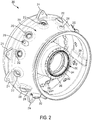
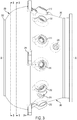
- FIGS. 2-9 illustrate an exemplary monolithic superstructure 200 according to an aspect of the disclosure.
- FIG. 2 illustrates a perspective view of the monolithic superstructure 200.
- the monolithic superstructure 200 may be a superstructure for a combustor in a gas turbine engine.
- the monolithic superstructure 200 is be a single integrated component that performs functions of multiple components in conventional combustors.
- the monolithic superstructure 200 perform functions of an aero component, which typically includes a separate diffuser, deswirler, swirl plate, and diffuser case.
- the monolithic superstructure 200 also performs the functions of a combustor case assembly (e.g., routing fuel, air, and instrumentation to various components of the combustor).
- a combustor case assembly e.g., routing fuel, air, and instrumentation to various components of the combustor.
- the monolithic superstructure 200 also performs the functions of a bearing sump of supporting the shaft and managing turbine cooling air using an inner shroud. As discussed in further detail below, by combining the various functions of combustor components into an integrated component, the monolithic superstructure 200 reduces the total weight of the combustor. The monolithic superstructure 200 also allows for design of optimized paths, thereby requiring lower oil volumes and transport lengths. Further, the monolithic superstructure eliminates assembly risks and fastener failures.
- the monolithic superstructure 200 generally includes an outer case 210 that corresponds to a conventional combustor case and a diffuser case.
- the outer case 210 may include a diffuser case portion 250 at a longitudinally proximal region and a combustor case portion 260 at a longitudinally distal region.
- the outer case 210 includes fuel nozzle ports 212 in the combustor case portion 260 for receiving fuel lines and mounting fuel nozzles.
- the outer case 210 also includes mounting tabs 214 located between the diffuser case portion 250 and the combustor case portion 260. The mounting tabs 214 are spaced about the outer case 210 and extend radially outward.
- the mounting tabs 214 are used to mount the monolithic superstructure 200 to a frame such as a vehicle frame or a generator frame.
- the diffuser case portion 250 includes a compressor flange 252 for mounting to a compressor case.
- the outer case 210 also includes igniter ports 216 for passing an ignition wire through the outer case 210.
- the outer case 210 also includes instrumentation ports 218 for passing instruments and or wires through the outer case 210.
- the outer case 210 also includes cooling air passages 254 for routing cooling air from a forward portion of the monolithic superstructure 200 to an aft component such as a turbine.
- the monolithic superstructure 200 also includes a centrally located bearing sump housing 230.
- the bearing sump housing 230 includes bearing supports 232 for mounting bearings that supporting a shaft 234 (shown in FIG. 4 ).
- the bearing sump housing 230 further includes a conical portion 236 that supports an aero component 300.
- the conical portion 236 is an annular transfer portion extending longitudinally proximally from the bearing supports 232 toward the aero component 300.
- the conical portion 236 transfers a load from the bearing supports 232 to the aero component 300.
- the conical portion 236 is shaped to maintain a position of the aero component 300 with respect to the bearing sump housing 230 and an impeller.
- the bearing sump housing 230 further includes a turbine cooling passage 240 defined between the conical portion 236, the aero component 300, and an inner combustor shroud.
- the turbine cooling passage 240 draws clean air from the aero component 300 and provides the clean air to turbine cooling blades (not shown) via an accelerator 242.
- the inner combustor shroud guides the clean air and also provides a heat shield for the bearing sump housing 230.
- the bearing sump housing further includes a bearing sump sealing surface 244.
- the bearing sump sealing surface 244 may be an inwardly extending flange.
- the bearing sump sealing surface 244 may form a seal for the bearings.
- the bearing sump housing includes a turbine mounting surface 246 for connecting to a turbine.
- the aero component 300 receives air from a compressor impeller 114 and provides compressed air to the combustor.
- the aero component 300 performs functions traditionally performed by a diffuser and a deswirler.
- the compressor impeller 114 may be considered a rotor and the aero component 300 may be considered a stator.
- the aero component 300 divides an interior of the outer case 210 into a forward region and an aft region.
- the aero component 300 is also a load bearing component that transfers loads from the bearing sump housing 230 to the outer case 210 and the mounting tabs 214.
- the aero component 300 includes a diffuser portion 310, a back wall swirl plate 320, deswirler tubes 330, and an aero component support 370.
- FIG. 8 illustrates a lateral cross-section along the line 8-8 in FIG. 3 .
- the diffuser portion 310 is an annular member extending radially inward to an edge 312.
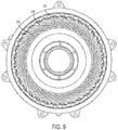
- FIG. 9 illustrates a lateral cross-section along the line 9-9 in FIG. 3 through the diffuser portion 310.
- the diffuser portion 310 includes a plurality of internal passages 314 extending radially outward from the edge 312. The openings of the passages at the edge 312 are aligned with the final compressor impeller.
- the internal passages 314 expand in diameter as they extend from the edge 312 toward the deswirler tubes 330.
- the clearance between the diffuser portion 310 and the compressor impeller may be a performance critical spacing. For example, as the distance between the diffuser portion 310 and the impeller increases, pressurized air is less efficiently transferred to the aero component 300 via the internal passages 314.
- the back wall swirl plate 320 is a plate located aft of the compressor impeller.
- the back wall swirl plate 320 deflects air exiting the compressor impeller to a radially outward direction.
- the back wall swirl plate 320 further includes an impeller backwall stiffener 322.
- the impeller backwall stiffener 322 is an annular member with a triangular cross section that resists forces from the impeller. Further, the impeller backwall stiffener 322 provides frequency tuning to cancel resonant frequency noise generated by the engine.
- the deswirler tubes 330 are a plurality of conjoined tubes that extend from the diffuser portion 310 to the inside of the combustor case portion 260. Each tube first extends radially outward from the diffuser portion 310. Each tube then curves both longitudinally and laterally. In an aspect, the lateral curvature is opposite a direction of the impeller movement. Accordingly, the deswirler tubes 330 reduce lateral swirling of the compressed air.
- the longitudinal curvature of the deswirler tubes 330 extends from the forward region to deswirler outlets 334 located within the combustor case portion 260 in the aft region.
- the deswirler tubes 330 may be the only path from the forward region to the aft region.
- the deswirler tubes 330 may include air extraction ports 332 for turbine cooling and sump pressurization. For example, the air extraction ports may connect an interior of the deswirler tubes 330 to the turbine cooling passage 240.
- the aero component support 370 is an annular member that supports the aero component 300 with respect to the outer case 210.
- the aero component support 370 transfers bearing loads from the aero component 300 to the outer case 210 near the mounting tabs 214.
- the aero component support 370 extends longitudinally and radially from the deswirler tubes 330 to the outer case 210.
- the outer case 210 may be a relatively lower temperature than the aero component 300 and the bearing sump housing 230.
- the aero component 300 may be hotter than the outer case 210 by 200 degrees Fahrenheit (approx. 93,33 degrees Celsius) or more.
- the bearing sump housing 230 may be even hotter than the aero component 300.
- the shape of the aero component support 370 may be selected to maintain the position of the aero component 300 with respect to the impeller as the temperature of the engine increases.
- the aero component support 370 may allow radial expansion of the aero component 300, while resisting longitudinal movement of the aero component 300.
- the radial expansion of the aero component 300 may correspond to radial expansion of the impeller, thereby maintaining a critical clearance between the impeller and the aero component.
- the aero component support 370 maintains an alignment between the impeller and the diffuser portion 310.
- FIG. 10 is a schematic diagram illustrating a load path 1136 for an exemplary superstructure.
- the shaft 126 exerts load on the bearing supports 232.
- the bearing supports 232 transfer the load to the bearing sump housing 230.
- the conical portion 236 transfers the load to the aero component 300.
- the conical portion is connected to the aero component between the back wall swirl plate 320 and the deswirler tubes 330.
- the deswirler tubes 330 transfer the load to the annular aero component support 370.
- the annular aero component support 370 transfers the load to the outer case 210 including the mounting tabs 214.
- the diffuser portion 310 is positioned a critical dimension from the impeller 114.
- the diffuser portion 310 is supported by the conical portion 236 and by the annular aero component support 370 via the deswirler tubes 330. It should be noted, that the diffuser portion 310 is not directly connected to the diffuser case portion 250. Accordingly, the load path 1136 does not include an axial component through the diffuser portion 310, unlike the load path 136 in FIG. 1 .
- the inset 1150 shows a magnified view of the interface between the impeller 114 and the diffuser portion 310. When the impeller 114 and the diffuser portion 310 are cold (e.g., at startup, as illustrated by solid lines), there is a small space between the impeller 114 and the diffuser portion 310.
- the impeller 114 and the diffuser portion 310 are aligned such that compressed air exiting the impeller radially is transferred to the diffuser.
- the hot impeller 1114 may expand radially and shifts forward slightly.
- the hot diffuser 1310 also expands radially and shifts forward slightly. The forward shift may be kept below a threshold. Accordingly, the spacing between the hot impeller 1114 and the hot diffuser 1310 remains approximately the same as the spacing between the cold impeller 114 and the cold diffuser portion 310.
- the critical dimension between the impeller 114 and the diffuser portion 310 is maintained within 10% when the temperature of the system increases by at least 200 degrees Fahrenheit (approx. 93,33 degrees Celsius).
- the hot diffuser 1310 maintains a radial alignment.
- the hot diffuser 1310 maintains the same orientation with respect to the impeller 114. Accordingly, the interface between the impeller 114 and the diffuser portion 310 maintains transfer efficiency as the system heats up.
- the monolithic superstructure 200 may be manufactured using an additive manufacturing (AM) process.
- AM encompasses various manufacturing and prototyping techniques known under a variety of names, including freeform fabrication, 3D printing, rapid prototyping/tooling, etc. AM techniques are capable of fabricating complex components from a wide variety of materials. Generally, a freestanding object can be fabricated from a computer aided design (CAD) model.
- CAD computer aided design
- a particular type of AM process direct metal laser melting (DMLM), uses an energy beam, for example, an electron beam or electromagnetic radiation such as a laser beam, to sinter or melt a powder material, creating a solid three-dimensional object in which particles of the powder material are bonded together.
- DMLM direct metal laser melting
- the AM may be particularly applicable for manufacturing, for example, the monolithic superstructure 200, which includes multiple concentric and coaxial subcomponents.
- the monolithic superstructure 200 may be fabricated in a layer-by-layer manner along the longitudinal axis.
- the AM process may fabricate the monolithic superstructure as an integrated structure.
- Various supports may be used to position portions of the monolithic superstructure during a build process. The supports and any unfused powder may be removed from the monolithic superstructure 200 upon completion.
- additional components such as replaceable bearings, fuel lines, instrumentation, etc. may be mounted to the superstructure.
- one or more of the components described above may be replaced with a similar component mounted to a fixture integrated into the superstructure.
- the monolithic and integrated design of the monolithic superstructure 200 integrates services and features as a single component. Design optimization may be performed for the integrated design rather than at a sub-component level. For example, load paths, case and pressure vessel properties, aerodynamics and related performance, weight, and cost can be optimized as a holistic sub-system design. Additionally, the integrated design allows features (e.g., integrated deswirler tubes 330 and annular aero component support 370) that could not be practically assembled as separate components. The integrated structure also reduces assembly risks related to the functional and physical attributes of separate components. Accordingly, the integrated structure allows for manufacture of a sub-system in a predictable and repeatable manner.
Landscapes
- Engineering & Computer Science (AREA)
- Mechanical Engineering (AREA)
- General Engineering & Computer Science (AREA)
- Chemical & Material Sciences (AREA)
- Combustion & Propulsion (AREA)
- Structures Of Non-Positive Displacement Pumps (AREA)
- Rolling Contact Bearings (AREA)
Claims (11)
- Komponente eines Gasturbinenmotors, umfassend:
einen einstückigen Überbau (200), umfassend:ein äußeres Gehäuse (210) mit einem in Längsrichtung proximalen Diffusorgehäuseabschnitt, mindestens einem Montageflansch und einem in Längsrichtung distalen Brennkammergehäuseabschnitt; undeine Aero-Komponente (300), die über einen ringförmigen Aero-Abschnitt-Träger (370) mit dem äußeren Gehäuse verbunden ist, wobei die Aero-Komponente (300) einen Diffusorabschnitt (310), eine Rückwand-Wirbelplatte (320) und einen EntwirblerAbschnitt umfasst, der eine Mehrzahl verbundener Rohre umfasst, die sich von einem radialen Ende des Diffusorabschnitts (310) zu einem Inneren des Brennkammergehäuseabschnitts erstrecken. - Komponente nach Anspruch 1, wobei der ringförmige Aero-Abschnitt-Träger (370) ein Inneres des äußeren Gehäuses in einen vorderen Bereich und einen hinteren Bereich unterteilt und sich die Mehrzahl verbundener Rohre vom vorderen Bereich zum hinteren Bereich erstrecken.
- Komponente nach Anspruch 1, wobei der Diffusorabschnitt (310) eine kritische Abmessung von einem Laufrad (114) beabstandet ist, so dass der Abstand zwischen dem heißen Laufrad (1114) und dem heißen Diffusor (1310) annähernd gleich dem Abstand zwischen dem kalten Laufrad (114) und dem kalten Diffusorabschnitt (310) bleibt.
- Komponente nach Anspruch 3, wobei die kritische Abmessung innerhalb von 10 % gehalten wird, wenn die Temperatur der Aero-Komponente (300) um mindestens 93,33 °C (200 °Fahrenheit) ansteigt.
- Komponente nach Anspruch 3, wobei der Entwirblerabschnitt ferner eine Rückwandwirbelplatte (320) des Kompressorlaufrads axial hinter dem Laufrad (114) umfasst.
- Verfahren nach Anspruch 1, ferner umfassend:
ein Wannengehäuse (230), das sich von einer axial hinteren Oberfläche der Aero-Komponente (300) erstreckt, wobei das Wannengehäuse (230) einen eingebetteten Turbinenkühlkanal (240) umfasst. - Komponente nach Anspruch 6, wobei die Mehrzahl verbundener Rohre einen Abschnitt einer Außenwand des Wannengehäuses (230) bildet, wobei die Mehrzahl verbundener Rohre eine Mehrzahl von Luftextraktionsöffnungen umfasst, die eine Fluidverbindung zwischen der Mehrzahl verbundener Rohre und einem Inneren des Wannengehäuses (230) bereitstellen.
- Komponente nach Anspruch 7, ferner umfassend einen Turbinenkühlungsbeschleuniger (242), der an einem hinteren Ende des Wannengehäuses (230) angeordnet ist.
- Komponente nach Anspruch 6, ferner umfassend mindestens ein Lager, das sich radial nach innen vom Wannengehäuse (230) erstreckt, wobei das Wannengehäuse (230) eine Lagerbelastung über die Aero-Komponente (300) und den Aero-Abschnitt-Träger auf den mindestens einen Montageflansch verteilt.
- Komponente nach Anspruch 2, wobei das äußere Gehäuse (210) ferner einen Turbinenkühlkanal umfasst, der sich vom vorderen Bereich zu einem hinteren Ende des äußeren Gehäuses erstreckt.
- Komponente nach Anspruch 5, ferner umfassend eine ringförmige Laufradrückwandversteifung (322) mit einem dreieckigen Querschnitt, die sich von einer axial hinteren Oberfläche der Laufradrückwandwirbelplatte (320) erstreckt.
Priority Applications (2)
| Application Number | Priority Date | Filing Date | Title |
|---|---|---|---|
| EP20200997.3A EP3789592B1 (de) | 2016-11-15 | 2017-10-10 | Vorrichtung und verfahren zum verteilen der lagerlast in einem gasturbinentriebwerk |
| EP24157701.4A EP4345260A3 (de) | 2016-11-15 | 2017-10-10 | Vorrichtung und verfahren zur verteilung der lagerlast in einem gasturbinenmotor |
Applications Claiming Priority (2)
| Application Number | Priority Date | Filing Date | Title |
|---|---|---|---|
| US15/352,253 US11174786B2 (en) | 2016-11-15 | 2016-11-15 | Monolithic superstructure for load path optimization |
| PCT/US2017/055847 WO2018093479A1 (en) | 2016-11-15 | 2017-10-10 | Monolithic superstructure for load path optimization |
Related Child Applications (3)
| Application Number | Title | Priority Date | Filing Date |
|---|---|---|---|
| EP20200997.3A Division EP3789592B1 (de) | 2016-11-15 | 2017-10-10 | Vorrichtung und verfahren zum verteilen der lagerlast in einem gasturbinentriebwerk |
| EP20200997.3A Division-Into EP3789592B1 (de) | 2016-11-15 | 2017-10-10 | Vorrichtung und verfahren zum verteilen der lagerlast in einem gasturbinentriebwerk |
| EP24157701.4A Division EP4345260A3 (de) | 2016-11-15 | 2017-10-10 | Vorrichtung und verfahren zur verteilung der lagerlast in einem gasturbinenmotor |
Publications (2)
| Publication Number | Publication Date |
|---|---|
| EP3523508A1 EP3523508A1 (de) | 2019-08-14 |
| EP3523508B1 true EP3523508B1 (de) | 2020-11-25 |
Family
ID=60191472
Family Applications (3)
| Application Number | Title | Priority Date | Filing Date |
|---|---|---|---|
| EP20200997.3A Active EP3789592B1 (de) | 2016-11-15 | 2017-10-10 | Vorrichtung und verfahren zum verteilen der lagerlast in einem gasturbinentriebwerk |
| EP24157701.4A Pending EP4345260A3 (de) | 2016-11-15 | 2017-10-10 | Vorrichtung und verfahren zur verteilung der lagerlast in einem gasturbinenmotor |
| EP17791788.7A Active EP3523508B1 (de) | 2016-11-15 | 2017-10-10 | Monolithisches gehäuse eines gasturbinentriebwerks |
Family Applications Before (2)
| Application Number | Title | Priority Date | Filing Date |
|---|---|---|---|
| EP20200997.3A Active EP3789592B1 (de) | 2016-11-15 | 2017-10-10 | Vorrichtung und verfahren zum verteilen der lagerlast in einem gasturbinentriebwerk |
| EP24157701.4A Pending EP4345260A3 (de) | 2016-11-15 | 2017-10-10 | Vorrichtung und verfahren zur verteilung der lagerlast in einem gasturbinenmotor |
Country Status (6)
| Country | Link |
|---|---|
| US (3) | US11174786B2 (de) |
| EP (3) | EP3789592B1 (de) |
| JP (1) | JP6906832B2 (de) |
| CN (1) | CN110168200A (de) |
| CA (1) | CA3042869C (de) |
| WO (1) | WO2018093479A1 (de) |
Families Citing this family (14)
| Publication number | Priority date | Publication date | Assignee | Title |
|---|---|---|---|---|
| US10221766B2 (en) * | 2016-04-29 | 2019-03-05 | General Electric Company | Sump assembly for a gas turbine engine |
| US10247106B2 (en) * | 2016-06-15 | 2019-04-02 | General Electric Company | Method and system for rotating air seal with integral flexible heat shield |
| US11174786B2 (en) | 2016-11-15 | 2021-11-16 | General Electric Company | Monolithic superstructure for load path optimization |
| US10781721B2 (en) * | 2018-02-09 | 2020-09-22 | General Electric Company | Integral turbine center frame |
| DE102018202083A1 (de) * | 2018-02-09 | 2019-08-14 | MTU Aero Engines AG | Lagerkammergehäuse für eine strömungsmaschine |
| US10989408B2 (en) | 2018-09-13 | 2021-04-27 | Raytheon Technologies Corporation | Additive integral combustor expansion spring |
| CN209761503U (zh) * | 2019-01-22 | 2019-12-10 | 北京南方斯奈克玛涡轮技术有限公司 | 一种集成主动间隙控制装置的涡轮机匣及涡轮机 |
| FR3096725B1 (fr) * | 2019-05-29 | 2021-05-14 | Safran Helicopter Engines | Module de turbomachine d’aeronef |
| CN112211726B (zh) * | 2020-09-01 | 2021-12-07 | 中国空气动力研究与发展中心低速空气动力研究所 | 一种基于涡喷发动机的持续引气系统 |
| US11512611B2 (en) | 2021-02-09 | 2022-11-29 | General Electric Company | Stator apparatus for a gas turbine engine |
| US11859550B2 (en) | 2021-04-01 | 2024-01-02 | General Electric Company | Compound angle accelerator |
| US11767792B1 (en) * | 2022-06-23 | 2023-09-26 | Pratt & Whitney Canada Corp. | Compressor scroll spigot fit load interface |
| US12044169B2 (en) | 2022-07-22 | 2024-07-23 | General Electric Company | Sump arrangement for a gas turbine engine |
| US12392376B2 (en) * | 2024-01-19 | 2025-08-19 | Pratt & Whitney Canada Corp. | Method of producing a gas turbine engine bearing housing |
Family Cites Families (36)
| Publication number | Priority date | Publication date | Assignee | Title |
|---|---|---|---|---|
| US3319930A (en) | 1961-12-19 | 1967-05-16 | Gen Electric | Stator assembly for turbomachines |
| US4653976A (en) * | 1982-09-30 | 1987-03-31 | General Electric Company | Method of compressing a fluid flow in a multi stage centrifugal impeller |
| US4854126A (en) * | 1985-04-29 | 1989-08-08 | Teledyne Industries, Inc. | Centrifugal compressor diffuser system and method of making same |
| US6547518B1 (en) | 2001-04-06 | 2003-04-15 | General Electric Company | Low hoop stress turbine frame support |
| US6578351B1 (en) * | 2001-08-29 | 2003-06-17 | Pratt & Whitney Canada Corp. | APU core compressor providing cooler air supply |
| FR2860039B1 (fr) | 2003-09-19 | 2005-11-25 | Snecma Moteurs | Realisation de l'etancheite dans un turboreacteur pour le prelevement cabine par joints double sens a lamelles |
| FR2860040B1 (fr) | 2003-09-19 | 2006-02-10 | Snecma Moteurs | Realisation de l'etancheite dans un turboreacteur pour le prelevement cabine par un joint a brosse |
| FR2861129A1 (fr) | 2003-10-21 | 2005-04-22 | Snecma Moteurs | Dispositif de joint a labyrinthe pour moteur a turbine a gaz |
| US7097411B2 (en) * | 2004-04-20 | 2006-08-29 | Honeywell International, Inc. | Turbomachine compressor scroll with load-carrying inlet vanes |
| US7093418B2 (en) | 2004-04-21 | 2006-08-22 | Honeywell International, Inc. | Gas turbine engine including a low pressure sump seal buffer source and thermally isolated sump |
| US7513102B2 (en) | 2005-06-06 | 2009-04-07 | General Electric Company | Integrated counterrotating turbofan |
| US7442006B2 (en) | 2005-08-15 | 2008-10-28 | Honeywell International Inc. | Integral diffuser and deswirler with continuous flow path deflected at assembly |
| FR2904034B1 (fr) * | 2006-07-19 | 2010-11-12 | Snecma | Systeme de refroidissement d'une cavite aval de rouet de compresseur centrifuge. |
| US7777155B2 (en) | 2007-02-21 | 2010-08-17 | United Technologies Corporation | System and method for an integrated additive manufacturing cell for complex components |
| US8147178B2 (en) * | 2008-12-23 | 2012-04-03 | General Electric Company | Centrifugal compressor forward thrust and turbine cooling apparatus |
| US8469309B2 (en) | 2008-12-24 | 2013-06-25 | General Electric Company | Monolithic structure for mounting aircraft engine |
| US20110206502A1 (en) | 2010-02-25 | 2011-08-25 | Samuel Ross Rulli | Turbine shroud support thermal shield |
| US8668442B2 (en) | 2010-06-30 | 2014-03-11 | Honeywell International Inc. | Turbine nozzles and methods of manufacturing the same |
| EP2431574A1 (de) | 2010-09-20 | 2012-03-21 | Siemens Aktiengesellschaft | Gasturbine und Verfahren zum Betrieb der Gasturbine |
| US8506836B2 (en) | 2011-09-16 | 2013-08-13 | Honeywell International Inc. | Methods for manufacturing components from articles formed by additive-manufacturing processes |
| CA2825849A1 (en) | 2011-12-29 | 2013-07-04 | Elliott Company | Hot gas expander inlet casing assembly and method |
| FR2986040B1 (fr) | 2012-01-20 | 2016-03-25 | Turbomeca | Support de palier de turbomachine |
| US20130323473A1 (en) | 2012-05-30 | 2013-12-05 | General Electric Company | Secondary structures for aircraft engines and processes therefor |
| US20140182292A1 (en) | 2012-12-29 | 2014-07-03 | United Technologies Corporation | Integral instrumentation in additively manufactured components of gas turbine engines |
| US9903224B2 (en) | 2012-12-29 | 2018-02-27 | United Technologies Corporation | Scupper channelling in gas turbine modules |
| EP2964960B1 (de) | 2013-03-08 | 2019-06-12 | Rolls-Royce North American Technologies, Inc. | Turbostrahltriebwerk-radialverdichter mit dichtung zwischen zwei diffusorteilen |
| US9644495B2 (en) | 2013-08-20 | 2017-05-09 | Honeywell International Inc. | Thermal isolating service tubes and assemblies thereof for gas turbine engines |
| US20150107256A1 (en) * | 2013-10-17 | 2015-04-23 | Pratt & Whitney Canada Corp. | Combustor for gas turbine engine |
| JP6578563B2 (ja) | 2013-11-06 | 2019-09-25 | ラトガーズ、ザ ステイト ユニバーシティ オブ ニュージャージー | 付加製造プロセスにおける低温固化を利用した多孔質マトリックスからのモノリシック体の製造 |
| FR3013387B1 (fr) | 2013-11-20 | 2015-11-20 | Snecma | Support de palier presentant une geometrie facilitant l'evacuation des noyaux de fonderie |
| US10267179B2 (en) * | 2014-12-31 | 2019-04-23 | General Electric Company | Dirt extraction apparatus for a gas turbine engine |
| US9732633B2 (en) | 2015-03-09 | 2017-08-15 | Caterpillar Inc. | Turbocharger turbine assembly |
| CA2934668C (en) | 2015-07-09 | 2018-11-06 | General Electric Company | Bearing assembly for supporting a rotor shaft of a gas turbine engine |
| US10196980B2 (en) | 2016-02-08 | 2019-02-05 | General Electric Company | Bearing outer race retention during high load events |
| US10544693B2 (en) * | 2016-06-15 | 2020-01-28 | Honeywell International Inc. | Service routing configuration for a gas turbine engine diffuser system |
| US11174786B2 (en) | 2016-11-15 | 2021-11-16 | General Electric Company | Monolithic superstructure for load path optimization |
-
2016
- 2016-11-15 US US15/352,253 patent/US11174786B2/en active Active
-
2017
- 2017-10-10 JP JP2019525796A patent/JP6906832B2/ja active Active
- 2017-10-10 EP EP20200997.3A patent/EP3789592B1/de active Active
- 2017-10-10 EP EP24157701.4A patent/EP4345260A3/de active Pending
- 2017-10-10 EP EP17791788.7A patent/EP3523508B1/de active Active
- 2017-10-10 CA CA3042869A patent/CA3042869C/en active Active
- 2017-10-10 CN CN201780081798.9A patent/CN110168200A/zh active Pending
- 2017-10-10 WO PCT/US2017/055847 patent/WO2018093479A1/en not_active Ceased
-
2021
- 2021-11-15 US US17/526,340 patent/US12000339B2/en active Active
-
2024
- 2024-04-29 US US18/649,607 patent/US20240280052A1/en active Pending
Non-Patent Citations (1)
| Title |
|---|
| None * |
Also Published As
| Publication number | Publication date |
|---|---|
| US20220074346A1 (en) | 2022-03-10 |
| EP3523508A1 (de) | 2019-08-14 |
| US11174786B2 (en) | 2021-11-16 |
| JP2019537683A (ja) | 2019-12-26 |
| CA3042869C (en) | 2021-05-11 |
| EP3789592A1 (de) | 2021-03-10 |
| WO2018093479A1 (en) | 2018-05-24 |
| EP3789592B1 (de) | 2024-02-28 |
| US12000339B2 (en) | 2024-06-04 |
| CA3042869A1 (en) | 2018-05-24 |
| EP4345260A3 (de) | 2024-10-09 |
| JP6906832B2 (ja) | 2021-07-21 |
| CN110168200A (zh) | 2019-08-23 |
| US20240280052A1 (en) | 2024-08-22 |
| US20180135517A1 (en) | 2018-05-17 |
| EP4345260A2 (de) | 2024-04-03 |
Similar Documents
| Publication | Publication Date | Title |
|---|---|---|
| US12000339B2 (en) | Integral superstructure for load path optimization | |
| CN111335973B (zh) | 用于燃气涡轮发动机的护罩密封 | |
| EP3081755B1 (de) | Gasturbinenkomponente mit integriertem wärmerohr | |
| EP3241994B1 (de) | System und verfahren zum kühlen von komponenten eines gasturbinenmotors | |
| CN106894845B (zh) | 用于多壁叶片的冷却回路 | |
| EP3447384B1 (de) | Brennkammerplattenkühlanordnungen | |
| US10233775B2 (en) | Engine component for a gas turbine engine | |
| EP3597865A1 (de) | Turbinenschaufelanordnung mit keramischen matrixverbundkomponenten | |
| EP3062021A1 (de) | Vor ort austauschbare brennstoffdüsenvorrichtung, system und verfahren | |
| CN106468182A (zh) | 用于燃气涡轮发动机的具有分离端壁的cmc喷嘴 | |
| EP2938857B2 (de) | Hitzeschild zur kühlung einer strebe | |
| US20180156056A1 (en) | Additive manufactured case with internal passages for active clearance control | |
| US20190257206A1 (en) | Engine component with cooling hole | |
| JP2017122445A (ja) | 多重壁翼のための冷却回路 | |
| EP3214274B1 (de) | Eingekapselte kühlung für turbinenummantelungen | |
| US11662096B2 (en) | Combustor swirler to pseudo-dome attachment and interface with a CMC dome | |
| CN106121828A (zh) | 附接组件和具有附接组件的燃气涡轮发动机 | |
| JP2017141809A (ja) | 多重壁翼のための冷却回路 | |
| US20220260016A1 (en) | Combustor for gas turbine engine and method of manufacture | |
| US20180291812A1 (en) | Turbine engine conduit interface | |
| EP3431710A1 (de) | Abschirmung für eine turbinenmotorschaufel | |
| CN111886087A (zh) | 包括通过增材制造生产的内部冷却壁的涡轮定子叶片 | |
| WO2017196498A1 (en) | Engine component wall with a cooling circuit | |
| KR20170113185A (ko) | 트랜지션 덕트 조립체 |
Legal Events
| Date | Code | Title | Description |
|---|---|---|---|
| STAA | Information on the status of an ep patent application or granted ep patent |
Free format text: STATUS: UNKNOWN |
|
| STAA | Information on the status of an ep patent application or granted ep patent |
Free format text: STATUS: THE INTERNATIONAL PUBLICATION HAS BEEN MADE |
|
| PUAI | Public reference made under article 153(3) epc to a published international application that has entered the european phase |
Free format text: ORIGINAL CODE: 0009012 |
|
| STAA | Information on the status of an ep patent application or granted ep patent |
Free format text: STATUS: REQUEST FOR EXAMINATION WAS MADE |
|
| 17P | Request for examination filed |
Effective date: 20190510 |
|
| AK | Designated contracting states |
Kind code of ref document: A1 Designated state(s): AL AT BE BG CH CY CZ DE DK EE ES FI FR GB GR HR HU IE IS IT LI LT LU LV MC MK MT NL NO PL PT RO RS SE SI SK SM TR |
|
| AX | Request for extension of the european patent |
Extension state: BA ME |
|
| DAV | Request for validation of the european patent (deleted) | ||
| DAX | Request for extension of the european patent (deleted) | ||
| GRAP | Despatch of communication of intention to grant a patent |
Free format text: ORIGINAL CODE: EPIDOSNIGR1 |
|
| STAA | Information on the status of an ep patent application or granted ep patent |
Free format text: STATUS: GRANT OF PATENT IS INTENDED |
|
| INTG | Intention to grant announced |
Effective date: 20200617 |
|
| RIN1 | Information on inventor provided before grant (corrected) |
Inventor name: WILLIAMS, CHRISTOPHER Inventor name: MANTEIGA, JOHN, ALAN Inventor name: MOOK, JOSHUA, TYLER |
|
| GRAS | Grant fee paid |
Free format text: ORIGINAL CODE: EPIDOSNIGR3 |
|
| GRAA | (expected) grant |
Free format text: ORIGINAL CODE: 0009210 |
|
| STAA | Information on the status of an ep patent application or granted ep patent |
Free format text: STATUS: THE PATENT HAS BEEN GRANTED |
|
| AK | Designated contracting states |
Kind code of ref document: B1 Designated state(s): AL AT BE BG CH CY CZ DE DK EE ES FI FR GB GR HR HU IE IS IT LI LT LU LV MC MK MT NL NO PL PT RO RS SE SI SK SM TR |
|
| REG | Reference to a national code |
Ref country code: GB Ref legal event code: FG4D |
|
| REG | Reference to a national code |
Ref country code: CH Ref legal event code: EP |
|
| REG | Reference to a national code |
Ref country code: AT Ref legal event code: REF Ref document number: 1338551 Country of ref document: AT Kind code of ref document: T Effective date: 20201215 |
|
| REG | Reference to a national code |
Ref country code: DE Ref legal event code: R096 Ref document number: 602017028434 Country of ref document: DE |
|
| REG | Reference to a national code |
Ref country code: IE Ref legal event code: FG4D |
|
| REG | Reference to a national code |
Ref country code: AT Ref legal event code: MK05 Ref document number: 1338551 Country of ref document: AT Kind code of ref document: T Effective date: 20201125 |
|
| REG | Reference to a national code |
Ref country code: NL Ref legal event code: MP Effective date: 20201125 |
|
| PG25 | Lapsed in a contracting state [announced via postgrant information from national office to epo] |
Ref country code: FI Free format text: LAPSE BECAUSE OF FAILURE TO SUBMIT A TRANSLATION OF THE DESCRIPTION OR TO PAY THE FEE WITHIN THE PRESCRIBED TIME-LIMIT Effective date: 20201125 Ref country code: RS Free format text: LAPSE BECAUSE OF FAILURE TO SUBMIT A TRANSLATION OF THE DESCRIPTION OR TO PAY THE FEE WITHIN THE PRESCRIBED TIME-LIMIT Effective date: 20201125 Ref country code: PT Free format text: LAPSE BECAUSE OF FAILURE TO SUBMIT A TRANSLATION OF THE DESCRIPTION OR TO PAY THE FEE WITHIN THE PRESCRIBED TIME-LIMIT Effective date: 20210325 Ref country code: GR Free format text: LAPSE BECAUSE OF FAILURE TO SUBMIT A TRANSLATION OF THE DESCRIPTION OR TO PAY THE FEE WITHIN THE PRESCRIBED TIME-LIMIT Effective date: 20210226 Ref country code: NO Free format text: LAPSE BECAUSE OF FAILURE TO SUBMIT A TRANSLATION OF THE DESCRIPTION OR TO PAY THE FEE WITHIN THE PRESCRIBED TIME-LIMIT Effective date: 20210225 |
|
| PG25 | Lapsed in a contracting state [announced via postgrant information from national office to epo] |
Ref country code: AT Free format text: LAPSE BECAUSE OF FAILURE TO SUBMIT A TRANSLATION OF THE DESCRIPTION OR TO PAY THE FEE WITHIN THE PRESCRIBED TIME-LIMIT Effective date: 20201125 Ref country code: SE Free format text: LAPSE BECAUSE OF FAILURE TO SUBMIT A TRANSLATION OF THE DESCRIPTION OR TO PAY THE FEE WITHIN THE PRESCRIBED TIME-LIMIT Effective date: 20201125 Ref country code: PL Free format text: LAPSE BECAUSE OF FAILURE TO SUBMIT A TRANSLATION OF THE DESCRIPTION OR TO PAY THE FEE WITHIN THE PRESCRIBED TIME-LIMIT Effective date: 20201125 Ref country code: IS Free format text: LAPSE BECAUSE OF FAILURE TO SUBMIT A TRANSLATION OF THE DESCRIPTION OR TO PAY THE FEE WITHIN THE PRESCRIBED TIME-LIMIT Effective date: 20210325 Ref country code: LV Free format text: LAPSE BECAUSE OF FAILURE TO SUBMIT A TRANSLATION OF THE DESCRIPTION OR TO PAY THE FEE WITHIN THE PRESCRIBED TIME-LIMIT Effective date: 20201125 Ref country code: BG Free format text: LAPSE BECAUSE OF FAILURE TO SUBMIT A TRANSLATION OF THE DESCRIPTION OR TO PAY THE FEE WITHIN THE PRESCRIBED TIME-LIMIT Effective date: 20210225 |
|
| REG | Reference to a national code |
Ref country code: LT Ref legal event code: MG9D |
|
| PG25 | Lapsed in a contracting state [announced via postgrant information from national office to epo] |
Ref country code: HR Free format text: LAPSE BECAUSE OF FAILURE TO SUBMIT A TRANSLATION OF THE DESCRIPTION OR TO PAY THE FEE WITHIN THE PRESCRIBED TIME-LIMIT Effective date: 20201125 |
|
| PG25 | Lapsed in a contracting state [announced via postgrant information from national office to epo] |
Ref country code: SK Free format text: LAPSE BECAUSE OF FAILURE TO SUBMIT A TRANSLATION OF THE DESCRIPTION OR TO PAY THE FEE WITHIN THE PRESCRIBED TIME-LIMIT Effective date: 20201125 Ref country code: RO Free format text: LAPSE BECAUSE OF FAILURE TO SUBMIT A TRANSLATION OF THE DESCRIPTION OR TO PAY THE FEE WITHIN THE PRESCRIBED TIME-LIMIT Effective date: 20201125 Ref country code: EE Free format text: LAPSE BECAUSE OF FAILURE TO SUBMIT A TRANSLATION OF THE DESCRIPTION OR TO PAY THE FEE WITHIN THE PRESCRIBED TIME-LIMIT Effective date: 20201125 Ref country code: CZ Free format text: LAPSE BECAUSE OF FAILURE TO SUBMIT A TRANSLATION OF THE DESCRIPTION OR TO PAY THE FEE WITHIN THE PRESCRIBED TIME-LIMIT Effective date: 20201125 Ref country code: LT Free format text: LAPSE BECAUSE OF FAILURE TO SUBMIT A TRANSLATION OF THE DESCRIPTION OR TO PAY THE FEE WITHIN THE PRESCRIBED TIME-LIMIT Effective date: 20201125 Ref country code: SM Free format text: LAPSE BECAUSE OF FAILURE TO SUBMIT A TRANSLATION OF THE DESCRIPTION OR TO PAY THE FEE WITHIN THE PRESCRIBED TIME-LIMIT Effective date: 20201125 |
|
| REG | Reference to a national code |
Ref country code: DE Ref legal event code: R097 Ref document number: 602017028434 Country of ref document: DE |
|
| PG25 | Lapsed in a contracting state [announced via postgrant information from national office to epo] |
Ref country code: DK Free format text: LAPSE BECAUSE OF FAILURE TO SUBMIT A TRANSLATION OF THE DESCRIPTION OR TO PAY THE FEE WITHIN THE PRESCRIBED TIME-LIMIT Effective date: 20201125 |
|
| PLBE | No opposition filed within time limit |
Free format text: ORIGINAL CODE: 0009261 |
|
| STAA | Information on the status of an ep patent application or granted ep patent |
Free format text: STATUS: NO OPPOSITION FILED WITHIN TIME LIMIT |
|
| PG25 | Lapsed in a contracting state [announced via postgrant information from national office to epo] |
Ref country code: NL Free format text: LAPSE BECAUSE OF FAILURE TO SUBMIT A TRANSLATION OF THE DESCRIPTION OR TO PAY THE FEE WITHIN THE PRESCRIBED TIME-LIMIT Effective date: 20201125 Ref country code: AL Free format text: LAPSE BECAUSE OF FAILURE TO SUBMIT A TRANSLATION OF THE DESCRIPTION OR TO PAY THE FEE WITHIN THE PRESCRIBED TIME-LIMIT Effective date: 20201125 Ref country code: IT Free format text: LAPSE BECAUSE OF FAILURE TO SUBMIT A TRANSLATION OF THE DESCRIPTION OR TO PAY THE FEE WITHIN THE PRESCRIBED TIME-LIMIT Effective date: 20201125 |
|
| 26N | No opposition filed |
Effective date: 20210826 |
|
| PG25 | Lapsed in a contracting state [announced via postgrant information from national office to epo] |
Ref country code: SI Free format text: LAPSE BECAUSE OF FAILURE TO SUBMIT A TRANSLATION OF THE DESCRIPTION OR TO PAY THE FEE WITHIN THE PRESCRIBED TIME-LIMIT Effective date: 20201125 |
|
| PG25 | Lapsed in a contracting state [announced via postgrant information from national office to epo] |
Ref country code: ES Free format text: LAPSE BECAUSE OF FAILURE TO SUBMIT A TRANSLATION OF THE DESCRIPTION OR TO PAY THE FEE WITHIN THE PRESCRIBED TIME-LIMIT Effective date: 20201125 |
|
| REG | Reference to a national code |
Ref country code: CH Ref legal event code: PL |
|
| PG25 | Lapsed in a contracting state [announced via postgrant information from national office to epo] |
Ref country code: IS Free format text: LAPSE BECAUSE OF FAILURE TO SUBMIT A TRANSLATION OF THE DESCRIPTION OR TO PAY THE FEE WITHIN THE PRESCRIBED TIME-LIMIT Effective date: 20210325 |
|
| REG | Reference to a national code |
Ref country code: BE Ref legal event code: MM Effective date: 20211031 |
|
| PG25 | Lapsed in a contracting state [announced via postgrant information from national office to epo] |
Ref country code: MC Free format text: LAPSE BECAUSE OF FAILURE TO SUBMIT A TRANSLATION OF THE DESCRIPTION OR TO PAY THE FEE WITHIN THE PRESCRIBED TIME-LIMIT Effective date: 20201125 |
|
| PG25 | Lapsed in a contracting state [announced via postgrant information from national office to epo] |
Ref country code: LU Free format text: LAPSE BECAUSE OF NON-PAYMENT OF DUE FEES Effective date: 20211010 Ref country code: BE Free format text: LAPSE BECAUSE OF NON-PAYMENT OF DUE FEES Effective date: 20211031 |
|
| PG25 | Lapsed in a contracting state [announced via postgrant information from national office to epo] |
Ref country code: LI Free format text: LAPSE BECAUSE OF NON-PAYMENT OF DUE FEES Effective date: 20211031 Ref country code: CH Free format text: LAPSE BECAUSE OF NON-PAYMENT OF DUE FEES Effective date: 20211031 |
|
| PG25 | Lapsed in a contracting state [announced via postgrant information from national office to epo] |
Ref country code: IE Free format text: LAPSE BECAUSE OF NON-PAYMENT OF DUE FEES Effective date: 20211010 |
|
| P01 | Opt-out of the competence of the unified patent court (upc) registered |
Effective date: 20230411 |
|
| PG25 | Lapsed in a contracting state [announced via postgrant information from national office to epo] |
Ref country code: CY Free format text: LAPSE BECAUSE OF FAILURE TO SUBMIT A TRANSLATION OF THE DESCRIPTION OR TO PAY THE FEE WITHIN THE PRESCRIBED TIME-LIMIT Effective date: 20201125 |
|
| PG25 | Lapsed in a contracting state [announced via postgrant information from national office to epo] |
Ref country code: HU Free format text: LAPSE BECAUSE OF FAILURE TO SUBMIT A TRANSLATION OF THE DESCRIPTION OR TO PAY THE FEE WITHIN THE PRESCRIBED TIME-LIMIT; INVALID AB INITIO Effective date: 20171010 |
|
| PG25 | Lapsed in a contracting state [announced via postgrant information from national office to epo] |
Ref country code: MK Free format text: LAPSE BECAUSE OF FAILURE TO SUBMIT A TRANSLATION OF THE DESCRIPTION OR TO PAY THE FEE WITHIN THE PRESCRIBED TIME-LIMIT Effective date: 20201125 |
|
| PG25 | Lapsed in a contracting state [announced via postgrant information from national office to epo] |
Ref country code: MT Free format text: LAPSE BECAUSE OF FAILURE TO SUBMIT A TRANSLATION OF THE DESCRIPTION OR TO PAY THE FEE WITHIN THE PRESCRIBED TIME-LIMIT Effective date: 20201125 |
|
| PGFP | Annual fee paid to national office [announced via postgrant information from national office to epo] |
Ref country code: GB Payment date: 20250923 Year of fee payment: 9 |
|
| PGFP | Annual fee paid to national office [announced via postgrant information from national office to epo] |
Ref country code: FR Payment date: 20250923 Year of fee payment: 9 |
|
| PG25 | Lapsed in a contracting state [announced via postgrant information from national office to epo] |
Ref country code: TR Free format text: LAPSE BECAUSE OF FAILURE TO SUBMIT A TRANSLATION OF THE DESCRIPTION OR TO PAY THE FEE WITHIN THE PRESCRIBED TIME-LIMIT Effective date: 20201125 |
|
| PGFP | Annual fee paid to national office [announced via postgrant information from national office to epo] |
Ref country code: DE Payment date: 20250923 Year of fee payment: 9 |