EP3523142B1 - Tire with audible functionality - Google Patents
Tire with audible functionality Download PDFInfo
- Publication number
- EP3523142B1 EP3523142B1 EP17859154.1A EP17859154A EP3523142B1 EP 3523142 B1 EP3523142 B1 EP 3523142B1 EP 17859154 A EP17859154 A EP 17859154A EP 3523142 B1 EP3523142 B1 EP 3523142B1
- Authority
- EP
- European Patent Office
- Prior art keywords
- ply
- lattice
- tire
- tread
- annular
- Prior art date
- Legal status (The legal status is an assumption and is not a legal conclusion. Google has not performed a legal analysis and makes no representation as to the accuracy of the status listed.)
- Active
Links
Images




Classifications
-
- B—PERFORMING OPERATIONS; TRANSPORTING
- B60—VEHICLES IN GENERAL
- B60C—VEHICLE TYRES; TYRE INFLATION; TYRE CHANGING; CONNECTING VALVES TO INFLATABLE ELASTIC BODIES IN GENERAL; DEVICES OR ARRANGEMENTS RELATED TO TYRES
- B60C11/00—Tyre tread bands; Tread patterns; Anti-skid inserts
- B60C11/24—Wear-indicating arrangements
-
- B—PERFORMING OPERATIONS; TRANSPORTING
- B60—VEHICLES IN GENERAL
- B60C—VEHICLE TYRES; TYRE INFLATION; TYRE CHANGING; CONNECTING VALVES TO INFLATABLE ELASTIC BODIES IN GENERAL; DEVICES OR ARRANGEMENTS RELATED TO TYRES
- B60C11/00—Tyre tread bands; Tread patterns; Anti-skid inserts
- B60C11/14—Anti-skid inserts, e.g. vulcanised into the tread band
-
- B—PERFORMING OPERATIONS; TRANSPORTING
- B60—VEHICLES IN GENERAL
- B60C—VEHICLE TYRES; TYRE INFLATION; TYRE CHANGING; CONNECTING VALVES TO INFLATABLE ELASTIC BODIES IN GENERAL; DEVICES OR ARRANGEMENTS RELATED TO TYRES
- B60C11/00—Tyre tread bands; Tread patterns; Anti-skid inserts
- B60C11/24—Wear-indicating arrangements
- B60C11/243—Tread wear sensors, e.g. electronic sensors
-
- B—PERFORMING OPERATIONS; TRANSPORTING
- B60—VEHICLES IN GENERAL
- B60C—VEHICLE TYRES; TYRE INFLATION; TYRE CHANGING; CONNECTING VALVES TO INFLATABLE ELASTIC BODIES IN GENERAL; DEVICES OR ARRANGEMENTS RELATED TO TYRES
- B60C11/00—Tyre tread bands; Tread patterns; Anti-skid inserts
- B60C11/0008—Tyre tread bands; Tread patterns; Anti-skid inserts characterised by the tread rubber
- B60C2011/0016—Physical properties or dimensions
- B60C2011/0025—Modulus or tan delta
-
- B—PERFORMING OPERATIONS; TRANSPORTING
- B60—VEHICLES IN GENERAL
- B60C—VEHICLE TYRES; TYRE INFLATION; TYRE CHANGING; CONNECTING VALVES TO INFLATABLE ELASTIC BODIES IN GENERAL; DEVICES OR ARRANGEMENTS RELATED TO TYRES
- B60C19/00—Tyre parts or constructions not otherwise provided for
- B60C2019/006—Warning devices, e.g. devices generating noise due to flat or worn tyres
-
- B—PERFORMING OPERATIONS; TRANSPORTING
- B60—VEHICLES IN GENERAL
- B60C—VEHICLE TYRES; TYRE INFLATION; TYRE CHANGING; CONNECTING VALVES TO INFLATABLE ELASTIC BODIES IN GENERAL; DEVICES OR ARRANGEMENTS RELATED TO TYRES
- B60C19/00—Tyre parts or constructions not otherwise provided for
- B60C2019/006—Warning devices, e.g. devices generating noise due to flat or worn tyres
- B60C2019/007—Warning devices, e.g. devices generating noise due to flat or worn tyres triggered by sensors
Definitions
- This invention relates to structures and methods used to notify a driver, passenger, or other observer that a tire tread has worn to a predetermined limit. More particularly, the invention relates to lattice plies, lattices and/or meshes disposed within a tire that produce an audible signal that indicates a tire tread has worn to the predetermined limit.
- the lattice plies, lattices and/or meshes may be used in a variety of tire applications, including without limitation, passenger, light truck, and truck-and-bus radial applications.
- tread wear indicators provide a visual indication that a tire tread has worn to a predetermined limit, and the "penny test" (i.e., inserting a penny into a groove to measure the height of a tread element relative to a feature of the coin) and direct measurements have been used to ascertain tread depth.
- penny test i.e., inserting a penny into a groove to measure the height of a tread element relative to a feature of the coin
- direct measurements have been used to ascertain tread depth.
- a tire comprising first and second annular beads with a body ply extending between the first and second annular beads
- an annular belt package including first and second annular belts extends axially across a portion of the body ply.
- a circumferential tread including a tread cap and a tread base is disposed radially above the annular belt package, and a lattice ply comprising nodes and a connective medium is disposed radially between the annular belt package and the tread cap.
- a similar tire is also known from DE 199 35 255 A1 and US 5,303,756 A .
- a tire as defined in claim 1 and method of making a tire as defined in claim 8 are provided.
- Figure 1 is a peel-away cross-sectional perspective view of an embodiment of a pneumatic tire 100.
- Tire 100 includes a first annular bead 105 and a second annular bead 110.
- the annular beads in part, secure the tire to a wheel.
- the tire comprises four or more beads.
- tire 100 further includes a body ply 115 extending between first annular bead 105 and second annular bead 110.
- Body ply 115 forms an annulus and imparts shape to the tire.
- body ply 115 may contain reinforcing cords (not labeled) or fabric (not shown). In alternative embodiments (not shown), various turn-up and turn-down configurations, or multiple body plies, are used.
- Tire 100 further includes an annular belt package which includes a first annular belt 120 and a second annular belt 125.
- First annular belt 120 is disposed radially upward of body ply 115 and extends axially across a portion of body ply 115.
- Second annular belt 125 is disposed radially upward of first annular belt 120 and extends axially across a portion of body ply 115.
- the annular belts may contain steel cords and reinforcing cords (both not shown).
- the belt package includes a third annular belt.
- tire 100 further comprises a cap ply 130.
- Cap ply 130 is disposed radially above first annular belt 120 and second annular belt 125.
- Cap ply 130 extends axially across a portion of body ply 115.
- a sealing gel layer is provided in the cap ply region.
- Tire 100 further comprises a circumferential tread 135.
- Circumferential tread 135 is disposed radially upward of cap ply 130 (and the belt package) and extends axially across a portion of body ply 115.
- the width of the circumferential tread 135 is known as the tread width.
- four circumferential grooves divide circumferential tread 135 into five ribs.
- a circumferential tread may contain additional elements such as, without limitation, axial grooves, sacrificial ribs, sipes, stone ejectors, and tie bars.
- the circumferential tread is affixed to the tire ( e.g., by vulcanization) when the tire is new.
- the circumferential tread is affixed as a retread.
- Tire 100 further comprises a first sidewall 140 and a second sidewall 145.
- First sidewall 140 extends between the first annular bead 105 and a first shoulder 150, which is proximately associated with an edge of circumferential tread 135.
- Second sidewall 145 extends between the second annular bead 110 and a second shoulder 155, which is proximately associated with an opposite edge of circumferential tread 135.
- the sidewall includes one or more sidewall protector(s), electronic device(s), and/or cooling fin(s).
- Tire 100 includes a lattice ply 160 that comprises nodes 165 and a connective medium 170.
- Lattice ply 160 is disposed radially above cap ply 130, and expends axially across a portion of body ply 115.
- the lattice ply has a width between 20 and 100% of the tread width.
- the lattice ply has a width between 40 and 90% of the tread width.
- nodes 165 protrude from lattice ply 160 into circumferential tread 135, but are wholly contained by the tread 135. As circumferential tread 135 wears due to use, nodes 165 become exposed and will contact the road. In contacting the road, nodes 165 will produce an audible signal that indicates circumferential tread 135 is worn.
- the nodes extend into a tread cap (which is not shown). In an alternative embodiment, the nodes extend to the surface of a tread base (also not shown). In an alternative embodiment, the nodes extend only into a tread base.
- nodes 165 are rectangular prisms. In an alternative embodiment (not shown), the nodes have a domed surface. In another alternative embodiment, the nodes have a flared base. As one of ordinary skill in the art will understand, the nodes may be a variety of three-dimensional shapes.
- the nodes are made of a durable material having a Shore A hardness of between 70 and 100. In an alternative embodiment, the nodes are made of a durable material having a Shore A hardness of between 75 and 90. In a second embodiment, the nodes have a Shore D hardness between 50 and 100. In an alternative embodiment, the the nodes have a Shore D hardness between 70 and 90.
- connective medium 170 is a thin sheet or film of material that extends (at least partially) between the edges of lattice ply 160.
- the connective medium is an elastomer.
- the connective medium is selected from the group consisting of fabrics, synthetic polymers, plastics, and thermoplastics.
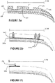
- Figure 2a is a front cross-sectional view of an example of the tire including the lattice ply 160 shown in Figure 1 , which is not part of the claimed invention. Like elements are identified with like numbering.
- tread 135 further includes a tread cap 175 and a tread base 180.
- Tread base 180 is disposed radially upward of cap ply 130 (and the belt package) and extends axially across a portion of body ply 115.
- Tread cap 175 is disposed radially upward of tread base 180 and extends axially across a portion of body ply 115.
- Tread cap 175 may be formulated to possess particular performance attributes that are desirable when the tire is new. As one of ordinary skill in the art will understand, the tread cap and tread base are normally made of different compounds.
- lattice ply 160 is embedded within tread base 180. Nodes 165 extend from lattice ply 160, through tread base 180, into tread cap 165.
- the lattice ply (including the nodes) may be co-extruded with the tread base. In an alternative embodiment, the lattice ply is laid upon a given tire component.
- Figure 2b is a front cross-sectional view of an alternative example of the tire including a lattice ply 160 shown in Figure 2a , which is not part of the claimed invention.
- the Figure 2b example is substantially the same as the Figure 2a example, except for the differences discussed below.
- the tire shown in Figure 2b is a casing suitable for use in retread applications.
- the tread (or retread) portion of the tire is omitted from the figure.
- the nodes 165b have a domed tip.
- nodes 165b are spaced unevenly along the same axial line.
- one node is disposed in a middle region of the tread (such as a rib) and two nodes are disposed on an outer region of the tread (such as a rib).
- the nodes extend from the lattice ply 160b through the tire.
- Figure 2c is a front cross-sectional view of alternative example of the tire including a lattice ply shown in Figure 2a , which is not part of the claimed invention.
- the Figure 2c example is substantially the same as the Figure 2b example, except for the differences discussed below.
- lattice ply 160c is disposed at the top surface of the tire casing.
- Node 165c which is shown as having a pointed tip, extends out of lattice ply 160c.
- lattice ply 160c has a width between 5 and 30% of the tread width.
- FIG 3a is a representative schematic drawing illustrating one embodiment of a lattice 200a for use in a tire.
- Lattice 200a is an example of a particular type of lattice ply having audible functionality.
- Lattice 200a includes axial filaments 205a and 205b and circumferential filaments 210a and 210b.
- Axial filaments 205a and 205b and circumferential filaments 210a and 210b are two examples of connecting filaments.
- lattice 200a includes a plurality of connecting filaments.
- Axial filaments 205a and 205b are disposed perpendicular to the direction of travel DOT, while the circumferential filaments are disposed parallel to the direction of travel DOT.
- the circumferential filaments are only approximately circumferential, and are in fact disposed at an acute angle relative to the circumferential direction (e.g., under 45° divergence from the circumferential direction) and the axial filaments are only approximately axial, and are in fact disposed at an acute angle relative to the axial direction ( e . g ., under 45° divergence from the axial direction).
- the axial and/or circumferential filaments are disposed at a 45° with respect to the direction of travel.
- axial filaments 205a and 205b meet circumferential filaments 210a and 210b at intersection 215a.
- lattice 200a includes a plurality of intersections. The intersections define a plurality of interstices.
- the axial filaments are spaced between 5 and 20 cm apart. In an alternative embodiment, the axial filaments are spaced between 0.5 and 2.0 cm apart.
- lattice 200a further includes cores 220a and 220b.
- cores 220a and 220b have a generally symmetrical upper and lower half. As a tire tread wears due to use, the cores will become exposed and will contact the road. In contacting the road, the cores will produce an audible signal that indicates the tire tread is worn.
- axial filament 205b connects to core 220a.
- circumferential filaments e.g., 210a and 210b
- cores e.g., 220a and 220b.
- lattice 200a includes a plurality of cores.
- filaments connect to the cores by passing through them.
- the filaments connect to the cores by surrounding or at least partially surrounding the cores.
- the cores encapsulate polyurethane foam which expands when the cores breach.
- the connecting filaments are made of material selected from the group consisting of nylon, rayon, aramid, para-aramid, polyester, polyethylene, polyethylene naphthalate (PEN), polyethylene terephthalate (PET), polyvinyl alcohol (PVOH or PVA), polybenzobisoxazole (PBO or Zylon), ethylene carbon monoxide copolymer (POK), carbon fiber, fiberglass, steel, and aluminum.
- the cores may be made of material selected from the group consisting of PVC, phenol formaldehyde resins, nylon, polystyrene, polyethylene, polypropylene, polyoxymethylene, polyphenylene oxide, polyphenylene sulphide, polyester, polyurethane, acrylonitrile, and butadiene styrene.
- Figure 3b is a representative schematic drawing illustrating an alternative embodiment of a lattice 200b for use in a tire.
- the Figure 3b embodiment is substantially the same as the Figure 3a embodiment, except for the differences discussed below.
- Lattice 200b includes a plurality of cores 220a. As shown, the plurality of cores is disposed over disparate axial filaments (205b-d) rather than at the interstices. Disposing the cores over disparate axial filaments alters the audible noise produced when the cores contact the road. In a particular embodiment (not shown), a linear distance of 10 to 20 cm separates adjacent cores. In an alternative embodiment, a linear distance of 2 to 10 cm separates adjacent cores.
- Figure 3c is a representative schematic drawing illustrating another alternative embodiment of a lattice 200c for use in a tire.
- Lattice 200c includes octagonal filaments 225 that form interstices 230 and common edges 235.
- Octagonal filaments 225 further include connecting filaments 240 that connect to cores 220a.
- different polygonal shapes are used in lieu of octagons.
- filament 245 surrounds core 220a.
- the cores include a notch to receive a connecting filament.
- FIG. 3d is a representative schematic drawing illustrating an alternative embodiment of a mesh 200d for use in a tire.
- Mesh 200d is an example of a particular type of lattice ply having audible functionality.
- a plurality of filaments 250 is provided, and a portion of the filaments secure cores 220b.
- multiple filaments are connected to each core.
- Edge 255 is depicted for illustrative purposes only.
- Figure 3e is a representative schematic drawing illustrating one embodiment of a mesh 200e for use in a tire.
- the Figure 3e embodiment is substantially the same as the Figure 3d embodiment, except for that mesh 200e is provided in conjunction with a lattice (as discussed with relation to Figures 3a-3c ) to simplify the tire manufacturing process.
- Figure 3f is a representative schematic drawing illustrating one example of a film 200f for use in a tire, which is not part of the claimed invention.
- Film 200f is an example of a particular type of lattice ply having audible functionality.
- the Figure 3f example is substantially the same as the Figure 3a embodiment, except for the differences discussed below.
- film 200f secures cores 200b.
- Film 200f is made of a plastic (or other thin polymeric material) and at least partially surrounds cores 220b ( e.g., the cores are embedded in the film).
- the cores are disposed between two films.
- the cores are affixed to the film with an adhesive.
- cores 220b are unevenly distributed across film medium 260.
- the cores are distributed within a 5 cm linear distance with respect to the direction of travel.
- the cores are distributed within a 2 cm linear distance with respect to the direction of travel.
- the film is provided in conjunction with a lattice (as discussed with relation to Figures 3a-3c ).
- Figure 4 is close-up top plan view of fibers 300 suitable for use in a tire.
- Fibers 300 may be assembled into a lattice, mesh, or circumferential band that constitute a particular type of lattice ply having audible functionality. This particular type of lattice ply does not contain nodes or cores.
- fibers 300 include a first plurality of polyurethane domains 310 and a second plurality of polyurethane domains 315.
- the polyurethane domains in the second plurality of polyurethane domains 315 are harder than the polyurethane domains in the first plurality of polyurethane domains 310.
- the polyurethane domains in the second plurality of polyurethane domains emit an audible signal when they contact the road.
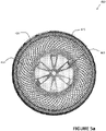
- Figure 5a is a side cross-sectional view of a tire 400 including a lattice ply 415.
- tire 400 is a non-pneumatic tire, with wheel 405, spokes 410, and tread 420 shown for context.
- Lattice ply 415 is disposed radially between spokes 410 and tread 420. As tread 420 wears due to use, lattice ply 415 will become exposed and will contact the road. In contacting the road, lattice ply 415 will produce an audible signal that indicates tread 420 is worn.
- Figure 5b is a side cross-sectional view of an alternative embodiment of a tire including a lattice 415.
- the Figure 5b embodiment is substantially the same as the Figure 5a embodiment, except for the differences discussed below.
- nodes 425a, 425b, and 425c extend from lattice 415 into tread 420.
- the nodes are disposed within one quadrant of the tire.
- the nodes are distributed in disparate quadrants.
Landscapes
- Engineering & Computer Science (AREA)
- Mechanical Engineering (AREA)
- Tires In General (AREA)
Description
- This invention relates to structures and methods used to notify a driver, passenger, or other observer that a tire tread has worn to a predetermined limit. More particularly, the invention relates to lattice plies, lattices and/or meshes disposed within a tire that produce an audible signal that indicates a tire tread has worn to the predetermined limit. The lattice plies, lattices and/or meshes may be used in a variety of tire applications, including without limitation, passenger, light truck, and truck-and-bus radial applications.
- Structures and methods for gauging tread wear are known. For example, tread wear indicators provide a visual indication that a tire tread has worn to a predetermined limit, and the "penny test" (i.e., inserting a penny into a groove to measure the height of a tread element relative to a feature of the coin) and direct measurements have been used to ascertain tread depth. These structures and tests require physical observation (when the tire is stationary) in order to determine the tread depth.
- From
US 2004/154715 A1 , a tire comprising first and second annular beads with a body ply extending between the first and second annular beads is known, wherein an annular belt package including first and second annular belts extends axially across a portion of the body ply. A circumferential tread including a tread cap and a tread base is disposed radially above the annular belt package, and a lattice ply comprising nodes and a connective medium is disposed radially between the annular belt package and the tread cap. A similar tire is also known fromDE 199 35 255 A1 andUS 5,303,756 A . - According to the invention, a tire as defined in
claim 1 and method of making a tire as defined in claim 8 are provided. - The dependent claims define preferred and/or advantageous embodiments of the invention.
- In the accompanying drawings, structures are illustrated that, together with the detailed description provided below, describe exemplary embodiments of the claimed invention. Like elements are identified with the same reference numerals. It should be understood that elements shown as a single component may be replaced with multiple components, and elements shown as multiple components may be replaced with a single component. The drawings are not to scale and the proportion of certain elements may be exaggerated for the purpose of illustration.
-
Figure 1 is a peel-away cross-sectional perspective view of an embodiment of a tire including a lattice ply; -
Figure 2a is a front cross-sectional view of the tire including an example for a lattice ply shown inFigure 1 , which is not part of the claimed invention; -
Figure 2b is a front cross-sectional view of an alternative example of a tire and lattice ply, which is not part of the claimed invention; -
Figure 2c is a front cross-sectional view of another alternative example of a tire and lattice ply, which is not part of the claimed invention; -
Figure 3a is a representative schematic drawing illustrating one embodiment of a lattice for use in a tire; -
Figure 3b is a representative schematic drawing illustrating an alternative embodiment of a lattice for use in a tire; -
Figure 3c is a representative schematic drawing illustrating another alternative embodiment of a lattice for use in a tire; -
Figure 3d is a representative schematic drawing illustrating one embodiment of a mesh for use in a tire; -
Figure 3e is a representative schematic drawing illustrating an alternative embodiment of a mesh for use in a tire; -
Figure 3f is a representative schematic drawing illustrating one example of a film for use in a tire, which is not part of the claimed invention; -
Figure 4 is close-up top plan view of one embodiment of fibers suitable for use in a tire; -
Figure 5a is a side cross-sectional view of one embodiment of a non-pneumatic tire including a lattice; and -
Figure 5b is a side cross-sectional view of an alternative embodiment of a non-pneumatic tire including a lattice. -
Figure 1 is a peel-away cross-sectional perspective view of an embodiment of apneumatic tire 100. Tire 100 includes a firstannular bead 105 and a secondannular bead 110. The annular beads, in part, secure the tire to a wheel. In an alternative embodiment (not shown), the tire comprises four or more beads. - As shown,
tire 100 further includes abody ply 115 extending between firstannular bead 105 and secondannular bead 110.Body ply 115 forms an annulus and imparts shape to the tire. As one of ordinary skill in the art will understand,body ply 115 may contain reinforcing cords (not labeled) or fabric (not shown). In alternative embodiments (not shown), various turn-up and turn-down configurations, or multiple body plies, are used. - Tire 100 further includes an annular belt package which includes a first
annular belt 120 and a secondannular belt 125. Firstannular belt 120 is disposed radially upward ofbody ply 115 and extends axially across a portion ofbody ply 115. Secondannular belt 125 is disposed radially upward of firstannular belt 120 and extends axially across a portion ofbody ply 115. As one of ordinary skill in the art will understand, the annular belts may contain steel cords and reinforcing cords (both not shown). In an alternative embodiment (not shown), the belt package includes a third annular belt. - As illustrated in
Figure 1 ,tire 100 further comprises acap ply 130. Capply 130 is disposed radially above firstannular belt 120 and secondannular belt 125. Capply 130 extends axially across a portion ofbody ply 115. In an alternative embodiment (not shown), a sealing gel layer is provided in the cap ply region. - Tire 100 further comprises a
circumferential tread 135.Circumferential tread 135 is disposed radially upward of cap ply 130 (and the belt package) and extends axially across a portion ofbody ply 115. The width of thecircumferential tread 135 is known as the tread width. As depicted, four circumferential grooves dividecircumferential tread 135 into five ribs. As one of ordinary skill in the art will understand, a circumferential tread may contain additional elements such as, without limitation, axial grooves, sacrificial ribs, sipes, stone ejectors, and tie bars. As one of ordinary skill in the art will also understand, the circumferential tread is affixed to the tire (e.g., by vulcanization) when the tire is new. In an alternative embodiment (not shown), the circumferential tread is affixed as a retread. - Tire 100 further comprises a
first sidewall 140 and asecond sidewall 145.First sidewall 140 extends between the firstannular bead 105 and afirst shoulder 150, which is proximately associated with an edge ofcircumferential tread 135.Second sidewall 145 extends between the secondannular bead 110 and asecond shoulder 155, which is proximately associated with an opposite edge ofcircumferential tread 135. In alternative embodiments (not shown), the sidewall includes one or more sidewall protector(s), electronic device(s), and/or cooling fin(s). - Tire 100 includes a
lattice ply 160 that comprisesnodes 165 and a connective medium 170.Lattice ply 160 is disposed radially abovecap ply 130, and expends axially across a portion ofbody ply 115. In one embodiment, the lattice ply has a width between 20 and 100% of the tread width. In an alternative embodiment (not shown), the lattice ply has a width between 40 and 90% of the tread width. - With continued reference to
Figure 1 ,nodes 165 protrude from lattice ply 160 intocircumferential tread 135, but are wholly contained by thetread 135. Ascircumferential tread 135 wears due to use,nodes 165 become exposed and will contact the road. In contacting the road,nodes 165 will produce an audible signal that indicatescircumferential tread 135 is worn. In one embodiment (not shown), the nodes extend into a tread cap (which is not shown). In an alternative embodiment, the nodes extend to the surface of a tread base (also not shown). In an alternative embodiment, the nodes extend only into a tread base. - As illustrated in
Figure 1 ,nodes 165 are rectangular prisms. In an alternative embodiment (not shown), the nodes have a domed surface. In another alternative embodiment, the nodes have a flared base. As one of ordinary skill in the art will understand, the nodes may be a variety of three-dimensional shapes. - In one embodiment, the nodes are made of a durable material having a Shore A hardness of between 70 and 100. In an alternative embodiment, the nodes are made of a durable material having a Shore A hardness of between 75 and 90. In a second embodiment, the nodes have a Shore D hardness between 50 and 100. In an alternative embodiment, the the nodes have a Shore D hardness between 70 and 90.
- With continued reference to
Figure 1 , connective medium 170 is a thin sheet or film of material that extends (at least partially) between the edges oflattice ply 160. In one embodiment (not explicitly shown), the connective medium is an elastomer. In alternative embodiments, the connective medium is selected from the group consisting of fabrics, synthetic polymers, plastics, and thermoplastics. -
Figure 2a is a front cross-sectional view of an example of the tire including the lattice ply 160 shown inFigure 1 , which is not part of the claimed invention. Like elements are identified with like numbering. - As shown in
Figure 2a , tread 135 further includes atread cap 175 and atread base 180.Tread base 180 is disposed radially upward of cap ply 130 (and the belt package) and extends axially across a portion of body ply 115.Tread cap 175 is disposed radially upward oftread base 180 and extends axially across a portion of body ply 115.Tread cap 175 may be formulated to possess particular performance attributes that are desirable when the tire is new. As one of ordinary skill in the art will understand, the tread cap and tread base are normally made of different compounds. - As further shown in
Figure 2a , lattice ply 160 is embedded withintread base 180.Nodes 165 extend fromlattice ply 160, throughtread base 180, intotread cap 165. The lattice ply (including the nodes) may be co-extruded with the tread base. In an alternative embodiment, the lattice ply is laid upon a given tire component. -
Figure 2b is a front cross-sectional view of an alternative example of the tire including alattice ply 160 shown inFigure 2a , which is not part of the claimed invention. TheFigure 2b example is substantially the same as theFigure 2a example, except for the differences discussed below. - In this example, the tire shown in
Figure 2b is a casing suitable for use in retread applications. The tread (or retread) portion of the tire is omitted from the figure. As shown, thenodes 165b have a domed tip. Further,nodes 165b are spaced unevenly along the same axial line. For this half of the tire, one node is disposed in a middle region of the tread (such as a rib) and two nodes are disposed on an outer region of the tread (such as a rib). In this particular example, the nodes extend from thelattice ply 160b through the tire. -
Figure 2c is a front cross-sectional view of alternative example of the tire including a lattice ply shown inFigure 2a , which is not part of the claimed invention. TheFigure 2c example is substantially the same as theFigure 2b example, except for the differences discussed below. - In this example,
lattice ply 160c is disposed at the top surface of the tire casing.Node 165c, which is shown as having a pointed tip, extends out oflattice ply 160c. Further, as shown,lattice ply 160c has a width between 5 and 30% of the tread width. -
Figure 3a is a representative schematic drawing illustrating one embodiment of alattice 200a for use in a tire.Lattice 200a is an example of a particular type of lattice ply having audible functionality. -
Lattice 200a includesaxial filaments circumferential filaments Axial filaments circumferential filaments lattice 200a includes a plurality of connecting filaments.Axial filaments - As shown in
Figure 3a ,axial filaments circumferential filaments intersection 215a. As shown,lattice 200a includes a plurality of intersections. The intersections define a plurality of interstices. In one embodiment (not shown), the axial filaments are spaced between 5 and 20 cm apart. In an alternative embodiment, the axial filaments are spaced between 0.5 and 2.0 cm apart. - As shown in
Figure 3a ,lattice 200a further includescores nodes 165,cores - As shown,
axial filament 205b connects tocore 220a. Likewise, the circumferential filaments, e.g., 210a and 210b, also connect to the cores, e.g., 220a and 220b. As shown,lattice 200a includes a plurality of cores. In one embodiment (not shown), filaments connect to the cores by passing through them. In further alternative embodiments, the filaments connect to the cores by surrounding or at least partially surrounding the cores. In yet another alternative embodiment, the cores encapsulate polyurethane foam which expands when the cores breach. - Although not shown in
Figure 3a , the connecting filaments are made of material selected from the group consisting of nylon, rayon, aramid, para-aramid, polyester, polyethylene, polyethylene naphthalate (PEN), polyethylene terephthalate (PET), polyvinyl alcohol (PVOH or PVA), polybenzobisoxazole (PBO or Zylon), ethylene carbon monoxide copolymer (POK), carbon fiber, fiberglass, steel, and aluminum. The cores may be made of material selected from the group consisting of PVC, phenol formaldehyde resins, nylon, polystyrene, polyethylene, polypropylene, polyoxymethylene, polyphenylene oxide, polyphenylene sulphide, polyester, polyurethane, acrylonitrile, and butadiene styrene. -
Figure 3b is a representative schematic drawing illustrating an alternative embodiment of alattice 200b for use in a tire. TheFigure 3b embodiment is substantially the same as theFigure 3a embodiment, except for the differences discussed below. -
Lattice 200b includes a plurality ofcores 220a. As shown, the plurality of cores is disposed over disparate axial filaments (205b-d) rather than at the interstices. Disposing the cores over disparate axial filaments alters the audible noise produced when the cores contact the road. In a particular embodiment (not shown), a linear distance of 10 to 20 cm separates adjacent cores. In an alternative embodiment, a linear distance of 2 to 10 cm separates adjacent cores. -
Figure 3c is a representative schematic drawing illustrating another alternative embodiment of alattice 200c for use in a tire. -
Lattice 200c includesoctagonal filaments 225 that forminterstices 230 andcommon edges 235.Octagonal filaments 225 further include connectingfilaments 240 that connect tocores 220a. In alternative embodiments (not shown), different polygonal shapes are used in lieu of octagons. - With continued reference to
Figure 3c ,filament 245 surroundscore 220a. In an alternative embodiment (not shown), the cores include a notch to receive a connecting filament. -
Figure 3d is a representative schematic drawing illustrating an alternative embodiment of amesh 200d for use in a tire.Mesh 200d is an example of a particular type of lattice ply having audible functionality. - In
mesh 200d, a plurality offilaments 250 is provided, and a portion of the filaments securecores 220b. In contrast to the lattices shown inFigures 3a-3c , multiple filaments are connected to each core.Edge 255 is depicted for illustrative purposes only. -
Figure 3e is a representative schematic drawing illustrating one embodiment of amesh 200e for use in a tire. TheFigure 3e embodiment is substantially the same as theFigure 3d embodiment, except for thatmesh 200e is provided in conjunction with a lattice (as discussed with relation toFigures 3a-3c ) to simplify the tire manufacturing process. -
Figure 3f is a representative schematic drawing illustrating one example of afilm 200f for use in a tire, which is not part of the claimed invention.Film 200f is an example of a particular type of lattice ply having audible functionality. TheFigure 3f example is substantially the same as theFigure 3a embodiment, except for the differences discussed below. - In
Figure 3f ,film 200f securescores 200b.Film 200f is made of a plastic (or other thin polymeric material) and at least partially surroundscores 220b (e.g., the cores are embedded in the film). In an alternative example (not shown), the cores are disposed between two films. In another alternative example, the cores are affixed to the film with an adhesive. - As shown in
Figure 3f ,cores 220b are unevenly distributed acrossfilm medium 260. In one example (not shown), the cores are distributed within a 5 cm linear distance with respect to the direction of travel. In an alternative example, the cores are distributed within a 2 cm linear distance with respect to the direction of travel. In another alternative example, the film is provided in conjunction with a lattice (as discussed with relation toFigures 3a-3c ). -
Figure 4 is close-up top plan view offibers 300 suitable for use in a tire.Fibers 300 may be assembled into a lattice, mesh, or circumferential band that constitute a particular type of lattice ply having audible functionality. This particular type of lattice ply does not contain nodes or cores. - In the illustrated example,
fibers 300 include a first plurality ofpolyurethane domains 310 and a second plurality ofpolyurethane domains 315. The polyurethane domains in the second plurality ofpolyurethane domains 315 are harder than the polyurethane domains in the first plurality ofpolyurethane domains 310. Although not shown, the polyurethane domains in the second plurality of polyurethane domains emit an audible signal when they contact the road. -
Figure 5a is a side cross-sectional view of atire 400 including alattice ply 415. As shown,tire 400 is a non-pneumatic tire, withwheel 405,spokes 410, and tread 420 shown for context. Lattice ply 415 is disposed radially betweenspokes 410 andtread 420. Astread 420 wears due to use, lattice ply 415 will become exposed and will contact the road. In contacting the road, lattice ply 415 will produce an audible signal that indicatestread 420 is worn. -
Figure 5b is a side cross-sectional view of an alternative embodiment of a tire including alattice 415. TheFigure 5b embodiment is substantially the same as theFigure 5a embodiment, except for the differences discussed below. - As shown in
Figure 5b ,nodes lattice 415 intotread 420. In the illustrated embodiment, the nodes are disposed within one quadrant of the tire. In an alternative embodiment (not shown), the nodes are distributed in disparate quadrants. - To the extent that the term "includes" or "including" is used in the specification or the claims, it is intended to be inclusive in a manner similar to the term "comprising" as that term is interpreted when employed as a transitional word in a claim. Furthermore, to the extent that the term "or" is employed (e.g., A or B) it is intended to mean "A or B or both." When the applicants intend to indicate "only A or B but not both" then the term "only A or B but not both" will be employed. Thus, use of the term "or" herein is the inclusive, and not the exclusive use. See, Bryan A. Garner, A Dictionary of Modern Legal Usage 624 (2d. Ed. 1995). Also, to the extent that the terms "in" or "into" are used in the specification or the claims, it is intended to additionally mean "on" or "onto." Furthermore, to the extent the term "connect" is used in the specification or claims, it is intended to mean not only "directly connected to," but also "indirectly connected to" such as connected through another component or components.
- While the present invention has been illustrated by the description of embodiments thereof, and while the embodiments have been described in considerable detail, it is not the intention of the applicants to restrict or in any way limit the scope of the appended claims to such detail. Additional advantages and modifications will readily appear to those skilled in the art. Therefore, the invention, in its broader aspects, is not limited to the specific details, the representative apparatus and method, and illustrative examples shown and described. Accordingly, departures may be made from such details without departing from the scope of the applicant's inventive concept as defined in the appended claims.
Claims (13)
- A tire (100) comprising:a first annular bead (105) and a second annular bead (110);a body ply (115) extending between the first annular bead (105) and the second annular bead (110);an annular belt package (120, 125), including a first annular belt (120), disposed radially upward of the body ply (115) and extending axially across a portion of the body ply (115), and a second annular belt (125), disposed radially upward of the first annular belt (120) and extending axially across a portion of the body ply (115);a circumferential tread (135), disposed radially above the annular belt package (120, 125), including at least a tread cap (175) and a tread base (180), both of which extend axially across a portion of the body ply (115);a lattice ply (200a; 200b; 200c) comprising a plurality of spaced apart axial filaments (205a, 205b; 235) and a plurality of nodes (165; 165b; 165c; 220a; 220b) having a three-dimensional shape and a Shore D hardness between 50 and 100, wherein the lattice ply (200a; 200b; 200c) is disposed radially between the annular belt package (120, 125) and the tread cap (175), and extends axially across a portion of the body ply (115); anda first sidewall (140) extending between the first annular bead (105) and a first shoulder (150), the first shoulder (150) being associated with the circumferential tread (135), and a second sidewall (145) extending between the second annular bead (110) and a second shoulder (155), the second shoulder (155) being associated with the circumferential tread (135).
- The tire (100) of claim 1, wherein the nodes (165; 165b; 165c; 220a; 220b) have a domed surface.
- The tire (100) of claim 1 or claim 2, wherein the nodes (165; 165b; 165c; 220a; 220b) extend into the tread cap (175).
- The tire (100) of any one of claims 1-3, wherein the lattice ply (200a; 200b; 200c) has a width between 20 and 100% of a width of the circumferential tread (135).
- The tire (100) of any one of claims 1-4, wherein at least three nodes (165; 165b; 165c; 220a; 220b) are disposed on disparate axial lines.
- The tire (100) of any one of claims 1-5, wherein the axial filaments (205a, 205b; 235) are spaced between 5 and 20 cm apart.
- The tire (100) of any one of claims 1-6, wherein at least a portion of the axial filaments (205a, 205b; 235) at least partially surround the nodes (165; 165b; 165c; 220a; 220b).
- A method of making a tire (100; 400) comprising:forming an annular structure configured to interface with a wheel (405);forming a circumferential tread (135; 420) in a crown region of the tire (100; 400), the circumferential tread (135; 420) including a tread cap (175);providing a lattice ply (200a; 200b; 200c; 415) having a plurality of spaced apart axial filaments (205a, 205b; 235) and a plurality of nodes (165; 165b; 165c; 220a; 220b) with a three-dimensional shape and a Shore D hardness between 50 and 100; andextending the lattice ply (200a; 200b; 200c; 415) axially across a portion of the annular structure at a location radially between the annular structure and the tread cap (175), such that the lattice ply (200a; 200b; 200c; 415) produces audible noise when exposed to a traveling surface.
- The method of claim 8, wherein the step of forming the circumferential tread (135; 420) includes forming the tread cap (175) and a tread base (180).
- The method of claim 9, wherein the step of extending the lattice ply (200a; 200b; 200c; 415) axially across a portion of the annular structure includes extending the lattice ply (200a; 200b; 200c; 415) axially across a portion of the annular structure at a location radially between the tread cap (175) and the tread base (180).
- The method of any one of claims 8-10, wherein the step of providing a lattice ply (200a; 200b; 200c; 415) includes providing a lattice ply (200a; 200b; 200c; 415) having interstices (230).
- The method of any one of claims 8-11, wherein the step of providing a lattice ply (200a; 200b; 200c; 415) includes providing a lattice ply (200a; 200b; 200c; 415) having protrusions which are disposed radially below outer thirds of the circumferential tread (135; 420).
- The method of any one of claims 8-12, wherein the step of providing a lattice ply (200a; 200b; 200c; 415) includes providing a lattice ply (200a; 200b; 200c; 415) having encapsulated urethane foam.
Applications Claiming Priority (2)
| Application Number | Priority Date | Filing Date | Title |
|---|---|---|---|
| US201662404895P | 2016-10-06 | 2016-10-06 | |
| PCT/US2017/055234 WO2018067766A1 (en) | 2016-10-06 | 2017-10-05 | Tire with audible functionality |
Publications (3)
| Publication Number | Publication Date |
|---|---|
| EP3523142A1 EP3523142A1 (en) | 2019-08-14 |
| EP3523142A4 EP3523142A4 (en) | 2020-07-01 |
| EP3523142B1 true EP3523142B1 (en) | 2022-08-03 |
Family
ID=61832195
Family Applications (1)
| Application Number | Title | Priority Date | Filing Date |
|---|---|---|---|
| EP17859154.1A Active EP3523142B1 (en) | 2016-10-06 | 2017-10-05 | Tire with audible functionality |
Country Status (3)
| Country | Link |
|---|---|
| US (1) | US20200047561A1 (en) |
| EP (1) | EP3523142B1 (en) |
| WO (1) | WO2018067766A1 (en) |
Families Citing this family (3)
| Publication number | Priority date | Publication date | Assignee | Title |
|---|---|---|---|---|
| IT201800021031A1 (en) * | 2018-12-24 | 2020-06-24 | Bridgestone Europe Nv Sa | TIRE WITH STRIPS POSITIONED UNDER THE TREAD TO REDUCE THE NOISE OF THE TIRES |
| US12427809B2 (en) | 2020-11-19 | 2025-09-30 | Regents Of The University Of Minnesota | Non-pneumatic tire |
| CN115891514A (en) * | 2022-11-25 | 2023-04-04 | 山东玲珑轮胎股份有限公司 | Novel vocal music wearing and tearing sign tire |
Citations (1)
| Publication number | Priority date | Publication date | Assignee | Title |
|---|---|---|---|---|
| US20090294025A1 (en) * | 2008-05-29 | 2009-12-03 | Michiels Dany F | Process for Forming Pneumatic Tire with Leno Cap Ply |
Family Cites Families (9)
| Publication number | Priority date | Publication date | Assignee | Title |
|---|---|---|---|---|
| US3929179A (en) * | 1973-12-05 | 1975-12-30 | Kennametal Inc | Indicator device for indicating tread wear and tire incorporating the indicator |
| US5303756A (en) * | 1991-09-30 | 1994-04-19 | Hill James L | Tire for indicating tread wear and method of manufacturing the same |
| DE19935255A1 (en) | 1999-07-27 | 2001-02-08 | Franz Andrzejewski | Pneumatic tire has rubber layer of different color embedded in tread at a depth corresponding to the profile groove depth |
| DE19954814A1 (en) * | 1999-11-13 | 2001-05-31 | Daimler Chrysler Ag | Car tire has a wear indicator which shows when tread has worn down to minimum level |
| FR2816887B1 (en) | 2000-11-20 | 2003-03-14 | Dufournier Technologies | METHOD AND DEVICE FOR DETECTING THE WEAR OF TIRES OR TREADS AND SIMILAR SURFACES OR ZONES |
| US20070044889A1 (en) * | 2005-09-01 | 2007-03-01 | Bridgestone Firestone North American Tire, Llc | Tire having a sidewall reinforcement |
| JP5216077B2 (en) * | 2010-12-29 | 2013-06-19 | 住友ゴム工業株式会社 | Heavy duty pneumatic tire |
| US9649889B2 (en) * | 2012-12-13 | 2017-05-16 | The Goodyear Tire & Rubber Company | Autonomous, plug-in wear or abrasion sensing system |
| JP6475340B2 (en) * | 2014-12-31 | 2019-02-27 | ブリヂストン アメリカズ タイヤ オペレーションズ、 エルエルシー | RFID wear detection for tire applications |
-
2017
- 2017-10-05 US US16/339,410 patent/US20200047561A1/en not_active Abandoned
- 2017-10-05 WO PCT/US2017/055234 patent/WO2018067766A1/en not_active Ceased
- 2017-10-05 EP EP17859154.1A patent/EP3523142B1/en active Active
Patent Citations (1)
| Publication number | Priority date | Publication date | Assignee | Title |
|---|---|---|---|---|
| US20090294025A1 (en) * | 2008-05-29 | 2009-12-03 | Michiels Dany F | Process for Forming Pneumatic Tire with Leno Cap Ply |
Also Published As
| Publication number | Publication date |
|---|---|
| US20200047561A1 (en) | 2020-02-13 |
| EP3523142A1 (en) | 2019-08-14 |
| EP3523142A4 (en) | 2020-07-01 |
| WO2018067766A1 (en) | 2018-04-12 |
Similar Documents
| Publication | Publication Date | Title |
|---|---|---|
| US11993040B2 (en) | Composite layer tire | |
| JP7192433B2 (en) | pneumatic tire | |
| US10442251B2 (en) | Pneumatic tire with side wall decorative portion | |
| US10639935B2 (en) | Tire with tensioned spokes | |
| CN101134427A (en) | Heavy duty tire | |
| JP6111792B2 (en) | Pneumatic tire | |
| CN102463856A (en) | Puncture sealant laminate | |
| US11904561B2 (en) | Tire with shaped tread | |
| CN106132726B (en) | Retreads | |
| CN109789734A (en) | Tires with optimized structure | |
| WO2018067766A1 (en) | Tire with audible functionality | |
| WO2017116823A1 (en) | Tire with variable shear element | |
| CN107128129A (en) | Pneumatic tire | |
| JP2012086836A (en) | Tire and self-inflation apparatus assembly | |
| CN109803838A (en) | With the tire including working lining for improving structure | |
| EP3031622A1 (en) | Tire having wear indicator | |
| US20180001715A1 (en) | Tire tread for reducing noise | |
| US20210197627A1 (en) | Pneumatic tire | |
| CN100469606C (en) | Locked bead pneumatic tire with wrap-around toeguard | |
| US11127315B2 (en) | Modular display system | |
| US20200114693A1 (en) | Tire | |
| US11235626B2 (en) | Pneumatic tire | |
| JP2006044487A (en) | Pneumatic radial tire | |
| CN121969508A (en) | tire | |
| US10406865B2 (en) | Repair boundary indicator for tires |
Legal Events
| Date | Code | Title | Description |
|---|---|---|---|
| STAA | Information on the status of an ep patent application or granted ep patent |
Free format text: STATUS: THE INTERNATIONAL PUBLICATION HAS BEEN MADE |
|
| PUAI | Public reference made under article 153(3) epc to a published international application that has entered the european phase |
Free format text: ORIGINAL CODE: 0009012 |
|
| STAA | Information on the status of an ep patent application or granted ep patent |
Free format text: STATUS: REQUEST FOR EXAMINATION WAS MADE |
|
| 17P | Request for examination filed |
Effective date: 20190502 |
|
| AK | Designated contracting states |
Kind code of ref document: A1 Designated state(s): AL AT BE BG CH CY CZ DE DK EE ES FI FR GB GR HR HU IE IS IT LI LT LU LV MC MK MT NL NO PL PT RO RS SE SI SK SM TR |
|
| AX | Request for extension of the european patent |
Extension state: BA ME |
|
| RIN1 | Information on inventor provided before grant (corrected) |
Inventor name: AGARWAL, SHEEL P. Inventor name: WEI, TERENCE E. |
|
| DAV | Request for validation of the european patent (deleted) | ||
| DAX | Request for extension of the european patent (deleted) | ||
| A4 | Supplementary search report drawn up and despatched |
Effective date: 20200603 |
|
| RIC1 | Information provided on ipc code assigned before grant |
Ipc: B60C 11/24 20060101ALI20200527BHEP Ipc: B60C 19/00 20060101AFI20200527BHEP |
|
| STAA | Information on the status of an ep patent application or granted ep patent |
Free format text: STATUS: EXAMINATION IS IN PROGRESS |
|
| 17Q | First examination report despatched |
Effective date: 20210127 |
|
| GRAP | Despatch of communication of intention to grant a patent |
Free format text: ORIGINAL CODE: EPIDOSNIGR1 |
|
| STAA | Information on the status of an ep patent application or granted ep patent |
Free format text: STATUS: GRANT OF PATENT IS INTENDED |
|
| INTG | Intention to grant announced |
Effective date: 20220322 |
|
| GRAS | Grant fee paid |
Free format text: ORIGINAL CODE: EPIDOSNIGR3 |
|
| GRAA | (expected) grant |
Free format text: ORIGINAL CODE: 0009210 |
|
| STAA | Information on the status of an ep patent application or granted ep patent |
Free format text: STATUS: THE PATENT HAS BEEN GRANTED |
|
| AK | Designated contracting states |
Kind code of ref document: B1 Designated state(s): AL AT BE BG CH CY CZ DE DK EE ES FI FR GB GR HR HU IE IS IT LI LT LU LV MC MK MT NL NO PL PT RO RS SE SI SK SM TR |
|
| REG | Reference to a national code |
Ref country code: AT Ref legal event code: REF Ref document number: 1508457 Country of ref document: AT Kind code of ref document: T Effective date: 20220815 Ref country code: CH Ref legal event code: EP |
|
| REG | Reference to a national code |
Ref country code: DE Ref legal event code: R096 Ref document number: 602017060323 Country of ref document: DE |
|
| REG | Reference to a national code |
Ref country code: IE Ref legal event code: FG4D |
|
| REG | Reference to a national code |
Ref country code: LT Ref legal event code: MG9D |
|
| REG | Reference to a national code |
Ref country code: NL Ref legal event code: MP Effective date: 20220803 |
|
| PG25 | Lapsed in a contracting state [announced via postgrant information from national office to epo] |
Ref country code: SE Free format text: LAPSE BECAUSE OF FAILURE TO SUBMIT A TRANSLATION OF THE DESCRIPTION OR TO PAY THE FEE WITHIN THE PRESCRIBED TIME-LIMIT Effective date: 20220803 Ref country code: RS Free format text: LAPSE BECAUSE OF FAILURE TO SUBMIT A TRANSLATION OF THE DESCRIPTION OR TO PAY THE FEE WITHIN THE PRESCRIBED TIME-LIMIT Effective date: 20220803 Ref country code: PT Free format text: LAPSE BECAUSE OF FAILURE TO SUBMIT A TRANSLATION OF THE DESCRIPTION OR TO PAY THE FEE WITHIN THE PRESCRIBED TIME-LIMIT Effective date: 20221205 Ref country code: NO Free format text: LAPSE BECAUSE OF FAILURE TO SUBMIT A TRANSLATION OF THE DESCRIPTION OR TO PAY THE FEE WITHIN THE PRESCRIBED TIME-LIMIT Effective date: 20221103 Ref country code: NL Free format text: LAPSE BECAUSE OF FAILURE TO SUBMIT A TRANSLATION OF THE DESCRIPTION OR TO PAY THE FEE WITHIN THE PRESCRIBED TIME-LIMIT Effective date: 20220803 Ref country code: LV Free format text: LAPSE BECAUSE OF FAILURE TO SUBMIT A TRANSLATION OF THE DESCRIPTION OR TO PAY THE FEE WITHIN THE PRESCRIBED TIME-LIMIT Effective date: 20220803 Ref country code: LT Free format text: LAPSE BECAUSE OF FAILURE TO SUBMIT A TRANSLATION OF THE DESCRIPTION OR TO PAY THE FEE WITHIN THE PRESCRIBED TIME-LIMIT Effective date: 20220803 Ref country code: FI Free format text: LAPSE BECAUSE OF FAILURE TO SUBMIT A TRANSLATION OF THE DESCRIPTION OR TO PAY THE FEE WITHIN THE PRESCRIBED TIME-LIMIT Effective date: 20220803 Ref country code: ES Free format text: LAPSE BECAUSE OF FAILURE TO SUBMIT A TRANSLATION OF THE DESCRIPTION OR TO PAY THE FEE WITHIN THE PRESCRIBED TIME-LIMIT Effective date: 20220803 |
|
| REG | Reference to a national code |
Ref country code: AT Ref legal event code: MK05 Ref document number: 1508457 Country of ref document: AT Kind code of ref document: T Effective date: 20220803 |
|
| PG25 | Lapsed in a contracting state [announced via postgrant information from national office to epo] |
Ref country code: PL Free format text: LAPSE BECAUSE OF FAILURE TO SUBMIT A TRANSLATION OF THE DESCRIPTION OR TO PAY THE FEE WITHIN THE PRESCRIBED TIME-LIMIT Effective date: 20220803 Ref country code: IS Free format text: LAPSE BECAUSE OF FAILURE TO SUBMIT A TRANSLATION OF THE DESCRIPTION OR TO PAY THE FEE WITHIN THE PRESCRIBED TIME-LIMIT Effective date: 20221203 Ref country code: HR Free format text: LAPSE BECAUSE OF FAILURE TO SUBMIT A TRANSLATION OF THE DESCRIPTION OR TO PAY THE FEE WITHIN THE PRESCRIBED TIME-LIMIT Effective date: 20220803 Ref country code: GR Free format text: LAPSE BECAUSE OF FAILURE TO SUBMIT A TRANSLATION OF THE DESCRIPTION OR TO PAY THE FEE WITHIN THE PRESCRIBED TIME-LIMIT Effective date: 20221104 |
|
| PG25 | Lapsed in a contracting state [announced via postgrant information from national office to epo] |
Ref country code: SM Free format text: LAPSE BECAUSE OF FAILURE TO SUBMIT A TRANSLATION OF THE DESCRIPTION OR TO PAY THE FEE WITHIN THE PRESCRIBED TIME-LIMIT Effective date: 20220803 Ref country code: RO Free format text: LAPSE BECAUSE OF FAILURE TO SUBMIT A TRANSLATION OF THE DESCRIPTION OR TO PAY THE FEE WITHIN THE PRESCRIBED TIME-LIMIT Effective date: 20220803 Ref country code: DK Free format text: LAPSE BECAUSE OF FAILURE TO SUBMIT A TRANSLATION OF THE DESCRIPTION OR TO PAY THE FEE WITHIN THE PRESCRIBED TIME-LIMIT Effective date: 20220803 Ref country code: CZ Free format text: LAPSE BECAUSE OF FAILURE TO SUBMIT A TRANSLATION OF THE DESCRIPTION OR TO PAY THE FEE WITHIN THE PRESCRIBED TIME-LIMIT Effective date: 20220803 Ref country code: AT Free format text: LAPSE BECAUSE OF FAILURE TO SUBMIT A TRANSLATION OF THE DESCRIPTION OR TO PAY THE FEE WITHIN THE PRESCRIBED TIME-LIMIT Effective date: 20220803 |
|
| REG | Reference to a national code |
Ref country code: DE Ref legal event code: R097 Ref document number: 602017060323 Country of ref document: DE |
|
| PG25 | Lapsed in a contracting state [announced via postgrant information from national office to epo] |
Ref country code: SK Free format text: LAPSE BECAUSE OF FAILURE TO SUBMIT A TRANSLATION OF THE DESCRIPTION OR TO PAY THE FEE WITHIN THE PRESCRIBED TIME-LIMIT Effective date: 20220803 Ref country code: MC Free format text: LAPSE BECAUSE OF FAILURE TO SUBMIT A TRANSLATION OF THE DESCRIPTION OR TO PAY THE FEE WITHIN THE PRESCRIBED TIME-LIMIT Effective date: 20220803 Ref country code: EE Free format text: LAPSE BECAUSE OF FAILURE TO SUBMIT A TRANSLATION OF THE DESCRIPTION OR TO PAY THE FEE WITHIN THE PRESCRIBED TIME-LIMIT Effective date: 20220803 |
|
| REG | Reference to a national code |
Ref country code: CH Ref legal event code: PL |
|
| PLBE | No opposition filed within time limit |
Free format text: ORIGINAL CODE: 0009261 |
|
| STAA | Information on the status of an ep patent application or granted ep patent |
Free format text: STATUS: NO OPPOSITION FILED WITHIN TIME LIMIT |
|
| REG | Reference to a national code |
Ref country code: BE Ref legal event code: MM Effective date: 20221031 |
|
| P01 | Opt-out of the competence of the unified patent court (upc) registered |
Effective date: 20230524 |
|
| PG25 | Lapsed in a contracting state [announced via postgrant information from national office to epo] |
Ref country code: LU Free format text: LAPSE BECAUSE OF NON-PAYMENT OF DUE FEES Effective date: 20221005 Ref country code: AL Free format text: LAPSE BECAUSE OF FAILURE TO SUBMIT A TRANSLATION OF THE DESCRIPTION OR TO PAY THE FEE WITHIN THE PRESCRIBED TIME-LIMIT Effective date: 20220803 |
|
| 26N | No opposition filed |
Effective date: 20230504 |
|
| GBPC | Gb: european patent ceased through non-payment of renewal fee |
Effective date: 20221103 |
|
| PG25 | Lapsed in a contracting state [announced via postgrant information from national office to epo] |
Ref country code: LI Free format text: LAPSE BECAUSE OF NON-PAYMENT OF DUE FEES Effective date: 20221031 Ref country code: CH Free format text: LAPSE BECAUSE OF NON-PAYMENT OF DUE FEES Effective date: 20221031 |
|
| PG25 | Lapsed in a contracting state [announced via postgrant information from national office to epo] |
Ref country code: SI Free format text: LAPSE BECAUSE OF FAILURE TO SUBMIT A TRANSLATION OF THE DESCRIPTION OR TO PAY THE FEE WITHIN THE PRESCRIBED TIME-LIMIT Effective date: 20220803 |
|
| PG25 | Lapsed in a contracting state [announced via postgrant information from national office to epo] |
Ref country code: BE Free format text: LAPSE BECAUSE OF NON-PAYMENT OF DUE FEES Effective date: 20221031 |
|
| PG25 | Lapsed in a contracting state [announced via postgrant information from national office to epo] |
Ref country code: IE Free format text: LAPSE BECAUSE OF NON-PAYMENT OF DUE FEES Effective date: 20221005 Ref country code: GB Free format text: LAPSE BECAUSE OF NON-PAYMENT OF DUE FEES Effective date: 20221103 |
|
| PG25 | Lapsed in a contracting state [announced via postgrant information from national office to epo] |
Ref country code: HU Free format text: LAPSE BECAUSE OF FAILURE TO SUBMIT A TRANSLATION OF THE DESCRIPTION OR TO PAY THE FEE WITHIN THE PRESCRIBED TIME-LIMIT; INVALID AB INITIO Effective date: 20171005 |
|
| PG25 | Lapsed in a contracting state [announced via postgrant information from national office to epo] |
Ref country code: CY Free format text: LAPSE BECAUSE OF FAILURE TO SUBMIT A TRANSLATION OF THE DESCRIPTION OR TO PAY THE FEE WITHIN THE PRESCRIBED TIME-LIMIT Effective date: 20220803 |
|
| PG25 | Lapsed in a contracting state [announced via postgrant information from national office to epo] |
Ref country code: MK Free format text: LAPSE BECAUSE OF FAILURE TO SUBMIT A TRANSLATION OF THE DESCRIPTION OR TO PAY THE FEE WITHIN THE PRESCRIBED TIME-LIMIT Effective date: 20220803 Ref country code: IT Free format text: LAPSE BECAUSE OF FAILURE TO SUBMIT A TRANSLATION OF THE DESCRIPTION OR TO PAY THE FEE WITHIN THE PRESCRIBED TIME-LIMIT Effective date: 20220803 |
|
| PG25 | Lapsed in a contracting state [announced via postgrant information from national office to epo] |
Ref country code: BG Free format text: LAPSE BECAUSE OF FAILURE TO SUBMIT A TRANSLATION OF THE DESCRIPTION OR TO PAY THE FEE WITHIN THE PRESCRIBED TIME-LIMIT Effective date: 20220803 |
|
| PG25 | Lapsed in a contracting state [announced via postgrant information from national office to epo] |
Ref country code: MT Free format text: LAPSE BECAUSE OF FAILURE TO SUBMIT A TRANSLATION OF THE DESCRIPTION OR TO PAY THE FEE WITHIN THE PRESCRIBED TIME-LIMIT Effective date: 20220803 |
|
| PGFP | Annual fee paid to national office [announced via postgrant information from national office to epo] |
Ref country code: FR Payment date: 20250924 Year of fee payment: 9 |
|
| PG25 | Lapsed in a contracting state [announced via postgrant information from national office to epo] |
Ref country code: TR Free format text: LAPSE BECAUSE OF FAILURE TO SUBMIT A TRANSLATION OF THE DESCRIPTION OR TO PAY THE FEE WITHIN THE PRESCRIBED TIME-LIMIT Effective date: 20220803 |
|
| PGFP | Annual fee paid to national office [announced via postgrant information from national office to epo] |
Ref country code: DE Payment date: 20250923 Year of fee payment: 9 |