EP3522762B1 - Low noise stick vaccum cleaner - Google Patents
Low noise stick vaccum cleaner Download PDFInfo
- Publication number
- EP3522762B1 EP3522762B1 EP16778053.5A EP16778053A EP3522762B1 EP 3522762 B1 EP3522762 B1 EP 3522762B1 EP 16778053 A EP16778053 A EP 16778053A EP 3522762 B1 EP3522762 B1 EP 3522762B1
- Authority
- EP
- European Patent Office
- Prior art keywords
- stick
- vacuum cleaner
- air
- air outlet
- handheld
- Prior art date
- Legal status (The legal status is an assumption and is not a legal conclusion. Google has not performed a legal analysis and makes no representation as to the accuracy of the status listed.)
- Active
Links
- 238000010521 absorption reaction Methods 0.000 claims description 17
- 238000007789 sealing Methods 0.000 claims description 16
- 239000000463 material Substances 0.000 claims description 8
- 239000006096 absorbing agent Substances 0.000 claims description 4
- 238000004140 cleaning Methods 0.000 description 4
- 239000000428 dust Substances 0.000 description 2
- 239000012530 fluid Substances 0.000 description 2
- 239000013589 supplement Substances 0.000 description 2
- 210000002268 wool Anatomy 0.000 description 2
- 229920000742 Cotton Polymers 0.000 description 1
- 239000011358 absorbing material Substances 0.000 description 1
- 239000000356 contaminant Substances 0.000 description 1
- 239000006260 foam Substances 0.000 description 1
- 238000009413 insulation Methods 0.000 description 1
- 239000004033 plastic Substances 0.000 description 1
- 229920003023 plastic Polymers 0.000 description 1
- 238000000926 separation method Methods 0.000 description 1
- 230000001629 suppression Effects 0.000 description 1
- 238000010407 vacuum cleaning Methods 0.000 description 1
Images


Classifications
-
- A—HUMAN NECESSITIES
- A47—FURNITURE; DOMESTIC ARTICLES OR APPLIANCES; COFFEE MILLS; SPICE MILLS; SUCTION CLEANERS IN GENERAL
- A47L—DOMESTIC WASHING OR CLEANING; SUCTION CLEANERS IN GENERAL
- A47L9/00—Details or accessories of suction cleaners, e.g. mechanical means for controlling the suction or for effecting pulsating action; Storing devices specially adapted to suction cleaners or parts thereof; Carrying-vehicles specially adapted for suction cleaners
- A47L9/0081—Means for exhaust-air diffusion; Means for sound or vibration damping
-
- A—HUMAN NECESSITIES
- A47—FURNITURE; DOMESTIC ARTICLES OR APPLIANCES; COFFEE MILLS; SPICE MILLS; SUCTION CLEANERS IN GENERAL
- A47L—DOMESTIC WASHING OR CLEANING; SUCTION CLEANERS IN GENERAL
- A47L5/00—Structural features of suction cleaners
- A47L5/12—Structural features of suction cleaners with power-driven air-pumps or air-compressors, e.g. driven by motor vehicle engine vacuum
- A47L5/22—Structural features of suction cleaners with power-driven air-pumps or air-compressors, e.g. driven by motor vehicle engine vacuum with rotary fans
- A47L5/24—Hand-supported suction cleaners
-
- A—HUMAN NECESSITIES
- A47—FURNITURE; DOMESTIC ARTICLES OR APPLIANCES; COFFEE MILLS; SPICE MILLS; SUCTION CLEANERS IN GENERAL
- A47L—DOMESTIC WASHING OR CLEANING; SUCTION CLEANERS IN GENERAL
- A47L9/00—Details or accessories of suction cleaners, e.g. mechanical means for controlling the suction or for effecting pulsating action; Storing devices specially adapted to suction cleaners or parts thereof; Carrying-vehicles specially adapted for suction cleaners
- A47L9/32—Handles
- A47L9/322—Handles for hand-supported suction cleaners
Definitions
- the invention relates to a vacuum cleaner.
- the invention relates to a stick vacuum cleaner.
- Hand held vacuum cleaners which are battery powered as well as powered by mains supply, are previously known, see for instance US 4967443 , and are used for fast cleaning of small surfaces. It is important that such vacuum cleaners are easily accessible and user friendly designed. These vacuum cleaners are usually designed such that the dust container together with the filter can be removed from the remaining part of the vacuum cleaner housing that contains the fan unit.
- This type of hand held vacuum cleaner can be referred to as a stick vacuum cleaner or a 2-in-1 stick vacuum cleaner, see for instance WO 2004/069021 .
- the shaft part is provided with a tube connection by means of which dust laden air is transferred from the nozzle to the air inlet of the hand held vacuum cleaner which is removably secured to the shaft part.
- the handheld stick vacuum cleaner can be docked and undocked to/from the stick to allow for floor cleaning when the hand held vacuum cleaner is docked to the stick.
- Another conventional stick vacuum cleaner is described in WO2008/088278 .
- US2008040883A discloses a vacuum cleaner having a handle with a handle air passage, a base attached to a first end of the handle by an articulating joint and having a base inlet positioned to face a surface to be cleaned, a base air passage extending from the base inlet and past the articulated joint by a flexible hose and to the handle air passage, a dirt collection assembly associated with the handle and in fluid communication with the handle air passage, a fan associated with the handle and in fluid communication with the handle air passage, and a motor associated with the handle and adapted to drive the fan to thereby generate an airflow through the base inlet, flexible hose, handle air passage, and dirt collection assembly.
- an improved versatile vacuum cleaner which comprises a main body, a socket, a first cleaner, a second cleaner, a motor assembly, a cord reel, a handle, and an exhaust duct, and can be converted easily into different configurations each suitable for a specifically different type of vacuum cleaning operation.
- US2002092123A discloses a vacuum cleaner with noise suppression features.
- the vacuum cleaner comprises a cyclonic airflow chamber that facilitates the separation of contaminants from a suction airstream.
- the airflow chamber includes a chamber inlet and a chamber outlet, with the chamber inlet being fluidically connected with at least one of a suction nozzle and an above-the- floor cleaning tool.
- An exhaust filter housing includes a suction duct and an exhaust plenum, with the suction duct communicating with the chamber outlet.
- a stick vacuum cleaner comprising a handheld vacuum cleaner adapted to be docked to a stick.
- a handheld vacuum cleaner When the handheld vacuum cleaner is docked to the stick an air path is formed connecting an air outlet of the handheld vacuum cleaner with an air outlet provided in the stick.
- a noise absorption unit is provided in the air path.
- the noise absorption unit can as an alternative or as a supplement be provided on the outside of the stick at the air outlet from the stick.
- an air tight sealing is provided at the air inlet in the stick or at the air outlet from the handheld vacuum cleaner or both at the air inlet in the stick and at the air outlet.
- the air tight sealing can be sound proof.
- the sound proof sealing is U-shaped.
- the noise absorption unit comprises a muffler.
- the muffler can be formed by an inner tube and an outer tube having an absorber material placed therein-between.
- a channel formed by the inner tube is given a cross section of at least 2 cm.
- the invention also extends to a stick for use in a vacuum cleaner in accordance with the above.
- FIG. 1 schematically shows a conventional stick vacuum cleaner 10 according to the prior art.
- the shown stick vacuum cleaner 10 comprises an elongated shaft part.
- the elongated shaft part can be referred to as the stick.
- a hand held vacuum cleaner 11 is removably arranged in the stick.
- the hand held vacuum cleaner can thereby be docked and un-docked to/from the stick.
- the lower end of the stick supports a floor nozzle 12 that can be turnably secured to the stick.
- the nozzle has an elongated suction opening and the suction opening is via a passage 15 connected to the hand held vacuum cleaner 11 in a conventional manner.
- the upper portion of the stick can be shaped as a handle 16 and typically has an operating knob 17 that via an electric circuit, not shown in detail, is connected to the hand held vacuum cleaner 11 when it is docked to the stick.
- a problem associated with a stick vacuum cleaner such as the one depicted in Fig. 1 is that there are strict space limitations for providing devices inside the handheld vacuum cleaner 11. This is because there are typically strict requirements as to the size and weight of the handheld vacuum cleaner to not make it bulky and difficult to operate. As a result, some elements are typically omitted or made very small in the handheld vacuum cleaner. For example, there is typically no noise absorption unit provided in the handheld vacuum cleaner or such a noise absorption unit is made very small and does not provide efficient noise reduction.
- a noise absorption unit can be located in the stick in an air passage way from the air outlet of the handheld vacuum cleaner 11 to the air outlet from the stick 13.
- the noise absorption unit can as an alternative or as a supplement be provided on the outside of the stick at the air outlet from the stick.
- a sectional view from the side of a stick vacuum cleaner 10 is shown.
- a stick 13 of the stick vacuum cleaner 10 is provided with a noise absorption unit 20.
- the noise absorption unit 20 can be located in the air path from the handheld vacuum cleaner 11 in the stick 13.
- the air path is illustrated by the arrow 28.
- the noise absorption unit 20 can be located in the air path from the air outlet 21 of the handheld vacuum cleaner 11 to an air outlet 22 from the stick 13.
- a motor 14 of the handheld vacuum cleaner 11 draw air from the nozzle 12 via the air passage 15 and out from the handheld vacuum cleaner 11 via the air outlet 21. If the handheld vacuum cleaner 11 is docked to the stick 13 the outlet air continues via the air path 28 to the air outlet 22 in the stick 13.
- an air tight sealing can be provided at the air inlet in the stick or the air outlet 21 from the handheld vacuum cleaner or both.
- the noise absorption unit is shown as directly connecting the air outlet 21 with the air outlet 22.
- an air path is provided inside the stick directing outlet air from the handheld vacuum cleaner to an air outlet provided in the stick.
- the noise absorption unit 20 can be formed by a container of loosely packed sound absorbing material such as wool.
- Fig. 3 a sectional view from the side of a stick vacuum cleaner 10 in accordance with another embodiment is shown.
- the embodiment in Fig. 3 is similar to the embodiment shown in Fig. 2 and has a noise absorption unit formed as a muffler 30.
- the muffler 30 can be connected to the air outlet 21 from the hand held vacuum cleaner via a connection having a sound proof sealing 40.
- the muffler 30 can be a tube composed of an outer tube 31, an inner perforated tube 32 and in the middle an absorber material 33 can be provided.
- at least one of the tubes 31, 32 and preferably both the outer and inner tubes 31, 32 are formed by a plastics material or some other slightly flexible material.
- the absorber material 33 can typically be a cushioning material formed by wool, dense cotton fibers, foam, or a similar material.
- the muffler 30 will form a channel 34 with a cross section where air can pass to be let out from the stick vacuum cleaner. The design of the cross section area of the channel 34 will impact the performance of the air flow from the stick vacuum cleaner 10. For example, a small cross section will give rise to higher losses.
- the air outlet 22 from the stick vacuum cleaner located at the outlet end of the muffler 30 can be provided with a perforated cover and with a diffusor 45.
- a view of a sound proof sealing 40 is shown.
- the sound proof sealing can be a U-shaped sealing or in some instances a V-shaped sealing.
- a sound proof sealing is more demanding than having an air-tight sealing.
- By providing the sealing in a U shape insulation is improved thereby reducing sound.
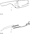
- Figs 6a and 6b the hand held vacuum cleaner 11 and the stick 13 of the stick vacuum cleaner are shown undocked from each other.
Description
- The invention relates to a vacuum cleaner. In particular the invention relates to a stick vacuum cleaner.
- Hand held vacuum cleaners which are battery powered as well as powered by mains supply, are previously known, see for instance
US 4967443 , and are used for fast cleaning of small surfaces. It is important that such vacuum cleaners are easily accessible and user friendly designed. These vacuum cleaners are usually designed such that the dust container together with the filter can be removed from the remaining part of the vacuum cleaner housing that contains the fan unit. - It is also previously known to use the type of hand held vacuum cleaner described above in combination with a shaft part whose, lower portion supports a nozzle. This type of hand held vacuum cleaner can be referred to as a stick vacuum cleaner or a 2-in-1 stick vacuum cleaner, see for instance
WO 2004/069021 . The shaft part is provided with a tube connection by means of which dust laden air is transferred from the nozzle to the air inlet of the hand held vacuum cleaner which is removably secured to the shaft part. This means that the combined stick vacuum cleaner in a comfortable way can be used for floor cleaning purpose. In other words, the handheld stick vacuum cleaner can be docked and undocked to/from the stick to allow for floor cleaning when the hand held vacuum cleaner is docked to the stick. Another conventional stick vacuum cleaner is described inWO2008/088278 . -
US2008040883A discloses a vacuum cleaner having a handle with a handle air passage, a base attached to a first end of the handle by an articulating joint and having a base inlet positioned to face a surface to be cleaned, a base air passage extending from the base inlet and past the articulated joint by a flexible hose and to the handle air passage, a dirt collection assembly associated with the handle and in fluid communication with the handle air passage, a fan associated with the handle and in fluid communication with the handle air passage, and a motor associated with the handle and adapted to drive the fan to thereby generate an airflow through the base inlet, flexible hose, handle air passage, and dirt collection assembly. - In
EP1190660A2 an improved versatile vacuum cleaner is disclosed which comprises a main body, a socket, a first cleaner, a second cleaner, a motor assembly, a cord reel, a handle, and an exhaust duct, and can be converted easily into different configurations each suitable for a specifically different type of vacuum cleaning operation. -
US2002092123A discloses a vacuum cleaner with noise suppression features. The vacuum cleaner comprises a cyclonic airflow chamber that facilitates the separation of contaminants from a suction airstream. The airflow chamber includes a chamber inlet and a chamber outlet, with the chamber inlet being fluidically connected with at least one of a suction nozzle and an above-the- floor cleaning tool. An exhaust filter housing includes a suction duct and an exhaust plenum, with the suction duct communicating with the chamber outlet. - In a conventional stick vacuum cleaner there are strict space requirements. This reduces the possibilities to provide components requiring a large space in the stick vacuum cleaner resulting to worse performance in some aspects compared to conventional vacuum cleaners because some conventional components may have to be omitted or replaced with a less efficient component in a handheld vacuum cleaner. There is a constant desire to improve the performance of vacuum cleaners. Hence there is a need for an improved stick vacuum cleaner.
- It is an object of the present invention to provide an improved vacuum cleaner. In particular it is an object of the present invention to provide an improved stick vacuum cleaner.
- This object is obtained by the stick vacuum cleaner as set out in the appended claims.
- In accordance with one embodiment a stick vacuum cleaner comprising a handheld vacuum cleaner adapted to be docked to a stick is provided. When the handheld vacuum cleaner is docked to the stick an air path is formed connecting an air outlet of the handheld vacuum cleaner with an air outlet provided in the stick. A noise absorption unit is provided in the air path. Hereby the noise is reduced from the vacuum cleaner when configured in a docked mode of operation. The noise absorption unit can as an alternative or as a supplement be provided on the outside of the stick at the air outlet from the stick.
- In accordance with one embodiment an air tight sealing is provided at the air inlet in the stick or at the air outlet from the handheld vacuum cleaner or both at the air inlet in the stick and at the air outlet. The air tight sealing can be sound proof. In accordance with one embodiment the sound proof sealing is U-shaped.
- In accordance with one embodiment the noise absorption unit comprises a muffler. The muffler can be formed by an inner tube and an outer tube having an absorber material placed therein-between.
- In accordance with one embodiment a channel formed by the inner tube is given a cross section of at least 2 cm.
- The invention also extends to a stick for use in a vacuum cleaner in accordance with the above.
- The invention will now be described in more detail, by way of example, and with reference to the accompanying drawings, in which:
-
Figure 1 shows a stick vacuum cleaner according to the prior art; -
Figures 2 and 3 show a sectional view of a stick vacuum cleaner in different embodiments, -
Figure 4 shows a muffler, -
Figure 5 shows a sound proof sealing, and -
Figures 6a and 6b shows a stick vacuum cleaner in an un-docked configuration. - The invention will now be described more fully hereinafter with reference to the accompanying drawings, in which certain embodiments of the invention are shown. The invention may, however, be embodied in many different forms and should not be construed as limited to the embodiments set forth herein; rather, these embodiments are provided by way of example so that this disclosure will be thorough and complete, and will fully convey the scope of the invention to those skilled in the art. Like numbers refer to like elements throughout the description.
-
Figure 1 schematically shows a conventionalstick vacuum cleaner 10 according to the prior art. The shownstick vacuum cleaner 10 comprises an elongated shaft part. The elongated shaft part can be referred to as the stick. In the stick a hand heldvacuum cleaner 11 is removably arranged. Thus the hand held vacuum cleaner can thereby be docked and un-docked to/from the stick. The lower end of the stick supports afloor nozzle 12 that can be turnably secured to the stick. The nozzle has an elongated suction opening and the suction opening is via apassage 15 connected to the hand heldvacuum cleaner 11 in a conventional manner. The upper portion of the stick can be shaped as ahandle 16 and typically has anoperating knob 17 that via an electric circuit, not shown in detail, is connected to the hand heldvacuum cleaner 11 when it is docked to the stick. - A problem associated with a stick vacuum cleaner such as the one depicted in
Fig. 1 is that there are strict space limitations for providing devices inside thehandheld vacuum cleaner 11. This is because there are typically strict requirements as to the size and weight of the handheld vacuum cleaner to not make it bulky and difficult to operate. As a result, some elements are typically omitted or made very small in the handheld vacuum cleaner. For example, there is typically no noise absorption unit provided in the handheld vacuum cleaner or such a noise absorption unit is made very small and does not provide efficient noise reduction. - In order to at least partly solve or reduce this problem, a noise absorption unit can be located in the stick in an air passage way from the air outlet of the
handheld vacuum cleaner 11 to the air outlet from thestick 13. Hereby it is achieved that an improved noise reduction can be provided when the stick vacuum cleaner is in a docked mode where the handheld vacuum cleaner is docked to the stick. The noise absorption unit can as an alternative or as a supplement be provided on the outside of the stick at the air outlet from the stick. - In
Fig. 2 a sectional view from the side of astick vacuum cleaner 10 is shown. InFig. 2 astick 13 of thestick vacuum cleaner 10 is provided with anoise absorption unit 20. Thenoise absorption unit 20 can be located in the air path from thehandheld vacuum cleaner 11 in thestick 13. InFig. 2 the air path is illustrated by thearrow 28. Thus, thenoise absorption unit 20 can be located in the air path from theair outlet 21 of thehandheld vacuum cleaner 11 to anair outlet 22 from thestick 13. When in use, amotor 14 of thehandheld vacuum cleaner 11 draw air from thenozzle 12 via theair passage 15 and out from thehandheld vacuum cleaner 11 via theair outlet 21. If thehandheld vacuum cleaner 11 is docked to thestick 13 the outlet air continues via theair path 28 to theair outlet 22 in thestick 13. - In order to make the noise reduction efficient an air tight sealing can be provided at the air inlet in the stick or the
air outlet 21 from the handheld vacuum cleaner or both. - Further, in
Fig. 2 the noise absorption unit is shown as directly connecting theair outlet 21 with theair outlet 22. However, it is also envisaged that an air path is provided inside the stick directing outlet air from the handheld vacuum cleaner to an air outlet provided in the stick. Thenoise absorption unit 20 can be formed by a container of loosely packed sound absorbing material such as wool. - In
Fig. 3 a sectional view from the side of astick vacuum cleaner 10 in accordance with another embodiment is shown. The embodiment inFig. 3 is similar to the embodiment shown inFig. 2 and has a noise absorption unit formed as amuffler 30. Themuffler 30 can be connected to theair outlet 21 from the hand held vacuum cleaner via a connection having a sound proof sealing 40. - As is shown in
Fig. 4 , themuffler 30 can be a tube composed of anouter tube 31, an innerperforated tube 32 and in the middle anabsorber material 33 can be provided. In accordance with some embodiments, at least one of thetubes inner tubes absorber material 33 can typically be a cushioning material formed by wool, dense cotton fibers, foam, or a similar material. Themuffler 30 will form achannel 34 with a cross section where air can pass to be let out from the stick vacuum cleaner. The design of the cross section area of thechannel 34 will impact the performance of the air flow from thestick vacuum cleaner 10. For example, a small cross section will give rise to higher losses. It is therefore advantageous to provide a muffler with a channel having a cross section more than 2 cm and preferably more than 3 cm. Theair outlet 22 from the stick vacuum cleaner located at the outlet end of themuffler 30 can be provided with a perforated cover and with adiffusor 45. - In
Fig. 5 , a view of a sound proof sealing 40 is shown. The sound proof sealing can be a U-shaped sealing or in some instances a V-shaped sealing. A sound proof sealing is more demanding than having an air-tight sealing. By providing the sealing in a U shape insulation is improved thereby reducing sound. - In
Figs 6a and 6b the hand heldvacuum cleaner 11 and thestick 13 of the stick vacuum cleaner are shown undocked from each other. - The invention has been described above with reference to a few embodiments. However, as is readily appreciated by a person skilled in the art, other embodiments than the ones disclosed above are equally possible within the scope of the invention, as defined by the appended claims.
Claims (9)
- A stick vacuum cleaner (10) comprising a handheld vacuum cleaner (11) and a stick (13), wherein when the handheld vacuum cleaner (11) is docked to the stick (13) an air path (28) is formed connecting an air outlet (21) of the handheld vacuum cleaner (11) with an air outlet (22) provided in the stick (13), characterized in that a noise absorption unit (20) is provided in the air path (28) or outside the air outlet (22) from the stick (13).
- The stick vacuum cleaner (10) according to claim 1, wherein an air tight sealing (40) is provided at the air inlet in the stick or at the air outlet (21) from the handheld vacuum cleaner or both at the air inlet in the stick and at the air outlet (21).
- The stick vacuum cleaner (10) according to claim 2, wherein the air tight sealing (40) is sound proof.
- The stick vacuum cleaner (10) according to claim 3, wherein the sound proof sealing (40) is U-shaped.
- The stick vacuum cleaner (10) according to any one of claims 1 - 4, wherein the noise absorption unit (20) comprises a muffler (30).
- The stick vacuum cleaner (10) according to claim 5, wherein the muffler (30) is formed by an inner tube (31) and an outer tube (32) having an absorber material (33) placed therein-between.
- The stick vacuum cleaner (10) according to claim 6, wherein a channel formed by the inner tube (31) has a cross section of at least 2 cm.
- The stick vacuum cleaner (10) according to any one of claims 1 - 7, wherein a noise absorption unit (20) is provided both in the air path (28) and outside the air outlet (22) provided in the stick (13).
- A stick (13) for receiving a handheld vacuum cleaner (11) adapted to be docked to the stick (13), the stick (13) comprising an air path (28) in one end connected to an air outlet (22) from the stick (13) and in the other end connectable to an air outlet (21) from the handheld vacuum cleaner (11) characterized in that a noise absorption unit (20) is provided in the air path (28) or outside the air outlet (22) from the stick (13).
Applications Claiming Priority (1)
| Application Number | Priority Date | Filing Date | Title |
|---|---|---|---|
| PCT/EP2016/074054 WO2018065069A1 (en) | 2016-10-07 | 2016-10-07 | Low noise stick vaccum cleaner |
Publications (2)
| Publication Number | Publication Date |
|---|---|
| EP3522762A1 EP3522762A1 (en) | 2019-08-14 |
| EP3522762B1 true EP3522762B1 (en) | 2022-08-10 |
Family
ID=57104043
Family Applications (1)
| Application Number | Title | Priority Date | Filing Date |
|---|---|---|---|
| EP16778053.5A Active EP3522762B1 (en) | 2016-10-07 | 2016-10-07 | Low noise stick vaccum cleaner |
Country Status (6)
| Country | Link |
|---|---|
| US (1) | US11350807B2 (en) |
| EP (1) | EP3522762B1 (en) |
| JP (1) | JP6922975B2 (en) |
| KR (1) | KR20190064581A (en) |
| CN (1) | CN109843132B (en) |
| WO (1) | WO2018065069A1 (en) |
Families Citing this family (5)
| Publication number | Priority date | Publication date | Assignee | Title |
|---|---|---|---|---|
| DE212019000449U1 (en) * | 2018-12-13 | 2021-07-21 | Koki Holdings Co., Ltd. | cleanser |
| US20220273146A1 (en) * | 2019-07-08 | 2022-09-01 | Aktiebolaget Electrolux | Handheld vacuum cleaner, and vacuum cleaner comprising a handheld vacuum cleaner |
| USD937513S1 (en) | 2019-09-16 | 2021-11-30 | Techtronic Cordless Gp | Floor cleaner |
| WO2021138122A1 (en) | 2020-01-03 | 2021-07-08 | Techtronic Cordless Gp | Adapter for vacuum cleaner assembly |
| USD948817S1 (en) * | 2020-06-02 | 2022-04-12 | Fine Dragon Technology Limited | Handheld vacuum cleaner |
Family Cites Families (15)
| Publication number | Priority date | Publication date | Assignee | Title |
|---|---|---|---|---|
| US2342905A (en) * | 1934-05-24 | 1944-02-29 | Hoover Co | Suction cleaner |
| US4967443A (en) | 1989-01-09 | 1990-11-06 | Black & Decker, Inc. | Filter assembly for a vacuum cleaner |
| US6158082A (en) * | 1998-03-10 | 2000-12-12 | The Toro Company | Portable blower with blower tube noise reduction |
| KR100389289B1 (en) * | 2000-09-22 | 2003-06-27 | 주식회사 대우일렉트로닉스 | Vacuum cleaner |
| US6532621B2 (en) | 2001-01-12 | 2003-03-18 | Royal Appliance Mfg. Co. | Vacuum cleaner with noise suppression features |
| SE0300355D0 (en) | 2003-02-10 | 2003-02-10 | Electrolux Ab | Hand held vacuum cleaner |
| US20070136984A1 (en) * | 2005-12-15 | 2007-06-21 | Zweita International Co., Ltd. | Rechargeable vacuum cleaner |
| US20080040883A1 (en) | 2006-04-10 | 2008-02-21 | Jonas Beskow | Air Flow Losses in a Vacuum Cleaners |
| SE531125C2 (en) | 2007-01-19 | 2008-12-23 | Electrolux Ab | Improvements in air flow losses in a vacuum cleaner |
| CN203314885U (en) | 2013-05-07 | 2013-12-04 | 宁波伊德尔新材料有限公司 | Silencing dust collector |
| CN203314887U (en) | 2013-06-03 | 2013-12-04 | 苏州市春菊电器有限公司 | Vacuum cleaner with denoising and decorating structure |
| EP2929820B1 (en) * | 2014-04-11 | 2018-09-12 | Black & Decker Inc. | A vacuum cleaning device |
| US10123671B2 (en) * | 2014-05-22 | 2018-11-13 | The Boeing Company | Hand-held pneumatic vacuum |
| US9439548B2 (en) * | 2014-10-16 | 2016-09-13 | Techtronic Industries Co. Ltd. | Battery removal for a vacuum cleaner |
| CN104688136A (en) * | 2015-03-05 | 2015-06-10 | 苏州嘉锐朋电器有限公司 | Dust collector air outlet noise reduction, sterilization and deodorization device |
-
2016
- 2016-10-07 WO PCT/EP2016/074054 patent/WO2018065069A1/en unknown
- 2016-10-07 EP EP16778053.5A patent/EP3522762B1/en active Active
- 2016-10-07 CN CN201680089728.3A patent/CN109843132B/en active Active
- 2016-10-07 KR KR1020197009592A patent/KR20190064581A/en active IP Right Grant
- 2016-10-07 US US16/336,170 patent/US11350807B2/en active Active
- 2016-10-07 JP JP2019510449A patent/JP6922975B2/en active Active
Also Published As
| Publication number | Publication date |
|---|---|
| CN109843132B (en) | 2021-09-10 |
| KR20190064581A (en) | 2019-06-10 |
| US11350807B2 (en) | 2022-06-07 |
| US20200154964A1 (en) | 2020-05-21 |
| JP2019528829A (en) | 2019-10-17 |
| EP3522762A1 (en) | 2019-08-14 |
| JP6922975B2 (en) | 2021-08-18 |
| CN109843132A (en) | 2019-06-04 |
| WO2018065069A1 (en) | 2018-04-12 |
Similar Documents
| Publication | Publication Date | Title |
|---|---|---|
| EP3522762B1 (en) | Low noise stick vaccum cleaner | |
| KR101821908B1 (en) | Electric vacuum cleaner | |
| EP3209175B1 (en) | Handheld vacuum cleaner | |
| US8397344B2 (en) | Cleaning appliance | |
| WO2017181484A1 (en) | Hand-hold vacuum cleaner | |
| CN110074718B (en) | Hand-held dust collector | |
| JP6291218B2 (en) | Electric vacuum cleaner | |
| CN105935275A (en) | Cyclone type dust collector with transverse dust barrel | |
| US7647670B2 (en) | Vacuum cleaner with final filtration compartment for reducing noise | |
| EP3522761B1 (en) | Stick vacuum cleaner with improved filter | |
| KR20150109903A (en) | Vacuum cleaner | |
| CN111588303B (en) | Dust collector | |
| EP2789282A1 (en) | Electric vacuum cleaner | |
| CN212937572U (en) | Mite removing instrument | |
| JP5357980B2 (en) | Vertical vacuum cleaner | |
| JP6178214B2 (en) | Electric vacuum cleaner | |
| JP2014138639A (en) | Vacuum cleaner | |
| JP2020000562A (en) | Suction port body of vacuum cleaner and vacuum cleaner with the suction port body | |
| KR20110009856U (en) | Vacuum cleaner | |
| JP2001238829A (en) | Electric vacuum cleaner | |
| CN101147662A (en) | Vacuum cleaner dust-gathering cartridge | |
| KR20070068937A (en) | Vacuum cleaner |
Legal Events
| Date | Code | Title | Description |
|---|---|---|---|
| STAA | Information on the status of an ep patent application or granted ep patent |
Free format text: STATUS: UNKNOWN |
|
| STAA | Information on the status of an ep patent application or granted ep patent |
Free format text: STATUS: THE INTERNATIONAL PUBLICATION HAS BEEN MADE |
|
| PUAI | Public reference made under article 153(3) epc to a published international application that has entered the european phase |
Free format text: ORIGINAL CODE: 0009012 |
|
| STAA | Information on the status of an ep patent application or granted ep patent |
Free format text: STATUS: REQUEST FOR EXAMINATION WAS MADE |
|
| 17P | Request for examination filed |
Effective date: 20190507 |
|
| AK | Designated contracting states |
Kind code of ref document: A1 Designated state(s): AL AT BE BG CH CY CZ DE DK EE ES FI FR GB GR HR HU IE IS IT LI LT LU LV MC MK MT NL NO PL PT RO RS SE SI SK SM TR |
|
| AX | Request for extension of the european patent |
Extension state: BA ME |
|
| DAV | Request for validation of the european patent (deleted) | ||
| DAX | Request for extension of the european patent (deleted) | ||
| GRAP | Despatch of communication of intention to grant a patent |
Free format text: ORIGINAL CODE: EPIDOSNIGR1 |
|
| STAA | Information on the status of an ep patent application or granted ep patent |
Free format text: STATUS: GRANT OF PATENT IS INTENDED |
|
| INTG | Intention to grant announced |
Effective date: 20220405 |
|
| GRAS | Grant fee paid |
Free format text: ORIGINAL CODE: EPIDOSNIGR3 |
|
| GRAA | (expected) grant |
Free format text: ORIGINAL CODE: 0009210 |
|
| STAA | Information on the status of an ep patent application or granted ep patent |
Free format text: STATUS: THE PATENT HAS BEEN GRANTED |
|
| AK | Designated contracting states |
Kind code of ref document: B1 Designated state(s): AL AT BE BG CH CY CZ DE DK EE ES FI FR GB GR HR HU IE IS IT LI LT LU LV MC MK MT NL NO PL PT RO RS SE SI SK SM TR |
|
| REG | Reference to a national code |
Ref country code: AT Ref legal event code: REF Ref document number: 1509891 Country of ref document: AT Kind code of ref document: T Effective date: 20220815 Ref country code: CH Ref legal event code: EP |
|
| REG | Reference to a national code |
Ref country code: DE Ref legal event code: R096 Ref document number: 602016074162 Country of ref document: DE |
|
| REG | Reference to a national code |
Ref country code: IE Ref legal event code: FG4D |
|
| REG | Reference to a national code |
Ref country code: LT Ref legal event code: MG9D |
|
| PGFP | Annual fee paid to national office [announced via postgrant information from national office to epo] |
Ref country code: FR Payment date: 20221031 Year of fee payment: 7 |
|
| PG25 | Lapsed in a contracting state [announced via postgrant information from national office to epo] |
Ref country code: SE Free format text: LAPSE BECAUSE OF FAILURE TO SUBMIT A TRANSLATION OF THE DESCRIPTION OR TO PAY THE FEE WITHIN THE PRESCRIBED TIME-LIMIT Effective date: 20220810 Ref country code: RS Free format text: LAPSE BECAUSE OF FAILURE TO SUBMIT A TRANSLATION OF THE DESCRIPTION OR TO PAY THE FEE WITHIN THE PRESCRIBED TIME-LIMIT Effective date: 20220810 Ref country code: PT Free format text: LAPSE BECAUSE OF FAILURE TO SUBMIT A TRANSLATION OF THE DESCRIPTION OR TO PAY THE FEE WITHIN THE PRESCRIBED TIME-LIMIT Effective date: 20221212 Ref country code: NO Free format text: LAPSE BECAUSE OF FAILURE TO SUBMIT A TRANSLATION OF THE DESCRIPTION OR TO PAY THE FEE WITHIN THE PRESCRIBED TIME-LIMIT Effective date: 20221110 Ref country code: NL Free format text: LAPSE BECAUSE OF FAILURE TO SUBMIT A TRANSLATION OF THE DESCRIPTION OR TO PAY THE FEE WITHIN THE PRESCRIBED TIME-LIMIT Effective date: 20220810 Ref country code: LV Free format text: LAPSE BECAUSE OF FAILURE TO SUBMIT A TRANSLATION OF THE DESCRIPTION OR TO PAY THE FEE WITHIN THE PRESCRIBED TIME-LIMIT Effective date: 20220810 Ref country code: LT Free format text: LAPSE BECAUSE OF FAILURE TO SUBMIT A TRANSLATION OF THE DESCRIPTION OR TO PAY THE FEE WITHIN THE PRESCRIBED TIME-LIMIT Effective date: 20220810 Ref country code: FI Free format text: LAPSE BECAUSE OF FAILURE TO SUBMIT A TRANSLATION OF THE DESCRIPTION OR TO PAY THE FEE WITHIN THE PRESCRIBED TIME-LIMIT Effective date: 20220810 |
|
| PGFP | Annual fee paid to national office [announced via postgrant information from national office to epo] |
Ref country code: GB Payment date: 20221020 Year of fee payment: 7 Ref country code: DE Payment date: 20221019 Year of fee payment: 7 |
|
| REG | Reference to a national code |
Ref country code: AT Ref legal event code: MK05 Ref document number: 1509891 Country of ref document: AT Kind code of ref document: T Effective date: 20220810 |
|
| PG25 | Lapsed in a contracting state [announced via postgrant information from national office to epo] |
Ref country code: PL Free format text: LAPSE BECAUSE OF FAILURE TO SUBMIT A TRANSLATION OF THE DESCRIPTION OR TO PAY THE FEE WITHIN THE PRESCRIBED TIME-LIMIT Effective date: 20220810 Ref country code: IS Free format text: LAPSE BECAUSE OF FAILURE TO SUBMIT A TRANSLATION OF THE DESCRIPTION OR TO PAY THE FEE WITHIN THE PRESCRIBED TIME-LIMIT Effective date: 20221210 Ref country code: HR Free format text: LAPSE BECAUSE OF FAILURE TO SUBMIT A TRANSLATION OF THE DESCRIPTION OR TO PAY THE FEE WITHIN THE PRESCRIBED TIME-LIMIT Effective date: 20220810 Ref country code: GR Free format text: LAPSE BECAUSE OF FAILURE TO SUBMIT A TRANSLATION OF THE DESCRIPTION OR TO PAY THE FEE WITHIN THE PRESCRIBED TIME-LIMIT Effective date: 20221111 |
|
| PG25 | Lapsed in a contracting state [announced via postgrant information from national office to epo] |
Ref country code: SM Free format text: LAPSE BECAUSE OF FAILURE TO SUBMIT A TRANSLATION OF THE DESCRIPTION OR TO PAY THE FEE WITHIN THE PRESCRIBED TIME-LIMIT Effective date: 20220810 Ref country code: RO Free format text: LAPSE BECAUSE OF FAILURE TO SUBMIT A TRANSLATION OF THE DESCRIPTION OR TO PAY THE FEE WITHIN THE PRESCRIBED TIME-LIMIT Effective date: 20220810 Ref country code: ES Free format text: LAPSE BECAUSE OF FAILURE TO SUBMIT A TRANSLATION OF THE DESCRIPTION OR TO PAY THE FEE WITHIN THE PRESCRIBED TIME-LIMIT Effective date: 20220810 Ref country code: DK Free format text: LAPSE BECAUSE OF FAILURE TO SUBMIT A TRANSLATION OF THE DESCRIPTION OR TO PAY THE FEE WITHIN THE PRESCRIBED TIME-LIMIT Effective date: 20220810 Ref country code: CZ Free format text: LAPSE BECAUSE OF FAILURE TO SUBMIT A TRANSLATION OF THE DESCRIPTION OR TO PAY THE FEE WITHIN THE PRESCRIBED TIME-LIMIT Effective date: 20220810 Ref country code: AT Free format text: LAPSE BECAUSE OF FAILURE TO SUBMIT A TRANSLATION OF THE DESCRIPTION OR TO PAY THE FEE WITHIN THE PRESCRIBED TIME-LIMIT Effective date: 20220810 |
|
| REG | Reference to a national code |
Ref country code: DE Ref legal event code: R097 Ref document number: 602016074162 Country of ref document: DE |
|
| PG25 | Lapsed in a contracting state [announced via postgrant information from national office to epo] |
Ref country code: SK Free format text: LAPSE BECAUSE OF FAILURE TO SUBMIT A TRANSLATION OF THE DESCRIPTION OR TO PAY THE FEE WITHIN THE PRESCRIBED TIME-LIMIT Effective date: 20220810 Ref country code: MC Free format text: LAPSE BECAUSE OF FAILURE TO SUBMIT A TRANSLATION OF THE DESCRIPTION OR TO PAY THE FEE WITHIN THE PRESCRIBED TIME-LIMIT Effective date: 20220810 Ref country code: EE Free format text: LAPSE BECAUSE OF FAILURE TO SUBMIT A TRANSLATION OF THE DESCRIPTION OR TO PAY THE FEE WITHIN THE PRESCRIBED TIME-LIMIT Effective date: 20220810 |
|
| REG | Reference to a national code |
Ref country code: CH Ref legal event code: PL |
|
| PLBE | No opposition filed within time limit |
Free format text: ORIGINAL CODE: 0009261 |
|
| STAA | Information on the status of an ep patent application or granted ep patent |
Free format text: STATUS: NO OPPOSITION FILED WITHIN TIME LIMIT |
|
| REG | Reference to a national code |
Ref country code: BE Ref legal event code: MM Effective date: 20221031 |
|
| P01 | Opt-out of the competence of the unified patent court (upc) registered |
Effective date: 20230521 |
|
| PG25 | Lapsed in a contracting state [announced via postgrant information from national office to epo] |
Ref country code: LU Free format text: LAPSE BECAUSE OF NON-PAYMENT OF DUE FEES Effective date: 20221007 Ref country code: AL Free format text: LAPSE BECAUSE OF FAILURE TO SUBMIT A TRANSLATION OF THE DESCRIPTION OR TO PAY THE FEE WITHIN THE PRESCRIBED TIME-LIMIT Effective date: 20220810 |
|
| 26N | No opposition filed |
Effective date: 20230511 |
|
| PG25 | Lapsed in a contracting state [announced via postgrant information from national office to epo] |
Ref country code: LI Free format text: LAPSE BECAUSE OF NON-PAYMENT OF DUE FEES Effective date: 20221031 Ref country code: CH Free format text: LAPSE BECAUSE OF NON-PAYMENT OF DUE FEES Effective date: 20221031 |
|
| PG25 | Lapsed in a contracting state [announced via postgrant information from national office to epo] |
Ref country code: SI Free format text: LAPSE BECAUSE OF FAILURE TO SUBMIT A TRANSLATION OF THE DESCRIPTION OR TO PAY THE FEE WITHIN THE PRESCRIBED TIME-LIMIT Effective date: 20220810 |
|
| PG25 | Lapsed in a contracting state [announced via postgrant information from national office to epo] |
Ref country code: BE Free format text: LAPSE BECAUSE OF NON-PAYMENT OF DUE FEES Effective date: 20221031 |
|
| PG25 | Lapsed in a contracting state [announced via postgrant information from national office to epo] |
Ref country code: IE Free format text: LAPSE BECAUSE OF NON-PAYMENT OF DUE FEES Effective date: 20221007 |
|
| PG25 | Lapsed in a contracting state [announced via postgrant information from national office to epo] |
Ref country code: HU Free format text: LAPSE BECAUSE OF FAILURE TO SUBMIT A TRANSLATION OF THE DESCRIPTION OR TO PAY THE FEE WITHIN THE PRESCRIBED TIME-LIMIT; INVALID AB INITIO Effective date: 20161007 |