EP3522555B1 - Wireless transmitter receiver and vehicle - Google Patents
Wireless transmitter receiver and vehicle Download PDFInfo
- Publication number
- EP3522555B1 EP3522555B1 EP17869438.6A EP17869438A EP3522555B1 EP 3522555 B1 EP3522555 B1 EP 3522555B1 EP 17869438 A EP17869438 A EP 17869438A EP 3522555 B1 EP3522555 B1 EP 3522555B1
- Authority
- EP
- European Patent Office
- Prior art keywords
- communication device
- data
- collection device
- data collection
- notification signal
- Prior art date
- Legal status (The legal status is an assumption and is not a legal conclusion. Google has not performed a legal analysis and makes no representation as to the accuracy of the status listed.)
- Active
Links
Images



Classifications
-
- H—ELECTRICITY
- H04—ELECTRIC COMMUNICATION TECHNIQUE
- H04W—WIRELESS COMMUNICATION NETWORKS
- H04W68/00—User notification, e.g. alerting and paging, for incoming communication, change of service or the like
- H04W68/005—Transmission of information for alerting of incoming communication
-
- H—ELECTRICITY
- H04—ELECTRIC COMMUNICATION TECHNIQUE
- H04L—TRANSMISSION OF DIGITAL INFORMATION, e.g. TELEGRAPHIC COMMUNICATION
- H04L67/00—Network arrangements or protocols for supporting network services or applications
- H04L67/01—Protocols
- H04L67/12—Protocols specially adapted for proprietary or special-purpose networking environments, e.g. medical networks, sensor networks, networks in vehicles or remote metering networks
-
- B—PERFORMING OPERATIONS; TRANSPORTING
- B60—VEHICLES IN GENERAL
- B60N—SEATS SPECIALLY ADAPTED FOR VEHICLES; VEHICLE PASSENGER ACCOMMODATION NOT OTHERWISE PROVIDED FOR
- B60N3/00—Arrangements or adaptations of other passenger fittings, not otherwise provided for
- B60N3/14—Arrangements or adaptations of other passenger fittings, not otherwise provided for of electrically-heated lighters
-
- B—PERFORMING OPERATIONS; TRANSPORTING
- B60—VEHICLES IN GENERAL
- B60R—VEHICLES, VEHICLE FITTINGS, OR VEHICLE PARTS, NOT OTHERWISE PROVIDED FOR
- B60R16/00—Electric or fluid circuits specially adapted for vehicles and not otherwise provided for; Arrangement of elements of electric or fluid circuits specially adapted for vehicles and not otherwise provided for
- B60R16/02—Electric or fluid circuits specially adapted for vehicles and not otherwise provided for; Arrangement of elements of electric or fluid circuits specially adapted for vehicles and not otherwise provided for electric constitutive elements
-
- B—PERFORMING OPERATIONS; TRANSPORTING
- B60—VEHICLES IN GENERAL
- B60R—VEHICLES, VEHICLE FITTINGS, OR VEHICLE PARTS, NOT OTHERWISE PROVIDED FOR
- B60R16/00—Electric or fluid circuits specially adapted for vehicles and not otherwise provided for; Arrangement of elements of electric or fluid circuits specially adapted for vehicles and not otherwise provided for
- B60R16/02—Electric or fluid circuits specially adapted for vehicles and not otherwise provided for; Arrangement of elements of electric or fluid circuits specially adapted for vehicles and not otherwise provided for electric constitutive elements
- B60R16/03—Electric or fluid circuits specially adapted for vehicles and not otherwise provided for; Arrangement of elements of electric or fluid circuits specially adapted for vehicles and not otherwise provided for electric constitutive elements for supply of electrical power to vehicle subsystems or for
- B60R16/033—Electric or fluid circuits specially adapted for vehicles and not otherwise provided for; Arrangement of elements of electric or fluid circuits specially adapted for vehicles and not otherwise provided for electric constitutive elements for supply of electrical power to vehicle subsystems or for characterised by the use of electrical cells or batteries
-
- G—PHYSICS
- G01—MEASURING; TESTING
- G01N—INVESTIGATING OR ANALYSING MATERIALS BY DETERMINING THEIR CHEMICAL OR PHYSICAL PROPERTIES
- G01N17/00—Investigating resistance of materials to the weather, to corrosion, or to light
-
- G—PHYSICS
- G08—SIGNALLING
- G08C—TRANSMISSION SYSTEMS FOR MEASURED VALUES, CONTROL OR SIMILAR SIGNALS
- G08C15/00—Arrangements characterised by the use of multiplexing for the transmission of a plurality of signals over a common path
-
- H—ELECTRICITY
- H04—ELECTRIC COMMUNICATION TECHNIQUE
- H04Q—SELECTING
- H04Q9/00—Arrangements in telecontrol or telemetry systems for selectively calling a substation from a main station, in which substation desired apparatus is selected for applying a control signal thereto or for obtaining measured values therefrom
-
- H—ELECTRICITY
- H04—ELECTRIC COMMUNICATION TECHNIQUE
- H04W—WIRELESS COMMUNICATION NETWORKS
- H04W4/00—Services specially adapted for wireless communication networks; Facilities therefor
- H04W4/30—Services specially adapted for particular environments, situations or purposes
- H04W4/38—Services specially adapted for particular environments, situations or purposes for collecting sensor information
-
- H—ELECTRICITY
- H04—ELECTRIC COMMUNICATION TECHNIQUE
- H04W—WIRELESS COMMUNICATION NETWORKS
- H04W4/00—Services specially adapted for wireless communication networks; Facilities therefor
- H04W4/30—Services specially adapted for particular environments, situations or purposes
- H04W4/40—Services specially adapted for particular environments, situations or purposes for vehicles, e.g. vehicle-to-pedestrians [V2P]
-
- H—ELECTRICITY
- H04—ELECTRIC COMMUNICATION TECHNIQUE
- H04W—WIRELESS COMMUNICATION NETWORKS
- H04W4/00—Services specially adapted for wireless communication networks; Facilities therefor
- H04W4/30—Services specially adapted for particular environments, situations or purposes
- H04W4/40—Services specially adapted for particular environments, situations or purposes for vehicles, e.g. vehicle-to-pedestrians [V2P]
- H04W4/48—Services specially adapted for particular environments, situations or purposes for vehicles, e.g. vehicle-to-pedestrians [V2P] for in-vehicle communication
-
- H—ELECTRICITY
- H04—ELECTRIC COMMUNICATION TECHNIQUE
- H04W—WIRELESS COMMUNICATION NETWORKS
- H04W52/00—Power management, e.g. Transmission Power Control [TPC] or power classes
- H04W52/02—Power saving arrangements
- H04W52/0209—Power saving arrangements in terminal devices
- H04W52/0225—Power saving arrangements in terminal devices using monitoring of external events, e.g. the presence of a signal
- H04W52/0229—Power saving arrangements in terminal devices using monitoring of external events, e.g. the presence of a signal where the received signal is a wanted signal
-
- H—ELECTRICITY
- H04—ELECTRIC COMMUNICATION TECHNIQUE
- H04W—WIRELESS COMMUNICATION NETWORKS
- H04W52/00—Power management, e.g. Transmission Power Control [TPC] or power classes
- H04W52/02—Power saving arrangements
- H04W52/0209—Power saving arrangements in terminal devices
- H04W52/0261—Power saving arrangements in terminal devices managing power supply demand, e.g. depending on battery level
- H04W52/0274—Power saving arrangements in terminal devices managing power supply demand, e.g. depending on battery level by switching on or off the equipment or parts thereof
- H04W52/028—Power saving arrangements in terminal devices managing power supply demand, e.g. depending on battery level by switching on or off the equipment or parts thereof switching on or off only a part of the equipment circuit blocks
-
- H—ELECTRICITY
- H04—ELECTRIC COMMUNICATION TECHNIQUE
- H04W—WIRELESS COMMUNICATION NETWORKS
- H04W52/00—Power management, e.g. Transmission Power Control [TPC] or power classes
- H04W52/02—Power saving arrangements
- H04W52/0209—Power saving arrangements in terminal devices
- H04W52/0225—Power saving arrangements in terminal devices using monitoring of external events, e.g. the presence of a signal
- H04W52/0229—Power saving arrangements in terminal devices using monitoring of external events, e.g. the presence of a signal where the received signal is a wanted signal
- H04W52/0235—Power saving arrangements in terminal devices using monitoring of external events, e.g. the presence of a signal where the received signal is a wanted signal where the received signal is a power saving command
Definitions
- the technique disclosed herein relates to a wireless transmitting and receiving device and a vehicle including a plurality of devices that can communicate with each other.
- Patent Literature 1 At a development site of a vehicle, many sensors may be attached to various parts of the vehicle (see Patent Literature 1). Since the sensors of Patent Literature 1 are connected to a data collection device with signal lines, a worker needs to spend a lot of effort to arrange the signal lines between the sensors and the data collection device.
- Patent Literature 2 proposes a technique for wirelessly communicating data acquired by a sensor to a data collection device. According to the technique of Patent Literature 2, it is not necessary to carry out work to arrange signal lines between the sensor and the data collection device.
- Patent Literatures 1 and 2 do not sufficiently study this point.
- Patent Literature 1 As described in Patent Literature 1 above, at a development site of a vehicle, corrosion sensors are attached to respective parts of the vehicle, detection data output from the corrosion sensors is stored in a data collection device, and the degree of progress of corrosion in respective parts of the vehicle is examined. In this case, it is necessary to store the detection data output from the corrosion sensors even while an engine of the vehicle is stopped. Therefore, it is considered to supply power from an onboard battery to the data collection device. However, when power is supplied from the onboard battery to the data collection device, power loss of the onboard battery (so-called dead battery) may occur, as described in paragraph [0022] of Patent Literature 1. Therefore, in Patent Literature 1, power is supplied from a dedicated battery different from the onboard battery to the data collection device.
- the present inventors have found a configuration that can avoid occurrence of power loss of the onboard battery as much as possible while the dedicated battery is not mounted and power is supplied from the onboard battery to the data collection device.
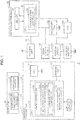
- FIG. 1 is a block diagram schematically showing a configuration of a vehicle including a wireless transmitting and receiving device of the present embodiment.
- the vehicle 1 shown in FIG. 1 is, for example, a four-wheeled vehicle.
- the vehicle 1 includes a wireless transmitter 10, a detector 20, a data collection device 30, an antenna unit 40, an onboard battery 42, an ignition switch 44, a cigar lighter socket 46, a secondary cell 48, and an electronic control unit (ECU) 50.
- ECU electronice control unit
- the vehicle 1 is for evaluating performance of the vehicle using many sensors attached to the vehicle at a development site of a vehicle.
- the detector 20 includes a corrosion sensor 21 and a temperature and humidity sensor 22 as such sensors.
- the corrosion sensor 21 is connected to the wireless transmitter 10 with a connection cable 23, and the temperature and humidity sensor 22 is connected to the wireless transmitter 10 with a connection cable 24.
- the antenna unit 40 is connected to the data collection device 30 with a connection cable 41.
- the vehicle 1 is configured such that detection data of the detector 20 is transmitted wirelessly by the wireless transmitter 10 and is stored in the data collection device 30 via the antenna unit 40.
- the corrosion sensor 21 detects the corrosion degree at a place where the corrosion sensor 21 is attached in the vehicle 1.
- the corrosion sensor 21 may be a general sensor device capable of detecting the degree of corrosion of the vehicle 1.
- an atmospheric corrosion monitor (ACM) type corrosion sensor may be used as the corrosion sensor 21, for example, an atmospheric corrosion monitor (ACM) type corrosion sensor may be used.
- ACM atmospheric corrosion monitor
- the temperature and humidity sensor 22 detects the temperature and humidity at a place where the temperature and humidity sensor 22 is attached in the vehicle 1.
- a general detection device may be used.
- a known platinum resistance thermometer sensor may be used.
- a known polymer capacitive humidity detection device may be used.
- FIG. 2 is a diagram schematically showing an example of arrangement of the wireless transmitters 10, the detectors 20, the data collection device 30, and the antenna unit 40.
- the detectors 20 are attached to, for example, four places of the vehicle 1 including an engine room, a front wheel house, an outer plate of a lift gate, and an undercover of the engine.
- the wireless transmitters 10 connected to the detectors 20 with the connection cables 23 and 24 are attached to four places of the vehicle 1 near the detectors 20.
- the data collection device 30 is disposed, for example, in a trunk room 2 of the vehicle 1.
- the antenna unit 40 is disposed, for example, on a ceiling of an indoor front portion 3 of the vehicle 1.
- the wireless transmitter 10 wirelessly transmits the detection data of the detector 20 to the data collection device 30 (an example of the second communication device).
- the data collection device 30 is also referred to as "master”
- the wireless transmitter 10 is also referred to as "slave.”
- the wireless transmitter 10 includes a memory 11, a central processing unit (CPU) 12, an antenna unit 13, a cell 14, and the like.
- the antenna unit 13 is controlled by the CPU 12, and the antenna unit 13 transmits data and the like by radiating radio waves of a frequency of 2.4 GHz with power of 3 mW in the present embodiment, for example.
- the antenna unit 13 receives a request signal or the like transmitted from the antenna unit 40.
- the cell 14 supplies power for operating the memory 11, the CPU 12, the corrosion sensor 21, and the temperature and humidity sensor 22.
- the memory 11 (an example of the storage) of the wireless transmitter 10 is configured by, for example, a semiconductor memory such as a flash memory, or other storage devices.
- the memory 11 includes a memory for temporarily storing the detection data detected by the detector 20, a memory for storing a program, and the like. Note that the memory 11 may be configured by a single memory device including an area for temporarily storing the detection data detected by the detector 20 and an area for storing a program.
- the detectors 20 and the wireless transmitters 10 are attached to a plurality of places of the vehicle 1 (four places in the present embodiment). Therefore, the memory 11 of each of the four wireless transmitters 10 stores in advance a unique slave ID for identifying each of the wireless transmitters 10.
- the CPU 12 functions as a data controller 120 and a mode controller 12c by operating in accordance with the program stored in the memory 11.
- the data controller 120 functions as a detection controller 12a and a communication controller 12b.
- the detection controller 12a acquires, via the connection cable 23, corrosion data detected by the corrosion sensor 21. The detection controller 12a notifies the communication controller 12b of the acquired corrosion data. The detection controller 12a acquires, via the connection cable 24, temperature data and humidity data detected by the temperature and humidity sensor 22. The detection controller 12a notifies the communication controller 12b of the acquired temperature data and the humidity data.
- the communication controller 12b generates a transmission signal including the detection data notified from the detection controller 12a (corrosion data, temperature data, and humidity data in the present embodiment), the slave ID, and a data sequence number stored in the memory 11.
- the data sequence number may be a serial number indicating sequence from the detection data detected first.
- the communication controller 12b transmits the generated transmission signal from the antenna unit 13.
- the mode controller 12c controls an operation mode of the CPU 12 (the data controller 120).
- the mode controller 12c controls the CPU 12 into a normal mode for performing normal operations and a sleep mode for performing operations of minimum requirement.
- the mode controller 12c first causes the CPU 12 to transition from the normal mode to the sleep mode.
- the mode controller 12c counts elapsed time in the sleep mode, and causes the CPU 12 to transition to the normal mode when a predetermined sampling time elapses.
- the detection controller 12a and the communication controller 12b perform predetermined operations.
- the mode controller 12c causes the CPU 12 to transition to the sleep mode.
- the life of the cell 14 is extended by this mode controller 12c.
- the mode controller 12c causes the CPU 12 to operate in a power on mode when the data collection device 30 is in operation.
- the mode controller 12c causes the CPU 12 to operate in a power off mode when the operation of the data collection device 30 is stopped.
- the sampling time differs between the power on mode and the power off mode. A specific example of the sampling time will be described in detail later.
- the antenna unit 40 receives the transmission signal including the detection data (corrosion data, temperature data, and humidity data in the present embodiment) of the detector 20 by receiving radio waves radiated from the antenna unit 13. As described above, the antenna unit 40 is connected to the data collection device 30 with the connection cable 41.
- the data collection device 30 collects the detection data (corrosion data, temperature data, and humidity data in the present embodiment) of the detector 20.
- the data collection device 30 includes a memory 31, a CPU 32, and other peripheral circuits.
- the data collection device 30 is configured by a personal computer, for example.
- the memory 31 is configured by a semiconductor memory such as a flash memory, a hard disk, or another storage device, for example.
- the memory 31 includes a memory for storing the data detected by the detectors 20, a memory for storing a data collection program, a memory for temporarily storing data, and the like.
- the memory 31 may be configured by a single memory device including an area for storing the data detected by the detectors 20, an area for storing the data collection program, and an area for temporarily storing the data.
- the memory 31 stores in advance each of the slave IDs of each of the wireless transmitters 10.
- the CPU 32 functions as a communication controller 33 by operating in accordance with the data collection program stored in the memory 31.
- the communication controller 33 stores, in the memory 31, the detection data (corrosion data, temperature data, and humidity data in the present embodiment) of the detector 20 received by the antenna unit 40.
- the communication controller 33 (an example of the signal generator) generates an instruction signal instructing a mode change from the power on mode to the power off mode.
- the communication controller 33 controls transmission of the above instruction signal to each of the wireless transmitters 10.
- the communication controller 33 When the ignition switch 44 is turned on after the ignition switch 44 is turned off, the communication controller 33 generates a preparation signal instructing each of the wireless transmitters 10 to prepare data collection. The communication controller 33 controls transmission of the preparation signal to each of the wireless transmitters 10.
- the instruction signal is an example of the stop notification signal notifying that the data collection device 30 in operation stops the operation.
- the preparation signal is an example of the restart notification signal notifying that the data collection device 30 has restarted the operation after the operation stops.
- the onboard battery 42, the ignition switch 44, and the cigar lighter socket 46 are known components mounted on a general vehicle.
- the cigar lighter socket 46 is connected to a positive electrode of the secondary cell 48, and the positive electrode of the secondary cell 48 is connected to the data collection device 30.
- the cigar lighter socket 46 is connected to the onboard battery 42 via the ignition switch 44. Therefore, the onboard battery 42 charges the secondary cell 48 through the cigar lighter socket 46 only while the ignition switch 44 is on (while the engine of the vehicle 1 is operating).
- the secondary cell 48 is configured to supply power to the data collection device 30 regardless of on-off of the ignition switch 44 (that is, an operating state of the engine of the vehicle 1) in the present embodiment.
- the ECU 50 controls the overall operation of the vehicle 1.
- the ECU 50 detects on-off of the ignition switch 44.
- the ECU 50 notifies the CPU 32 (the communication controller 33) of the data collection device 30 of the detected on-off state of the ignition switch 44.
- the CPU 32 (the communication controller 33) of the data collection device 30 determines the on-off state of the ignition switch 44 based on a signal output from the ECU 50.
- the ECU 50 and the CPU 32 of the data collection device 30 may be directly connected wirelessly or with a cable, or may be indirectly connected via another controller (CPU).
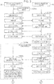
- FIGS. 3 to 5 are sequence diagrams schematically showing one example of the operations of the wireless transmitter 10 (slave) and the data collection device 30 (master).
- step S1000 of FIG. 3 the power of the wireless transmitter 10 is turned on by a user, for example.
- the ignition switch 44 is turned on by the user for example, in step S2000, the power of the data collection device 30 is turned on in step S3000.
- a configuration may be provided in which the power of the data collection device 30 is turned on when the secondary cell 48 is connected to the data collection device 30 by the user and power supply is started from the secondary cell 48 to the data collection device 30.
- a configuration may be provided in which the power of the data collection device 30 is turned on when the power switch provided in the data collection device 30 is turned on by the user.
- step S3010 the communication controller 33 of the data collection device 30 transmits a preparation signal instructing preparation for data collection to each of the wireless transmitters 10 (four wireless transmitters 10 in the present embodiment as shown in FIG. 2 ).
- step S1010 the communication controller 12b of the data controller 120 of each of the wireless transmitters 10 starts preparation for data collection.
- the communication controller 12b transmits, to the data collection device 30, a response signal including the slave ID and a first time signal indicating that this is the first time from power on.
- step S3020 the communication controller 33 of the data collection device 30 checks the response signal including the slave ID and the first time signal transmitted from each of the wireless transmitters 10.
- step S3030 the communication controller 33 of the data collection device 30 transmits a start signal instructing to start to collect data to the wireless transmitter 10 corresponding to the slave ID that has responded.
- the communication controller 12b of the data controller 120 of the wireless transmitter 10 having received the start signal transmits a response signal including the slave ID to the data collection device 30 in step S1030 and notifies the mode controller 12c of the fact that the start signal has been received.
- step S3040 the communication controller 33 of the data collection device 30 checks the response signal transmitted from each of the wireless transmitters 10.
- step S1040 in response to the notification that the start signal has been received, the mode controller 12c causes the CPU 12 to transition to the sleep mode.
- Step S2100 that follows is repeated at predetermined sampling time intervals (at one-minute intervals in the present embodiment, for example) of the power on mode.
- the mode controller 12c causes the CPU 12 to transition to the normal mode.
- the detection controller 12a supplies power from the cell 14 to the corrosion sensor 21 and the temperature and humidity sensor 22 for operation, and acquires the detection data (corrosion data, temperature data, and humidity data) of the detector 20.
- step S1070 the communication controller 12b of the data controller 120 of each of the wireless transmitters 10 transmits the transmission signal including the detection data acquired in step S1060 to the data collection device 30.
- this transmission signal includes the slave ID and the data sequence number in addition to the detection data.
- step S3050 the communication controller 33 of the data collection device 30 receives the transmission signal transmitted from each of the wireless transmitters 10 in step S1070, and temporarily stores the transmission signal in the memory 31.
- step S3060 the communication controller 33 of the data collection device 30 transmits a response signal indicating that the transmission signal has been received to each of the wireless transmitters 10.
- step S1072 the communication controller 12b of the wireless transmitter 10 checks the response signal transmitted from the data collection device 30. After checking the response signal, the mode controller 12c causes the CPU 12 to transition to the sleep mode in step S1080.
- step S3070 the communication controller 33 of the data collection device 30 checks the slave ID and the data sequence number included in the transmission signal received in step S3050. When the slave ID and the data sequence number are all present, the communication controller 33 stores the received detection data in association with the slave ID and the data sequence number, in the memory 31 as normal data. Step S2100 described above is executed at sampling time intervals (at one-minute intervals in the present embodiment, for example) of the power on mode.
- step S2100 described above is executed at sampling time intervals (at one-minute intervals in the present embodiment, for example) of the power on mode.
- the communication controller 33 of the data collection device 30 Upon determination based on an output signal from the ECU 50 that the ignition switch 44 is turned off, the communication controller 33 of the data collection device 30 generates an instruction signal instructing the mode change from the power on mode to the power off mode in step S3100. The data collection device 30 transmits the instruction signal to each of the wireless transmitters 10.
- step S1110 When the wireless transmitter 10 transitions to the normal mode (step S1050) and then receives the instruction signal from the data collection device 30 (step S3100), in step S1110, the mode controller 12c of the wireless transmitter 10 changes the CPU 12 to the power off mode.
- step S1120 the communication controller 12b of the data controller 120 of each of the wireless transmitters 10 transmits, to the data collection device 30, a response signal including the slave ID to the instruction signal of step S3100.
- step S1130 the CPU 12 (the data controller 120) of the wireless transmitter 10 transitions to the sleep mode by the mode controller 12c.
- step S3120 the communication controller 33 of the data collection device 30 checks the response signal transmitted from each of the wireless transmitters 10. Thereafter, in step S3130, the power of the data collection device 30 is turned off.
- a configuration may be provided in which the power of the data collection device 30 is automatically turned off, when the communication controller 33 determines, based on the output signal from the ECU 50, that the ignition switch 44 is turned off and the processing of steps S3100 and S3120 ends normally.
- a configuration may be provided in which the power of the data collection device 30 is turned off when the user instructs the data collection device 30 to finish the data collection program while the data collection program stored in the memory 31 is operating.
- a configuration may be provided in which the power of the data collection device 30 is turned off when the power switch provided in the data collection device 30 is turned off by the user.
- the CPU 12 of the wireless transmitter 10 repeats the operation of step S2300 at predetermined time intervals (at 30-second intervals in the present embodiment, for example). That is, the CPU 12 (the data controller 120) transitions to the normal mode by the mode controller 12c (step S1140). The CPU 12 (the data controller 120) waits for a predetermined time (five seconds, for example). The communication controller 12b of the data controller 120 determines whether the preparation signal to be transmitted when the power of the data collection device 30 is turned on is transmitted from the data collection device 30 (step S1150). When the preparation signal is not transmitted from the data collection device 30, the CPU 12 (the data controller 120) transitions to the sleep mode by the mode controller 12c (step S1160).
- the CPU 12 of the wireless transmitter 10 repeats the operation of step S2400 at sampling time intervals (an example of the predetermined time, at 30-minute intervals in the present embodiment, for example) of the power off mode. That is, the CPU 12 transitions to the normal mode by the mode controller 12c (step S1170).
- the detection controller 12a operates the corrosion sensor 21 and the temperature and humidity sensor 22 by supplying power from the cell 14, acquires the detection data (corrosion data, temperature data, and humidity data) of the detector 20, and stores the acquired detection data in the memory 11 (step S1180). Thereafter, the CPU 12 transitions to the sleep mode by the mode controller 12c (step S1190).
- the detection data of the detector 20 can be acquired at 30-minute intervals, for example.
- step S2300 is executed at 30-second intervals, for example.
- step S3210 the communication controller 33 of the data collection device 30 generates a preparation signal instructing each of the wireless transmitters 10 to prepare data collection.
- the communication controller 33 continuously transmits the generated preparation signal for a predetermined time (one minute, for example) at predetermined time intervals (for example, at one-second intervals).
- step S2300 described above is executed at 30-second intervals, for example.
- step S3210 even if the preparation signal is transmitted from the data collection device 30 before step S1140 is executed (step S3210), since the CPU 12 of the wireless transmitter 10 is in the sleep mode, the CPU 12 does not respond.
- the CPU 12 transitions to the normal mode (step S1140), the CPU 12 waits, and while the communication controller 12b of the data controller 120 determines whether the preparation signal is transmitted from the data collection device 30 (step S1150), when the preparation signal is transmitted from the data collection device 30 (step S3210), in step S1200, the CPU 12 checks reboot of the data collection device 30 and changes to the power on mode by the mode controller 12c of each of the wireless transmitters 10.
- step S1210 the communication controller 12b of the data controller 120 of each of the wireless transmitters 10 transmits, to the data collection device 30, the response signal including the slave ID and a non-first time signal indicating that this is not the first time from power on.
- step S3220 the communication controller 33 of the data collection device 30 checks the response signal including the slave ID and the non-first time signal transmitted from each of the wireless transmitters 10.
- step S3230 the communication controller 33 of the data collection device 30 transmits a request signal requesting batch transmission of the stored detection data to each of the wireless transmitters 10 that has transmitted the response signal including the slave ID.
- step S1220 the communication controller 12b of the data controller 120 of each of the wireless transmitters 10 transmits by batch, to the data collection device 30, the transmission signal including the detection data stored in the memory 11 while the power of the data collection device 30 is off.
- this transmission signal includes the slave ID and the data sequence number in addition to the detection data. Note that the data sequence number may be assigned to the detection data after the data sequence number when the power of the data collection device 30 is on, in sequence stored in the memory 11 while the power of the data collection device 30 is off.
- step S3240 the communication controller 33 of the data collection device 30 stores the received detection data in the memory 31 in association with the slave ID.
- step S3250 the communication controller 33 of the data collection device 30 transmits the start signal instructing to start to collect data to the wireless transmitter 10 corresponding to the slave ID that has responded.
- step S1230 the communication controller 12b of the data controller 120 of the wireless transmitter 10 that has received the start signal transmits the response signal including the slave ID to the data collection device 30 and notifies the mode controller 12c of the fact that the start signal has been received.
- step S3260 the communication controller 33 of the data collection device 30 checks the response signal transmitted from each of the wireless transmitters 10.
- step S1240 the mode controller 12c receives the notification that the start signal has been received, and causes the CPU 12 to transition to the sleep mode. Subsequently, step S2100 ( FIG. 3 ) described above is executed at sampling time intervals (at one-minute intervals in the present embodiment, for example) of the power on mode.
- FIGS. 6 and 7 are sequence diagrams schematically showing an example of the operations when the detection data is not transmitted from some wireless transmitter 10 among the four wireless transmitters 10.
- FIGS. 6 and 7 show the operations from when the operation of the data collection device 30 is restarted (step S2500 of FIG. 5 ).
- Step S2500 of FIG. 6 is the same as step S2500 of FIG. 5 .
- Steps S3200 to S3230 of FIG. 6 are the same as steps S3200 to S3230 of FIG. 5 , respectively.
- Steps S2300, S1140, S1150, S1200, and S1210 of FIG. 6 are the same as steps S2300, S1140, S1150, S1200, and S1210 of FIG. 5 , respectively.
- step S3230 Upon receipt of a batch request (step S3230) of data from the data collection device 30, in step S1400, the communication controller 12b of the data controller 120 of each of the wireless transmitters 10 transmits the detection data stored in the memory 11 to the data collection device 30 along with the slave ID. At this time, in FIG. 6 , it is assumed that the communication controller 12b of the data controller 120 of some wireless transmitter 10 does not transmit the detection data.
- step S3300 the communication controller 33 of the data collection device 30 stores the received detection data in the memory 31 in association with the slave ID. At this time, the communication controller 33 has not received the detection data corresponding to some slave ID. Therefore, in step S2600, the communication controller 33 of the data collection device 30 re-executes K times the transmission request of the detection data to the wireless transmitter 10 corresponding to the slave ID from which the communication controller 33 has failed to receive the detection data.
- K 3 for example.
- step S3310 the communication controller 33 of the data collection device 30 waits for a predetermined time (5 seconds for example) to re-execute the data transmission request.
- step S3320 the communication controller 33 of the data collection device 30 transmits the request signal for requesting batch transmission of the stored detection data to the wireless transmitter 10 corresponding to the slave ID that is to re-execute the transmission.
- step S3330 if the detection data is not transmitted even after waiting for a predetermined time (10 seconds for example), the communication controller 33 of the data collection device 30 determines that there is no response.
- step S3400 the communication controller 33 of the data collection device 30 transmits the start signal instructing to start to collect data to the wireless transmitter 10 corresponding to the slave ID that has transmitted the detection data by batch.
- step S1230 the communication controller 12b of the data controller 120 of the wireless transmitter 10 that has received the start signal transmits the response signal including the slave ID to the data collection device 30 and notifies the mode controller 12c of the fact that the start signal has been received.
- step S3410 the communication controller 33 of the data collection device 30 checks the response signal transmitted from each of the wireless transmitters 10.
- step S1240 the mode controller 12c receives the notification that the start signal has been received, and causes the CPU 12 to transition to the sleep mode. Subsequently, step S2700 is executed at sampling time intervals (at one-minute intervals in the present embodiment for example) of the power on mode, as in step S2100 ( FIG. 3 ) described above.
- step S2700 an example will be described in which the detection data of the detector 20 transmitted from the wireless transmitter 10 is not received by the data collection device 30, or an example will be described in which the wireless transmitter 10 does not transmit the detection data of the detector 20 to the data collection device 30, due to a failure or the like.
- Steps S1050, S1060, and S1070 to be executed by the wireless transmitter 10 in step S2700 are the same as steps S1050, S1060, and S1070 of FIG. 3 , respectively.
- step S1074 since the detection data is not received by the data collection device 30, the response signal is not transmitted from the data collection device 30. Therefore, if a predetermined time elapses without receiving the response signal in step S1074, the mode controller 12c causes the CPU 12 to transition to the sleep mode in step S1080.
- the predetermined time of step S1074 is shorter than the sampling time, and is 10 seconds in the present embodiment for example.
- step S3420 the communication controller 33 waits for the detection data transmitted from the wireless transmitter 10 until reaching the sampling time.
- the communication controller 33 checks the slave ID and the data sequence number received from the wireless transmitter 10 in the current normal mode when the sampling time ends in step S3432. Then, the communication controller 33 identifies the slave ID, from among all the slave IDs, whose data sequence number is not identical to that of other slave IDs.
- step S3440 the communication controller 33 stores "no detection data" in the memory 31 in association with the slave ID identified in step S3432.
- step S2200 of FIG. 4 when the ignition switch 44 is turned off (step S2200 of FIG. 4 ), the power of the data collection device 30 is turned off (step S3130 of FIG. 4 ) and the operation of the data collection device 30 is stopped. Therefore, according to the present embodiment, it is possible to prevent occurrence of power loss of the onboard battery 42.
- the detection controller 12a of the data controller 120 of the wireless transmitter 10 acquires the detection data of the detector 20 at sampling time intervals (step S2400 of FIG. 4 ) and stores the detection data in the memory 11 (step S1180 of FIG. 4 ). Then, when the power of the data collection device 30 is turned on (step S3200 of FIG. 5 ) and the operation of the data collection device 30 is restarted, the communication controller 12b of the data controller 120 of the wireless transmitter 10 transmits by batch the detection data stored in the memory 11 to the data collection device 30 (step S1220 of FIG. 5 ). The communication controller 33 of the data collection device 30 stores the transmitted detection data in the memory 31 (step S3240). Therefore, according to the present embodiment, the detection data acquired while the operation of the data collection device 30 is stopped can also be stored in the memory 31 of the data collection device 30.
- the detection controller 12a of the wireless transmitter 10 may store the acquired detection data in the memory 11.
- the communication controller 33 of the data collection device 30 may transmit a data request signal to the wireless transmitter 10 at predetermined sampling time intervals based on the clock signal of the CPU 32 of the data collection device 30.
- the communication controller 12b of the wireless transmitter 10 may transmit the latest detection data stored in the memory 11 at that time to the data collection device 30.
- This modified embodiment has an advantage that it is possible to synchronize timing at which the data collection device 30 receives the detection data from each of the wireless transmitters 10, and that it is possible to match the number of detection data to be received from each of the wireless transmitters 10.
Landscapes
- Engineering & Computer Science (AREA)
- Computer Networks & Wireless Communication (AREA)
- Signal Processing (AREA)
- Mechanical Engineering (AREA)
- Health & Medical Sciences (AREA)
- General Physics & Mathematics (AREA)
- Life Sciences & Earth Sciences (AREA)
- General Health & Medical Sciences (AREA)
- Physics & Mathematics (AREA)
- Transportation (AREA)
- Chemical & Material Sciences (AREA)
- Immunology (AREA)
- Environmental & Geological Engineering (AREA)
- Ecology (AREA)
- Analytical Chemistry (AREA)
- Biochemistry (AREA)
- Biodiversity & Conservation Biology (AREA)
- Environmental Sciences (AREA)
- Pathology (AREA)
- Computing Systems (AREA)
- Medical Informatics (AREA)
- Arrangements For Transmission Of Measured Signals (AREA)
- Selective Calling Equipment (AREA)
- Testing Resistance To Weather, Investigating Materials By Mechanical Methods (AREA)
Description
- The technique disclosed herein relates to a wireless transmitting and receiving device and a vehicle including a plurality of devices that can communicate with each other.
- At a development site of a vehicle, many sensors may be attached to various parts of the vehicle (see Patent Literature 1). Since the sensors of
Patent Literature 1 are connected to a data collection device with signal lines, a worker needs to spend a lot of effort to arrange the signal lines between the sensors and the data collection device. -
Patent Literature 2 proposes a technique for wirelessly communicating data acquired by a sensor to a data collection device. According to the technique ofPatent Literature 2, it is not necessary to carry out work to arrange signal lines between the sensor and the data collection device. -
- Patent Literature 1:
Japanese Patent Application Laid-Open No. 2013-253898 - Patent Literature 2:
Japanese Patent Application Laid-Open No. 2008-164467 - Patent Literature 3:
US 2005/099289 A1 (ARITA HIROSHI [JP] ET AL) 12 May 2005 (2005-05-12) - Patent Literature 4: NIKOS GIANNOPOULOS ET AL: "Design Guidelines for Building a Wireless Sensor Network for Environmental Monitoring", INFORMATICS, 2009. PCI '09. 13TH PANHELLENIC CONFERENCE ON, IEEE, PISCATAWAY, NJ, USA, 10 September 2009 (2009-09-10), pages 148-152, ISBN: 978-0-7695-3788-7
- Even when data is communicated with a cable or wirelessly, it is necessary to continuously collect data acquired by sensors. In this case, it is desired to be able to continuously collect data without increasing costs of a power supply and the like. However,
Patent Literatures - The invention is defined by an independent system claim (claim 1). Further embodiments are defined by the dependent claims.
- The object, features, and advantages of the present invention will be more apparent from the following detailed description and the accompanying drawings.
-
-
FIG. 1 is a block diagram schematically showing a configuration of a vehicle including a wireless transmitting and receiving device of an embodiment. -
FIG. 2 is a diagram schematically showing an example of disposing wireless transmitters, detectors, a data collection device, and an antenna unit. -
FIG. 3 is a sequence diagram schematically showing one example of an operation of the wireless transmitter and the data collection device. -
FIG. 4 is a sequence diagram schematically showing one example of the operation of the wireless transmitter and the data collection device. -
FIG. 5 is a sequence diagram schematically showing one example of the operation of the wireless transmitter and the data collection device. -
FIG. 6 is a sequence diagram schematically showing one example of the operation when detection data is not transmitted from some wireless transmitter. -
FIG. 7 is a sequence diagram schematically showing one example of the operation when the detection data is not transmitted from some wireless transmitter. - First, a point of view of one aspect according to the present disclosure will be described. As described in
Patent Literature 1 above, at a development site of a vehicle, corrosion sensors are attached to respective parts of the vehicle, detection data output from the corrosion sensors is stored in a data collection device, and the degree of progress of corrosion in respective parts of the vehicle is examined. In this case, it is necessary to store the detection data output from the corrosion sensors even while an engine of the vehicle is stopped. Therefore, it is considered to supply power from an onboard battery to the data collection device. However, when power is supplied from the onboard battery to the data collection device, power loss of the onboard battery (so-called dead battery) may occur, as described in paragraph [0022] ofPatent Literature 1. Therefore, inPatent Literature 1, power is supplied from a dedicated battery different from the onboard battery to the data collection device. - However, if the dedicated battery different from the onboard battery is mounted, costs of the device increase and the device configuration becomes complicated. Therefore, the present inventors have found a configuration that can avoid occurrence of power loss of the onboard battery as much as possible while the dedicated battery is not mounted and power is supplied from the onboard battery to the data collection device.
- An embodiment of the present disclosure will be described below with reference to the drawings. Note that in each drawing, similar components are denoted with similar reference symbols, and descriptions thereof will be omitted as appropriate.
-
FIG. 1 is a block diagram schematically showing a configuration of a vehicle including a wireless transmitting and receiving device of the present embodiment. Thevehicle 1 shown inFIG. 1 is, for example, a four-wheeled vehicle. As shown inFIG. 1 , thevehicle 1 includes awireless transmitter 10, adetector 20, adata collection device 30, anantenna unit 40, anonboard battery 42, anignition switch 44, a cigarlighter socket 46, asecondary cell 48, and an electronic control unit (ECU) 50. - The
vehicle 1 is for evaluating performance of the vehicle using many sensors attached to the vehicle at a development site of a vehicle. In the present embodiment, thedetector 20 includes acorrosion sensor 21 and a temperature andhumidity sensor 22 as such sensors. Thecorrosion sensor 21 is connected to thewireless transmitter 10 with aconnection cable 23, and the temperature andhumidity sensor 22 is connected to thewireless transmitter 10 with aconnection cable 24. Theantenna unit 40 is connected to thedata collection device 30 with aconnection cable 41. Thevehicle 1 is configured such that detection data of thedetector 20 is transmitted wirelessly by thewireless transmitter 10 and is stored in thedata collection device 30 via theantenna unit 40. - The corrosion sensor 21 (an example of the state detector) detects the corrosion degree at a place where the
corrosion sensor 21 is attached in thevehicle 1. Thecorrosion sensor 21 may be a general sensor device capable of detecting the degree of corrosion of thevehicle 1. As thecorrosion sensor 21, for example, an atmospheric corrosion monitor (ACM) type corrosion sensor may be used. - The temperature and
humidity sensor 22 detects the temperature and humidity at a place where the temperature andhumidity sensor 22 is attached in thevehicle 1. As the temperature andhumidity sensor 22, a general detection device may be used. As the temperature detection device of the temperature andhumidity sensor 22, for example, a known platinum resistance thermometer sensor may be used. As the humidity detection device of the temperature andhumidity sensor 22, for example, a known polymer capacitive humidity detection device may be used. -
FIG. 2 is a diagram schematically showing an example of arrangement of thewireless transmitters 10, thedetectors 20, thedata collection device 30, and theantenna unit 40. - The
detectors 20 are attached to, for example, four places of thevehicle 1 including an engine room, a front wheel house, an outer plate of a lift gate, and an undercover of the engine. Thewireless transmitters 10 connected to thedetectors 20 with theconnection cables vehicle 1 near thedetectors 20. Thedata collection device 30 is disposed, for example, in atrunk room 2 of thevehicle 1. Theantenna unit 40 is disposed, for example, on a ceiling of anindoor front portion 3 of thevehicle 1. - Returning to
FIG. 1 , the wireless transmitter 10 (an example of the first communication device) wirelessly transmits the detection data of thedetector 20 to the data collection device 30 (an example of the second communication device). Hereinafter, thedata collection device 30 is also referred to as "master", and thewireless transmitter 10 is also referred to as "slave." - The
wireless transmitter 10 includes amemory 11, a central processing unit (CPU) 12, anantenna unit 13, acell 14, and the like. Theantenna unit 13 is controlled by theCPU 12, and theantenna unit 13 transmits data and the like by radiating radio waves of a frequency of 2.4 GHz with power of 3 mW in the present embodiment, for example. Theantenna unit 13 receives a request signal or the like transmitted from theantenna unit 40. Thecell 14 supplies power for operating thememory 11, theCPU 12, thecorrosion sensor 21, and the temperature andhumidity sensor 22. - The memory 11 (an example of the storage) of the
wireless transmitter 10 is configured by, for example, a semiconductor memory such as a flash memory, or other storage devices. Thememory 11 includes a memory for temporarily storing the detection data detected by thedetector 20, a memory for storing a program, and the like. Note that thememory 11 may be configured by a single memory device including an area for temporarily storing the detection data detected by thedetector 20 and an area for storing a program. - As described above with reference to
FIG. 2 , thedetectors 20 and thewireless transmitters 10 are attached to a plurality of places of the vehicle 1 (four places in the present embodiment). Therefore, thememory 11 of each of the fourwireless transmitters 10 stores in advance a unique slave ID for identifying each of thewireless transmitters 10. - The
CPU 12 functions as adata controller 120 and amode controller 12c by operating in accordance with the program stored in thememory 11. Thedata controller 120 functions as adetection controller 12a and acommunication controller 12b. - The
detection controller 12a acquires, via theconnection cable 23, corrosion data detected by thecorrosion sensor 21. Thedetection controller 12a notifies thecommunication controller 12b of the acquired corrosion data. Thedetection controller 12a acquires, via theconnection cable 24, temperature data and humidity data detected by the temperature andhumidity sensor 22. Thedetection controller 12a notifies thecommunication controller 12b of the acquired temperature data and the humidity data. - The
communication controller 12b generates a transmission signal including the detection data notified from thedetection controller 12a (corrosion data, temperature data, and humidity data in the present embodiment), the slave ID, and a data sequence number stored in thememory 11. The data sequence number may be a serial number indicating sequence from the detection data detected first. Thecommunication controller 12b transmits the generated transmission signal from theantenna unit 13. - The
mode controller 12c controls an operation mode of the CPU 12 (the data controller 120). Themode controller 12c controls theCPU 12 into a normal mode for performing normal operations and a sleep mode for performing operations of minimum requirement. - The
mode controller 12c first causes theCPU 12 to transition from the normal mode to the sleep mode. Themode controller 12c counts elapsed time in the sleep mode, and causes theCPU 12 to transition to the normal mode when a predetermined sampling time elapses. In the normal mode, thedetection controller 12a and thecommunication controller 12b perform predetermined operations. When the predetermined operations are finished, themode controller 12c causes theCPU 12 to transition to the sleep mode. The life of thecell 14 is extended by thismode controller 12c. - The
mode controller 12c causes theCPU 12 to operate in a power on mode when thedata collection device 30 is in operation. Themode controller 12c causes theCPU 12 to operate in a power off mode when the operation of thedata collection device 30 is stopped. The sampling time differs between the power on mode and the power off mode. A specific example of the sampling time will be described in detail later. - The
antenna unit 40 receives the transmission signal including the detection data (corrosion data, temperature data, and humidity data in the present embodiment) of thedetector 20 by receiving radio waves radiated from theantenna unit 13. As described above, theantenna unit 40 is connected to thedata collection device 30 with theconnection cable 41. - The
data collection device 30 collects the detection data (corrosion data, temperature data, and humidity data in the present embodiment) of thedetector 20. Thedata collection device 30 includes amemory 31, aCPU 32, and other peripheral circuits. Thedata collection device 30 is configured by a personal computer, for example. - The
memory 31 is configured by a semiconductor memory such as a flash memory, a hard disk, or another storage device, for example. Thememory 31 includes a memory for storing the data detected by thedetectors 20, a memory for storing a data collection program, a memory for temporarily storing data, and the like. Note that thememory 31 may be configured by a single memory device including an area for storing the data detected by thedetectors 20, an area for storing the data collection program, and an area for temporarily storing the data. Thememory 31 stores in advance each of the slave IDs of each of thewireless transmitters 10. - The
CPU 32 functions as acommunication controller 33 by operating in accordance with the data collection program stored in thememory 31. Thecommunication controller 33 stores, in thememory 31, the detection data (corrosion data, temperature data, and humidity data in the present embodiment) of thedetector 20 received by theantenna unit 40. - When the
ignition switch 44 is turned off, the communication controller 33 (an example of the signal generator) generates an instruction signal instructing a mode change from the power on mode to the power off mode. Thecommunication controller 33 controls transmission of the above instruction signal to each of thewireless transmitters 10. When theignition switch 44 is turned on after theignition switch 44 is turned off, thecommunication controller 33 generates a preparation signal instructing each of thewireless transmitters 10 to prepare data collection. Thecommunication controller 33 controls transmission of the preparation signal to each of thewireless transmitters 10. - In the present embodiment, the instruction signal is an example of the stop notification signal notifying that the
data collection device 30 in operation stops the operation. In the present embodiment, the preparation signal is an example of the restart notification signal notifying that thedata collection device 30 has restarted the operation after the operation stops. - The
onboard battery 42, theignition switch 44, and the cigarlighter socket 46 are known components mounted on a general vehicle. The cigarlighter socket 46 is connected to a positive electrode of thesecondary cell 48, and the positive electrode of thesecondary cell 48 is connected to thedata collection device 30. - The cigar
lighter socket 46 is connected to theonboard battery 42 via theignition switch 44. Therefore, theonboard battery 42 charges thesecondary cell 48 through the cigarlighter socket 46 only while theignition switch 44 is on (while the engine of thevehicle 1 is operating). Thesecondary cell 48 is configured to supply power to thedata collection device 30 regardless of on-off of the ignition switch 44 (that is, an operating state of the engine of the vehicle 1) in the present embodiment. - The
ECU 50 controls the overall operation of thevehicle 1. TheECU 50 detects on-off of theignition switch 44. TheECU 50 notifies the CPU 32 (the communication controller 33) of thedata collection device 30 of the detected on-off state of theignition switch 44. In other words, the CPU 32 (the communication controller 33) of thedata collection device 30 determines the on-off state of theignition switch 44 based on a signal output from theECU 50. Note that theECU 50 and theCPU 32 of thedata collection device 30 may be directly connected wirelessly or with a cable, or may be indirectly connected via another controller (CPU). -
FIGS. 3 to 5 are sequence diagrams schematically showing one example of the operations of the wireless transmitter 10 (slave) and the data collection device 30 (master). - In step S1000 of
FIG. 3 , the power of thewireless transmitter 10 is turned on by a user, for example. After theignition switch 44 is turned on by the user for example, in step S2000, the power of thedata collection device 30 is turned on in step S3000. - For example, a configuration may be provided in which the power of the
data collection device 30 is turned on when thesecondary cell 48 is connected to thedata collection device 30 by the user and power supply is started from thesecondary cell 48 to thedata collection device 30. Instead of or in addition to this configuration, a configuration may be provided in which the power of thedata collection device 30 is turned on when the power switch provided in thedata collection device 30 is turned on by the user. - In step S3010, the
communication controller 33 of thedata collection device 30 transmits a preparation signal instructing preparation for data collection to each of the wireless transmitters 10 (fourwireless transmitters 10 in the present embodiment as shown inFIG. 2 ). - In step S1010, the
communication controller 12b of thedata controller 120 of each of thewireless transmitters 10 starts preparation for data collection. In step S1020, thecommunication controller 12b transmits, to thedata collection device 30, a response signal including the slave ID and a first time signal indicating that this is the first time from power on. In step S3020, thecommunication controller 33 of thedata collection device 30 checks the response signal including the slave ID and the first time signal transmitted from each of thewireless transmitters 10. - In step S3030, the
communication controller 33 of thedata collection device 30 transmits a start signal instructing to start to collect data to thewireless transmitter 10 corresponding to the slave ID that has responded. Thecommunication controller 12b of thedata controller 120 of thewireless transmitter 10 having received the start signal transmits a response signal including the slave ID to thedata collection device 30 in step S1030 and notifies themode controller 12c of the fact that the start signal has been received. - In step S3040, the
communication controller 33 of thedata collection device 30 checks the response signal transmitted from each of thewireless transmitters 10. In step S1040, in response to the notification that the start signal has been received, themode controller 12c causes theCPU 12 to transition to the sleep mode. - Step S2100 that follows is repeated at predetermined sampling time intervals (at one-minute intervals in the present embodiment, for example) of the power on mode. First, in step S1050, the
mode controller 12c causes theCPU 12 to transition to the normal mode. In step S1060, thedetection controller 12a supplies power from thecell 14 to thecorrosion sensor 21 and the temperature andhumidity sensor 22 for operation, and acquires the detection data (corrosion data, temperature data, and humidity data) of thedetector 20. - In step S1070, the
communication controller 12b of thedata controller 120 of each of thewireless transmitters 10 transmits the transmission signal including the detection data acquired in step S1060 to thedata collection device 30. As described above, this transmission signal includes the slave ID and the data sequence number in addition to the detection data. - In step S3050, the
communication controller 33 of thedata collection device 30 receives the transmission signal transmitted from each of thewireless transmitters 10 in step S1070, and temporarily stores the transmission signal in thememory 31. - In step S3060, the
communication controller 33 of thedata collection device 30 transmits a response signal indicating that the transmission signal has been received to each of thewireless transmitters 10. In step S1072, thecommunication controller 12b of thewireless transmitter 10 checks the response signal transmitted from thedata collection device 30. After checking the response signal, themode controller 12c causes theCPU 12 to transition to the sleep mode in step S1080. - When the sampling time ends, in step S3070, the
communication controller 33 of thedata collection device 30 checks the slave ID and the data sequence number included in the transmission signal received in step S3050. When the slave ID and the data sequence number are all present, thecommunication controller 33 stores the received detection data in association with the slave ID and the data sequence number, in thememory 31 as normal data. Step S2100 described above is executed at sampling time intervals (at one-minute intervals in the present embodiment, for example) of the power on mode. - Subsequently, the
ignition switch 44 is turned off by the user in step S2200 ofFIG. 4 . Meanwhile, even at this time, in thewireless transmitter 10, step S2100 described above is executed at sampling time intervals (at one-minute intervals in the present embodiment, for example) of the power on mode. - Upon determination based on an output signal from the
ECU 50 that theignition switch 44 is turned off, thecommunication controller 33 of thedata collection device 30 generates an instruction signal instructing the mode change from the power on mode to the power off mode in step S3100. Thedata collection device 30 transmits the instruction signal to each of thewireless transmitters 10. - When the
wireless transmitter 10 transitions to the normal mode (step S1050) and then receives the instruction signal from the data collection device 30 (step S3100), in step S1110, themode controller 12c of thewireless transmitter 10 changes theCPU 12 to the power off mode. In step S1120, thecommunication controller 12b of thedata controller 120 of each of thewireless transmitters 10 transmits, to thedata collection device 30, a response signal including the slave ID to the instruction signal of step S3100. In step S1130, the CPU 12 (the data controller 120) of thewireless transmitter 10 transitions to the sleep mode by themode controller 12c. - In step S3120, the
communication controller 33 of thedata collection device 30 checks the response signal transmitted from each of thewireless transmitters 10. Thereafter, in step S3130, the power of thedata collection device 30 is turned off. - For example, a configuration may be provided in which the power of the
data collection device 30 is automatically turned off, when thecommunication controller 33 determines, based on the output signal from theECU 50, that theignition switch 44 is turned off and the processing of steps S3100 and S3120 ends normally. Alternatively, a configuration may be provided in which the power of thedata collection device 30 is turned off when the user instructs thedata collection device 30 to finish the data collection program while the data collection program stored in thememory 31 is operating. Instead of or in addition to these configurations, a configuration may be provided in which the power of thedata collection device 30 is turned off when the power switch provided in thedata collection device 30 is turned off by the user. - While the power of the
data collection device 30 is off, theCPU 12 of thewireless transmitter 10 repeats the operation of step S2300 at predetermined time intervals (at 30-second intervals in the present embodiment, for example). That is, the CPU 12 (the data controller 120) transitions to the normal mode by themode controller 12c (step S1140). The CPU 12 (the data controller 120) waits for a predetermined time (five seconds, for example). Thecommunication controller 12b of thedata controller 120 determines whether the preparation signal to be transmitted when the power of thedata collection device 30 is turned on is transmitted from the data collection device 30 (step S1150). When the preparation signal is not transmitted from thedata collection device 30, the CPU 12 (the data controller 120) transitions to the sleep mode by themode controller 12c (step S1160). - Also, in the power off mode where the power of the
data collection device 30 is off, theCPU 12 of thewireless transmitter 10 repeats the operation of step S2400 at sampling time intervals (an example of the predetermined time, at 30-minute intervals in the present embodiment, for example) of the power off mode. That is, theCPU 12 transitions to the normal mode by themode controller 12c (step S1170). Thedetection controller 12a operates thecorrosion sensor 21 and the temperature andhumidity sensor 22 by supplying power from thecell 14, acquires the detection data (corrosion data, temperature data, and humidity data) of thedetector 20, and stores the acquired detection data in the memory 11 (step S1180). Thereafter, theCPU 12 transitions to the sleep mode by themode controller 12c (step S1190). In this step S2400, while the operation of thedata collection device 30 is stopped, the detection data of thedetector 20 can be acquired at 30-minute intervals, for example. - Subsequently, when the
ignition switch 44 is turned on by the user in step S2500 ofFIG. 5 , the power of thedata collection device 30 is turned on in step S3200. Meanwhile, in thewireless transmitter 10, step S2300 described above is executed at 30-second intervals, for example. - In step S3210, the
communication controller 33 of thedata collection device 30 generates a preparation signal instructing each of thewireless transmitters 10 to prepare data collection. Thecommunication controller 33 continuously transmits the generated preparation signal for a predetermined time (one minute, for example) at predetermined time intervals (for example, at one-second intervals). Meanwhile, in thewireless transmitter 10, step S2300 described above is executed at 30-second intervals, for example. - In
FIG. 5 , even if the preparation signal is transmitted from thedata collection device 30 before step S1140 is executed (step S3210), since theCPU 12 of thewireless transmitter 10 is in the sleep mode, theCPU 12 does not respond. TheCPU 12 transitions to the normal mode (step S1140), theCPU 12 waits, and while thecommunication controller 12b of thedata controller 120 determines whether the preparation signal is transmitted from the data collection device 30 (step S1150), when the preparation signal is transmitted from the data collection device 30 (step S3210), in step S1200, theCPU 12 checks reboot of thedata collection device 30 and changes to the power on mode by themode controller 12c of each of thewireless transmitters 10. - In step S1210, the
communication controller 12b of thedata controller 120 of each of thewireless transmitters 10 transmits, to thedata collection device 30, the response signal including the slave ID and a non-first time signal indicating that this is not the first time from power on. In step S3220, thecommunication controller 33 of thedata collection device 30 checks the response signal including the slave ID and the non-first time signal transmitted from each of thewireless transmitters 10. - In step S3230, the
communication controller 33 of thedata collection device 30 transmits a request signal requesting batch transmission of the stored detection data to each of thewireless transmitters 10 that has transmitted the response signal including the slave ID. In step S1220, thecommunication controller 12b of thedata controller 120 of each of thewireless transmitters 10 transmits by batch, to thedata collection device 30, the transmission signal including the detection data stored in thememory 11 while the power of thedata collection device 30 is off. As described above, this transmission signal includes the slave ID and the data sequence number in addition to the detection data. Note that the data sequence number may be assigned to the detection data after the data sequence number when the power of thedata collection device 30 is on, in sequence stored in thememory 11 while the power of thedata collection device 30 is off. - In step S3240, the
communication controller 33 of thedata collection device 30 stores the received detection data in thememory 31 in association with the slave ID. - In step S3250, the
communication controller 33 of thedata collection device 30 transmits the start signal instructing to start to collect data to thewireless transmitter 10 corresponding to the slave ID that has responded. In step S1230, thecommunication controller 12b of thedata controller 120 of thewireless transmitter 10 that has received the start signal transmits the response signal including the slave ID to thedata collection device 30 and notifies themode controller 12c of the fact that the start signal has been received. - In step S3260, the
communication controller 33 of thedata collection device 30 checks the response signal transmitted from each of thewireless transmitters 10. In step S1240, themode controller 12c receives the notification that the start signal has been received, and causes theCPU 12 to transition to the sleep mode. Subsequently, step S2100 (FIG. 3 ) described above is executed at sampling time intervals (at one-minute intervals in the present embodiment, for example) of the power on mode. -
FIGS. 6 and7 are sequence diagrams schematically showing an example of the operations when the detection data is not transmitted from somewireless transmitter 10 among the fourwireless transmitters 10.FIGS. 6 and7 show the operations from when the operation of thedata collection device 30 is restarted (step S2500 ofFIG. 5 ). - Step S2500 of
FIG. 6 is the same as step S2500 ofFIG. 5 . Steps S3200 to S3230 ofFIG. 6 are the same as steps S3200 to S3230 ofFIG. 5 , respectively. Steps S2300, S1140, S1150, S1200, and S1210 ofFIG. 6 are the same as steps S2300, S1140, S1150, S1200, and S1210 ofFIG. 5 , respectively. - Upon receipt of a batch request (step S3230) of data from the
data collection device 30, in step S1400, thecommunication controller 12b of thedata controller 120 of each of thewireless transmitters 10 transmits the detection data stored in thememory 11 to thedata collection device 30 along with the slave ID. At this time, inFIG. 6 , it is assumed that thecommunication controller 12b of thedata controller 120 of somewireless transmitter 10 does not transmit the detection data. - In step S3300, the
communication controller 33 of thedata collection device 30 stores the received detection data in thememory 31 in association with the slave ID. At this time, thecommunication controller 33 has not received the detection data corresponding to some slave ID. Therefore, in step S2600, thecommunication controller 33 of thedata collection device 30 re-executes K times the transmission request of the detection data to thewireless transmitter 10 corresponding to the slave ID from which thecommunication controller 33 has failed to receive the detection data. In the present embodiment, K = 3 for example. - First, in step S3310, the
communication controller 33 of thedata collection device 30 waits for a predetermined time (5 seconds for example) to re-execute the data transmission request. In step S3320, thecommunication controller 33 of thedata collection device 30 transmits the request signal for requesting batch transmission of the stored detection data to thewireless transmitter 10 corresponding to the slave ID that is to re-execute the transmission. In step S3330, if the detection data is not transmitted even after waiting for a predetermined time (10 seconds for example), thecommunication controller 33 of thedata collection device 30 determines that there is no response. - After step S2600 is repeated K times, the process proceeds to step S3400 of
FIG. 7 . In step S3400, thecommunication controller 33 of thedata collection device 30 transmits the start signal instructing to start to collect data to thewireless transmitter 10 corresponding to the slave ID that has transmitted the detection data by batch. In step S1230, thecommunication controller 12b of thedata controller 120 of thewireless transmitter 10 that has received the start signal transmits the response signal including the slave ID to thedata collection device 30 and notifies themode controller 12c of the fact that the start signal has been received. - In step S3410, the
communication controller 33 of thedata collection device 30 checks the response signal transmitted from each of thewireless transmitters 10. In step S1240, themode controller 12c receives the notification that the start signal has been received, and causes theCPU 12 to transition to the sleep mode. Subsequently, step S2700 is executed at sampling time intervals (at one-minute intervals in the present embodiment for example) of the power on mode, as in step S2100 (FIG. 3 ) described above. - In step S2700, an example will be described in which the detection data of the
detector 20 transmitted from thewireless transmitter 10 is not received by thedata collection device 30, or an example will be described in which thewireless transmitter 10 does not transmit the detection data of thedetector 20 to thedata collection device 30, due to a failure or the like. Steps S1050, S1060, and S1070 to be executed by thewireless transmitter 10 in step S2700 are the same as steps S1050, S1060, and S1070 ofFIG. 3 , respectively. - In
FIG. 7 , since the detection data is not received by thedata collection device 30, the response signal is not transmitted from thedata collection device 30. Therefore, if a predetermined time elapses without receiving the response signal in step S1074, themode controller 12c causes theCPU 12 to transition to the sleep mode in step S1080. The predetermined time of step S1074 is shorter than the sampling time, and is 10 seconds in the present embodiment for example. - Meanwhile, in the
data collection device 30, in step S3420, thecommunication controller 33 waits for the detection data transmitted from thewireless transmitter 10 until reaching the sampling time. When the sampling time elapses without receiving the detection data in step S3430, thecommunication controller 33 checks the slave ID and the data sequence number received from thewireless transmitter 10 in the current normal mode when the sampling time ends in step S3432. Then, thecommunication controller 33 identifies the slave ID, from among all the slave IDs, whose data sequence number is not identical to that of other slave IDs. In step S3440, thecommunication controller 33 stores "no detection data" in thememory 31 in association with the slave ID identified in step S3432. - As described above, in the present embodiment, when the
ignition switch 44 is turned off (step S2200 ofFIG. 4 ), the power of thedata collection device 30 is turned off (step S3130 ofFIG. 4 ) and the operation of thedata collection device 30 is stopped. Therefore, according to the present embodiment, it is possible to prevent occurrence of power loss of theonboard battery 42. - Also, in the present embodiment, while the power of the
data collection device 30 is turned off (step S3130 ofFIG. 4 ) and the operation of thedata collection device 30 is stopped, thedetection controller 12a of thedata controller 120 of thewireless transmitter 10 acquires the detection data of thedetector 20 at sampling time intervals (step S2400 ofFIG. 4 ) and stores the detection data in the memory 11 (step S1180 ofFIG. 4 ). Then, when the power of thedata collection device 30 is turned on (step S3200 ofFIG. 5 ) and the operation of thedata collection device 30 is restarted, thecommunication controller 12b of thedata controller 120 of thewireless transmitter 10 transmits by batch the detection data stored in thememory 11 to the data collection device 30 (step S1220 ofFIG. 5 ). Thecommunication controller 33 of thedata collection device 30 stores the transmitted detection data in the memory 31 (step S3240). Therefore, according to the present embodiment, the detection data acquired while the operation of thedata collection device 30 is stopped can also be stored in thememory 31 of thedata collection device 30. -
- (1) In the above embodiment, as shown in
FIG. 4 , steps S2300 and S2400 are executed separately, but the present disclosure is not limited to this embodiment.
For example, a repetition period of step S2300 and a repetition period of step S2400 may be the same. In this case, step S1180 may be executed between step S1140 and step S1150 or between step S1150 and step S1160. In this embodiment, step S2400 may be omitted.
Alternatively, step S2300 may be executed at 30-second intervals normally, and step S1180 may be executed between step S1140 and step S1150 or between step S1150 and step S1160 only at the timing of every 30 minutes. Also in this embodiment, step S2400 may be omitted. - (2) In the above embodiment, the
detectors 20 are attached to, for example, four places of thevehicle 1 including the engine room, the front wheel house, the outer plate of the lift gate, and the under cover of the engine, but the present disclosure is not limited to this embodiment. For example, thedetectors 20 may be attached to places other than the above four places. Alternatively, thedetectors 20 may be attached to three places or less, or may be attached to five places or more. Thewireless transmitters 10 are required at least to be attached near thedetectors 20. - (3) In the above embodiment, the
detector 20 includes thecorrosion sensor 21 and the temperature andhumidity sensor 22, but the present disclosure is not limited to this embodiment. Thedetector 20 may include only thecorrosion sensor 21, may include only the temperature andhumidity sensor 22, and may further include other sensors in addition to thecorrosion sensor 21 and the temperature andhumidity sensor 22. - (4) In the above embodiment, the
secondary cell 48 is provided, but the present disclosure is not limited to this embodiment. Thesecondary cell 48 may be a cell having a small capacity that can perform the operations of steps S3100, S3110, and S3120 after theignition switch 44 is turned off (step S2200 ofFIG. 4 ) until the power of thedata collection device 30 is turned off (step S3130 ofFIG. 4 ). Alternatively, instead of thesecondary cell 48, an electric double layer capacitor may be provided.
In a case where such asecondary cell 48 or an electric double layer capacitor is provided, a configuration may be provided in which power is supplied from thesecondary cell 48 or the electric double layer capacitor to thedata collection device 30 only when thesecondary cell 48 or the electric double layer capacitor is charged (that is, when theignition switch 44 is on). - (5) In the above embodiment, a configuration may be provided in which power is supplied from the
secondary cell 48 to thedata collection device 30 only when thesecondary cell 48 is charged (that is, when theignition switch 44 is on).
In such a configuration, a configuration may be provided in which the power of thedata collection device 30 is automatically turned on when theignition switch 44 is turned on, for example.
Also, a configuration may be provided in which the power of thedata collection device 30 is automatically turned off, when thecommunication controller 33 determines that theignition switch 44 is turned off based on the output signal from theECU 50, and the processing of steps S3100 and S3120 (FIG. 4 ) ends normally, for example. Alternatively, a configuration may be provided in which the power of thedata collection device 30 is turned off, when the user instructs thedata collection device 30 to finish the data collection program while the data collection program stored in thememory 31 is operating. Instead of or in addition to these configurations, a configuration may be provided in which the power of thedata collection device 30 is turned off, when the power switch provided in thedata collection device 30 is turned off by the user. - (6) In the above embodiment, in step S2100 of
FIG. 3 , based on a clock signal of theCPU 12 of thewireless transmitter 10, the detection data is acquired at predetermined sampling time intervals (at one-minute intervals in the present embodiment for example) of the power on mode (step S1060), and the acquired detection data is transmitted to the data collection device 30 (step S1070). However, the transmission timing of the detection data is not limited to this embodiment. - For example, upon acquisition of the detection data of the
detector 20, thedetection controller 12a of thewireless transmitter 10 may store the acquired detection data in thememory 11. Thecommunication controller 33 of thedata collection device 30 may transmit a data request signal to thewireless transmitter 10 at predetermined sampling time intervals based on the clock signal of theCPU 32 of thedata collection device 30. Upon receipt of the data request signal from thedata collection device 30, thecommunication controller 12b of thewireless transmitter 10 may transmit the latest detection data stored in thememory 11 at that time to thedata collection device 30. - This modified embodiment has an advantage that it is possible to synchronize timing at which the
data collection device 30 receives the detection data from each of thewireless transmitters 10, and that it is possible to match the number of detection data to be received from each of thewireless transmitters 10. - Note that the specific embodiment described above mainly includes the invention having the following configurations The invention is specified by the appended claims.
Claims (4)
- A wireless transmitting and receiving system comprising:a first communication device (10);a second communication device (30) configured to communicate wirelessly with the first communication device (10); anda state detector (20) configured to detect state data indicating a state of a predetermined installation place,wherein the first communication device (10) includes:a cell (14);a storage (11); anda data controller (120) configured to selectively execute a transmitting operation to acquire the state data from the state detector (20) at first sampling time intervals to transmit the state data to the second communication device (30), and a storing operation to acquire the state data from the state detector (20) at second sampling time intervals to store the state data in the storage (11),wherein a detection controller (12a) of the data controller (120) is adapted to supply power to the state detector (20) from the cell (14) causing the state detector (20) to operate, when acquiring the state data from the state detector (20),wherein the state detector (20) includes a corrosion sensor (21) that is adapted to output a current value according to a corrosion degree of the installation place as the state data,wherein the second communication device (30) includes a signal generator (33) configured to generate a stop notification signal notifying that the second communication device (30) in operation stops an operation,wherein the second communication device (30) is adapted to stop the operation after transmitting the stop notification signal to the first communication device (10), andwherein the data controller (120) is adapted to execute the transmitting operation before the stop notification signal is transmitted from the second communication device (30) to the first communication device (10), and execute the storing operation after the stop notification signal is transmitted from the second communication device (30) to the first communication device (10),wherein the first communication device (10) is adapted to alternately repeat the execution of a normal mode in which the data controller (120) selectively executes, before the stop notification signal is transmitted from the second communication device (30) to the first communication device (10), the transmitting operation and, after the stop notification signal is transmitted from the second communication device (30) to the first communication device (10), the storing operation, and a sleep mode in which the data controller (120) executes neither the transmitting operation nor the storing operation,wherein, when the stop notification signal is transmitted from the second communication device (30) to the first communication device (10), the first communication device (10) is adapted to transition to the sleep mode and to temporarily transition from the sleep mode to the normal mode at the second sampling time intervals, andthe data controller (120) is adapted to execute the storing operation after the first communication device (10) temporarily transitions out of the sleep mode to the normal mode, andwherein, when a restart notification signal notifying that the second communication device (30) restarts the operation after the operation stops is transmitted from the second communication device (30) to the first communication device (10), the data controller (120) is adapted to execute an operation of transmitting by batch to the second communication device (30), the state data stored in the storage (11) by the storing operation executed after the stop notification signal is transmitted from the second communication device (30) to the first communication device (10).
- The wireless transmitting and receiving system according to claim 1, wherein
the signal generator (33) is adapted to generate the restart notification signal,
the second communication device (30) is adapted to transmit the restart notification signal to the first communication device (10) upon restarting the operation after the operation stops, and
after the stop notification signal is transmitted from the second communication device (30) to the first communication device (10), the data controller (120) is adapted to determine, when temporarily transitioning from the sleep mode to the normal mode, whether the restart notification signal is transmitted from the second communication device (30) to the first communication device (10). - The wireless transmitting and receiving system according to claim 1, wherein
the signal generator (33) is adapted to generate the restart notification signal, and
the second communication device (30) is adapted to transmit the restart notification signal to the first communication device (10) upon restarting the operation after the operation stops. - A vehicle (1) including a wireless transmitting and receiving system according to any one of claims 1 to 3, further comprising:an onboard battery (42);an ignition switch (44) configured to start an operation of the vehicle (1); anda cigar lighter socket (46) to which power is supplied from the onboard battery (42) when the ignition switch (44) is turned on, and power supply from the onboard battery (42) is stopped when the ignition switch (44) is turned off, whereinthe second communication device (30) is connected to the cigar lighter socket (46).
Applications Claiming Priority (2)
| Application Number | Priority Date | Filing Date | Title |
|---|---|---|---|
| JP2016218617A JP6443428B2 (en) | 2016-11-09 | 2016-11-09 | Wireless transmission / reception device and vehicle |
| PCT/JP2017/040015 WO2018088375A1 (en) | 2016-11-09 | 2017-11-07 | Wireless transmitter receiver and vehicle |
Publications (3)
| Publication Number | Publication Date |
|---|---|
| EP3522555A1 EP3522555A1 (en) | 2019-08-07 |
| EP3522555A4 EP3522555A4 (en) | 2019-11-06 |
| EP3522555B1 true EP3522555B1 (en) | 2021-08-04 |
Family
ID=62110314
Family Applications (1)
| Application Number | Title | Priority Date | Filing Date |
|---|---|---|---|
| EP17869438.6A Active EP3522555B1 (en) | 2016-11-09 | 2017-11-07 | Wireless transmitter receiver and vehicle |
Country Status (5)
| Country | Link |
|---|---|
| US (1) | US10750472B2 (en) |
| EP (1) | EP3522555B1 (en) |
| JP (1) | JP6443428B2 (en) |
| CN (1) | CN109906615B (en) |
| WO (1) | WO2018088375A1 (en) |
Families Citing this family (7)
| Publication number | Priority date | Publication date | Assignee | Title |
|---|---|---|---|---|
| JP6915554B2 (en) * | 2018-01-18 | 2021-08-04 | マツダ株式会社 | Transmitter / receiver and vehicle |
| US10829383B2 (en) | 2018-04-16 | 2020-11-10 | Asahi Kasei Kabushiki Kaisha | GIS-type zeolite |
| WO2021152831A1 (en) * | 2020-01-31 | 2021-08-05 | 住友電気工業株式会社 | Cutting tool, tool system, and cutting information transmission method |
| JP2022178931A (en) * | 2021-05-21 | 2022-12-02 | 株式会社東海理化電機製作所 | Controllers, programs and systems |
| JP7590944B2 (en) * | 2021-09-27 | 2024-11-27 | 日立Astemo株式会社 | Communication Equipment |
| JP7670639B2 (en) * | 2022-03-03 | 2025-04-30 | トヨタ自動車株式会社 | vehicle |
| EP4257951B1 (en) * | 2022-04-04 | 2025-07-09 | Toyota Jidosha Kabushiki Kaisha | Corrosion estimating method for a vehicle |
Family Cites Families (21)
| Publication number | Priority date | Publication date | Assignee | Title |
|---|---|---|---|---|
| JP2000339578A (en) * | 1999-05-26 | 2000-12-08 | Hioki Ee Corp | Data repeaters and measurement systems |
| JP2003058235A (en) * | 2001-08-10 | 2003-02-28 | Toshiba Corp | Monitoring device |
| JP4082278B2 (en) * | 2003-05-28 | 2008-04-30 | 株式会社日立プラントテクノロジー | Wireless information transmission / reception system |
| JP2005004529A (en) * | 2003-06-12 | 2005-01-06 | Nippon Telegr & Teleph Corp <Ntt> | Environmental monitoring system and data collection device and data logger used in this system |
| JP2005071295A (en) * | 2003-08-28 | 2005-03-17 | Omron Corp | Information processing apparatus and method, and vehicle |
| JP2005150824A (en) | 2003-11-11 | 2005-06-09 | Hitachi Ltd | Sensor with wireless function |
| JP2008164467A (en) * | 2006-12-28 | 2008-07-17 | Ntn Corp | Corrosion environment sensor and sensor system |
| JP4730384B2 (en) | 2008-02-21 | 2011-07-20 | Tdk株式会社 | Closed container and its management system |
| CN201890206U (en) * | 2010-03-31 | 2011-07-06 | 上海保隆汽车科技股份有限公司 | Low-frequency wakening module for automobiles |
| JP5692370B2 (en) * | 2011-05-17 | 2015-04-01 | 富士通株式会社 | Radio mobile communication system, radio base station apparatus, mobile terminal apparatus, and radio communication method in radio mobile communication system |
| JP2013031112A (en) * | 2011-07-29 | 2013-02-07 | Toshiba Corp | Wireless memory device and wireless communication system |
| CN102431397A (en) * | 2011-11-09 | 2012-05-02 | 吉林市航盛宏宇电子有限公司 | Wireless charging automobile tire pressure monitoring device |
| JP5964147B2 (en) | 2012-06-08 | 2016-08-03 | スズキ株式会社 | Method and apparatus for measuring corrosion of moving object |
| CN103287228A (en) * | 2013-06-25 | 2013-09-11 | 陈敏 | A wireless tire pressure detection system based on a transmit-receive base |
| US20150116127A1 (en) * | 2013-10-25 | 2015-04-30 | Simmonds Precision Products, Inc. | Energy-efficient wireless sensing for asynchronous event monitoring |
| WO2015081135A1 (en) * | 2013-11-30 | 2015-06-04 | Saudi Arabian Oil Company | Modular mobile inspection vehicle |
| CN103619056B (en) * | 2013-12-02 | 2018-01-12 | 华为终端(东莞)有限公司 | A kind of method and terminal for reporting sensing data |
| CA2874286C (en) * | 2013-12-11 | 2017-09-19 | Assetworks, Inc. | Method and system for vehicle monitoring |
| CN105992321A (en) * | 2015-03-05 | 2016-10-05 | 北京智视信息科技有限公司 | Low power consumption vehicle networking terminal device and operation method thereof |
| JP6369362B2 (en) * | 2015-03-13 | 2018-08-08 | 株式会社オートネットワーク技術研究所 | Vehicle communication system and in-vehicle communication device |
| US20190028955A1 (en) * | 2016-04-08 | 2019-01-24 | Mitsubishi Electric Corporation | Communication control device |
-
2016
- 2016-11-09 JP JP2016218617A patent/JP6443428B2/en active Active
-
2017
- 2017-11-07 WO PCT/JP2017/040015 patent/WO2018088375A1/en not_active Ceased
- 2017-11-07 US US16/346,744 patent/US10750472B2/en active Active
- 2017-11-07 EP EP17869438.6A patent/EP3522555B1/en active Active
- 2017-11-07 CN CN201780067464.6A patent/CN109906615B/en active Active
Non-Patent Citations (1)
| Title |
|---|
| None * |
Also Published As
| Publication number | Publication date |
|---|---|
| EP3522555A1 (en) | 2019-08-07 |
| JP6443428B2 (en) | 2018-12-26 |
| US10750472B2 (en) | 2020-08-18 |
| EP3522555A4 (en) | 2019-11-06 |
| JP2018078435A (en) | 2018-05-17 |
| CN109906615B (en) | 2022-07-22 |
| CN109906615A (en) | 2019-06-18 |
| WO2018088375A1 (en) | 2018-05-17 |
| US20200059890A1 (en) | 2020-02-20 |
Similar Documents
| Publication | Publication Date | Title |
|---|---|---|
| EP3522555B1 (en) | Wireless transmitter receiver and vehicle | |
| KR102203247B1 (en) | Wireless battery management apparatus and battery pack including the same | |
| JP6828866B2 (en) | Wireless battery control system, method and battery pack for assigning IDs to multiple slave management modules | |
| US10440542B2 (en) | Wireless battery monitoring and control system for parachute deployment and auto load disengagement | |
| CN113226803B (en) | Tire monitoring device configuration mode entry | |
| KR102205841B1 (en) | Method and apparatus for estimating state of battery | |
| US9481298B2 (en) | Reporting system, reporting control method, and handheld device | |
| US9900730B2 (en) | Method for controlling storage battery pack and storage battery pack | |
| US20200036056A1 (en) | Wireless Battery Monitoring and Control System | |
| US9738171B2 (en) | Method and apparatus for detecting charger and method of operating the charger | |
| US11050269B2 (en) | Charge control device and computer readable storage medium | |
| EP2973472A1 (en) | Security system installation | |
| US10014696B2 (en) | Storage system and storage method | |
| CN118082426A (en) | Method for operating a tyre monitoring device, control device and tyre monitoring system | |
| CN108139899B (en) | Terminal device and method for controlling charging | |
| EP3228097A1 (en) | Resource control apparatus, server apparatus and method for controlling a resource | |
| TWI527489B (en) | Judging method and system | |
| KR20170047055A (en) | Power control system | |
| US10070451B2 (en) | Communication control apparatus | |
| EP2974151B1 (en) | Security system having segregated operating software | |
| US20200162872A1 (en) | Terminal device, method of controlling terminal device, and program | |
| KR102121557B1 (en) | Wireless charging Terminal, Method for charging wirelessly and Wireless charging system | |
| JP6915554B2 (en) | Transmitter / receiver and vehicle | |
| KR102932304B1 (en) | Battery management apparatus and operating method of the same | |
| WO2026087039A1 (en) | Second factor triggering for use of access control credentials |
Legal Events
| Date | Code | Title | Description |
|---|---|---|---|
| STAA | Information on the status of an ep patent application or granted ep patent |
Free format text: STATUS: THE INTERNATIONAL PUBLICATION HAS BEEN MADE |
|
| PUAI | Public reference made under article 153(3) epc to a published international application that has entered the european phase |
Free format text: ORIGINAL CODE: 0009012 |
|
| STAA | Information on the status of an ep patent application or granted ep patent |
Free format text: STATUS: REQUEST FOR EXAMINATION WAS MADE |
|
| 17P | Request for examination filed |
Effective date: 20190429 |
|
| AK | Designated contracting states |
Kind code of ref document: A1 Designated state(s): AL AT BE BG CH CY CZ DE DK EE ES FI FR GB GR HR HU IE IS IT LI LT LU LV MC MK MT NL NO PL PT RO RS SE SI SK SM TR |
|
| AX | Request for extension of the european patent |
Extension state: BA ME |
|
| A4 | Supplementary search report drawn up and despatched |
Effective date: 20191004 |
|
| RIC1 | Information provided on ipc code assigned before grant |
Ipc: H04W 4/38 20180101ALI20190927BHEP Ipc: G08C 15/00 20060101ALI20190927BHEP Ipc: B60R 16/02 20060101ALI20190927BHEP Ipc: H04L 29/08 20060101ALI20190927BHEP Ipc: H04W 52/02 20090101ALI20190927BHEP Ipc: H04W 4/48 20180101ALI20190927BHEP Ipc: H04Q 9/00 20060101AFI20190927BHEP Ipc: G01N 17/00 20060101ALI20190927BHEP |
|
| DAV | Request for validation of the european patent (deleted) | ||
| DAX | Request for extension of the european patent (deleted) | ||
| STAA | Information on the status of an ep patent application or granted ep patent |
Free format text: STATUS: EXAMINATION IS IN PROGRESS |
|
| 17Q | First examination report despatched |
Effective date: 20200615 |
|
| GRAP | Despatch of communication of intention to grant a patent |
Free format text: ORIGINAL CODE: EPIDOSNIGR1 |
|
| STAA | Information on the status of an ep patent application or granted ep patent |
Free format text: STATUS: GRANT OF PATENT IS INTENDED |
|
| INTG | Intention to grant announced |
Effective date: 20210312 |
|
| GRAS | Grant fee paid |
Free format text: ORIGINAL CODE: EPIDOSNIGR3 |
|
| GRAA | (expected) grant |
Free format text: ORIGINAL CODE: 0009210 |
|
| STAA | Information on the status of an ep patent application or granted ep patent |
Free format text: STATUS: THE PATENT HAS BEEN GRANTED |
|
| AK | Designated contracting states |
Kind code of ref document: B1 Designated state(s): AL AT BE BG CH CY CZ DE DK EE ES FI FR GB GR HR HU IE IS IT LI LT LU LV MC MK MT NL NO PL PT RO RS SE SI SK SM TR |
|
| REG | Reference to a national code |
Ref country code: GB Ref legal event code: FG4D |
|
| REG | Reference to a national code |
Ref country code: AT Ref legal event code: REF Ref document number: 1418245 Country of ref document: AT Kind code of ref document: T Effective date: 20210815 |
|
| REG | Reference to a national code |
Ref country code: CH Ref legal event code: EP |
|
| REG | Reference to a national code |
Ref country code: DE Ref legal event code: R096 Ref document number: 602017043610 Country of ref document: DE |
|
| REG | Reference to a national code |
Ref country code: IE Ref legal event code: FG4D |
|
| REG | Reference to a national code |
Ref country code: LT Ref legal event code: MG9D |
|
| REG | Reference to a national code |
Ref country code: NL Ref legal event code: MP Effective date: 20210804 |
|
| REG | Reference to a national code |
Ref country code: AT Ref legal event code: MK05 Ref document number: 1418245 Country of ref document: AT Kind code of ref document: T Effective date: 20210804 |
|
| PG25 | Lapsed in a contracting state [announced via postgrant information from national office to epo] |
Ref country code: RS Free format text: LAPSE BECAUSE OF FAILURE TO SUBMIT A TRANSLATION OF THE DESCRIPTION OR TO PAY THE FEE WITHIN THE PRESCRIBED TIME-LIMIT Effective date: 20210804 Ref country code: SE Free format text: LAPSE BECAUSE OF FAILURE TO SUBMIT A TRANSLATION OF THE DESCRIPTION OR TO PAY THE FEE WITHIN THE PRESCRIBED TIME-LIMIT Effective date: 20210804 Ref country code: HR Free format text: LAPSE BECAUSE OF FAILURE TO SUBMIT A TRANSLATION OF THE DESCRIPTION OR TO PAY THE FEE WITHIN THE PRESCRIBED TIME-LIMIT Effective date: 20210804 Ref country code: ES Free format text: LAPSE BECAUSE OF FAILURE TO SUBMIT A TRANSLATION OF THE DESCRIPTION OR TO PAY THE FEE WITHIN THE PRESCRIBED TIME-LIMIT Effective date: 20210804 Ref country code: FI Free format text: LAPSE BECAUSE OF FAILURE TO SUBMIT A TRANSLATION OF THE DESCRIPTION OR TO PAY THE FEE WITHIN THE PRESCRIBED TIME-LIMIT Effective date: 20210804 Ref country code: AT Free format text: LAPSE BECAUSE OF FAILURE TO SUBMIT A TRANSLATION OF THE DESCRIPTION OR TO PAY THE FEE WITHIN THE PRESCRIBED TIME-LIMIT Effective date: 20210804 Ref country code: BG Free format text: LAPSE BECAUSE OF FAILURE TO SUBMIT A TRANSLATION OF THE DESCRIPTION OR TO PAY THE FEE WITHIN THE PRESCRIBED TIME-LIMIT Effective date: 20211104 Ref country code: LT Free format text: LAPSE BECAUSE OF FAILURE TO SUBMIT A TRANSLATION OF THE DESCRIPTION OR TO PAY THE FEE WITHIN THE PRESCRIBED TIME-LIMIT Effective date: 20210804 Ref country code: PT Free format text: LAPSE BECAUSE OF FAILURE TO SUBMIT A TRANSLATION OF THE DESCRIPTION OR TO PAY THE FEE WITHIN THE PRESCRIBED TIME-LIMIT Effective date: 20211206 Ref country code: NO Free format text: LAPSE BECAUSE OF FAILURE TO SUBMIT A TRANSLATION OF THE DESCRIPTION OR TO PAY THE FEE WITHIN THE PRESCRIBED TIME-LIMIT Effective date: 20211104 |
|
| PG25 | Lapsed in a contracting state [announced via postgrant information from national office to epo] |
Ref country code: PL Free format text: LAPSE BECAUSE OF FAILURE TO SUBMIT A TRANSLATION OF THE DESCRIPTION OR TO PAY THE FEE WITHIN THE PRESCRIBED TIME-LIMIT Effective date: 20210804 Ref country code: LV Free format text: LAPSE BECAUSE OF FAILURE TO SUBMIT A TRANSLATION OF THE DESCRIPTION OR TO PAY THE FEE WITHIN THE PRESCRIBED TIME-LIMIT Effective date: 20210804 Ref country code: GR Free format text: LAPSE BECAUSE OF FAILURE TO SUBMIT A TRANSLATION OF THE DESCRIPTION OR TO PAY THE FEE WITHIN THE PRESCRIBED TIME-LIMIT Effective date: 20211105 |
|
| PG25 | Lapsed in a contracting state [announced via postgrant information from national office to epo] |
Ref country code: NL Free format text: LAPSE BECAUSE OF FAILURE TO SUBMIT A TRANSLATION OF THE DESCRIPTION OR TO PAY THE FEE WITHIN THE PRESCRIBED TIME-LIMIT Effective date: 20210804 |
|
| PG25 | Lapsed in a contracting state [announced via postgrant information from national office to epo] |
Ref country code: DK Free format text: LAPSE BECAUSE OF FAILURE TO SUBMIT A TRANSLATION OF THE DESCRIPTION OR TO PAY THE FEE WITHIN THE PRESCRIBED TIME-LIMIT Effective date: 20210804 |
|
| REG | Reference to a national code |
Ref country code: DE Ref legal event code: R097 Ref document number: 602017043610 Country of ref document: DE |
|
| PG25 | Lapsed in a contracting state [announced via postgrant information from national office to epo] |
Ref country code: SM Free format text: LAPSE BECAUSE OF FAILURE TO SUBMIT A TRANSLATION OF THE DESCRIPTION OR TO PAY THE FEE WITHIN THE PRESCRIBED TIME-LIMIT Effective date: 20210804 Ref country code: SK Free format text: LAPSE BECAUSE OF FAILURE TO SUBMIT A TRANSLATION OF THE DESCRIPTION OR TO PAY THE FEE WITHIN THE PRESCRIBED TIME-LIMIT Effective date: 20210804 Ref country code: RO Free format text: LAPSE BECAUSE OF FAILURE TO SUBMIT A TRANSLATION OF THE DESCRIPTION OR TO PAY THE FEE WITHIN THE PRESCRIBED TIME-LIMIT Effective date: 20210804 Ref country code: EE Free format text: LAPSE BECAUSE OF FAILURE TO SUBMIT A TRANSLATION OF THE DESCRIPTION OR TO PAY THE FEE WITHIN THE PRESCRIBED TIME-LIMIT Effective date: 20210804 Ref country code: CZ Free format text: LAPSE BECAUSE OF FAILURE TO SUBMIT A TRANSLATION OF THE DESCRIPTION OR TO PAY THE FEE WITHIN THE PRESCRIBED TIME-LIMIT Effective date: 20210804 Ref country code: AL Free format text: LAPSE BECAUSE OF FAILURE TO SUBMIT A TRANSLATION OF THE DESCRIPTION OR TO PAY THE FEE WITHIN THE PRESCRIBED TIME-LIMIT Effective date: 20210804 |
|
| PLBE | No opposition filed within time limit |
Free format text: ORIGINAL CODE: 0009261 |
|
| STAA | Information on the status of an ep patent application or granted ep patent |
Free format text: STATUS: NO OPPOSITION FILED WITHIN TIME LIMIT |
|
| PG25 | Lapsed in a contracting state [announced via postgrant information from national office to epo] |
Ref country code: MC Free format text: LAPSE BECAUSE OF FAILURE TO SUBMIT A TRANSLATION OF THE DESCRIPTION OR TO PAY THE FEE WITHIN THE PRESCRIBED TIME-LIMIT Effective date: 20210804 |
|
| REG | Reference to a national code |
Ref country code: CH Ref legal event code: PL |
|
| 26N | No opposition filed |
Effective date: 20220506 |
|
| GBPC | Gb: european patent ceased through non-payment of renewal fee |
Effective date: 20211107 |
|
| PG25 | Lapsed in a contracting state [announced via postgrant information from national office to epo] |
Ref country code: LU Free format text: LAPSE BECAUSE OF NON-PAYMENT OF DUE FEES Effective date: 20211107 Ref country code: IT Free format text: LAPSE BECAUSE OF FAILURE TO SUBMIT A TRANSLATION OF THE DESCRIPTION OR TO PAY THE FEE WITHIN THE PRESCRIBED TIME-LIMIT Effective date: 20210804 Ref country code: BE Free format text: LAPSE BECAUSE OF NON-PAYMENT OF DUE FEES Effective date: 20211130 |
|
| REG | Reference to a national code |
Ref country code: BE Ref legal event code: MM Effective date: 20211130 |
|
| PG25 | Lapsed in a contracting state [announced via postgrant information from national office to epo] |
Ref country code: SI Free format text: LAPSE BECAUSE OF FAILURE TO SUBMIT A TRANSLATION OF THE DESCRIPTION OR TO PAY THE FEE WITHIN THE PRESCRIBED TIME-LIMIT Effective date: 20210804 Ref country code: LI Free format text: LAPSE BECAUSE OF NON-PAYMENT OF DUE FEES Effective date: 20211130 Ref country code: CH Free format text: LAPSE BECAUSE OF NON-PAYMENT OF DUE FEES Effective date: 20211130 |
|
| PG25 | Lapsed in a contracting state [announced via postgrant information from national office to epo] |
Ref country code: IE Free format text: LAPSE BECAUSE OF NON-PAYMENT OF DUE FEES Effective date: 20211107 Ref country code: GB Free format text: LAPSE BECAUSE OF NON-PAYMENT OF DUE FEES Effective date: 20211107 |
|
| PG25 | Lapsed in a contracting state [announced via postgrant information from national office to epo] |
Ref country code: FR Free format text: LAPSE BECAUSE OF NON-PAYMENT OF DUE FEES Effective date: 20211130 |
|
| PG25 | Lapsed in a contracting state [announced via postgrant information from national office to epo] |
Ref country code: CY Free format text: LAPSE BECAUSE OF FAILURE TO SUBMIT A TRANSLATION OF THE DESCRIPTION OR TO PAY THE FEE WITHIN THE PRESCRIBED TIME-LIMIT Effective date: 20210804 |
|
| PG25 | Lapsed in a contracting state [announced via postgrant information from national office to epo] |
Ref country code: HU Free format text: LAPSE BECAUSE OF FAILURE TO SUBMIT A TRANSLATION OF THE DESCRIPTION OR TO PAY THE FEE WITHIN THE PRESCRIBED TIME-LIMIT; INVALID AB INITIO Effective date: 20171107 |
|
| PG25 | Lapsed in a contracting state [announced via postgrant information from national office to epo] |
Ref country code: MK Free format text: LAPSE BECAUSE OF FAILURE TO SUBMIT A TRANSLATION OF THE DESCRIPTION OR TO PAY THE FEE WITHIN THE PRESCRIBED TIME-LIMIT Effective date: 20210804 |
|
| PG25 | Lapsed in a contracting state [announced via postgrant information from national office to epo] |
Ref country code: TR Free format text: LAPSE BECAUSE OF FAILURE TO SUBMIT A TRANSLATION OF THE DESCRIPTION OR TO PAY THE FEE WITHIN THE PRESCRIBED TIME-LIMIT Effective date: 20210804 |
|
| PG25 | Lapsed in a contracting state [announced via postgrant information from national office to epo] |
Ref country code: MT Free format text: LAPSE BECAUSE OF FAILURE TO SUBMIT A TRANSLATION OF THE DESCRIPTION OR TO PAY THE FEE WITHIN THE PRESCRIBED TIME-LIMIT Effective date: 20210804 |
|
| PGFP | Annual fee paid to national office [announced via postgrant information from national office to epo] |
Ref country code: DE Payment date: 20250930 Year of fee payment: 9 |