EP3522507A1 - Holding device for a mobile device - Google Patents
Holding device for a mobile device Download PDFInfo
- Publication number
- EP3522507A1 EP3522507A1 EP18154721.7A EP18154721A EP3522507A1 EP 3522507 A1 EP3522507 A1 EP 3522507A1 EP 18154721 A EP18154721 A EP 18154721A EP 3522507 A1 EP3522507 A1 EP 3522507A1
- Authority
- EP
- European Patent Office
- Prior art keywords
- holding device
- flexible material
- mobile device
- tensioning strap
- holding
- Prior art date
- Legal status (The legal status is an assumption and is not a legal conclusion. Google has not performed a legal analysis and makes no representation as to the accuracy of the status listed.)
- Granted
Links
Images


Classifications
-
- H—ELECTRICITY
- H04—ELECTRIC COMMUNICATION TECHNIQUE
- H04M—TELEPHONIC COMMUNICATION
- H04M1/00—Substation equipment, e.g. for use by subscribers
- H04M1/02—Constructional features of telephone sets
- H04M1/04—Supports for telephone transmitters or receivers
-
- A—HUMAN NECESSITIES
- A45—HAND OR TRAVELLING ARTICLES
- A45F—TRAVELLING OR CAMP EQUIPMENT: SACKS OR PACKS CARRIED ON THE BODY
- A45F5/00—Holders or carriers for hand articles; Holders or carriers for use while travelling or camping
-
- A—HUMAN NECESSITIES
- A45—HAND OR TRAVELLING ARTICLES
- A45F—TRAVELLING OR CAMP EQUIPMENT: SACKS OR PACKS CARRIED ON THE BODY
- A45F5/00—Holders or carriers for hand articles; Holders or carriers for use while travelling or camping
- A45F5/1516—Holders or carriers for portable handheld communication devices, e.g. pagers or smart phones
-
- G—PHYSICS
- G06—COMPUTING OR CALCULATING; COUNTING
- G06F—ELECTRIC DIGITAL DATA PROCESSING
- G06F1/00—Details not covered by groups G06F3/00 - G06F13/00 and G06F21/00
- G06F1/16—Constructional details or arrangements
- G06F1/1613—Constructional details or arrangements for portable computers
- G06F1/1626—Constructional details or arrangements for portable computers with a single-body enclosure integrating a flat display, e.g. Personal Digital Assistants [PDAs]
-
- H—ELECTRICITY
- H04—ELECTRIC COMMUNICATION TECHNIQUE
- H04B—TRANSMISSION
- H04B1/00—Details of transmission systems, not covered by a single one of groups H04B3/00 - H04B13/00; Details of transmission systems not characterised by the medium used for transmission
- H04B1/38—Transceivers, i.e. devices in which transmitter and receiver form a structural unit and in which at least one part is used for functions of transmitting and receiving
- H04B1/3827—Portable transceivers
- H04B1/3877—Arrangements for enabling portable transceivers to be used in a fixed position, e.g. cradles or boosters
-
- H—ELECTRICITY
- H04—ELECTRIC COMMUNICATION TECHNIQUE
- H04B—TRANSMISSION
- H04B1/00—Details of transmission systems, not covered by a single one of groups H04B3/00 - H04B13/00; Details of transmission systems not characterised by the medium used for transmission
- H04B1/38—Transceivers, i.e. devices in which transmitter and receiver form a structural unit and in which at least one part is used for functions of transmitting and receiving
- H04B1/3827—Portable transceivers
- H04B1/3888—Arrangements for carrying or protecting transceivers
-
- G—PHYSICS
- G06—COMPUTING OR CALCULATING; COUNTING
- G06F—ELECTRIC DIGITAL DATA PROCESSING
- G06F2200/00—Indexing scheme relating to G06F1/04 - G06F1/32
- G06F2200/16—Indexing scheme relating to G06F1/16 - G06F1/18
- G06F2200/163—Indexing scheme relating to constructional details of the computer
- G06F2200/1633—Protecting arrangement for the entire housing of the computer
Definitions
- the invention refers to a holding device for a mobile device, in particular for a smartphone.
- Holding devices for mobile devices such as smartphones are well known. However, such holding devices are usually customized for a specific type of device, both in terms of design and holding function.
- Holding devices are known which can at least to a slight extent adapt to devices with similar geometric dimensions. However, these holding devices reach their limits when it comes to devices with different external dimensions.
- this problem is solved by providing a holding device for a mobile device comprising a flexible material, wherein at least one positioning feature is provided, and further comprising a tensioning strap being connected to the flexible material which is configured to pull the positioning feature towards an abutment in order reliably hold the mobile device within the holding device.
- Such a holding device has the advantage that it can be flexibly adapted to different geometries of different mobile devices. Furthermore, the holding device can be manufactured cost-effectively and has a low weight. Besides, the handling of the holding device is very easy.
- a mobile device can be mounted in the holding device by means of the at least one positioning feature.
- the at least one positioning feature is configured to prevent the mobile device from slipping out of the holding device, for example due to vibrations during driving.
- the mobile device By means of the tensioning strap, the mobile device can be reliably fixed to the holding device.
- the flexible material When tightening the tensioning strap, the flexible material can be bent and thereby encompass the mobile device at least at two opposite edges. Such, the mobile device is securely held in the holding device.
- the abutment can be a fold in the flexible material which is formed by tightening the tensioning strap.
- the positioning feature comprises two elongated cut-outs which are inclined relative to a centerline of the holding device and are oriented essentially perpendicularly to each other.
- the inclination of the cut-outs ensures that the corners of a mobile device are reliably held in the cut-outs and cannot slip out of them.
- a perpendicular arrangement of the cut-outs is particularly advantageous since most mobile devices are essentially rectangular in shape in a plan view.
- the positioning feature may include a pocket that is formed by folding the flexible material.
- the flexible material may be sewn up in order to form the pocket.
- the flexible material is substantially Y-shaped, wherein the positioning features are arranged in the legs of the Y-shaped material.
- the Y-shape ensures that various functional elements of the mobile device are exposed and accessible to a user.
- Such functional elements may be different buttons, for example for volume control, sensors, camera lenses or a charging port, especially a USB port.
- an angle between the legs of the Y can be variable at least to some extent. This means that the holding device can easily adapt to mobile devices with different widths.
- the tensioning strap pulls the legs together laterally as well as in a direction towards a center of the holding device.
- the flexible material is provided with a rubber coating.
- the rubber coating also inhibits that the mobile device slips out of the holding device.
- the rubber coating may be applied the complete surface of the flexible material, in particular a front side and a back side of the flexible material. Alternatively, the rubber coating may be applied only to a front side of the flexible material, wherein the front side is a side which is in contact with a mobile device when one is attached to the holding device.
- the flexible material is embedded in a rubber material.
- the holding device preferably comprises a fixing clip, wherein the tensioning strap is configured to be tightened by means of the fixing clip.
- the fixing clip is a cord stopper.
- the tensioning strap is elastic. Therefore, the mobile device can be held in the holding device under tension.
- At least two slits are cut in the flexible material, wherein the ends of the tensioning strap are each threaded through both of the slits.
- the tensioning strap is accessible on a front side of the holding device and can be easily tightened by a user.
- the holding device can be adapted to receive mobile devices with different dimensions, especially devices with different lengths.
- the flexible material is a textile material, a tarpaulin or a fleece. Such materials do not trigger any touch events.
- no metal material and no plastic material with high graphite content should be present in a touch area of the mobile device.
- the flexible material should not be elastic or only slightly elastic.
- a Velcro material is attached to the back of the flexible material at least in a central area of the holding device.
- the Velcro material can be used to fasten the holding device in the interior of the vehicle, for example by attaching a corresponding counterpart of a Velcro fastener in the vehicle. Thereby, the holding device can easily be attached or detached in the vehicle interior.
- other fastening options are also possible, e. g. by means of tension straps, latching elements, adhesive tape etc.
- the Velcro material may be sewn or glued to the flexible material.
- the flexible material may comprise at least one flap which is arranged in the central area of the holding device. By means of the flap, the area which is available for applying a Velcro material is enlarged. Thereby, a sufficient holding force can be achieved.
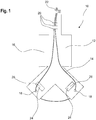
- FIG. 1 shows a holding device 10 according to the present invention in a front view.
- the holding device 10 comprises a flexible material 12 and a tensioning strap 14, in particular an elastic tensioning strap 14, which is connected to the flexible material 12.
- the flexible material 12 is for example a textile material, a tarpaulin, a fleece or the like.
- the flexible material 12 is provided with a coating, in particular a rubber coating 16, in order to increase a surface friction.
- the tensioning strap 14 For connecting the tensioning strap 14 to the flexible material 12, several openings are provided in the flexible material 12, in particular two holes 18 and several slits 20, in particular five slits 20.
- the holes 18 and the slits 20 are respectively arranged near to opposite ends of the holding device 10.
- the tensioning strap 14 is threaded through the two holes 18 and two of the several slits 20.
- the tensioning strap 14 can be threaded through different slits 20.
- the tensioning strap 14 may be threaded through the slits 20 located further inside in case of a small device, and in case of a larger device through correspondingly slits 20 located farther away from a center of the holding device 10.
- the fixing clip 22 may be a cord stop or the like.
- the positioning features 24 are provided in the flexible material 12.
- the positioning features 24 are elongated two cut-outs 26 in the flexible material 12, which are inclined with respect to a centerline of the holding device 10.
- the cut-outs 26 have a rectangular shape and are arranged perpendicular to each other.
- the corners of a mobile device should be inserted into the cut-outs 26 before tightening the tensioning strap 14. Thereby, the mobile device can be reliably held in the holding device 10.
- the flexible material 12 is substantially Y-shaped. Due to this shape, functional elements which are arranged in the area of the edges of a mobile device are accessible to a user. Furthermore, the display of a mobile device is accessible.
- the positioning features 24 and the holes 18 are arranged in the legs of the Y-shaped material, wherein the holes 18 are arranged on an outward facing side of the positioning features 24.
- FIG 2 shows the flexible material 12 of figure 1 in a back view.
- a Velcro material 30 is attached in the central area of the flexible material 12.
- the holding device 10 may be fastened to an corresponding Velcro element which may be arranged in a vehicle.
- the flexible material 12 comprises two lateral flaps 32 which are arranged in the central area of the flexible material 12, respectively the holding device 10. Thereby, the area to which a Velcro material 30 can be attached is enlarged.
- Figure 3 shows a mobile device 34, in particular a smartphone, that is attached to a holding device 10.
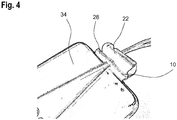
- the legs of the Y-shaped flexible material 12 of the holding device 10 are folded around two adjacent corners of the mobile device 34 and an abutment 28 is formed between an edge of the mobile device 34 and the fixing clip 22.
- the abutment 28 is a fold which is formed in the flexible material 12 by tightening the tensioning strap 14.
- an adhesive force between the flexible material 12 and the mobile device 34 is improved, such that the mobile device 34 is securely retained in the holding device 10.
- the abutment 28 inhibits that the fixing clip 22 might cause scratches on the mobile device 34.
- Figure 4 shows a detailed view of a section of the mobile device 34 in the holding device 10, in particular an enlarged view of the abutment 28.
Landscapes
- Engineering & Computer Science (AREA)
- Signal Processing (AREA)
- Theoretical Computer Science (AREA)
- Computer Networks & Wireless Communication (AREA)
- Computer Hardware Design (AREA)
- Human Computer Interaction (AREA)
- Physics & Mathematics (AREA)
- General Engineering & Computer Science (AREA)
- General Physics & Mathematics (AREA)
- Purses, Travelling Bags, Baskets, Or Suitcases (AREA)
- Telephone Set Structure (AREA)
Abstract
Description
- The invention refers to a holding device for a mobile device, in particular for a smartphone.
- Holding devices for mobile devices such as smartphones are well known. However, such holding devices are usually customized for a specific type of device, both in terms of design and holding function.
- Yet, for example in the case of rental vehicles, it is desired that different types of mobile devices can be reliably held in a single holding device.
- Holding devices are known which can at least to a slight extent adapt to devices with similar geometric dimensions. However, these holding devices reach their limits when it comes to devices with different external dimensions.
- Therefore, it is an object of the present invention to provide a holding device which is able to reliably hold various mobile devices which differ from each other in their outer dimensions.
- According to the invention, this problem is solved by providing a holding device for a mobile device comprising a flexible material, wherein at least one positioning feature is provided, and further comprising a tensioning strap being connected to the flexible material which is configured to pull the positioning feature towards an abutment in order reliably hold the mobile device within the holding device.
- Such a holding device has the advantage that it can be flexibly adapted to different geometries of different mobile devices. Furthermore, the holding device can be manufactured cost-effectively and has a low weight. Besides, the handling of the holding device is very easy.
- A mobile device can be mounted in the holding device by means of the at least one positioning feature. In particular, the at least one positioning feature is configured to prevent the mobile device from slipping out of the holding device, for example due to vibrations during driving.
- By means of the tensioning strap, the mobile device can be reliably fixed to the holding device. When tightening the tensioning strap, the flexible material can be bent and thereby encompass the mobile device at least at two opposite edges. Such, the mobile device is securely held in the holding device.
- The abutment can be a fold in the flexible material which is formed by tightening the tensioning strap.
- According to one embodiment, the positioning feature comprises two elongated cut-outs which are inclined relative to a centerline of the holding device and are oriented essentially perpendicularly to each other. The inclination of the cut-outs ensures that the corners of a mobile device are reliably held in the cut-outs and cannot slip out of them. A perpendicular arrangement of the cut-outs is particularly advantageous since most mobile devices are essentially rectangular in shape in a plan view.
- Additionally or alternatively, the positioning feature may include a pocket that is formed by folding the flexible material. In particular, the flexible material may be sewn up in order to form the pocket.
- Preferably, the flexible material is substantially Y-shaped, wherein the positioning features are arranged in the legs of the Y-shaped material. The Y-shape ensures that various functional elements of the mobile device are exposed and accessible to a user. Such functional elements may be different buttons, for example for volume control, sensors, camera lenses or a charging port, especially a USB port.
- Due to the flexibility of the material of the holding device, an angle between the legs of the Y can be variable at least to some extent. This means that the holding device can easily adapt to mobile devices with different widths.
- When tightening, the tensioning strap pulls the legs together laterally as well as in a direction towards a center of the holding device.
- According to a preferred embodiment, the flexible material is provided with a rubber coating. The rubber coating also inhibits that the mobile device slips out of the holding device. The rubber coating may be applied the complete surface of the flexible material, in particular a front side and a back side of the flexible material. Alternatively, the rubber coating may be applied only to a front side of the flexible material, wherein the front side is a side which is in contact with a mobile device when one is attached to the holding device. In a preferred embodiment, the flexible material is embedded in a rubber material.
- The holding device preferably comprises a fixing clip, wherein the tensioning strap is configured to be tightened by means of the fixing clip. Thereby, a tightening of the tensioning strap can be accomplished easily by pulling the tensioning strap. For example, the fixing clip is a cord stopper.
- According to one embodiment, the tensioning strap is elastic. Therefore, the mobile device can be held in the holding device under tension.
- Preferably, at least two slits, in particular parallel slits, are cut in the flexible material, wherein the ends of the tensioning strap are each threaded through both of the slits. Thereby, the tensioning strap is accessible on a front side of the holding device and can be easily tightened by a user.
- However, it is advantageous to provide several slits, for example three to ten slits, whereby the tensioning strap can be optionally threaded through two adjacent slits. Thereby, the holding device can be adapted to receive mobile devices with different dimensions, especially devices with different lengths.
- For example, the flexible material is a textile material, a tarpaulin or a fleece. Such materials do not trigger any touch events. In particular, no metal material and no plastic material with high graphite content should be present in a touch area of the mobile device. Furthermore, the flexible material should not be elastic or only slightly elastic.
- According to one embodiment, a Velcro material is attached to the back of the flexible material at least in a central area of the holding device. The Velcro material can be used to fasten the holding device in the interior of the vehicle, for example by attaching a corresponding counterpart of a Velcro fastener in the vehicle. Thereby, the holding device can easily be attached or detached in the vehicle interior. However, other fastening options are also possible, e. g. by means of tension straps, latching elements, adhesive tape etc.
- The Velcro material may be sewn or glued to the flexible material.
- The flexible material may comprise at least one flap which is arranged in the central area of the holding device. By means of the flap, the area which is available for applying a Velcro material is enlarged. Thereby, a sufficient holding force can be achieved.
- Further advantages and features of the invention result from the following description and from the drawings to which reference is made. The drawings show:
-
Figure 1 a holding device according to the present invention in a front view, -
Figure 2 the flexible material of a holding device according to the present invention in a back view, -
Figure 3 a holding device according to the present invention with a mobile device attached to the holding device and -
Figure 4 a detailed view of a part of a mobile device attached in the holding device. -
Figure 1 shows aholding device 10 according to the present invention in a front view. Theholding device 10 comprises aflexible material 12 and atensioning strap 14, in particular anelastic tensioning strap 14, which is connected to theflexible material 12. - The
flexible material 12 is for example a textile material, a tarpaulin, a fleece or the like. - At least on the front side of the
holding device 10, theflexible material 12 is provided with a coating, in particular arubber coating 16, in order to increase a surface friction. - For connecting the
tensioning strap 14 to theflexible material 12, several openings are provided in theflexible material 12, in particular twoholes 18 andseveral slits 20, in particular fiveslits 20. Theholes 18 and theslits 20 are respectively arranged near to opposite ends of the holdingdevice 10. The tensioningstrap 14 is threaded through the twoholes 18 and two of the several slits 20. - Depending on the size of a mobile device to be attached, especially the length, the tensioning
strap 14 can be threaded throughdifferent slits 20. In particular, the tensioningstrap 14 may be threaded through theslits 20 located further inside in case of a small device, and in case of a larger device through correspondingly slits 20 located farther away from a center of the holdingdevice 10. - In order to tighten the
tensioning strap 14, a fixingclip 22 is provided. The fixingclip 22 may be a cord stop or the like. - When the
tensioning strap 14 is tightened in order to attach a mobile device to the holdingdevice 10, the flexible material between the twoslits 20 through which thetensioning strap 14 gets folded, thereby forming anabutment 28 against which the mobile device is pressed. Such anabutment 28 can be seen infigures 3 and4 . - For the purpose of reliably holding a mobile device in the holding
device 10, two positioning features 24 are provided in theflexible material 12. In the illustrated embodiment, the positioning features 24 are elongated two cut-outs 26 in theflexible material 12, which are inclined with respect to a centerline of the holdingdevice 10. In particular, the cut-outs 26 have a rectangular shape and are arranged perpendicular to each other. - When attaching a mobile device to the holding
device 10, the corners of a mobile device should be inserted into the cut-outs 26 before tightening thetensioning strap 14. Thereby, the mobile device can be reliably held in the holdingdevice 10. - The
flexible material 12 is substantially Y-shaped. Due to this shape, functional elements which are arranged in the area of the edges of a mobile device are accessible to a user. Furthermore, the display of a mobile device is accessible. - The positioning features 24 and the
holes 18 are arranged in the legs of the Y-shaped material, wherein theholes 18 are arranged on an outward facing side of the positioning features 24. -
Figure 2 shows theflexible material 12 offigure 1 in a back view. In the central area of theflexible material 12, aVelcro material 30 is attached. Thereby, the holdingdevice 10 may be fastened to an corresponding Velcro element which may be arranged in a vehicle. - The
flexible material 12 comprises twolateral flaps 32 which are arranged in the central area of theflexible material 12, respectively the holdingdevice 10. Thereby, the area to which aVelcro material 30 can be attached is enlarged. -
Figure 3 shows amobile device 34, in particular a smartphone, that is attached to a holdingdevice 10. The legs of the Y-shapedflexible material 12 of the holdingdevice 10 are folded around two adjacent corners of themobile device 34 and anabutment 28 is formed between an edge of themobile device 34 and the fixingclip 22. In particular, theabutment 28 is a fold which is formed in theflexible material 12 by tightening thetensioning strap 14. By means of theabutment 28 an adhesive force between theflexible material 12 and themobile device 34 is improved, such that themobile device 34 is securely retained in the holdingdevice 10. Furthermore, theabutment 28 inhibits that the fixingclip 22 might cause scratches on themobile device 34. -
Figure 4 shows a detailed view of a section of themobile device 34 in the holdingdevice 10, in particular an enlarged view of theabutment 28.
Claims (10)
- Holding device (10) for a mobile device (34), comprising a flexible material (12), wherein at least one positioning feature (24) is provided, and further comprising a tensioning strap (14) being connected to the flexible material (12) which is configured to pull the positioning feature (24) towards an abutment (28) in order reliably hold the mobile device (34) within the holding device (10).
- Holding device (10) according to claim 1, wherein the positioning feature (24) comprises two elongated cut-outs (26) which are inclined relative to a centerline of the holding device (10) and essentially perpendicular to each other.
- Holding device (10) according to any of the preceding claims, wherein the flexible material (12) is substantially Y-shaped, and wherein the positioning feature (24) is arranged in the legs of the Y-shaped material.
- Holding device (10) according to any of the preceding claims, wherein the flexible material (12) is provided with a rubber coating (16).
- Holding device (10) according to any of the preceding claims, wherein the holding device (10) comprises a fixing clip (22), wherein the tensioning strap (14) is configured to be tightened by means of the fixing clip (22).
- Holding device (10) according to any of the preceding claims, wherein the tensioning strap (14) is elastic.
- Holding device (10) according to any of the preceding claims, wherein at least two slits (20) are cut in the flexible material (12), wherein the ends of the tensioning strap (14) are each threaded through both of the slits (20).
- Holding device (10) according to any of the preceding claims, wherein the flexible material (12) is a textile material, a tarpaulin or a fleece.
- Holding device (10) according to any of the preceding claims, wherein a Velcro material (30) is attached to the back of the flexible material (12) at least in a central area of the holding device (10).
- Holding device (10) according any of the preceding claims, wherein the flexible material (12) comprises at least one flap (32) which is arranged in the central area of the holding device (10).
Priority Applications (1)
| Application Number | Priority Date | Filing Date | Title |
|---|---|---|---|
| EP18154721.7A EP3522507B1 (en) | 2018-02-01 | 2018-02-01 | Holding device for a mobile device |
Applications Claiming Priority (1)
| Application Number | Priority Date | Filing Date | Title |
|---|---|---|---|
| EP18154721.7A EP3522507B1 (en) | 2018-02-01 | 2018-02-01 | Holding device for a mobile device |
Publications (2)
| Publication Number | Publication Date |
|---|---|
| EP3522507A1 true EP3522507A1 (en) | 2019-08-07 |
| EP3522507B1 EP3522507B1 (en) | 2021-04-28 |
Family
ID=61132321
Family Applications (1)
| Application Number | Title | Priority Date | Filing Date |
|---|---|---|---|
| EP18154721.7A Active EP3522507B1 (en) | 2018-02-01 | 2018-02-01 | Holding device for a mobile device |
Country Status (1)
| Country | Link |
|---|---|
| EP (1) | EP3522507B1 (en) |
Cited By (1)
| Publication number | Priority date | Publication date | Assignee | Title |
|---|---|---|---|---|
| SE548262C2 (en) * | 2024-11-15 | 2026-05-05 | Skagmech Ab | Mobile device holder |
Citations (5)
| Publication number | Priority date | Publication date | Assignee | Title |
|---|---|---|---|---|
| US20050221762A1 (en) * | 2004-04-06 | 2005-10-06 | Marcelle Greene | Cellular phone holster |
| US20060186150A1 (en) * | 2005-02-24 | 2006-08-24 | Willows Keith S | Item carrier |
| US20130081969A1 (en) * | 2011-09-29 | 2013-04-04 | Joshua T. Morenstein | Apparatus for securing an electronic device in a cover |
| US20140259538A1 (en) * | 2013-03-15 | 2014-09-18 | Daca Design Llc | Securement apparatus for a portable electronic device |
| US20150288406A1 (en) * | 2014-04-08 | 2015-10-08 | American Covers, Inc. | Strechable strap cover for electronic device |
Family Cites Families (1)
| Publication number | Priority date | Publication date | Assignee | Title |
|---|---|---|---|---|
| US4248366A (en) * | 1979-05-10 | 1981-02-03 | Christiansen James S | Adjustable beverage container holder |
-
2018
- 2018-02-01 EP EP18154721.7A patent/EP3522507B1/en active Active
Patent Citations (5)
| Publication number | Priority date | Publication date | Assignee | Title |
|---|---|---|---|---|
| US20050221762A1 (en) * | 2004-04-06 | 2005-10-06 | Marcelle Greene | Cellular phone holster |
| US20060186150A1 (en) * | 2005-02-24 | 2006-08-24 | Willows Keith S | Item carrier |
| US20130081969A1 (en) * | 2011-09-29 | 2013-04-04 | Joshua T. Morenstein | Apparatus for securing an electronic device in a cover |
| US20140259538A1 (en) * | 2013-03-15 | 2014-09-18 | Daca Design Llc | Securement apparatus for a portable electronic device |
| US20150288406A1 (en) * | 2014-04-08 | 2015-10-08 | American Covers, Inc. | Strechable strap cover for electronic device |
Cited By (2)
| Publication number | Priority date | Publication date | Assignee | Title |
|---|---|---|---|---|
| SE548262C2 (en) * | 2024-11-15 | 2026-05-05 | Skagmech Ab | Mobile device holder |
| SE2430579A1 (en) * | 2024-11-15 | 2026-05-05 | Skagmech Ab | Mobile device holder |
Also Published As
| Publication number | Publication date |
|---|---|
| EP3522507B1 (en) | 2021-04-28 |
Similar Documents
| Publication | Publication Date | Title |
|---|---|---|
| US11523666B2 (en) | Securement apparatus for a portable electronic device | |
| US8561862B2 (en) | Personal securing apparatus for handheld devices | |
| US9259077B2 (en) | Elastic securing apparatus and mounting system for electronic device | |
| US20190350351A1 (en) | Securing apparatus for a case for an electronic device | |
| US20140217135A1 (en) | Flexible finger strap and surface mount for electronic device | |
| US11877635B2 (en) | Carry straps for electronic display devices | |
| US3144274A (en) | Magnetic anchor for seat belt buckles | |
| US20120080469A1 (en) | Apparatus for carrying hand-held wireless electronic device | |
| US20070011850A1 (en) | Strap securing device | |
| US11133122B2 (en) | Magnetic anchoring devices | |
| US10807453B2 (en) | Hand-held magnetic clamping device for car covers | |
| EP3522507B1 (en) | Holding device for a mobile device | |
| KR20140109301A (en) | Adjustable securing device and buckle | |
| US11358549B2 (en) | Removable grill cover and attachment clip | |
| US20130228603A1 (en) | Carrier for a wireless receiver or transmitter | |
| US8002095B2 (en) | Buckle and elastic luggage strap | |
| JP2013023097A (en) | Carrier in vehicle | |
| JP2018054128A (en) | Lashing hook and packing string | |
| US8465824B2 (en) | Strap for securing accessories to photographic flash units | |
| US20220089093A1 (en) | Mask caddy | |
| JP3193394U (en) | Car carrier | |
| CN211969333U (en) | Driver tool fixing device and vehicle | |
| CN205163980U (en) | Fire extinguisher bracket | |
| US9041929B2 (en) | Method for securing a display diagnostic device to a display | |
| US20040087210A1 (en) | Tethered electrical component for vehicles |
Legal Events
| Date | Code | Title | Description |
|---|---|---|---|
| PUAI | Public reference made under article 153(3) epc to a published international application that has entered the european phase |
Free format text: ORIGINAL CODE: 0009012 |
|
| STAA | Information on the status of an ep patent application or granted ep patent |
Free format text: STATUS: THE APPLICATION HAS BEEN PUBLISHED |
|
| AK | Designated contracting states |
Kind code of ref document: A1 Designated state(s): AL AT BE BG CH CY CZ DE DK EE ES FI FR GB GR HR HU IE IS IT LI LT LU LV MC MK MT NL NO PL PT RO RS SE SI SK SM TR |
|
| AX | Request for extension of the european patent |
Extension state: BA ME |
|
| STAA | Information on the status of an ep patent application or granted ep patent |
Free format text: STATUS: REQUEST FOR EXAMINATION WAS MADE |
|
| 17P | Request for examination filed |
Effective date: 20200131 |
|
| RBV | Designated contracting states (corrected) |
Designated state(s): AL AT BE BG CH CY CZ DE DK EE ES FI FR GB GR HR HU IE IS IT LI LT LU LV MC MK MT NL NO PL PT RO RS SE SI SK SM TR |
|
| STAA | Information on the status of an ep patent application or granted ep patent |
Free format text: STATUS: EXAMINATION IS IN PROGRESS |
|
| 17Q | First examination report despatched |
Effective date: 20200707 |
|
| GRAP | Despatch of communication of intention to grant a patent |
Free format text: ORIGINAL CODE: EPIDOSNIGR1 |
|
| STAA | Information on the status of an ep patent application or granted ep patent |
Free format text: STATUS: GRANT OF PATENT IS INTENDED |
|
| RIC1 | Information provided on ipc code assigned before grant |
Ipc: H04B 1/3888 20150101ALI20201120BHEP Ipc: A45F 5/00 20060101ALI20201120BHEP Ipc: B60R 11/02 20060101ALI20201120BHEP Ipc: H04M 1/04 20060101AFI20201120BHEP Ipc: H04B 1/3877 20150101ALI20201120BHEP Ipc: G06F 1/16 20060101ALI20201120BHEP |
|
| INTG | Intention to grant announced |
Effective date: 20201211 |
|
| GRAS | Grant fee paid |
Free format text: ORIGINAL CODE: EPIDOSNIGR3 |
|
| GRAA | (expected) grant |
Free format text: ORIGINAL CODE: 0009210 |
|
| STAA | Information on the status of an ep patent application or granted ep patent |
Free format text: STATUS: THE PATENT HAS BEEN GRANTED |
|
| AK | Designated contracting states |
Kind code of ref document: B1 Designated state(s): AL AT BE BG CY CZ DE DK EE ES FI FR GB GR HR HU IS IT LT LU LV MC MK MT NL NO PL PT RO RS SE SI SK SM TR |
|
| RBV | Designated contracting states (corrected) |
Designated state(s): AL AT BE BG CY CZ DE DK EE ES FI FR GB GR HR HU IS IT LT LU LV MC MK MT NL NO PL PT RO RS SE SI SK SM TR |
|
| REG | Reference to a national code |
Ref country code: GB Ref legal event code: FG4D |
|
| REG | Reference to a national code |
Ref country code: AT Ref legal event code: REF Ref document number: 1388441 Country of ref document: AT Kind code of ref document: T Effective date: 20210515 |
|
| REG | Reference to a national code |
Ref country code: DE Ref legal event code: R096 Ref document number: 602018016035 Country of ref document: DE |
|
| REG | Reference to a national code |
Ref country code: LT Ref legal event code: MG9D |
|
| REG | Reference to a national code |
Ref country code: AT Ref legal event code: MK05 Ref document number: 1388441 Country of ref document: AT Kind code of ref document: T Effective date: 20210428 |
|
| PG25 | Lapsed in a contracting state [announced via postgrant information from national office to epo] |
Ref country code: NL Free format text: LAPSE BECAUSE OF FAILURE TO SUBMIT A TRANSLATION OF THE DESCRIPTION OR TO PAY THE FEE WITHIN THE PRESCRIBED TIME-LIMIT Effective date: 20210428 Ref country code: HR Free format text: LAPSE BECAUSE OF FAILURE TO SUBMIT A TRANSLATION OF THE DESCRIPTION OR TO PAY THE FEE WITHIN THE PRESCRIBED TIME-LIMIT Effective date: 20210428 Ref country code: AT Free format text: LAPSE BECAUSE OF FAILURE TO SUBMIT A TRANSLATION OF THE DESCRIPTION OR TO PAY THE FEE WITHIN THE PRESCRIBED TIME-LIMIT Effective date: 20210428 Ref country code: BG Free format text: LAPSE BECAUSE OF FAILURE TO SUBMIT A TRANSLATION OF THE DESCRIPTION OR TO PAY THE FEE WITHIN THE PRESCRIBED TIME-LIMIT Effective date: 20210728 Ref country code: FI Free format text: LAPSE BECAUSE OF FAILURE TO SUBMIT A TRANSLATION OF THE DESCRIPTION OR TO PAY THE FEE WITHIN THE PRESCRIBED TIME-LIMIT Effective date: 20210428 Ref country code: LT Free format text: LAPSE BECAUSE OF FAILURE TO SUBMIT A TRANSLATION OF THE DESCRIPTION OR TO PAY THE FEE WITHIN THE PRESCRIBED TIME-LIMIT Effective date: 20210428 |
|
| PG25 | Lapsed in a contracting state [announced via postgrant information from national office to epo] |
Ref country code: GR Free format text: LAPSE BECAUSE OF FAILURE TO SUBMIT A TRANSLATION OF THE DESCRIPTION OR TO PAY THE FEE WITHIN THE PRESCRIBED TIME-LIMIT Effective date: 20210729 Ref country code: IS Free format text: LAPSE BECAUSE OF FAILURE TO SUBMIT A TRANSLATION OF THE DESCRIPTION OR TO PAY THE FEE WITHIN THE PRESCRIBED TIME-LIMIT Effective date: 20210828 Ref country code: NO Free format text: LAPSE BECAUSE OF FAILURE TO SUBMIT A TRANSLATION OF THE DESCRIPTION OR TO PAY THE FEE WITHIN THE PRESCRIBED TIME-LIMIT Effective date: 20210728 Ref country code: PL Free format text: LAPSE BECAUSE OF FAILURE TO SUBMIT A TRANSLATION OF THE DESCRIPTION OR TO PAY THE FEE WITHIN THE PRESCRIBED TIME-LIMIT Effective date: 20210428 Ref country code: LV Free format text: LAPSE BECAUSE OF FAILURE TO SUBMIT A TRANSLATION OF THE DESCRIPTION OR TO PAY THE FEE WITHIN THE PRESCRIBED TIME-LIMIT Effective date: 20210428 Ref country code: PT Free format text: LAPSE BECAUSE OF FAILURE TO SUBMIT A TRANSLATION OF THE DESCRIPTION OR TO PAY THE FEE WITHIN THE PRESCRIBED TIME-LIMIT Effective date: 20210830 Ref country code: SE Free format text: LAPSE BECAUSE OF FAILURE TO SUBMIT A TRANSLATION OF THE DESCRIPTION OR TO PAY THE FEE WITHIN THE PRESCRIBED TIME-LIMIT Effective date: 20210428 Ref country code: RS Free format text: LAPSE BECAUSE OF FAILURE TO SUBMIT A TRANSLATION OF THE DESCRIPTION OR TO PAY THE FEE WITHIN THE PRESCRIBED TIME-LIMIT Effective date: 20210428 |
|
| REG | Reference to a national code |
Ref country code: NL Ref legal event code: MP Effective date: 20210428 |
|
| PG25 | Lapsed in a contracting state [announced via postgrant information from national office to epo] |
Ref country code: ES Free format text: LAPSE BECAUSE OF FAILURE TO SUBMIT A TRANSLATION OF THE DESCRIPTION OR TO PAY THE FEE WITHIN THE PRESCRIBED TIME-LIMIT Effective date: 20210428 Ref country code: EE Free format text: LAPSE BECAUSE OF FAILURE TO SUBMIT A TRANSLATION OF THE DESCRIPTION OR TO PAY THE FEE WITHIN THE PRESCRIBED TIME-LIMIT Effective date: 20210428 Ref country code: SK Free format text: LAPSE BECAUSE OF FAILURE TO SUBMIT A TRANSLATION OF THE DESCRIPTION OR TO PAY THE FEE WITHIN THE PRESCRIBED TIME-LIMIT Effective date: 20210428 Ref country code: SM Free format text: LAPSE BECAUSE OF FAILURE TO SUBMIT A TRANSLATION OF THE DESCRIPTION OR TO PAY THE FEE WITHIN THE PRESCRIBED TIME-LIMIT Effective date: 20210428 Ref country code: RO Free format text: LAPSE BECAUSE OF FAILURE TO SUBMIT A TRANSLATION OF THE DESCRIPTION OR TO PAY THE FEE WITHIN THE PRESCRIBED TIME-LIMIT Effective date: 20210428 Ref country code: CZ Free format text: LAPSE BECAUSE OF FAILURE TO SUBMIT A TRANSLATION OF THE DESCRIPTION OR TO PAY THE FEE WITHIN THE PRESCRIBED TIME-LIMIT Effective date: 20210428 Ref country code: DK Free format text: LAPSE BECAUSE OF FAILURE TO SUBMIT A TRANSLATION OF THE DESCRIPTION OR TO PAY THE FEE WITHIN THE PRESCRIBED TIME-LIMIT Effective date: 20210428 |
|
| REG | Reference to a national code |
Ref country code: DE Ref legal event code: R097 Ref document number: 602018016035 Country of ref document: DE |
|
| PLBE | No opposition filed within time limit |
Free format text: ORIGINAL CODE: 0009261 |
|
| STAA | Information on the status of an ep patent application or granted ep patent |
Free format text: STATUS: NO OPPOSITION FILED WITHIN TIME LIMIT |
|
| 26N | No opposition filed |
Effective date: 20220131 |
|
| PG25 | Lapsed in a contracting state [announced via postgrant information from national office to epo] |
Ref country code: IS Free format text: LAPSE BECAUSE OF FAILURE TO SUBMIT A TRANSLATION OF THE DESCRIPTION OR TO PAY THE FEE WITHIN THE PRESCRIBED TIME-LIMIT Effective date: 20210828 Ref country code: AL Free format text: LAPSE BECAUSE OF FAILURE TO SUBMIT A TRANSLATION OF THE DESCRIPTION OR TO PAY THE FEE WITHIN THE PRESCRIBED TIME-LIMIT Effective date: 20210428 |
|
| PG25 | Lapsed in a contracting state [announced via postgrant information from national office to epo] |
Ref country code: IT Free format text: LAPSE BECAUSE OF FAILURE TO SUBMIT A TRANSLATION OF THE DESCRIPTION OR TO PAY THE FEE WITHIN THE PRESCRIBED TIME-LIMIT Effective date: 20210428 |
|
| PG25 | Lapsed in a contracting state [announced via postgrant information from national office to epo] |
Ref country code: MC Free format text: LAPSE BECAUSE OF FAILURE TO SUBMIT A TRANSLATION OF THE DESCRIPTION OR TO PAY THE FEE WITHIN THE PRESCRIBED TIME-LIMIT Effective date: 20210428 |
|
| REG | Reference to a national code |
Ref country code: BE Ref legal event code: MM Effective date: 20220228 |
|
| PG25 | Lapsed in a contracting state [announced via postgrant information from national office to epo] |
Ref country code: LU Free format text: LAPSE BECAUSE OF NON-PAYMENT OF DUE FEES Effective date: 20220201 |
|
| PG25 | Lapsed in a contracting state [announced via postgrant information from national office to epo] |
Ref country code: BE Free format text: LAPSE BECAUSE OF NON-PAYMENT OF DUE FEES Effective date: 20220228 |
|
| P01 | Opt-out of the competence of the unified patent court (upc) registered |
Effective date: 20230525 |
|
| PG25 | Lapsed in a contracting state [announced via postgrant information from national office to epo] |
Ref country code: MK Free format text: LAPSE BECAUSE OF FAILURE TO SUBMIT A TRANSLATION OF THE DESCRIPTION OR TO PAY THE FEE WITHIN THE PRESCRIBED TIME-LIMIT Effective date: 20210428 Ref country code: CY Free format text: LAPSE BECAUSE OF FAILURE TO SUBMIT A TRANSLATION OF THE DESCRIPTION OR TO PAY THE FEE WITHIN THE PRESCRIBED TIME-LIMIT Effective date: 20210428 |
|
| PG25 | Lapsed in a contracting state [announced via postgrant information from national office to epo] |
Ref country code: HU Free format text: LAPSE BECAUSE OF FAILURE TO SUBMIT A TRANSLATION OF THE DESCRIPTION OR TO PAY THE FEE WITHIN THE PRESCRIBED TIME-LIMIT; INVALID AB INITIO Effective date: 20180201 |
|
| PG25 | Lapsed in a contracting state [announced via postgrant information from national office to epo] |
Ref country code: MT Free format text: LAPSE BECAUSE OF FAILURE TO SUBMIT A TRANSLATION OF THE DESCRIPTION OR TO PAY THE FEE WITHIN THE PRESCRIBED TIME-LIMIT Effective date: 20210428 |
|
| PG25 | Lapsed in a contracting state [announced via postgrant information from national office to epo] |
Ref country code: TR Free format text: LAPSE BECAUSE OF FAILURE TO SUBMIT A TRANSLATION OF THE DESCRIPTION OR TO PAY THE FEE WITHIN THE PRESCRIBED TIME-LIMIT Effective date: 20210428 |
|
| PGFP | Annual fee paid to national office [announced via postgrant information from national office to epo] |
Ref country code: GB Payment date: 20260219 Year of fee payment: 9 |
|
| PGFP | Annual fee paid to national office [announced via postgrant information from national office to epo] |
Ref country code: DE Payment date: 20260217 Year of fee payment: 9 |
|
| PGFP | Annual fee paid to national office [announced via postgrant information from national office to epo] |
Ref country code: FR Payment date: 20260223 Year of fee payment: 9 |