EP3522457A1 - Dedicated virtual local area network for peer-to-peer traffic transmitted between switches - Google Patents
Dedicated virtual local area network for peer-to-peer traffic transmitted between switches Download PDFInfo
- Publication number
- EP3522457A1 EP3522457A1 EP19152849.6A EP19152849A EP3522457A1 EP 3522457 A1 EP3522457 A1 EP 3522457A1 EP 19152849 A EP19152849 A EP 19152849A EP 3522457 A1 EP3522457 A1 EP 3522457A1
- Authority
- EP
- European Patent Office
- Prior art keywords
- switch
- peer
- vlan
- traffic
- source
- Prior art date
- Legal status (The legal status is an assumption and is not a legal conclusion. Google has not performed a legal analysis and makes no representation as to the accuracy of the status listed.)
- Granted
Links
- 238000000034 method Methods 0.000 claims abstract description 12
- 238000003860 storage Methods 0.000 claims description 25
- 230000004044 response Effects 0.000 claims description 5
- 238000011144 upstream manufacturing Methods 0.000 claims description 5
- 238000010586 diagram Methods 0.000 description 6
- 238000004891 communication Methods 0.000 description 5
- 238000007726 management method Methods 0.000 description 5
- 230000008569 process Effects 0.000 description 5
- 101000610620 Homo sapiens Putative serine protease 29 Proteins 0.000 description 3
- 101150045440 ISP1 gene Proteins 0.000 description 3
- 101100353471 Mus musculus Prss28 gene Proteins 0.000 description 3
- 102100040345 Putative serine protease 29 Human genes 0.000 description 3
- 101100509103 Schizosaccharomyces pombe (strain 972 / ATCC 24843) ish1 gene Proteins 0.000 description 3
- 230000008520 organization Effects 0.000 description 3
- 238000005516 engineering process Methods 0.000 description 2
- 238000004519 manufacturing process Methods 0.000 description 2
- 230000006855 networking Effects 0.000 description 2
- 230000011664 signaling Effects 0.000 description 2
- 230000005540 biological transmission Effects 0.000 description 1
- 230000001413 cellular effect Effects 0.000 description 1
- 238000009826 distribution Methods 0.000 description 1
- 230000006870 function Effects 0.000 description 1
- 230000007246 mechanism Effects 0.000 description 1
- 230000003287 optical effect Effects 0.000 description 1
- 238000012913 prioritisation Methods 0.000 description 1
- 239000004065 semiconductor Substances 0.000 description 1
- 239000007787 solid Substances 0.000 description 1
Images


Classifications
-
- H—ELECTRICITY
- H04—ELECTRIC COMMUNICATION TECHNIQUE
- H04L—TRANSMISSION OF DIGITAL INFORMATION, e.g. TELEGRAPHIC COMMUNICATION
- H04L49/00—Packet switching elements
- H04L49/25—Routing or path finding in a switch fabric
-
- H—ELECTRICITY
- H04—ELECTRIC COMMUNICATION TECHNIQUE
- H04L—TRANSMISSION OF DIGITAL INFORMATION, e.g. TELEGRAPHIC COMMUNICATION
- H04L12/00—Data switching networks
- H04L12/28—Data switching networks characterised by path configuration, e.g. LAN [Local Area Networks] or WAN [Wide Area Networks]
- H04L12/46—Interconnection of networks
- H04L12/4641—Virtual LANs, VLANs, e.g. virtual private networks [VPN]
-
- H—ELECTRICITY
- H04—ELECTRIC COMMUNICATION TECHNIQUE
- H04L—TRANSMISSION OF DIGITAL INFORMATION, e.g. TELEGRAPHIC COMMUNICATION
- H04L45/00—Routing or path finding of packets in data switching networks
- H04L45/74—Address processing for routing
-
- H—ELECTRICITY
- H04—ELECTRIC COMMUNICATION TECHNIQUE
- H04L—TRANSMISSION OF DIGITAL INFORMATION, e.g. TELEGRAPHIC COMMUNICATION
- H04L45/00—Routing or path finding of packets in data switching networks
- H04L45/74—Address processing for routing
- H04L45/745—Address table lookup; Address filtering
-
- H—ELECTRICITY
- H04—ELECTRIC COMMUNICATION TECHNIQUE
- H04L—TRANSMISSION OF DIGITAL INFORMATION, e.g. TELEGRAPHIC COMMUNICATION
- H04L47/00—Traffic control in data switching networks
- H04L47/10—Flow control; Congestion control
- H04L47/20—Traffic policing
-
- H—ELECTRICITY
- H04—ELECTRIC COMMUNICATION TECHNIQUE
- H04L—TRANSMISSION OF DIGITAL INFORMATION, e.g. TELEGRAPHIC COMMUNICATION
- H04L47/00—Traffic control in data switching networks
- H04L47/10—Flow control; Congestion control
- H04L47/24—Traffic characterised by specific attributes, e.g. priority or QoS
- H04L47/245—Traffic characterised by specific attributes, e.g. priority or QoS using preemption
-
- H—ELECTRICITY
- H04—ELECTRIC COMMUNICATION TECHNIQUE
- H04L—TRANSMISSION OF DIGITAL INFORMATION, e.g. TELEGRAPHIC COMMUNICATION
- H04L61/00—Network arrangements, protocols or services for addressing or naming
- H04L61/45—Network directories; Name-to-address mapping
- H04L61/4552—Lookup mechanisms between a plurality of directories; Synchronisation of directories, e.g. metadirectories
-
- H—ELECTRICITY
- H04—ELECTRIC COMMUNICATION TECHNIQUE
- H04L—TRANSMISSION OF DIGITAL INFORMATION, e.g. TELEGRAPHIC COMMUNICATION
- H04L61/00—Network arrangements, protocols or services for addressing or naming
- H04L61/50—Address allocation
- H04L61/5007—Internet protocol [IP] addresses
- H04L61/5014—Internet protocol [IP] addresses using dynamic host configuration protocol [DHCP] or bootstrap protocol [BOOTP]
-
- H—ELECTRICITY
- H04—ELECTRIC COMMUNICATION TECHNIQUE
- H04L—TRANSMISSION OF DIGITAL INFORMATION, e.g. TELEGRAPHIC COMMUNICATION
- H04L67/00—Network arrangements or protocols for supporting network services or applications
- H04L67/01—Protocols
- H04L67/10—Protocols in which an application is distributed across nodes in the network
- H04L67/104—Peer-to-peer [P2P] networks
Definitions
- SD-WAN wide area network
- WAN wide area network
- MPLS multiprotocol label switching
- Gateway controllers can be deployed at the branch offices in a SD-WAN solution. Redundancy of gateway peers are usually provided so that the gateway branch controllers can be highly available. Also, traffic can be load balanced across the redundant gateway peers.
- An example SD-WAN branch deployment may include a plurality of branch gateway controller peers that are highly available to provide redundancies for the gateway peers.
- the branch gateway peers can provide uplink connectivity, traffic load balancing, policy-based routing, etc.
- traffic load are balanced among at least two branch gateway peers.
- these two branch gateway peers may be connected through a network switch.
- they can operate in an active-active model to service branch wireless and wired clients. For example, in an active-active model, about half of the client devices in the network may terminate on a first branch gateway peer, and the other half of the network client devices in the network may terminate on a second branch gateway peer.
- Each gateway peer may be connected with an access point.
- a direct peer-to-peer link may be used for one-to-one communications across the branch gateway controller peers.
- Peer-to-peer traffic can be enforced to pass through the direct link between the branch gateway controller peers in order to achieve better throughput, efficiency, and prioritization.
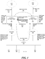
- FIG. 1 is a block diagram of an example system deployment for dedicated virtual local area network for peer-to-peer traffic transmitted between switches.
- FIG 1 includes two branch gateway peers, such as, branch gateway peer 1 130 and branch gateway peer 2 135. Although two branch gateway peers are illustrated here, an example branch deployment may have more than two branch gateway peers.
- Each branch gateway peer (130 or 135) has an uplink connection that may connect to an Internet Service Provider (ISP).
- ISP Internet Service Provider
- branch gateway peer 1 130 is connected to ISP1 110
- branch gateway peer 2 135 is connected to ISP2 115.
- An ISP generally refers to an entity that provides enterprises or individual users with access to the Internet and other related services. The ISP has the equipment and the telecommunication line access required to have a point-of-presence on the Internet for the geographic area served.
- branch gateway peers 130 and 135 can manage a plurality of client devices through a plurality of access points (e.g., AP1 180, AP2 182, ... APn 188) deployed in the example branch network.
- the plurality of APs 180-188 may be connected to ports of at least one Layer-2 switch in the network switch via wired connections.
- network device generally includes a device that is adapted to transmit and/or receive signaling and to process information within such signaling such as a station (e.g., any data processing equipment such as a computer, cellular phone, personal digital assistant, tablet devices, etc.), an access point, data transfer devices (such as network switches, routers, controllers, etc.) or the like.
- a “network device may refer to a network controller that comprises a hardware or a combination of hardware and software that enables connection between client devices and computer networks.
- a network device may refer to a server computing device (e.g., on-premise server, private, public, or hybrid cloud server) that comprises a hardware or a combination of hardware and software that can process and/or display network-related information.
- a network device may refer to an access point acting as a virtual master network controller among a cluster of access points.
- 'access point' generally refers to receiving points for any known or convenient wireless access technology which may later become known.
- AP is not intended to be limited to IEEE 802.11-based APs.
- APs generally function as an electronic device that is adapted to allow wireless devices to connect to a wired network via various communications standards.
- Branch gateway peer 1 130 and branch gateway peer 135 provides redundancy for each other.
- one half of the clients in the network are managed by branch gateway peer 1 130, while the other half of the clients in the network are managed by branch gateway peer2 135.
- branch gateway peer 2 135, as the backup peer would manage the half of the clients previously managed by branch gateway peer 1 130, and vice versa.
- VLAN virtual local area network
- ISP2 115 and branch gateway peer 2 135 are transmitted on uplink VLAN 125 associated with ISP2 115.
- a VLAN may generally refer to a logical group of workstations, servers and network devices that appear to be on the same LAN despite their geographical distribution.
- a VLAN can allow a network of computers and users to communicate in a simulated environment as if they exist in a single LAN and are sharing a single broadcast and multicast domain.
- configuration 152 shows an example configuration for uplink VLAN 120.
- VLAN 1 120 has an address space of 1.1.1.1/24.
- VLAN 1 120 may be a VLAN dedicated to transmit traffic to and from devices associated with employees of an organization.
- configuration 158 shows an example configuration for uplink VLAN 125.
- VLAN 5 125 has an address space of 5.5.5.2/24.
- VLAN 5 125 may be a VLAN dedicated to transmit traffic to and from devices associated with guests of the organization.
- routing path 165 can be used to transmit traffic between branch gateway peers 130 and 135 via router 1 150, at least one Layer-2 switch 170, and router 2 160.
- router 1 150 is connected to a trunk port 142 of branch gateway peer 1 130 where user VLANs are allowed.
- router 2 160 is connected to a trunk port 144 of branch gateway peer 2 135 where user VLANs are allowed. Trunk ports 142 and 144 generally refer to ports of a switch that are configured to carry traffic that belongs to multiple VLANs over the same link.
- user VLANs may generally refer to VLANs that are dedicated for traffic to and from a group of client devices in the network. This is in contrast to “management VLANs,” which may be used to transmit management and/or control frames among network management devices in a network, e.g., between wireless controllers and access points, etc.
- router 1 150 is configured with VLAN address 3.3.3.1/24
- router 2 160 is configured with VLAN address 4 .4 .4 .1/24.
- the system may be configured with policy-based routing schemes. For instance, a policy may state that traffic to or from client devices associated with employees of the organization is transmitted through branch gateway peer 1 130. However, if a client device associated with an employee has been authenticated into the network, then traffic to and from the authenticated client device may be transmitted through branch gateway peer 2 135.
- the system may inspect the traffic to determine whether the traffic belongs to a high priority. If the system determines that the traffic belongs to the high priority, the traffic is transmitted through branch gateway peer 1 130. However, if the system determines that the traffic does not belong to a high priority, then the traffic is transmitted through branch gateway peer 2 135.
- peer-to-peer traffic can be routed via routing path 165 from branch gateway peer 1 130 to or from branch gateway peer 2 135 at the address of 5.5.5.0/24 with a next hop address of 3.3.3.1.
- router 1 150 can route the peer-to-peer traffic in two directions. For example, for traffic to branch gateway peer 2 135, router 1 150 can route it to VLAN 5.5.5.0/24 with next hop address of 4 . 4 .
- router 1 150 can route it to VLAN 1.1.1.0/24 with next hop address of 1.1.1.1, which corresponds to the IP address of branch gateway peer 1 130.
- router 2 160 can route the peer-to-peer traffic in two directions. For traffic to branch gateway peer 2 135, router 2 160 can route it to VLAN 5.5.5.0/24 with next hop address of 5.5.5.2, which corresponds to the IP address of branch gateway peer 2 135; for traffic to branch gateway peer 1 130, router 2 160 can route it to VLAN 1.1.1.0/24 with next hop address of 3.3.3.1, which corresponds to the IP address of router 1 150.
- the IP addresses and next hop addresses mentioned above can be stored in a routing table at router 1 150 and router 2 160.
- traffic between branch gateway peer 1 130 and branch gateway peer 2 135 can also be transmitted without routing through bridging path 148.
- the peer-to-peer traffic can be transmitted via a dedicated inter-switch link 140. Because Interswitch link 140 here is dedicated for the peer-to-peer traffic, it allows traffic to be transmitted with low latency and high bandwidth. In FIG. 1 , interswitch link 140 directly connects port 132 of branch gateway peer 1 130 and port 134 of branch gateway peer 2 135.
- a particular VLAN (e.g., VLAN 2) is the single VLAN configured on both access port 132 and access port 134 and dedicated for peer-to-peer traffic between branch gateway peer 1 130 and branch gateway peer 2 135.
- an access port Unlike a trunk port, an access port allows traffic with a specific VLAN identifier to pass through and blocks all other traffics, including untagged traffic and traffic with other VLAN identifiers.
- network traffic is sourced from VLAN 2 and destined to VLAN 2, it is transmitted over bridging path 148.
- the peer-to-peer packets are sourced from the IP address of 2 .2 .2 .2 and destined to the IP address of 2.2.2.3.
- the subnet 2.2.2.2/24 or 2.2.2.3/24 each is a connected interface.
- the single VLAN (e.g., VLAN2) using the same subnet is configured on access port 0/0/3 of both branch gateway peers that terminates interswitch link 140.
- Such configuration can ensure that the peer-to-peer traffic is transmitted through bridging path 148, straight into the interswitch link port 0/0/3, and at the same time, avoid transmitting peer-to-peer traffic through routing path 165. In other words, no peer-to-peer traffic is transmitted through routing path 165 with the configuration disclosed herein.
- the exclusive transmission of peer-to-peer traffic on switching path 148 can provide low latency and high throughput
- FIG. 2 is a block diagram illustrating an example peer-to-peer traffic packet transmitted between switches on a dedicated virtual local area network. Note that certain headers may be added to a peer-to-peer packet to ensure that the packet is transmitted through the bridging path and not the routing path when both paths are available in the network.
- the example peer-to-peer traffic packet may include inter-switch link VLAN IP addresses 210, a client Media Access Control (MAC) address 240, a start time 250, an end time 260, a state of lease 270, etc.
- MAC Media Access Control
- inter-switch VLAN IP addresses 210 may include a source IP address 220 indicating the IP address of the source from which the peer-to-peer packet is transmitted, and a destination IP address 230 indicating the IP address of the destination to which the peer-to-peer packet is transmitted.
- a branch gateway peer may use a specific set of headers, including but not limited to source IP address 220 and destination IP address 230, to the peer-to-peer packet.
- the source IP address 220 and the destination IP address 230 belong to the same VLAN (e.g., VLAN 2) that is dedicated to the peer-to-peer traffic between the two branch gateway peers.
- Client MAC address 240 may uniquely identify a client device that the packet corresponds to.
- Start time 250 may indicate a dynamic host configuration protocol (DHCP) lease start time corresponding to the client device with the MAC address 240.
- End time 260 may indicate a DHCP lease end time corresponding to the client device.
- DHCP dynamic host configuration protocol
- the dedicated VLAN over the interswitch link can be used in other scenarios too.
- high throughput device-to-device communications can be transmitted over the dedicated VLAN over the interswitch link.
- Such device-to-device communication may include high availability control data, for example, data about sessions, routes, client states, etc.
- the device-to-device communication may also include data traffic that are redirected from device to device for multiple reasons, including but not limited to, load balancing, redirect policies, etc.
- a database sync module (e.g., dbsync) may use the dedicated VLAN over the interswitch link to communicate information, such as, white list database, authentication details, etc.
- the dedicated VLAN over the interswitch link described herein can communicate information among network controllers in a controller cluster.
- the network controllers within the same controller cluster may communicate with each other client state synchronization information, which may include but is not limited to, authentication keys, role, access control list (ACL) information, WLAN protocol transmit/receive (Tx/Rx) counters etc.
- the dedicated VLAN over the interswitch link can be used to transmit firewall visibility data across redundant gateway devices to handle failover.
- the dedicated VLAN over the interswitch link can also be used to synchronize route table, forwarding rules, and/or other high availability data-plane or control-plane data.
- FIG. 3 is a flowchart of an example process of providing dedicated virtual local area network for peer-to-peer traffic transmitted between switches.
- a network device such as, the branch gateway controller
- the network device can use an Internet Protocol (IP) address corresponding to the defined source VLAN as a source address for peer-to-peer traffic transmitted between the first switch and the second switch, wherein no peer-to-peer traffic between the first switch and the second switch is transmitted over a link other than the particular link (operation 320).
- IP Internet Protocol
- the source VLAN can be locally connected.
- a first single port of the first switch can be attached to the source VLAN.
- a second single port of the second switch can be attached to the source VLAN.
- the network device can divert traffic through the particular link to be routed upstream via the peer uplink based on a plurality of network policies.
- the network device can synchronize dynamic host configuration protocol (DHCP) leases corresponding to client devices served by the first switch and the second switch in response to a DHCP failure.
- DHCP dynamic host configuration protocol
- the network device can forward traffic from the first switch to the second switch through the particular link.
- a first load on the first switch may be high, and a second load on the second switch may be low.
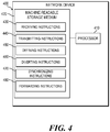
- FIG. 4 is a block diagram of an example network device to provide dedicated virtual local area network for peer-to-peer traffic transmitted between switches.
- a network device may be implemented, at least in part, by a combination of hardware and programming.
- the hardware may comprise at least one processor (e.g., processor 410) and the programming may comprise instructions, executable by the processor(s), stored on at least one machine-readable storage medium (e.g., 420).
- a network device may also include embedded memory and a software that can be executed in a host system and serve as a driver of the embedded memory.
- a "processor” may be at least one of a central processing unit (CPU), a semiconductor-based microprocessor, a graphics processing unit (GPU), a field-programmable gate array (FPGA) configured to retrieve and execute instructions, other electronic circuitry suitable for the retrieval and execution instructions stored on a machine-readable storage medium, or a combination thereof.
- CPU central processing unit
- GPU graphics processing unit
- FPGA field-programmable gate array
- the at least one processor 410 may fetch, decode, and execute instructions stored on storage medium 420 to perform the functionalities described below in relation to receiving instructions 430, transmitting instructions 440, defining instructions 450, diverting instructions 460, synchronizing instructions 470, and forwarding instructions 480.
- the functionalities of any of the instructions of storage medium 420 may be implemented in the form of electronic circuitry, in the form of executable instructions encoded on a machine-readable storage medium, or a combination thereof.
- the storage medium may be located either in the computing device executing the machine-readable instructions, or remote from but accessible to the computing device (e.g., via a computer network) for execution.
- storage medium 420 may be implemented by one machine-readable storage medium, or multiple machine-readable storage media.
- network device 400 includes at least one processor 410 and machine-readable storage medium 420, it may also include other suitable components, such as additional processing component(s) (e.g., processor(s), ASIC(s), etc.), storage (e.g., storage drive(s), etc.), or a combination thereof.
- additional processing component(s) e.g., processor(s), ASIC(s), etc.
- storage e.g., storage drive(s), etc.
- a "machine-readable storage medium” may be any electronic, magnetic, optical, or other physical storage apparatus to contain or store information such as executable instructions, data, and the like.
- any machine-readable storage medium described herein may be any of Random Access Memory (RAM), volatile memory, non-volatile memory, flash memory, a storage drive (e.g., a hard drive), a solid state drive, any type of storage disc (e.g., a compact disc, a DVD, etc.), and the like, or a combination thereof.
- RAM Random Access Memory
- volatile memory volatile memory
- non-volatile memory flash memory
- a storage drive e.g., a hard drive
- solid state drive any type of storage disc (e.g., a compact disc, a DVD, etc.)
- any machine-readable storage medium described herein may be non-transitory.
- a machine-readable storage medium or media may be part of an article (or article of manufacture). An article or article of manufacture may refer to any manufactured single component or multiple components.
- instructions 430-480 may be executed by processor 410 to: defining a source virtual local area network (VLAN), wherein the source VLAN is common for at least a first switch and a second switch, and wherein the source VLAN is dedicated to a particular link between the first switch and the second switch; using an Internet Protocol (IP) address corresponding to the defined source VLAN as a source address for peer-to-peer traffic transmitted between the first switch and the second switch, wherein no peer-to-peer traffic between the first switch and the second switch is transmitted over a link other than the particular link; diverting traffic through the particular link to be routed upstream via the peer uplink based on a plurality of network policies; synchronizing dynamic host configuration protocol (DHCP) leases corresponding to client devices served by the first switch and the second switch in response to a DHCP failure; forwarding traffic from the first switch to the second switch through the particular link, wherein a first load on the first switch is high, and wherein a second load on the second switch is low; etc.
- IP
Landscapes
- Engineering & Computer Science (AREA)
- Computer Networks & Wireless Communication (AREA)
- Signal Processing (AREA)
- Computer Security & Cryptography (AREA)
- Data Exchanges In Wide-Area Networks (AREA)
Abstract
Description
- A software-defined networking in a wide area network (SD-WAN) may simplify management and operation of a wide area network (WAN) by separating the networking hardware from its control mechanism. SD-WAN allows enterprises to build high-performance WANs using lower-cost network access replacing private WAN connection technologies such as multiprotocol label switching (MPLS). Gateway controllers can be deployed at the branch offices in a SD-WAN solution. Redundancy of gateway peers are usually provided so that the gateway branch controllers can be highly available. Also, traffic can be load balanced across the redundant gateway peers.
- The following detailed description references the drawings, wherein:
-
FIG. 1 is a block diagram of an example system deployment for dedicated virtual local area network for peer-to-peer traffic transmitted between switches; -
FIG. 2 is a block diagram illustrating an example peer-to-peer traffic packet transmitted between switches on a dedicated virtual local area network; -
FIG. 3 is a flowchart of an example process of providing dedicated virtual local area network for peer-to-peer traffic transmitted between switches; and -
FIG. 4 is a block diagram of an example network device to provide dedicated virtual local area network for peer-to-peer traffic transmitted between switches. - An example SD-WAN branch deployment may include a plurality of branch gateway controller peers that are highly available to provide redundancies for the gateway peers. The branch gateway peers can provide uplink connectivity, traffic load balancing, policy-based routing, etc. In addition, traffic load are balanced among at least two branch gateway peers. To provide redundancy for each other, these two branch gateway peers may be connected through a network switch. In some embodiments, they can operate in an active-active model to service branch wireless and wired clients. For example, in an active-active model, about half of the client devices in the network may terminate on a first branch gateway peer, and the other half of the network client devices in the network may terminate on a second branch gateway peer. Each gateway peer may be connected with an access point.
- Although peer-to-peer traffic could be routed through in an alternative path via a layer-2 switch, a direct peer-to-peer link may be used for one-to-one communications across the branch gateway controller peers. Peer-to-peer traffic can be enforced to pass through the direct link between the branch gateway controller peers in order to achieve better throughput, efficiency, and prioritization.
-
FIG. 1 is a block diagram of an example system deployment for dedicated virtual local area network for peer-to-peer traffic transmitted between switches.FIG 1 includes two branch gateway peers, such as,branch gateway peer 1 130 andbranch gateway peer 2 135. Although two branch gateway peers are illustrated here, an example branch deployment may have more than two branch gateway peers. - Each branch gateway peer (130 or 135) has an uplink connection that may connect to an Internet Service Provider (ISP). In this example,
branch gateway peer 1 130 is connected to ISP1 110, andbranch gateway peer 2 135 is connected toISP2 115. An ISP generally refers to an entity that provides enterprises or individual users with access to the Internet and other related services. The ISP has the equipment and the telecommunication line access required to have a point-of-presence on the Internet for the geographic area served. - Also,
branch gateway peers AP2 182, ... APn 188) deployed in the example branch network. The plurality of APs 180-188 may be connected to ports of at least one Layer-2 switch in the network switch via wired connections. - As used herein, "network device" generally includes a device that is adapted to transmit and/or receive signaling and to process information within such signaling such as a station (e.g., any data processing equipment such as a computer, cellular phone, personal digital assistant, tablet devices, etc.), an access point, data transfer devices (such as network switches, routers, controllers, etc.) or the like. For example, a "network device may refer to a network controller that comprises a hardware or a combination of hardware and software that enables connection between client devices and computer networks. In some implementations, a network device may refer to a server computing device (e.g., on-premise server, private, public, or hybrid cloud server) that comprises a hardware or a combination of hardware and software that can process and/or display network-related information. In some implementations, a network device may refer to an access point acting as a virtual master network controller among a cluster of access points.
- As used herein, 'access point' (AP) generally refers to receiving points for any known or convenient wireless access technology which may later become known. Specifically, the term AP is not intended to be limited to IEEE 802.11-based APs. APs generally function as an electronic device that is adapted to allow wireless devices to connect to a wired network via various communications standards.
-
Branch gateway peer 1 130 andbranch gateway peer 135 provides redundancy for each other. In some examples, one half of the clients in the network are managed bybranch gateway peer 1 130, while the other half of the clients in the network are managed bybranch gateway peer2 135. In the event thatbranch gateway peer 1 fails,branch gateway peer 2 135, as the backup peer, would manage the half of the clients previously managed bybranch gateway peer 1 130, and vice versa. - Furthermore, traffic between ISP1 110 and
branch gateway peer 1 130 are transmitted on uplink virtual local area network (VLAN) 120 associated with ISP1 110. On the other hand, traffic betweenISP2 115 andbranch gateway peer 2 135 are transmitted onuplink VLAN 125 associated withISP2 115. As used herein, a VLAN may generally refer to a logical group of workstations, servers and network devices that appear to be on the same LAN despite their geographical distribution. A VLAN can allow a network of computers and users to communicate in a simulated environment as if they exist in a single LAN and are sharing a single broadcast and multicast domain. VLANs are implemented to achieve scalability, security and ease of network management and can quickly adapt to changes in network requirements and relocation of workstations and server nodes. InFIG. 1 ,configuration 152 shows an example configuration foruplink VLAN 120. In this example,VLAN 1 120 has an address space of 1.1.1.1/24. In one example,VLAN 1 120 may be a VLAN dedicated to transmit traffic to and from devices associated with employees of an organization. Also,configuration 158 shows an example configuration foruplink VLAN 125. In this example,VLAN 5 125 has an address space of 5.5.5.2/24. In one example,VLAN 5 125 may be a VLAN dedicated to transmit traffic to and from devices associated with guests of the organization. - In this branch deployment, there can be both a
routing path 165 and abridging path 148 that are established betweenbranch gateway peer 1 130 andbranch gateway peer 2 135 for peer-to-peer traffics. Specifically,routing path 165 can be used to transmit traffic betweenbranch gateway peers router 1 150, at least one Layer-2switch 170, androuter 2 160. Here,router 1 150 is connected to atrunk port 142 ofbranch gateway peer 1 130 where user VLANs are allowed. Similarly,router 2 160 is connected to atrunk port 144 ofbranch gateway peer 2 135 where user VLANs are allowed.Trunk ports router 1 150 is configured with VLAN address 3.3.3.1/24 androuter 2 160 is configured with VLAN address 4 .4 .4 .1/24. - In some examples, the system may be configured with policy-based routing schemes. For instance, a policy may state that traffic to or from client devices associated with employees of the organization is transmitted through
branch gateway peer 1 130. However, if a client device associated with an employee has been authenticated into the network, then traffic to and from the authenticated client device may be transmitted throughbranch gateway peer 2 135. - In some examples, the system may inspect the traffic to determine whether the traffic belongs to a high priority. If the system determines that the traffic belongs to the high priority, the traffic is transmitted through
branch gateway peer 1 130. However, if the system determines that the traffic does not belong to a high priority, then the traffic is transmitted throughbranch gateway peer 2 135. - As shown in the above examples, the traffic often needs to be transmitted between
branch gateway peer 1 130 andbranch gateway peer 2 135. In some examples, peer-to-peer traffic can be routed viarouting path 165 frombranch gateway peer 1 130 to or frombranch gateway peer 2 135 at the address of 5.5.5.0/24 with a next hop address of 3.3.3.1. Note thatrouter 1 150 can route the peer-to-peer traffic in two directions. For example, for traffic to branchgateway peer 2 135,router 1 150 can route it to VLAN 5.5.5.0/24 with next hop address of 4 . 4 . 4 .1, which corresponds to the IP address ofrouter 2 160; for traffic to branchgateway peer 1 130,router 1 150 can route it to VLAN 1.1.1.0/24 with next hop address of 1.1.1.1, which corresponds to the IP address ofbranch gateway peer 1 130. Similarly,router 2 160 can route the peer-to-peer traffic in two directions. For traffic tobranch gateway peer 2 135,router 2 160 can route it to VLAN 5.5.5.0/24 with next hop address of 5.5.5.2, which corresponds to the IP address ofbranch gateway peer 2 135; for traffic to branchgateway peer 1 130,router 2 160 can route it to VLAN 1.1.1.0/24 with next hop address of 3.3.3.1, which corresponds to the IP address ofrouter 1 150. The IP addresses and next hop addresses mentioned above can be stored in a routing table atrouter 1 150 androuter 2 160. - On the other hand, traffic between
branch gateway peer 1 130 andbranch gateway peer 2 135 can also be transmitted without routing through bridgingpath 148. Specifically, the peer-to-peer traffic can be transmitted via a dedicatedinter-switch link 140. Because Interswitch link 140 here is dedicated for the peer-to-peer traffic, it allows traffic to be transmitted with low latency and high bandwidth. InFIG. 1 , interswitch link 140 directly connectsport 132 ofbranch gateway peer 1 130 andport 134 ofbranch gateway peer 2 135. - Even though there are two alternative paths, e.g., a
routing path 165 and aswitching path 148, for transmitting peer-to-peer traffic between the two branch gateway peers, transmitting the peer-to-peer traffic exclusively on switchingpath 148 results in lower latency and higher throughput than on routingpath 165 exclusively or using both paths. In order to transmit peer-to-peer traffic exclusively on bridgingpath 148, examples of the present disclosure use specific configurations on branch gateway peers. A particular VLAN (e.g., VLAN 2) is the single VLAN configured on bothaccess port 132 andaccess port 134 and dedicated for peer-to-peer traffic betweenbranch gateway peer 1 130 andbranch gateway peer 2 135. Unlike a trunk port, an access port allows traffic with a specific VLAN identifier to pass through and blocks all other traffics, including untagged traffic and traffic with other VLAN identifiers. As a result, when network traffic is sourced fromVLAN 2 and destined toVLAN 2, it is transmitted over bridgingpath 148. In the example illustrated inFIG. 1 , the peer-to-peer packets are sourced from the IP address of 2 .2 .2 .2 and destined to the IP address of 2.2.2.3. Note that, here, the subnet 2.2.2.2/24 or 2.2.2.3/24 each is a connected interface. Also, the single VLAN (e.g., VLAN2) using the same subnet is configured on access port 0/0/3 of both branch gateway peers that terminatesinterswitch link 140. Such configuration can ensure that the peer-to-peer traffic is transmitted through bridgingpath 148, straight into the interswitch link port 0/0/3, and at the same time, avoid transmitting peer-to-peer traffic throughrouting path 165. In other words, no peer-to-peer traffic is transmitted throughrouting path 165 with the configuration disclosed herein. The exclusive transmission of peer-to-peer traffic on switchingpath 148 can provide low latency and high throughput -
FIG. 2 is a block diagram illustrating an example peer-to-peer traffic packet transmitted between switches on a dedicated virtual local area network. Note that certain headers may be added to a peer-to-peer packet to ensure that the packet is transmitted through the bridging path and not the routing path when both paths are available in the network. Specifically, the example peer-to-peer traffic packet may include inter-switch link VLAN IP addresses 210, a client Media Access Control (MAC)address 240, astart time 250, anend time 260, a state oflease 270, etc. Further, inter-switch VLAN IP addresses 210 may include asource IP address 220 indicating the IP address of the source from which the peer-to-peer packet is transmitted, and adestination IP address 230 indicating the IP address of the destination to which the peer-to-peer packet is transmitted. As discussed above, for peer-to-peer traffic, a branch gateway peer may use a specific set of headers, including but not limited to sourceIP address 220 anddestination IP address 230, to the peer-to-peer packet. Thesource IP address 220 and thedestination IP address 230 belong to the same VLAN (e.g., VLAN 2) that is dedicated to the peer-to-peer traffic between the two branch gateway peers. -
Client MAC address 240 may uniquely identify a client device that the packet corresponds to. Starttime 250 may indicate a dynamic host configuration protocol (DHCP) lease start time corresponding to the client device with theMAC address 240.End time 260 may indicate a DHCP lease end time corresponding to the client device. - The dedicated VLAN over the interswitch link can be used in other scenarios too. In some examples, high throughput device-to-device communications can be transmitted over the dedicated VLAN over the interswitch link. Such device-to-device communication may include high availability control data, for example, data about sessions, routes, client states, etc. The device-to-device communication may also include data traffic that are redirected from device to device for multiple reasons, including but not limited to, load balancing, redirect policies, etc.
- In some examples, a database sync module (e.g., dbsync) may use the dedicated VLAN over the interswitch link to communicate information, such as, white list database, authentication details, etc.
- In some examples, the dedicated VLAN over the interswitch link described herein can communicate information among network controllers in a controller cluster. For examples, the network controllers within the same controller cluster may communicate with each other client state synchronization information, which may include but is not limited to, authentication keys, role, access control list (ACL) information, WLAN protocol transmit/receive (Tx/Rx) counters etc.
- In some examples, the dedicated VLAN over the interswitch link can be used to transmit firewall visibility data across redundant gateway devices to handle failover. In addition, the dedicated VLAN over the interswitch link can also be used to synchronize route table, forwarding rules, and/or other high availability data-plane or control-plane data.
-
FIG. 3 is a flowchart of an example process of providing dedicated virtual local area network for peer-to-peer traffic transmitted between switches. During operations, a network device (such as, the branch gateway controller) can define a source virtual local area network (VLAN), wherein the source VLAN is common for at least a first switch and a second switch, and wherein the source VLAN is dedicated to a particular link between the first switch and the second switch (operation 310). Furthermore, the network device can use an Internet Protocol (IP) address corresponding to the defined source VLAN as a source address for peer-to-peer traffic transmitted between the first switch and the second switch, wherein no peer-to-peer traffic between the first switch and the second switch is transmitted over a link other than the particular link (operation 320). - In some examples, the source VLAN can be locally connected. In some examples, a first single port of the first switch can be attached to the source VLAN. Also, a second single port of the second switch can be attached to the source VLAN.
- In some examples, the network device can divert traffic through the particular link to be routed upstream via the peer uplink based on a plurality of network policies.
- In some examples, the network device can synchronize dynamic host configuration protocol (DHCP) leases corresponding to client devices served by the first switch and the second switch in response to a DHCP failure.
- In some examples, the network device can forward traffic from the first switch to the second switch through the particular link. Here, a first load on the first switch may be high, and a second load on the second switch may be low.
-
FIG. 4 is a block diagram of an example network device to provide dedicated virtual local area network for peer-to-peer traffic transmitted between switches. - As used herein, a network device may be implemented, at least in part, by a combination of hardware and programming. For example, the hardware may comprise at least one processor (e.g., processor 410) and the programming may comprise instructions, executable by the processor(s), stored on at least one machine-readable storage medium (e.g., 420). In addition, a network device may also include embedded memory and a software that can be executed in a host system and serve as a driver of the embedded memory. As used herein, a "processor" may be at least one of a central processing unit (CPU), a semiconductor-based microprocessor, a graphics processing unit (GPU), a field-programmable gate array (FPGA) configured to retrieve and execute instructions, other electronic circuitry suitable for the retrieval and execution instructions stored on a machine-readable storage medium, or a combination thereof.
- The at least one
processor 410 may fetch, decode, and execute instructions stored onstorage medium 420 to perform the functionalities described below in relation to receivinginstructions 430, transmittinginstructions 440, defininginstructions 450, divertinginstructions 460, synchronizinginstructions 470, and forwardinginstructions 480. In other examples, the functionalities of any of the instructions ofstorage medium 420 may be implemented in the form of electronic circuitry, in the form of executable instructions encoded on a machine-readable storage medium, or a combination thereof. The storage medium may be located either in the computing device executing the machine-readable instructions, or remote from but accessible to the computing device (e.g., via a computer network) for execution. In the example ofFIG. 4 ,storage medium 420 may be implemented by one machine-readable storage medium, or multiple machine-readable storage media. - Although
network device 400 includes at least oneprocessor 410 and machine-readable storage medium 420, it may also include other suitable components, such as additional processing component(s) (e.g., processor(s), ASIC(s), etc.), storage (e.g., storage drive(s), etc.), or a combination thereof. - As used herein, a "machine-readable storage medium" may be any electronic, magnetic, optical, or other physical storage apparatus to contain or store information such as executable instructions, data, and the like. For example, any machine-readable storage medium described herein may be any of Random Access Memory (RAM), volatile memory, non-volatile memory, flash memory, a storage drive (e.g., a hard drive), a solid state drive, any type of storage disc (e.g., a compact disc, a DVD, etc.), and the like, or a combination thereof. Further, any machine-readable storage medium described herein may be non-transitory. In examples described herein, a machine-readable storage medium or media may be part of an article (or article of manufacture). An article or article of manufacture may refer to any manufactured single component or multiple components.
- Specifically, instructions 430-480 may be executed by
processor 410 to: defining a source virtual local area network (VLAN), wherein the source VLAN is common for at least a first switch and a second switch, and wherein the source VLAN is dedicated to a particular link between the first switch and the second switch; using an Internet Protocol (IP) address corresponding to the defined source VLAN as a source address for peer-to-peer traffic transmitted between the first switch and the second switch, wherein no peer-to-peer traffic between the first switch and the second switch is transmitted over a link other than the particular link; diverting traffic through the particular link to be routed upstream via the peer uplink based on a plurality of network policies; synchronizing dynamic host configuration protocol (DHCP) leases corresponding to client devices served by the first switch and the second switch in response to a DHCP failure; forwarding traffic from the first switch to the second switch through the particular link, wherein a first load on the first switch is high, and wherein a second load on the second switch is low; etc.
Claims (15)
- A method comprising:defining, by a network device, a source virtual local area network (VLAN), wherein the source VLAN is common for at least a first switch and a second switch, and wherein the source VLAN is dedicated to a particular link between the first switch and the second switch;using an Internet Protocol (IP) address corresponding to the defined source VLAN as a source address for peer-to-peer traffic transmitted between the first switch and the second switch, wherein no peer-to-peer traffic between the first switch and the second switch is transmitted over a link other than the particular link.
- The method of claim 1, wherein the source VLAN is locally connected or wherein a first single port of the first switch is attached to the source VLAN.
- The method of claim 2, wherein a second single port of the second switch is attached to the source VLAN.
- The method of claim 1, further comprising:
diverting traffic through the particular link to be routed upstream via the peer uplink based on a plurality of network policies. - The method of claim 1, further comprising:
synchronizing dynamic host configuration protocol (DHCP) leases corresponding to client devices served by the first switch and the second switch in response to a DHCP failure. - The method of claim 1, further comprising:
forwarding traffic from the first switch to the second switch through the particular link, wherein a first load on the first switch is high, and wherein a second load on the second switch is low. - A network device, comprising at least:a memory;a processor executing instructions from the memory to:define a source virtual local area network (VLAN), wherein the source VLAN is common for at least a first switch and a second switch, and wherein the source VLAN is dedicated to a particular link between the first switch and the second switch; anduse an Internet Protocol (IP) address corresponding to the defined source VLAN as a source address for peer-to-peer traffic transmitted between the first switch and the second switch, wherein no peer-to-peer traffic between the first switch and the second switch is transmitted over a link other than the particular link.
- The network device of claim 7, wherein the source VLAN is locally connected, or wherein a first single port of the first switch is attached to the source VLAN.
- The network device of claim 8, wherein a second single port of the second switch is attached to the source VLAN.
- The network device of claim 7, wherein the processor further executes the instructions from the memory to:
divert traffic through the particular link to be routed upstream via the peer uplink based on a plurality of network policies. - The network device of claim 7, wherein the processor further executes the instructions from the memory to:
synchronize dynamic host configuration protocol (DHCP) leases corresponding to client devices served by the first switch and the second switch in response to a DHCP failure. - The network device of claim 7, wherein the processor further executes the instructions from the memory to:
forward traffic from the first switch to the second switch through the particular link, wherein a first load on the first switch is high, and wherein a second load on the second switch is low. - A non-transitory machine-readable storage medium encoded with instructions executable by at least one processor of a network device, the machine-readable storage medium comprising instructions to:define a source virtual local area network (VLAN), wherein the source VLAN is common for at least a first switch and a second switch, and wherein the source VLAN is dedicated to a particular link between the first switch and the second switch; anduse an Internet Protocol (IP) address corresponding to the defined source VLAN as a source address for peer-to-peer traffic transmitted between the first switch and the second switch, wherein no peer-to-peer traffic between the first switch and the second switch is transmitted over a link other than the particular link.
- The non-transitory machine-readable storage medium of claim 13, wherein:the source VLAN is locally connected; ora first single port of the first switch is attached to the source VLAN, and wherein a second single port of the second switch is attached to the source VLAN.
- The non-transitory machine-readable storage medium of claim 13, wherein the machine-readable storage medium further comprises instructions to:divert traffic through the particular link to be routed upstream via the peer uplink based on a plurality of network policies,and wherein the machine-readable storage medium optionally futher comprises instructions to:synchronize dynamic host configuration protocol (DHCP) leases corresponding to client devices served by the first switch and the second switch in response to a DHCP failure; orforward traffic from the first switch to the second switch through the particular link, wherein a first load on the first switch is high, and wherein a second load on the second switch is low.
Applications Claiming Priority (1)
| Application Number | Priority Date | Filing Date | Title |
|---|---|---|---|
| US15/884,585 US10673781B2 (en) | 2018-01-31 | 2018-01-31 | Dedicated virtual local area network for peer-to-peer traffic transmitted between switches |
Publications (2)
| Publication Number | Publication Date |
|---|---|
| EP3522457A1 true EP3522457A1 (en) | 2019-08-07 |
| EP3522457B1 EP3522457B1 (en) | 2020-06-24 |
Family
ID=65199319
Family Applications (1)
| Application Number | Title | Priority Date | Filing Date |
|---|---|---|---|
| EP19152849.6A Active EP3522457B1 (en) | 2018-01-31 | 2019-01-21 | Dedicated virtual local area network for peer-to-peer traffic transmitted between switches |
Country Status (3)
| Country | Link |
|---|---|
| US (1) | US10673781B2 (en) |
| EP (1) | EP3522457B1 (en) |
| CN (1) | CN110098992B (en) |
Families Citing this family (40)
| Publication number | Priority date | Publication date | Assignee | Title |
|---|---|---|---|---|
| US10454714B2 (en) | 2013-07-10 | 2019-10-22 | Nicira, Inc. | Method and system of overlay flow control |
| US10498652B2 (en) | 2015-04-13 | 2019-12-03 | Nicira, Inc. | Method and system of application-aware routing with crowdsourcing |
| US10425382B2 (en) | 2015-04-13 | 2019-09-24 | Nicira, Inc. | Method and system of a cloud-based multipath routing protocol |
| US10135789B2 (en) | 2015-04-13 | 2018-11-20 | Nicira, Inc. | Method and system of establishing a virtual private network in a cloud service for branch networking |
| US11706127B2 (en) | 2017-01-31 | 2023-07-18 | Vmware, Inc. | High performance software-defined core network |
| US20200036624A1 (en) | 2017-01-31 | 2020-01-30 | The Mode Group | High performance software-defined core network |
| US20180219765A1 (en) | 2017-01-31 | 2018-08-02 | Waltz Networks | Method and Apparatus for Network Traffic Control Optimization |
| US10992568B2 (en) | 2017-01-31 | 2021-04-27 | Vmware, Inc. | High performance software-defined core network |
| US10778528B2 (en) | 2017-02-11 | 2020-09-15 | Nicira, Inc. | Method and system of connecting to a multipath hub in a cluster |
| US10523539B2 (en) | 2017-06-22 | 2019-12-31 | Nicira, Inc. | Method and system of resiliency in cloud-delivered SD-WAN |
| US10999100B2 (en) | 2017-10-02 | 2021-05-04 | Vmware, Inc. | Identifying multiple nodes in a virtual network defined over a set of public clouds to connect to an external SAAS provider |
| US11115480B2 (en) | 2017-10-02 | 2021-09-07 | Vmware, Inc. | Layer four optimization for a virtual network defined over public cloud |
| US11516049B2 (en) | 2017-10-02 | 2022-11-29 | Vmware, Inc. | Overlay network encapsulation to forward data message flows through multiple public cloud datacenters |
| US11223514B2 (en) | 2017-11-09 | 2022-01-11 | Nicira, Inc. | Method and system of a dynamic high-availability mode based on current wide area network connectivity |
| DE112019006684T5 (en) * | 2019-01-17 | 2021-11-18 | Hewlett Packard Enterprise Development Lp | SHORT-TERM LEASE ASSIGNMENT TO REDUCE NETWORK ADDRESS CONFLICTS IN DHCP FAILURE DEPLOYMENT |
| US11310170B2 (en) | 2019-08-27 | 2022-04-19 | Vmware, Inc. | Configuring edge nodes outside of public clouds to use routes defined through the public clouds |
| US11044190B2 (en) | 2019-10-28 | 2021-06-22 | Vmware, Inc. | Managing forwarding elements at edge nodes connected to a virtual network |
| US11489783B2 (en) | 2019-12-12 | 2022-11-01 | Vmware, Inc. | Performing deep packet inspection in a software defined wide area network |
| US11394640B2 (en) | 2019-12-12 | 2022-07-19 | Vmware, Inc. | Collecting and analyzing data regarding flows associated with DPI parameters |
| US11722925B2 (en) | 2020-01-24 | 2023-08-08 | Vmware, Inc. | Performing service class aware load balancing to distribute packets of a flow among multiple network links |
| US11296947B2 (en) | 2020-06-29 | 2022-04-05 | Star2Star Communications, LLC | SD-WAN device, system, and network |
| US11245641B2 (en) * | 2020-07-02 | 2022-02-08 | Vmware, Inc. | Methods and apparatus for application aware hub clustering techniques for a hyper scale SD-WAN |
| US11709710B2 (en) | 2020-07-30 | 2023-07-25 | Vmware, Inc. | Memory allocator for I/O operations |
| US11575591B2 (en) | 2020-11-17 | 2023-02-07 | Vmware, Inc. | Autonomous distributed forwarding plane traceability based anomaly detection in application traffic for hyper-scale SD-WAN |
| US11575600B2 (en) | 2020-11-24 | 2023-02-07 | Vmware, Inc. | Tunnel-less SD-WAN |
| US11601356B2 (en) | 2020-12-29 | 2023-03-07 | Vmware, Inc. | Emulating packet flows to assess network links for SD-WAN |
| US11792127B2 (en) | 2021-01-18 | 2023-10-17 | Vmware, Inc. | Network-aware load balancing |
| US11979325B2 (en) | 2021-01-28 | 2024-05-07 | VMware LLC | Dynamic SD-WAN hub cluster scaling with machine learning |
| US12009987B2 (en) | 2021-05-03 | 2024-06-11 | VMware LLC | Methods to support dynamic transit paths through hub clustering across branches in SD-WAN |
| US11509571B1 (en) | 2021-05-03 | 2022-11-22 | Vmware, Inc. | Cost-based routing mesh for facilitating routing through an SD-WAN |
| US11729065B2 (en) | 2021-05-06 | 2023-08-15 | Vmware, Inc. | Methods for application defined virtual network service among multiple transport in SD-WAN |
| US11489720B1 (en) | 2021-06-18 | 2022-11-01 | Vmware, Inc. | Method and apparatus to evaluate resource elements and public clouds for deploying tenant deployable elements based on harvested performance metrics |
| US12015536B2 (en) | 2021-06-18 | 2024-06-18 | VMware LLC | Method and apparatus for deploying tenant deployable elements across public clouds based on harvested performance metrics of types of resource elements in the public clouds |
| US12047282B2 (en) | 2021-07-22 | 2024-07-23 | VMware LLC | Methods for smart bandwidth aggregation based dynamic overlay selection among preferred exits in SD-WAN |
| US11375005B1 (en) | 2021-07-24 | 2022-06-28 | Vmware, Inc. | High availability solutions for a secure access service edge application |
| US11943146B2 (en) | 2021-10-01 | 2024-03-26 | VMware LLC | Traffic prioritization in SD-WAN |
| US11909815B2 (en) | 2022-06-06 | 2024-02-20 | VMware LLC | Routing based on geolocation costs |
| US11818208B1 (en) * | 2022-08-05 | 2023-11-14 | International Business Machines Corporation | Adaptive data protocol for IoT devices |
| US12057993B1 (en) | 2023-03-27 | 2024-08-06 | VMware LLC | Identifying and remediating anomalies in a self-healing network |
| US12034587B1 (en) | 2023-03-27 | 2024-07-09 | VMware LLC | Identifying and remediating anomalies in a self-healing network |
Citations (4)
| Publication number | Priority date | Publication date | Assignee | Title |
|---|---|---|---|---|
| WO2004032426A1 (en) * | 2002-10-04 | 2004-04-15 | Telefonaktiebolaget Lm Ericsson (Publ.) | Isolation of hosts connected to an access network |
| US20070237148A1 (en) * | 2006-04-10 | 2007-10-11 | Khalil Jabr | Method for IP routing when using dynamic VLANs with web based authentication |
| US20130124750A1 (en) * | 2011-11-16 | 2013-05-16 | Force 10 Networks, Inc. | Network virtualization without gateway function |
| US20140269648A1 (en) * | 2013-03-14 | 2014-09-18 | Aruba Networks, Inc. | Distributed Network Layer Mobility for Unified Access Networks |
Family Cites Families (14)
| Publication number | Priority date | Publication date | Assignee | Title |
|---|---|---|---|---|
| EP1854250B1 (en) | 2005-02-28 | 2011-09-21 | International Business Machines Corporation | Blade server system with at least one rack-switch having multiple switches interconnected and configured for management and operation as a single virtual switch |
| US9391796B1 (en) | 2010-12-22 | 2016-07-12 | Juniper Networks, Inc. | Methods and apparatus for using border gateway protocol (BGP) for converged fibre channel (FC) control plane |
| US8837499B2 (en) | 2011-05-14 | 2014-09-16 | International Business Machines Corporation | Distributed fabric protocol (DFP) switching network architecture |
| US9019813B2 (en) * | 2013-01-30 | 2015-04-28 | International Business Machines Corporation | Active IP forwarding in an event driven virtual link aggregation (VLAG) system |
| US8964530B2 (en) * | 2013-01-31 | 2015-02-24 | Cisco Technology, Inc. | Increasing multi-destination scale in a network environment |
| CN104601427B (en) * | 2013-10-31 | 2018-03-06 | 新华三技术有限公司 | Message forwarding method and device in data center network |
| US9479349B2 (en) * | 2013-12-31 | 2016-10-25 | Lenovo Enterprise Solutions (Singapore) Pte. Ltd | VLAG PIM multicast traffic load balancing |
| US9531591B2 (en) * | 2014-03-23 | 2016-12-27 | Avaya Inc. | Configuration of networks using switch device access of remote server |
| US9544219B2 (en) | 2014-07-31 | 2017-01-10 | Brocade Communications Systems, Inc. | Global VLAN services |
| US20160094442A1 (en) * | 2014-09-26 | 2016-03-31 | Lenovo Enterprise Solutions (Singapore) Pte. Ltd. | Protocol independent multicast (pim) register message transmission |
| CN105450532B (en) * | 2014-09-28 | 2018-10-09 | 新华三技术有限公司 | Three-layer forwarding method in software defined network and device |
| US10298489B2 (en) * | 2015-07-24 | 2019-05-21 | International Business Machines Corporation | Adding multi-tenant awareness to a network packet processing device on a software defined network (SDN) |
| US10263840B2 (en) * | 2016-05-24 | 2019-04-16 | Microsoft Technology Licensing, Llc | Subnet stretching via layer three communications |
| US10425325B2 (en) * | 2017-10-30 | 2019-09-24 | Dell Products Lp | Optimizing traffic paths to orphaned hosts in VXLAN networks using virtual link trunking-based multi-homing |
-
2018
- 2018-01-31 US US15/884,585 patent/US10673781B2/en active Active
-
2019
- 2019-01-21 EP EP19152849.6A patent/EP3522457B1/en active Active
- 2019-01-31 CN CN201910097956.0A patent/CN110098992B/en active Active
Patent Citations (4)
| Publication number | Priority date | Publication date | Assignee | Title |
|---|---|---|---|---|
| WO2004032426A1 (en) * | 2002-10-04 | 2004-04-15 | Telefonaktiebolaget Lm Ericsson (Publ.) | Isolation of hosts connected to an access network |
| US20070237148A1 (en) * | 2006-04-10 | 2007-10-11 | Khalil Jabr | Method for IP routing when using dynamic VLANs with web based authentication |
| US20130124750A1 (en) * | 2011-11-16 | 2013-05-16 | Force 10 Networks, Inc. | Network virtualization without gateway function |
| US20140269648A1 (en) * | 2013-03-14 | 2014-09-18 | Aruba Networks, Inc. | Distributed Network Layer Mobility for Unified Access Networks |
Also Published As
| Publication number | Publication date |
|---|---|
| CN110098992A (en) | 2019-08-06 |
| CN110098992B (en) | 2022-01-07 |
| US20190238483A1 (en) | 2019-08-01 |
| EP3522457B1 (en) | 2020-06-24 |
| US10673781B2 (en) | 2020-06-02 |
Similar Documents
| Publication | Publication Date | Title |
|---|---|---|
| EP3522457B1 (en) | Dedicated virtual local area network for peer-to-peer traffic transmitted between switches | |
| CN112840625B (en) | First hop migration gateway redundancy in a network computing environment | |
| US10779339B2 (en) | Wireless roaming using a distributed store | |
| US8694664B2 (en) | Active-active multi-homing support for overlay transport protocol | |
| US8948181B2 (en) | System and method for optimizing next-hop table space in a dual-homed network environment | |
| US8817593B2 (en) | Method and apparatus providing failover for a point to point tunnel for wireless local area network split-plane environments | |
| US9497073B2 (en) | Distributed link aggregation group (LAG) for a layer 2 fabric | |
| US8730793B2 (en) | Method and apparatus providing network redundancy and high availability to remote network nodes | |
| US9258185B2 (en) | Fibre channel over Ethernet support in a trill network environment | |
| US20150043348A1 (en) | Traffic Flow Redirection between Border Routers using Routing Encapsulation | |
| US10721211B2 (en) | Hierarchical clustering in a geographically dispersed network environment | |
| CN110061915B (en) | Method and system for virtual link aggregation across multiple fabric switches | |
| US20170013452A1 (en) | Network re-convergence point | |
| EP3069471B1 (en) | Optimized multicast routing in a clos-like network | |
| US8446818B2 (en) | Routed split multi-link trunking resiliency for wireless local area network split-plane environments | |
| CN105812259A (en) | Packet forwarding method and device | |
| US8861339B2 (en) | Packet forwarding function of a mobility switch deployed as routed SMLT (RSMLT) node | |
| Banik et al. | Enabling distributed mobility management: A unified wireless network architecture based on virtualized core network | |
| CN116938809A (en) | Role information propagation in an access switch | |
| KR20130093767A (en) | Ipsec vpn system and method for supporing high availability |
Legal Events
| Date | Code | Title | Description |
|---|---|---|---|
| PUAI | Public reference made under article 153(3) epc to a published international application that has entered the european phase |
Free format text: ORIGINAL CODE: 0009012 |
|
| STAA | Information on the status of an ep patent application or granted ep patent |
Free format text: STATUS: THE APPLICATION HAS BEEN PUBLISHED |
|
| AK | Designated contracting states |
Kind code of ref document: A1 Designated state(s): AL AT BE BG CH CY CZ DE DK EE ES FI FR GB GR HR HU IE IS IT LI LT LU LV MC MK MT NL NO PL PT RO RS SE SI SK SM TR |
|
| AX | Request for extension of the european patent |
Extension state: BA ME |
|
| STAA | Information on the status of an ep patent application or granted ep patent |
Free format text: STATUS: REQUEST FOR EXAMINATION WAS MADE |
|
| 17P | Request for examination filed |
Effective date: 20200206 |
|
| RBV | Designated contracting states (corrected) |
Designated state(s): AL AT BE BG CH CY CZ DE DK EE ES FI FR GB GR HR HU IE IS IT LI LT LU LV MC MK MT NL NO PL PT RO RS SE SI SK SM TR |
|
| GRAP | Despatch of communication of intention to grant a patent |
Free format text: ORIGINAL CODE: EPIDOSNIGR1 |
|
| STAA | Information on the status of an ep patent application or granted ep patent |
Free format text: STATUS: GRANT OF PATENT IS INTENDED |
|
| INTG | Intention to grant announced |
Effective date: 20200330 |
|
| GRAS | Grant fee paid |
Free format text: ORIGINAL CODE: EPIDOSNIGR3 |
|
| GRAA | (expected) grant |
Free format text: ORIGINAL CODE: 0009210 |
|
| STAA | Information on the status of an ep patent application or granted ep patent |
Free format text: STATUS: THE PATENT HAS BEEN GRANTED |
|
| AK | Designated contracting states |
Kind code of ref document: B1 Designated state(s): AL AT BE BG CH CY CZ DE DK EE ES FI FR GB GR HR HU IE IS IT LI LT LU LV MC MK MT NL NO PL PT RO RS SE SI SK SM TR |
|
| REG | Reference to a national code |
Ref country code: GB Ref legal event code: FG4D |
|
| REG | Reference to a national code |
Ref country code: CH Ref legal event code: EP |
|
| REG | Reference to a national code |
Ref country code: DE Ref legal event code: R096 Ref document number: 602019000196 Country of ref document: DE |
|
| REG | Reference to a national code |
Ref country code: AT Ref legal event code: REF Ref document number: 1285008 Country of ref document: AT Kind code of ref document: T Effective date: 20200715 |
|
| REG | Reference to a national code |
Ref country code: IE Ref legal event code: FG4D |
|
| PG25 | Lapsed in a contracting state [announced via postgrant information from national office to epo] |
Ref country code: LT Free format text: LAPSE BECAUSE OF FAILURE TO SUBMIT A TRANSLATION OF THE DESCRIPTION OR TO PAY THE FEE WITHIN THE PRESCRIBED TIME-LIMIT Effective date: 20200624 Ref country code: SE Free format text: LAPSE BECAUSE OF FAILURE TO SUBMIT A TRANSLATION OF THE DESCRIPTION OR TO PAY THE FEE WITHIN THE PRESCRIBED TIME-LIMIT Effective date: 20200624 Ref country code: NO Free format text: LAPSE BECAUSE OF FAILURE TO SUBMIT A TRANSLATION OF THE DESCRIPTION OR TO PAY THE FEE WITHIN THE PRESCRIBED TIME-LIMIT Effective date: 20200924 Ref country code: GR Free format text: LAPSE BECAUSE OF FAILURE TO SUBMIT A TRANSLATION OF THE DESCRIPTION OR TO PAY THE FEE WITHIN THE PRESCRIBED TIME-LIMIT Effective date: 20200925 Ref country code: FI Free format text: LAPSE BECAUSE OF FAILURE TO SUBMIT A TRANSLATION OF THE DESCRIPTION OR TO PAY THE FEE WITHIN THE PRESCRIBED TIME-LIMIT Effective date: 20200624 |
|
| REG | Reference to a national code |
Ref country code: LT Ref legal event code: MG4D |
|
| PG25 | Lapsed in a contracting state [announced via postgrant information from national office to epo] |
Ref country code: HR Free format text: LAPSE BECAUSE OF FAILURE TO SUBMIT A TRANSLATION OF THE DESCRIPTION OR TO PAY THE FEE WITHIN THE PRESCRIBED TIME-LIMIT Effective date: 20200624 Ref country code: LV Free format text: LAPSE BECAUSE OF FAILURE TO SUBMIT A TRANSLATION OF THE DESCRIPTION OR TO PAY THE FEE WITHIN THE PRESCRIBED TIME-LIMIT Effective date: 20200624 Ref country code: BG Free format text: LAPSE BECAUSE OF FAILURE TO SUBMIT A TRANSLATION OF THE DESCRIPTION OR TO PAY THE FEE WITHIN THE PRESCRIBED TIME-LIMIT Effective date: 20200924 Ref country code: RS Free format text: LAPSE BECAUSE OF FAILURE TO SUBMIT A TRANSLATION OF THE DESCRIPTION OR TO PAY THE FEE WITHIN THE PRESCRIBED TIME-LIMIT Effective date: 20200624 |
|
| REG | Reference to a national code |
Ref country code: NL Ref legal event code: MP Effective date: 20200624 |
|
| REG | Reference to a national code |
Ref country code: AT Ref legal event code: MK05 Ref document number: 1285008 Country of ref document: AT Kind code of ref document: T Effective date: 20200624 |
|
| PG25 | Lapsed in a contracting state [announced via postgrant information from national office to epo] |
Ref country code: AL Free format text: LAPSE BECAUSE OF FAILURE TO SUBMIT A TRANSLATION OF THE DESCRIPTION OR TO PAY THE FEE WITHIN THE PRESCRIBED TIME-LIMIT Effective date: 20200624 Ref country code: NL Free format text: LAPSE BECAUSE OF FAILURE TO SUBMIT A TRANSLATION OF THE DESCRIPTION OR TO PAY THE FEE WITHIN THE PRESCRIBED TIME-LIMIT Effective date: 20200624 |
|
| PG25 | Lapsed in a contracting state [announced via postgrant information from national office to epo] |
Ref country code: CZ Free format text: LAPSE BECAUSE OF FAILURE TO SUBMIT A TRANSLATION OF THE DESCRIPTION OR TO PAY THE FEE WITHIN THE PRESCRIBED TIME-LIMIT Effective date: 20200624 Ref country code: RO Free format text: LAPSE BECAUSE OF FAILURE TO SUBMIT A TRANSLATION OF THE DESCRIPTION OR TO PAY THE FEE WITHIN THE PRESCRIBED TIME-LIMIT Effective date: 20200624 Ref country code: AT Free format text: LAPSE BECAUSE OF FAILURE TO SUBMIT A TRANSLATION OF THE DESCRIPTION OR TO PAY THE FEE WITHIN THE PRESCRIBED TIME-LIMIT Effective date: 20200624 Ref country code: IT Free format text: LAPSE BECAUSE OF FAILURE TO SUBMIT A TRANSLATION OF THE DESCRIPTION OR TO PAY THE FEE WITHIN THE PRESCRIBED TIME-LIMIT Effective date: 20200624 Ref country code: SM Free format text: LAPSE BECAUSE OF FAILURE TO SUBMIT A TRANSLATION OF THE DESCRIPTION OR TO PAY THE FEE WITHIN THE PRESCRIBED TIME-LIMIT Effective date: 20200624 Ref country code: EE Free format text: LAPSE BECAUSE OF FAILURE TO SUBMIT A TRANSLATION OF THE DESCRIPTION OR TO PAY THE FEE WITHIN THE PRESCRIBED TIME-LIMIT Effective date: 20200624 Ref country code: ES Free format text: LAPSE BECAUSE OF FAILURE TO SUBMIT A TRANSLATION OF THE DESCRIPTION OR TO PAY THE FEE WITHIN THE PRESCRIBED TIME-LIMIT Effective date: 20200624 Ref country code: PT Free format text: LAPSE BECAUSE OF FAILURE TO SUBMIT A TRANSLATION OF THE DESCRIPTION OR TO PAY THE FEE WITHIN THE PRESCRIBED TIME-LIMIT Effective date: 20201026 |
|
| PG25 | Lapsed in a contracting state [announced via postgrant information from national office to epo] |
Ref country code: SK Free format text: LAPSE BECAUSE OF FAILURE TO SUBMIT A TRANSLATION OF THE DESCRIPTION OR TO PAY THE FEE WITHIN THE PRESCRIBED TIME-LIMIT Effective date: 20200624 Ref country code: PL Free format text: LAPSE BECAUSE OF FAILURE TO SUBMIT A TRANSLATION OF THE DESCRIPTION OR TO PAY THE FEE WITHIN THE PRESCRIBED TIME-LIMIT Effective date: 20200624 Ref country code: IS Free format text: LAPSE BECAUSE OF FAILURE TO SUBMIT A TRANSLATION OF THE DESCRIPTION OR TO PAY THE FEE WITHIN THE PRESCRIBED TIME-LIMIT Effective date: 20201024 |
|
| REG | Reference to a national code |
Ref country code: DE Ref legal event code: R097 Ref document number: 602019000196 Country of ref document: DE |
|
| PG25 | Lapsed in a contracting state [announced via postgrant information from national office to epo] |
Ref country code: DK Free format text: LAPSE BECAUSE OF FAILURE TO SUBMIT A TRANSLATION OF THE DESCRIPTION OR TO PAY THE FEE WITHIN THE PRESCRIBED TIME-LIMIT Effective date: 20200624 |
|
| PLBE | No opposition filed within time limit |
Free format text: ORIGINAL CODE: 0009261 |
|
| STAA | Information on the status of an ep patent application or granted ep patent |
Free format text: STATUS: NO OPPOSITION FILED WITHIN TIME LIMIT |
|
| 26N | No opposition filed |
Effective date: 20210325 |
|
| PG25 | Lapsed in a contracting state [announced via postgrant information from national office to epo] |
Ref country code: MC Free format text: LAPSE BECAUSE OF FAILURE TO SUBMIT A TRANSLATION OF THE DESCRIPTION OR TO PAY THE FEE WITHIN THE PRESCRIBED TIME-LIMIT Effective date: 20200624 Ref country code: SI Free format text: LAPSE BECAUSE OF FAILURE TO SUBMIT A TRANSLATION OF THE DESCRIPTION OR TO PAY THE FEE WITHIN THE PRESCRIBED TIME-LIMIT Effective date: 20200624 |
|
| PG25 | Lapsed in a contracting state [announced via postgrant information from national office to epo] |
Ref country code: LU Free format text: LAPSE BECAUSE OF NON-PAYMENT OF DUE FEES Effective date: 20210121 |
|
| REG | Reference to a national code |
Ref country code: BE Ref legal event code: MM Effective date: 20210131 |
|
| PG25 | Lapsed in a contracting state [announced via postgrant information from national office to epo] |
Ref country code: FR Free format text: LAPSE BECAUSE OF NON-PAYMENT OF DUE FEES Effective date: 20210131 |
|
| PG25 | Lapsed in a contracting state [announced via postgrant information from national office to epo] |
Ref country code: IE Free format text: LAPSE BECAUSE OF NON-PAYMENT OF DUE FEES Effective date: 20210121 |
|
| PG25 | Lapsed in a contracting state [announced via postgrant information from national office to epo] |
Ref country code: BE Free format text: LAPSE BECAUSE OF NON-PAYMENT OF DUE FEES Effective date: 20210131 |
|
| REG | Reference to a national code |
Ref country code: CH Ref legal event code: PL |
|
| PG25 | Lapsed in a contracting state [announced via postgrant information from national office to epo] |
Ref country code: LI Free format text: LAPSE BECAUSE OF NON-PAYMENT OF DUE FEES Effective date: 20220131 Ref country code: CH Free format text: LAPSE BECAUSE OF NON-PAYMENT OF DUE FEES Effective date: 20220131 |
|
| REG | Reference to a national code |
Ref country code: DE Ref legal event code: R082 Ref document number: 602019000196 Country of ref document: DE Representative=s name: PROCK, THOMAS, DR., GB |
|
| REG | Reference to a national code |
Ref country code: DE Ref legal event code: R081 Ref document number: 602019000196 Country of ref document: DE Owner name: HEWLETT PACKARD ENTERPRISE DEVELOPMENT LP, SPR, US Free format text: FORMER OWNER: HEWLETT PACKARD ENTERPRISE DEVELOPMENT LP, HOUSTON, TEX., US |
|
| PG25 | Lapsed in a contracting state [announced via postgrant information from national office to epo] |
Ref country code: CY Free format text: LAPSE BECAUSE OF FAILURE TO SUBMIT A TRANSLATION OF THE DESCRIPTION OR TO PAY THE FEE WITHIN THE PRESCRIBED TIME-LIMIT Effective date: 20200624 |
|
| PG25 | Lapsed in a contracting state [announced via postgrant information from national office to epo] |
Ref country code: HU Free format text: LAPSE BECAUSE OF FAILURE TO SUBMIT A TRANSLATION OF THE DESCRIPTION OR TO PAY THE FEE WITHIN THE PRESCRIBED TIME-LIMIT; INVALID AB INITIO Effective date: 20190121 |
|
| PG25 | Lapsed in a contracting state [announced via postgrant information from national office to epo] |
Ref country code: MK Free format text: LAPSE BECAUSE OF FAILURE TO SUBMIT A TRANSLATION OF THE DESCRIPTION OR TO PAY THE FEE WITHIN THE PRESCRIBED TIME-LIMIT Effective date: 20200624 |
|
| PGFP | Annual fee paid to national office [announced via postgrant information from national office to epo] |
Ref country code: DE Payment date: 20240129 Year of fee payment: 6 Ref country code: GB Payment date: 20240123 Year of fee payment: 6 |
|
| PG25 | Lapsed in a contracting state [announced via postgrant information from national office to epo] |
Ref country code: MT Free format text: LAPSE BECAUSE OF FAILURE TO SUBMIT A TRANSLATION OF THE DESCRIPTION OR TO PAY THE FEE WITHIN THE PRESCRIBED TIME-LIMIT Effective date: 20200624 |