EP3522364A1 - Inverter - Google Patents
Inverter Download PDFInfo
- Publication number
- EP3522364A1 EP3522364A1 EP18166805.4A EP18166805A EP3522364A1 EP 3522364 A1 EP3522364 A1 EP 3522364A1 EP 18166805 A EP18166805 A EP 18166805A EP 3522364 A1 EP3522364 A1 EP 3522364A1
- Authority
- EP
- European Patent Office
- Prior art keywords
- inverter
- voltage
- output
- frequency
- reference frame
- Prior art date
- Legal status (The legal status is an assumption and is not a legal conclusion. Google has not performed a legal analysis and makes no representation as to the accuracy of the status listed.)
- Granted
Links
Images



Classifications
-
- H—ELECTRICITY
- H02—GENERATION; CONVERSION OR DISTRIBUTION OF ELECTRIC POWER
- H02M—APPARATUS FOR CONVERSION BETWEEN AC AND AC, BETWEEN AC AND DC, OR BETWEEN DC AND DC, AND FOR USE WITH MAINS OR SIMILAR POWER SUPPLY SYSTEMS; CONVERSION OF DC OR AC INPUT POWER INTO SURGE OUTPUT POWER; CONTROL OR REGULATION THEREOF
- H02M7/00—Conversion of AC power input into DC power output; Conversion of DC power input into AC power output
- H02M7/42—Conversion of DC power input into AC power output without possibility of reversal
- H02M7/44—Conversion of DC power input into AC power output without possibility of reversal by static converters
-
- H—ELECTRICITY
- H02—GENERATION; CONVERSION OR DISTRIBUTION OF ELECTRIC POWER
- H02P—CONTROL OR REGULATION OF ELECTRIC MOTORS, ELECTRIC GENERATORS OR DYNAMO-ELECTRIC CONVERTERS; CONTROLLING TRANSFORMERS, REACTORS OR CHOKE COILS
- H02P4/00—Arrangements specially adapted for regulating or controlling the speed or torque of electric motors that can be connected to two or more different electric power supplies
-
- B—PERFORMING OPERATIONS; TRANSPORTING
- B66—HOISTING; LIFTING; HAULING
- B66C—CRANES; LOAD-ENGAGING ELEMENTS OR DEVICES FOR CRANES, CAPSTANS, WINCHES, OR TACKLES
- B66C13/00—Other constructional features or details
- B66C13/18—Control systems or devices
- B66C13/22—Control systems or devices for electric drives
-
- B—PERFORMING OPERATIONS; TRANSPORTING
- B66—HOISTING; LIFTING; HAULING
- B66C—CRANES; LOAD-ENGAGING ELEMENTS OR DEVICES FOR CRANES, CAPSTANS, WINCHES, OR TACKLES
- B66C13/00—Other constructional features or details
- B66C13/18—Control systems or devices
- B66C13/22—Control systems or devices for electric drives
- B66C13/23—Circuits for controlling the lowering of the load
- B66C13/26—Circuits for controlling the lowering of the load by AC motors
-
- H—ELECTRICITY
- H02—GENERATION; CONVERSION OR DISTRIBUTION OF ELECTRIC POWER
- H02M—APPARATUS FOR CONVERSION BETWEEN AC AND AC, BETWEEN AC AND DC, OR BETWEEN DC AND DC, AND FOR USE WITH MAINS OR SIMILAR POWER SUPPLY SYSTEMS; CONVERSION OF DC OR AC INPUT POWER INTO SURGE OUTPUT POWER; CONTROL OR REGULATION THEREOF
- H02M1/00—Details of apparatus for conversion
- H02M1/0003—Details of control, feedback or regulation circuits
-
- H—ELECTRICITY
- H02—GENERATION; CONVERSION OR DISTRIBUTION OF ELECTRIC POWER
- H02M—APPARATUS FOR CONVERSION BETWEEN AC AND AC, BETWEEN AC AND DC, OR BETWEEN DC AND DC, AND FOR USE WITH MAINS OR SIMILAR POWER SUPPLY SYSTEMS; CONVERSION OF DC OR AC INPUT POWER INTO SURGE OUTPUT POWER; CONTROL OR REGULATION THEREOF
- H02M5/00—Conversion of AC power input into AC power output, e.g. for change of voltage, for change of frequency, for change of number of phases
- H02M5/40—Conversion of AC power input into AC power output, e.g. for change of voltage, for change of frequency, for change of number of phases with intermediate conversion into DC
-
- H—ELECTRICITY
- H02—GENERATION; CONVERSION OR DISTRIBUTION OF ELECTRIC POWER
- H02M—APPARATUS FOR CONVERSION BETWEEN AC AND AC, BETWEEN AC AND DC, OR BETWEEN DC AND DC, AND FOR USE WITH MAINS OR SIMILAR POWER SUPPLY SYSTEMS; CONVERSION OF DC OR AC INPUT POWER INTO SURGE OUTPUT POWER; CONTROL OR REGULATION THEREOF
- H02M7/00—Conversion of AC power input into DC power output; Conversion of DC power input into AC power output
- H02M7/42—Conversion of DC power input into AC power output without possibility of reversal
- H02M7/44—Conversion of DC power input into AC power output without possibility of reversal by static converters
- H02M7/48—Conversion of DC power input into AC power output without possibility of reversal by static converters using discharge tubes with control electrode or semiconductor devices with control electrode
-
- H—ELECTRICITY
- H02—GENERATION; CONVERSION OR DISTRIBUTION OF ELECTRIC POWER
- H02P—CONTROL OR REGULATION OF ELECTRIC MOTORS, ELECTRIC GENERATORS OR DYNAMO-ELECTRIC CONVERTERS; CONTROLLING TRANSFORMERS, REACTORS OR CHOKE COILS
- H02P21/00—Arrangements or methods for the control of electric machines by vector control, e.g. by control of field orientation
- H02P21/0003—Control strategies in general, e.g. linear type, e.g. P, PI, PID, using robust control
-
- H—ELECTRICITY
- H02—GENERATION; CONVERSION OR DISTRIBUTION OF ELECTRIC POWER
- H02P—CONTROL OR REGULATION OF ELECTRIC MOTORS, ELECTRIC GENERATORS OR DYNAMO-ELECTRIC CONVERTERS; CONTROLLING TRANSFORMERS, REACTORS OR CHOKE COILS
- H02P21/00—Arrangements or methods for the control of electric machines by vector control, e.g. by control of field orientation
- H02P21/22—Current control, e.g. using a current control loop
-
- H—ELECTRICITY
- H02—GENERATION; CONVERSION OR DISTRIBUTION OF ELECTRIC POWER
- H02P—CONTROL OR REGULATION OF ELECTRIC MOTORS, ELECTRIC GENERATORS OR DYNAMO-ELECTRIC CONVERTERS; CONTROLLING TRANSFORMERS, REACTORS OR CHOKE COILS
- H02P23/00—Arrangements or methods for the control of AC motors characterised by a control method other than vector control
- H02P23/08—Controlling based on slip frequency, e.g. adding slip frequency and speed proportional frequency
-
- H—ELECTRICITY
- H02—GENERATION; CONVERSION OR DISTRIBUTION OF ELECTRIC POWER
- H02P—CONTROL OR REGULATION OF ELECTRIC MOTORS, ELECTRIC GENERATORS OR DYNAMO-ELECTRIC CONVERTERS; CONTROLLING TRANSFORMERS, REACTORS OR CHOKE COILS
- H02P25/00—Arrangements or methods for the control of AC motors characterised by the kind of AC motor or by structural details
- H02P25/02—Arrangements or methods for the control of AC motors characterised by the kind of AC motor or by structural details characterised by the kind of motor
- H02P25/06—Linear motors
- H02P25/062—Linear motors of the induction type
-
- H—ELECTRICITY
- H02—GENERATION; CONVERSION OR DISTRIBUTION OF ELECTRIC POWER
- H02P—CONTROL OR REGULATION OF ELECTRIC MOTORS, ELECTRIC GENERATORS OR DYNAMO-ELECTRIC CONVERTERS; CONTROLLING TRANSFORMERS, REACTORS OR CHOKE COILS
- H02P27/00—Arrangements or methods for the control of AC motors characterised by the kind of supply voltage
- H02P27/04—Arrangements or methods for the control of AC motors characterised by the kind of supply voltage using variable-frequency supply voltage, e.g. inverter or converter supply voltage
- H02P27/047—V/F converter, wherein the voltage is controlled proportionally with the frequency
-
- H—ELECTRICITY
- H02—GENERATION; CONVERSION OR DISTRIBUTION OF ELECTRIC POWER
- H02P—CONTROL OR REGULATION OF ELECTRIC MOTORS, ELECTRIC GENERATORS OR DYNAMO-ELECTRIC CONVERTERS; CONTROLLING TRANSFORMERS, REACTORS OR CHOKE COILS
- H02P27/00—Arrangements or methods for the control of AC motors characterised by the kind of supply voltage
- H02P27/04—Arrangements or methods for the control of AC motors characterised by the kind of supply voltage using variable-frequency supply voltage, e.g. inverter or converter supply voltage
- H02P27/06—Arrangements or methods for the control of AC motors characterised by the kind of supply voltage using variable-frequency supply voltage, e.g. inverter or converter supply voltage using DC to AC converters or inverters
-
- H—ELECTRICITY
- H02—GENERATION; CONVERSION OR DISTRIBUTION OF ELECTRIC POWER
- H02P—CONTROL OR REGULATION OF ELECTRIC MOTORS, ELECTRIC GENERATORS OR DYNAMO-ELECTRIC CONVERTERS; CONTROLLING TRANSFORMERS, REACTORS OR CHOKE COILS
- H02P6/00—Arrangements for controlling synchronous motors or other dynamo-electric motors using electronic commutation dependent on the rotor position; Electronic commutators therefor
- H02P6/08—Arrangements for controlling the speed or torque of a single motor
-
- B—PERFORMING OPERATIONS; TRANSPORTING
- B66—HOISTING; LIFTING; HAULING
- B66C—CRANES; LOAD-ENGAGING ELEMENTS OR DEVICES FOR CRANES, CAPSTANS, WINCHES, OR TACKLES
- B66C2700/00—Cranes
- B66C2700/08—Electrical assemblies or electrical control devices for cranes, winches, capstans or electrical hoists
- B66C2700/081—Electrical assemblies or electrical control devices for cranes, winches, capstans or electrical hoists with AC motors
-
- H—ELECTRICITY
- H02—GENERATION; CONVERSION OR DISTRIBUTION OF ELECTRIC POWER
- H02P—CONTROL OR REGULATION OF ELECTRIC MOTORS, ELECTRIC GENERATORS OR DYNAMO-ELECTRIC CONVERTERS; CONTROLLING TRANSFORMERS, REACTORS OR CHOKE COILS
- H02P2201/00—Indexing scheme relating to controlling arrangements characterised by the converter used
- H02P2201/03—AC-DC converter stage controlled to provide a defined DC link voltage
Definitions
- the present disclosure relates to an inverter.
- a hoist signifies a mechanical apparatus having a function of lifting a heavy object by using a motor.
- An induction motor capable of directly inputting system power is often used for a hoist.
- An inverter is a sort of device that receive power supplied from a commercial power source and supplying the power to a motor by varying a voltage and a frequency thereof, thereby controlling a speed of a motor at high efficiency.
- the induction motor When the inverter is used for a hoist apparatus, the induction motor may be driven at a desired speed by using a variable voltage variable frequency (VVVF) function of an inverter, and thus an inrush current may be prevented.
- VVVF variable voltage variable frequency
- the induction motor When the inverter is mounted on the hoist apparatus to drive the induction motor at multi-level speed, the induction motor may be driven at a motor speed divided into a low speed and a high speed, or at a motor speed controlled by a user by using a two-step or three-step operation method.
- an inverter provided in a hoist system includes a scale unit configured to control a size of a DC link voltage of the inverter, a proportional-integral (PI) controller configured to perform PI-control on an output of the scale unit and an output voltage of the inverter and outputting a control signal, a first calculating unit configured to sum a command frequency of the inverter and the control signal, and a voltage determining unit configured to determine an output voltage of the inverter from an output frequency of the first calculating unit.
- PI proportional-integral
- the scale unit may include a first multiplier configured to multiply the DC link voltage by 1 3 and output a resultant of the multiplication.
- the scale unit may further include a second multiplier configured to multiply an output of the first multiplier by a gain K that is less than 1 and output a resultant of the multiplication.
- the inverter may further include a first convertor configured to convert a Q-axis voltage of a synchronous reference frame that is an output of the voltage determining unit, to a Q-axis voltage of a stationary reference frame, and a second convertor configured to convert a Q-axis voltage of a stationary reference frame to a three-phase voltage.
- the inverter may further include a torque booster configured to determine a compensation voltage to compensate for a torque according to a size of an output current of the inverter, and a slip compensator configured to determine a compensation frequency to compensate a slip according to the size of the output current of the inverter the inverter.
- a torque booster configured to determine a compensation voltage to compensate for a torque according to a size of an output current of the inverter
- a slip compensator configured to determine a compensation frequency to compensate a slip according to the size of the output current of the inverter the inverter.
- the inverter may further include a third convertor configured to convert the three-phase output current of the inverter to a Q-axis current of a stationary reference frame, and a fourth convertor configured to convert the Q-axis output current of the stationary reference frame to a Q-axis current of a synchronous reference frame.
- the inverter may further include a second calculating unit configured to sum the compensation voltage output from the torque booster and an output of the voltage determining unit.
- the inverter may further include a third calculating unit configured to sum the compensation frequency output from the slip compensator and a commend frequency of the inverter.
- FIGS. 1 to 5 an inverter according to an embodiment of the present disclosure is described with reference to FIGS. 1 to 5 .
- FIG. 1 is a schematic view of a hoist system 1 adopting an inverter 3 according to an embodiment of the present disclosure.
- a wire rope 4 is released or wound by an operation of an induction motor 2 for hoisting in a control box 6, and thus a hook 5 is moved up or down. Accordingly, an object held by the hook 5 is raised or lowered.
- the hoist system 1 is provided with the inverter 3, and thus the supply of power is performed by the inverter 3.
- VVVF variable voltage variable frequency
- the induction motor When, in the hoist system 1, the motor 2 is driven by the inverter 3 at multi-level speed, the induction motor may be driven at a motor speed divided into a low speed and a high speed, or at a motor speed controlled by a user by using a two-step or three-step operation method, which may be set by the user.
- the hoist system 1 may be further provided with a human-machine interface (HMI) connected to the inverter 3 through a network.
- HMI human-machine interface
- the motor 2 since a counter-electromotive force increases as a speed increases, the motor 2 needs a greater driving voltage.
- a motor is driven at high speed and an input voltage of the inverter 3 deceases due to a system malfunction, a voltage to be output from the inverter 3 decreases as well, and thus the motor 2 may not be operated at a desired speed.
- the same frequency is applied to the motor 2 even when the input voltage of the inverter 3 is lowered, overload is generated in the motor 2, and thus an object held by the hook 5 may fall or lifting up/down may be stopped.
- the present disclosure provides a method of lifting an object up/down at a speed slightly lower than a desired speed without falling the object or stopping the lifting up/down even when the input voltage of the inverter 3 decreases. Accordingly, the present disclosure may enhance user convenience and system stability.
- the motor 2 and the inverter 3 are briefly illustrated, the present disclosure is not limited to the arrangements and shapes of the motor 2 and the inverter 3, and may be variously configured according to the structure of the hoist system 1.
- FIG. 2 is a block diagram of a detailed configuration of an inverter 3 according to an embodiment of the present disclosure.
- the inverter 3 may include a frequency generator 31, a voltage determining unit 32, first to fourth convertors 33 to 36, a torque booster 37, a slip compensator 38, a proportional-integral (PI) controller 40, a scale unit 41, first to fourth calculating units 42 to 45, and a sensor 46.
- the frequency generator 31 may generate a command frequency that is a speed of the motor 2 set by a user.
- the voltage determining unit 32 may determine a voltage corresponding to an input frequency.
- FIG. 3 is a graph for explaining that the voltage determining unit 32 of FIG. 2 determines a voltage corresponding to an input frequency.
- the voltage determining unit 32 may determine an output voltage corresponding to an input frequency by the VVVF control method.
- the first convertor 33 may convert a Q-axis voltage VqseREF of a synchronous reference frame that is an output of the third calculating unit 44, to a Q-axis voltage of a stationary reference frame
- the second convertor 34 may convert a Q-axis voltage of a stationary reference frame to a three-phase voltage.
- the three-phase voltage output from the second convertor 34 may be input to the motor 2 as an output of the inverter 3.
- the sensor 46 may detect a current output from the inverter 3 to the motor 2.
- CT current transformer
- the third convertor 35 may convert the three-phase current output from the inverter 3 to the motor 2 and detected by the sensor 46, to a Q-axis current of a stationary reference frame
- the fourth convertor 36 may convert the Q-axis current of a stationary reference frame to a Q-axis current of a synchronous reference frame.
- the first convertor 33 and the fourth convertor 36 may perform coordinate system transformation by using a value (angle) obtained by integrating an input frequency that is an input of the voltage determining unit 32, by an integrator 39.
- the torque booster 37 is provided to solve a problem occurring when a frequency is low and a low voltage is applied to magnetization inductance of the motor 2 due to a voltage drop by resistance of a stator of the motor 2, and thus a low current may flow in a rotor and a large torque may not be generated.
- the torque booster 37 may determine a compensation voltage according to the amount of a Q-axis current and provide a determined compensation voltage to the third calculating unit 44. The torque may be increased according to the compensation voltage.
- a compensation voltage V boost determined by the torque booster 37 may be determined according to the following equation.
- V boost V rated ⁇ F sl , rated F rated ⁇ I qs I rated
- V rated denotes a rated voltage
- I rated denotes a rated current
- F rated denotes a rated frequency
- F sl rated denotes a rated slip frequency
- I qs denotes a Q-axis current provided by the fourth convertor 36.
- the slip compensator 38 may receive a Q-axis current from the fourth convertor 36 and determine a compensation frequency according to a size of a Q-axis current.
- a slip frequency When a load is applied to the motor 2, the frequency of a rotor of the motor 2 rotor decreases, and a lowered frequency is referred to as a slip frequency.
- the size of a slip frequency is proportional to the size of a load, and the size of a load is approximately proportional to the amount of current. Accordingly, the slip compensator 38 may compensate for the frequency output from the frequency generator 31 by determining the compensation frequency as in Equation 3.
- F comp F sl , rated ⁇ I qs I rated
- F comp denotes a compensation frequency
- the scale unit 41 may receive a DC link voltage of the inverter 3 and convert the size of the DC link voltage to a maximum voltage that may be output from the inverter 3.
- the inverter 3 receives commercial power 7, and a rectifier 48 rectifies the commercial power 7 and stores a rectified voltage in a DC link capacitor (not shown).
- a DC link voltage measurer 47 may measure a DC link voltage stored in the DC link capacitor and provide the stored DC link voltage to the scale unit 41.
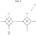
- FIG. 4 is a detailed view of an example of the scale unit 41 of FIG. 2 .
- the scale unit 41 may include a first multiplier 411 and a second multiplier 412.
- a linear modulation maximum value of the inverter 3 is V DC 3 . Accordingly, the first multiplier 411 may output V DC 3 . by multiplying an input DC link voltage by 1 3 .
- the second multiplier 412 may output by multiplying an output of the first multiplier 411 by a gain K for fine tuning.
- K may be a value set by a user considering margin due to voltage drop in an internal device of the inverter 3, and is a value less than 1.
- the fourth calculating unit 45 may receive an output of the scale unit 41 and a Q-axis voltage command, and deduct the Q-axis voltage command from the output of the scale unit 41. Since in V/F control, a D-axis voltage command is 0, the Q-axis voltage command is the same as an output voltage of the inverter 3.
- the PI controller 40 may receive an output of the fourth calculating unit 45 and output a control signal.
- the PI controller 40 may integrate the DC link voltage output from the fourth calculating unit 45 and an error signal of the Q-axis voltage command (that is, the output of the fourth calculating unit 45), and output a proportional-integral control value regarding the error.
- the fourth calculating unit 45 may output a value obtained by deducting the Q-axis voltage command (inverter output voltage) from a value of scaling the DC link voltage measured by the DC link voltage measurer 47 (output of the scale unit 41), and provide the value to the PI controller 40.
- the voltage determining unit 32 may determine an output voltage corresponding to an output frequency of the second calculating unit 430 ⁇
- the output voltage determined as above may be converted to a three-phase voltage by the first and second convertors 33 and 34 and applied to the motor 2.
- the output frequency applied to the voltage determining unit 32 is decreased by a negative control signal of the PI controller 40. Accordingly, as the output voltage decreases, the voltage applied to the motor 2 may be decreased by the V/f pattern as shown in FIG. 3 as well.
- the output voltage of the inverter 3 may be controlled within V DC 3 .
- FIG. 5 is a graph for explaining an operation of an inverter according to an embodiment of the present disclosure.
- a channel 1 5A indicates an input voltage of an inverter.
- a channel 2 5B indicates an output of the frequency generator 31.
- a channel 3 5C indicates an output of the second calculating unit 43.
- a channel 4 5D indicates an output Q-axis current of the inverter 3.
- the output frequency of the second calculating unit 43 is decreased by the output control signal of the PI controller 40 of the present disclosure (5C). Accordingly, it may be seen that the output frequency is less than the command frequency generated by the frequency generator 31.
- the Q-axis current command of the channel 4 may be seen from the Q-axis current command of the channel 4 that, when the input voltage of the inverter 3 decreases, the Q-axis current of the inverter 3 is increased due to overload of the motor 2. According to an embodiment of the present disclosure, the Q-axis current is maintained at a certain level.
- the output frequency is reduced without an increase in the Q-axis current due to lack of voltage at high speed, and thus the output frequency is controlled to fit to the input voltage of the inverter 3, thereby enabling a smooth operation.
- the output frequency is automatically controlled so that the hoist system 1 can lift an object.
- system stability may be secured and user convenience may be provided.
Landscapes
- Engineering & Computer Science (AREA)
- Power Engineering (AREA)
- Automation & Control Theory (AREA)
- Mechanical Engineering (AREA)
- Control Of Ac Motors In General (AREA)
- Inverter Devices (AREA)
Abstract
Description
- The present disclosure relates to an inverter.
- In general, a hoist signifies a mechanical apparatus having a function of lifting a heavy object by using a motor. An induction motor capable of directly inputting system power is often used for a hoist.
- When an induction motor mounted on a hoist apparatus is directly driven by using commercial power, a large inrush current is caused and the life of the induction motor is shortened. Also, since the induction motor is controlled at a single speed only, the inverter is generally used for driving the induction motor.
- An inverter is a sort of device that receive power supplied from a commercial power source and supplying the power to a motor by varying a voltage and a frequency thereof, thereby controlling a speed of a motor at high efficiency.
- When the inverter is used for a hoist apparatus, the induction motor may be driven at a desired speed by using a variable voltage variable frequency (VVVF) function of an inverter, and thus an inrush current may be prevented.
- When the inverter is mounted on the hoist apparatus to drive the induction motor at multi-level speed, the induction motor may be driven at a motor speed divided into a low speed and a high speed, or at a motor speed controlled by a user by using a two-step or three-step operation method.
- Since a counter-electromotive force increases as the speed of the induction motor increases, a higher driving voltage is needed. However, when the hoist apparatus is driven at high speed, an input voltage of the inverter is lowered due to a system malfunction, a voltage output from the inverter decreases as well. Accordingly, the induction motor may not be driven at a desired speed.
- Furthermore, when the input voltage of the inverter is lowered as a hoist holds an object, a trip of the inverter is generated and thus an accident may occur as the object being held falls.
- It is an object of the present disclosure to provide an inverter which may lift an object at a slightly lower speed than a desired speed, rather than falling an object or stopping an operation, even when an input voltage of the inverter in a hoist apparatus decreases, thereby improving user convenience and preventing accidents.
- Objects of the present disclosure are not limited to the above-described objects and other objects and advantages can be appreciated by those skilled in the art from the following descriptions. Further, it will be easily appreciated that the objects and advantages of the present disclosure can be practiced by means recited in the appended claims and a combination thereof.
- In accordance with one aspect of the present disclosure, an inverter provided in a hoist system includes a scale unit configured to control a size of a DC link voltage of the inverter, a proportional-integral (PI) controller configured to perform PI-control on an output of the scale unit and an output voltage of the inverter and outputting a control signal, a first calculating unit configured to sum a command frequency of the inverter and the control signal, and a voltage determining unit configured to determine an output voltage of the inverter from an output frequency of the first calculating unit.
- The scale unit may include a first multiplier configured to multiply the DC link voltage by

- The scale unit may further include a second multiplier configured to multiply an output of the first multiplier by a gain K that is less than 1 and output a resultant of the multiplication.
- The inverter may further include a first convertor configured to convert a Q-axis voltage of a synchronous reference frame that is an output of the voltage determining unit, to a Q-axis voltage of a stationary reference frame, and a second convertor configured to convert a Q-axis voltage of a stationary reference frame to a three-phase voltage.
- The inverter may further include a torque booster configured to determine a compensation voltage to compensate for a torque according to a size of an output current of the inverter, and a slip compensator configured to determine a compensation frequency to compensate a slip according to the size of the output current of the inverter the inverter.
- The inverter may further include a third convertor configured to convert the three-phase output current of the inverter to a Q-axis current of a stationary reference frame, and a fourth convertor configured to convert the Q-axis output current of the stationary reference frame to a Q-axis current of a synchronous reference frame.
- The inverter may further include a second calculating unit configured to sum the compensation voltage output from the torque booster and an output of the voltage determining unit.
- The inverter may further include a third calculating unit configured to sum the compensation frequency output from the slip compensator and a commend frequency of the inverter.
-
-
FIG. 1 is a schematic view of a hoist system adopting an inverter according to an embodiment of the present disclosure. -
FIG. 2 is a block diagram of a detailed configuration of an inverter according to an embodiment of the present disclosure. -
FIG. 3 is a graph for explaining that a voltage determining unit ofFIG. 2 determines a voltage corresponding to an input frequency. -
FIG. 4 is a detailed view of an example of a scale unit ofFIG. 2 . -
FIG. 5 is a graph for explaining an operation of an inverter according to an embodiment of the present disclosure. - The above objects, features and advantages will become apparent from the detailed description with reference to the accompanying drawings. Embodiments are described in sufficient detail to enable those skilled in the art in the art to easily practice the technical idea of the present disclosure. Detailed descriptions of well-known functions or configurations may be omitted in order not to unnecessarily obscure the gist of the present disclosure. Hereinafter, embodiments of the present disclosure will be described in detail with reference to the accompanying drawings. Throughout the drawings, like reference numerals refer to like elements.
- While such terms as "first," "second," etc., may be used to describe various components, such components must not be limited to the above terms. The above terms are used only to distinguish one component from another. For example, without deviating from the right scope of the present disclosure, a "first constituent element" may be referred to as a "'second constituent element", and similarly the "second constituent element" may be referred to as the "first constituent element". Furthermore, an expression used in a singular form in the present specification also includes the expression in its plural form unless clearly specified otherwise in context. Unless defined otherwise, all terms used herein including technical or scientific terms have the same meanings as those generally understood by those of ordinary skill in the art to which the present disclosure may pertain.
- In the following description, an inverter according to an embodiment of the present disclosure is described with reference to
FIGS. 1 to 5 . -
FIG. 1 is a schematic view of ahoist system 1 adopting aninverter 3 according to an embodiment of the present disclosure. - As illustrated in the drawing, in the
hoist system 1, awire rope 4 is released or wound by an operation of aninduction motor 2 for hoisting in acontrol box 6, and thus ahook 5 is moved up or down. Accordingly, an object held by thehook 5 is raised or lowered. - When the
induction motor 2 mounted in thehoist system 1 is directly driven by commercial power, a large inrush current is generated when the commercial power is applied thereto, and thus life of amotor 2 may be shortened and theinduction motor 2 may not be controlled at a single speed. Accordingly, thehoist system 1 is provided with theinverter 3, and thus the supply of power is performed by theinverter 3. When power is supplied to themotor 2 by theinverter 3, by a variable voltage variable frequency (VVVF) control method of theinverter 3, themotor 2 may be driven at a desired speed and an inrush current may be prevented. - When, in the
hoist system 1, themotor 2 is driven by theinverter 3 at multi-level speed, the induction motor may be driven at a motor speed divided into a low speed and a high speed, or at a motor speed controlled by a user by using a two-step or three-step operation method, which may be set by the user. To this end, thehoist system 1 may be further provided with a human-machine interface (HMI) connected to theinverter 3 through a network. - In general, since a counter-electromotive force increases as a speed increases, the
motor 2 needs a greater driving voltage. When a motor is driven at high speed and an input voltage of theinverter 3 deceases due to a system malfunction, a voltage to be output from theinverter 3 decreases as well, and thus themotor 2 may not be operated at a desired speed. Furthermore, since the same frequency is applied to themotor 2 even when the input voltage of theinverter 3 is lowered, overload is generated in themotor 2, and thus an object held by thehook 5 may fall or lifting up/down may be stopped. - Accordingly, the present disclosure provides a method of lifting an object up/down at a speed slightly lower than a desired speed without falling the object or stopping the lifting up/down even when the input voltage of the
inverter 3 decreases. Accordingly, the present disclosure may enhance user convenience and system stability. - In an embodiment of the present disclosure, the
motor 2 and theinverter 3 are briefly illustrated, the present disclosure is not limited to the arrangements and shapes of themotor 2 and theinverter 3, and may be variously configured according to the structure of thehoist system 1. -
FIG. 2 is a block diagram of a detailed configuration of aninverter 3 according to an embodiment of the present disclosure. - As illustrated in the drawing, the
inverter 3 according to the embodiment of the present disclosure may include afrequency generator 31, avoltage determining unit 32, first tofourth convertors 33 to 36, atorque booster 37, aslip compensator 38, a proportional-integral (PI)controller 40, ascale unit 41, first to fourth calculatingunits 42 to 45, and asensor 46. - The
frequency generator 31 may generate a command frequency that is a speed of themotor 2 set by a user. Thevoltage determining unit 32 may determine a voltage corresponding to an input frequency. -
FIG. 3 is a graph for explaining that thevoltage determining unit 32 ofFIG. 2 determines a voltage corresponding to an input frequency. - As illustrated in the drawing, the
voltage determining unit 32 according to the embodiment of the present disclosure may determine an output voltage corresponding to an input frequency by the VVVF control method. - In
FIG. 2 , thefirst convertor 33 may convert a Q-axis voltage VqseREF of a synchronous reference frame that is an output of the third calculatingunit 44, to a Q-axis voltage of a stationary reference frame, and thesecond convertor 34 may convert a Q-axis voltage of a stationary reference frame to a three-phase voltage. The three-phase voltage output from thesecond convertor 34 may be input to themotor 2 as an output of theinverter 3. - The
sensor 46, as a current transformer (CT) for example, may detect a current output from theinverter 3 to themotor 2. - The
third convertor 35 may convert the three-phase current output from theinverter 3 to themotor 2 and detected by thesensor 46, to a Q-axis current of a stationary reference frame, and thefourth convertor 36 may convert the Q-axis current of a stationary reference frame to a Q-axis current of a synchronous reference frame. - When the
first convertor 33 converts a Q-axis voltage of a synchronous reference frame to a stationary reference frame andfourth convertor 36 converts the Q-axis current of a stationary reference frame to a synchronous reference frame, thefirst convertor 33 and thefourth convertor 36 may perform coordinate system transformation by using a value (angle) obtained by integrating an input frequency that is an input of thevoltage determining unit 32, by anintegrator 39. An equation of transforming


- In this state, θ=∫ω edt and ω e may denote an input frequency applied to the
voltage determining unit 32. - The
torque booster 37 is provided to solve a problem occurring when a frequency is low and a low voltage is applied to magnetization inductance of themotor 2 due to a voltage drop by resistance of a stator of themotor 2, and thus a low current may flow in a rotor and a large torque may not be generated. Thetorque booster 37 may determine a compensation voltage according to the amount of a Q-axis current and provide a determined compensation voltage to the third calculatingunit 44. The torque may be increased according to the compensation voltage. - A compensation voltage Vboost determined by the
torque booster 37 may be determined according to the following equation.
- In the equation, Vrated denotes a rated voltage, Irated denotes a rated current, Frated denotes a rated frequency, Fsl,rated denotes a rated slip frequency, Iqs denotes a Q-axis current provided by the
fourth convertor 36. - The
slip compensator 38 may receive a Q-axis current from thefourth convertor 36 and determine a compensation frequency according to a size of a Q-axis current. In general, when a load is applied to themotor 2, the frequency of a rotor of themotor 2 rotor decreases, and a lowered frequency is referred to as a slip frequency. The size of a slip frequency is proportional to the size of a load, and the size of a load is approximately proportional to the amount of current. Accordingly, theslip compensator 38 may compensate for the frequency output from thefrequency generator 31 by determining the compensation frequency as inEquation 3.
- In the equation, Fcomp denotes a compensation frequency.
- The
scale unit 41 may receive a DC link voltage of theinverter 3 and convert the size of the DC link voltage to a maximum voltage that may be output from theinverter 3. Theinverter 3 receives commercial power 7, and arectifier 48 rectifies the commercial power 7 and stores a rectified voltage in a DC link capacitor (not shown). A DClink voltage measurer 47 according to an embodiment of the present disclosure may measure a DC link voltage stored in the DC link capacitor and provide the stored DC link voltage to thescale unit 41. -
FIG. 4 is a detailed view of an example of thescale unit 41 ofFIG. 2 . - As illustrated in the drawing, the
scale unit 41 according to the present embodiment of the present disclosure may include afirst multiplier 411 and asecond multiplier 412. - A linear modulation maximum value of the
inverter 3 is
first multiplier 411 mayoutput 

- The
second multiplier 412 may output by multiplying an output of thefirst multiplier 411 by a gain K for fine tuning. "K" may be a value set by a user considering margin due to voltage drop in an internal device of theinverter 3, and is a value less than 1. - The fourth calculating unit 45 may receive an output of the
scale unit 41 and a Q-axis voltage command, and deduct the Q-axis voltage command from the output of thescale unit 41. Since in V/F control, a D-axis voltage command is 0, the Q-axis voltage command is the same as an output voltage of theinverter 3. - The
PI controller 40 may receive an output of the fourth calculating unit 45 and output a control signal. In detail, thePI controller 40 may integrate the DC link voltage output from the fourth calculating unit 45 and an error signal of the Q-axis voltage command (that is, the output of the fourth calculating unit 45), and output a proportional-integral control value regarding the error. - The operation of the
inverter 3 according to an embodiment of the present disclosure is described below. - The fourth calculating unit 45 may output a value obtained by deducting the Q-axis voltage command (inverter output voltage) from a value of scaling the DC link voltage measured by the DC link voltage measurer 47 (output of the scale unit 41), and provide the value to the
PI controller 40. - In this state, when the input voltage of the
inverter 3 deceases due to an abnormal operation of the commercial power 7, the DC link voltage measured by the DClink voltage measurer 47 decreases. Accordingly, when the output of thescale unit 41 is less than the Q-axis voltage command that is the inverter output voltage, the output control signal of thePI controller 40 may be negative. - When a sum of the command frequency that is the output of the
frequency generator 31 and a compensation slip frequency that is the output of theslip compensator 38 is determined by the first calculatingunit 42, and the output control signal of thePI controller 40 and the output of the first calculatingunit 42 are summed by the second calculatingunit 43 and an output frequency is determined, thevoltage determining unit 32 may determine an output voltage corresponding to an output frequency of the second calculating unit 430┤|. The output voltage determined as above may be converted to a three-phase voltage by the first andsecond convertors motor 2. - In other words, the output frequency applied to the
voltage determining unit 32 is decreased by a negative control signal of thePI controller 40. Accordingly, as the output voltage decreases, the voltage applied to themotor 2 may be decreased by the V/f pattern as shown inFIG. 3 as well. - Accordingly, according to the present embodiment of the present disclosure, the output voltage of the
inverter 3 may be controlled within
-
FIG. 5 is a graph for explaining an operation of an inverter according to an embodiment of the present disclosure. Achannel 1 5A indicates an input voltage of an inverter. Achannel 2 5B indicates an output of thefrequency generator 31. Achannel 3 5C indicates an output of the second calculatingunit 43. Achannel 4 5D indicates an output Q-axis current of theinverter 3. - It may be seen from the
channel 1 that, even when the input voltage of theinverter 3 is decreased to a voltage of 187 V less than a rated voltage of 220V (5A), the output of thefrequency generator 31 is maintained constant (5B). - The output frequency of the second calculating
unit 43 is decreased by the output control signal of thePI controller 40 of the present disclosure (5C). Accordingly, it may be seen that the output frequency is less than the command frequency generated by thefrequency generator 31. - It may be seen from the Q-axis current command of the
channel 4 that, when the input voltage of theinverter 3 decreases, the Q-axis current of theinverter 3 is increased due to overload of themotor 2. According to an embodiment of the present disclosure, the Q-axis current is maintained at a certain level. - In other words, according to the
inverter 3 of the present disclosure, the output frequency is reduced without an increase in the Q-axis current due to lack of voltage at high speed, and thus the output frequency is controlled to fit to the input voltage of theinverter 3, thereby enabling a smooth operation. - As such, according to an embodiment of the present disclosure, even when the input voltage of the
inverter 3 is abnormally lowered, the output frequency is automatically controlled so that the hoistsystem 1 can lift an object. Thus, system stability may be secured and user convenience may be provided. - The present disclosure described above may be variously substituted, altered, and modified by those skilled in the art to which the present inventive concept pertains without departing from the scope and sprit of the present disclosure. Therefore, the present disclosure is not limited to the above-mentioned exemplary embodiments and the accompanying drawings.
Claims (10)
- An inverter provided in a hoist system (1), the inverter (3) comprising:a scale unit (41) configured to control a size of a DC link voltage of the inverter (3);a proportional-integral (PI) controller (40) configured to perform PI-control on an output of the scale unit (41) and an output voltage of the inverter (3) and outputting a control signal;a first calculating unit (42) configured to sum a command frequency of the inverter (3) and the control signal; anda voltage determining unit (32) configured to determine an output voltage of the inverter (3) from an output frequency of the first calculating unit (42).
- The inverter of claim 1, wherein the scale unit (41) comprises a first multiplier (411) configured to multiply the DC link voltage by

- The inverter of claim 2, wherein the scale unit (41) further comprises a second multiplier (412) configured to multiply an output of the first multiplier (411) by a gain K that is less than 1 and output a resultant of the multiplication.
- The inverter of claim 1, further comprising:a first convertor (33) configured to convert a Q-axis voltage of a synchronous reference frame that is an output of the voltage determining unit (32), to a Q-axis voltage of a stationary reference frame; anda second convertor (34) configured to convert a Q-axis voltage of a stationary reference frame to a three-phase voltage.
- The inverter of claim 1, further comprising:a torque booster (37) configured to determine a compensation voltage to compensate for a torque according to a size of an output current of the inverter (3); anda slip compensator (38) configured to determine a compensation frequency to compensate a slip according to the size of the output current of the inverter (3).
- The inverter of claim 5, wherein the compensation voltage and the compensation frequency are proportional to the size of the output current.
- The inverter of claim 5, further comprising:a third convertor (35) configured to convert the three-phase output current of the inverter (3) to a Q-axis current of a stationary reference frame; anda fourth convertor (36) configured to convert the Q-axis output current of the stationary reference frame to a Q-axis current of a synchronous reference frame.
- The inverter of claim 5, further comprising a second calculating unit (43) configured to sum the compensation voltage output from the torque booster (37) and an output of the voltage determining unit (32).
- The inverter of claim 5, further comprising a third calculating unit (44) configured to sum the compensation frequency output from the slip compensator (38) and a commend frequency of the inverter (3).
- The inverter of claim 1, further comprising:a rectifier (48) configured to receive and rectify a commercial power; anda voltage measurer (47) configured to measure the DC link voltage rectified by the rectifier (48) and stored in a DC link capacitor.
Applications Claiming Priority (1)
| Application Number | Priority Date | Filing Date | Title |
|---|---|---|---|
| KR1020180012683A KR102019827B1 (en) | 2018-02-01 | 2018-02-01 | Inverter |
Publications (2)
| Publication Number | Publication Date |
|---|---|
| EP3522364A1 true EP3522364A1 (en) | 2019-08-07 |
| EP3522364B1 EP3522364B1 (en) | 2021-09-29 |
Family
ID=61971954
Family Applications (1)
| Application Number | Title | Priority Date | Filing Date |
|---|---|---|---|
| EP18166805.4A Not-in-force EP3522364B1 (en) | 2018-02-01 | 2018-04-11 | Inverter |
Country Status (6)
| Country | Link |
|---|---|
| US (1) | US10277143B1 (en) |
| EP (1) | EP3522364B1 (en) |
| JP (1) | JP6595034B2 (en) |
| KR (1) | KR102019827B1 (en) |
| CN (1) | CN110112941B (en) |
| ES (1) | ES2900245T3 (en) |
Families Citing this family (5)
| Publication number | Priority date | Publication date | Assignee | Title |
|---|---|---|---|---|
| CN112398413B (en) * | 2019-08-12 | 2022-07-12 | 乐星电气(无锡)有限公司 | Frequency converter torque lifting system and method and frequency converter |
| CN110635704B (en) * | 2019-08-22 | 2021-08-24 | 江苏固德威电源科技股份有限公司 | Inverter bus voltage control method |
| CN115010000B (en) * | 2022-07-01 | 2023-09-01 | 同济大学 | Intelligent driving method based on traditional travelling crane |
| US20250096714A1 (en) * | 2023-09-19 | 2025-03-20 | Steering Solutions Ip Holding Corporation | Feedback current control of induction machines |
| CN119637732B (en) * | 2025-02-19 | 2025-04-18 | 湖南省汇川电子科技有限公司 | Remote control system of frequency converter |
Citations (4)
| Publication number | Priority date | Publication date | Assignee | Title |
|---|---|---|---|---|
| WO2003044939A1 (en) * | 2001-11-23 | 2003-05-30 | Danfoss Drives A/S | Frequency converter for different mains voltages |
| CN102291085B (en) * | 2011-08-23 | 2013-05-22 | 东北电网有限公司 | Asynchronous motor frequency converter device with low-voltage ride through capability |
| US20130154536A1 (en) * | 2011-12-14 | 2013-06-20 | Lsis Co., Ltd | Apparatus for controlling an inverter |
| EP3193444A1 (en) * | 2016-01-18 | 2017-07-19 | LSIS Co., Ltd. | Inverter |
Family Cites Families (17)
| Publication number | Priority date | Publication date | Assignee | Title |
|---|---|---|---|---|
| JPH03155392A (en) * | 1989-11-10 | 1991-07-03 | Toshiba Corp | Current detecting unit |
| JPH09131094A (en) * | 1995-10-30 | 1997-05-16 | Daikin Ind Ltd | Motor control device for air conditioner and motor control method |
| KR100421373B1 (en) * | 2001-06-20 | 2004-03-06 | 엘지전자 주식회사 | Apparatus for rotary velocity control of synchronous reluctance motor |
| KR100442494B1 (en) * | 2002-02-26 | 2004-07-30 | 엘지산전 주식회사 | Control method and controller for torque of inverter |
| JP2005027410A (en) | 2003-07-01 | 2005-01-27 | Tsudakoma Corp | Induction motor driving method and driving apparatus |
| JP4910467B2 (en) * | 2006-04-21 | 2012-04-04 | 株式会社明電舎 | Variable speed control device for motor |
| WO2008121868A1 (en) * | 2007-03-30 | 2008-10-09 | Acciona Windpower S.A. | Dc voltage regulator |
| US7511459B2 (en) * | 2007-06-11 | 2009-03-31 | Sunpower, Inc. | Controller computing a virtual tuning capacitor for controlling a free-piston stirling engine driving a linear alternator |
| KR100951511B1 (en) * | 2008-03-10 | 2010-04-07 | 엘에스산전 주식회사 | Induction motor controller |
| KR101210022B1 (en) | 2010-12-30 | 2012-12-07 | 엘에스산전 주식회사 | Method for continuously driving an inverter for driving an induction motor |
| US8981743B2 (en) * | 2011-09-05 | 2015-03-17 | Stmicroelectronics S.R.L. | Constant-on-time multi-phase switching voltage regulator and related method of generating a regulated voltage |
| US9847735B2 (en) * | 2012-04-20 | 2017-12-19 | Mitsubishi Electric Corporation | Power conversion device, motor drive control apparatus including the power conversion device, air blower and compressor including the motor drive control apparatus, and air conditioner including the air blower or the compressor |
| US8994320B2 (en) * | 2013-06-28 | 2015-03-31 | Eaton Corporation | System and method for controlling regenerating energy in an adjustable speed drive |
| CN107836077B (en) * | 2015-07-09 | 2020-07-07 | 三菱电机株式会社 | Motor control device |
| US9871462B2 (en) * | 2015-12-11 | 2018-01-16 | Phase Technologies, Llc | Regenerative variable frequency drive with auxiliary power supply |
| KR102546709B1 (en) * | 2016-04-26 | 2023-06-21 | 엘에스일렉트릭(주) | Voltage compensation method for motor control inverter |
| KR101906011B1 (en) * | 2016-12-13 | 2018-10-10 | 현대자동차주식회사 | Method for estimating power consumption of motor in fuel cell system |
-
2018
- 2018-02-01 KR KR1020180012683A patent/KR102019827B1/en not_active Expired - Fee Related
- 2018-04-11 ES ES18166805T patent/ES2900245T3/en active Active
- 2018-04-11 EP EP18166805.4A patent/EP3522364B1/en not_active Not-in-force
- 2018-04-20 JP JP2018081548A patent/JP6595034B2/en not_active Expired - Fee Related
- 2018-04-20 US US15/958,201 patent/US10277143B1/en active Active
- 2018-04-25 CN CN201810377637.0A patent/CN110112941B/en not_active Expired - Fee Related
Patent Citations (4)
| Publication number | Priority date | Publication date | Assignee | Title |
|---|---|---|---|---|
| WO2003044939A1 (en) * | 2001-11-23 | 2003-05-30 | Danfoss Drives A/S | Frequency converter for different mains voltages |
| CN102291085B (en) * | 2011-08-23 | 2013-05-22 | 东北电网有限公司 | Asynchronous motor frequency converter device with low-voltage ride through capability |
| US20130154536A1 (en) * | 2011-12-14 | 2013-06-20 | Lsis Co., Ltd | Apparatus for controlling an inverter |
| EP3193444A1 (en) * | 2016-01-18 | 2017-07-19 | LSIS Co., Ltd. | Inverter |
Also Published As
| Publication number | Publication date |
|---|---|
| JP2019134657A (en) | 2019-08-08 |
| CN110112941A (en) | 2019-08-09 |
| KR102019827B1 (en) | 2019-09-09 |
| CN110112941B (en) | 2021-02-26 |
| EP3522364B1 (en) | 2021-09-29 |
| JP6595034B2 (en) | 2019-10-23 |
| ES2900245T3 (en) | 2022-03-16 |
| KR20190093270A (en) | 2019-08-09 |
| US10277143B1 (en) | 2019-04-30 |
Similar Documents
| Publication | Publication Date | Title |
|---|---|---|
| EP3522364B1 (en) | Inverter | |
| KR100396801B1 (en) | Elevator control apparatus | |
| JP3251628B2 (en) | Elevator speed control device | |
| US7468595B2 (en) | System and method of controlling the start-up of an adjustable speed motor drive based sinusoidal output power conditioner | |
| US9160262B2 (en) | Sensorless motor control | |
| EP3014761B1 (en) | System and method for controlling regenerating energy in an adjustable speed drive | |
| JP4461877B2 (en) | Inverter device | |
| RU2539557C2 (en) | Limitation of overload current at regulation of inverter-powered three-phase motors | |
| EP2931639B1 (en) | Elevator speed control | |
| CN106301130A (en) | The control method of a kind of automatic load shedding of motor-driven dynamic overload and system | |
| US4851982A (en) | Apparatus for controlling an A.C. powered elevator | |
| EP1657808A2 (en) | Frequency converter overvoltage protection | |
| US7449860B2 (en) | Control technique for limiting the current of an induction machine drive system | |
| JP3773794B2 (en) | Power converter | |
| US20130271061A1 (en) | Method for controlling an asynchronous machine having a converter in a manner that is optimal for (copper) loss | |
| EP1788911B1 (en) | Operating a three phase device using single phase power | |
| EP3068036B1 (en) | Inverter for supplying load-adaptive boost voltage | |
| JPH10164883A (en) | Inverter control device | |
| JP4174632B2 (en) | Light load speed increaser for inverter controlled crane / hoist | |
| KR102036031B1 (en) | Apparatus for controlling inverter | |
| KR100817474B1 (en) | Hoist Control Unit | |
| EP3139489B1 (en) | Method for braking an alternating current electric motor | |
| JPH06189411A (en) | Blackout detection method for AC electric vehicles | |
| CN1047893C (en) | Apparatus for regulating an elevator motor | |
| JP2633950B2 (en) | Power converter |
Legal Events
| Date | Code | Title | Description |
|---|---|---|---|
| PUAI | Public reference made under article 153(3) epc to a published international application that has entered the european phase |
Free format text: ORIGINAL CODE: 0009012 |
|
| STAA | Information on the status of an ep patent application or granted ep patent |
Free format text: STATUS: REQUEST FOR EXAMINATION WAS MADE |
|
| 17P | Request for examination filed |
Effective date: 20190626 |
|
| AK | Designated contracting states |
Kind code of ref document: A1 Designated state(s): AL AT BE BG CH CY CZ DE DK EE ES FI FR GB GR HR HU IE IS IT LI LT LU LV MC MK MT NL NO PL PT RO RS SE SI SK SM TR |
|
| AX | Request for extension of the european patent |
Extension state: BA ME |
|
| STAA | Information on the status of an ep patent application or granted ep patent |
Free format text: STATUS: EXAMINATION IS IN PROGRESS |
|
| 17Q | First examination report despatched |
Effective date: 20190906 |
|
| GRAP | Despatch of communication of intention to grant a patent |
Free format text: ORIGINAL CODE: EPIDOSNIGR1 |
|
| STAA | Information on the status of an ep patent application or granted ep patent |
Free format text: STATUS: GRANT OF PATENT IS INTENDED |
|
| INTG | Intention to grant announced |
Effective date: 20210624 |
|
| GRAS | Grant fee paid |
Free format text: ORIGINAL CODE: EPIDOSNIGR3 |
|
| GRAA | (expected) grant |
Free format text: ORIGINAL CODE: 0009210 |
|
| STAA | Information on the status of an ep patent application or granted ep patent |
Free format text: STATUS: THE PATENT HAS BEEN GRANTED |
|
| AK | Designated contracting states |
Kind code of ref document: B1 Designated state(s): AL AT BE BG CH CY CZ DE DK EE ES FI FR GB GR HR HU IE IS IT LI LT LU LV MC MK MT NL NO PL PT RO RS SE SI SK SM TR |
|
| REG | Reference to a national code |
Ref country code: GB Ref legal event code: FG4D |
|
| REG | Reference to a national code |
Ref country code: CH Ref legal event code: EP Ref country code: AT Ref legal event code: REF Ref document number: 1435103 Country of ref document: AT Kind code of ref document: T Effective date: 20211015 |
|
| REG | Reference to a national code |
Ref country code: DE Ref legal event code: R096 Ref document number: 602018024128 Country of ref document: DE |
|
| REG | Reference to a national code |
Ref country code: IE Ref legal event code: FG4D |
|
| REG | Reference to a national code |
Ref country code: LT Ref legal event code: MG9D |
|
| PG25 | Lapsed in a contracting state [announced via postgrant information from national office to epo] |
Ref country code: RS Free format text: LAPSE BECAUSE OF FAILURE TO SUBMIT A TRANSLATION OF THE DESCRIPTION OR TO PAY THE FEE WITHIN THE PRESCRIBED TIME-LIMIT Effective date: 20210929 Ref country code: SE Free format text: LAPSE BECAUSE OF FAILURE TO SUBMIT A TRANSLATION OF THE DESCRIPTION OR TO PAY THE FEE WITHIN THE PRESCRIBED TIME-LIMIT Effective date: 20210929 Ref country code: HR Free format text: LAPSE BECAUSE OF FAILURE TO SUBMIT A TRANSLATION OF THE DESCRIPTION OR TO PAY THE FEE WITHIN THE PRESCRIBED TIME-LIMIT Effective date: 20210929 Ref country code: FI Free format text: LAPSE BECAUSE OF FAILURE TO SUBMIT A TRANSLATION OF THE DESCRIPTION OR TO PAY THE FEE WITHIN THE PRESCRIBED TIME-LIMIT Effective date: 20210929 Ref country code: NO Free format text: LAPSE BECAUSE OF FAILURE TO SUBMIT A TRANSLATION OF THE DESCRIPTION OR TO PAY THE FEE WITHIN THE PRESCRIBED TIME-LIMIT Effective date: 20211229 Ref country code: LT Free format text: LAPSE BECAUSE OF FAILURE TO SUBMIT A TRANSLATION OF THE DESCRIPTION OR TO PAY THE FEE WITHIN THE PRESCRIBED TIME-LIMIT Effective date: 20210929 Ref country code: BG Free format text: LAPSE BECAUSE OF FAILURE TO SUBMIT A TRANSLATION OF THE DESCRIPTION OR TO PAY THE FEE WITHIN THE PRESCRIBED TIME-LIMIT Effective date: 20211229 |
|
| REG | Reference to a national code |
Ref country code: NL Ref legal event code: MP Effective date: 20210929 |
|
| REG | Reference to a national code |
Ref country code: AT Ref legal event code: MK05 Ref document number: 1435103 Country of ref document: AT Kind code of ref document: T Effective date: 20210929 |
|
| PG25 | Lapsed in a contracting state [announced via postgrant information from national office to epo] |
Ref country code: LV Free format text: LAPSE BECAUSE OF FAILURE TO SUBMIT A TRANSLATION OF THE DESCRIPTION OR TO PAY THE FEE WITHIN THE PRESCRIBED TIME-LIMIT Effective date: 20210929 Ref country code: GR Free format text: LAPSE BECAUSE OF FAILURE TO SUBMIT A TRANSLATION OF THE DESCRIPTION OR TO PAY THE FEE WITHIN THE PRESCRIBED TIME-LIMIT Effective date: 20211230 |
|
| REG | Reference to a national code |
Ref country code: ES Ref legal event code: FG2A Ref document number: 2900245 Country of ref document: ES Kind code of ref document: T3 Effective date: 20220316 |
|
| PG25 | Lapsed in a contracting state [announced via postgrant information from national office to epo] |
Ref country code: AT Free format text: LAPSE BECAUSE OF FAILURE TO SUBMIT A TRANSLATION OF THE DESCRIPTION OR TO PAY THE FEE WITHIN THE PRESCRIBED TIME-LIMIT Effective date: 20210929 |
|
| PGFP | Annual fee paid to national office [announced via postgrant information from national office to epo] |
Ref country code: GB Payment date: 20220307 Year of fee payment: 5 |
|
| PG25 | Lapsed in a contracting state [announced via postgrant information from national office to epo] |
Ref country code: IS Free format text: LAPSE BECAUSE OF FAILURE TO SUBMIT A TRANSLATION OF THE DESCRIPTION OR TO PAY THE FEE WITHIN THE PRESCRIBED TIME-LIMIT Effective date: 20220129 Ref country code: SK Free format text: LAPSE BECAUSE OF FAILURE TO SUBMIT A TRANSLATION OF THE DESCRIPTION OR TO PAY THE FEE WITHIN THE PRESCRIBED TIME-LIMIT Effective date: 20210929 Ref country code: RO Free format text: LAPSE BECAUSE OF FAILURE TO SUBMIT A TRANSLATION OF THE DESCRIPTION OR TO PAY THE FEE WITHIN THE PRESCRIBED TIME-LIMIT Effective date: 20210929 Ref country code: PT Free format text: LAPSE BECAUSE OF FAILURE TO SUBMIT A TRANSLATION OF THE DESCRIPTION OR TO PAY THE FEE WITHIN THE PRESCRIBED TIME-LIMIT Effective date: 20220131 Ref country code: PL Free format text: LAPSE BECAUSE OF FAILURE TO SUBMIT A TRANSLATION OF THE DESCRIPTION OR TO PAY THE FEE WITHIN THE PRESCRIBED TIME-LIMIT Effective date: 20210929 Ref country code: NL Free format text: LAPSE BECAUSE OF FAILURE TO SUBMIT A TRANSLATION OF THE DESCRIPTION OR TO PAY THE FEE WITHIN THE PRESCRIBED TIME-LIMIT Effective date: 20210929 Ref country code: EE Free format text: LAPSE BECAUSE OF FAILURE TO SUBMIT A TRANSLATION OF THE DESCRIPTION OR TO PAY THE FEE WITHIN THE PRESCRIBED TIME-LIMIT Effective date: 20210929 Ref country code: CZ Free format text: LAPSE BECAUSE OF FAILURE TO SUBMIT A TRANSLATION OF THE DESCRIPTION OR TO PAY THE FEE WITHIN THE PRESCRIBED TIME-LIMIT Effective date: 20210929 Ref country code: AL Free format text: LAPSE BECAUSE OF FAILURE TO SUBMIT A TRANSLATION OF THE DESCRIPTION OR TO PAY THE FEE WITHIN THE PRESCRIBED TIME-LIMIT Effective date: 20210929 |
|
| PGFP | Annual fee paid to national office [announced via postgrant information from national office to epo] |
Ref country code: IT Payment date: 20220309 Year of fee payment: 5 |
|
| REG | Reference to a national code |
Ref country code: DE Ref legal event code: R097 Ref document number: 602018024128 Country of ref document: DE |
|
| PG25 | Lapsed in a contracting state [announced via postgrant information from national office to epo] |
Ref country code: DK Free format text: LAPSE BECAUSE OF FAILURE TO SUBMIT A TRANSLATION OF THE DESCRIPTION OR TO PAY THE FEE WITHIN THE PRESCRIBED TIME-LIMIT Effective date: 20210929 |
|
| PGFP | Annual fee paid to national office [announced via postgrant information from national office to epo] |
Ref country code: ES Payment date: 20220509 Year of fee payment: 5 Ref country code: DE Payment date: 20220308 Year of fee payment: 5 |
|
| PLBE | No opposition filed within time limit |
Free format text: ORIGINAL CODE: 0009261 |
|
| STAA | Information on the status of an ep patent application or granted ep patent |
Free format text: STATUS: NO OPPOSITION FILED WITHIN TIME LIMIT |
|
| 26N | No opposition filed |
Effective date: 20220630 |
|
| PG25 | Lapsed in a contracting state [announced via postgrant information from national office to epo] |
Ref country code: SI Free format text: LAPSE BECAUSE OF FAILURE TO SUBMIT A TRANSLATION OF THE DESCRIPTION OR TO PAY THE FEE WITHIN THE PRESCRIBED TIME-LIMIT Effective date: 20210929 |
|
| REG | Reference to a national code |
Ref country code: CH Ref legal event code: PL |
|
| REG | Reference to a national code |
Ref country code: BE Ref legal event code: MM Effective date: 20220430 |
|
| PG25 | Lapsed in a contracting state [announced via postgrant information from national office to epo] |
Ref country code: MC Free format text: LAPSE BECAUSE OF FAILURE TO SUBMIT A TRANSLATION OF THE DESCRIPTION OR TO PAY THE FEE WITHIN THE PRESCRIBED TIME-LIMIT Effective date: 20210929 Ref country code: LU Free format text: LAPSE BECAUSE OF NON-PAYMENT OF DUE FEES Effective date: 20220411 Ref country code: LI Free format text: LAPSE BECAUSE OF NON-PAYMENT OF DUE FEES Effective date: 20220430 Ref country code: FR Free format text: LAPSE BECAUSE OF NON-PAYMENT OF DUE FEES Effective date: 20220430 Ref country code: CH Free format text: LAPSE BECAUSE OF NON-PAYMENT OF DUE FEES Effective date: 20220430 |
|
| PG25 | Lapsed in a contracting state [announced via postgrant information from national office to epo] |
Ref country code: BE Free format text: LAPSE BECAUSE OF NON-PAYMENT OF DUE FEES Effective date: 20220430 |
|
| PG25 | Lapsed in a contracting state [announced via postgrant information from national office to epo] |
Ref country code: IE Free format text: LAPSE BECAUSE OF NON-PAYMENT OF DUE FEES Effective date: 20220411 |
|
| REG | Reference to a national code |
Ref country code: DE Ref legal event code: R119 Ref document number: 602018024128 Country of ref document: DE |
|
| GBPC | Gb: european patent ceased through non-payment of renewal fee |
Effective date: 20230411 |
|
| PG25 | Lapsed in a contracting state [announced via postgrant information from national office to epo] |
Ref country code: GB Free format text: LAPSE BECAUSE OF NON-PAYMENT OF DUE FEES Effective date: 20230411 |
|
| PG25 | Lapsed in a contracting state [announced via postgrant information from national office to epo] |
Ref country code: GB Free format text: LAPSE BECAUSE OF NON-PAYMENT OF DUE FEES Effective date: 20230411 Ref country code: DE Free format text: LAPSE BECAUSE OF NON-PAYMENT OF DUE FEES Effective date: 20231103 |
|
| PG25 | Lapsed in a contracting state [announced via postgrant information from national office to epo] |
Ref country code: HU Free format text: LAPSE BECAUSE OF FAILURE TO SUBMIT A TRANSLATION OF THE DESCRIPTION OR TO PAY THE FEE WITHIN THE PRESCRIBED TIME-LIMIT; INVALID AB INITIO Effective date: 20180411 |
|
| PG25 | Lapsed in a contracting state [announced via postgrant information from national office to epo] |
Ref country code: SM Free format text: LAPSE BECAUSE OF FAILURE TO SUBMIT A TRANSLATION OF THE DESCRIPTION OR TO PAY THE FEE WITHIN THE PRESCRIBED TIME-LIMIT Effective date: 20210929 Ref country code: MK Free format text: LAPSE BECAUSE OF FAILURE TO SUBMIT A TRANSLATION OF THE DESCRIPTION OR TO PAY THE FEE WITHIN THE PRESCRIBED TIME-LIMIT Effective date: 20210929 Ref country code: IT Free format text: LAPSE BECAUSE OF NON-PAYMENT OF DUE FEES Effective date: 20230411 Ref country code: CY Free format text: LAPSE BECAUSE OF FAILURE TO SUBMIT A TRANSLATION OF THE DESCRIPTION OR TO PAY THE FEE WITHIN THE PRESCRIBED TIME-LIMIT Effective date: 20210929 |
|
| REG | Reference to a national code |
Ref country code: ES Ref legal event code: FD2A Effective date: 20240527 |
|
| PG25 | Lapsed in a contracting state [announced via postgrant information from national office to epo] |
Ref country code: ES Free format text: LAPSE BECAUSE OF NON-PAYMENT OF DUE FEES Effective date: 20230412 |
|
| PG25 | Lapsed in a contracting state [announced via postgrant information from national office to epo] |
Ref country code: ES Free format text: LAPSE BECAUSE OF NON-PAYMENT OF DUE FEES Effective date: 20230412 |
|
| PG25 | Lapsed in a contracting state [announced via postgrant information from national office to epo] |
Ref country code: MT Free format text: LAPSE BECAUSE OF FAILURE TO SUBMIT A TRANSLATION OF THE DESCRIPTION OR TO PAY THE FEE WITHIN THE PRESCRIBED TIME-LIMIT Effective date: 20210929 |
|
| PG25 | Lapsed in a contracting state [announced via postgrant information from national office to epo] |
Ref country code: TR Free format text: LAPSE BECAUSE OF FAILURE TO SUBMIT A TRANSLATION OF THE DESCRIPTION OR TO PAY THE FEE WITHIN THE PRESCRIBED TIME-LIMIT Effective date: 20210929 |