EP3522304B1 - Terminal block - Google Patents
Terminal block Download PDFInfo
- Publication number
- EP3522304B1 EP3522304B1 EP17856113.0A EP17856113A EP3522304B1 EP 3522304 B1 EP3522304 B1 EP 3522304B1 EP 17856113 A EP17856113 A EP 17856113A EP 3522304 B1 EP3522304 B1 EP 3522304B1
- Authority
- EP
- European Patent Office
- Prior art keywords
- plate spring
- wiring member
- side wall
- terminal
- wall portion
- Prior art date
- Legal status (The legal status is an assumption and is not a legal conclusion. Google has not performed a legal analysis and makes no representation as to the accuracy of the status listed.)
- Active
Links
- 230000004308 accommodation Effects 0.000 claims description 62
- 230000005489 elastic deformation Effects 0.000 claims description 3
- 238000005192 partition Methods 0.000 description 10
- 230000000630 rising effect Effects 0.000 description 8
- 230000004048 modification Effects 0.000 description 5
- 238000012986 modification Methods 0.000 description 5
- 230000000694 effects Effects 0.000 description 4
- 230000000052 comparative effect Effects 0.000 description 3
- 239000004020 conductor Substances 0.000 description 3
- 241000755266 Kathetostoma giganteum Species 0.000 description 2
- 239000000470 constituent Substances 0.000 description 1
- 238000010276 construction Methods 0.000 description 1
- 230000001747 exhibiting effect Effects 0.000 description 1
- 238000003780 insertion Methods 0.000 description 1
- 230000037431 insertion Effects 0.000 description 1
- 230000000717 retained effect Effects 0.000 description 1
Images


Classifications
-
- H—ELECTRICITY
- H01—ELECTRIC ELEMENTS
- H01R—ELECTRICALLY-CONDUCTIVE CONNECTIONS; STRUCTURAL ASSOCIATIONS OF A PLURALITY OF MUTUALLY-INSULATED ELECTRICAL CONNECTING ELEMENTS; COUPLING DEVICES; CURRENT COLLECTORS
- H01R9/00—Structural associations of a plurality of mutually-insulated electrical connecting elements, e.g. terminal strips or terminal blocks; Terminals or binding posts mounted upon a base or in a case; Bases therefor
- H01R9/22—Bases, e.g. strip, block, panel
- H01R9/24—Terminal blocks
-
- H—ELECTRICITY
- H01—ELECTRIC ELEMENTS
- H01R—ELECTRICALLY-CONDUCTIVE CONNECTIONS; STRUCTURAL ASSOCIATIONS OF A PLURALITY OF MUTUALLY-INSULATED ELECTRICAL CONNECTING ELEMENTS; COUPLING DEVICES; CURRENT COLLECTORS
- H01R9/00—Structural associations of a plurality of mutually-insulated electrical connecting elements, e.g. terminal strips or terminal blocks; Terminals or binding posts mounted upon a base or in a case; Bases therefor
- H01R9/22—Bases, e.g. strip, block, panel
- H01R9/24—Terminal blocks
- H01R9/2408—Modular blocks
-
- H—ELECTRICITY
- H01—ELECTRIC ELEMENTS
- H01R—ELECTRICALLY-CONDUCTIVE CONNECTIONS; STRUCTURAL ASSOCIATIONS OF A PLURALITY OF MUTUALLY-INSULATED ELECTRICAL CONNECTING ELEMENTS; COUPLING DEVICES; CURRENT COLLECTORS
- H01R4/00—Electrically-conductive connections between two or more conductive members in direct contact, i.e. touching one another; Means for effecting or maintaining such contact; Electrically-conductive connections having two or more spaced connecting locations for conductors and using contact members penetrating insulation
- H01R4/28—Clamped connections, spring connections
- H01R4/48—Clamped connections, spring connections utilising a spring, clip, or other resilient member
-
- H—ELECTRICITY
- H01—ELECTRIC ELEMENTS
- H01R—ELECTRICALLY-CONDUCTIVE CONNECTIONS; STRUCTURAL ASSOCIATIONS OF A PLURALITY OF MUTUALLY-INSULATED ELECTRICAL CONNECTING ELEMENTS; COUPLING DEVICES; CURRENT COLLECTORS
- H01R4/00—Electrically-conductive connections between two or more conductive members in direct contact, i.e. touching one another; Means for effecting or maintaining such contact; Electrically-conductive connections having two or more spaced connecting locations for conductors and using contact members penetrating insulation
- H01R4/28—Clamped connections, spring connections
- H01R4/48—Clamped connections, spring connections utilising a spring, clip, or other resilient member
- H01R4/4809—Clamped connections, spring connections utilising a spring, clip, or other resilient member using a leaf spring to bias the conductor toward the busbar
- H01R4/48185—Clamped connections, spring connections utilising a spring, clip, or other resilient member using a leaf spring to bias the conductor toward the busbar adapted for axial insertion of a wire end
- H01R4/4819—Clamped connections, spring connections utilising a spring, clip, or other resilient member using a leaf spring to bias the conductor toward the busbar adapted for axial insertion of a wire end the spring shape allowing insertion of the conductor end when the spring is unbiased
- H01R4/4821—Single-blade spring
-
- H—ELECTRICITY
- H01—ELECTRIC ELEMENTS
- H01R—ELECTRICALLY-CONDUCTIVE CONNECTIONS; STRUCTURAL ASSOCIATIONS OF A PLURALITY OF MUTUALLY-INSULATED ELECTRICAL CONNECTING ELEMENTS; COUPLING DEVICES; CURRENT COLLECTORS
- H01R4/00—Electrically-conductive connections between two or more conductive members in direct contact, i.e. touching one another; Means for effecting or maintaining such contact; Electrically-conductive connections having two or more spaced connecting locations for conductors and using contact members penetrating insulation
- H01R4/28—Clamped connections, spring connections
- H01R4/48—Clamped connections, spring connections utilising a spring, clip, or other resilient member
- H01R4/4809—Clamped connections, spring connections utilising a spring, clip, or other resilient member using a leaf spring to bias the conductor toward the busbar
- H01R4/484—Spring housing details
- H01R4/4842—Spring housing details the spring housing being provided with a single opening for insertion of a spring-activating tool
-
- H—ELECTRICITY
- H01—ELECTRIC ELEMENTS
- H01R—ELECTRICALLY-CONDUCTIVE CONNECTIONS; STRUCTURAL ASSOCIATIONS OF A PLURALITY OF MUTUALLY-INSULATED ELECTRICAL CONNECTING ELEMENTS; COUPLING DEVICES; CURRENT COLLECTORS
- H01R4/00—Electrically-conductive connections between two or more conductive members in direct contact, i.e. touching one another; Means for effecting or maintaining such contact; Electrically-conductive connections having two or more spaced connecting locations for conductors and using contact members penetrating insulation
- H01R4/28—Clamped connections, spring connections
- H01R4/48—Clamped connections, spring connections utilising a spring, clip, or other resilient member
- H01R4/4809—Clamped connections, spring connections utilising a spring, clip, or other resilient member using a leaf spring to bias the conductor toward the busbar
- H01R4/4846—Busbar details
Definitions
- US 2013/0237095 A1 discloses an electrical connector that includes a housing having outwardly extending sleeves for connection with a corresponding connector.
- the housing defines an aperture extending through the extending sleeves, and an electrically-conductive contact is retained within the interior space of the housing and extending into the aperture.
- the electrically-conductive contact has an end comprising a contact portion within the aperture and an opposite end comprising a push-in type contact element.
- a cap retains the contact within the interior space, enclosing the interior space, and defining a port to allow insertion of a conductor of various construction therethrough.
- the contact portion defines a wire receiving compartment.
- the push-in type contact element is pushed into the wire receiving compartment.
- the wire receiving compartment with the push-in type contact arranged therein is configured to receive the inserted conductor and to constrain the inserted conductor to a confined area so as to avoid spreading of a stranded wire and the like.
- the wiring member is hardly fixed in a direction that intersects with (for example, a direction that is orthogonal to) the directions in which the plate spring and the terminal portion hold the wiring member.
- a twisting force repeatedly acts on the wiring member, the wiring member repeatedly moves back and forth in the intersecting direction, and as a result, there is a possibility that the wiring member will come off from a position between the plate spring and the terminal portion.
- a movement of a portion of a wiring member that is inserted into an accommodation portion is curbed by a first side wall portion and a second side wall portion that are formed in the accommodation portion, and thus it is possible to further reduce the possibility that the wiring member held between a plate spring portion and a terminal portion will come off from a position between the plate spring portion and the terminal portion, compared to a conventional configuration.
- the terminal blocks 20A and 20B have approximately the same configuration, and thus only the terminal block 20A will be described below and a description of the terminal block 20B is not repeated. Specifically, a configuration of the terminal block 20A in this embodiment will be described with reference to Figs. 2 to 6 . Effects of the terminal block 20A will be described later with reference to Figs. 7 and 8 .
- the upper surface portion 40C, the bottom portion 40D, and the middle portion 40E of the front panel 40 each have a plate shape (see Fig. 5 ), and the upper surface portion 40C, the bottom portion 40D, and the middle portion 40E are disposed in parallel to each other.
- the upper surface portion 40C extends from an upper end of the front portion 40A toward the back, and the bottom portion 40D extends from a lower end of the front portion 40A toward the back.
- the middle portion 40E extends from a middle position of the front portion 40A toward the back.
- a plurality of partition walls 45 are provided on the back side of the front portion 40A of the front panel 40.
- the plurality of partition walls 45 are parallel to the side portions 40B ( Fig. 3 ) of the front panel 40.
- the plurality of partition walls 45 are disposed orthogonal to the upper surface portion 40C, the bottom portion 40D, and the middle portion 40E.
- the plurality of partition walls 45 are disposed in the longitudinal direction of the terminal block 20A at approximately equal intervals, and define spaces formed between the upper surface portion 40C and the middle portion 40E in a plurality of accommodation portions 43, and define spaces formed between the middle portion 40E and the bottom portion 40D in the plurality of accommodation portions 43.
- a movement of a portion (an electrode portion 12) of the wiring member 11 ( Fig. 7 ) that is inserted into the accommodation portion 43 is curbed by disposing the portion (the electrode portion 12) of the wiring member 11 that is inserted into the accommodation portion 43 between the first side wall portion 52U1 and the second side wall portion 52U2.
- “Movement” here refers to a movement in a direction that intersects with (herein, the direction perpendicular to the paper plane of Fig. 7 ) a direction in which the terminal portion 72 and the plate spring portion 93 hold the wiring member 11 (herein, the direction indicated by the arrow AR shown in Fig. 7 ).
- the ribs 55 and 56 each have a triangular prismatic shape, and extend from positions of the inner wall portion 52 toward the front.
- the ribs 55 and 56 are spaced apart from each other at intervals in the longitudinal direction of the base portion 51.
- Upper surfaces 55S and 56S of the ribs 55 and 56 have an inclined surface shape, and the ribs 55 and 56 are inclined such that upper portions of the upper surfaces 55S and 56S are located on the back side, and lower portions of the upper surfaces 55S and 56S are located on the front side.
- a plurality of plate-shaped portions 58 are provided on the back side of the base portion 51, and a recess 59 is formed between adjacent plate-shaped portions 58 and 58.
- the back panel 60 is provided with protruding portions 62 ( Figs. 3 and 4 ), and the protruding portions 62 are disposed inside the recesses 59 in a state in which the inner panel 50 and the back panel 60 are fixed to each other (see Fig. 5 ).
- the back panel 60 is a member that is disposed on the back side of the inner panel 50, and includes a base portion 61, the protruding portions 62, and openings 63.
- the electrode member 80 includes a flat-plate portion 81, a U-shaped portion 82, and a pair of holding pieces 83 and 84, and its overall shape is substantially a rod shape.
- the base portion 73 of the terminal fitting 70 is disposed inside the gap S. Furthermore, the terminal portion 72 of the terminal fitting 70 faces the lower surface of the upper surface portion 40C (see Figs. 5 and 6 ). The same applies to the accommodation portions 43 defined between the middle portion 40E and the bottom portion 40D and the terminal fittings 70 disposed in these accommodation portions 43.
- the plate spring 90 includes the base portion 91, a curved portion 92, and a plate spring portion 93.
- the plate spring 90 is disposed in the accommodation portion 43 together with the terminal fitting 70.
- a member (the terminal fitting 70) that constitutes the terminal portion 72 and a member (the plate spring 90) that constitutes the plate spring portion 93 are constituted by separate members, and are disposed in the accommodation portion 43 in a state in which these members are assembled with each other.
- the present invention is not limited to such a configuration, and the member that constitutes the terminal portion 72 and the member that constitutes the plate spring portion 93 may also be constituted by a single member.
- the wiring member 11 When the wiring member 11 is removed, the wiring member 11 can be pulled out by subjecting the plate spring portion 93 that presses the wiring member 11 against the terminal portion 72 to undergo deflection deformation in a direction away from the wiring member 11 (the terminal portion 72). It is possible to easily dispose the wiring member 11 at the position located between the plate spring portion 93 and the terminal portion 72 by subjecting the plate spring portion 93 to undergo deflection deformation in a direction away from the terminal portion 72 not only in the case where the wiring member 11 is pulled out but also in the case where the wiring member 11 with low rigidity is inserted toward the terminal portion 72.
- Figs. 10 and 11 are respectively a cross-sectional view and a perspective view showing an inner panel 50 and the like applied to a terminal block in a non-claimed modification of an embodiment.
Landscapes
- Connections Arranged To Contact A Plurality Of Conductors (AREA)
Description
- The present invention relates to a terminal block capable of fixing a wiring member to a terminal portion using a plate spring.
- As disclosed in
JP 2000-048875A - In the terminal block (electrical wire connection device) disclosed in Patent Document 1 above, the plate spring and the terminal portion are disposed to be opposite each other in a housing. The wiring member is inserted between the plate spring and the terminal portion, the wiring member is held between the plate spring and the terminal portion, and thus the wiring member is fixed. When the wiring member is detached therefrom, the wiring member can be pulled out by deforming the plate spring that presses the wiring member against the terminal portion in a direction away from the wiring member (terminal portion).
- Patent Document 1:
JP 2000-048875A -
US 2013/0237095 A1 discloses an electrical connector that includes a housing having outwardly extending sleeves for connection with a corresponding connector. The housing defines an aperture extending through the extending sleeves, and an electrically-conductive contact is retained within the interior space of the housing and extending into the aperture. The electrically-conductive contact has an end comprising a contact portion within the aperture and an opposite end comprising a push-in type contact element. A cap retains the contact within the interior space, enclosing the interior space, and defining a port to allow insertion of a conductor of various construction therethrough. More specifically, the contact portion defines a wire receiving compartment. The push-in type contact element is pushed into the wire receiving compartment. The wire receiving compartment with the push-in type contact arranged therein is configured to receive the inserted conductor and to constrain the inserted conductor to a confined area so as to avoid spreading of a stranded wire and the like. - Let us assume that a wiring member is inserted between a plate spring and a terminal portion, and the wiring member is held therebetween. In this state, the plate spring and the terminal portion apply holding forces to the wiring member in directions in which they hold the wiring member, and thus the wiring member hardly moves in these directions (the directions in which the holding forces act).
- However, with a conventional terminal block, the wiring member is hardly fixed in a direction that intersects with (for example, a direction that is orthogonal to) the directions in which the plate spring and the terminal portion hold the wiring member. Thus, for example, if a twisting force repeatedly acts on the wiring member, the wiring member repeatedly moves back and forth in the intersecting direction, and as a result, there is a possibility that the wiring member will come off from a position between the plate spring and the terminal portion.
- An object of the present invention is to provide a terminal block including a structure that is capable of further reducing the possibility that a wiring member held between a plate spring portion and a terminal portion will come off from a position between the plate spring portion and the terminal portion, compared to a conventional structure.
- A terminal block based on the present invention is the terminal block according to claim 1. In particular, the terminal block includes a housing having a front portion, an accommodation portion located on an inner side when viewed from the front portion, and a through hole that extends from the front portion to the accommodation portion, a terminal portion disposed in the accommodation portion of the housing, and a plate spring portion that is disposed in the accommodation portion of the housing and, together with the terminal portion, holds a wiring member inserted into the accommodation portion through the through hole, in which a first side wall portion and a second side wall portion are formed in the accommodation portion of the housing, the first side wall portion and the second side wall portion facing each other in a direction that intersects with a direction in which the plate spring portion and the terminal portion hold the wiring member, and a movement, in the intersecting direction, of a portion of the wiring member that is inserted into the accommodation portion is curbed by disposing the portion of the wiring member that is inserted into the accommodation portion between the first side wall portion and the second side wall portion.
- Preferably, in the terminal block, the plate spring portion includes a base portion that constitutes a fixed end of deflection deformation and a front end portion that constitutes a free-end of deflection deformation when the plate spring portion is pressed by the wiring member inserted into the accommodation portion through the through hole, and the first side wall portion and the second side wall portion are located opposite the through hole with respect to the front end portion of the plate spring portion in a state in which the wiring member is not inserted into the through hole.
- Preferably, in the terminal block, if a direction in which the plate spring portion undergoes deflection deformation when the wiring member is inserted into the accommodation portion is regarded as a downward direction and a direction in which a restoring force of elastic deformation of the plate spring portion acts is regarded as an upward direction, the accommodation portion is provided with an inner wall portion that intersects with an axis of the through hole, the inner wall portion is provided with a U-shaped recessed groove in which a side in the upward direction is open and a side in the downward direction is closed, and the first side wall portion and the second side wall portion are formed in the recessed groove.
- According to the above-described configuration, a movement of a portion of a wiring member that is inserted into an accommodation portion is curbed by a first side wall portion and a second side wall portion that are formed in the accommodation portion, and thus it is possible to further reduce the possibility that the wiring member held between a plate spring portion and a terminal portion will come off from a position between the plate spring portion and the terminal portion, compared to a conventional configuration.
-
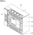
- Fig. 1
- is a perspective view showing a
control device 100. - Fig. 2
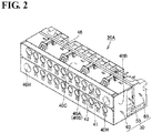
- is a perspective view showing a
terminal block 20A. - Fig. 3
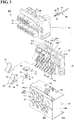
- is a first perspective view (cross-sectional perspective view) showing the exploded
terminal block 20A. - Fig. 4
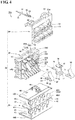
- is a second perspective view (cross-sectional perspective view) showing the exploded
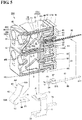
terminal block 20A. - Fig. 5
- is a cross-sectional perspective view showing the
terminal block 20A. - Fig. 6
- is a cross-sectional view showing the
terminal block 20A. - Fig. 7
- is a cross-sectional view illustrating operations performed when a
wiring member 11 is fixed to theterminal block 20A. - Fig. 8
- is a perspective view showing a situation when a force acts on the
wiring member 11 fixed to theterminal block 20A in a direction in which thewiring member 11 is twisted. - Fig. 9
- is a perspective view showing an
inner panel 50 applied to a terminal block in a comparative example. - Fig. 10
- is a cross-sectional view showing an
inner panel 50 and the like applied to a terminal block in a non-claimed modification of an embodiment. - Fig. 11
- is a perspective view showing an
inner panel 50 and the like applied to a terminal block in a non-claimed modification of an embodiment. - Hereinafter, an embodiment will be described with reference to the drawings. The same components and equivalent components are given the same reference numerals, and a redundant description is not repeated in some cases.
-
Fig. 1 is a perspective view showing acontrol device 100. Thecontrol device 100 includes adisplay panel 10P andterminal blocks main body unit 10, and can function as a PLC (programmable logic controller). - The
terminal block 20A may be a means for ensuring electrical connection between thecontrol device 100 and an external device such as a sensor, and a plurality of wiring members (not shown) for transmitting an input signal to thecontrol device 100 are connected to theterminal block 20A. Theterminal block 20B may be a means for ensuring electrical connection between thecontrol device 100 and an external device such as a personal computer, and a plurality of wiring members (not shown) for transmitting an output signal are connected to theterminal block 20B. - The
terminal blocks terminal block 20A will be described below and a description of theterminal block 20B is not repeated. Specifically, a configuration of theterminal block 20A in this embodiment will be described with reference toFigs. 2 to 6 . Effects of theterminal block 20A will be described later with reference toFigs. 7 and8 . -
Fig. 2 is a perspective view showing theterminal block 20A.Figs. 3 and4 are perspective views (cross-sectional perspective views) showing the explodedterminal block 20A.Figs. 5 and6 are respectively a cross-sectional perspective view and a cross-sectional view showing the explodedterminal block 20A. Theterminal block 20A includes a housing 30 (Figs. 2 to 4 ), a terminal fitting 70 (Figs. 3 to 5 ), an electrode member 80 (Figs. 3 to 5 ), and a plate spring 90 (Figs. 3 to 5 ). The overall shape of theterminal block 20A is substantially cuboidal (seeFig. 2 ). - The housing 30 (
Figs. 3 to 5 ) is constituted by combining afront panel 40, aninner panel 50, and aback panel 60. - As shown in
Figs. 3 to 5 , thefront panel 40 includes afront portion 40A,side portions 40B (Figs. 2 and3 ), anupper surface portion 40C, abottom portion 40D, and amiddle portion 40E (Figs. 4 and5 ). - The
front portion 40A has a plate shape, and constitutes afront surface 40S of thefront panel 40. Thefront portion 40A is provided with a plurality of throughholes 41, a plurality of throughholes 42, and a pair ofopenings 40H (Figs. 1 and2 ) that pass through thefront portion 40A. Screws (not shown) for fixing the entireterminal block 20A (Fig. 2 ) to themain body unit 10 of the control device 100 (Fig. 1 ) are inserted into theopenings - As shown in
Figs. 1 and2 , the plurality of throughholes 41 are formed side-by-side in two rows along a direction parallel to a longitudinal direction of theterminal block 20A. The plurality of throughholes 42 are formed side-by-side in two rows along the direction parallel to the longitudinal direction of theterminal block 20A such that the throughholes 41 and the throughholes 42 have a one-to-one correspondence relation. One of the throughholes 42 is always located directly below one of the through holes 41. The plurality of throughholes 41 each have a circular shape, and the plurality of throughholes 42 each have a rectangular shape. - The
upper surface portion 40C, thebottom portion 40D, and themiddle portion 40E of thefront panel 40 each have a plate shape (seeFig. 5 ), and theupper surface portion 40C, thebottom portion 40D, and themiddle portion 40E are disposed in parallel to each other. Theupper surface portion 40C extends from an upper end of thefront portion 40A toward the back, and thebottom portion 40D extends from a lower end of thefront portion 40A toward the back. Themiddle portion 40E extends from a middle position of thefront portion 40A toward the back. - A plurality of partition walls 45 (
Figs. 4 and5 ) are provided on the back side of thefront portion 40A of thefront panel 40. The plurality ofpartition walls 45 are parallel to theside portions 40B (Fig. 3 ) of thefront panel 40. In other words, the plurality ofpartition walls 45 are disposed orthogonal to theupper surface portion 40C, thebottom portion 40D, and themiddle portion 40E. - The plurality of
partition walls 45 are disposed in the longitudinal direction of theterminal block 20A at approximately equal intervals, and define spaces formed between theupper surface portion 40C and themiddle portion 40E in a plurality ofaccommodation portions 43, and define spaces formed between themiddle portion 40E and thebottom portion 40D in the plurality ofaccommodation portions 43. - One of the
accommodation portions 43 is defined between a pair ofadjacent partition walls 45, thefront portion 40A, theupper surface portion 40C, themiddle portion 40E, and the inner panel 50 (an inner wall portion 52) (Fig. 5 ). Similarly, anotheraccommodation portion 43 is defined between a pair ofadjacent partition walls 45, thefront portion 40A, themiddle portion 40E, thebottom portion 40D, and the inner panel 50 (an inner wall portion 52) (Fig. 5 ). - The
accommodation portions 43 defined as described above are located inside thehousing 30 when viewed from thefront portion 40A (seeFig. 2 ), and one of the throughholes 41 and one of the throughholes 42 extend from thefront portion 40A (front surface 40S) of thefront panel 40 to one of the accommodation portions 43 (seeFigs. 4 and5 ). - The
upper surface portion 40C of thefront panel 40 is also provided with a plurality of openings 46 (Figs. 3 to 5 ). Theopenings 46 engage with protrusions 57 (Figs. 3 to 5 ) provided on anupper surface 51U of theinner panel 50. When theopenings 46 engage with theprotrusions 57, thefront panel 40 and theinner panel 50 are fixed to each other. - As shown in
Figs. 3 to 5 , theinner panel 50 is a member disposed between thefront panel 40 and theback panel 60, and includes abase portion 51, inner wall portions 52 (see alsoFig. 8 ),vertical wall portions 53,vertical groove portions 54,ribs protrusions 57. - The
base portion 51 extends in a plate shape along the longitudinal direction of theinner panel 50, andopenings 50H (Figs. 3 and4 ) are each provided near the two ends in the longitudinal direction of thebase portion 51. Theopenings front panel 40 and theinner panel 50 are fixed to each other, and screws (not shown) for fixing the entireterminal block 20A (Fig. 2 ) to themain body unit 10 of the control device 100 (Fig. 1 ) are inserted into theopenings - As shown in
Fig. 6 , theinner wall portion 52 of theinner panel 50 is provided at a position that intersects with (herein, is orthogonal to) a direction in which anaxis 41T of the throughhole 41 extends (an axis direction). That is, theinner wall portion 52 defines oneaccommodation portion 43 together with a pair ofadjacent partition walls 45, thefront portion 40A, theupper surface portion 40C, and themiddle portion 40E. Similarly, also the otherinner wall portions 52 defineother accommodation portions 43 together with a pair ofadjacent partition walls 45, thefront portion 40A, themiddle portion 40E, and thebottom portion 40D. - The
inner wall portion 52 is provided with, as a portion of a constituent element of theinner wall portion 52, a U-shaped recessedgroove 52U in which a side in the upward direction is open and a side in the downward direction is closed. The "downward direction" herein corresponds to a direction in which aplate spring portion 93 of theplate spring 90 undergoes deflection deformation, which will be described later, when the wiring member 11 (seeFig. 7 ) is inserted into theaccommodation portion 43. The "upward direction" herein corresponds to a direction in which a restoring force of elastic deformation of theplate spring portion 93 of theplate spring 90 acts. - The U-shaped recessed
groove 52U includes a first side wall portion 52U1, a second side wall portion 52U2, and a curved surface portion that connects their lower ends. In other words, the first side wall portion 52U1 and the second side wall portion 52U2 are formed in the recessedgroove 52U. Although details will be described later, theplate spring portion 93 of theplate spring 90 and theterminal portion 72 of the terminal fitting 70 are disposed in theaccommodation portion 43, and hold the wiring member 11 (Fig. 7 ) inserted at a position between theterminal portion 72 and theplate spring portion 93. - The first side wall portion 52U1 and the second side wall portion 52U2 face each other in a direction that intersects with (herein, the direction perpendicular to the paper plane of
Fig. 7 ) a direction in which theterminal portion 72 and theplate spring portion 93 hold the wiring member 11 (herein, the direction indicated by the arrow AR shown inFig. 7 ). In the present embodiment, the first side wall portion 52U1 and the second side wall portion 52U2 are orthogonal to theupper surface portion 40C, thebottom portion 40D, and themiddle portion 40E. - Although details will be described later, a movement of a portion (an electrode portion 12) of the wiring member 11 (
Fig. 7 ) that is inserted into theaccommodation portion 43 is curbed by disposing the portion (the electrode portion 12) of thewiring member 11 that is inserted into theaccommodation portion 43 between the first side wall portion 52U1 and the second side wall portion 52U2. "Movement" here refers to a movement in a direction that intersects with (herein, the direction perpendicular to the paper plane ofFig. 7 ) a direction in which theterminal portion 72 and theplate spring portion 93 hold the wiring member 11 (herein, the direction indicated by the arrow AR shown inFig. 7 ). - The vertical wall portion 53 (
Figs. 3 ,4 , and8 ) has a plate shape, and extends from thebase portion 51 toward the front. Thevertical wall portion 53 is orthogonal to theupper surface portion 40C, thebottom portion 40D, and themiddle portion 40E of thefront panel 40. Thevertical groove portion 54 is formed between theinner wall portion 52 and thevertical wall portion 53, and provides a recessed space. The partition walls 45 (seeFig. 4 ) of thefront panel 40 are disposed inside thevertical groove portion 54 in a state in which thefront panel 40 and theinner panel 50 are fixed to each other. - The
ribs inner wall portion 52 toward the front. Theribs base portion 51.Upper surfaces ribs ribs upper surfaces upper surfaces -
Openings 51H are provided at positions of thebase portion 51 located between theribs base portion 51. Although details will be described later, an L-shapedportion 74 of the terminal fitting 70 is inserted into theopening 51H (seeFigs. 5 and6 ). Theupper surface 51U of thebase portion 51 is also provided with a plurality of protrusions 57 (Figs 3 to 5 ). When theopenings 46 provided in theupper surface portion 40C of thefront panel 40 engage with theprotrusions 57 provided in the base portion 51 (theupper surface 51U) of theinner panel 50, thefront panel 40 and theinner panel 50 are fixed to each other. - As shown in
Fig. 5 , a recessedportion 51E is provided on the front side of the base portion 51 (see alsoFig. 4 ). The recessedportion 51E extends in the form of a groove along the longitudinal direction of thebase portion 51. The recessedportion 51E has a shape corresponding to the front end portion of themiddle portion 40E of thefront panel 40, and themiddle portion 40E of thefront panel 40 is disposed inside the recessedportions 51E in a state in which thefront panel 40 and theinner panel 50 are fixed to each other (seeFig. 5 ). - As shown in
Fig. 5 , a plurality of plate-shapedportions 58 are provided on the back side of thebase portion 51, and arecess 59 is formed between adjacent plate-shapedportions back panel 60 is provided with protruding portions 62 (Figs. 3 and4 ), and the protrudingportions 62 are disposed inside therecesses 59 in a state in which theinner panel 50 and theback panel 60 are fixed to each other (seeFig. 5 ). - As shown in
Figs. 3 to 5 , theback panel 60 is a member that is disposed on the back side of theinner panel 50, and includes abase portion 61, the protrudingportions 62, andopenings 63. - The
base portion 61 extends in a plate shape along the longitudinal direction of theback panel 60, andopenings 60H (seeFigs. 3 and4 ) are provided near the two ends in the longitudinal direction of thebase portion 61. Theopenings front panel 40, theinner panel 50, and theback panel 60 are fixed to each other, and screws (not shown) for fixing the entireterminal block 20A (Fig. 2 ) to themain body unit 10 of the control device 100 (Fig. 1 ) are inserted into theopenings - The protruding
portions 62 have a substantially cuboidal shape, and extend from thebase portion 61 toward the front. The protrudingportions 62 have a hollow shape, and a front end portion of theelectrode member 80, which will be described later, is disposed inside one of the protruding portions 62 (seeFig. 5 ). Theopenings 63 pass through sites of the protrudingportions 62 on the front side. Although details will be described later, an L-shapedportion 74 of the terminal fitting 70 is inserted into the opening 63 (seeFig. 5 ). - As shown in
Figs. 3 to 5 , the terminal fitting 70 includes a risingwall portion 71, aterminal portion 72, abase portion 73, and the L-shapedportion 74. Theterminal fitting 70 is disposed in theaccommodation portion 43 together with theplate spring 90, which will be described later. - Th rising
wall portion 71, theterminal portion 72, and thebase portion 73 each have a substantially flat-plate shape. Theterminal portion 72 extends from the upper end of the risingwall portion 71 in a direction that is substantially orthogonal to the risingwall portion 71, and thebase portion 73 extends from the lower end of the risingwall portion 71 in a direction that is substantially orthogonal to the risingwall portion 71. The overall shape of the risingwall portion 71, theterminal portion 72, and thebase portion 73 resembles a C-shape, and the L-shapedportion 74 extends from thebase portion 73 toward the back. - The surface of the
base portion 73 is provided withprotrusions base portion 91 of theplate spring 90 is provided withopenings protrusions base portion 91 of theplate spring 90 is placed on thebase portion 73 of the terminal fitting 70, theprotrusions openings 95 and 96 (seeFig. 6 ), and thus the position of theplate spring 90 with respect to the terminal fitting 70 is determined (defined). - The L-shaped
portion 74 is connected to a portion of the back side of thebase portion 73, extends upward from the portion of the back side of thebase portion 73, linearly extends from a front end portion of this extension portion toward the back side, and the overall shape of the L-shapedportion 74 is substantially L-shaped. As described above, theopening 51H is provided at a position located between theribs inner panel 50 while passing through thebase portion 51. Furthermore, the protrudingportions 62 of theback panel 60 are provided with theopenings 63. The L-shapedportion 74 of the terminal fitting 70 is inserted into theopenings 51H and 63 (seeFig. 5 ). - As shown in
Figs. 3 to 5 , theelectrode member 80 includes a flat-plate portion 81, aU-shaped portion 82, and a pair of holdingpieces - The flat-
plate portion 81 extends linearly, and one end 81T (Fig. 5 ) of the flat-plate portion 81 is electrically connected to a control board disposed in themain body unit 10 of the control device 100 (Fig. 1 ). TheU-shaped portion 82 is provided at theother end 81S of the flat-plate portion 81. The pair of holdingpieces plate portion 81 with respect to theU-shaped portion 82. - As described above, the
back panel 60 is provided with the protrudingportions 62. TheU'shaped portion 82 and the holdingpieces electrode member 80 are disposed inside the protruding portion 62 (seeFig. 5 ). The L-shapedportion 74 of the terminal fitting 70 is inserted in theopenings pieces electrode member 80 hold the L-shapedportion 74 of the terminal fitting 70, the terminal fitting 70 and theelectrode member 80 are electrically connected to each other. - Referring to
Figs. 5 and6 , as described above, theaccommodation portions 43 are defined between thefront panel 40 and the inner panel 50 (between theupper surface portion 40C and themiddle portion 40E) in a state in which thefront panel 40 is fixed to theinner panel 50. In this state, a gap S is formed between the lower surface of the rib 56 (and the lower surface of the rib 55 (not shown)) and the upper surface of themiddle portion 40E (seeFig. 5 ). - In a state in which the members are assembled together as the
terminal block 20A (in the state of the completedterminal block 20A), thebase portion 73 of the terminal fitting 70 is disposed inside the gap S. Furthermore, theterminal portion 72 of the terminal fitting 70 faces the lower surface of theupper surface portion 40C (seeFigs. 5 and6 ). The same applies to theaccommodation portions 43 defined between themiddle portion 40E and thebottom portion 40D and theterminal fittings 70 disposed in theseaccommodation portions 43. - As shown in
Figs. 3 to 5 , theplate spring 90 includes thebase portion 91, acurved portion 92, and aplate spring portion 93. Theplate spring 90 is disposed in theaccommodation portion 43 together with theterminal fitting 70. - The
base portion 91 and theplate spring portion 93 each have a substantially flat-plate shape, and thecurved portion 92 is provided between thebase portion 91 and theplate spring portion 93. As described above, thebase portion 91 of theplate spring 90 is provided with theopenings protrusions terminal fitting 70. When thebase portion 91 of theplate spring 90 is placed on thebase portion 73 of the terminal fitting 70, theprotrusions openings 95 and 96 (seeFig. 6 ), and thus the position of theplate spring 90 with respect to the terminal fitting 70 is determined (defined). - The
accommodation portions 43 are defined between thefront panel 40 and the inner panel 50 (between theupper surface portion 40C and themiddle portion 40E) in a state in which thefront panel 40 is fixed to theinner panel 50. In this state, a gap S is formed between the lower surface of the rib 56 (and the lower surface of the rib 55 (not shown)) and the upper surface of themiddle portion 40E (seeFig. 5 ). Thebase portion 91 of theplate spring 90 is disposed inside the gap S together with thebase portion 73 of theterminal fitting 70. - The
curved portion 92 is substantially C-shaped in a cross-sectional view, and is connected to an end of thebase portion 91 on the front side. Theplate spring portion 93 is connected to the upper end of thecurved portion 92. Theplate spring portion 93 is inclined such that the upper portion of theplate spring portion 93 is located on the back side, and the lower portion of theplate spring portion 93 is located on the front side. One end of theplate spring portion 93 is supported by thecurved portion 92, and theplate spring portion 93 can undergo deflection deformation like a plate spring. - For example, when the
plate spring portion 93 is pressed by the wiring member 11 (see thewiring member 11 inFig. 7 ) inserted into theaccommodation portion 43 through the throughhole 41, theplate spring portion 93 undergoes deflection deformation. Alternatively, when theplate spring portion 93 is pressed by a tool (a flathead screwdriver or the like) inserted into theaccommodation portion 43 through the throughhole 42, theplate spring portion 93 undergoes deflection deformation. - The
plate spring portion 93 includes abase portion 93S (Fig. 6 ) that forms a fixed end of deflection deformation, and afront end portion 93T (Fig. 6 ) that forms a free-end of deflection deformation. Theplate spring portion 93 is disposed in theaccommodation portion 43 such that thefront end portion 93T is located closer to the throughhole 41 than thebase portion 93S, and thebase portion 93S is located closer to the throughhole 42 than thefront end portion 93T. - The
plate spring portion 93 is spaced apart from and faces theupper surface ribs plate spring 90 is disposed in the accommodation portion 43 (seeFig. 6 ). Theribs 55 and 56 (upper surfaces accommodation portion 43 can curb an amount of deflection deformation (the maximum deflection deformation amount) of theplate spring portion 93 of theplate spring 90. - The
front end portion 93T of theplate spring portion 93 faces theterminal portion 72 of the terminal fitting 70, and is capable of holding, together with theterminal portion 72, the wiring member (see thewiring member 11 inFig. 7 ) inserted into theaccommodation portion 43 through the through hole 41 (seeFig. 7 ). In the present embodiment, thefront end portion 93T of theplate spring portion 93 is in contact with theterminal portion 72 of the terminal fitting 70 in a state in which the wiring member 11 (Fig. 7 ) is not inserted into the throughhole 41 and the tool 14 (Fig. 8 ) is not inserted in the throughhole 42, that is, in the natural state of the plate spring 90 (seeFig. 6 ). - In the present embodiment, a member (the terminal fitting 70) that constitutes the
terminal portion 72 and a member (the plate spring 90) that constitutes theplate spring portion 93 are constituted by separate members, and are disposed in theaccommodation portion 43 in a state in which these members are assembled with each other. The present invention is not limited to such a configuration, and the member that constitutes theterminal portion 72 and the member that constitutes theplate spring portion 93 may also be constituted by a single member. - Referring to
Figs. 7 and8 , when thewiring member 11 such as a single wire or a rod terminal is fixed to theterminal block 20A, thewiring member 11 passes through the throughhole 41, and is inserted at a position between theplate spring portion 93 of theplate spring 90 and theterminal portion 72 of theterminal fitting 70. Thewiring member 11 is inserted until coming into contact with the inner wall portion 52 (specifically, an inner surface 52U3 in the recessedgroove 52U) while subjecting theplate spring portion 93 to deflection deformation as shown inFigs. 7 and8 . - The
wiring member 11 has anelectrode portion 12 and a coveredportion 13, and when theelectrode portion 12 is held between theplate spring portion 93 of theplate spring 90 and theterminal portion 72 of the terminal fitting 70, thewiring member 11 is fixed. Thewiring member 11 is pressed against theterminal portion 72 of the terminal fitting 70 by an elastic restoring force of the plate spring 90 (the plate spring portion 93), and thus thewiring member 11 is electrically connected to theterminal fitting 70. - When the
wiring member 11 is removed, thewiring member 11 can be pulled out by subjecting theplate spring portion 93 that presses thewiring member 11 against theterminal portion 72 to undergo deflection deformation in a direction away from the wiring member 11 (the terminal portion 72). It is possible to easily dispose thewiring member 11 at the position located between theplate spring portion 93 and theterminal portion 72 by subjecting theplate spring portion 93 to undergo deflection deformation in a direction away from theterminal portion 72 not only in the case where thewiring member 11 is pulled out but also in the case where thewiring member 11 with low rigidity is inserted toward theterminal portion 72. By inserting a tool (for example, a flathead screwdriver or the like) into theaccommodation portion 43 through the throughhole 42 as a specific means, theplate spring portion 93 can be subjected to deflection deformation easily in a direction away from theterminal portion 72. - In the present embodiment, the
plate spring portion 93 of theplate spring 90 and theterminal portion 72 of the terminal fitting 70 hold the wiring member 11 (Fig. 7 ) inserted at a position between theterminal portion 72 and theplate spring portion 93. The first side wall portion 52U1 and the second side wall portion 52U2 face each other in a direction that intersects with (herein, the direction perpendicular to the paper plane ofFig. 7 ) a direction in which theterminal portion 72 and theplate spring portion 93 hold the wiring member 11 (herein, the direction indicated by the arrow AR shown inFig. 7 ). - A movement of a portion (the electrode portion 12) of the wiring member 11 (
Fig. 7 ) that is inserted into theaccommodation portion 43 is curbed by disposing the portion (the electrode portion 12) of thewiring member 11 that is inserted into theaccommodation portion 43 between the first side wall portion 52U1 and the second side wall portion 52U2. "Movement" here refers to a movement in a direction that intersects with (herein, the direction perpendicular to the paper plane ofFig. 7 ) a direction in which theterminal portion 72 and theplate spring portion 93 hold the wiring member 11 (herein, the direction indicated by the arrow AR shown inFig. 7 ). - Thus, in the
terminal block 20A in the present embodiment, in a state in which thewiring member 11 is inserted between theplate spring portion 93 and theterminal portion 72, a movement in a direction that intersects with (herein, a direction orthogonal to) a direction in which theplate spring portion 93 and theterminal portion 72 hold thewiring member 11 is curbed by the first side wall portion 52U1 and the second side wall portion 52U2 while thewiring member 11 is subjected to holding forces from theplate spring portion 93 and theterminal portion 72. - Even if a twisting force (see arrow DR in
Fig. 8 ) repeatedly acts on thewiring member 11, thewiring member 11 hardly moves in a direction in which theplate spring portion 93 and theterminal portion 72 hold thewiring member 11, and thewiring member 11 hardly moves in a direction that intersects with (herein, a direction orthogonal to) the direction in which theplate spring portion 93 and theterminal portion 72 hold thewiring member 11. - Thus, the possibility that the
wiring member 11 will come off from a position between theplate spring portion 93 and theterminal portion 72 is effectively reduced, compared to the case where neither the first side wall portion 52U1 nor the second side wall portion 52U2 are provided in theaccommodation portion 43. Theterminal block 20A having such a configuration is capable of exhibiting high reliability as a means for connecting the control device 100 (Fig. 1 ) and another device via thewiring member 11. -
Fig. 9 is a perspective view showing aninner panel 50 applied to a terminal block in a first comparative example. - In the above-described embodiment, the
accommodation portion 43 is provided with theinner wall portion 52 that intersects with a direction in which theaxis 41T of the throughhole 41 extends (the axis direction), theinner wall portion 52 is provided with the U-shaped recessedgroove 52U in which a side in the upward direction is open and a side in the downward direction is closed, and the first side wall portion 52U1 and the second side wall portion 52U2 are formed in the U-shaped recessedgroove 52U. - As shown in
Fig. 9 , the first side wall portion 52U1 and the second side wall portion 52U2 may also be formed in a recessedgroove 52U having a circular shape in a front view. With this configuration, it is also possible to obtain effects that are substantially similar to those of the above-described embodiment. - Note that the recessed
groove 52U has a U-shape in the above-described embodiment. A portion (a portion 52U4 shown inFig. 9 ) outward of a portion of the inner wall portion 52 (the recessedgroove 52U) in which the front end portion of thewiring member 11 is disposed is a space in the embodiment (seeFig. 8 ), and is open. When thewiring member 11 is inserted between theplate spring portion 93 and theterminal portion 72, thewiring member 11 is subjected to a force caused by an elastic restoring force of theplate spring portion 93, and easily comes into contact with the portion 52U4 shown inFig. 9 . Because the portion outward of the portion in which the front end portion of thewiring member 11 is disposed is open in the above-described embodiment, the above-described embodiment has an advantage in that an operator can easily dispose thewiring member 11 in the recessedgroove 52U and easily perform a wiring operation. -
Figs. 10 and 11 are respectively a cross-sectional view and a perspective view showing aninner panel 50 and the like applied to a terminal block in a non-claimed modification of an embodiment. - In the above-described embodiment, the
plate spring portion 93 includes abase portion 93S that constitutes a fixed end of deflection deformation and afront end portion 93T that constitutes a free-end of deflection deformation when theplate spring portion 93 is pressed by thewiring member 11 inserted into theaccommodation portion 43 through the throughhole 41, and the first side wall portion 52U1 and the second side wall portion 52U2 are located opposite the throughhole 41 with respect to thefront end portion 93T of theplate spring portion 93 in a state in which thewiring member 11 is not inserted into the through hole 41 (seeFig. 6 ). In other words, thefront end portion 93T of theplate spring portion 93 is located between the throughhole 41, and the first side wall portion 52U1 and the second side wall portion 52U2 in a state in which thewiring member 11 is not inserted into the throughhole 41. - As shown in
Figs. 10 and 11 , in the present non-claimed modification, a lower surface of anupper surface portion 40C is provided with a third side wall portion 40W1 (Fig. 11 ) and a fourth side wall portion 40W2 that extend downward. The third side wall portion 40W1 (Fig. 11 ) and the fourth side wall portion 40W2 are positioned on the side of a throughhole 41 with respect to afront end portion 93T of aplate spring portion 93. In other words, the third side wall portion 40W1 (Fig. 11 ) and the fourth side wall portion 40W2 are located in anaccommodation portion 43, and are located between aninner surface 43U (Fig. 10 ) that defines theaccommodation portion 43 and thefront end portion 93T of theplate spring portion 93 in afront portion 40A of afront panel 40. - As a result of a portion (an electrode portion 12) of a wiring member 11 (
Fig. 11 ) that is inserted into theaccommodation portion 43 being disposed between the third side wall portion 40W1 and the fourth side wall portion 40W2, a movement of the portion (the electrode portion 12) of thewiring member 11 that is inserted into theaccommodation portion 43 is curbed. "Movement" here refers to a movement in a direction that intersects with (the direction perpendicular to the paper plane ofFig. 11 ) a direction in which aterminal portion 72 and theplate spring portion 93 hold thewiring member 11. - Even if a twisting force (see the arrow DR in
Fig. 8 ) repeatedly acts on thewiring member 11, thewiring member 11 hardly moves in the direction in which theplate spring portion 93 and theterminal portion 72 hold thewiring member 11, and thewiring member 11 hardly moves, due to the third side wall portion 40W1 and the fourth side wall portion 40W2, in a direction that intersects with (herein, a direction orthogonal to) the direction in which theplate spring portion 93 and theterminal portion 72 hold thewiring member 11. - In addition to the first side wall portion 52U1 and the second side wall portion 52U2, the first side wall portion 40W1 and the second side wall portion 40W2 are provided in the
accommodation portion 43 inFigs. 10 and 11 .. - Although an embodiment was described above, the content disclosed above is to be considered exemplary in all respects and in no way limiting. The technical scope of the present invention is indicated by the scope of the claims, and all changes that come within the meaning of the claims are intended to be embraced therein.
-
- 10
- Main body unit
- 10P
- Display panel
- 11
- Wiring member
- 12
- Electrode portion
- 13
- Covered portion
- 14
- Tool
- 20A, 20B
- Terminal block
- 30
- Housing
- 40
- Front panel
- 40A
- Front portion
- 40B
- Side portion
- 40C
- Upper surface portion
- 40D
- Bottom portion
- 40E
- Middle portion
- 40H, 46, 50H, 51H, 60H, 63, 95, 96
- Opening
- 40S
- Front surface
- 40W1, 52U1
- First side wall portion
- 40W2, 52U2
- Second side wall portion
- 41, 42
- Through hole
- 41T
- Axis
- 43
- Accommodation portion
- 43U, 52U3
- Inner surface
- 45
- Partition wall
- 50
- Inner panel
- 51, 61
- Base portion
- 51E
- Recessed portion
- 51U, 55S, 56S
- Upper surface
- 52
- Inner wall portion
- 52U
- Recessed groove
- 52U4
- Portion
- 53
- Vertical wall portion
- 54
- Vertical groove portion
- 55, 56
- Rib
- 57, 75, 76
- Protrusion
- 58
- Plate-shaped portion
- 59
- Recess
- 60
- Back panel
- 62
- Protruding portion
- 70
- Terminal fitting
- 71
- Rising wall portion
- 72
- Terminal portion
- 73
- Base portion
- 74
- L-shaped portion
- 80
- Electrode member
- 81
- Flat-plate portion
- 81S
- Another end
- 81T
- One end
- 82
- U-shaped portion
- 83, 84
- Holding piece
- 90
- Plate spring
- 91
- Base portion
- 92
- Curved portion
- 93
- Plate spring portion
- 93S
- Base portion
- 93T
- Front end portion
- 100
- Control device
- DR
- Arrow
- S
- Gap
Claims (1)
- A terminal block (20A) comprising:a housing (30) including a front portion (40A), an accommodation portion (43) located on an inner side when viewed from the front portion (40A), and a through hole (41) that extends from the front portion (40A) to the accommodation portion (43);a terminal portion (72) disposed in the accommodation portion (43) of the housing (30); anda plate spring portion (93) that is disposed in the accommodation portion (43) of the housing (30) and is adapted to, together with the terminal portion (72), hold a wiring member (11) when the wiring member (11) is inserted into the accommodation portion (43) through the through hole (41),wherein the accommodation portion (43) is formed by combining together a front panel (40) forming the front portion (40A), and an inner panel (50) disposed on the inner side when viewed from the front panel (40),the accommodation portion (43) is provided with an inner wall portion (52) that intersects with an axis (41T) of the through hole (41),the plate spring portion (93) includes a base portion (93S) that constitutes a fixed end of deflection deformation and a front end portion (93T) that constitutes a free-end of deflection deformation when the plate spring portion (93) is pressed by the wiring member (11) inserted into the accommodation portion (43) through the through hole (41), anda first side wall portion (52U1) and a second side wall portion (52U2) are formed in the accommodation portion (43) of the housing (30), the first side wall portion (52U1) and the second side wall portion (52U2) facing each other in an intersecting direction that intersects with a direction in which the plate spring portion (93) and the terminal portion (72) hold the wiring member (11) and intersects with the axis (41T) of the through hole,characterized in thatthe first side wall portion (52U1) and the second side wall portion (52U2) are located opposite the through hole (41) with respect to the front end portion (93T) of the plate spring portion (93) in a state in which the wiring member (11) is not inserted into the through hole (41), andif a direction in which the plate spring portion (93) undergoes deflection deformation when the wiring member (11) is inserted into the accommodation portion (43) is regarded as a downward direction, and a direction in which a restoring force of elastic deformation of the plate spring portion (93) acts is regarded as an upward direction,the inner wall portion (52) is provided with a U-shaped recessed groove (52U) in which a side in the upward direction is open and a side in the downward direction is closed,the first side wall portion (52U1) and the second side wall portion (52U2) are formed in the recessed groove (52U), anda width, in the intersecting direction, of the recessed groove (52U), which is a distance between the first side wall portion (52U1) and the second side wall portion (52U2), is smaller than a width, in the intersecting direction, of the front-end portion (93T) of the plate spring portion (93) such thata movement, in the intersecting direction, of a portion of the wiring member (11) that is inserted into the accommodation portion (43) is curbed when the portion of the wiring member (11) that is inserted into the accommodation portion (43) is disposed between the first side wall portion (52U1) and the second side wall portion (52U2) in the recessed groove (52U).
Applications Claiming Priority (2)
| Application Number | Priority Date | Filing Date | Title |
|---|---|---|---|
| JP2016194249A JP6726074B2 (en) | 2016-09-30 | 2016-09-30 | Terminal block |
| PCT/JP2017/034709 WO2018062163A1 (en) | 2016-09-30 | 2017-09-26 | Terminal block |
Publications (3)
| Publication Number | Publication Date |
|---|---|
| EP3522304A1 EP3522304A1 (en) | 2019-08-07 |
| EP3522304A4 EP3522304A4 (en) | 2019-11-27 |
| EP3522304B1 true EP3522304B1 (en) | 2021-08-18 |
Family
ID=61760397
Family Applications (1)
| Application Number | Title | Priority Date | Filing Date |
|---|---|---|---|
| EP17856113.0A Active EP3522304B1 (en) | 2016-09-30 | 2017-09-26 | Terminal block |
Country Status (5)
| Country | Link |
|---|---|
| US (1) | US10665968B2 (en) |
| EP (1) | EP3522304B1 (en) |
| JP (1) | JP6726074B2 (en) |
| CN (1) | CN109804507B (en) |
| WO (1) | WO2018062163A1 (en) |
Families Citing this family (8)
| Publication number | Priority date | Publication date | Assignee | Title |
|---|---|---|---|---|
| JP2018056076A (en) * | 2016-09-30 | 2018-04-05 | オムロン株式会社 | Terminal block |
| JP2020047464A (en) | 2018-09-19 | 2020-03-26 | 富士電機機器制御株式会社 | Connection structure of electrical equipment |
| JP7006575B2 (en) * | 2018-12-11 | 2022-01-24 | オムロン株式会社 | Terminal module and terminal block |
| JP7353062B2 (en) * | 2019-04-18 | 2023-09-29 | Idec株式会社 | Terminal units and electrical components |
| DE102019126662A1 (en) * | 2019-10-02 | 2021-04-08 | Phoenix Contact Gmbh & Co. Kg | Connection unit with actuating elements and conductor connection openings arranged in two rows |
| JP7322689B2 (en) * | 2019-12-12 | 2023-08-08 | 住友電装株式会社 | Terminal block |
| CN112993633B (en) * | 2021-03-02 | 2025-07-25 | 厦门广泓工贸有限公司 | Rubber shell for mounting connecting terminal and connecting terminal |
| USD1037169S1 (en) * | 2021-11-30 | 2024-07-30 | Schweitzer Engineering Laboratories, Inc | Terminal block connection device |
Family Cites Families (21)
| Publication number | Priority date | Publication date | Assignee | Title |
|---|---|---|---|---|
| JPS57191966A (en) * | 1981-05-20 | 1982-11-25 | Kawaguchi Kinzoku Kogyo Kk | Connecting terminal for single wire |
| US4566748A (en) * | 1984-09-17 | 1986-01-28 | Matsushita Electric Works, Ltd. | Connector |
| GB9100135D0 (en) | 1991-01-04 | 1991-02-20 | Amp Great Britain | Electrical connector and an electrical contact element |
| EP0616386A3 (en) | 1993-03-18 | 1996-03-13 | Tadao Tozuka | Plug-in connector. |
| DE19654611B4 (en) * | 1996-12-20 | 2004-09-30 | Wago Verwaltungsgesellschaft Mbh | Spring clamp connection for electrical conductors |
| JP2000048875A (en) | 1998-04-22 | 2000-02-18 | Fuji Electric Co Ltd | Circuit breaker wire connection device |
| US6746286B2 (en) | 2002-03-06 | 2004-06-08 | Ideal Industries, Inc. | Push-in wire connector |
| JP3855833B2 (en) * | 2002-04-23 | 2006-12-13 | オムロン株式会社 | Wire connection connector |
| US6832938B2 (en) * | 2002-12-13 | 2004-12-21 | Tyco Electronics Corporation | Electrical connector with integral wire release member |
| DE20308863U1 (en) * | 2003-06-06 | 2003-08-21 | Ria Btr Produktions Gmbh | terminal |
| JP4071174B2 (en) * | 2003-07-25 | 2008-04-02 | 松下電工株式会社 | Lamp socket |
| US7410386B2 (en) * | 2005-03-03 | 2008-08-12 | Tyco Electronics Corporation | Pluggable screwless wire connector system |
| EP1737070A3 (en) * | 2005-06-21 | 2007-02-07 | Ideal Industries Inc. | Eledtrical disconnect with push-in connectors |
| DE202006009460U1 (en) * | 2005-10-29 | 2007-03-15 | Weidmüller Interface GmbH & Co. KG | Connection device for conductors |
| US7281942B2 (en) * | 2005-11-18 | 2007-10-16 | Ideal Industries, Inc. | Releasable wire connector |
| WO2008095669A1 (en) | 2007-02-05 | 2008-08-14 | Phoenix Contact Gmbh & Co. Kg | Junction box and connecting box for a solar module |
| US7722384B2 (en) * | 2007-07-09 | 2010-05-25 | Ideal Industries, Inc. | In-line push-in wire connector |
| JP5249608B2 (en) | 2008-03-12 | 2013-07-31 | 株式会社ニチフ端子工業 | Wire connector |
| US7785134B2 (en) * | 2008-12-30 | 2010-08-31 | General Electric Company | Contact terminal for conductors |
| US8944843B2 (en) * | 2012-03-09 | 2015-02-03 | Ideal Industries, Inc. | Electrical connector with a push-in type contact |
| JP2018056076A (en) * | 2016-09-30 | 2018-04-05 | オムロン株式会社 | Terminal block |
-
2016
- 2016-09-30 JP JP2016194249A patent/JP6726074B2/en active Active
-
2017
- 2017-09-26 EP EP17856113.0A patent/EP3522304B1/en active Active
- 2017-09-26 WO PCT/JP2017/034709 patent/WO2018062163A1/en not_active Ceased
- 2017-09-26 CN CN201780053160.4A patent/CN109804507B/en active Active
- 2017-09-26 US US16/329,245 patent/US10665968B2/en active Active
Also Published As
| Publication number | Publication date |
|---|---|
| CN109804507A (en) | 2019-05-24 |
| JP2018056077A (en) | 2018-04-05 |
| EP3522304A1 (en) | 2019-08-07 |
| US20190252807A1 (en) | 2019-08-15 |
| US10665968B2 (en) | 2020-05-26 |
| WO2018062163A1 (en) | 2018-04-05 |
| EP3522304A4 (en) | 2019-11-27 |
| CN109804507B (en) | 2020-10-23 |
| JP6726074B2 (en) | 2020-07-22 |
Similar Documents
| Publication | Publication Date | Title |
|---|---|---|
| EP3522304A1 (en) | Terminal block | |
| US7462076B2 (en) | Terminal block for connecting electrical conductors | |
| US7544103B2 (en) | Terminal block for connecting electrical conductors | |
| US8771004B2 (en) | Miniature spring clamp | |
| EP3522302A1 (en) | Terminal block | |
| JP5682997B2 (en) | Electrical connector | |
| US10085355B2 (en) | Housing mountable on a mounting rail for receiving an electronics module | |
| US20130280928A1 (en) | Power distribution box assembly | |
| US20120258615A1 (en) | Spring terminal, in particular a front terminal | |
| US10297994B2 (en) | Substrate holding structure, electronic component module, and electrical connection box | |
| EP3211227A1 (en) | Drive device and mounting structure thereof | |
| KR20110076897A (en) | Terminal parts | |
| CN101944684A (en) | Connector | |
| US7008260B2 (en) | Cross-connector means for electrical junction boxes and the like | |
| EP3261184B1 (en) | Electrical contact limiter structure of wire connection terminal | |
| US20110237129A1 (en) | Holder-mounting structure | |
| JP2017117703A (en) | Branch connector | |
| CN101170016A (en) | Appliance switchgear and connection terminals for appliance switchgear | |
| CN109390738B (en) | Connector with a locking member | |
| KR20100121950A (en) | Connector having joint terminal | |
| EP2897228A1 (en) | Terminal device and electric outlet using same | |
| JP2006311755A (en) | Busbar mounting structure | |
| KR20160053370A (en) | Electric connector for a power cable | |
| KR20160033156A (en) | Electric connector housing and electric connector | |
| EP2263286B1 (en) | Terminal board with modular contacts |
Legal Events
| Date | Code | Title | Description |
|---|---|---|---|
| STAA | Information on the status of an ep patent application or granted ep patent |
Free format text: STATUS: THE INTERNATIONAL PUBLICATION HAS BEEN MADE |
|
| PUAI | Public reference made under article 153(3) epc to a published international application that has entered the european phase |
Free format text: ORIGINAL CODE: 0009012 |
|
| STAA | Information on the status of an ep patent application or granted ep patent |
Free format text: STATUS: REQUEST FOR EXAMINATION WAS MADE |
|
| 17P | Request for examination filed |
Effective date: 20190228 |
|
| AK | Designated contracting states |
Kind code of ref document: A1 Designated state(s): AL AT BE BG CH CY CZ DE DK EE ES FI FR GB GR HR HU IE IS IT LI LT LU LV MC MK MT NL NO PL PT RO RS SE SI SK SM TR |
|
| AX | Request for extension of the european patent |
Extension state: BA ME |
|
| A4 | Supplementary search report drawn up and despatched |
Effective date: 20191028 |
|
| RIC1 | Information provided on ipc code assigned before grant |
Ipc: H01R 4/48 20060101ALI20191022BHEP Ipc: H01R 9/24 20060101AFI20191022BHEP |
|
| DAV | Request for validation of the european patent (deleted) | ||
| DAX | Request for extension of the european patent (deleted) | ||
| GRAP | Despatch of communication of intention to grant a patent |
Free format text: ORIGINAL CODE: EPIDOSNIGR1 |
|
| STAA | Information on the status of an ep patent application or granted ep patent |
Free format text: STATUS: GRANT OF PATENT IS INTENDED |
|
| INTG | Intention to grant announced |
Effective date: 20210416 |
|
| GRAS | Grant fee paid |
Free format text: ORIGINAL CODE: EPIDOSNIGR3 |
|
| GRAA | (expected) grant |
Free format text: ORIGINAL CODE: 0009210 |
|
| STAA | Information on the status of an ep patent application or granted ep patent |
Free format text: STATUS: THE PATENT HAS BEEN GRANTED |
|
| AK | Designated contracting states |
Kind code of ref document: B1 Designated state(s): AL AT BE BG CH CY CZ DE DK EE ES FI FR GB GR HR HU IE IS IT LI LT LU LV MC MK MT NL NO PL PT RO RS SE SI SK SM TR |
|
| REG | Reference to a national code |
Ref country code: GB Ref legal event code: FG4D |
|
| REG | Reference to a national code |
Ref country code: CH Ref legal event code: EP |
|
| REG | Reference to a national code |
Ref country code: DE Ref legal event code: R096 Ref document number: 602017044463 Country of ref document: DE |
|
| REG | Reference to a national code |
Ref country code: IE Ref legal event code: FG4D Ref country code: AT Ref legal event code: REF Ref document number: 1422464 Country of ref document: AT Kind code of ref document: T Effective date: 20210915 |
|
| REG | Reference to a national code |
Ref country code: LT Ref legal event code: MG9D |
|
| REG | Reference to a national code |
Ref country code: NL Ref legal event code: MP Effective date: 20210818 |
|
| REG | Reference to a national code |
Ref country code: AT Ref legal event code: MK05 Ref document number: 1422464 Country of ref document: AT Kind code of ref document: T Effective date: 20210818 |
|
| PG25 | Lapsed in a contracting state [announced via postgrant information from national office to epo] |
Ref country code: BG Free format text: LAPSE BECAUSE OF FAILURE TO SUBMIT A TRANSLATION OF THE DESCRIPTION OR TO PAY THE FEE WITHIN THE PRESCRIBED TIME-LIMIT Effective date: 20211118 Ref country code: AT Free format text: LAPSE BECAUSE OF FAILURE TO SUBMIT A TRANSLATION OF THE DESCRIPTION OR TO PAY THE FEE WITHIN THE PRESCRIBED TIME-LIMIT Effective date: 20210818 Ref country code: LT Free format text: LAPSE BECAUSE OF FAILURE TO SUBMIT A TRANSLATION OF THE DESCRIPTION OR TO PAY THE FEE WITHIN THE PRESCRIBED TIME-LIMIT Effective date: 20210818 Ref country code: NO Free format text: LAPSE BECAUSE OF FAILURE TO SUBMIT A TRANSLATION OF THE DESCRIPTION OR TO PAY THE FEE WITHIN THE PRESCRIBED TIME-LIMIT Effective date: 20211118 Ref country code: PT Free format text: LAPSE BECAUSE OF FAILURE TO SUBMIT A TRANSLATION OF THE DESCRIPTION OR TO PAY THE FEE WITHIN THE PRESCRIBED TIME-LIMIT Effective date: 20211220 Ref country code: SE Free format text: LAPSE BECAUSE OF FAILURE TO SUBMIT A TRANSLATION OF THE DESCRIPTION OR TO PAY THE FEE WITHIN THE PRESCRIBED TIME-LIMIT Effective date: 20210818 Ref country code: RS Free format text: LAPSE BECAUSE OF FAILURE TO SUBMIT A TRANSLATION OF THE DESCRIPTION OR TO PAY THE FEE WITHIN THE PRESCRIBED TIME-LIMIT Effective date: 20210818 Ref country code: HR Free format text: LAPSE BECAUSE OF FAILURE TO SUBMIT A TRANSLATION OF THE DESCRIPTION OR TO PAY THE FEE WITHIN THE PRESCRIBED TIME-LIMIT Effective date: 20210818 Ref country code: FI Free format text: LAPSE BECAUSE OF FAILURE TO SUBMIT A TRANSLATION OF THE DESCRIPTION OR TO PAY THE FEE WITHIN THE PRESCRIBED TIME-LIMIT Effective date: 20210818 Ref country code: ES Free format text: LAPSE BECAUSE OF FAILURE TO SUBMIT A TRANSLATION OF THE DESCRIPTION OR TO PAY THE FEE WITHIN THE PRESCRIBED TIME-LIMIT Effective date: 20210818 |
|
| PG25 | Lapsed in a contracting state [announced via postgrant information from national office to epo] |
Ref country code: PL Free format text: LAPSE BECAUSE OF FAILURE TO SUBMIT A TRANSLATION OF THE DESCRIPTION OR TO PAY THE FEE WITHIN THE PRESCRIBED TIME-LIMIT Effective date: 20210818 Ref country code: LV Free format text: LAPSE BECAUSE OF FAILURE TO SUBMIT A TRANSLATION OF THE DESCRIPTION OR TO PAY THE FEE WITHIN THE PRESCRIBED TIME-LIMIT Effective date: 20210818 Ref country code: GR Free format text: LAPSE BECAUSE OF FAILURE TO SUBMIT A TRANSLATION OF THE DESCRIPTION OR TO PAY THE FEE WITHIN THE PRESCRIBED TIME-LIMIT Effective date: 20211119 |
|
| PG25 | Lapsed in a contracting state [announced via postgrant information from national office to epo] |
Ref country code: NL Free format text: LAPSE BECAUSE OF FAILURE TO SUBMIT A TRANSLATION OF THE DESCRIPTION OR TO PAY THE FEE WITHIN THE PRESCRIBED TIME-LIMIT Effective date: 20210818 |
|
| PG25 | Lapsed in a contracting state [announced via postgrant information from national office to epo] |
Ref country code: DK Free format text: LAPSE BECAUSE OF FAILURE TO SUBMIT A TRANSLATION OF THE DESCRIPTION OR TO PAY THE FEE WITHIN THE PRESCRIBED TIME-LIMIT Effective date: 20210818 |
|
| REG | Reference to a national code |
Ref country code: CH Ref legal event code: PL |
|
| REG | Reference to a national code |
Ref country code: DE Ref legal event code: R097 Ref document number: 602017044463 Country of ref document: DE |
|
| REG | Reference to a national code |
Ref country code: BE Ref legal event code: MM Effective date: 20210930 |
|
| PG25 | Lapsed in a contracting state [announced via postgrant information from national office to epo] |
Ref country code: SM Free format text: LAPSE BECAUSE OF FAILURE TO SUBMIT A TRANSLATION OF THE DESCRIPTION OR TO PAY THE FEE WITHIN THE PRESCRIBED TIME-LIMIT Effective date: 20210818 Ref country code: SK Free format text: LAPSE BECAUSE OF FAILURE TO SUBMIT A TRANSLATION OF THE DESCRIPTION OR TO PAY THE FEE WITHIN THE PRESCRIBED TIME-LIMIT Effective date: 20210818 Ref country code: RO Free format text: LAPSE BECAUSE OF FAILURE TO SUBMIT A TRANSLATION OF THE DESCRIPTION OR TO PAY THE FEE WITHIN THE PRESCRIBED TIME-LIMIT Effective date: 20210818 Ref country code: MC Free format text: LAPSE BECAUSE OF FAILURE TO SUBMIT A TRANSLATION OF THE DESCRIPTION OR TO PAY THE FEE WITHIN THE PRESCRIBED TIME-LIMIT Effective date: 20210818 Ref country code: EE Free format text: LAPSE BECAUSE OF FAILURE TO SUBMIT A TRANSLATION OF THE DESCRIPTION OR TO PAY THE FEE WITHIN THE PRESCRIBED TIME-LIMIT Effective date: 20210818 Ref country code: CZ Free format text: LAPSE BECAUSE OF FAILURE TO SUBMIT A TRANSLATION OF THE DESCRIPTION OR TO PAY THE FEE WITHIN THE PRESCRIBED TIME-LIMIT Effective date: 20210818 Ref country code: AL Free format text: LAPSE BECAUSE OF FAILURE TO SUBMIT A TRANSLATION OF THE DESCRIPTION OR TO PAY THE FEE WITHIN THE PRESCRIBED TIME-LIMIT Effective date: 20210818 |
|
| PLBE | No opposition filed within time limit |
Free format text: ORIGINAL CODE: 0009261 |
|
| STAA | Information on the status of an ep patent application or granted ep patent |
Free format text: STATUS: NO OPPOSITION FILED WITHIN TIME LIMIT |
|
| 26N | No opposition filed |
Effective date: 20220519 |
|
| GBPC | Gb: european patent ceased through non-payment of renewal fee |
Effective date: 20211118 |
|
| PG25 | Lapsed in a contracting state [announced via postgrant information from national office to epo] |
Ref country code: LU Free format text: LAPSE BECAUSE OF NON-PAYMENT OF DUE FEES Effective date: 20210926 Ref country code: IT Free format text: LAPSE BECAUSE OF FAILURE TO SUBMIT A TRANSLATION OF THE DESCRIPTION OR TO PAY THE FEE WITHIN THE PRESCRIBED TIME-LIMIT Effective date: 20210818 Ref country code: IE Free format text: LAPSE BECAUSE OF NON-PAYMENT OF DUE FEES Effective date: 20210926 Ref country code: BE Free format text: LAPSE BECAUSE OF NON-PAYMENT OF DUE FEES Effective date: 20210930 |
|
| PG25 | Lapsed in a contracting state [announced via postgrant information from national office to epo] |
Ref country code: SI Free format text: LAPSE BECAUSE OF FAILURE TO SUBMIT A TRANSLATION OF THE DESCRIPTION OR TO PAY THE FEE WITHIN THE PRESCRIBED TIME-LIMIT Effective date: 20210818 Ref country code: LI Free format text: LAPSE BECAUSE OF NON-PAYMENT OF DUE FEES Effective date: 20210930 Ref country code: CH Free format text: LAPSE BECAUSE OF NON-PAYMENT OF DUE FEES Effective date: 20210930 |
|
| PG25 | Lapsed in a contracting state [announced via postgrant information from national office to epo] |
Ref country code: FR Free format text: LAPSE BECAUSE OF NON-PAYMENT OF DUE FEES Effective date: 20211018 |
|
| PG25 | Lapsed in a contracting state [announced via postgrant information from national office to epo] |
Ref country code: GB Free format text: LAPSE BECAUSE OF NON-PAYMENT OF DUE FEES Effective date: 20211118 |
|
| PG25 | Lapsed in a contracting state [announced via postgrant information from national office to epo] |
Ref country code: CY Free format text: LAPSE BECAUSE OF FAILURE TO SUBMIT A TRANSLATION OF THE DESCRIPTION OR TO PAY THE FEE WITHIN THE PRESCRIBED TIME-LIMIT Effective date: 20210818 |
|
| PG25 | Lapsed in a contracting state [announced via postgrant information from national office to epo] |
Ref country code: HU Free format text: LAPSE BECAUSE OF FAILURE TO SUBMIT A TRANSLATION OF THE DESCRIPTION OR TO PAY THE FEE WITHIN THE PRESCRIBED TIME-LIMIT; INVALID AB INITIO Effective date: 20170926 |
|
| PG25 | Lapsed in a contracting state [announced via postgrant information from national office to epo] |
Ref country code: MK Free format text: LAPSE BECAUSE OF FAILURE TO SUBMIT A TRANSLATION OF THE DESCRIPTION OR TO PAY THE FEE WITHIN THE PRESCRIBED TIME-LIMIT Effective date: 20210818 |
|
| PG25 | Lapsed in a contracting state [announced via postgrant information from national office to epo] |
Ref country code: TR Free format text: LAPSE BECAUSE OF FAILURE TO SUBMIT A TRANSLATION OF THE DESCRIPTION OR TO PAY THE FEE WITHIN THE PRESCRIBED TIME-LIMIT Effective date: 20210818 |
|
| PG25 | Lapsed in a contracting state [announced via postgrant information from national office to epo] |
Ref country code: MT Free format text: LAPSE BECAUSE OF FAILURE TO SUBMIT A TRANSLATION OF THE DESCRIPTION OR TO PAY THE FEE WITHIN THE PRESCRIBED TIME-LIMIT Effective date: 20210818 |
|
| PGFP | Annual fee paid to national office [announced via postgrant information from national office to epo] |
Ref country code: DE Payment date: 20240919 Year of fee payment: 8 |