EP3522251B1 - Cap plate and secondary battery - Google Patents
Cap plate and secondary battery Download PDFInfo
- Publication number
- EP3522251B1 EP3522251B1 EP18170610.2A EP18170610A EP3522251B1 EP 3522251 B1 EP3522251 B1 EP 3522251B1 EP 18170610 A EP18170610 A EP 18170610A EP 3522251 B1 EP3522251 B1 EP 3522251B1
- Authority
- EP
- European Patent Office
- Prior art keywords
- case
- exterior surface
- cap plate
- protruding portion
- main portion
- Prior art date
- Legal status (The legal status is an assumption and is not a legal conclusion. Google has not performed a legal analysis and makes no representation as to the accuracy of the status listed.)
- Active
Links
Images




Classifications
-
- H—ELECTRICITY
- H01—ELECTRIC ELEMENTS
- H01M—PROCESSES OR MEANS, e.g. BATTERIES, FOR THE DIRECT CONVERSION OF CHEMICAL ENERGY INTO ELECTRICAL ENERGY
- H01M50/00—Constructional details or processes of manufacture of the non-active parts of electrochemical cells other than fuel cells, e.g. hybrid cells
- H01M50/10—Primary casings; Jackets or wrappings
- H01M50/147—Lids or covers
- H01M50/148—Lids or covers characterised by their shape
-
- H—ELECTRICITY
- H01—ELECTRIC ELEMENTS
- H01M—PROCESSES OR MEANS, e.g. BATTERIES, FOR THE DIRECT CONVERSION OF CHEMICAL ENERGY INTO ELECTRICAL ENERGY
- H01M50/00—Constructional details or processes of manufacture of the non-active parts of electrochemical cells other than fuel cells, e.g. hybrid cells
- H01M50/10—Primary casings; Jackets or wrappings
- H01M50/102—Primary casings; Jackets or wrappings characterised by their shape or physical structure
- H01M50/103—Primary casings; Jackets or wrappings characterised by their shape or physical structure prismatic or rectangular
-
- H—ELECTRICITY
- H01—ELECTRIC ELEMENTS
- H01M—PROCESSES OR MEANS, e.g. BATTERIES, FOR THE DIRECT CONVERSION OF CHEMICAL ENERGY INTO ELECTRICAL ENERGY
- H01M50/00—Constructional details or processes of manufacture of the non-active parts of electrochemical cells other than fuel cells, e.g. hybrid cells
- H01M50/10—Primary casings; Jackets or wrappings
- H01M50/116—Primary casings; Jackets or wrappings characterised by the material
- H01M50/121—Organic material
-
- H—ELECTRICITY
- H01—ELECTRIC ELEMENTS
- H01M—PROCESSES OR MEANS, e.g. BATTERIES, FOR THE DIRECT CONVERSION OF CHEMICAL ENERGY INTO ELECTRICAL ENERGY
- H01M50/00—Constructional details or processes of manufacture of the non-active parts of electrochemical cells other than fuel cells, e.g. hybrid cells
- H01M50/10—Primary casings; Jackets or wrappings
- H01M50/131—Primary casings; Jackets or wrappings characterised by physical properties, e.g. gas permeability, size or heat resistance
- H01M50/133—Thickness
-
- H—ELECTRICITY
- H01—ELECTRIC ELEMENTS
- H01M—PROCESSES OR MEANS, e.g. BATTERIES, FOR THE DIRECT CONVERSION OF CHEMICAL ENERGY INTO ELECTRICAL ENERGY
- H01M50/00—Constructional details or processes of manufacture of the non-active parts of electrochemical cells other than fuel cells, e.g. hybrid cells
- H01M50/10—Primary casings; Jackets or wrappings
- H01M50/147—Lids or covers
-
- H—ELECTRICITY
- H01—ELECTRIC ELEMENTS
- H01M—PROCESSES OR MEANS, e.g. BATTERIES, FOR THE DIRECT CONVERSION OF CHEMICAL ENERGY INTO ELECTRICAL ENERGY
- H01M50/00—Constructional details or processes of manufacture of the non-active parts of electrochemical cells other than fuel cells, e.g. hybrid cells
- H01M50/10—Primary casings; Jackets or wrappings
- H01M50/147—Lids or covers
- H01M50/148—Lids or covers characterised by their shape
- H01M50/15—Lids or covers characterised by their shape for prismatic or rectangular cells
-
- H—ELECTRICITY
- H01—ELECTRIC ELEMENTS
- H01M—PROCESSES OR MEANS, e.g. BATTERIES, FOR THE DIRECT CONVERSION OF CHEMICAL ENERGY INTO ELECTRICAL ENERGY
- H01M50/00—Constructional details or processes of manufacture of the non-active parts of electrochemical cells other than fuel cells, e.g. hybrid cells
- H01M50/10—Primary casings; Jackets or wrappings
- H01M50/147—Lids or covers
- H01M50/166—Lids or covers characterised by the methods of assembling casings with lids
- H01M50/169—Lids or covers characterised by the methods of assembling casings with lids by welding, brazing or soldering
-
- B—PERFORMING OPERATIONS; TRANSPORTING
- B65—CONVEYING; PACKING; STORING; HANDLING THIN OR FILAMENTARY MATERIAL
- B65D—CONTAINERS FOR STORAGE OR TRANSPORT OF ARTICLES OR MATERIALS, e.g. BAGS, BARRELS, BOTTLES, BOXES, CANS, CARTONS, CRATES, DRUMS, JARS, TANKS, HOPPERS, FORWARDING CONTAINERS; ACCESSORIES, CLOSURES, OR FITTINGS THEREFOR; PACKAGING ELEMENTS; PACKAGES
- B65D2543/00—Lids or covers essentially for box-like containers
- B65D2543/00009—Details of lids or covers for rigid or semi-rigid containers
- B65D2543/00444—Contact between the container and the lid
- B65D2543/00481—Contact between the container and the lid on the inside or the outside of the container
- B65D2543/00537—Contact between the container and the lid on the inside or the outside of the container on the outside, or a part turned to the outside of the mouth of the container
- B65D2543/00546—NO contact
-
- Y—GENERAL TAGGING OF NEW TECHNOLOGICAL DEVELOPMENTS; GENERAL TAGGING OF CROSS-SECTIONAL TECHNOLOGIES SPANNING OVER SEVERAL SECTIONS OF THE IPC; TECHNICAL SUBJECTS COVERED BY FORMER USPC CROSS-REFERENCE ART COLLECTIONS [XRACs] AND DIGESTS
- Y02—TECHNOLOGIES OR APPLICATIONS FOR MITIGATION OR ADAPTATION AGAINST CLIMATE CHANGE
- Y02E—REDUCTION OF GREENHOUSE GAS [GHG] EMISSIONS, RELATED TO ENERGY GENERATION, TRANSMISSION OR DISTRIBUTION
- Y02E60/00—Enabling technologies; Technologies with a potential or indirect contribution to GHG emissions mitigation
- Y02E60/10—Energy storage using batteries
-
- Y—GENERAL TAGGING OF NEW TECHNOLOGICAL DEVELOPMENTS; GENERAL TAGGING OF CROSS-SECTIONAL TECHNOLOGIES SPANNING OVER SEVERAL SECTIONS OF THE IPC; TECHNICAL SUBJECTS COVERED BY FORMER USPC CROSS-REFERENCE ART COLLECTIONS [XRACs] AND DIGESTS
- Y02—TECHNOLOGIES OR APPLICATIONS FOR MITIGATION OR ADAPTATION AGAINST CLIMATE CHANGE
- Y02P—CLIMATE CHANGE MITIGATION TECHNOLOGIES IN THE PRODUCTION OR PROCESSING OF GOODS
- Y02P70/00—Climate change mitigation technologies in the production process for final industrial or consumer products
- Y02P70/50—Manufacturing or production processes characterised by the final manufactured product
Definitions
- the present invention relates to the field of battery, and particularly relates to a cap plate and a secondary battery.
- US 2015/0053683 A1 discloses a closure assembly for sealing a container lid and base.
- US 2016/260940 A1 refers to a battery housing, comprising a cap plate, having an inclined portion, coupled and welded to an opening of a case.
- an object of the present invention is to provide a cap plate of a secondary battery and a secondary battery, which can decrease difficulty of assembling the cap plate and the case and improve assembling efficiency.
- the present invention provides a cap plate of a secondary battery as defined in the independent claim, which includes a main portion and a first protruding portion.
- the main portion includes a first exterior surface, a second exterior surface and a third exterior surface which are formed along a periphery of the main portion, the third exterior surface is a curved surface and connects the first exterior surface and the second exterior surface.
- the first protruding portion is provided below the main portion and includes a fourth exterior surface extending downwardly from a bottom end of the third exterior surface, the fourth exterior surface is inclined inwardly relative to the third exterior surface.
- the present invention provides a secondary battery, which comprises the cap plate according to the first aspect of the present invention and a case.
- the case includes an opening in a top thereof, a shape of the opening is fitted with a shape of the periphery of the main portion; the cap plate is provided to the opening of the case, and the main portion of the cap plate is fixed to an inner wall of the case.
- the first protruding portion of the cap plate is received in the case, and a gap is provided between the fourth exterior surface of the first protruding portion and the inner wall of the case, a dimension of the gap increases gradually along a downward direction.
- the present invention has the following beneficial effects: in the process of assembling the case and the cap plate, because the fourth exterior surface is inclined inwardly relative to the third exterior surface, even though the opening of the case contracts, the first protruding portion also can be inserted into the opening.
- the fourth exterior surface of the first protruding portion contacts the inner wall of the case; with a downward movement of the cap plate, the fourth exterior surface will apply an outward force to the inner wall of the case, the inner wall will be stretched outwardly gradually under the influence of the outward force, and the opening of the case will be expended gradually; when the first protruding portion has been inserted into the case completely, the opening of the case can be completely expanded by the first protruding portion, when the cap plate is continuously moved downwardly, the main portion of the cap plate can be allowed to directly insert into the opening. Therefore, the secondary battery of the present invention can reduce difficulty of assembling the cap plate and the case, improve assembling efficiency.
- a cap plate 1 includes a main portion 11 and a first protruding portion 12.
- the main portion 11 includes a first exterior surface 111, a second exterior surface 112 and a third exterior surface 113 which are formed along a periphery of the main portion 11, the third exterior surface 113 is a curved surface and connects the first exterior surface 111 and the second exterior surface 112.
- the first protruding portion 12 is provided below the main portion 11 and includes a fourth exterior surface 121 extending downwardly from a bottom end of the third exterior surface 113, the fourth exterior surface 121 is inclined inwardly relative to the third exterior surface 113.
- the third exterior surface 113 is a curved surface parallel to an up-down direction Z.
- the third exterior surface 113 can be generated by a first generatrix L2 rotating around an axis L1, the first generatrix L2 and the axis L1 are parallel to the up-down direction Z.
- the first generatrix L2 rotates around the axis L1 by 90 degrees.
- the first exterior surface 111 and the second exterior surface 112 are planes parallel to the up-down direction Z.
- the third exterior surface 113 is tangential to the first exterior surface 111 and the second exterior surface 112.
- the cap plate 1 is a constituent member of a secondary battery. Specifically, the cap plate 1 is used for assembling with a case 2 of the secondary battery. The main portion 11 of the cap plate 1 can be inserted into an opening of the case 2 and fixed to an inner wall 21 of the case 2. When the main portion 11 of the cap plate 1 is inserted into the opening of the case 2, the third exterior surface 113 will be fixed to a corner of the inner wall 21.
- a line generated at an intersection of the third exterior surface 113 and a plane perpendicular to the up-down direction Z is a circular arc, and a radius of the circular arc ranges from 1mm to 10mm.
- the third exterior surface 113 can be formed by providing a rounded corner in the main portion 11.
- the corner of the inner wall 21 is configured as a rounded corner; in order to ensure sealing performance between the cap plate 1 and the case 2, the line generated at the intersection of the third exterior surface 113 and the plane perpendicular to the up-down direction Z is configured as the circular arc, and the radius of the circular arc is less than or equal to a radius of the rounded corner of the inner wall 21.
- the case 2 and main portion 11 can be welded together by a laser emitted from the outside of the case 2.
- a distance between focus of the laser and the third exterior surface 113 will change along the circular arc, which will affect welding quality. Because the radius of the circular arc ranges from 1mm to 10mm, variation of the welding quality caused by the distance between focus of the laser and the third exterior surface 113 will be little, thereby ensuring sealing performance and strength of the welding zone.
- lengths of lines respectively generated at intersections of the fourth exterior surface 121 and planes perpendicular to the up-down direction Z gradually decrease from top to bottom.
- the fourth exterior surface 121 contacts the inner wall 21 of the case 2; with a downward movement of the first protruding portion 12, the support force of the first protruding portion 12 with respect to the case 2 will increase gradually.
- the lines respectively generated at the intersections of the fourth exterior surface 121 and the planes perpendicular to the up-down direction Z are circular arcs.
- the fourth exterior surface 121 is generated by a second generatrix L3 rotating around the axis L1, and a top end of the second generatrix L3 is connected with a bottom end of the first generatrix L2.
- the second generatrix L3 is inclined inwardly relative to the first generatrix L2, in other words, the second generatrix L3 is inclined towards the axis L1, so the fourth exterior surface 121 is inclined inwardly relative to third exterior surface 113.
- An angle between the second generatrix L3 and the axis L1 ranges from 5 degrees to 45 degrees.
- the second generatrix L3 rotates around the axis L1 by 90 degrees.
- the main portion 11 of the cap plate 1 may be a flat plate in shape of quadrilateral.
- the first exterior surface 111 is provided as two in number
- the second exterior surface 112 is provided as two in number
- the first exterior surfaces 111 and the second exterior surfaces 112 are alternately provided along the periphery of the main portion 11,
- the third exterior surfaces 113 each are provided between each first exterior surface 111 and each second exterior surface 112 adjacent to the first exterior surface 111; each third exterior surface 113 is positioned at the corner of the main portion 11, the bottom end of each third exterior surface 113 is connected with one corresponding fourth exterior surface 121.
- the third exterior surface 113 is provided as four in number.
- the third exterior surface 113 may be formed by providing the rounded corner on the flat plate. Because the bottom end of each third exterior surface 113 is connected with one corresponding fourth exterior surface 121, the fourth exterior surface 121 is provided as four in number; correspondingly, the first protruding portion 12 is provided as four in number and respectively formed at four corners of the main portion 11.
- the two first exterior surfaces 111 are perpendicular to a transverse direction X
- the two second exterior surfaces 112 are perpendicular to a longitudinal direction Y. Referring to FIG. 12 and FIG. 13 , the four first protruding portions 12 respectively apply force to the four corners of the inner wall 21.
- a first protruding portion 12 When a first protruding portion 12 applies force to a corresponding corner of the inner wall 21, the force can be decomposed into a component F 1 and a component F 2 in two directions, which in turn can wholly expand the opening of the case 2 more easily. If the fourth exterior surface 121 of the first protruding portion 12 applies force to other position of the inner wall 21, direction of the force is single, which will easily lead to the opening of the case 2 only being partly expanded.
- the number of the first protruding portions 12 is equal to the number of the corners of the inner wall 21, if the number of the first protruding portions 12 is less than the number of the corners of the inner wall 21, the opening of the case 2 will only be partly expanded, which will lead to the main portion 11 of the cap plate 1 being inserted into the opening of the case 2 difficultly.
- the cap plate 1 further includes a second protruding portion 13 provided below the main portion 11, the second protruding portion 13 includes a fifth exterior surface 131 extending downwardly from a bottom end of the first exterior surface 111, the fifth exterior surface 131 is inclined inwardly relative to the first exterior surface 111.
- An end of the second protruding portion 13 in the longitudinal direction Y is connected with the first protruding portion 12, and the fifth exterior surface 131 of the second protruding portion 13 is connected with the fourth exterior surface 121 of the first protruding portion 12.
- the fifth exterior surface 131 is a plane, a line generated at an intersection of the fifth exterior surface 131 and the fourth exterior surface 121 can be acted as the second generatrix L3.
- the angle between the second generatrix L3 and the axis L1 is equal to an angle between the fifth exterior surface 131 and the axis L1.
- two ends of the second protruding portion 13 in the longitudinal direction Y are respectively connected with two first protruding portions 12, and the fifth exterior surface 131 of the second protruding portion 13 is connected with the fourth exterior surfaces 121 of the two first protruding portions 12.
- a length of the first exterior surface 111 is smaller than a length of the second exterior surface 112.
- a long wall of the case 2 extending in the transverse direction X generally deforms inwardly more than a short wall of the case 2 extending in the longitudinal direction Y;
- the long wall of the case 2 needs to be stretched to a large extent, so a force (which is a reaction with respect to the component F 2 shown in FIG. 12 ) in the transverse direction X applied to the first protruding portion 12 is large; a part of the force in the transverse direction X can be applied to the second protruding portion 13, which can effectively prevent deformation of the first protruding portion 12.
- a groove 114 recessed upwardly is provided in a bottom surface of the main portion 11.
- the groove 114 can reduce weight of the cap plate 1, save interior space of the secondary battery, thereby improving energy density.
- An inner peripheral wall of the groove 114 can be provided with ribbed plates, which can improve strength of the cap plate 1.
- the main portion 11 also can be a solid structure.
- the cap plate 1 further includes a third protruding portion 14 provided to the main portion 11 and protruding outwardly.
- the third protruding portion 14 extends outwardly from the first exterior surfaces 111, the second exterior surfaces 112 and the third exterior surfaces 113.
- the periphery of the main portion 11 is encircled by the third protruding portion 14.
- the third protruding portion 14 also can only extend outwardly from the first exterior surfaces 111.
- the inner wall 21 of the case 2 is generally provided with a step, the step is used to prevent the cap plate 1 being excessively inserted into the case 2; compared to the step of the prior art, the third protruding portion 14 provided to the periphery of the main portion 11 not only can prevent the cap plate 1 being excessively inserted into the case 2, but also further decrease a thickness of the case 2 and improve the energy density of the secondary battery.
- the cap plate 1 can be made of plastic. Compared to the cap plate 1 made of aluminium alloy, forming method of the cap plate 1 made of the plastic is simple and weight of the plastic is small.
- a secondary battery according to the present invention comprises the cap plate 1 according to the first aspect of the present invention and the case 2.
- Both the cap plate 1 and the case 2 are made of plastic, the plastics used for making the cap plate 1 and the case 2 can be same or different.
- the case 2 includes the opening in a top thereof, a shape of the opening is fitted with a shape of the periphery of the main portion 11; the cap plate 1 is provided to the opening of the case 2, and the main portion 11 of the cap plate 1 is fixed to the inner wall 21 of the case 2, the third exterior surface 113 is fixed to the corner of the inner wall 21.
- the first protruding portion 12 of the cap plate 1 is received in the case 2, and a gap is provided between the fourth exterior surface 121 of the first protruding portion 12 and the inner wall 21 of the case 2, a dimension of the gap increases gradually along a downward direction.
- the corner of the inner wall 21 is configured as the rounded corner.
- the secondary battery further comprises an electrode assembly 3 and an electrode terminal 4, the electrode assembly 3 is received in the case 2, the electrode terminal 4 is fixed to the main portion 11 of the cap plate 1 and electrically connected with the electrode assembly 3.
- the electrode assembly 3 comprises a positive electrode plate, a negative electrode plate and a separator separating the positive electrode plate and the negative electrode plate.
- the opening of the case 2 will contract inwardly under the influence of residual stress, which leads to a dimension of the opening being smaller than a dimension of the main portion 11 of the cap plate 1.
- the first protruding portion 12 needs to be inserted into the corner of the inner wall 21 firstly. Because the fourth exterior surface 121 is inclined inwardly relative to the third exterior surface 113, the fourth exterior surface 121 is offset inwardly from top to bottom; even though the opening of the case 2 contracts, the first protruding portion 12 also can be inserted into the opening. Referring to FIG. 12 , after inserting the first protruding portion 12 into the opening, the fourth exterior surface 121 of the first protruding portion 12 contacts the inner wall 21 of the case 2; with a downward movement of the cap plate 1, the fourth exterior surface 121 will apply an outward force (such as the component F 1 and the component F 2 shown in FIG.
- the secondary battery of the present invention can reduce difficulty of assembling the cap plate 1 and the case 2, improve assembling efficiency.
- the first protruding portion 12 is identical with the corner of the inner wall 21 of the case 2 in number.
- the force can be decomposed into the component F1 and the component F2 in two directions, which can wholly expand the opening of the case 2 more easily.
- the fourth exterior surface 121 of the first protruding portion 12 applies force to other position of the inner wall 21, the direction of the force is single, which will easily lead to the opening of the case 2 only being partly expanded.
- the number of the first protruding portions 12 needs to be equal to the number of the corners of the inner wall 21, if the number of the first protruding portions 12 is less than the number of the corners of the inner wall 21, the opening of the case 2 will be partly expanded, which will lead to the main portion 11 of the cap plate 1 being inserted into the opening of the case 2 difficultly.
- the second protruding portion 13 of the cap plate 1 can improve the strength of the first protruding portion 12 and help expand the opening of the case 2.
- lengths of the lines respectively generated at the intersections of the fourth exterior surface 121 and the planes perpendicular to the up-down direction Z gradually decrease from top to bottom, so the first protruding portion 12 can be inserted into the case 2 easily. Furthermore, in the process of inserting the first protruding portion 12 into the case 2, the fourth exterior surface 121 contacts the inner wall 21 of the case 2; with the downward movement of the first protruding portion 12, the support force of the first protruding portion 12 with respect to the case 2 will increase gradually.
- the contacting area between the fourth exterior surface 121 and the inner wall 21 of the case 2 will increase gradually, thereby preventing deformation of the first protruding portion 12 caused by the excessive support force.
- the angle between the second generatrix L3 and the axis L1 ranges from 5 degrees to 45 degrees. If a length of the first protruding portion 12 extending in the up-down direction Z is constant, with increasing of the angle, the length of the second generatrix L3, an area of the fourth exterior surface 121 and a volume of the first protruding portion 12 will increase correspondingly; if the angle is larger than 45 degrees, the first protruding portion 12 will occupy excessive space, which reduces the energy density of the secondary battery.
- the first protruding portion 12 may damage the electrode assembly 3, thereby leading to short circuit; when the cap plate 1 moves a unit distance downwardly, if the angle is too large, the opening of the case 2 will deform excessively, which damages the case 2 easily. In addition, if the angle is too small, the first protruding portion 12 cannot be easily inserted into the opening of the case 2, which leads to difficulty of assembling.
- the third protruding portion 14 is attached to a top surface 22 of the case 2.
- the third protruding portion 14 can have a positioning function in the assembling process, prevent the main portion 11 of the cap plate 1 from inserting the case 2 excessively.
- the interference fit can ensure that there is no space between the main portion 11 and the inner wall 21 of the case 2, and improve sealing performance.
- the opening of the case 2 can be expanded by the first protruding portion 12, so the interference fit will not increase difficulty of assembling.
- the first exterior surfaces 111, the second exterior surfaces 112 and the third exterior surfaces 113 of the main portion 11 of the cap plate 1 can be fixed to the inner wall 21 of the case 2 by laser welding, and a height of welding zone between the main portion 11 and the case 2 in the up-down direction Z ranges from 0.5mm to 10 mm.
- the case 2 and main portion 11 can be welded together by the laser emitted from the outside of the case 2.
- the prior art generally melt an edge of the case 2 and an edge of the cap plate 1 by a hot plate, and then securely connects the edge of the case 2 and the edge of the cap plate 1 under exterior pressure; however, when the hot plate are separated from the case 2 or the cap plate 1, the plastic will easily generate filaments due to adhering to the hot plate, and the filaments will enter the case 2 easily and pierce the separator, which leads to short circuit of the electrode assembly 3; at the same time, with this connecting way in the prior art, connecting area, connecting strength and sealing performance between the case 2 and the cap plate 1 are not desirable.
- the welding way of the present invention will not generate filaments in the case 2, which can ensure the sealing performance and no foreign matter existing in the case 2.
- the case 2 is made of plastic and a wall thickness of the case 2 ranges from 0.1 mm to 0.6mm.
- the prior art generally securely connects the case 2 made of metal and the cap plate 1 made of metal by butt welding, in order to ensure welding strength, a gap between the case 2 and cap plate 1 must be small.
- the case 2 is made of plastic and the wall thickness is small, and the opening of the case 2 will contract inwardly easily under the influence of the residual stress after injection molding, so the case 2 cannot be attached to the cap plate 1 closely, which may lead to low welding strength or weak welding; in addition, if the case 2 made of plastic and the cap plate 1 made of plastic are connected by butt welding, it will lead to a small welding area and cannot ensure welding strength.
- the periphery of the main portion 11 of the cap plate 1 (specifically, the first exterior surface 111, the second exterior surface 112 and the third exterior surface 113) to the case 2 and ensuring that the height of welding zone between the periphery of the main portion 11 of the cap plate 1 and the case 2 in the up-down direction Z ranges from 0.5mm to 10 mm, it can increase connecting area, prevent low welding strength and weak welding.
- the groove 114 recessed upwardly is provided in the bottom surface of the main portion 11.
- the groove 114 can increase interior space of the secondary battery and improves energy density.
- the line generated at the intersection of the third exterior surface 113 and the plane perpendicular to the up-down direction Z is the circular arc, and the radius of the circular arc ranges from 1mm to 10mm.
- the distance between the focus of the laser and the third exterior surface 113 will change along the circular arc, which leads to the focus of the laser offsetting from the welding zone and variation of welding quality.
- the radius of the circular arc can be controlled between 1mm and 10mm, the variation of the welding quality caused by the circular arc will not influences the sealing performance and strength of laser welding.
Landscapes
- Chemical & Material Sciences (AREA)
- Chemical Kinetics & Catalysis (AREA)
- Electrochemistry (AREA)
- General Chemical & Material Sciences (AREA)
- Sealing Battery Cases Or Jackets (AREA)
- Secondary Cells (AREA)
- Apparatus Associated With Microorganisms And Enzymes (AREA)
Description
- The present application claims priority to Chinese patent application No.
CN201820170296.5, filed on January 31, 2018 - The present invention relates to the field of battery, and particularly relates to a cap plate and a secondary battery.
- At present, a secondary battery generally uses a case made of aluminium alloy or plastic. In order to improve energy density of the secondary battery, people generally decreases a thickness of the case; however, if the thickness of the case is decreased, rigidity of the case will be small, which leads to an opening of the case contracting inwardly (referring to
FIG. 11 , shape of the contracted opening is shown by a dotted line). The rigidity of the plastic case made by injection molding is lower than the rigidity of the case made of the aluminium alloy, so the opening of the plastic case contracts inwardly more seriously under the influence of residual stress. In the process of assembling a cap plate and the case of the secondary battery, due to the contracted opening of the case, it is difficult to insert the cap plate into the case, which will increase difficulty of assembling the cap plate and the case and reduce assembling efficiency.US 2015/0053683 A1 discloses a closure assembly for sealing a container lid and base.US 2016/260940 A1 refers to a battery housing, comprising a cap plate, having an inclined portion, coupled and welded to an opening of a case. - The scope of the present invention is defined by
claims 1 and 8. In view of the problem existing in the background, an object of the present invention is to provide a cap plate of a secondary battery and a secondary battery, which can decrease difficulty of assembling the cap plate and the case and improve assembling efficiency. - In order to achieve the above object, in a first aspect, the present invention provides a cap plate of a secondary battery as defined in the independent claim, which includes a main portion and a first protruding portion. The main portion includes a first exterior surface, a second exterior surface and a third exterior surface which are formed along a periphery of the main portion, the third exterior surface is a curved surface and connects the first exterior surface and the second exterior surface. The first protruding portion is provided below the main portion and includes a fourth exterior surface extending downwardly from a bottom end of the third exterior surface, the fourth exterior surface is inclined inwardly relative to the third exterior surface.
- In order to achieve the above object, in a second aspect, the present invention provides a secondary battery, which comprises the cap plate according to the first aspect of the present invention and a case. The case includes an opening in a top thereof, a shape of the opening is fitted with a shape of the periphery of the main portion; the cap plate is provided to the opening of the case, and the main portion of the cap plate is fixed to an inner wall of the case. The first protruding portion of the cap plate is received in the case, and a gap is provided between the fourth exterior surface of the first protruding portion and the inner wall of the case, a dimension of the gap increases gradually along a downward direction.
- The present invention has the following beneficial effects: in the process of assembling the case and the cap plate, because the fourth exterior surface is inclined inwardly relative to the third exterior surface, even though the opening of the case contracts, the first protruding portion also can be inserted into the opening. After inserting the first protruding portion into the opening, the fourth exterior surface of the first protruding portion contacts the inner wall of the case; with a downward movement of the cap plate, the fourth exterior surface will apply an outward force to the inner wall of the case, the inner wall will be stretched outwardly gradually under the influence of the outward force, and the opening of the case will be expended gradually; when the first protruding portion has been inserted into the case completely, the opening of the case can be completely expanded by the first protruding portion, when the cap plate is continuously moved downwardly, the main portion of the cap plate can be allowed to directly insert into the opening. Therefore, the secondary battery of the present invention can reduce difficulty of assembling the cap plate and the case, improve assembling efficiency.
-
-
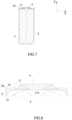
FIG. 1 is a schematic view of a secondary battery according to the present invention. -
FIG. 2 is an exploded view of the secondary battery according to the present invention in which an electrode assembly is not shown. -
FIG. 3 is a schematic view of a cap plate of the secondary battery according to the present invention. -
FIG. 4 is an enlarged view of a part ofFIG. 3 surrounded by a dotted circle. -
FIG. 5 is a cross sectional view of the secondary battery according to the present invention. -
FIG. 6 is an enlarged view of a part ofFIG. 5 surrounded by a dotted circle. -
FIG. 7 is another cross sectional view of the secondary battery according to the present invention. -
FIG. 8 is an enlarged view of a part ofFIG. 7 surrounded by a dotted circle. -
FIG. 9 is a schematic view of an embodiment of the cap plate according to the present invention. -
FIG. 10 is a schematic view of another embodiment of the cap plate according to the present invention. -
FIG. 11 is a schematic view of an opening of a case, in which the opening of the case before assembling with the cap plate is shown by a dotted line, the opening of the case after assembling with the cap plate is shown by a solid line. -
FIG. 12 is a schematic view of the opening of the case according to the present invention in the process of assembling with the cap plate. -
FIG. 13 is another schematic view of the opening of the case according to the present invention in the process of assembling with the cap plate. -
FIG. 14 is a schematic view of a third exterior surface and a fourth exterior surface of the cap plate according to the present invention. - Reference numerals in figures are represented as follows:
- 1 cap plate
- 11 main portion
- 111 first exterior surface
- 112 second exterior surface
- 113 third exterior surface
- 114 groove
- 12 first protruding portion
- 121 fourth exterior surface
- 13 second protruding portion
131 fifth exterior surface - 14 third protruding portion
- 11 main portion
- 2 case
- 21 inner wall
- 22 top surface
- 3 electrode assembly
- 4 electrode terminal
- L1 axis
- L2 first generatrix
- L3 second generatrix
- X transverse direction
- Y longitudinal direction
- Z up-down direction
- Hereinafter a cap plate and a secondary battery according to the present invention will be described in detail in combination with the figures.
- Firstly, a cap plate according to a first aspect of the present invention will be described.
- Referring to
FIGs. 1-14 , acap plate 1 according to the present invention includes amain portion 11 and a first protrudingportion 12. Themain portion 11 includes a firstexterior surface 111, a secondexterior surface 112 and a thirdexterior surface 113 which are formed along a periphery of themain portion 11, the thirdexterior surface 113 is a curved surface and connects the firstexterior surface 111 and the secondexterior surface 112. The first protrudingportion 12 is provided below themain portion 11 and includes a fourthexterior surface 121 extending downwardly from a bottom end of the thirdexterior surface 113, the fourthexterior surface 121 is inclined inwardly relative to the thirdexterior surface 113. - Preferably, the third
exterior surface 113 is a curved surface parallel to an up-down direction Z. Specifically, referring toFIG. 14 , the thirdexterior surface 113 can be generated by a first generatrix L2 rotating around an axis L1, the first generatrix L2 and the axis L1 are parallel to the up-down direction Z. Preferably, the first generatrix L2 rotates around the axis L1 by 90 degrees. The firstexterior surface 111 and the secondexterior surface 112 are planes parallel to the up-down direction Z. Furthermore, the thirdexterior surface 113 is tangential to the firstexterior surface 111 and the secondexterior surface 112. - The
cap plate 1 is a constituent member of a secondary battery. Specifically, thecap plate 1 is used for assembling with acase 2 of the secondary battery. Themain portion 11 of thecap plate 1 can be inserted into an opening of thecase 2 and fixed to aninner wall 21 of thecase 2. When themain portion 11 of thecap plate 1 is inserted into the opening of thecase 2, the thirdexterior surface 113 will be fixed to a corner of theinner wall 21. - A line generated at an intersection of the third
exterior surface 113 and a plane perpendicular to the up-down direction Z is a circular arc, and a radius of the circular arc ranges from 1mm to 10mm. The thirdexterior surface 113 can be formed by providing a rounded corner in themain portion 11. In the forming process of thecase 2, the corner of theinner wall 21 is configured as a rounded corner; in order to ensure sealing performance between thecap plate 1 and thecase 2, the line generated at the intersection of the thirdexterior surface 113 and the plane perpendicular to the up-down direction Z is configured as the circular arc, and the radius of the circular arc is less than or equal to a radius of the rounded corner of theinner wall 21. - When the
main portion 11 of thecap plate 1 is inserted into thecase 2, thecase 2 andmain portion 11 can be welded together by a laser emitted from the outside of thecase 2. In the process of welding thecase 2 andmain portion 11, when the laser moves along the thirdexterior surface 113, a distance between focus of the laser and the thirdexterior surface 113 will change along the circular arc, which will affect welding quality. Because the radius of the circular arc ranges from 1mm to 10mm, variation of the welding quality caused by the distance between focus of the laser and the thirdexterior surface 113 will be little, thereby ensuring sealing performance and strength of the welding zone. - Referring to
FIG. 9, FIG. 10 andFIG. 14 , lengths of lines respectively generated at intersections of the fourthexterior surface 121 and planes perpendicular to the up-down direction Z gradually decrease from top to bottom. In the process of inserting the first protrudingportion 12 into thecase 2, the fourthexterior surface 121 contacts theinner wall 21 of thecase 2; with a downward movement of the first protrudingportion 12, the support force of the first protrudingportion 12 with respect to thecase 2 will increase gradually. Because the lengths of the lines respectively generated at the intersections of the fourthexterior surface 121 and the planes perpendicular to the up-down direction Z gradually decrease from top to bottom, with the downward movement of the first protrudingportion 12, a contacting area between the fourthexterior surface 121 and theinner wall 21 of thecase 2 will increase gradually, thereby preventing deformation of the first protrudingportion 12 caused by the excessive support force. - The lines respectively generated at the intersections of the fourth
exterior surface 121 and the planes perpendicular to the up-down direction Z are circular arcs. Specifically, the fourthexterior surface 121 is generated by a second generatrix L3 rotating around the axis L1, and a top end of the second generatrix L3 is connected with a bottom end of the first generatrix L2. The second generatrix L3 is inclined inwardly relative to the first generatrix L2, in other words, the second generatrix L3 is inclined towards the axis L1, so the fourthexterior surface 121 is inclined inwardly relative to thirdexterior surface 113. An angle between the second generatrix L3 and the axis L1 ranges from 5 degrees to 45 degrees. Similarly, the second generatrix L3 rotates around the axis L1 by 90 degrees. - The
main portion 11 of thecap plate 1 may be a flat plate in shape of quadrilateral. Specifically, referring toFIG. 9 and FIG. 10 , the firstexterior surface 111 is provided as two in number, the secondexterior surface 112 is provided as two in number, the first exterior surfaces 111 and the second exterior surfaces 112 are alternately provided along the periphery of themain portion 11, the thirdexterior surfaces 113 each are provided between each firstexterior surface 111 and each secondexterior surface 112 adjacent to the firstexterior surface 111; each thirdexterior surface 113 is positioned at the corner of themain portion 11, the bottom end of each thirdexterior surface 113 is connected with one corresponding fourthexterior surface 121. In other words, the thirdexterior surface 113 is provided as four in number. The thirdexterior surface 113 may be formed by providing the rounded corner on the flat plate. Because the bottom end of each thirdexterior surface 113 is connected with one corresponding fourthexterior surface 121, the fourthexterior surface 121 is provided as four in number; correspondingly, the first protrudingportion 12 is provided as four in number and respectively formed at four corners of themain portion 11. Preferably, the two first exterior surfaces 111 are perpendicular to a transverse direction X, and the two second exterior surfaces 112 are perpendicular to a longitudinal direction Y. Referring toFIG. 12 andFIG. 13 , the four first protrudingportions 12 respectively apply force to the four corners of theinner wall 21. When a first protrudingportion 12 applies force to a corresponding corner of theinner wall 21, the force can be decomposed into a component F1 and a component F2 in two directions, which in turn can wholly expand the opening of thecase 2 more easily. If the fourthexterior surface 121 of the first protrudingportion 12 applies force to other position of theinner wall 21, direction of the force is single, which will easily lead to the opening of thecase 2 only being partly expanded. Preferably, the number of the first protrudingportions 12 is equal to the number of the corners of theinner wall 21, if the number of the first protrudingportions 12 is less than the number of the corners of theinner wall 21, the opening of thecase 2 will only be partly expanded, which will lead to themain portion 11 of thecap plate 1 being inserted into the opening of thecase 2 difficultly. - Referring to
FIG. 3 and FIG. 4 , thecap plate 1 further includes a second protrudingportion 13 provided below themain portion 11, the second protrudingportion 13 includes a fifthexterior surface 131 extending downwardly from a bottom end of the firstexterior surface 111, the fifthexterior surface 131 is inclined inwardly relative to the firstexterior surface 111. An end of the second protrudingportion 13 in the longitudinal direction Y is connected with the first protrudingportion 12, and the fifthexterior surface 131 of the second protrudingportion 13 is connected with the fourthexterior surface 121 of the first protrudingportion 12. The fifthexterior surface 131 is a plane, a line generated at an intersection of the fifthexterior surface 131 and the fourthexterior surface 121 can be acted as the second generatrix L3. The angle between the second generatrix L3 and the axis L1 is equal to an angle between the fifthexterior surface 131 and the axis L1. Preferably, two ends of the second protrudingportion 13 in the longitudinal direction Y are respectively connected with two first protrudingportions 12, and the fifthexterior surface 131 of the second protrudingportion 13 is connected with the fourth exterior surfaces 121 of the two first protrudingportions 12. A length of the firstexterior surface 111 is smaller than a length of the secondexterior surface 112. Referring toFIG. 11 , in the process of placement of thecase 2 lonely, a long wall of thecase 2 extending in the transverse direction X generally deforms inwardly more than a short wall of thecase 2 extending in the longitudinal direction Y; referring toFIG. 12 , in the process of inserting the first protrudingportion 12 into thecase 2, the long wall of thecase 2 needs to be stretched to a large extent, so a force (which is a reaction with respect to the component F2 shown inFIG. 12 ) in the transverse direction X applied to the first protrudingportion 12 is large; a part of the force in the transverse direction X can be applied to the second protrudingportion 13, which can effectively prevent deformation of the first protrudingportion 12. - Referring to
FIG. 9 , agroove 114 recessed upwardly is provided in a bottom surface of themain portion 11. Thegroove 114 can reduce weight of thecap plate 1, save interior space of the secondary battery, thereby improving energy density. An inner peripheral wall of thegroove 114 can be provided with ribbed plates, which can improve strength of thecap plate 1. Alternatively, referring toFIG. 10 , themain portion 11 also can be a solid structure. - Referring to
FIGs. 2-4 , thecap plate 1 further includes a third protrudingportion 14 provided to themain portion 11 and protruding outwardly. The third protrudingportion 14 extends outwardly from the first exterior surfaces 111, the second exterior surfaces 112 and the third exterior surfaces 113. Preferably, the periphery of themain portion 11 is encircled by the third protrudingportion 14. Alternatively, the third protrudingportion 14 also can only extend outwardly from the first exterior surfaces 111. In the prior art, theinner wall 21 of thecase 2 is generally provided with a step, the step is used to prevent thecap plate 1 being excessively inserted into thecase 2; compared to the step of the prior art, the third protrudingportion 14 provided to the periphery of themain portion 11 not only can prevent thecap plate 1 being excessively inserted into thecase 2, but also further decrease a thickness of thecase 2 and improve the energy density of the secondary battery. - The
cap plate 1 can be made of plastic. Compared to thecap plate 1 made of aluminium alloy, forming method of thecap plate 1 made of the plastic is simple and weight of the plastic is small. - Secondly, a secondary battery according to a second aspect of the present invention will be described.
- Referring to
FIGs. 1-14 , a secondary battery according to the present invention comprises thecap plate 1 according to the first aspect of the present invention and thecase 2. Both thecap plate 1 and thecase 2 are made of plastic, the plastics used for making thecap plate 1 and thecase 2 can be same or different. Thecase 2 includes the opening in a top thereof, a shape of the opening is fitted with a shape of the periphery of themain portion 11; thecap plate 1 is provided to the opening of thecase 2, and themain portion 11 of thecap plate 1 is fixed to theinner wall 21 of thecase 2, the thirdexterior surface 113 is fixed to the corner of theinner wall 21. The first protrudingportion 12 of thecap plate 1 is received in thecase 2, and a gap is provided between the fourthexterior surface 121 of the first protrudingportion 12 and theinner wall 21 of thecase 2, a dimension of the gap increases gradually along a downward direction. - Preferably, the corner of the
inner wall 21 is configured as the rounded corner. - Referring to
FIG. 5 andFIG. 7 , the secondary battery further comprises anelectrode assembly 3 and anelectrode terminal 4, theelectrode assembly 3 is received in thecase 2, theelectrode terminal 4 is fixed to themain portion 11 of thecap plate 1 and electrically connected with theelectrode assembly 3. Theelectrode assembly 3 comprises a positive electrode plate, a negative electrode plate and a separator separating the positive electrode plate and the negative electrode plate. - Because the
case 2 is thin and made of plastic, referring to a dotted line shown inFIG. 11 , the opening of thecase 2 will contract inwardly under the influence of residual stress, which leads to a dimension of the opening being smaller than a dimension of themain portion 11 of thecap plate 1. - In the process of assembling the
case 2 and thecap plate 1, the first protrudingportion 12 needs to be inserted into the corner of theinner wall 21 firstly. Because the fourthexterior surface 121 is inclined inwardly relative to the thirdexterior surface 113, the fourthexterior surface 121 is offset inwardly from top to bottom; even though the opening of thecase 2 contracts, the first protrudingportion 12 also can be inserted into the opening. Referring toFIG. 12 , after inserting the first protrudingportion 12 into the opening, the fourthexterior surface 121 of the first protrudingportion 12 contacts theinner wall 21 of thecase 2; with a downward movement of thecap plate 1, the fourthexterior surface 121 will apply an outward force (such as the component F1 and the component F2 shown inFIG. 12 ) to theinner wall 21 of thecase 2, theinner wall 21 will be stretched outwardly gradually under the influence of the outward force, and the opening of thecase 2 will be expended gradually; referring toFIG. 13 , when the first protrudingportion 12 has been inserted into thecase 2 completely, the opening of thecase 2 can be completely expanded by the first protrudingportion 12, when thecap plate 1 is continuously moved downwardly, themain portion 11 of thecap plate 1 can be allowed to directly insert into the opening. Therefore, the secondary battery of the present invention can reduce difficulty of assembling thecap plate 1 and thecase 2, improve assembling efficiency. - Referring to
FIG. 12 andFIG. 13 , the first protrudingportion 12 is identical with the corner of theinner wall 21 of thecase 2 in number. When the first protrudingportion 12 applies force to the corner of theinner wall 21, the force can be decomposed into the component F1 and the component F2 in two directions, which can wholly expand the opening of thecase 2 more easily. If the fourthexterior surface 121 of the first protrudingportion 12 applies force to other position of theinner wall 21, the direction of the force is single, which will easily lead to the opening of thecase 2 only being partly expanded. In addition, the number of the first protrudingportions 12 needs to be equal to the number of the corners of theinner wall 21, if the number of the first protrudingportions 12 is less than the number of the corners of theinner wall 21, the opening of thecase 2 will be partly expanded, which will lead to themain portion 11 of thecap plate 1 being inserted into the opening of thecase 2 difficultly. The second protrudingportion 13 of thecap plate 1 can improve the strength of the first protrudingportion 12 and help expand the opening of thecase 2. - Preferably, lengths of the lines respectively generated at the intersections of the fourth
exterior surface 121 and the planes perpendicular to the up-down direction Z gradually decrease from top to bottom, so the first protrudingportion 12 can be inserted into thecase 2 easily. Furthermore, in the process of inserting the first protrudingportion 12 into thecase 2, the fourthexterior surface 121 contacts theinner wall 21 of thecase 2; with the downward movement of the first protrudingportion 12, the support force of the first protrudingportion 12 with respect to thecase 2 will increase gradually. Because the lengths of the lines respectively generated at the intersections of the fourthexterior surface 121 and the planes perpendicular to the up-down direction Z gradually decrease from top to bottom, with the downward movement of the first protrudingportion 12, the contacting area between the fourthexterior surface 121 and theinner wall 21 of thecase 2 will increase gradually, thereby preventing deformation of the first protrudingportion 12 caused by the excessive support force. - Preferably, the angle between the second generatrix L3 and the axis L1 ranges from 5 degrees to 45 degrees. If a length of the first protruding
portion 12 extending in the up-down direction Z is constant, with increasing of the angle, the length of the second generatrix L3, an area of the fourthexterior surface 121 and a volume of the first protrudingportion 12 will increase correspondingly; if the angle is larger than 45 degrees, the first protrudingportion 12 will occupy excessive space, which reduces the energy density of the secondary battery. In addition, in the process of assembling thecap plate 1 and thecase 2, if the angle is too large, the first protrudingportion 12 may damage theelectrode assembly 3, thereby leading to short circuit; when thecap plate 1 moves a unit distance downwardly, if the angle is too large, the opening of thecase 2 will deform excessively, which damages thecase 2 easily. In addition, if the angle is too small, the first protrudingportion 12 cannot be easily inserted into the opening of thecase 2, which leads to difficulty of assembling. - Referring to
FIG. 6 andFIG. 8 , the third protrudingportion 14 is attached to atop surface 22 of thecase 2. The third protrudingportion 14 can have a positioning function in the assembling process, prevent themain portion 11 of thecap plate 1 from inserting thecase 2 excessively. - There is an interference fit between the
main portion 11 of thecap plate 1 and theinner wall 21 of thecase 2. The interference fit can ensure that there is no space between themain portion 11 and theinner wall 21 of thecase 2, and improve sealing performance. In addition, the opening of thecase 2 can be expanded by the first protrudingportion 12, so the interference fit will not increase difficulty of assembling. - The first exterior surfaces 111, the second exterior surfaces 112 and the third
exterior surfaces 113 of themain portion 11 of thecap plate 1 can be fixed to theinner wall 21 of thecase 2 by laser welding, and a height of welding zone between themain portion 11 and thecase 2 in the up-down direction Z ranges from 0.5mm to 10 mm. When themain portion 11 is inserted into thecase 2, thecase 2 andmain portion 11 can be welded together by the laser emitted from the outside of thecase 2. For thecap plate 1 made of plastic and thecase 2 made of plastic, the prior art generally melt an edge of thecase 2 and an edge of thecap plate 1 by a hot plate, and then securely connects the edge of thecase 2 and the edge of thecap plate 1 under exterior pressure; however, when the hot plate are separated from thecase 2 or thecap plate 1, the plastic will easily generate filaments due to adhering to the hot plate, and the filaments will enter thecase 2 easily and pierce the separator, which leads to short circuit of theelectrode assembly 3; at the same time, with this connecting way in the prior art, connecting area, connecting strength and sealing performance between thecase 2 and thecap plate 1 are not desirable. The welding way of the present invention will not generate filaments in thecase 2, which can ensure the sealing performance and no foreign matter existing in thecase 2. - The
case 2 is made of plastic and a wall thickness of thecase 2 ranges from 0.1 mm to 0.6mm. The prior art generally securely connects thecase 2 made of metal and thecap plate 1 made of metal by butt welding, in order to ensure welding strength, a gap between thecase 2 andcap plate 1 must be small. In the present invention, thecase 2 is made of plastic and the wall thickness is small, and the opening of thecase 2 will contract inwardly easily under the influence of the residual stress after injection molding, so thecase 2 cannot be attached to thecap plate 1 closely, which may lead to low welding strength or weak welding; in addition, if thecase 2 made of plastic and thecap plate 1 made of plastic are connected by butt welding, it will lead to a small welding area and cannot ensure welding strength. By welding the periphery of themain portion 11 of the cap plate 1 (specifically, the firstexterior surface 111, the secondexterior surface 112 and the third exterior surface 113) to thecase 2 and ensuring that the height of welding zone between the periphery of themain portion 11 of thecap plate 1 and thecase 2 in the up-down direction Z ranges from 0.5mm to 10 mm, it can increase connecting area, prevent low welding strength and weak welding. - Preferably, the
groove 114 recessed upwardly is provided in the bottom surface of themain portion 11. Thegroove 114 can increase interior space of the secondary battery and improves energy density. - The line generated at the intersection of the third
exterior surface 113 and the plane perpendicular to the up-down direction Z is the circular arc, and the radius of the circular arc ranges from 1mm to 10mm. In the process of laser welding, when the laser moves along the thirdexterior surface 113, the distance between the focus of the laser and the thirdexterior surface 113 will change along the circular arc, which leads to the focus of the laser offsetting from the welding zone and variation of welding quality. However, if the radius of the circular arc can be controlled between 1mm and 10mm, the variation of the welding quality caused by the circular arc will not influences the sealing performance and strength of laser welding.
Claims (12)
- A cap plate (1) configured to be comprised by a secondary battery, whereinthe cap plate (1) is rectangular and includes a main portion (11) and a first protruding portion (12);the main portion (11) includes a first exterior surface (111), a second exterior surface (112) and a third exterior surface (113) which are formed along a periphery of the main portion (11), the third exterior surface (113) is a curved surface and connects the first exterior surface (111) and the second exterior surface (112);the first exterior surface (111) is planar and is provided as two in number, the second exterior surface (112) is planar and is provided as two in number, the first exterior surfaces (111) and the second exterior surfaces (112) are alternately provided along the periphery of the main portion (11), the third exterior surfaces (113) is provided as four in number, the third exterior surfaces (113) each are provided between each first exterior surface (111) and each second exterior surface (112) adjacent to the first exterior surface (111), the third exterior surfaces (113) each is positioned at a corner of the cap plate (1);the first protruding portion (12) is provided as four in number and positioned below the main portion (11), and each first protruding portion (12) includes a fourth exterior surface (121) extending downwardly from a bottom end of one corresponding third exterior surface (113), each fourth exterior surface (121) is inclined inwardly relative to the one corresponding third exterior surface (113);the secondary battery further comprises a case (2);the case (2) includes an opening in a top thereof, a shape of the opening is fitted with a shape of the periphery of the main portion (11);the cap plate (1) is provided to the opening of the case (2), and the main portion (11) of the cap plate (1) is fixed to an inner wall (21) of the case (2);the first protruding portion (12) of the cap plate (1) is received in the case (2), and a gap is provided between the fourth exterior surface (121) and the inner wall (21) of the case (2), a dimension of the gap increases gradually along a downward direction;the opening of the case (2) is expanded when the first protruding portion (12) of the cap plate (1) is received in the case (2).
- The cap plate (1) according to Claim 1, wherein
lengths of lines respectively generated at intersections of the fourth exterior surface (121) and planes perpendicular to an up-down direction (Z) gradually decrease from top to bottom. - The cap plate (1) according to Claim 2, wherein the lines are circular arcs.
- The cap plate (1) according to Claim 1, wherein
the fourth exterior surface (121) is generated by a second generatrix (L3) rotating around an axis (L1), and the axis (L1) is parallel to an up-down direction (Z), an angle between the second generatrix (L3) and the axis (L1) ranges from 5 degrees to 45 degrees. - The cap plate (1) according to Claim 1, whereinthe cap plate (1) further includes a second protruding portion (13) provided below the main portion (11), the second protruding portion (13) includes a fifth exterior surface (131) extending downwardly from a bottom end of the first exterior surface (111), the fifth exterior surface (131) is inclined inwardly relative to the first exterior surface (111);an end of the second protruding portion (13) in a longitudinal direction (Y) is connected with the first protruding portion (12), and the fifth exterior surface (131) of the second protruding portion (13) is connected with the fourth exterior surface (121) of the first protruding portion (12).
- The cap plate (1) according to Claim 1, wherein a groove (114) recessed upwardly is provided in a bottom surface of the main portion (11).
- The cap plate (1) according to Claim 1, wherein
a line generated at an intersection of the third exterior surface (113) and a plane perpendicular to an up-down direction (Z) is a circular arc, and a radius of the circular arc ranges from 1mm to 10mm. - A secondary battery, whereinthe secondary battery comprises the cap plate (1) according to any one of Claims 1-7 and a case (2);the case (2) includes an opening in a top thereof, a shape of the opening is fitted with a shape of the periphery of the main portion (11);the cap plate (1) is provided to the opening of the case (2), and the main portion (11) of the cap plate (1) is fixed to an inner wall (21) of the case (2);the first protruding portion (12) of the cap plate (1) is received in the case (2), and a gap is provided between the fourth exterior surface (121) and the inner wall (21) of the case (2), a dimension of the gap increases gradually along a downward direction;the opening of the case (2) is expanded when the first protruding portion (12) of the cap plate (1) is received in the case (2).
- The secondary battery according to Claim 8, wherein
the cap plate (1) further includes a third protruding portion (14) provided to the main portion (11) and protruding outwardly, and the third protruding portion (14) is attached to a top surface (22) of the case (2). - The secondary battery according to Claim 8, wherein there is an interference fit between the main portion (11) of the cap plate (1) and the inner wall (21) of the case (2).
- The secondary battery according to Claim 8, wherein
the first exterior surfaces (111), the second exterior surfaces (112) and the third exterior surfaces (113) of the main portion (11) of the cap plate (1) are fixed to the inner wall (21) of the case (2) by laser welding, and a height of welding zone between the main portion (11) and the case (2) in an up-down direction (Z) ranges from 0.5mm to 10 mm. - The secondary battery according to Claim 8, wherein the case (2) is made of plastic and a wall thickness of the case (2) ranges from 0.1 mm to 0.6mm.
Applications Claiming Priority (1)
| Application Number | Priority Date | Filing Date | Title |
|---|---|---|---|
| CN201820170296.5U CN207818650U (en) | 2018-01-31 | 2018-01-31 | Top cover and secondary battery |
Publications (3)
| Publication Number | Publication Date |
|---|---|
| EP3522251A1 EP3522251A1 (en) | 2019-08-07 |
| EP3522251C0 EP3522251C0 (en) | 2025-05-07 |
| EP3522251B1 true EP3522251B1 (en) | 2025-05-07 |
Family
ID=62116257
Family Applications (1)
| Application Number | Title | Priority Date | Filing Date |
|---|---|---|---|
| EP18170610.2A Active EP3522251B1 (en) | 2018-01-31 | 2018-05-03 | Cap plate and secondary battery |
Country Status (4)
| Country | Link |
|---|---|
| US (1) | US11196115B2 (en) |
| EP (1) | EP3522251B1 (en) |
| JP (1) | JP6606569B2 (en) |
| CN (1) | CN207818650U (en) |
Families Citing this family (9)
| Publication number | Priority date | Publication date | Assignee | Title |
|---|---|---|---|---|
| CN113228384A (en) * | 2018-12-28 | 2021-08-06 | 松下知识产权经营株式会社 | Battery and method for manufacturing same |
| CN110148686B (en) * | 2019-05-10 | 2025-12-02 | 欣旺达动力科技股份有限公司 | A power battery top cover and a secondary battery |
| CN210668432U (en) * | 2019-10-10 | 2020-06-02 | 宁德新能源科技有限公司 | Shell and battery with same |
| WO2022036531A1 (en) | 2020-08-17 | 2022-02-24 | 宁德时代新能源科技股份有限公司 | Battery cell, battery, and method and apparatus for preparing battery cell |
| CN215070147U (en) * | 2021-06-29 | 2021-12-07 | 比亚迪股份有限公司 | Battery case and battery |
| CN216750092U (en) * | 2022-01-27 | 2022-06-14 | 宁德时代新能源科技股份有限公司 | Battery cells, batteries and electrical devices |
| CN114614173A (en) * | 2022-03-30 | 2022-06-10 | 安徽力翔电池科技有限公司 | High-strength microcrystal integrated safety top cover structure |
| EP4601091A4 (en) * | 2023-12-27 | 2025-12-31 | Eve Power Co Ltd | BATTERY HOUSING |
| CN222126784U (en) * | 2023-12-27 | 2024-12-06 | 湖北亿纬动力有限公司 | Battery box |
Family Cites Families (19)
| Publication number | Priority date | Publication date | Assignee | Title |
|---|---|---|---|---|
| DE2544244A1 (en) * | 1975-10-03 | 1977-04-14 | Mauser Kg | PLASTIC CONTAINER WITH SEALABLE LID |
| JPS55141073A (en) * | 1979-04-19 | 1980-11-04 | Matsushita Electric Ind Co Ltd | Manufacture of storage battery |
| JPH1186809A (en) * | 1997-09-08 | 1999-03-30 | Showa Alum Corp | Container joining method |
| US6001504A (en) * | 1998-03-11 | 1999-12-14 | Duracell Inc. | Prismatic battery housing |
| JP2001084973A (en) * | 1999-09-17 | 2001-03-30 | Toshiba Corp | Sealed battery and method of manufacturing the same |
| US6461765B1 (en) * | 2000-02-14 | 2002-10-08 | Aer Energy Resources Inc. | Metal-air cell housing with improved peripheral seal design |
| DE10146957A1 (en) * | 2001-09-24 | 2003-04-17 | Nbt Gmbh | Tightly sealed accumulator |
| JP2008311193A (en) * | 2007-06-18 | 2008-12-25 | Toyota Motor Corp | Battery and manufacturing method thereof |
| JP2013258063A (en) * | 2012-06-13 | 2013-12-26 | Komatsu Ltd | Power storage device |
| CN106887536B (en) * | 2012-08-31 | 2020-01-10 | 日立汽车系统株式会社 | Square secondary battery |
| CN203377273U (en) | 2013-07-25 | 2014-01-01 | 中航锂电(洛阳)有限公司 | Lithium battery shell |
| US20150053683A1 (en) * | 2013-08-23 | 2015-02-26 | Becklin Holdings, Inc. | Closure system for containers |
| JP5979607B2 (en) * | 2013-11-20 | 2016-08-24 | Smk株式会社 | Manufacturing method of sealed battery |
| JP6331753B2 (en) * | 2014-06-24 | 2018-05-30 | 株式会社豊田自動織機 | Battery case |
| JP2015111573A (en) * | 2014-12-22 | 2015-06-18 | トヨタ自動車株式会社 | Battery and manufacturing method thereof |
| KR102361706B1 (en) * | 2015-03-02 | 2022-02-09 | 삼성에스디아이 주식회사 | Rechargeable battery |
| KR102385747B1 (en) | 2015-09-17 | 2022-04-11 | 삼성에스디아이 주식회사 | Rechargeable battery |
| JP2017076464A (en) * | 2015-10-13 | 2017-04-20 | トヨタ自動車株式会社 | Secondary battery |
| CN206210851U (en) | 2016-10-31 | 2017-05-31 | 深圳市迪凯能科技有限公司 | For the hard plastic shell of lithium battery |
-
2018
- 2018-01-31 CN CN201820170296.5U patent/CN207818650U/en active Active
- 2018-03-22 JP JP2018054916A patent/JP6606569B2/en active Active
- 2018-05-03 EP EP18170610.2A patent/EP3522251B1/en active Active
- 2018-05-10 US US15/976,638 patent/US11196115B2/en active Active
Also Published As
| Publication number | Publication date |
|---|---|
| EP3522251A1 (en) | 2019-08-07 |
| EP3522251C0 (en) | 2025-05-07 |
| JP2019133905A (en) | 2019-08-08 |
| US11196115B2 (en) | 2021-12-07 |
| CN207818650U (en) | 2018-09-04 |
| JP6606569B2 (en) | 2019-11-13 |
| US20190237712A1 (en) | 2019-08-01 |
Similar Documents
| Publication | Publication Date | Title |
|---|---|---|
| EP3522251B1 (en) | Cap plate and secondary battery | |
| US11929521B2 (en) | Rechargeable battery | |
| JP4530333B2 (en) | Sealed battery | |
| WO2020088239A1 (en) | Top pressing plate, secondary battery and manufacturing method for secondary battery | |
| US20250023146A1 (en) | Battery casing and battery | |
| CN212571138U (en) | Single battery and power battery | |
| US20210242521A1 (en) | Secondary battery | |
| KR20130115594A (en) | Rechargeable battery | |
| US9160029B2 (en) | Secondary battery including a can having first and second stepped portions having different depths | |
| EP3474342A1 (en) | Battery cap assembly and secondary battery | |
| EP3246930B1 (en) | Electric energy storage device having improved terminal structure | |
| KR102752722B1 (en) | Cap Assembly and Cylindrical Secondary Battery Comprising the Same | |
| KR102806743B1 (en) | Cylindrical Secondary Battery Comprising Positive Electrode Tab Fastening Member | |
| US20240304912A1 (en) | Battery | |
| KR100855182B1 (en) | Cylindrical battery with top cap coupled by welding | |
| KR102320014B1 (en) | Secondary battery and method of manufacturing the same | |
| KR102835533B1 (en) | Secondary battery and battery pack comprising the same | |
| JP3599391B2 (en) | Method of manufacturing prismatic battery | |
| CN223927494U (en) | Shell, battery cell and battery | |
| CN222395007U (en) | A pole ear and pole connector and battery | |
| CN219267835U (en) | Batteries and battery devices | |
| US20250132429A1 (en) | Battery with no roll groove | |
| WO2025189858A1 (en) | Cap structure and battery | |
| EP4661167A1 (en) | Secondary battery | |
| US20230395912A1 (en) | Pouch Type Secondary Battery, Battery Pack, and Method for Manufacturing Pouch Type Secondary Battery |
Legal Events
| Date | Code | Title | Description |
|---|---|---|---|
| PUAI | Public reference made under article 153(3) epc to a published international application that has entered the european phase |
Free format text: ORIGINAL CODE: 0009012 |
|
| STAA | Information on the status of an ep patent application or granted ep patent |
Free format text: STATUS: REQUEST FOR EXAMINATION WAS MADE |
|
| 17P | Request for examination filed |
Effective date: 20180503 |
|
| AK | Designated contracting states |
Kind code of ref document: A1 Designated state(s): AL AT BE BG CH CY CZ DE DK EE ES FI FR GB GR HR HU IE IS IT LI LT LU LV MC MK MT NL NO PL PT RO RS SE SI SK SM TR |
|
| AX | Request for extension of the european patent |
Extension state: BA ME |
|
| STAA | Information on the status of an ep patent application or granted ep patent |
Free format text: STATUS: EXAMINATION IS IN PROGRESS |
|
| 17Q | First examination report despatched |
Effective date: 20220720 |
|
| RAP1 | Party data changed (applicant data changed or rights of an application transferred) |
Owner name: CONTEMPORARY AMPEREX TECHNOLOGY(HONG KONG) LIMITED |
|
| REG | Reference to a national code |
Ref country code: DE Ref legal event code: R079 Free format text: PREVIOUS MAIN CLASS: H01M0002040000 Ipc: H01M0050103000 Ref country code: DE Ref legal event code: R079 Ref document number: 602018081671 Country of ref document: DE Free format text: PREVIOUS MAIN CLASS: H01M0002040000 Ipc: H01M0050103000 |
|
| GRAP | Despatch of communication of intention to grant a patent |
Free format text: ORIGINAL CODE: EPIDOSNIGR1 |
|
| STAA | Information on the status of an ep patent application or granted ep patent |
Free format text: STATUS: GRANT OF PATENT IS INTENDED |
|
| RIC1 | Information provided on ipc code assigned before grant |
Ipc: H01M 50/169 20210101ALI20250107BHEP Ipc: H01M 50/15 20210101ALI20250107BHEP Ipc: H01M 50/148 20210101ALI20250107BHEP Ipc: H01M 50/103 20210101AFI20250107BHEP |
|
| INTG | Intention to grant announced |
Effective date: 20250115 |
|
| GRAS | Grant fee paid |
Free format text: ORIGINAL CODE: EPIDOSNIGR3 |
|
| GRAA | (expected) grant |
Free format text: ORIGINAL CODE: 0009210 |
|
| STAA | Information on the status of an ep patent application or granted ep patent |
Free format text: STATUS: THE PATENT HAS BEEN GRANTED |
|
| AK | Designated contracting states |
Kind code of ref document: B1 Designated state(s): AL AT BE BG CH CY CZ DE DK EE ES FI FR GB GR HR HU IE IS IT LI LT LU LV MC MK MT NL NO PL PT RO RS SE SI SK SM TR |
|
| REG | Reference to a national code |
Ref country code: GB Ref legal event code: FG4D |
|
| REG | Reference to a national code |
Ref country code: CH Ref legal event code: EP |
|
| REG | Reference to a national code |
Ref country code: DE Ref legal event code: R096 Ref document number: 602018081671 Country of ref document: DE |
|
| REG | Reference to a national code |
Ref country code: IE Ref legal event code: FG4D |
|
| U01 | Request for unitary effect filed |
Effective date: 20250530 |
|
| U07 | Unitary effect registered |
Designated state(s): AT BE BG DE DK EE FI FR IT LT LU LV MT NL PT RO SE SI Effective date: 20250610 |
|
| PG25 | Lapsed in a contracting state [announced via postgrant information from national office to epo] |
Ref country code: ES Free format text: LAPSE BECAUSE OF FAILURE TO SUBMIT A TRANSLATION OF THE DESCRIPTION OR TO PAY THE FEE WITHIN THE PRESCRIBED TIME-LIMIT Effective date: 20250507 |
|
| PG25 | Lapsed in a contracting state [announced via postgrant information from national office to epo] |
Ref country code: NO Free format text: LAPSE BECAUSE OF FAILURE TO SUBMIT A TRANSLATION OF THE DESCRIPTION OR TO PAY THE FEE WITHIN THE PRESCRIBED TIME-LIMIT Effective date: 20250807 Ref country code: GR Free format text: LAPSE BECAUSE OF FAILURE TO SUBMIT A TRANSLATION OF THE DESCRIPTION OR TO PAY THE FEE WITHIN THE PRESCRIBED TIME-LIMIT Effective date: 20250808 |
|
| PG25 | Lapsed in a contracting state [announced via postgrant information from national office to epo] |
Ref country code: PL Free format text: LAPSE BECAUSE OF FAILURE TO SUBMIT A TRANSLATION OF THE DESCRIPTION OR TO PAY THE FEE WITHIN THE PRESCRIBED TIME-LIMIT Effective date: 20250507 |
|
| PG25 | Lapsed in a contracting state [announced via postgrant information from national office to epo] |
Ref country code: HR Free format text: LAPSE BECAUSE OF FAILURE TO SUBMIT A TRANSLATION OF THE DESCRIPTION OR TO PAY THE FEE WITHIN THE PRESCRIBED TIME-LIMIT Effective date: 20250507 |
|
| PG25 | Lapsed in a contracting state [announced via postgrant information from national office to epo] |
Ref country code: RS Free format text: LAPSE BECAUSE OF FAILURE TO SUBMIT A TRANSLATION OF THE DESCRIPTION OR TO PAY THE FEE WITHIN THE PRESCRIBED TIME-LIMIT Effective date: 20250807 |
|
| PG25 | Lapsed in a contracting state [announced via postgrant information from national office to epo] |
Ref country code: IS Free format text: LAPSE BECAUSE OF FAILURE TO SUBMIT A TRANSLATION OF THE DESCRIPTION OR TO PAY THE FEE WITHIN THE PRESCRIBED TIME-LIMIT Effective date: 20250907 |
|
| PG25 | Lapsed in a contracting state [announced via postgrant information from national office to epo] |
Ref country code: SM Free format text: LAPSE BECAUSE OF FAILURE TO SUBMIT A TRANSLATION OF THE DESCRIPTION OR TO PAY THE FEE WITHIN THE PRESCRIBED TIME-LIMIT Effective date: 20250507 |
|
| PG25 | Lapsed in a contracting state [announced via postgrant information from national office to epo] |
Ref country code: CZ Free format text: LAPSE BECAUSE OF FAILURE TO SUBMIT A TRANSLATION OF THE DESCRIPTION OR TO PAY THE FEE WITHIN THE PRESCRIBED TIME-LIMIT Effective date: 20250507 |
|
| PG25 | Lapsed in a contracting state [announced via postgrant information from national office to epo] |
Ref country code: SK Free format text: LAPSE BECAUSE OF FAILURE TO SUBMIT A TRANSLATION OF THE DESCRIPTION OR TO PAY THE FEE WITHIN THE PRESCRIBED TIME-LIMIT Effective date: 20250507 |
|
| PLBE | No opposition filed within time limit |
Free format text: ORIGINAL CODE: 0009261 |
|
| STAA | Information on the status of an ep patent application or granted ep patent |
Free format text: STATUS: NO OPPOSITION FILED WITHIN TIME LIMIT |
|
| REG | Reference to a national code |
Ref country code: CH Ref legal event code: L10 Free format text: ST27 STATUS EVENT CODE: U-0-0-L10-L00 (AS PROVIDED BY THE NATIONAL OFFICE) Effective date: 20260318 |
|
| PGFP | Annual fee paid to national office [announced via postgrant information from national office to epo] |
Ref country code: GB Payment date: 20260331 Year of fee payment: 9 |
|
| 26N | No opposition filed |
Effective date: 20260210 |