EP3522184A1 - Contactless power feeding coil unit - Google Patents
Contactless power feeding coil unit Download PDFInfo
- Publication number
- EP3522184A1 EP3522184A1 EP17856068.6A EP17856068A EP3522184A1 EP 3522184 A1 EP3522184 A1 EP 3522184A1 EP 17856068 A EP17856068 A EP 17856068A EP 3522184 A1 EP3522184 A1 EP 3522184A1
- Authority
- EP
- European Patent Office
- Prior art keywords
- radial
- coils
- coil
- power supply
- cylindrical
- Prior art date
- Legal status (The legal status is an assumption and is not a legal conclusion. Google has not performed a legal analysis and makes no representation as to the accuracy of the status listed.)
- Withdrawn
Links
Images




Classifications
-
- H—ELECTRICITY
- H02—GENERATION; CONVERSION OR DISTRIBUTION OF ELECTRIC POWER
- H02J—ELECTRIC POWER NETWORKS; CIRCUIT ARRANGEMENTS OR SYSTEMS FOR SUPPLYING OR DISTRIBUTING ELECTRIC POWER; SYSTEMS FOR STORING ELECTRIC ENERGY
- H02J50/00—Circuit arrangements or systems for wireless supply or distribution of electric power
- H02J50/005—Mechanical details of housing or structure aiming to accommodate the power transfer means, e.g. mechanical integration of coils, antennas or transducers into emitting or receiving devices
-
- B—PERFORMING OPERATIONS; TRANSPORTING
- B60—VEHICLES IN GENERAL
- B60L—PROPULSION OF ELECTRICALLY-PROPELLED VEHICLES; SUPPLYING ELECTRIC POWER FOR AUXILIARY EQUIPMENT OF ELECTRICALLY-PROPELLED VEHICLES; ELECTRODYNAMIC BRAKE SYSTEMS FOR VEHICLES IN GENERAL; MAGNETIC SUSPENSION OR LEVITATION FOR VEHICLES; MONITORING OPERATING VARIABLES OF ELECTRICALLY-PROPELLED VEHICLES; ELECTRIC SAFETY DEVICES FOR ELECTRICALLY-PROPELLED VEHICLES
- B60L53/00—Methods of charging batteries, specially adapted for electric vehicles; Charging stations or on-board charging equipment therefor; Exchange of energy storage elements in electric vehicles
- B60L53/10—Methods of charging batteries, specially adapted for electric vehicles; Charging stations or on-board charging equipment therefor; Exchange of energy storage elements in electric vehicles characterised by the energy transfer between the charging station and the vehicle
- B60L53/12—Inductive energy transfer
-
- H—ELECTRICITY
- H01—ELECTRIC ELEMENTS
- H01F—MAGNETS; INDUCTANCES; TRANSFORMERS; SELECTION OF MATERIALS FOR THEIR MAGNETIC PROPERTIES
- H01F27/00—Details of transformers or inductances, in general
- H01F27/28—Coils; Windings; Conductive connections
-
- H—ELECTRICITY
- H01—ELECTRIC ELEMENTS
- H01F—MAGNETS; INDUCTANCES; TRANSFORMERS; SELECTION OF MATERIALS FOR THEIR MAGNETIC PROPERTIES
- H01F27/00—Details of transformers or inductances, in general
- H01F27/28—Coils; Windings; Conductive connections
- H01F27/2804—Printed windings
-
- H—ELECTRICITY
- H01—ELECTRIC ELEMENTS
- H01F—MAGNETS; INDUCTANCES; TRANSFORMERS; SELECTION OF MATERIALS FOR THEIR MAGNETIC PROPERTIES
- H01F27/00—Details of transformers or inductances, in general
- H01F27/28—Coils; Windings; Conductive connections
- H01F27/2823—Wires
-
- H—ELECTRICITY
- H01—ELECTRIC ELEMENTS
- H01F—MAGNETS; INDUCTANCES; TRANSFORMERS; SELECTION OF MATERIALS FOR THEIR MAGNETIC PROPERTIES
- H01F38/00—Adaptations of transformers or inductances for specific applications or functions
- H01F38/14—Inductive couplings
-
- H—ELECTRICITY
- H01—ELECTRIC ELEMENTS
- H01F—MAGNETS; INDUCTANCES; TRANSFORMERS; SELECTION OF MATERIALS FOR THEIR MAGNETIC PROPERTIES
- H01F5/00—Coils
- H01F5/02—Coils wound on non-magnetic supports, e.g. formers
-
- H—ELECTRICITY
- H02—GENERATION; CONVERSION OR DISTRIBUTION OF ELECTRIC POWER
- H02J—ELECTRIC POWER NETWORKS; CIRCUIT ARRANGEMENTS OR SYSTEMS FOR SUPPLYING OR DISTRIBUTING ELECTRIC POWER; SYSTEMS FOR STORING ELECTRIC ENERGY
- H02J50/00—Circuit arrangements or systems for wireless supply or distribution of electric power
- H02J50/10—Circuit arrangements or systems for wireless supply or distribution of electric power using inductive coupling
-
- H—ELECTRICITY
- H02—GENERATION; CONVERSION OR DISTRIBUTION OF ELECTRIC POWER
- H02J—ELECTRIC POWER NETWORKS; CIRCUIT ARRANGEMENTS OR SYSTEMS FOR SUPPLYING OR DISTRIBUTING ELECTRIC POWER; SYSTEMS FOR STORING ELECTRIC ENERGY
- H02J50/00—Circuit arrangements or systems for wireless supply or distribution of electric power
- H02J50/40—Circuit arrangements or systems for wireless supply or distribution of electric power using two or more transmitting or receiving devices
- H02J50/402—Circuit arrangements or systems for wireless supply or distribution of electric power using two or more transmitting or receiving devices the two or more transmitting or the two or more receiving devices being integrated in the same unit, e.g. power mats with several coils or antennas with several sub-antennas
-
- B—PERFORMING OPERATIONS; TRANSPORTING
- B60—VEHICLES IN GENERAL
- B60M—POWER SUPPLY LINES, AND DEVICES ALONG RAILS, FOR ELECTRICALLY- PROPELLED VEHICLES
- B60M7/00—Power lines or rails specially adapted for electrically-propelled vehicles of special types, e.g. suspension tramway, ropeway, underground railway
-
- H—ELECTRICITY
- H01—ELECTRIC ELEMENTS
- H01F—MAGNETS; INDUCTANCES; TRANSFORMERS; SELECTION OF MATERIALS FOR THEIR MAGNETIC PROPERTIES
- H01F27/00—Details of transformers or inductances, in general
- H01F27/28—Coils; Windings; Conductive connections
- H01F27/2804—Printed windings
- H01F2027/2809—Printed windings on stacked layers
-
- H—ELECTRICITY
- H01—ELECTRIC ELEMENTS
- H01F—MAGNETS; INDUCTANCES; TRANSFORMERS; SELECTION OF MATERIALS FOR THEIR MAGNETIC PROPERTIES
- H01F27/00—Details of transformers or inductances, in general
- H01F27/28—Coils; Windings; Conductive connections
- H01F27/32—Insulating of coils, windings, or parts thereof
- H01F27/324—Insulation between coil and core, between different winding sections, around the coil; Other insulation structures
- H01F27/325—Coil bobbins
-
- Y—GENERAL TAGGING OF NEW TECHNOLOGICAL DEVELOPMENTS; GENERAL TAGGING OF CROSS-SECTIONAL TECHNOLOGIES SPANNING OVER SEVERAL SECTIONS OF THE IPC; TECHNICAL SUBJECTS COVERED BY FORMER USPC CROSS-REFERENCE ART COLLECTIONS [XRACs] AND DIGESTS
- Y02—TECHNOLOGIES OR APPLICATIONS FOR MITIGATION OR ADAPTATION AGAINST CLIMATE CHANGE
- Y02T—CLIMATE CHANGE MITIGATION TECHNOLOGIES RELATED TO TRANSPORTATION
- Y02T10/00—Road transport of goods or passengers
- Y02T10/60—Other road transportation technologies with climate change mitigation effect
- Y02T10/70—Energy storage systems for electromobility, e.g. batteries
-
- Y—GENERAL TAGGING OF NEW TECHNOLOGICAL DEVELOPMENTS; GENERAL TAGGING OF CROSS-SECTIONAL TECHNOLOGIES SPANNING OVER SEVERAL SECTIONS OF THE IPC; TECHNICAL SUBJECTS COVERED BY FORMER USPC CROSS-REFERENCE ART COLLECTIONS [XRACs] AND DIGESTS
- Y02—TECHNOLOGIES OR APPLICATIONS FOR MITIGATION OR ADAPTATION AGAINST CLIMATE CHANGE
- Y02T—CLIMATE CHANGE MITIGATION TECHNOLOGIES RELATED TO TRANSPORTATION
- Y02T10/00—Road transport of goods or passengers
- Y02T10/60—Other road transportation technologies with climate change mitigation effect
- Y02T10/7072—Electromobility specific charging systems or methods for batteries, ultracapacitors, supercapacitors or double-layer capacitors
-
- Y—GENERAL TAGGING OF NEW TECHNOLOGICAL DEVELOPMENTS; GENERAL TAGGING OF CROSS-SECTIONAL TECHNOLOGIES SPANNING OVER SEVERAL SECTIONS OF THE IPC; TECHNICAL SUBJECTS COVERED BY FORMER USPC CROSS-REFERENCE ART COLLECTIONS [XRACs] AND DIGESTS
- Y02—TECHNOLOGIES OR APPLICATIONS FOR MITIGATION OR ADAPTATION AGAINST CLIMATE CHANGE
- Y02T—CLIMATE CHANGE MITIGATION TECHNOLOGIES RELATED TO TRANSPORTATION
- Y02T90/00—Enabling technologies or technologies with a potential or indirect contribution to GHG emissions mitigation
- Y02T90/10—Technologies relating to charging of electric vehicles
- Y02T90/14—Plug-in electric vehicles
Definitions
- the present invention relates to a contactless power supply coil unit.
- PTL 1 discloses a structure in which a plurality of substrates, which have spiral-shaped grooves in which coil conductors are arranged, are stacked on each other in multiple layers.
- coils may be stacked in multiple layers in a radial direction.
- the inner diameters of the coils increase as the coils are wound toward the radial-direction outer side, the inductance and resistance of the coils are increased. Therefore, the potential difference between the coils disposed on the radial-direction outer side becomes large and a discharge phenomenon is likely to occur. Therefore, there is a problem in that it is not possible to increase the number of coils connected in series, and the amount of electric power that can be transmitted by the wireless power supply device cannot be increased.
- an object of the present invention is to provide a contactless power supply coil unit having a structure capable of suppressing the occurrence of a discharge phenomenon.
- a contactless power supply coil unit includes a plurality of coils wound around a predetermined center axis and a holding member that holds the plurality of coils.
- the plurality of coils are disposed at intervals so as to overlap each other in a radial direction and form respective annular layers stacked in a radial direction.
- the coils forming the layers that are adjacent to each other are connected in series to each other. The intervals between the layers that are adjacent to each other increase as the intervals are located progressively toward a radial-direction outer side.
- a contactless power supply coil unit having a structure capable of suppressing the occurrence of a discharge phenomenon.
- a contactless power supply coil unit 10 of the present embodiment includes a plurality of coils 50 wound around a predetermined center axis J, and a holding member 20 that holds the plurality of coils 50.
- the center axis J extends in the up down direction.
- axial direction a direction parallel to the center axis J
- radial direction a radial direction with the center axis J as the center
- radial direction a circumferential direction with the center axis J as the center
- circumferential direction with the center axis J as the center will be simply referred to as "circumferential direction”.
- the lower side in the axial direction in Fig. 1 will be simply referred to as "lower side”.
- the lower side corresponds to one axial-direction side.
- the upper side corresponds to the other axial-direction side.
- the upper side and the lower side are simply terms for explaining the relative positional relationship between the respective parts and do not limit the actual arrangement relationship or the like.
- the Z-axis direction is a direction parallel to the center axis J, that is, the axial direction.
- the X-axis direction is a direction perpendicular to the Z-axis direction and is a direction parallel to the long-side direction of the contactless power supply coil unit 10.
- the X-axis direction is a direction perpendicular to both the Z-axis direction and the Y-axis direction and is a direction parallel to the short-side direction of the contactless power supply coil unit 10.
- the direction parallel to the Y-axis direction will be simply referred to as “long-side direction”, and the direction parallel to the X-axis direction will be simply referred to as “short-side direction”. Further, the coils 50 are not illustrated in Fig. 1 .
- the plurality of coils 50 are disposed at intervals so as to overlap each other in the radial direction and form respective annular layers F stacked in the radial direction.
- the coils 50 of the present embodiment are, for example, provided as five coils, a first coil 51 to a fifth coil 55. Five layers F formed by the first coil 51 to the fifth coil 55, namely, a first layer F1 to a fifth layer F5, are provided.
- the first coil 51 forms the first layer F1.
- a second coil 52 forms a second layer F2.
- a third coil 53 forms a third layer F3.
- a fourth coil 54 forms a fourth layer F4.
- the fifth coil 55 forms the fifth layer F5.
- the first coil 51, the second coil 52, the third coil 53, the fourth coil 54, and the fifth coil 55 are disposed in this order from a radial-direction inner side to a radial-direction outer side.
- each of the coils 50 and each of the layers F are rectangular annular shapes elongated in the long-side direction in plan view.
- the second coil 52 and the second layer F2 are disposed on the radial-direction outer side of the first coil 51 and the first layer F1 and surround the first coil 51 and the first layer F1.
- the third coil 53 and the third layer F3 are disposed on the radial-direction outer side of the second coil 52 and the second layer F2 and surround the second coil 52 and the second layer F2.
- the fourth coil 54 and the fourth layer F4 are disposed on the radial-direction outer side of the third coil 53 and the third layer F3 and surround the third coil 53 and the third layer F3.
- the fifth coil 55 and the fifth layer F5 are disposed on the radial-direction outer side of the fourth coil 54 and the fourth layer F4 and surround the fourth coil 54 and the fourth layer F4.
- the inner diameters of the coils 50 become respectively larger as the coils 50 are located progressively toward the radial-direction outer side. That is, the inner diameter of the second coil 52 is larger than the inner diameter of the first coil 51.
- the inner diameter of the third coil 53 is larger than the inner diameter of the second coil 52.
- the inner diameter of the fourth coil 54 is larger than the inner diameter of the third coil 53.
- the inner diameter of the fifth coil 55 is larger than the inner diameter of the fourth coil 54.
- the coils 50 forming the layers F that are adjacent to each other are connected to each other in series. That is, in the present embodiment, the five coils 50 are connected in series in the radial direction. Each of the coils 50 has an inductance L and a resistance R. Although not illustrated, the five coils 50 connected in series are connected to a capacitor and an AC power source, and form an RLC series resonance circuit.
- the contactless power supply coil unit 10 of the present embodiment is used, for example, in a magnetic-field-resonance type contactless power supply device.
- the inductance L and the resistance R of the third coil 53 are larger than the inductance L and the resistance R of the second coil 52.
- the inductance L and the resistance R of the fourth coil 54 are larger than the inductance L and the resistance R of the third coil 53.
- the inductance L and the resistance R of the fifth coil 55 are larger than the inductance L and the resistance R of the fourth coil 54.
- an interval D1 between the first layer F1 and the second layer F2 is the interval between a radial-direction-outer-side surface of the first coil 51 and a radial-direction-inner-side surface of the second coil 52.
- An interval D2 between the second layer F2 and the third layer F3 is the interval between a radial-direction-outer-side surface of the second coil 52 and a radial-direction-inner-side surface of the third coil 53.
- An interval D3 between the third layer F3 and the fourth layer F4 is the interval between a radial-direction-outer-side surface of the third coil 53 and a radial-direction-inner-side surface of the fourth coil 54.
- An interval D4 between the fourth layer F4 and the fifth layer F5 is the interval between a radial-direction-outer-side surface of the fourth coil 54 and a radial-direction-inner-side surface of the fifth coil 55.
- the intervals D1 to D4 are substantially uniform over the entire circumferential direction.
- the intervals D1 to D4 of the layers F that are adjacent to each other increase as the intervals are located progressively toward the radial-direction outer side.
- the interval D2 is larger than the interval D1.
- the interval D3 is larger than the interval D2.
- the interval D4 is larger than the interval D3. That is, the magnitudes of the intervals D1 to D4 are D1 ⁇ D2 ⁇ D3 ⁇ D4.
- a potential difference V1 between the winding start of the first coil 51 and the winding end of the second coil 52 illustrated in Fig. 4 is the sum of the value of the voltage applied to the first coil 51 and the value of the voltage applied to the second coil 52.
- a potential difference V2 between the winding start of the second coil 52 and the winding end of the third coil 53 is the sum of the value of the voltage applied to the second coil 52 and the value of the voltage applied to the third coil 53.
- a potential difference V3 between the winding start of the third coil 53 and the winding end of the fourth coil 54 is the sum of the value of the voltage applied to the third coil 53 and the value of the voltage applied to the fourth coil 54.
- a potential difference V4 between the winding start of the fourth coil 54 and the winding end of the fifth coil 55 is the sum of the value of the voltage applied to the fourth coil 54 and the value of the voltage applied to the fifth coil 55.
- the voltages applied to the coils 50 increase as the coils 50 are located progressively toward the radial-direction outer side. Therefore, the potential difference V1, the potential difference V2, the potential difference V3, and the potential difference V4 increase in this order. As a result, a discharge phenomenon is more likely to occur between the coils 50 positioned on the radial-direction outer side.
- the coils 50 because the intervals between the coils 50 increase as the coils are located progressively toward the radial-direction outer side, the coils 50 can be disposed further apart as the potential difference increases. Therefore, the occurrence of a discharge phenomenon can be suppressed.
- the number of the coils 50 connected in series can be increased and the voltage that can be applied to each of the coils 50 can also be increased. Therefore, it is possible to increase the amount of electric power that can be transmitted by the contactless power supply device in which the contactless power supply coil unit 10 is mounted.
- the holding member 20 includes a core member 30, a plurality of cylindrical members 40, and a core 60.
- the core member 30 is disposed along the center axis J.
- the core member 30 has a substantially rectangular parallelepiped shape that is elongated in the long-side direction.
- the plurality of cylindrical members 40 are disposed at intervals on the radial-direction outer side of the core member 30 and have a cylindrical shape that surrounds the core member 30. As illustrated in Fig. 1 , in the present embodiment, each of the cylindrical members 40 has a rectangular cylindrical shape that opens in the up down direction and is elongated in the long-side direction. The plurality of cylindrical members 40 are disposed at intervals so as to overlap each other in the radial direction. In the present embodiment, four cylindrical members 40, namely, a first cylindrical member 41, a second cylindrical member 42, a third cylindrical member 43, and a fourth cylindrical member 44, are provided. The first cylindrical member 41 to the fourth cylindrical member 44 have substantially the same structure except for differences in size. Therefore, in the following description, only the first cylindrical member 41 will be described as representative in some cases.
- the first coil 51 disposed most toward the radial-direction inner side is wound around the core member 30.
- the first coil 51 is wound along the axial direction from a lower end portion of the core member 30 toward an upper end portion of the core member 30.
- each of the other ones of the coils 50 disposed on the radial-direction outer side of the first coil 51 is wound around a corresponding one of the plurality of cylindrical members 40.
- the second coil 52 is wound around the first cylindrical member 41.
- the third coil 53 is wound around the second cylindrical member 42.
- the fourth coil 54 is wound around the third cylindrical member 43.
- the fifth coil 55 is wound around the fourth cylindrical member 44.
- the intervals D1 to D4 can be adjusted by adjusting the inner diameters and the outer diameters of the cylindrical members 40, it is easy to increase the intervals D1 to D4 toward the outer side in the radial direction.
- the coils 50 are stacked on each other with, for example, an insulating tape or the like therebetween, it is easy for air to pass between the coils 50, and heat is not likely to be trapped in the contactless power supply coil unit 10. As a result, it is possible to suppress the contactless power supply coil unit 10 from reaching a high temperature.
- the coils 50 adjacent to the radial-direction inner side of the cylindrical members 40 can be held down from the radial-direction outer side by the cylindrical members 40, it is possible to suppress loosening of the coils 50.
- the second coil 52 is wound in the axial direction from an upper end portion of the first cylindrical member 41 toward a lower end portion of the first cylindrical member 41.
- the third coil 53 is wound in the axial direction from a lower end portion of the second cylindrical member 42 toward an upper end portion of the second cylindrical member 42.
- the fourth coil 54 is wound in the axial direction from an upper end portion of the third cylindrical member 43 toward a lower end portion of the third cylindrical member 43.
- the fifth coil 55 is wound in the axial direction from a lower end portion of the fourth cylindrical member 44 toward an upper end portion of the fourth cylindrical member 44.
- axial-direction end portions of the coils 50 that each correspond to the winding start of the coil 50 to be wound and axial-direction end portions of the coils 50 that each correspond to the winding end of the coil 50 to be wound are located on opposite upper and lower sides.
- the core member 30 has a body portion 31, an upper-side flange portion 32, and a lower-side flange portion 33.
- the body portion 31 is a portion around which the first coil 51 is wound.
- the body portion 31 has a substantially rectangular parallelepiped shape that is elongated in the long-side direction.
- the body portion 31 has a hole portion 31f that is recessed in the axial direction. That is, the core member 30 has the hole portion 31f that is recessed in the axial direction.
- the body portion 31 has a bottomed square cylindrical shape.
- the plan view shape of the hole portion 31f is a rectangular shape that is elongated in the long-side direction.
- the hole portion 31f is arranged at the center of the core member 30 in plan view.
- the body portion 31 may have a cylindrical shape and the body portion 31 may have a hole penetrating in the axial direction.
- the body portion 31 has a plurality of grooves 31c recessed from a radial-direction-outer-side surface to the radial-direction inner side. That is, the core member 30 has the plurality of grooves 31c recessed from a radial-direction-outer-side surface to the radial-direction inner side.
- the plurality of grooves 31c extend along the circumferential direction. In the present embodiment, a predetermined number of the grooves 31c are arranged side by side in the axial direction to form groove groups 31e.
- the plurality of groove groups 31e are provided along the circumferential direction. The number of the grooves 31c forming each of the groove groups 31e is the same as the number of windings of the first coil 51.
- the first coil 51 that is, the coil 50
- the first coil 51 is wound along the grooves 31c. Therefore, it is easy to wind the first coil 51 around the core member 30.
- the groove groups 31e of the present embodiment by making the number of grooves arranged in the axial direction the same as the number of windings of the first coil 51, it is not necessary to count the number of windings when winding the first coil 51, which is convenient.
- the body portion 31 has recessed portions 31a and 31d recessed from the radial-direction-outer-side surface toward the radial-direction inner side.
- the recessed portions 31a are arranged on surfaces extending in the long-side direction among radial-direction-outer-side surfaces of the body portion 31, and are recessed in the short-side direction.
- the recessed portions 31a extend in the axial direction from an upper end to a lower end of the body portion 31.
- the plurality of recessed portions 31a are provided along the long-side direction, and are arranged between the groove groups 31e adjacent to each other in the long-side direction.
- the shape of each of the recessed portions 31a in plan view is a V shape opening to the radial-direction outer side.
- the maximum value of the recess amount of the recessed portions 31a is larger than the maximum value of the recess amount of the grooves 31c. Therefore, in each of the recessed portions 31a, a gap can be provided between the first coil 51 and the body portion 31. As a result, air can pass through the inside of the first coil 51, and the first coil 51 is easily cooled. Therefore, it is more difficult for heat to be trapped in the contactless power supply coil unit 10 and it is possible to further suppress the contactless power supply coil unit 10 from reaching a high temperature.
- the recessed portions 31d are disposed on short-side-direction-extending surfaces among the radial-direction-outer-side surfaces of the body portion 31 and are recessed in the long-side direction.
- the recessed portions 31d extend in the axial direction from the upper end to the lower end of the body portion 31.
- Each of the recessed portions 31d in plan view has a V shape opening to the radial-direction outer side.
- the maximum value of the recess amount of the recessed portions 31d is larger than the maximum value of the recess amount of the grooves 31c. Therefore, also in the recessed portions 31d, a gap can be provided between the first coil 51 and the body portion 31.
- the body portion 31 includes a hook portion 34.
- the hook portion 34 has a hook shape protruding from a bottom surface of one of the recessed portions 31a.
- a conductor forming the coils 50 is hooked to the hook portion 34. Thereby, the coils 50 can be stably held on the core member 30.
- the core member 30 has second through holes 31b penetrating the body portion 31 of the core member 30 in a direction perpendicular to the axial direction.
- the second through holes 31b penetrate the core member 30 in the short-side direction.
- a plurality of the second through holes 31b are provided.
- the second through holes 31b are arranged so as to overlap the recessed portions 31a in the circumferential direction.
- Three second through holes 31b are provided for each of the recessed portions 31a.
- the three second through holes 31b in the corresponding one of the recessed portions 31a are arranged side by side in the axial direction.
- the shape of each of the second through holes 31b viewed in the short-side direction is a circular shape.
- Air can pass through the second through holes 31b in the short-side direction with respect to the core member 30 around which the first coil 51 is wound. Therefore, the first coil 51 is more easily cooled. Therefore, it is more difficult for heat to be trapped in the contactless power supply coil unit 10 and it is possible to further suppress the contactless power supply coil unit 10 from reaching a high temperature. Further, the second through holes 31b may penetrate the core member 30 in the long-side direction.
- the outer shape of the upper-side flange portion 32 is a rectangular frame shape.
- the upper-side flange portion 32 is fixed to the radial-direction outer side of an upper end portion of the body portion 31 and surrounds the upper end portion of the body portion 31.
- the outer shape of the lower-side flange portion 33 is a rectangular frame shape.
- the lower-side flange portion 33 is fixed to the radial-direction outer side of a lower end portion of the body portion 31 and surrounds the lower end portion of the body portion 31.
- the first cylindrical member 41 has a wall portion 41c, an upper-side flange portion 41d, and a lower-side flange portion 41e.
- the wall portion 41c is a rectangular cylindrical portion around which the second coil 52 is wound.
- the upper-side flange portion 41d is connected to an upper end portion of the wall portion 41c.
- the outer shape of the upper-side flange portion 41d is a rectangular frame shape.
- the upper-side flange portion 41d includes an inner-side flange portion 45a and an outer-side flange portion 45b.
- the upper-side flange portion 41d includes the inner-side flange portion 45a and the outer-side flange portion 45b.
- the outer-side flange portion 45b is continuously provided on the radial-direction outer side of the inner-side flange portion 45a.
- the axial-direction position of the outer-side flange portion 45b is lower than the axial-direction position of the inner-side flange portion 45a.
- a step that descends from the radial-direction inner side to the radial-direction outer side is formed by the inner-side flange portion 45a and the outer-side flange portion 45b.
- the lower-side flange portion 41e is connected to a lower end portion of the wall portion 41c.
- the lower-side flange portion 41e has a rectangular frame shape.
- the lower-side flange portion 41e includes the inner-side flange portion 45a and the outer-side flange portion 45b similarly to the upper-side flange portion 41d.
- the inner-side flange portion 45a and the outer-side flange portion 45b of the lower-side flange portion 41e are similar except that the inner-side flange portion 45a and the outer-side flange portion 45b of the lower-side flange portion 41e are upside down with respect to the inner-side flange portion 45a and the outer-side flange portion 45b of the upper-side flange portion 41d.
- the inner-side flange portion 45a is fitted to the upper end portion of the body portion 31.
- the inner-side flange portion 45a overlaps the upper-side flange portion 32 of the core member 30 in the axial direction.
- a lower surface of the inner-side flange portion 45a makes contact with an upper surface of the upper-side flange portion 32.
- An upper surface of the inner-side flange portion 45a is disposed at the same position in the axial direction as an upper surface of the body portion 31.
- the inner-side flange portion 45a of the lower-side flange portion 41e is fitted to the lower end portion of the body portion 31.
- the inner-side flange portion 45a of the lower-side flange portion 41e overlaps the lower-side flange portion 33 of the core member 30 in the axial direction.
- An upper surface of the inner-side flange portion 45a of the lower-side flange portion 41e is in contact with a lower surface of the lower-side flange portion 33.
- the lower surface of the inner-side flange portion 45a of the lower-side flange portion 41e is disposed at the same position in the axial direction as the lower surface of the body portion 31.
- the inner-side flange portions on both axial-direction sides of the second cylindrical member 42 respectively surround the inner-side flange portions 45a on both axial-direction sides of the first cylindrical member 41 from the radial-direction outer side and are respectively fitted to the inner-side flange portions 45a of the first cylindrical member 41.
- the inner-side flange portions on both axial-direction sides of the second cylindrical member 42 respectively overlap and contact the outer-side flange portions 45b on both axial-direction sides of the first cylindrical member 41 in the axial direction.
- the inner-side flange portions on both axial-direction sides of the third cylindrical member 43 respectively surround the inner-side flange portions on both axial-direction sides of the second cylindrical member 42 from the outside in the radial direction and are respectively fitted to the inner-side flange portions of the second cylindrical member 42.
- the inner-side flange portions on both axial-direction sides of the third cylindrical member 43 respectively overlap and contact the outer-side flange portions on both axial-direction sides of the second cylindrical member 42 in the axial direction.
- the inner-side flange portions on both axial-direction sides of the fourth cylindrical member 44 respectively surround the inner-side flange portions on both axial-direction sides of the third cylindrical member 43 from the radial-direction outer side and are respectively fitted to the inner-side flange portions of the third cylindrical member 43.
- the inner-side flange portions on both axial-direction sides of the fourth cylindrical member 44 respectively overlap and contact the outer-side flange portions on both axial-direction sides of the third cylindrical member 43 in the axial direction.
- the core member 30 and the cylindrical members 40 are connected to each other. According to this configuration, because the respective cylindrical members 40 are assembled while being guided by the core member 30 or a corresponding one of the cylindrical members 40 located on the radial-direction inner side, the assembler can easily assemble the cylindrical members 40.
- the upper surfaces of the inner-side flange portions of the upper-side flange portions of the cylindrical members 40 are arranged at the same position in the axial direction.
- the lower surfaces of the inner-side flange portions of the lower-side flange portions of the cylindrical members 40 are arranged at the same position in the axial direction.
- the wall portion 41c has first through holes 41f penetrating the wall portion 41c from a radial-direction-inner-side surface to a radial-direction-outer-side surface. That is, each of the cylindrical members 40 has the first through holes 41f that penetrate the wall portion 41c of the cylindrical member 40 from the radial-direction-inner-side surface of the cylindrical member 40 to the radial-direction-outer-side surface of the cylindrical member 40. Therefore, air can pass through the first cylindrical member 41 via the first through holes 41f, and the first coil 51 and the second coil 52 are easily cooled. Therefore, it is more difficult for heat to be trapped in the contactless power supply coil unit 10 and it is possible to further suppress the contactless power supply coil unit 10 from reaching a high temperature.
- a plurality of the first through holes 41f are provided along the circumferential direction.
- the first through holes 41f include the first through holes 41f penetrating the wall portion 41c in the long-side direction and the first through holes 41f penetrating the wall portion 41c in the short-side direction.
- the shape of the first through holes 41f is rectangular as viewed along the long-side direction or the short-side direction.
- the first through holes 41f extend from the upper end portion to lower end portion of the wall portion 41c over the entirety of the wall portion 41c in the axial direction.
- the region where the first through holes 41f are provided in the wall portion 41c is larger than the region where the first through holes 41f are not provided in the wall portion 41c.
- the wall portion 41c has a plurality of grooves 41g recessed from the radial-direction-outer-side surface toward the radial-direction inner side. That is, the plurality of cylindrical members 40 have a plurality of the grooves 41g recessed from the radial-direction-outer-side surface to the radial-direction inner side.
- the plurality of grooves 41g extend along the circumferential direction. In the present embodiment, a predetermined number of the grooves 41g are arranged side by side in the axial direction to form a groove group 41i.
- the groove group 41i is provided in the wall portion 41c.
- the grooves 41g extend from one end to the other end in the circumferential direction.
- the number of the grooves 41g forming the groove group 41i is the same as the number of windings of the second coil 52.
- the second coil 52 that is, the coil 50 is wound along the grooves 41g. Therefore, it is easy to wind the second coil 52 around the first cylindrical member 41.
- the groove group 41i of the present embodiment by making the number of grooves arranged in the axial direction the same as the number of windings of the second coil 52, it is not necessary to count the number of windings when winding the second coil 52, which is convenient.
- the cylindrical members 40 are formed by connecting a plurality of cylindrical member pieces divided in the circumferential direction. Therefore, the cylindrical members 40 can be formed by bringing the cylindrical member pieces together from the radial-direction outer side of the coils 50 and combining them after the coils 50 have been wound around the core member 30 or the cylindrical members 40. As a result, it is easy to assemble the contactless power supply coil unit 10.
- each of the cylindrical members 40 is formed by connecting two cylindrical member pieces facing each other in the long-side direction.
- the first cylindrical member 41 is formed by connecting a cylindrical member piece 41a and a cylindrical member piece 41b.
- the second cylindrical member 42 is formed by connecting a cylindrical member piece 42a and a cylindrical member piece 42b.
- the third cylindrical member 43 is formed by connecting a cylindrical member piece 43a and a cylindrical member piece 43b.
- the fourth cylindrical member 44 is formed by connecting a cylindrical member piece 44a and a cylindrical member piece 44b.
- the positions of two connection portions 41j and 41k at which the cylindrical member pieces 41a and 41b are connected to each other are different from each other in the long-side direction.
- the positions of two connection portions 42j and 42k at which the cylindrical member pieces 42a and 42b are connected to each other are different from each other in the long-side direction.
- the positions of two connection portions 43j and 43k at which the cylindrical member pieces 43a and 43b are connected to each other are different from each other in the long-side direction.
- the positions of two connection portions 44j and 44k at which the cylindrical member pieces 44a and 44b are connected to each other are different from each other in the long-side direction.
- connection portions of one of the cylindrical members 40 and the connection portions of another one of the cylindrical members 40 among adjacent ones of the cylindrical members 40 are arranged at different positions in the circumferential direction, that is, in the long-side direction in the present embodiment.
- the connection portion 41j of the first cylindrical member 41 is disposed at a position different from the connection portion 42j of the second cylindrical member 42 in the long-side direction.
- holding holes 41h that penetrate the wall portion 41c of the first cylindrical member 41 from a radial-direction-inner-side surface of the first cylindrical member 41 to a radial-direction-outer-side surface of the first cylindrical member 41 are provided.
- the holding holes 41h penetrate the wall portion 41c in the short-side direction.
- the holding holes 41h are provided in the upper end portion of the wall portion 41c and the lower end portion of the wall portion 41c.
- the holding holes 41h are provided across the cylindrical member piece 41a and the cylindrical member piece 41b. Although illustration is omitted, holding holes are similarly provided for the connection portion 41k.
- a conductive wire 56 connecting the coils 50 to each other is passed through the holding holes 41h. That is, the holding holes 41h hold the conductive wire 56. Specifically, in Fig. 6 , the conductive wire 56 extending from the winding end of the first coil 51 is held in the holding hole 41h. Therefore, after the first coil 51 is wound, it is possible to stably hold a coil conductive wire portion 57 that is wound next and becomes the second coil 52. This makes it easy to wind the second coil 52. In addition, it is possible to suppress loosening of the first coil 51.
- the core 60 illustrated in Fig. 5 has a rectangular parallelepiped shape that extends in the axial direction.
- the plan view shape of the core 60 is a rectangular shape elongated in the long-side direction.
- the core 60 is made to pass on the radial-direction inner side of the coils 50.
- the core 60 is inserted and held in the hole portion 31f.
- the core 60 is fitted into the hole portion 31f.
- the core 60 is a magnetic body.
- the core 60 is, for example, a ferrite core.
- the assembler winds a conductive wire around the core member 30 from the lower side to the upper side and creates the first coil 51.
- the assembler brings the cylindrical member piece 41a and the cylindrical member piece 41b toward the core member 30 from both sides in the long-side direction and combines them as illustrated in Fig. 6 .
- the assembler inserts the upper-side flange portion 41d and the lower-side flange portion 41e of the first cylindrical member 41 into the body portion 31.
- the first cylindrical member 41 is manufactured, and the first coil 51 is held down from the radial-direction outer side.
- the coil conductive wire portion 57 on the winding end side of the first coil 51 is drawn out of the first cylindrical member 41 from the holding hole 41h on the upper side.
- the base of the coil conductive wire portion 57, that is, the conductive wire 56 connecting the coils 50 to each other is held in the holding hole 41h.
- the assembler winds the coil conductive wire portion 57 around the first cylindrical member 41 from the upper side to the lower side to manufacture the second coil 52. Then, the assembler brings the cylindrical member piece 42a and the cylindrical member piece 42b toward the first cylindrical member 41 from both sides in the long-side direction and combines them. At this time, the assembler engages the upper-side flange portion and the lower-side flange portion of the second cylindrical member 42 with the inner-side flange portions of the first cylindrical member 41. As a result, the second cylindrical member 42 is manufactured and the second coil 52 is held down from the radial-direction outer side.
- the assembler assembles the contactless power supply coil unit 10. According to this configuration, the assembler can assemble each of the cylindrical members 40 without stopping the operation of winding the coils 50.
- the present invention is not limited to the above-described embodiment, and other configurations may be adopted.
- the intervals D1 to D4 may be any values as long as they become larger as the intervals are located progressively toward the radial-direction outer side.
- the difference between the interval D1 and the interval D2, the difference between the interval D2 and the interval D3, and the difference between the interval D3 and the interval D4 may be the same or different.
- the number of the coils 50 may be two or more, four or less, or six or more.
- each of the cylindrical members 40 may be configured by connecting two cylindrical member pieces facing each other in the axial direction.
- the assembler winds a conductive wire around the core member 30 from the lower side to the upper side and creates the first coil 51.
- the assembler brings the cylindrical member piece 41a on the axial-direction upper side and the cylindrical member piece 41b on the axial-direction lower side toward the core member 30 from both sides in the axial direction and combines them.
- the wall portion 41c is formed of two cylindrical member pieces.
- the wall portion 41c is assembled by chucking two cylindrical member pieces. Thereby, the first cylindrical member 41 is manufactured, and the first coil 51 is held down from the radial-direction outer side.
- the coil conductive wire portion 57 on the winding end side of the first coil 51 is drawn out of the first cylindrical member 41 from the holding hole 41h on the upper side.
- the base of the coil conductive wire portion 57 that is, the conductive wire 56 connecting the coils 50 to each other is held in the holding hole 41h.
- the wall portion 41c has the holding hole 41h for holding the conductive wire 56.
- the holding hole 41h is formed by two cylindrical member pieces.
- the assembler winds the coil conductive wire portion 57 around the first cylindrical member 41 from the upper side to the lower side to manufacture the second coil 52.
- the coils 50 and the cylindrical members 40 are alternately fabricated, and the assembler assembles the contactless power supply coil unit 10. Therefore, according to this configuration, the assembler can assemble each of the cylindrical members 40 without stopping the operation of winding the coils 50.
- the shape of the coils 50 in plan view is not particularly limited as long as the coils 50 are wound around the center axis J, and may be an annular shape, an elliptical annular shape, a triangular shape, or an annular shape having five corners or more.
- the plan view shape of the cylindrical members 40 can be appropriately changed according to the plan view shape of the coils 50.
- the number of the cylindrical member pieces forming the plurality of cylindrical members 40 may be three or more.
- each of the plurality of cylindrical members 40 may be a single member.
- the assembler moves the cylindrical members 40, which have a cylindrical shape, in the axial direction, arranges them on the radial-direction outer side of the core member 30 or a corresponding one of the cylindrical members 40, and assembles the cylindrical members 40.
- the cylindrical members 40 need not be provided.
- the intervals D1 to D4 between the coils 50 may be formed by an insulating tape or the like. In this case, the insulating tape or the like corresponds to the holding member.
- the application of the contactless power supply device in which the contactless power supply coil unit is mounted according to the above embodiment is not particularly limited, and is used, for example, for power supply for an automatic guided vehicle.
- a contact power supply coil unit includes a plurality of coils wound around a predetermined center axis and a holding member that holds the plurality of coils.
- the plurality of coils are disposed at intervals so as to overlap each other in a radial direction and form respective annular layers that are stacked in the radial direction.
- the coils forming the layers that are adjacent to each other are connected in series to each other. The intervals between the layers that are adjacent to each other increase as the intervals are located progressively toward a radial-direction outer side.
- the holding member includes a core member disposed along the center axis and a plurality of cylindrical members that are disposed at intervals on the radial-direction outer side of the core member and that have a cylindrical shape that surrounds the core member.
- the plurality of cylindrical members are disposed at intervals so as to overlap each other in the radial direction.
- a first coil disposed most toward a radial-direction inner side is wound around the core member.
- each of the other coils disposed on the radial-direction outer side of the first coil is wound around a corresponding one of the plurality of cylindrical members.
- each of the cylindrical members has first through holes that penetrate a wall portion of the cylindrical member from a radial-direction-inner-side surface of the cylindrical member to a radial-direction-outer-side surface of the cylindrical member.
- the holding member includes a core
- the core member includes a hole portion recessed in an axial direction, and the core is inserted and held in the hole portion.
- the core member has second through holes penetrating the core member in a direction perpendicular to an axial direction.
- the core member and the plurality of cylindrical members have a plurality of grooves recessed from a radial-direction-outer-side surface toward the radial-direction inner side, the plurality of grooves extend along a circumferential direction, and the coils are wound along the grooves.
- each of the cylindrical members is formed by connecting a plurality of cylindrical member pieces divided in the circumferential direction.
- connection portions where the cylindrical member pieces are connected to each other holding holes that penetrate the wall portion of each of the cylindrical members from the radial-direction-inner-side surface of the cylindrical member to the radial-direction-outer-side surface of the cylindrical member are provided, and a conductive wire connecting the coils is made to penetrate and is held by the holding holes.
Landscapes
- Engineering & Computer Science (AREA)
- Power Engineering (AREA)
- Computer Networks & Wireless Communication (AREA)
- Transportation (AREA)
- Mechanical Engineering (AREA)
- Electric Propulsion And Braking For Vehicles (AREA)
- Coils Of Transformers For General Uses (AREA)
Abstract
Description
- The present invention relates to a contactless power supply coil unit.
- To date, a wireless power supply device that supplies power without a power cord is known. For example, PTL 1 discloses a structure in which a plurality of substrates, which have spiral-shaped grooves in which coil conductors are arranged, are stacked on each other in multiple layers.
- PTL 1: Japanese Unexamined Patent Application Publication No.
2011-086890 - In the wireless power supply device as described above, it is conceivable that coils may be stacked in multiple layers in a radial direction. In this case, because the inner diameters of the coils increase as the coils are wound toward the radial-direction outer side, the inductance and resistance of the coils are increased. Therefore, the potential difference between the coils disposed on the radial-direction outer side becomes large and a discharge phenomenon is likely to occur. Therefore, there is a problem in that it is not possible to increase the number of coils connected in series, and the amount of electric power that can be transmitted by the wireless power supply device cannot be increased.
- In view of the above problem, an object of the present invention is to provide a contactless power supply coil unit having a structure capable of suppressing the occurrence of a discharge phenomenon.
- A contactless power supply coil unit according to an aspect of the present invention includes a plurality of coils wound around a predetermined center axis and a holding member that holds the plurality of coils. The plurality of coils are disposed at intervals so as to overlap each other in a radial direction and form respective annular layers stacked in a radial direction. The coils forming the layers that are adjacent to each other are connected in series to each other. The intervals between the layers that are adjacent to each other increase as the intervals are located progressively toward a radial-direction outer side.
- According to an aspect of the present invention, there is provided a contactless power supply coil unit having a structure capable of suppressing the occurrence of a discharge phenomenon.
-
-
Fig. 1 is a perspective view illustrating a contactless power supply coil unit according to the present embodiment. -
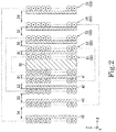
Fig. 2 is a diagram illustrating the contactless power supply coil unit of the present embodiment, and is a sectional view taken along the line II-II ofFig. 1 . -
Fig. 3 is a schematic diagram of a coil of the present embodiment as viewed from above. -
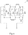
Fig. 4 is a schematic diagram illustrating a circuit configuration of the contactless power supply coil unit of the present embodiment. -
Fig. 5 is an exploded perspective view illustrating a portion of a holding member of the present embodiment. -
Fig. 6 is a front view illustrating the assembly of the contactless power supply coil unit of the present embodiment in process. - As illustrated in
Fig. 1 andFig. 2 , a contactless powersupply coil unit 10 of the present embodiment includes a plurality ofcoils 50 wound around a predetermined center axis J, and aholding member 20 that holds the plurality ofcoils 50. InFig. 1 , the center axis J extends in the up down direction. In the following description, a direction parallel to the center axis J will be simply referred to as "axial direction", a radial direction with the center axis J as the center will be simply referred to as "radial direction", and a circumferential direction with the center axis J as the center will be simply referred to as "circumferential direction". In addition, the upper side in the axial direction inFig. 1 will be simply referred to as "upper side", and the lower side in the axial direction inFig. 1 will be simply referred to as "lower side". In the present embodiment, the lower side corresponds to one axial-direction side. In the present embodiment, the upper side corresponds to the other axial-direction side. Further, it should be noted that the upper side and the lower side are simply terms for explaining the relative positional relationship between the respective parts and do not limit the actual arrangement relationship or the like. - In addition, in the XYZ axis coordinate system appropriately indicated in each drawing, the Z-axis direction is a direction parallel to the center axis J, that is, the axial direction. The X-axis direction is a direction perpendicular to the Z-axis direction and is a direction parallel to the long-side direction of the contactless power
supply coil unit 10. The X-axis direction is a direction perpendicular to both the Z-axis direction and the Y-axis direction and is a direction parallel to the short-side direction of the contactless powersupply coil unit 10. In the following description, the direction parallel to the Y-axis direction will be simply referred to as "long-side direction", and the direction parallel to the X-axis direction will be simply referred to as "short-side direction". Further, thecoils 50 are not illustrated inFig. 1 . - As illustrated in
Fig. 2 andFig. 3 , the plurality ofcoils 50 are disposed at intervals so as to overlap each other in the radial direction and form respective annular layers F stacked in the radial direction. Thecoils 50 of the present embodiment are, for example, provided as five coils, afirst coil 51 to afifth coil 55. Five layers F formed by thefirst coil 51 to thefifth coil 55, namely, a first layer F1 to a fifth layer F5, are provided. Thefirst coil 51 forms the first layer F1. Asecond coil 52 forms a second layer F2. Athird coil 53 forms a third layer F3. Afourth coil 54 forms a fourth layer F4. Thefifth coil 55 forms the fifth layer F5. Thefirst coil 51, thesecond coil 52, thethird coil 53, thefourth coil 54, and thefifth coil 55 are disposed in this order from a radial-direction inner side to a radial-direction outer side. - As illustrated in
Fig. 3 , in the present embodiment, each of thecoils 50 and each of the layers F are rectangular annular shapes elongated in the long-side direction in plan view. Thesecond coil 52 and the second layer F2 are disposed on the radial-direction outer side of thefirst coil 51 and the first layer F1 and surround thefirst coil 51 and the first layer F1. Thethird coil 53 and the third layer F3 are disposed on the radial-direction outer side of thesecond coil 52 and the second layer F2 and surround thesecond coil 52 and the second layer F2. Thefourth coil 54 and the fourth layer F4 are disposed on the radial-direction outer side of thethird coil 53 and the third layer F3 and surround thethird coil 53 and the third layer F3. Thefifth coil 55 and the fifth layer F5 are disposed on the radial-direction outer side of thefourth coil 54 and the fourth layer F4 and surround thefourth coil 54 and the fourth layer F4. - The inner diameters of the
coils 50 become respectively larger as thecoils 50 are located progressively toward the radial-direction outer side. That is, the inner diameter of thesecond coil 52 is larger than the inner diameter of thefirst coil 51. The inner diameter of thethird coil 53 is larger than the inner diameter of thesecond coil 52. The inner diameter of thefourth coil 54 is larger than the inner diameter of thethird coil 53. The inner diameter of thefifth coil 55 is larger than the inner diameter of thefourth coil 54. - As illustrated in
Fig. 4 , thecoils 50 forming the layers F that are adjacent to each other are connected to each other in series. That is, in the present embodiment, the fivecoils 50 are connected in series in the radial direction. Each of thecoils 50 has an inductance L and a resistance R. Although not illustrated, the fivecoils 50 connected in series are connected to a capacitor and an AC power source, and form an RLC series resonance circuit. The contactless powersupply coil unit 10 of the present embodiment is used, for example, in a magnetic-field-resonance type contactless power supply device. - In the case where the numbers of windings and the wire diameters of the
coils 50 are the same, the larger the inner diameter of thecoil 50, the larger the inductance L and the resistance R of thecoil 50. That is, the inductance L and the resistance R of thesecond coil 52 are larger than the inductance L and the resistance R of thefirst coil 51. The inductance L and the resistance R of thethird coil 53 are larger than the inductance L and the resistance R of thesecond coil 52. The inductance L and the resistance R of thefourth coil 54 are larger than the inductance L and the resistance R of thethird coil 53. The inductance L and the resistance R of thefifth coil 55 are larger than the inductance L and the resistance R of thefourth coil 54. As a result, the voltage applied to each of thecoils 50 increases as thecoils 50 are located progressively toward the radial-direction outer side. - As illustrated in
Fig. 2 andFig. 3 , an interval D1 between the first layer F1 and the second layer F2 is the interval between a radial-direction-outer-side surface of thefirst coil 51 and a radial-direction-inner-side surface of thesecond coil 52. An interval D2 between the second layer F2 and the third layer F3 is the interval between a radial-direction-outer-side surface of thesecond coil 52 and a radial-direction-inner-side surface of thethird coil 53. An interval D3 between the third layer F3 and the fourth layer F4 is the interval between a radial-direction-outer-side surface of thethird coil 53 and a radial-direction-inner-side surface of thefourth coil 54. An interval D4 between the fourth layer F4 and the fifth layer F5 is the interval between a radial-direction-outer-side surface of thefourth coil 54 and a radial-direction-inner-side surface of thefifth coil 55. In the present embodiment, the intervals D1 to D4 are substantially uniform over the entire circumferential direction. The intervals D1 to D4 of the layers F that are adjacent to each other increase as the intervals are located progressively toward the radial-direction outer side. That is, the interval D2 is larger than the interval D1. The interval D3 is larger than the interval D2. The interval D4 is larger than the interval D3. That is, the magnitudes of the intervals D1 to D4 are D1 <D2<D3<D4. - A potential difference V1 between the winding start of the
first coil 51 and the winding end of thesecond coil 52 illustrated inFig. 4 is the sum of the value of the voltage applied to thefirst coil 51 and the value of the voltage applied to thesecond coil 52. A potential difference V2 between the winding start of thesecond coil 52 and the winding end of thethird coil 53 is the sum of the value of the voltage applied to thesecond coil 52 and the value of the voltage applied to thethird coil 53. A potential difference V3 between the winding start of thethird coil 53 and the winding end of thefourth coil 54 is the sum of the value of the voltage applied to thethird coil 53 and the value of the voltage applied to thefourth coil 54. A potential difference V4 between the winding start of thefourth coil 54 and the winding end of thefifth coil 55 is the sum of the value of the voltage applied to thefourth coil 54 and the value of the voltage applied to thefifth coil 55. - As described above, the voltages applied to the
coils 50 increase as thecoils 50 are located progressively toward the radial-direction outer side. Therefore, the potential difference V1, the potential difference V2, the potential difference V3, and the potential difference V4 increase in this order. As a result, a discharge phenomenon is more likely to occur between thecoils 50 positioned on the radial-direction outer side. On the other hand, according to the present embodiment, because the intervals between thecoils 50 increase as the coils are located progressively toward the radial-direction outer side, thecoils 50 can be disposed further apart as the potential difference increases. Therefore, the occurrence of a discharge phenomenon can be suppressed. As a result, the number of thecoils 50 connected in series can be increased and the voltage that can be applied to each of thecoils 50 can also be increased. Therefore, it is possible to increase the amount of electric power that can be transmitted by the contactless power supply device in which the contactless powersupply coil unit 10 is mounted. - As illustrated in
Fig. 1 , the holdingmember 20 includes acore member 30, a plurality ofcylindrical members 40, and acore 60. Thecore member 30 is disposed along the center axis J. Thecore member 30 has a substantially rectangular parallelepiped shape that is elongated in the long-side direction. - The plurality of
cylindrical members 40 are disposed at intervals on the radial-direction outer side of thecore member 30 and have a cylindrical shape that surrounds thecore member 30. As illustrated inFig. 1 , in the present embodiment, each of thecylindrical members 40 has a rectangular cylindrical shape that opens in the up down direction and is elongated in the long-side direction. The plurality ofcylindrical members 40 are disposed at intervals so as to overlap each other in the radial direction. In the present embodiment, fourcylindrical members 40, namely, a firstcylindrical member 41, a secondcylindrical member 42, a thirdcylindrical member 43, and a fourthcylindrical member 44, are provided. The firstcylindrical member 41 to the fourthcylindrical member 44 have substantially the same structure except for differences in size. Therefore, in the following description, only the firstcylindrical member 41 will be described as representative in some cases. - As illustrated in
Fig. 2 , among the plurality ofcoils 50, thefirst coil 51 disposed most toward the radial-direction inner side is wound around thecore member 30. Thefirst coil 51 is wound along the axial direction from a lower end portion of thecore member 30 toward an upper end portion of thecore member 30. Among the plurality ofcoils 50, each of the other ones of thecoils 50 disposed on the radial-direction outer side of thefirst coil 51 is wound around a corresponding one of the plurality ofcylindrical members 40. Specifically, thesecond coil 52 is wound around the firstcylindrical member 41. Thethird coil 53 is wound around the secondcylindrical member 42. Thefourth coil 54 is wound around the thirdcylindrical member 43. Thefifth coil 55 is wound around the fourthcylindrical member 44. - Therefore, it is easy to dispose the plurality of
coils 50 in the radial direction. In addition, because the intervals D1 to D4 can be adjusted by adjusting the inner diameters and the outer diameters of thecylindrical members 40, it is easy to increase the intervals D1 to D4 toward the outer side in the radial direction. In addition, as compared with the case where thecoils 50 are stacked on each other with, for example, an insulating tape or the like therebetween, it is easy for air to pass between thecoils 50, and heat is not likely to be trapped in the contactless powersupply coil unit 10. As a result, it is possible to suppress the contactless powersupply coil unit 10 from reaching a high temperature. In addition, because thecoils 50 adjacent to the radial-direction inner side of thecylindrical members 40 can be held down from the radial-direction outer side by thecylindrical members 40, it is possible to suppress loosening of thecoils 50. - The
second coil 52 is wound in the axial direction from an upper end portion of the firstcylindrical member 41 toward a lower end portion of the firstcylindrical member 41. Thethird coil 53 is wound in the axial direction from a lower end portion of the secondcylindrical member 42 toward an upper end portion of the secondcylindrical member 42. Thefourth coil 54 is wound in the axial direction from an upper end portion of the thirdcylindrical member 43 toward a lower end portion of the thirdcylindrical member 43. Thefifth coil 55 is wound in the axial direction from a lower end portion of the fourthcylindrical member 44 toward an upper end portion of the fourthcylindrical member 44. That is, among thecore member 30 and the plurality ofcylindrical members 40, for two members adjacent to each other, axial-direction end portions of thecoils 50 that each correspond to the winding start of thecoil 50 to be wound and axial-direction end portions of thecoils 50 that each correspond to the winding end of thecoil 50 to be wound, are located on opposite upper and lower sides. - As illustrated in
Fig. 5 , thecore member 30 has abody portion 31, an upper-side flange portion 32, and a lower-side flange portion 33. Thebody portion 31 is a portion around which thefirst coil 51 is wound. Thebody portion 31 has a substantially rectangular parallelepiped shape that is elongated in the long-side direction. Thebody portion 31 has ahole portion 31f that is recessed in the axial direction. That is, thecore member 30 has thehole portion 31f that is recessed in the axial direction. In the present embodiment, thebody portion 31 has a bottomed square cylindrical shape. The plan view shape of thehole portion 31f is a rectangular shape that is elongated in the long-side direction. Thehole portion 31f is arranged at the center of thecore member 30 in plan view. Further, thebody portion 31 may have a cylindrical shape and thebody portion 31 may have a hole penetrating in the axial direction. - The
body portion 31 has a plurality ofgrooves 31c recessed from a radial-direction-outer-side surface to the radial-direction inner side. That is, thecore member 30 has the plurality ofgrooves 31c recessed from a radial-direction-outer-side surface to the radial-direction inner side. The plurality ofgrooves 31c extend along the circumferential direction. In the present embodiment, a predetermined number of thegrooves 31c are arranged side by side in the axial direction to formgroove groups 31e. The plurality ofgroove groups 31e are provided along the circumferential direction. The number of thegrooves 31c forming each of thegroove groups 31e is the same as the number of windings of thefirst coil 51. - The
first coil 51, that is, thecoil 50, is wound along thegrooves 31c. Therefore, it is easy to wind thefirst coil 51 around thecore member 30. In addition, as in thegroove groups 31e of the present embodiment, by making the number of grooves arranged in the axial direction the same as the number of windings of thefirst coil 51, it is not necessary to count the number of windings when winding thefirst coil 51, which is convenient. - The
body portion 31 has recessedportions portions 31a are arranged on surfaces extending in the long-side direction among radial-direction-outer-side surfaces of thebody portion 31, and are recessed in the short-side direction. The recessedportions 31a extend in the axial direction from an upper end to a lower end of thebody portion 31. The plurality of recessedportions 31a are provided along the long-side direction, and are arranged between thegroove groups 31e adjacent to each other in the long-side direction. The shape of each of the recessedportions 31a in plan view is a V shape opening to the radial-direction outer side. - The maximum value of the recess amount of the recessed
portions 31a is larger than the maximum value of the recess amount of thegrooves 31c. Therefore, in each of the recessedportions 31a, a gap can be provided between thefirst coil 51 and thebody portion 31. As a result, air can pass through the inside of thefirst coil 51, and thefirst coil 51 is easily cooled. Therefore, it is more difficult for heat to be trapped in the contactless powersupply coil unit 10 and it is possible to further suppress the contactless powersupply coil unit 10 from reaching a high temperature. - The recessed
portions 31d are disposed on short-side-direction-extending surfaces among the radial-direction-outer-side surfaces of thebody portion 31 and are recessed in the long-side direction. The recessedportions 31d extend in the axial direction from the upper end to the lower end of thebody portion 31. Each of the recessedportions 31d in plan view has a V shape opening to the radial-direction outer side. The maximum value of the recess amount of the recessedportions 31d is larger than the maximum value of the recess amount of thegrooves 31c. Therefore, also in the recessedportions 31d, a gap can be provided between thefirst coil 51 and thebody portion 31. As a result, air can be more easily passed through the inside of thefirst coil 51 and thefirst coil 51 is more easily cooled. Therefore, it is more difficult for heat to be trapped in the contactless powersupply coil unit 10 and it is possible to further suppress the contactless powersupply coil unit 10 from reaching a high temperature. - The
body portion 31 includes ahook portion 34. Thehook portion 34 has a hook shape protruding from a bottom surface of one of the recessedportions 31a. A conductor forming thecoils 50 is hooked to thehook portion 34. Thereby, thecoils 50 can be stably held on thecore member 30. - The
core member 30 has second throughholes 31b penetrating thebody portion 31 of thecore member 30 in a direction perpendicular to the axial direction. In the present embodiment, the second throughholes 31b penetrate thecore member 30 in the short-side direction. A plurality of the second throughholes 31b are provided. The second throughholes 31b are arranged so as to overlap the recessedportions 31a in the circumferential direction. Three second throughholes 31b are provided for each of the recessedportions 31a. The three second throughholes 31b in the corresponding one of the recessedportions 31a are arranged side by side in the axial direction. The shape of each of the second throughholes 31b viewed in the short-side direction is a circular shape. Air can pass through the second throughholes 31b in the short-side direction with respect to thecore member 30 around which thefirst coil 51 is wound. Therefore, thefirst coil 51 is more easily cooled. Therefore, it is more difficult for heat to be trapped in the contactless powersupply coil unit 10 and it is possible to further suppress the contactless powersupply coil unit 10 from reaching a high temperature. Further, the second throughholes 31b may penetrate thecore member 30 in the long-side direction. - The outer shape of the upper-
side flange portion 32 is a rectangular frame shape. The upper-side flange portion 32 is fixed to the radial-direction outer side of an upper end portion of thebody portion 31 and surrounds the upper end portion of thebody portion 31. The outer shape of the lower-side flange portion 33 is a rectangular frame shape. The lower-side flange portion 33 is fixed to the radial-direction outer side of a lower end portion of thebody portion 31 and surrounds the lower end portion of thebody portion 31. - The first
cylindrical member 41 has awall portion 41c, an upper-side flange portion 41d, and a lower-side flange portion 41e. Thewall portion 41c is a rectangular cylindrical portion around which thesecond coil 52 is wound. The upper-side flange portion 41d is connected to an upper end portion of thewall portion 41c. The outer shape of the upper-side flange portion 41d is a rectangular frame shape. The upper-side flange portion 41d includes an inner-side flange portion 45a and an outer-side flange portion 45b. - The upper-
side flange portion 41d includes the inner-side flange portion 45a and the outer-side flange portion 45b. The outer-side flange portion 45b is continuously provided on the radial-direction outer side of the inner-side flange portion 45a. The axial-direction position of the outer-side flange portion 45b is lower than the axial-direction position of the inner-side flange portion 45a. A step that descends from the radial-direction inner side to the radial-direction outer side is formed by the inner-side flange portion 45a and the outer-side flange portion 45b. - The lower-
side flange portion 41e is connected to a lower end portion of thewall portion 41c. The lower-side flange portion 41e has a rectangular frame shape. Although not illustrated, the lower-side flange portion 41e includes the inner-side flange portion 45a and the outer-side flange portion 45b similarly to the upper-side flange portion 41d. The inner-side flange portion 45a and the outer-side flange portion 45b of the lower-side flange portion 41e are similar except that the inner-side flange portion 45a and the outer-side flange portion 45b of the lower-side flange portion 41e are upside down with respect to the inner-side flange portion 45a and the outer-side flange portion 45b of the upper-side flange portion 41d. - As illustrated in
Fig. 1 andFig. 5 , the inner-side flange portion 45a is fitted to the upper end portion of thebody portion 31. The inner-side flange portion 45a overlaps the upper-side flange portion 32 of thecore member 30 in the axial direction. A lower surface of the inner-side flange portion 45a makes contact with an upper surface of the upper-side flange portion 32. An upper surface of the inner-side flange portion 45a is disposed at the same position in the axial direction as an upper surface of thebody portion 31. Although not illustrated, the inner-side flange portion 45a of the lower-side flange portion 41e is fitted to the lower end portion of thebody portion 31. The inner-side flange portion 45a of the lower-side flange portion 41e overlaps the lower-side flange portion 33 of thecore member 30 in the axial direction. An upper surface of the inner-side flange portion 45a of the lower-side flange portion 41e is in contact with a lower surface of the lower-side flange portion 33. The lower surface of the inner-side flange portion 45a of the lower-side flange portion 41e is disposed at the same position in the axial direction as the lower surface of thebody portion 31. - The inner-side flange portions on both axial-direction sides of the second
cylindrical member 42 respectively surround the inner-side flange portions 45a on both axial-direction sides of the firstcylindrical member 41 from the radial-direction outer side and are respectively fitted to the inner-side flange portions 45a of the firstcylindrical member 41. The inner-side flange portions on both axial-direction sides of the secondcylindrical member 42 respectively overlap and contact the outer-side flange portions 45b on both axial-direction sides of the firstcylindrical member 41 in the axial direction. The inner-side flange portions on both axial-direction sides of the thirdcylindrical member 43 respectively surround the inner-side flange portions on both axial-direction sides of the secondcylindrical member 42 from the outside in the radial direction and are respectively fitted to the inner-side flange portions of the secondcylindrical member 42. The inner-side flange portions on both axial-direction sides of the thirdcylindrical member 43 respectively overlap and contact the outer-side flange portions on both axial-direction sides of the secondcylindrical member 42 in the axial direction. The inner-side flange portions on both axial-direction sides of the fourthcylindrical member 44 respectively surround the inner-side flange portions on both axial-direction sides of the thirdcylindrical member 43 from the radial-direction outer side and are respectively fitted to the inner-side flange portions of the thirdcylindrical member 43. The inner-side flange portions on both axial-direction sides of the fourthcylindrical member 44 respectively overlap and contact the outer-side flange portions on both axial-direction sides of the thirdcylindrical member 43 in the axial direction. As described above, thecore member 30 and thecylindrical members 40 are connected to each other. According to this configuration, because the respectivecylindrical members 40 are assembled while being guided by thecore member 30 or a corresponding one of thecylindrical members 40 located on the radial-direction inner side, the assembler can easily assemble thecylindrical members 40. - The upper surfaces of the inner-side flange portions of the upper-side flange portions of the
cylindrical members 40 are arranged at the same position in the axial direction. The lower surfaces of the inner-side flange portions of the lower-side flange portions of thecylindrical members 40 are arranged at the same position in the axial direction. - As illustrated in
Fig. 5 , thewall portion 41c has first throughholes 41f penetrating thewall portion 41c from a radial-direction-inner-side surface to a radial-direction-outer-side surface. That is, each of thecylindrical members 40 has the first throughholes 41f that penetrate thewall portion 41c of thecylindrical member 40 from the radial-direction-inner-side surface of thecylindrical member 40 to the radial-direction-outer-side surface of thecylindrical member 40. Therefore, air can pass through the firstcylindrical member 41 via the first throughholes 41f, and thefirst coil 51 and thesecond coil 52 are easily cooled. Therefore, it is more difficult for heat to be trapped in the contactless powersupply coil unit 10 and it is possible to further suppress the contactless powersupply coil unit 10 from reaching a high temperature. - In the present embodiment, a plurality of the first through
holes 41f are provided along the circumferential direction. The first throughholes 41f include the first throughholes 41f penetrating thewall portion 41c in the long-side direction and the first throughholes 41f penetrating thewall portion 41c in the short-side direction. The shape of the first throughholes 41f is rectangular as viewed along the long-side direction or the short-side direction. The first throughholes 41f extend from the upper end portion to lower end portion of thewall portion 41c over the entirety of thewall portion 41c in the axial direction. In the present embodiment, the region where the first throughholes 41f are provided in thewall portion 41c is larger than the region where the first throughholes 41f are not provided in thewall portion 41c. By providing the first throughholes 41f in this manner, thewall portion 41c in the present embodiment has a plurality of plate-like pillar shapes connecting the upper-side flange portion 41d and the lower-side flange portion 41e in the axial direction. - The
wall portion 41c has a plurality ofgrooves 41g recessed from the radial-direction-outer-side surface toward the radial-direction inner side. That is, the plurality ofcylindrical members 40 have a plurality of thegrooves 41g recessed from the radial-direction-outer-side surface to the radial-direction inner side. The plurality ofgrooves 41g extend along the circumferential direction. In the present embodiment, a predetermined number of thegrooves 41g are arranged side by side in the axial direction to form agroove group 41i. Thegroove group 41i is provided in thewall portion 41c. Thegrooves 41g extend from one end to the other end in the circumferential direction. The number of thegrooves 41g forming thegroove group 41i is the same as the number of windings of thesecond coil 52. - The
second coil 52, that is, thecoil 50 is wound along thegrooves 41g. Therefore, it is easy to wind thesecond coil 52 around the firstcylindrical member 41. In addition, as in thegroove group 41i of the present embodiment, by making the number of grooves arranged in the axial direction the same as the number of windings of thesecond coil 52, it is not necessary to count the number of windings when winding thesecond coil 52, which is convenient. - In the present embodiment, the
cylindrical members 40 are formed by connecting a plurality of cylindrical member pieces divided in the circumferential direction. Therefore, thecylindrical members 40 can be formed by bringing the cylindrical member pieces together from the radial-direction outer side of thecoils 50 and combining them after thecoils 50 have been wound around thecore member 30 or thecylindrical members 40. As a result, it is easy to assemble the contactless powersupply coil unit 10. - In the present embodiment, each of the
cylindrical members 40 is formed by connecting two cylindrical member pieces facing each other in the long-side direction. As illustrated inFig. 1 , the firstcylindrical member 41 is formed by connecting acylindrical member piece 41a and acylindrical member piece 41b. The secondcylindrical member 42 is formed by connecting acylindrical member piece 42a and acylindrical member piece 42b. The thirdcylindrical member 43 is formed by connecting acylindrical member piece 43a and acylindrical member piece 43b. The fourthcylindrical member 44 is formed by connecting acylindrical member piece 44a and acylindrical member piece 44b. - As illustrated in
Fig. 1 , in the firstcylindrical member 41, the positions of twoconnection portions cylindrical member pieces cylindrical member 42, the positions of twoconnection portions cylindrical member pieces cylindrical member 43, the positions of twoconnection portions cylindrical member pieces cylindrical member 44, the positions of twoconnection portions cylindrical member pieces - The connection portions of one of the
cylindrical members 40 and the connection portions of another one of thecylindrical members 40 among adjacent ones of thecylindrical members 40 are arranged at different positions in the circumferential direction, that is, in the long-side direction in the present embodiment. Specifically, for example, theconnection portion 41j of the firstcylindrical member 41 is disposed at a position different from theconnection portion 42j of the secondcylindrical member 42 in the long-side direction. - As illustrated in
Fig. 6 , in theconnection portion 41j, holdingholes 41h that penetrate thewall portion 41c of the firstcylindrical member 41 from a radial-direction-inner-side surface of the firstcylindrical member 41 to a radial-direction-outer-side surface of the firstcylindrical member 41 are provided. In the present embodiment, the holdingholes 41h penetrate thewall portion 41c in the short-side direction. The holdingholes 41h are provided in the upper end portion of thewall portion 41c and the lower end portion of thewall portion 41c. The holdingholes 41h are provided across thecylindrical member piece 41a and thecylindrical member piece 41b. Although illustration is omitted, holding holes are similarly provided for theconnection portion 41k. - A
conductive wire 56 connecting thecoils 50 to each other is passed through the holdingholes 41h. That is, the holdingholes 41h hold theconductive wire 56. Specifically, inFig. 6 , theconductive wire 56 extending from the winding end of thefirst coil 51 is held in the holdinghole 41h. Therefore, after thefirst coil 51 is wound, it is possible to stably hold a coilconductive wire portion 57 that is wound next and becomes thesecond coil 52. This makes it easy to wind thesecond coil 52. In addition, it is possible to suppress loosening of thefirst coil 51. - The core 60 illustrated in
Fig. 5 has a rectangular parallelepiped shape that extends in the axial direction. The plan view shape of thecore 60 is a rectangular shape elongated in the long-side direction. Thecore 60 is made to pass on the radial-direction inner side of thecoils 50. Thecore 60 is inserted and held in thehole portion 31f. In the present embodiment, thecore 60 is fitted into thehole portion 31f. Thecore 60 is a magnetic body. Thecore 60 is, for example, a ferrite core. By providing thecore 60, it is possible to improve the power transmission efficiency of the contactless power supply device in which the contactless powersupply coil unit 10 is mounted. - Next, a method of assembling the contactless power
supply coil unit 10 of the present embodiment will be described. The assembler winds a conductive wire around thecore member 30 from the lower side to the upper side and creates thefirst coil 51. As illustrated inFig. 5 , the assembler brings thecylindrical member piece 41a and thecylindrical member piece 41b toward thecore member 30 from both sides in the long-side direction and combines them as illustrated inFig. 6 . At this time, the assembler inserts the upper-side flange portion 41d and the lower-side flange portion 41e of the firstcylindrical member 41 into thebody portion 31. Thereby, the firstcylindrical member 41 is manufactured, and thefirst coil 51 is held down from the radial-direction outer side. The coilconductive wire portion 57 on the winding end side of thefirst coil 51 is drawn out of the firstcylindrical member 41 from the holdinghole 41h on the upper side. The base of the coilconductive wire portion 57, that is, theconductive wire 56 connecting thecoils 50 to each other is held in the holdinghole 41h. - Thereafter, the assembler winds the coil
conductive wire portion 57 around the firstcylindrical member 41 from the upper side to the lower side to manufacture thesecond coil 52. Then, the assembler brings thecylindrical member piece 42a and thecylindrical member piece 42b toward the firstcylindrical member 41 from both sides in the long-side direction and combines them. At this time, the assembler engages the upper-side flange portion and the lower-side flange portion of the secondcylindrical member 42 with the inner-side flange portions of the firstcylindrical member 41. As a result, the secondcylindrical member 42 is manufactured and thesecond coil 52 is held down from the radial-direction outer side. Thereafter, similarly, thecoils 50 and thecylindrical members 40 are alternately fabricated, and the assembler assembles the contactless powersupply coil unit 10. According to this configuration, the assembler can assemble each of thecylindrical members 40 without stopping the operation of winding thecoils 50. - The present invention is not limited to the above-described embodiment, and other configurations may be adopted. The intervals D1 to D4 may be any values as long as they become larger as the intervals are located progressively toward the radial-direction outer side. For example, the difference between the interval D1 and the interval D2, the difference between the interval D2 and the interval D3, and the difference between the interval D3 and the interval D4 may be the same or different. In addition, the number of the
coils 50 may be two or more, four or less, or six or more. - In addition, in another embodiment, each of the
cylindrical members 40 may be configured by connecting two cylindrical member pieces facing each other in the axial direction. The assembler winds a conductive wire around thecore member 30 from the lower side to the upper side and creates thefirst coil 51. Then, the assembler brings thecylindrical member piece 41a on the axial-direction upper side and thecylindrical member piece 41b on the axial-direction lower side toward thecore member 30 from both sides in the axial direction and combines them. At this time, thewall portion 41c is formed of two cylindrical member pieces. Thewall portion 41c is assembled by chucking two cylindrical member pieces. Thereby, the firstcylindrical member 41 is manufactured, and thefirst coil 51 is held down from the radial-direction outer side. The coilconductive wire portion 57 on the winding end side of thefirst coil 51 is drawn out of the firstcylindrical member 41 from the holdinghole 41h on the upper side. The base of the coilconductive wire portion 57, that is, theconductive wire 56 connecting thecoils 50 to each other is held in the holdinghole 41h. Here, thewall portion 41c has the holdinghole 41h for holding theconductive wire 56. The holdinghole 41h is formed by two cylindrical member pieces. Thereafter, the assembler winds the coilconductive wire portion 57 around the firstcylindrical member 41 from the upper side to the lower side to manufacture thesecond coil 52. Thereafter, similarly, thecoils 50 and thecylindrical members 40 are alternately fabricated, and the assembler assembles the contactless powersupply coil unit 10. Therefore, according to this configuration, the assembler can assemble each of thecylindrical members 40 without stopping the operation of winding thecoils 50. - In addition, the shape of the
coils 50 in plan view is not particularly limited as long as thecoils 50 are wound around the center axis J, and may be an annular shape, an elliptical annular shape, a triangular shape, or an annular shape having five corners or more. In addition, the plan view shape of thecylindrical members 40 can be appropriately changed according to the plan view shape of thecoils 50. - In addition, the number of the cylindrical member pieces forming the plurality of
cylindrical members 40 may be three or more. In addition, each of the plurality ofcylindrical members 40 may be a single member. In this case, the assembler moves thecylindrical members 40, which have a cylindrical shape, in the axial direction, arranges them on the radial-direction outer side of thecore member 30 or a corresponding one of thecylindrical members 40, and assembles thecylindrical members 40. In addition, thecylindrical members 40 need not be provided. In this case, for example, the intervals D1 to D4 between thecoils 50 may be formed by an insulating tape or the like. In this case, the insulating tape or the like corresponds to the holding member. - The application of the contactless power supply device in which the contactless power supply coil unit is mounted according to the above embodiment is not particularly limited, and is used, for example, for power supply for an automatic guided vehicle.
- Each of the above-described configurations can be appropriately combined to the extent they are not inconsistent with each other.
- A contact power supply coil unit includes a plurality of coils wound around a predetermined center axis and a holding member that holds the plurality of coils. The plurality of coils are disposed at intervals so as to overlap each other in a radial direction and form respective annular layers that are stacked in the radial direction. The coils forming the layers that are adjacent to each other are connected in series to each other. The intervals between the layers that are adjacent to each other increase as the intervals are located progressively toward a radial-direction outer side.
- In the contactless power supply coil unit according to Feature 1, the holding member includes a core member disposed along the center axis and a plurality of cylindrical members that are disposed at intervals on the radial-direction outer side of the core member and that have a cylindrical shape that surrounds the core member. The plurality of cylindrical members are disposed at intervals so as to overlap each other in the radial direction. Among the plurality of coils, a first coil disposed most toward a radial-direction inner side is wound around the core member. Among the plurality of coils, each of the other coils disposed on the radial-direction outer side of the first coil is wound around a corresponding one of the plurality of cylindrical members.
- In the contactless power supply coil unit according to Feature 2, each of the cylindrical members has first through holes that penetrate a wall portion of the cylindrical member from a radial-direction-inner-side surface of the cylindrical member to a radial-direction-outer-side surface of the cylindrical member.
- In the contactless power supply coil unit according to Feature 2 or 3, the holding member includes a core, the core member includes a hole portion recessed in an axial direction, and the core is inserted and held in the hole portion.
- In the contactless power supply coil unit according to any one of Features 2 to 3, the core member has second through holes penetrating the core member in a direction perpendicular to an axial direction.
- In the contactless power supply coil unit according to any one of Features 2 to 5, the core member and the plurality of cylindrical members have a plurality of grooves recessed from a radial-direction-outer-side surface toward the radial-direction inner side, the plurality of grooves extend along a circumferential direction, and the coils are wound along the grooves.
- In the contactless power supply coil unit according to any one of Features 2 to 6, each of the cylindrical members is formed by connecting a plurality of cylindrical member pieces divided in the circumferential direction.
- In the contactless power supply coil unit according to Feature 7, in connection portions where the cylindrical member pieces are connected to each other, holding holes that penetrate the wall portion of each of the cylindrical members from the radial-direction-inner-side surface of the cylindrical member to the radial-direction-outer-side surface of the cylindrical member are provided, and a conductive wire connecting the coils is made to penetrate and is held by the holding holes.
-
- 10
- contactless power supply coil unit
- 20
- holding member
- 30
- core member
- 31b
- second through hole
- 31c, 41g
- grooves
- 31f
- hole portion
- 40
- cylindrical members
- 41a, 41b, 42a, 42b, 43a, 43b, 44a, 44b
- cylindrical member pieces
- 41c
- wall portion
- 41f
- first through holes
- 41h
- holding holes
- 41j, 41k, 42j, 42k, 43j, 43k, 44j, 44k
- connection portions
- 50
- coils
- 51
- first coil
- 56
- conductive wire
- 60
- core
- D1, D2, D3, D4
- intervals
- F
- layer
- J
- center axis
Claims (8)
- A contactless power supply coil unit comprising:a plurality of coils wound around a predetermined center axis; anda holding member that holds the plurality of coils,wherein the plurality of coils are disposed at intervals so as to overlap each other in a radial direction and form respective annular layers that are stacked in the radial direction,wherein the coils forming the layers that are adjacent to each other are connected in series to each other, andwherein the intervals between the layers that are adjacent to each other increase as the intervals are located progressively toward a radial-direction outer side.
- The contactless power supply coil unit according to Claim 1,
wherein the holding member includes
a core member that is disposed along the center axis, and
a plurality of cylindrical members that are disposed with intervals therebetween on the radial-direction outer side of the core member and have a cylindrical shape that surrounds the core member,
wherein the plurality of cylindrical members are disposed at intervals so as to overlap each other in the radial direction,
wherein, among the plurality of coils, a first coil disposed most toward a radial-direction inner side is wound around the core member, and
wherein, among the plurality of coils, each of the other coils disposed on the radial-direction outer side of the first coil is wound around a corresponding one of the plurality of cylindrical members. - The contactless power supply coil unit according to Claim 2,
wherein each of the cylindrical members has first through holes that penetrate a wall portion of the cylindrical member from a radial-direction-inner-side surface of the cylindrical member to a radial-direction-outer-side surface of the cylindrical member. - The contactless power supply coil unit according to Claim 2 or 3,
wherein the holding member includes a core,
wherein the core member includes a hole portion recessed in an axial direction, and
wherein the core is inserted and held in the hole portion. - The contactless power supply coil unit according to any one of Claims 2 to 3,
wherein the core member has second through holes penetrating the core member in a direction perpendicular to an axial direction. - The contactless power supply coil unit according to any one of Claims 2 to 5,
wherein the core member and the plurality of cylindrical members have a plurality of grooves recessed from a radial-direction-outer-side surface toward the radial-direction inner side,
wherein the plurality of grooves extend along a circumferential direction, and
wherein the coils are wound along the grooves. - The contactless power supply coil unit according to any one of Claims 2 to 6,
wherein each of the cylindrical members is formed by connecting a plurality of cylindrical member pieces divided in the circumferential direction. - The contactless power supply coil unit according to Claim 7,
wherein, in connection portions where the cylindrical member pieces are connected to each other, holding holes that penetrate the wall portion of each of the cylindrical members from the radial-direction-inner-side surface of the cylindrical member to the radial-direction-outer-side surface of the cylindrical member are provided, and
wherein a conductive wire connecting the coils is made to penetrate and is held by the holding holes.
Applications Claiming Priority (2)
| Application Number | Priority Date | Filing Date | Title |
|---|---|---|---|
| JP2016189056 | 2016-09-28 | ||
| PCT/JP2017/034605 WO2018062117A1 (en) | 2016-09-28 | 2017-09-26 | Contactless power feeding coil unit |
Publications (2)
| Publication Number | Publication Date |
|---|---|
| EP3522184A1 true EP3522184A1 (en) | 2019-08-07 |
| EP3522184A4 EP3522184A4 (en) | 2020-05-13 |
Family
ID=61759734
Family Applications (1)
| Application Number | Title | Priority Date | Filing Date |
|---|---|---|---|
| EP17856068.6A Withdrawn EP3522184A4 (en) | 2016-09-28 | 2017-09-26 | Contactless power feeding coil unit |
Country Status (5)
| Country | Link |
|---|---|
| US (1) | US20190207432A1 (en) |
| EP (1) | EP3522184A4 (en) |
| JP (1) | JPWO2018062117A1 (en) |
| CN (1) | CN109643607B (en) |
| WO (1) | WO2018062117A1 (en) |
Families Citing this family (2)
| Publication number | Priority date | Publication date | Assignee | Title |
|---|---|---|---|---|
| JPWO2018062118A1 (en) * | 2016-09-28 | 2019-08-15 | 日本電産株式会社 | Non-contact power supply coil unit |
| CN112201434B (en) * | 2020-09-18 | 2021-12-03 | 华中科技大学 | Multilayer inductor for special power supply system and preparation method thereof |
Family Cites Families (9)
| Publication number | Priority date | Publication date | Assignee | Title |
|---|---|---|---|---|
| JPS5880753U (en) * | 1981-11-27 | 1983-06-01 | 工業技術院長 | charging device |
| CN101971452B (en) * | 2008-03-13 | 2014-06-04 | 捷通国际有限公司 | Inductive Power System with Multiple Coil Primary |
| KR101136532B1 (en) * | 2009-09-15 | 2012-04-17 | 주식회사 삼보컴퓨터 | Contactless charging device, contactless charging battery device and contactless charging system comprising the same |
| JP5471283B2 (en) | 2009-10-19 | 2014-04-16 | Tdk株式会社 | Wireless power feeding device, wireless power receiving device, and wireless power transmission system |
| JP2011229202A (en) * | 2010-04-15 | 2011-11-10 | Panasonic Corp | Wireless power transmission coil |
| CN102906831A (en) * | 2010-05-28 | 2013-01-30 | 皇家飞利浦电子股份有限公司 | Improved receiver coil |
| JP2012244763A (en) * | 2011-05-19 | 2012-12-10 | Sony Corp | Power supply device, power supply system and electronic device |
| CN104008846A (en) * | 2013-02-25 | 2014-08-27 | 捷通国际有限公司 | Variable pitch spiral coil |
| CN204480870U (en) * | 2015-01-15 | 2015-07-15 | 宁波微鹅电子科技有限公司 | A kind of transmitting coil structure of high quality factor |
-
2017
- 2017-09-26 JP JP2018542565A patent/JPWO2018062117A1/en active Pending
- 2017-09-26 CN CN201780051042.XA patent/CN109643607B/en not_active Expired - Fee Related
- 2017-09-26 US US16/332,822 patent/US20190207432A1/en not_active Abandoned
- 2017-09-26 WO PCT/JP2017/034605 patent/WO2018062117A1/en not_active Ceased
- 2017-09-26 EP EP17856068.6A patent/EP3522184A4/en not_active Withdrawn
Also Published As
| Publication number | Publication date |
|---|---|
| CN109643607A (en) | 2019-04-16 |
| US20190207432A1 (en) | 2019-07-04 |
| EP3522184A4 (en) | 2020-05-13 |
| JPWO2018062117A1 (en) | 2019-09-05 |
| CN109643607B (en) | 2021-01-12 |
| WO2018062117A1 (en) | 2018-04-05 |
Similar Documents
| Publication | Publication Date | Title |
|---|---|---|
| US11616407B2 (en) | Segment-core coupled body and method of manufacturing armature | |
| EP2782224B1 (en) | Coil manufacturing method | |
| US10476337B2 (en) | Stator | |
| US11222745B2 (en) | Coil and non-contact power supply device | |
| EP3159903B1 (en) | Resonant high current density transformer | |
| US20140028433A1 (en) | Transformer | |
| JP6341288B2 (en) | Stator assembly method and stator | |
| EP3365901B1 (en) | Segmented core cap system for toroidal transformers | |
| US20170178792A1 (en) | Voltage transformer | |
| US20060192441A1 (en) | Stator of reciprocating motor | |
| KR20170102744A (en) | Busbar assembly and motor having the same | |
| US20190207432A1 (en) | Contactless power supply coil unit | |
| US8410885B2 (en) | Combined transformer | |
| JP2018207060A (en) | Non-contact power feeding device, coil and manufacturing method for coil | |
| US6700286B2 (en) | Stator structure of reciprocating motor | |
| JP6499723B2 (en) | Non-contact power feeding device, coil and coil manufacturing method | |
| KR101753189B1 (en) | Transformer with multi-stacking | |
| EP3189528B1 (en) | Bobbin assembly and method of producing a bobbin assembly | |
| EP3522180A1 (en) | Coil unit for contactless power supply | |
| US20250201458A1 (en) | Electronic component, in particular three-phase transformer for an isolated voltage converter | |
| US20250105695A1 (en) | Stator and motor | |
| JP6501681B2 (en) | Coil support |
Legal Events
| Date | Code | Title | Description |
|---|---|---|---|
| PUAI | Public reference made under article 153(3) epc to a published international application that has entered the european phase |
Free format text: ORIGINAL CODE: 0009012 |
|
| STAA | Information on the status of an ep patent application or granted ep patent |
Free format text: STATUS: REQUEST FOR EXAMINATION WAS MADE |
|
| 17P | Request for examination filed |
Effective date: 20190416 |
|
| AK | Designated contracting states |
Kind code of ref document: A1 Designated state(s): AL AT BE BG CH CY CZ DE DK EE ES FI FR GB GR HR HU IE IS IT LI LT LU LV MC MK MT NL NO PL PT RO RS SE SI SK SM TR |
|
| AX | Request for extension of the european patent |
Extension state: BA ME |
|
| DAV | Request for validation of the european patent (deleted) | ||
| DAX | Request for extension of the european patent (deleted) | ||
| A4 | Supplementary search report drawn up and despatched |
Effective date: 20200417 |
|
| RIC1 | Information provided on ipc code assigned before grant |
Ipc: H01F 38/14 20060101AFI20200409BHEP Ipc: B60M 7/00 20060101ALI20200409BHEP Ipc: H01F 27/32 20060101ALN20200409BHEP Ipc: H01F 27/28 20060101ALI20200409BHEP Ipc: H01F 5/02 20060101ALI20200409BHEP |
|
| STAA | Information on the status of an ep patent application or granted ep patent |
Free format text: STATUS: THE APPLICATION IS DEEMED TO BE WITHDRAWN |
|
| 18D | Application deemed to be withdrawn |
Effective date: 20201118 |