EP3522139A1 - Flexible screen support device and flexible screen - Google Patents
Flexible screen support device and flexible screen Download PDFInfo
- Publication number
- EP3522139A1 EP3522139A1 EP16917158.4A EP16917158A EP3522139A1 EP 3522139 A1 EP3522139 A1 EP 3522139A1 EP 16917158 A EP16917158 A EP 16917158A EP 3522139 A1 EP3522139 A1 EP 3522139A1
- Authority
- EP
- European Patent Office
- Prior art keywords
- flexible screen
- board
- coupling
- support device
- assembly
- Prior art date
- Legal status (The legal status is an assumption and is not a legal conclusion. Google has not performed a legal analysis and makes no representation as to the accuracy of the status listed.)
- Withdrawn
Links
- 230000008878 coupling Effects 0.000 claims description 44
- 238000010168 coupling process Methods 0.000 claims description 44
- 238000005859 coupling reaction Methods 0.000 claims description 44
- 230000008901 benefit Effects 0.000 description 2
- 230000008602 contraction Effects 0.000 description 2
- 230000007812 deficiency Effects 0.000 description 1
- 238000010586 diagram Methods 0.000 description 1
- 238000005516 engineering process Methods 0.000 description 1
- 238000000034 method Methods 0.000 description 1
Images



Classifications
-
- F—MECHANICAL ENGINEERING; LIGHTING; HEATING; WEAPONS; BLASTING
- F16—ENGINEERING ELEMENTS AND UNITS; GENERAL MEASURES FOR PRODUCING AND MAINTAINING EFFECTIVE FUNCTIONING OF MACHINES OR INSTALLATIONS; THERMAL INSULATION IN GENERAL
- F16M—FRAMES, CASINGS OR BEDS OF ENGINES, MACHINES OR APPARATUS, NOT SPECIFIC TO ENGINES, MACHINES OR APPARATUS PROVIDED FOR ELSEWHERE; STANDS; SUPPORTS
- F16M11/00—Stands or trestles as supports for apparatus or articles placed thereon ; Stands for scientific apparatus such as gravitational force meters
- F16M11/02—Heads
- F16M11/04—Means for attachment of apparatus; Means allowing adjustment of the apparatus relatively to the stand
- F16M11/043—Allowing translations
-
- F—MECHANICAL ENGINEERING; LIGHTING; HEATING; WEAPONS; BLASTING
- F16—ENGINEERING ELEMENTS AND UNITS; GENERAL MEASURES FOR PRODUCING AND MAINTAINING EFFECTIVE FUNCTIONING OF MACHINES OR INSTALLATIONS; THERMAL INSULATION IN GENERAL
- F16M—FRAMES, CASINGS OR BEDS OF ENGINES, MACHINES OR APPARATUS, NOT SPECIFIC TO ENGINES, MACHINES OR APPARATUS PROVIDED FOR ELSEWHERE; STANDS; SUPPORTS
- F16M11/00—Stands or trestles as supports for apparatus or articles placed thereon ; Stands for scientific apparatus such as gravitational force meters
- F16M11/02—Heads
- F16M11/04—Means for attachment of apparatus; Means allowing adjustment of the apparatus relatively to the stand
- F16M11/043—Allowing translations
- F16M11/046—Allowing translations adapted to upward-downward translation movement
-
- F—MECHANICAL ENGINEERING; LIGHTING; HEATING; WEAPONS; BLASTING
- F16—ENGINEERING ELEMENTS AND UNITS; GENERAL MEASURES FOR PRODUCING AND MAINTAINING EFFECTIVE FUNCTIONING OF MACHINES OR INSTALLATIONS; THERMAL INSULATION IN GENERAL
- F16M—FRAMES, CASINGS OR BEDS OF ENGINES, MACHINES OR APPARATUS, NOT SPECIFIC TO ENGINES, MACHINES OR APPARATUS PROVIDED FOR ELSEWHERE; STANDS; SUPPORTS
- F16M11/00—Stands or trestles as supports for apparatus or articles placed thereon ; Stands for scientific apparatus such as gravitational force meters
- F16M11/02—Heads
- F16M11/04—Means for attachment of apparatus; Means allowing adjustment of the apparatus relatively to the stand
-
- F—MECHANICAL ENGINEERING; LIGHTING; HEATING; WEAPONS; BLASTING
- F16—ENGINEERING ELEMENTS AND UNITS; GENERAL MEASURES FOR PRODUCING AND MAINTAINING EFFECTIVE FUNCTIONING OF MACHINES OR INSTALLATIONS; THERMAL INSULATION IN GENERAL
- F16M—FRAMES, CASINGS OR BEDS OF ENGINES, MACHINES OR APPARATUS, NOT SPECIFIC TO ENGINES, MACHINES OR APPARATUS PROVIDED FOR ELSEWHERE; STANDS; SUPPORTS
- F16M11/00—Stands or trestles as supports for apparatus or articles placed thereon ; Stands for scientific apparatus such as gravitational force meters
- F16M11/02—Heads
- F16M11/18—Heads with mechanism for moving the apparatus relatively to the stand
-
- F—MECHANICAL ENGINEERING; LIGHTING; HEATING; WEAPONS; BLASTING
- F16—ENGINEERING ELEMENTS AND UNITS; GENERAL MEASURES FOR PRODUCING AND MAINTAINING EFFECTIVE FUNCTIONING OF MACHINES OR INSTALLATIONS; THERMAL INSULATION IN GENERAL
- F16M—FRAMES, CASINGS OR BEDS OF ENGINES, MACHINES OR APPARATUS, NOT SPECIFIC TO ENGINES, MACHINES OR APPARATUS PROVIDED FOR ELSEWHERE; STANDS; SUPPORTS
- F16M11/00—Stands or trestles as supports for apparatus or articles placed thereon ; Stands for scientific apparatus such as gravitational force meters
- F16M11/20—Undercarriages with or without wheels
- F16M11/22—Undercarriages with or without wheels with approximately constant height, e.g. with constant length of column or of legs
-
- F—MECHANICAL ENGINEERING; LIGHTING; HEATING; WEAPONS; BLASTING
- F16—ENGINEERING ELEMENTS AND UNITS; GENERAL MEASURES FOR PRODUCING AND MAINTAINING EFFECTIVE FUNCTIONING OF MACHINES OR INSTALLATIONS; THERMAL INSULATION IN GENERAL
- F16M—FRAMES, CASINGS OR BEDS OF ENGINES, MACHINES OR APPARATUS, NOT SPECIFIC TO ENGINES, MACHINES OR APPARATUS PROVIDED FOR ELSEWHERE; STANDS; SUPPORTS
- F16M11/00—Stands or trestles as supports for apparatus or articles placed thereon ; Stands for scientific apparatus such as gravitational force meters
- F16M11/20—Undercarriages with or without wheels
- F16M11/24—Undercarriages with or without wheels changeable in height or length of legs, also for transport only, e.g. by means of tubes screwed into each other
- F16M11/38—Undercarriages with or without wheels changeable in height or length of legs, also for transport only, e.g. by means of tubes screwed into each other by folding, e.g. pivoting or scissors tong mechanisms
-
- G—PHYSICS
- G09—EDUCATION; CRYPTOGRAPHY; DISPLAY; ADVERTISING; SEALS
- G09F—DISPLAYING; ADVERTISING; SIGNS; LABELS OR NAME-PLATES; SEALS
- G09F15/00—Boards, hoardings, pillars, or like structures for notices, placards, posters, or the like
- G09F15/0006—Boards, hoardings, pillars, or like structures for notices, placards, posters, or the like planar structures comprising one or more panels
- G09F15/0025—Boards, hoardings, pillars, or like structures for notices, placards, posters, or the like planar structures comprising one or more panels display surface tensioning means
- G09F15/0031—Tensioned curved signs; Signs with curved tensioning structures
-
- G—PHYSICS
- G09—EDUCATION; CRYPTOGRAPHY; DISPLAY; ADVERTISING; SEALS
- G09F—DISPLAYING; ADVERTISING; SIGNS; LABELS OR NAME-PLATES; SEALS
- G09F9/00—Indicating arrangements for variable information in which the information is built-up on a support by selection or combination of individual elements
- G09F9/30—Indicating arrangements for variable information in which the information is built-up on a support by selection or combination of individual elements in which the desired character or characters are formed by combining individual elements
-
- G—PHYSICS
- G09—EDUCATION; CRYPTOGRAPHY; DISPLAY; ADVERTISING; SEALS
- G09F—DISPLAYING; ADVERTISING; SIGNS; LABELS OR NAME-PLATES; SEALS
- G09F9/00—Indicating arrangements for variable information in which the information is built-up on a support by selection or combination of individual elements
- G09F9/30—Indicating arrangements for variable information in which the information is built-up on a support by selection or combination of individual elements in which the desired character or characters are formed by combining individual elements
- G09F9/301—Indicating arrangements for variable information in which the information is built-up on a support by selection or combination of individual elements in which the desired character or characters are formed by combining individual elements flexible foldable or roll-able electronic displays, e.g. thin LCD, OLED
Definitions
- the present disclosure relates to a field of flexible display screen, and more particularly, to a flexible screen support device and a flexible screen.
- the present disclosure provides a flexible screen support device, which fully utilizes the freely deformable characteristic of the flexible display screen to benefit the diversification of the display of the flexible screen.
- a flexible screen support device configuring for supporting a flexible screen, includes a support plate; a first telescopic bracket; and a plurality of second telescopic brackets located on two opposite sides of the first telescopic bracket; wherein the first telescopic bracket and the plurality of second telescopic brackets couple the support plate and the flexible screen; wherein the first telescopic bracket and the plurality of second telescopic brackets drive the flexible screen to form a curved surface.
- a flexible screen provided in the disclosure includes a display surface, a back surface, and the flexible screen support device; wherein the flexible screen support device couples the back surface.
- the flexible screen support device described in present disclosure supports the support plate and the flexible screen through the first telescopic bracket and a plurality of second telescopic brackets.
- the expansion and contraction of the first telescopic bracket and a plurality of second telescopic brackets in different degrees drive the flexible screen to form a curved surface, thus the flexible screen can have diversified display modes.
- a flexible screen support device 100 for supporting a flexible screen 200 is provided in an embodiment of the present disclosure.
- the flexible screen support device 100 includes a support plate 10, a first telescopic bracket 20, and a plurality of second telescopic brackets 30 locating on two opposite sides of the first telescopic bracket 20.
- the first telescopic bracket 20 and the plurality of second telescopic brackets 30 couple the support plate 10 and the flexible screen 200.
- the first telescopic bracket 20 and the plurality of second telescopic brackets 30 drive the flexible screen 200 to form a curved surface.
- the curved surface includes wave-shaped curved surface, arc-shaped curved surface, convex surfaces with angle defined therebetween or concave surface with angles defined therebetween, and the curved surface can also be replaced by flat surface.
- the plurality of second telescopic brackets 30 can rotate relative to a surface of the support plate 10.
- the first telescopic bracket 20 couples a driving unit 25, and each of the plurality of second telescopic brackets 30 couples a driving unit 31.
- the driving unit 25 and the driving units 31 have the same structure.
- the driving unit 31 includes a driving motor 311, a screw rod 313 coupling the driving motor 311, and a driving block 314 sleeving on the screw rod 313.
- the screw rod 313 drives the driving block 314 to enable the second telescopic bracket 30to expand or contract.
- the driving unit 25 includes a driving motor 251, a screw rod 253 coupling the driving motor 251, and a driving block 254 sleeving on the screw rod 253.
- the screw rod 253 drives the driving block 254 to enable the first telescopic bracket 20 to expand or contract.
- the support plate 10 is a rectangular plate.
- a plurality of assembly slots 11 are defined on one side of the support plate 10 and are spaced from each other.
- the plurality of assembly slots 11 is strip-shaped.
- the assembly slots 11 configure to receive the driving unit 25 of the first telescopic bracket 20 and the driving units 31 of the plurality of second telescopic brackets 30.
- the driving unit 25 of the first telescopic bracket 20 receives in one of the plurality of assembly slots 11 which locates at the middle.
- one of the plurality of second telescopic bracket 30 is illustrated as an example.
- the driving motor 311 of the driving unit 31 receives in the assembly slot 11, the screw rod 313 receives in the same assembly slot 11 along a length direction thereof, and the driving block 314 receives in one end of the same assembly slot 11.
- the second telescopic bracket 30 includes a first assembly plate 32, a second assembly plate 33 and two support rod 34. Two ends of each support rod 34 slidably arranges on the first assembly plate 32 and the second assembly plate 33 respectively.
- the two support rods 34 couple each other in a cross way and can rotate relative to each other. Center portions of the two support rods 34 couple together by a shaft, then the two support rods 34 can rotate relative to each other.
- One of the two support rods 34 includes a first end 341 and a second end 342 opposite to the first end 341.
- the first assembly plate 32 includes a main assembly board 321 and a first rotating board 322.
- the first rotating board 322 rotatably arranges on the main assembly board 321 through a rotating shaft 35.
- the main assembly board 321 is a strip-shaped board.
- a first assembly groove 324, a plurality of second assembly grooves 3211 and a plurality of assembly blocks 3212 are defined in the main assembly board 321, along a length direction thereof. In this embodiment, there are three second assembly grooves 3211. Each assembly block 3212 is positioned between each two second assembly grooves 3211.
- the first assembly groove 324 is spaced from a second assembly groove 3211.
- the three second assembly grooves 3211 and the assembly blocks 3212 communicates with each other through axle holes.
- Two hinged ends 3221 respectively arrange on two ends of one side of the first rotating board 322 and are spaced from each other.
- Two assembly cylinders 3221 convexly arranges between the two hinged ends 3221 and are spaced from each other.
- the first rotating board 322 installs on the main assembly board 321.
- the two assembly cylinders 3221 insert into the two second assembly grooves 3211, and the two assembly cylinders 3222 locates between the two assembly blocks 3212.
- the rotating shaft 35 passes through the first assembly groove 324, the plurality of second assembly grooves 3211, the two assembly cylinders 3221 and the plurality of assembly blocks 3212. Two ends of the rotating shaft 35 are rotatably limited by the two hinged ends 3221.
- the main assembly board 321 and the first rotating board 322 rotatably connect.
- the first assembly groove 324 is defined to be a limiting area, one portion of the rotating shaft 35 received in the first assembly groove 32 is defined to be a first section and other portion of the rotating shaft 35 is defined to be a second section.
- a pushing member 325 sleeves on the first section of the rotating shaft 35, and the pushing member 325 can slide along an axial direction of the rotating shaft 35.
- the pushing member 325 couples the driving block 314 and an end of one of the two support rods 34.
- the pushing member 325 drives the support rod 34 to slide along the first assembly plate 32.
- One end of each of the two support rods 34 couples the first rotating board 322.
- Two ends of the two support rods 34 coupled to the first rotating board 322 are spaced from each other.
- the end of the one support rod 34 coupling the pushing member 325 is driven by the pushing member 325 to slidably move on the first rotating board 322, along the axial direction of the rotating shaft 35.
- One end of the other support rod 34 is fixed on an end of the first rotating board 322 that is away from the first section .
- the driving block 314 includes a coupling end 3141 in an arc shape.
- the pushing member 325 includes a coupling slot 3251 in an arc shape.
- the coupling end 3141 inserts into the coupling slot 3251, thus the pushing member 325 can drive the driving block 314 to rotate around the rotating shaft 35, thus avoiding the driving block 314 obstructing the rotation of the pushing member 325.
- the pushing member 325 includes a coupling end 3252 coupling the end 341 of the support rod 34 which slidably couples to the first rotating board 322.
- the second assembly plate 33 includes a main coupling plate 331 and a second rotating board 332.
- the second rotating board 332 rotatably installs on the main coupling plate 331 through a rotating shaft 333.
- the other end of each of the two support rods 34 couple the second rotating board 332.
- Two ends of the two support rods 34 the second rotating board 332 are spaced from each other.
- the main coupling plate 331 and the second rotating board 332 combined together are equivalent to a hinge structure.
- a second sliding slot 334 is defined on each of two opposite ends of the second rotating board 332.
- a first sliding slot 326 is defined on each of two opposite ends of the first rotating board 322.
- the two support rods 34 couple each other in a cross way (as X-shaped), and then configure between the first assembly plate 32 and the second assembly plate 33, and couple the first assembly plate 32 and the second assembly plate 33.
- the first sliding slot 326 faces to the second sliding slot 334 .
- One end of the pushing member 325 can slidably move along the first sliding slots 326.
- the two ends of one support rod 34 coupling the pushing member 325 respectively and slidably receives in one first sliding slot 326 and one second sliding slot 334.
- the main coupling board 331 configures to couple the flexible screen 200.
- the main assembly board 321 couples one side of the support board 10 whereon the assembly slots 11 define.
- the pushing member 325 pushes one end of one support rod 34 to slide along the first sliding slot 326 and pushes the other end of the one support rod 34 to slide along the second sliding slots 334, thereby the support rod 34 pushed by the pushing member 325 is close to the other support rod 34, the second assembly plate 33 is pushed away from the first assembly plate 32, thus the second assembly bracket can be expanded.
- a torsion spring 326 arranges on the main assembly board 321.
- the torsion spring 326 locates on the second section of the rotating shaft 35. Specifically, the torsion spring 326 sleeves on outside of one of the assembly cylinder 3221 and abuts against the main assembly board 321 and the first rotating board 322. During the rotation of the second assembly plate 32 relative to the support plate 10 and the flexible screen, a torsion force of the torsion spring 326 prevents the excessive swing of the flexible screen 200 driven by the second assembly plate 32.
- a structure of the first telescopic bracket 20 is substantially the same as that of the second telescopic bracket 30, the only difference is that the first telescopic bracket 20 can only extend and retract, and are unable to rotate relative to the support plate 10.
- the first telescopic bracket 20 includes a third assembly plate 21, a fourth assembly plate 22, and two support rods 24 . Two ends of each of the two support rod 24 slidably arrange on the third assembly plate 21 and the fourth assembly plate 22, respectively. The two support rods 24 couple each other in a cross way and can rotate relative to each other.
- the third assembly plate 21 includes a main assembly board 211 and a third rotating board 212 rotatably arranges on the main assembly board 211 through a rotating shaft 213.
- the fourth assembly plate 22 includes a main coupling plate 221 and a fourth rotating board 223 rotatably arranging on the main coupling plate 221 through a rotating shaft 222.
- One end of each of the two support rods 24 slidably couples the third rotating board 212.
- the ends of the two support rods 24 slidably coupled to the third rotating board 212 are spaced from each other.
- the other end of each of the two support rods 24 slidably couples the fourth rotating board 223.
- the ends of the two support rods 24 slidably coupled to the fourth rotating board 223 are spaced from each other.
- the two support rods 24 rotatably couple each other by a cross way.
- a slider 224 arranges on the rotating shaft 222.
- the slider 224 couples the driving block 214 and an end of one of the two support rods 24, and the slider 224 drives the support rods 24 to slide along the fourth assembly plate 22.
- a third sliding slot 2121 is defined on one end of the third rotating board 212.
- a fourth sliding slot (not shown) is defined on one end of the fourth rotating board 223.
- the two support rods24 couple each other in a cross way (as X-shaped), and then the two support rods 24 configures between the third assembly plate 21 and the fourth assembly plate 22, and couples the third assembly plate 21 and the fourth assembly plate 22.
- the third sliding slot 2121 faces to the fourth sliding slot.
- One end of the slider 224 can slidably move along the fourth sliding slot.
- the main assembly board 211 configures to couple the support board 10.
- the main coupling board 221 configures to couple the flexible screen 200.
- the driving units are a piston cylinder.
- the driving unit of the first telescopic bracket 20 includes a pushing rod 41 of the cylinder and a coupling block 42 coupling the pushing rod 41.
- the driving unit of each of the second telescopic brackets 30 includes a pushing rod 41 of the cylinder and a flexible movable block 43 coupling the pushing rod 41.
- the flexible screen is support by the coupling block 42 and the flexible movable block 43.
- the flexible movable block 43 is made of elastic and deformable material, and when the flexible screen is curved, the flexible movable block43 can slow down the inclining force of the plurality of the second telescopic brackets 30 toward the first telescopic bracket 20.
- the flexible screen support device 100 includes a control device which drives the first telescopic bracket 20 and the plurality of second telescopic brackets 30 to move.
- the flexible screen 200 transforms into a reset shape, as shown in Figs. 1 , 8 and 9 , for example, a shape of the flexible screen 200 transforms into a concave arc-shape, and the driving unit of the first telescopic bracket 20 located in a middle position drives the support rod 24 to slide away from the other support rod , thus a value of an angle between the two support rods increases to maximum, and the third assembly plate 21 and the fourth assembly plate 22 are relatively closed to each other. Further, a distance between a portion of the flexible screen 200 coupling the first telescopic bracket 20 and the support plate 10 is shortened.
- the second telescopic brackets 30 located on two opposite sides of the first telescopic bracket 20 are sequentially extended relative to the support plate 10, and extending lengths of the second telescopic brackets 30 are sequentially grow and are greater than the length of the first telescopic bracket 20.
- the second telescopic bracket 30 driven by the driving unit drives the pushing member 325 to slide along the first rotating shaft 35 in the limiting area, and further pushes the support rods 34 coupling the pushing member to slide along the first sliding slot 326 and the second sliding slot 334, thus the two support rods 34 can be opened or closed, further, the second telescopic bracket 30 can be contracted or expanded.
- the plurality of second telescopic brackets 30 suffer pulling force caused by the support plate 10 and the flexible screen 200.
- the first rotating board 322 of each first assembly plate 31 drives one support rods 34 to rotate relative to the main assembly board 331, while the second rotating board 332 of each second assembly plate 33 drives the main coupling plate 331 to rotate, thus an angle between each of the plurality of second telescopic brackets 30 is changed along with the deformation of the flexible screen 200; meanwhile, the first telescopic bracket 20 is fixed relative to the support plate 10 to avoid rotating, thus other second telescopic brackets 30 may have a stable supporting point when the shape of the flexible screen 200changes.
- the flexible screen support device 100 described in present disclosure couples the support plate 10 and the flexible screen 200 through the first telescopic bracket 20 and a plurality of second telescopic brackets 30.
- the expansion and contraction of the first telescopic bracket 20 and a plurality of second telescopic brackets 30 in different degrees drive the flexible screen 200 to form a curved surface, thus the flexible screen 200 can have diversified display modes.
Landscapes
- Engineering & Computer Science (AREA)
- General Engineering & Computer Science (AREA)
- Mechanical Engineering (AREA)
- Physics & Mathematics (AREA)
- General Physics & Mathematics (AREA)
- Theoretical Computer Science (AREA)
- Overhead Projectors And Projection Screens (AREA)
- Transforming Electric Information Into Light Information (AREA)
Abstract
Description
- The present disclosure relates to a field of flexible display screen, and more particularly, to a flexible screen support device and a flexible screen.
- With the development of material technology, display screens can be made into a bendable form. Devices adopting flexible display screens enjoy many advantages, such as convenient to carry, bendable, freely deformable, etc. However, for now, the devices adopting flexible display screens also have some disadvantages, such as poor maneuverability due to lack of reliable support.
- Traditional solution to the above problem is to attach the flexible display screen to a supporting body with a fixed shape (e.g. a curved surface). However, this solution only utilizes a good attaching property of the flexible display screen, which limits to display on the curved surface, without making full use of the freely deformable characteristic of the flexible display screen.
- Based on the above deficiencies, the present disclosure provides a flexible screen support device, which fully utilizes the freely deformable characteristic of the flexible display screen to benefit the diversification of the display of the flexible screen.
- A flexible screen support device provided in the disclosure, configuring for supporting a flexible screen, includes a support plate; a first telescopic bracket; and a plurality of second telescopic brackets located on two opposite sides of the first telescopic bracket; wherein the first telescopic bracket and the plurality of second telescopic brackets couple the support plate and the flexible screen; wherein the first telescopic bracket and the plurality of second telescopic brackets drive the flexible screen to form a curved surface.
- A flexible screen provided in the disclosure, includes a display surface, a back surface, and the flexible screen support device; wherein the flexible screen support device couples the back surface.
- The flexible screen support device described in present disclosure supports the support plate and the flexible screen through the first telescopic bracket and a plurality of second telescopic brackets. The expansion and contraction of the first telescopic bracket and a plurality of second telescopic brackets in different degrees drive the flexible screen to form a curved surface, thus the flexible screen can have diversified display modes.
- In order to more clearly explain technical solutions in the embodiments of the present disclosure, drawings that need to be used in the embodiments will be briefly introduced below. Obviously, the drawings in the following description are only some embodiments of the present disclosure. For those ordinarily skilled in the field, other drawings can be obtained without paying creative work.
-
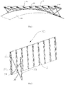
Fig. 1 is a schematic view of a flexible screen according to an embodiment of the present disclosure, wherein the flexible screen includes a flexible screen support device, the flexible screen is positioned in an arc form. -
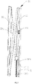
Fig. 2 is a schematic view of a portion of the flexible screen support device; wherein one second telescopic bracket of the flexible screen support device is expended. -
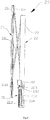
Fig. 3 is an exploded view of the second telescopic bracket shown inFig. 2 . -
Fig. 4 is another exploded view from another angle of the flexible screen support device shown inFig. 3 . -
Fig. 5 is a schematic assembly diagram of the second telescopic bracket of the flexible screen support device shown inFig. 2 . -
Fig. 6 is a schematic view of the first telescopic bracket of the flexible screen support device shown inFig. 1 . -
Fig. 7 is a schematic view of the flexible screen support device shown inFig. 2 , wherein the second telescopic bracket is contracted. -
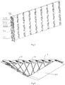
Figs. 8 and9 are schematic views of the flexible screen of the present disclosure shown inFig. 1 , wherein states of the flexible screen are changed by the flexible screen support device. -
Fig. 10 is a schematic view of a flexible screen support device according to a second embodiment of the present disclosure, wherein the flexible screen support device includes a flexible screen. - The following is a clear and complete description of the technical solution of the embodiments of the present disclosure, with reference to the drawings of the embodiments of the present disclosure.
- Referring to
Fig. 1 , a flexiblescreen support device 100 for supporting aflexible screen 200 is provided in an embodiment of the present disclosure. The flexiblescreen support device 100 includes asupport plate 10, a firsttelescopic bracket 20, and a plurality of secondtelescopic brackets 30 locating on two opposite sides of the firsttelescopic bracket 20. The firsttelescopic bracket 20 and the plurality of secondtelescopic brackets 30 couple thesupport plate 10 and theflexible screen 200. The firsttelescopic bracket 20 and the plurality of secondtelescopic brackets 30 drive theflexible screen 200 to form a curved surface. The curved surface includes wave-shaped curved surface, arc-shaped curved surface, convex surfaces with angle defined therebetween or concave surface with angles defined therebetween, and the curved surface can also be replaced by flat surface. - Further, the plurality of second
telescopic brackets 30 can rotate relative to a surface of thesupport plate 10. - Further, as shown in
Figs. 5 and6 , the firsttelescopic bracket 20 couples adriving unit 25, and each of the plurality of secondtelescopic brackets 30 couples adriving unit 31. - Specifically, in an exemplarily embodiment, the
driving unit 25 and thedriving units 31 have the same structure. Thedriving unit 31 includes adriving motor 311, ascrew rod 313 coupling thedriving motor 311, and adriving block 314 sleeving on thescrew rod 313. Thescrew rod 313 drives thedriving block 314 to enable the second telescopic bracket 30to expand or contract. Thedriving unit 25 includes adriving motor 251, ascrew rod 253 coupling thedriving motor 251, and adriving block 254 sleeving on thescrew rod 253. Thescrew rod 253 drives thedriving block 254 to enable the firsttelescopic bracket 20 to expand or contract. - Referring to
Fig. 2 , thesupport plate 10 is a rectangular plate. A plurality ofassembly slots 11 are defined on one side of thesupport plate 10 and are spaced from each other. In one embodiment, the plurality ofassembly slots 11 is strip-shaped. Theassembly slots 11 configure to receive thedriving unit 25 of the firsttelescopic bracket 20 and thedriving units 31 of the plurality of secondtelescopic brackets 30. In one embodiment,thedriving unit 25 of the firsttelescopic bracket 20 receives in one of the plurality ofassembly slots 11 which locates at the middle. - Further referring to
Figs. 3 , and4 , one of the plurality of secondtelescopic bracket 30 is illustrated as an example. Thedriving motor 311 of thedriving unit 31 receives in theassembly slot 11, thescrew rod 313 receives in thesame assembly slot 11 along a length direction thereof, and thedriving block 314 receives in one end of thesame assembly slot 11. - The second
telescopic bracket 30 includes afirst assembly plate 32, asecond assembly plate 33 and twosupport rod 34. Two ends of eachsupport rod 34 slidably arranges on thefirst assembly plate 32 and thesecond assembly plate 33 respectively. The two support rods 34 couple each other in a cross way and can rotate relative to each other. Center portions of the twosupport rods 34 couple together by a shaft, then the twosupport rods 34 can rotate relative to each other. One of the twosupport rods 34 includes a first end 341 and a second end 342 opposite to the first end 341. - The
first assembly plate 32 includes amain assembly board 321 and a first rotatingboard 322. The first rotatingboard 322 rotatably arranges on themain assembly board 321 through a rotatingshaft 35. Themain assembly board 321 is a strip-shaped board. Afirst assembly groove 324, a plurality ofsecond assembly grooves 3211 and a plurality ofassembly blocks 3212 are defined in themain assembly board 321, along a length direction thereof. In this embodiment, there are threesecond assembly grooves 3211. Eachassembly block 3212 is positioned between each twosecond assembly grooves 3211. Thefirst assembly groove 324 is spaced from asecond assembly groove 3211. The three second assembly grooves 3211 and the assembly blocks 3212 communicates with each other through axle holes. Two hinged ends 3221respectively arrange on two ends of one side of the first rotatingboard 322 and are spaced from each other. Twoassembly cylinders 3221 convexly arranges between the twohinged ends 3221 and are spaced from each other. - The first rotating
board 322 installs on themain assembly board 321. The twoassembly cylinders 3221 insert into the twosecond assembly grooves 3211, and the two assembly cylinders 3222 locates between the twoassembly blocks 3212. The rotatingshaft 35 passes through thefirst assembly groove 324, the plurality ofsecond assembly grooves 3211, the twoassembly cylinders 3221 and the plurality of assembly blocks 3212. Two ends of therotating shaft 35 are rotatably limited by the two hinged ends 3221. Themain assembly board 321 and the firstrotating board 322 rotatably connect. Thefirst assembly groove 324 is defined to be a limiting area, one portion of therotating shaft 35 received in thefirst assembly groove 32 is defined to be a first section and other portion of therotating shaft 35 is defined to be a second section. - A pushing
member 325 sleeves on the first section of therotating shaft 35, and the pushingmember 325 can slide along an axial direction of therotating shaft 35. The pushingmember 325 couples the drivingblock 314 and an end of one of the twosupport rods 34. The pushingmember 325 drives thesupport rod 34 to slide along thefirst assembly plate 32. One end of each of the twosupport rods 34 couples the firstrotating board 322. Two ends of the twosupport rods 34 coupled to the firstrotating board 322 are spaced from each other. The end of the onesupport rod 34 coupling the pushingmember 325 is driven by the pushingmember 325 to slidably move on the firstrotating board 322, along the axial direction of therotating shaft 35. One end of the other support rod 34is fixed on an end of the firstrotating board 322 that is away from the first section . - The driving
block 314 includes acoupling end 3141 in an arc shape. The pushingmember 325 includes acoupling slot 3251 in an arc shape. Thecoupling end 3141 inserts into thecoupling slot 3251, thus the pushingmember 325 can drive the drivingblock 314 to rotate around the rotatingshaft 35, thus avoiding the drivingblock 314 obstructing the rotation of the pushingmember 325. The pushingmember 325 includes acoupling end 3252 coupling the end 341 of thesupport rod 34 which slidably couples to the firstrotating board 322. - The
second assembly plate 33 includes amain coupling plate 331 and a secondrotating board 332. The secondrotating board 332 rotatably installs on themain coupling plate 331 through arotating shaft 333. The other end of each of the twosupport rods 34 couple the secondrotating board 332. Two ends of the twosupport rods 34 the secondrotating board 332 are spaced from each other.Themain coupling plate 331 and the secondrotating board 332 combined together are equivalent to a hinge structure. - Referring to
Figs. 5 ,2 and7 , a second slidingslot 334 is defined on each of two opposite ends of the secondrotating board 332. A first slidingslot 326 is defined on each of two opposite ends of the firstrotating board 322. The twosupport rods 34 couple each other in a cross way (as X-shaped), and then configure between thefirst assembly plate 32 and thesecond assembly plate 33, and couple thefirst assembly plate 32 and thesecond assembly plate 33. The first slidingslot 326 faces to the second slidingslot 334 . One end of the pushingmember 325 can slidably move along the first slidingslots 326. The two ends of onesupport rod 34 coupling the pushingmember 325 respectively and slidably receives in one first slidingslot 326 and one second slidingslot 334. Two ends of theother support rods 34 respectively receives in the other first slidingslot 326 and the other second slidingslot 334,thus the twosupport rods 34 can be open or closed. Themain coupling board 331 configures to couple theflexible screen 200. Themain assembly board 321 couples one side of thesupport board 10 whereon theassembly slots 11 define. When the drivingblock 314 drives the pushingmember 325 to slide along the rotatingshaft 35, the pushingmember 325 pushes one end of onesupport rod 34 to slide along the first slidingslot 326 and pushes the other end of the onesupport rod 34 to slide along the second slidingslots 334, thereby thesupport rod 34 pushed by the pushingmember 325 is close to theother support rod 34, thesecond assembly plate 33 is pushed away from thefirst assembly plate 32, thus the second assembly bracket can be expanded. - Further, a
torsion spring 326 arranges on themain assembly board 321. Thetorsion spring 326 locates on the second section of therotating shaft 35. Specifically, thetorsion spring 326 sleeves on outside of one of theassembly cylinder 3221 and abuts against themain assembly board 321 and the firstrotating board 322. During the rotation of thesecond assembly plate 32 relative to thesupport plate 10 and the flexible screen, a torsion force of thetorsion spring 326 prevents the excessive swing of theflexible screen 200 driven by thesecond assembly plate 32. - Referring to
Fig. 6 , a structure of the firsttelescopic bracket 20 is substantially the same as that of the secondtelescopic bracket 30, the only difference is that the firsttelescopic bracket 20 can only extend and retract, and are unable to rotate relative to thesupport plate 10. Specifically, the firsttelescopic bracket 20 includes athird assembly plate 21, afourth assembly plate 22, and twosupport rods 24 . Two ends of each of the twosupport rod 24 slidably arrange on thethird assembly plate 21 and thefourth assembly plate 22, respectively. The twosupport rods 24 couple each other in a cross way and can rotate relative to each other. - The
third assembly plate 21 includes amain assembly board 211 and a thirdrotating board 212 rotatably arranges on themain assembly board 211 through a rotating shaft 213. Thefourth assembly plate 22 includes amain coupling plate 221 and a fourthrotating board 223 rotatably arranging on themain coupling plate 221 through arotating shaft 222. One end of each of the twosupport rods 24 slidably couples the thirdrotating board 212. The ends of the twosupport rods 24 slidably coupled to the thirdrotating board 212 are spaced from each other. The other end of each of the twosupport rods 24 slidably couples the fourthrotating board 223. The ends of the twosupport rods 24 slidably coupled to the fourthrotating board 223 are spaced from each other. The twosupport rods 24 rotatably couple each other by a cross way. - Further, a slider 224 arranges on the
rotating shaft 222. The slider 224 couples the driving block 214 and an end of one of the twosupport rods 24, and the slider 224 drives thesupport rods 24 to slide along thefourth assembly plate 22. A third slidingslot 2121 is defined on one end of the thirdrotating board 212. A fourth sliding slot (not shown) is defined on one end of the fourthrotating board 223. The two support rods24 couple each other in a cross way (as X-shaped), and then the twosupport rods 24 configures between thethird assembly plate 21 and thefourth assembly plate 22, and couples thethird assembly plate 21 and thefourth assembly plate 22. The third slidingslot 2121 faces to the fourth sliding slot. One end of the slider 224 can slidably move along the fourth sliding slot. The two ends of onesupport rod 24 coupling the slider 224 respectively slidably receives in the third sliding slot and the fourth slidingslot 2121. Themain assembly board 211 configures to couple thesupport board 10. Themain coupling board 221 configures to couple theflexible screen 200. - Referring to
Fig. 10 , in another embodiment of the present disclosure, the driving units are a piston cylinder. The driving unit of the firsttelescopic bracket 20 includes a pushingrod 41 of the cylinder and acoupling block 42 coupling the pushingrod 41. The driving unit of each of the secondtelescopic brackets 30 includes a pushingrod 41 of the cylinder and a flexiblemovable block 43 coupling the pushingrod 41. The flexible screen is support by thecoupling block 42 and the flexiblemovable block 43. The flexiblemovable block 43 is made of elastic and deformable material, and when the flexible screen is curved, the flexible movable block43 can slow down the inclining force of the plurality of the secondtelescopic brackets 30 toward the firsttelescopic bracket 20. - Further, the flexible
screen support device 100 includes a control device which drives the firsttelescopic bracket 20 and the plurality of secondtelescopic brackets 30 to move. - When the flexible
screen support device 100 is driven by the control device, theflexible screen 200 transforms into a reset shape, as shown inFigs. 1 ,8 and9 , for example, a shape of theflexible screen 200 transforms into a concave arc-shape, and the driving unit of the firsttelescopic bracket 20 located in a middle position drives thesupport rod 24 to slide away from the other support rod , thus a value of an angle between the two support rods increases to maximum, and thethird assembly plate 21 and thefourth assembly plate 22 are relatively closed to each other. Further, a distance between a portion of theflexible screen 200 coupling the firsttelescopic bracket 20 and thesupport plate 10 is shortened. Then the secondtelescopic brackets 30 located on two opposite sides of the firsttelescopic bracket 20 are sequentially extended relative to thesupport plate 10, and extending lengths of the secondtelescopic brackets 30 are sequentially grow and are greater than the length of the firsttelescopic bracket 20. The secondtelescopic bracket 30 driven by the driving unit drives the pushingmember 325 to slide along the firstrotating shaft 35 in the limiting area, and further pushes thesupport rods 34 coupling the pushing member to slide along the first slidingslot 326 and the second slidingslot 334, thus the twosupport rods 34 can be opened or closed, further, the secondtelescopic bracket 30 can be contracted or expanded. In this process, the plurality of secondtelescopic brackets 30 suffer pulling force caused by thesupport plate 10 and theflexible screen 200. In order to prevent the damage of the flexible screen and realized the deformation of the flexible screen to be the curved surface, the firstrotating board 322 of eachfirst assembly plate 31 drives onesupport rods 34 to rotate relative to themain assembly board 331, while the secondrotating board 332 of eachsecond assembly plate 33 drives themain coupling plate 331 to rotate, thus an angle between each of the plurality of secondtelescopic brackets 30 is changed along with the deformation of theflexible screen 200; meanwhile, the firsttelescopic bracket 20 is fixed relative to thesupport plate 10 to avoid rotating, thus other secondtelescopic brackets 30 may have a stable supporting point when the shape of the flexible screen 200changes. - The flexible
screen support device 100 described in present disclosure couples thesupport plate 10 and theflexible screen 200 through the firsttelescopic bracket 20 and a plurality of secondtelescopic brackets 30. The expansion and contraction of the firsttelescopic bracket 20 and a plurality of secondtelescopic brackets 30 in different degrees drive theflexible screen 200 to form a curved surface, thus theflexible screen 200 can have diversified display modes.
Claims (19)
- A flexible screen support device, configuring for supporting a flexible screen, comprising:a support plate;a first telescopic bracket; anda plurality of second telescopic brackets locating on two opposite sides of the first telescopic bracket;wherein the first telescopic bracket and the plurality of second telescopic brackets couple the support plate and the flexible screen;wherein the first telescopic bracket and the plurality of second telescopic brackets drive the flexible screen to form a curved surface.
- The flexible screen support device of claim 1, wherein the first telescopic bracket couples a driving unit, and each of the plurality of second telescopic brackets couples a driving unit; wherein each of the driving unit comprises a driving motor, a screw rod coupling the driving motor, and a driving block sleeving on the screw rod; wherein the screw rod drives the driving block to expand and retract the second telescopic bracket.
- The flexible screen support device of claim 2, wherein the plurality of second telescopic brackets rotate relative to a surface of the support plate.
- The flexible screen support device of claim 3, wherein each of the second telescopic brackets comprises a first assembly plate, a second assembly plate and two support rods; two ends of each support rod are slidably arranged on the first assembly plate and the second assembly plate respectively; wherein the two support rods couple each other in a cross way and rotate relative to each other.
- The flexible screen support device of claim 4, wherein a rotating shaft and a pushing member arrange on the first assembly plate; wherein the pushing member rotatably sleeves on the rotating shaft and slides along the rotating shaft; wherein the first pushing member couples the driving block and an end of one of the two support rods; wherein the first pushing member drives the support rod to slide along the first assembly plate.
- The flexible screen support device of claim 5, wherein the first assembly plate comprises a main assembly board and a first rotating board rotatably arranging on the main assembly board through the rotating shaft; wherein an end of each of the two support rods couples the first rotating board, the ends of the two support rods coupling the first rotating board are spaced from each other; wherein the end of the one support rod coupling the pushing member slidably moves on the first rotating board along an axial direction of the rotating shaft.
- The flexible screen support device of claim 6, wherein the first rotating shaft arranges on the main assembly board, and comprises a first section and a second section; wherein the pushing member sleeves on the first section of the rotating shaft; wherein a limiting area is defined on the first rotating board and the first section locates therein.
- The flexible screen support device of claim 7, wherein a torsion spring arranges on the main assembly board, locates on the second section of the first rotating shaft, and abuts against the main assembly board and the first rotating board.
- The flexible screen support device of claim6, wherein the second assembly plate comprises a main coupling plate and a second rotating board rotatably installing on the main coupling plate through a rotating shaft; wherein the other end of each of the two support rods couple the second rotating board; two ends of the two support rods connected to the second rotating board are spaced from each other.
- The flexible screen support device of claim 4, wherein center portions of the two support rods couple together by a shaft.
- The flexible screen support device of claim 9, wherein a first sliding slot is defined on each of two opposite ends of the first rotating board, and a second sliding slot is defined on each of two opposite ends of the second rotating board; wherein the two ends of one support rod coupling the pushing member respectively and slidably receives in one first sliding slot, and one second sliding slot.
- The flexible screen support device of claim 5, wherein the driving block comprises a coupling end in arc shape and the pushing member comprises a coupling slot in arc shape; wherein the coupling end inserts into the coupling slot, and the pushing member drives the driving block to rotate around the first rotating shaft.
- The flexible screen support device of claim 3, wherein the first telescopic bracket comprises a third assembly plate, a fourth assembly plate, and two support rods; two ends of each of the two support rod are slidably arranged on the third assembly plate and the fourth assembly plate, respectively; the two support rods couple each other in a cross way and rotate relative to each other.
- The flexible screen support device of claim 13, wherein the third assembly plate comprises a main assembly board and a third rotating board rotatably arranging on the main assembly board through a rotating shaft, and, the fourth assembly plate comprises a main coupling plate and a fourth rotating board rotatably arranging on the main coupling plate through a rotating shaft; wherein one end of each of the two support rods slidably couples the third rotating board; the ends of the two support rods slidably coupling the third rotating board are spaced from each other; the other end of each of the two support rods slidably couples the fourth rotating board; the ends of the two support rods slidably coupling the fourth rotating board are spaced from each other.
- The flexible screen support device of claim 14, wherein a slider arranges on the rotating shaft, the slider couples the driving block and the end of one of the two support rods, and drives the support rods to slide along the third assembly plate.
- The flexible screen support device of claim 15, wherein the rotating shaft arranges on the main assembly coupling board and comprises a first section and a second section spaced from the first section; wherein the pushing member sleeves on the first section; wherein a limiting area is defined on the first rotating board; wherein the first section locates in the limiting area and couples two opposite walls of the assembly slot.
- The flexible screen support device of claim 2, wherein the driving units are piston cylinders; the driving unit of the first telescopic bracket comprises a pushing rod of the cylinder and a coupling block coupling the pushing rod, and the driving unit of the second telescopic bracket comprises a pushing rod of the cylinder and a flexible movable block coupling the pushing rod; wherein the flexible screen is support by the coupling block and the flexible movable block.
- The flexible screen support device of claim 1, further comprising a control device which drives the first telescopic bracket and the plurality of second telescopic brackets to move.
- A flexible screen, comprising a display surface, a back surface, and a flexible screen support device of any one of claim 1 to claim 18; wherein the flexible screen support device couples the back surface.
Applications Claiming Priority (1)
| Application Number | Priority Date | Filing Date | Title |
|---|---|---|---|
| PCT/CN2016/100729 WO2018058404A1 (en) | 2016-09-29 | 2016-09-29 | Flexible screen support device and flexible screen |
Publications (2)
| Publication Number | Publication Date |
|---|---|
| EP3522139A1 true EP3522139A1 (en) | 2019-08-07 |
| EP3522139A4 EP3522139A4 (en) | 2020-04-01 |
Family
ID=61643777
Family Applications (1)
| Application Number | Title | Priority Date | Filing Date |
|---|---|---|---|
| EP16917158.4A Withdrawn EP3522139A4 (en) | 2016-09-29 | 2016-09-29 | Flexible screen support device and flexible screen |
Country Status (7)
| Country | Link |
|---|---|
| US (1) | US10753528B2 (en) |
| EP (1) | EP3522139A4 (en) |
| JP (1) | JP2019530897A (en) |
| KR (1) | KR20190043613A (en) |
| CN (1) | CN107835914B (en) |
| CA (1) | CA3038826A1 (en) |
| WO (1) | WO2018058404A1 (en) |
Families Citing this family (27)
| Publication number | Priority date | Publication date | Assignee | Title |
|---|---|---|---|---|
| CN108447412B (en) * | 2018-05-30 | 2024-05-31 | 深圳市优景观复光电有限公司 | Curved surface structure LED display device and curved surface LED large screen display |
| CN109058725B (en) * | 2018-09-14 | 2021-07-09 | 武汉天马微电子有限公司 | Support assembly and display device |
| KR102540136B1 (en) * | 2018-09-21 | 2023-06-02 | 엘지디스플레이 주식회사 | Rollable display device |
| CN109210343B (en) * | 2018-11-02 | 2023-10-20 | 利亚德光电股份有限公司 | Triaxial connecting piece for mirror-face backdrop LED display screen |
| CN111326070B (en) * | 2018-12-17 | 2022-02-22 | 上海和辉光电股份有限公司 | Flexible display device and mobile terminal |
| US12031663B1 (en) * | 2019-02-25 | 2024-07-09 | Russ Bassett Corporation | Array with lateral movement |
| CN110293913A (en) * | 2019-07-12 | 2019-10-01 | 刘超 | A kind of novel HUD new line display flexible folding screen |
| CN110675759B (en) | 2019-09-25 | 2021-11-02 | 武汉华星光电半导体显示技术有限公司 | Vertical OLED display device |
| CN110701385B (en) * | 2019-10-10 | 2021-12-17 | 南通国盛精密机械有限公司 | High-strength combined type rack |
| CN211118419U (en) * | 2019-12-04 | 2020-07-28 | 京东方科技集团股份有限公司 | Display device and its supporting structure |
| CN111009190B (en) * | 2019-12-18 | 2021-02-02 | 武汉华星光电半导体显示技术有限公司 | Foldable display device |
| KR20220008593A (en) * | 2020-07-14 | 2022-01-21 | 엘지디스플레이 주식회사 | Display apparatus |
| TWI740617B (en) * | 2020-08-19 | 2021-09-21 | 智崴資訊科技股份有限公司 | Curved display module |
| CN111951686A (en) * | 2020-08-26 | 2020-11-17 | 京东方科技集团股份有限公司 | Flexible display panel attachment device |
| CN113035060B (en) * | 2021-02-25 | 2022-08-16 | 昆山国显光电有限公司 | Flexible display device and driving apparatus |
| CN113163042B (en) * | 2021-05-27 | 2023-03-31 | 维沃移动通信有限公司 | Electronic device |
| CN113347294A (en) * | 2021-06-17 | 2021-09-03 | Oppo广东移动通信有限公司 | Electronic equipment and linkage mechanism thereof |
| CN113554925B (en) * | 2021-07-22 | 2022-11-15 | 山东东方信达信息科技股份有限公司 | Cloud control intelligent home display model convenient to demonstrate |
| CN113570974B (en) * | 2021-08-11 | 2022-07-08 | 闻泰通讯股份有限公司 | Flexible screen telescopic structure and electronic equipment |
| CN113672096B (en) * | 2021-09-17 | 2025-02-11 | 深圳申鲲科技有限公司 | An intelligent gesture interactive display device with holographic effect |
| CN114484186B (en) * | 2022-02-22 | 2024-05-17 | 上海天马微电子有限公司 | Display device and carrier |
| CN114980637B (en) * | 2022-04-26 | 2024-03-22 | 维沃移动通信有限公司 | Electronic equipment |
| KR102507176B1 (en) * | 2022-07-01 | 2023-03-08 | 메타모빌리티 주식회사 | Sliding type variable screen |
| CN115527448A (en) * | 2022-09-29 | 2022-12-27 | 深圳市瑞丰光电子股份有限公司 | Flexible panel, display device and control system of flexible panel |
| CN115574225A (en) * | 2022-11-08 | 2023-01-06 | 长广溪智能制造(无锡)有限公司 | Adjusting device |
| CN115507270B (en) * | 2022-11-20 | 2023-02-21 | 成都大学 | Monitoring equipment for tunnel deformation |
| WO2025127194A1 (en) * | 2023-12-13 | 2025-06-19 | 엘지전자 주식회사 | Display device |
Family Cites Families (26)
| Publication number | Priority date | Publication date | Assignee | Title |
|---|---|---|---|---|
| US4372071A (en) * | 1981-09-14 | 1983-02-08 | Vicino Robert K | Fabric faced billboard |
| GB9222165D0 (en) * | 1992-10-22 | 1992-12-02 | Hanover Dispays Limited | A display device |
| JP2006023676A (en) | 2004-07-09 | 2006-01-26 | Pioneer Electronic Corp | Display-adjusting device and display device |
| US20080086816A1 (en) * | 2006-10-16 | 2008-04-17 | General Electric Company | Patient positioning system |
| JP2009047849A (en) | 2007-08-17 | 2009-03-05 | Seiko Epson Corp | screen |
| US20090159768A1 (en) * | 2007-12-20 | 2009-06-25 | Oh Sung I | Mount System Utilizing One Motor to Extend/Retract and Tilt a Monitor |
| US7779568B2 (en) * | 2008-03-17 | 2010-08-24 | Adaptive Micro Systems Llc | Adjustable LED sign mounting system |
| CN101712290B (en) * | 2009-08-18 | 2012-06-20 | 浙江吉利汽车研究院有限公司 | Automobile headrest |
| JP5484034B2 (en) | 2009-12-21 | 2014-05-07 | 広州美視晶瑩銀幕有限公司 | Screen device |
| KR101227644B1 (en) | 2010-08-10 | 2013-01-30 | 유상규 | Rollable flexible display device |
| FR2990031B1 (en) | 2012-04-27 | 2014-05-09 | Robert Miggiano | SCREEN PROJECTION SCREEN DEVICE |
| WO2014144956A2 (en) * | 2013-03-15 | 2014-09-18 | The Coca-Cola Company | Display devices |
| US10104963B2 (en) * | 2013-06-07 | 2018-10-23 | Milestone Av Technologies Llc | Wall mount system |
| CN103423564B (en) | 2013-07-26 | 2016-09-28 | 深圳市华美特科技有限公司 | Telescopic display panel mounting structure, spliced screen wall and control system |
| KR102315659B1 (en) | 2013-11-27 | 2021-10-20 | 가부시키가이샤 한도오따이 에네루기 켄큐쇼 | Display device |
| KR20160008995A (en) * | 2014-07-15 | 2016-01-25 | 씨제이씨지브이 주식회사 | Flexible Screen System |
| CN104238923B (en) * | 2014-07-29 | 2019-03-29 | 京东方科技集团股份有限公司 | A display device and its working method |
| CN104197240A (en) | 2014-08-19 | 2014-12-10 | 深圳市华星光电技术有限公司 | Curvature adjustable composite back board and backlight module |
| CN204537648U (en) | 2015-03-23 | 2015-08-05 | 洪海光电集团有限公司 | The concavo-convex LED display of program control staggered form |
| US9605439B2 (en) * | 2015-07-27 | 2017-03-28 | Ronald Young | Kitchen cabinet installation device |
| CN105118390B (en) | 2015-09-30 | 2017-08-01 | 京东方科技集团股份有限公司 | Back board structure and display device |
| CN105225614A (en) * | 2015-10-26 | 2016-01-06 | 京东方科技集团股份有限公司 | A kind of camber display screen curvature regulating device and using method, curved-surface display device |
| CN205136973U (en) | 2015-10-30 | 2016-04-06 | 西安科技大学 | Display wall mount arm bracket set with adjustable |
| TWM520666U (en) | 2015-11-10 | 2016-04-21 | 青輔實業股份有限公司 | Screen support device |
| KR101873026B1 (en) * | 2015-12-17 | 2018-07-02 | 한국전자통신연구원 | Camera rig apparatus for shooting multi-view image |
| US11657738B2 (en) * | 2017-01-18 | 2023-05-23 | Production Resource Group Llc | Foldable spaceframe and method of setting up spaceframe structure |
-
2016
- 2016-09-29 CA CA3038826A patent/CA3038826A1/en not_active Abandoned
- 2016-09-29 KR KR1020197009803A patent/KR20190043613A/en not_active Ceased
- 2016-09-29 JP JP2019515909A patent/JP2019530897A/en active Pending
- 2016-09-29 WO PCT/CN2016/100729 patent/WO2018058404A1/en not_active Ceased
- 2016-09-29 EP EP16917158.4A patent/EP3522139A4/en not_active Withdrawn
- 2016-09-29 CN CN201680031928.3A patent/CN107835914B/en not_active Expired - Fee Related
- 2016-09-29 US US16/337,986 patent/US10753528B2/en not_active Expired - Fee Related
Also Published As
| Publication number | Publication date |
|---|---|
| US20200025325A1 (en) | 2020-01-23 |
| WO2018058404A1 (en) | 2018-04-05 |
| CN107835914A (en) | 2018-03-23 |
| KR20190043613A (en) | 2019-04-26 |
| CN107835914B (en) | 2020-03-24 |
| US10753528B2 (en) | 2020-08-25 |
| CA3038826A1 (en) | 2018-04-05 |
| JP2019530897A (en) | 2019-10-24 |
| EP3522139A4 (en) | 2020-04-01 |
Similar Documents
| Publication | Publication Date | Title |
|---|---|---|
| US10753528B2 (en) | Flexible screen support device and flexible screen | |
| JP6907343B2 (en) | Flexible screen mobile terminal hinges and flexible screen mobile terminals | |
| KR102444383B1 (en) | Rotating shaft connection structure and collapsible device | |
| EP2421231B1 (en) | Mobile electronic device | |
| KR102034585B1 (en) | Display Device | |
| JP7058743B2 (en) | External flexible screens / hinges and hinge devices for mobile terminals | |
| WO2019153256A1 (en) | Flexible display apparatus | |
| WO2021007936A1 (en) | Linkage mechanism, folding device, and electronic device | |
| CN109495621A (en) | Folding mechanism and mobile terminal | |
| CN114338864A (en) | Folding device and electronic equipment | |
| KR20220002630A (en) | Hinge mechanism and foldable mobile terminal | |
| KR20210089769A (en) | Rotating shaft mechanism and mobile terminal | |
| WO2022042394A1 (en) | Telescopic mechanism and electronic device | |
| CN111176382A (en) | Screen and electronic equipment | |
| CN114046313A (en) | Hinge, display panel and electronic device | |
| JP2019506651A (en) | Foldable components and mobile devices | |
| US20170064844A1 (en) | Connection device applicable to flexible display screen | |
| CN107358874A (en) | A flexible display device | |
| WO2016101897A1 (en) | Flexible screen component and terminal | |
| TWM474324U (en) | Synchronous mechanism torque of biaxial hinge connector | |
| US11283911B2 (en) | Hinge, folding mechanism, and terminal device | |
| CN211857984U (en) | Support structure and foldable display device | |
| KR20250166039A (en) | Hinge system of portable device within flexible display | |
| CN111386420A (en) | Remote controller support and remote controller | |
| CN209313355U (en) | Multifunctional cable bridge |
Legal Events
| Date | Code | Title | Description |
|---|---|---|---|
| PUAI | Public reference made under article 153(3) epc to a published international application that has entered the european phase |
Free format text: ORIGINAL CODE: 0009012 |
|
| 17P | Request for examination filed |
Effective date: 20190417 |
|
| AK | Designated contracting states |
Kind code of ref document: A1 Designated state(s): AL AT BE BG CH CY CZ DE DK EE ES FI FR GB GR HR HU IE IS IT LI LT LU LV MC MK MT NL NO PL PT RO RS SE SI SK SM TR |
|
| AX | Request for extension of the european patent |
Extension state: BA ME |
|
| DAV | Request for validation of the european patent (deleted) | ||
| DAX | Request for extension of the european patent (deleted) | ||
| A4 | Supplementary search report drawn up and despatched |
Effective date: 20200303 |
|
| RIC1 | Information provided on ipc code assigned before grant |
Ipc: G09F 15/00 20060101ALI20200226BHEP Ipc: G09F 9/30 20060101AFI20200226BHEP |
|
| STAA | Information on the status of an ep patent application or granted ep patent |
Free format text: STATUS: THE APPLICATION HAS BEEN WITHDRAWN |
|
| 18W | Application withdrawn |
Effective date: 20200416 |