EP3521952A1 - Safety control unit, safety control method, and safety control program - Google Patents
Safety control unit, safety control method, and safety control program Download PDFInfo
- Publication number
- EP3521952A1 EP3521952A1 EP17855496.0A EP17855496A EP3521952A1 EP 3521952 A1 EP3521952 A1 EP 3521952A1 EP 17855496 A EP17855496 A EP 17855496A EP 3521952 A1 EP3521952 A1 EP 3521952A1
- Authority
- EP
- European Patent Office
- Prior art keywords
- control
- program
- safety
- computation
- data
- Prior art date
- Legal status (The legal status is an assumption and is not a legal conclusion. Google has not performed a legal analysis and makes no representation as to the accuracy of the status listed.)
- Granted
Links
Images

Classifications
-
- G—PHYSICS
- G05—CONTROLLING; REGULATING
- G05B—CONTROL OR REGULATING SYSTEMS IN GENERAL; FUNCTIONAL ELEMENTS OF SUCH SYSTEMS; MONITORING OR TESTING ARRANGEMENTS FOR SUCH SYSTEMS OR ELEMENTS
- G05B19/00—Program-control systems
- G05B19/02—Program-control systems electric
- G05B19/04—Program control other than numerical control, i.e. in sequence controllers or logic controllers
- G05B19/05—Programmable logic controllers, e.g. simulating logic interconnections of signals according to ladder diagrams or function charts
- G05B19/056—Programming the PLC
-
- G—PHYSICS
- G05—CONTROLLING; REGULATING
- G05B—CONTROL OR REGULATING SYSTEMS IN GENERAL; FUNCTIONAL ELEMENTS OF SUCH SYSTEMS; MONITORING OR TESTING ARRANGEMENTS FOR SUCH SYSTEMS OR ELEMENTS
- G05B9/00—Safety arrangements
- G05B9/02—Safety arrangements electric
-
- G—PHYSICS
- G05—CONTROLLING; REGULATING
- G05B—CONTROL OR REGULATING SYSTEMS IN GENERAL; FUNCTIONAL ELEMENTS OF SUCH SYSTEMS; MONITORING OR TESTING ARRANGEMENTS FOR SUCH SYSTEMS OR ELEMENTS
- G05B19/00—Program-control systems
- G05B19/02—Program-control systems electric
- G05B19/04—Program control other than numerical control, i.e. in sequence controllers or logic controllers
- G05B19/05—Programmable logic controllers, e.g. simulating logic interconnections of signals according to ladder diagrams or function charts
-
- G—PHYSICS
- G05—CONTROLLING; REGULATING
- G05B—CONTROL OR REGULATING SYSTEMS IN GENERAL; FUNCTIONAL ELEMENTS OF SUCH SYSTEMS; MONITORING OR TESTING ARRANGEMENTS FOR SUCH SYSTEMS OR ELEMENTS
- G05B19/00—Program-control systems
- G05B19/02—Program-control systems electric
- G05B19/418—Total factory control, i.e. centrally controlling a plurality of machines, e.g. direct or distributed numerical control [DNC], flexible manufacturing systems [FMS], integrated manufacturing systems [IMS] or computer integrated manufacturing [CIM]
-
- G—PHYSICS
- G05—CONTROLLING; REGULATING
- G05B—CONTROL OR REGULATING SYSTEMS IN GENERAL; FUNCTIONAL ELEMENTS OF SUCH SYSTEMS; MONITORING OR TESTING ARRANGEMENTS FOR SUCH SYSTEMS OR ELEMENTS
- G05B2219/00—Program-control systems
- G05B2219/10—Plc systems
- G05B2219/13—Plc programming
- G05B2219/13153—Modification, change of program in real time
-
- G—PHYSICS
- G05—CONTROLLING; REGULATING
- G05B—CONTROL OR REGULATING SYSTEMS IN GENERAL; FUNCTIONAL ELEMENTS OF SUCH SYSTEMS; MONITORING OR TESTING ARRANGEMENTS FOR SUCH SYSTEMS OR ELEMENTS
- G05B2219/00—Program-control systems
- G05B2219/10—Plc systems
- G05B2219/14—Plc safety
- G05B2219/14006—Safety, monitoring in general
-
- G—PHYSICS
- G05—CONTROLLING; REGULATING
- G05B—CONTROL OR REGULATING SYSTEMS IN GENERAL; FUNCTIONAL ELEMENTS OF SUCH SYSTEMS; MONITORING OR TESTING ARRANGEMENTS FOR SUCH SYSTEMS OR ELEMENTS
- G05B2219/00—Program-control systems
- G05B2219/10—Plc systems
- G05B2219/14—Plc safety
- G05B2219/14007—Plc as standalone for safety control of machine
Definitions
- the present invention relates to a safety control unit for FA systems, and a safety control technique in FA systems.
- a control unit performs batch conversion (data refresh) of control data including data for safety control, with respect to any external devices including the safety device. Specifically, after the control unit executes a series of programs for controlling the FA system, the control unit performs a data refresh and again executes the series of programs. The data for safety control is updated at the time of this data refresh. Then, the safety control in the safety control system is realized by repeating this process.
- Patent Document 1 JP 2009-9505A
- the conventional safety control units temporarily stop all programs including any data refresh. For this reason, the safety control unit can not input safety control data, and stops the external devices included in the FA system. That is, the safety control of the FA system stops.
- the present invention aims to provide a safety control unit and a safety control technique that can prevent an unnecessary stop due to safety control, for example, at a time when a program is changed.
- a safety control unit includes: a memory that stores a system program for safety control, a control program for safety control, and a control data; a computation control part configured to execute safety control using the control data, the system program, and the control program; and an input and output unit for connecting the computation control part to a safety input device and an output device to be safely controlled.
- the system program includes a data refresh program for executing a data refresh of safety control data of the safety input device and the output device and the control data of the memory via the input and output unit. If the computation control part receives a change of the control program, the computation control part stops executing the control program. The computation control part executes the change of the control program while executing a part of the system program including the data refresh. The computation control part resumes the execution the control program.
- an unnecessary stop of the safety control can be prevented, for example, at a time when a program is changed.
- Fig. 1 is a block diagram showing a schematic configuration of a safety control system including a safety control unit according to the embodiment of the present invention.
- Fig. 2 is a diagram showing configurations of a system program and a control program.
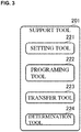
- Fig. 3 is a diagram showing a configuration of a support tool.
- a safety control unit 10 is connected to a PC (personal computer) 20, a safety input device 31, and an output device 32.
- the safety control unit 10, the safety input device 31, and the output device 32 are connected through a predetermined data network. Note, that it is preferable that this data network is constituted with protocols with high connection reliability.
- the safety control unit 10, the safety input device 31, and the output device 32 realize a safety control system using an FA (Factory Automation) system. Note, that a general input device may be connected to this safety control system.
- the safety input device 31 is a device for obtaining data for safety control, such as a light curtain or a safety switch.
- the output device 32 executes operations regarding safety control through relays, motors, lamps, and the like of the FA system. Note, that one safety input device 31 and one output device 32 are shown in Fig. 1 , but multiple safety input devices 31 may be arranged and multiple output devices 32 may be arranged.
- the safety control unit 10 and the PC 20 are locally connected via, for example, a general data communication cable.
- a support tool 201 is incorporated in the PC 20.
- the safety control unit 10 downloads programs and setting information that are created using the support tool 201.
- the safety control unit 10 includes a computation control part 101, a memory 102, and an input and output unit 103.
- the computation control part 101 is connected to the memory 102 and the input and output unit 103.
- the input and output unit 103 is connected to the safety input device 31 and the output device 32 via the above-mentioned data network.
- the memory 102 stores a system program 120S, a control program 120C, and control data 120D.
- the system program 120S has a scheduler program 121, a data refresh program 122, a motion computation program 123, and a sequence command computation program 124.
- the control program 120C has the sequence command computation program 124 and a user program 125.
- the control data 120D is referred to when the system program 120S and the control program 120C are executed.
- a safety control continuation setting variable 120R is a variable in which whether to continue safety control when the control data 120 D is rewritten is set, that is, whether to continue data refresh is set.
- the scheduler program 121 manages the schedules of various processes that the computation control part 101 executes.
- the data refresh program 122 performs batch conversion of the safety control data stored in the control data 120D in the memory 102 and the input and output unit 103, and performs batch conversion of the safety control data stored in the control data 120D in the memory 102 and the safety input device 31 and the output device 32 via the input and output unit 103. More specifically, the data refresh program 122 executes the process for reflecting the safety control data from the safety input device 31 in the control data 120D via the input and output unit 103, and executes the process for outputting output data for safety control and computation results from the motion computation program 123 and the user program 125 to the output device 32 via the input and output unit 103. Note, that the output data for safety control is used for controlling the states of the output device 32, based on input data for safety control.
- the motion computation program 123 performs computations for controlling motion devices such as motors (e.g., servo motors), based on data that a general input device obtains.
- motors e.g., servo motors
- the sequence command computation program 124 belongs to the system program 120S and the control program 120C, and is a program based on the ladder diagram for safety control that is created by the support tool 201.
- the user program 125 executes various settings for safety control created by the support tool 201.
- the computation control part 101 continuously executes the system program 120S and the control program 120C, while referring to the control data 120D. Specifically, based on the scheduler program 121, the computation control part 101 executes the motion computation program 123, the sequence command computation program 124, and the user program 125. At this time, the computation control part 101 refers to the control data 120D.
- the computation control part 101 executes the data refresh program 122. Specifically, the computation control part 101 performs, using the data refresh program 122, batch conversion of the control data 120D in the memory 102 and the safety control data of the safety input device 31 and the output device 32 via the input and output unit 103.
- the computation control part 101 Upon completion of the data refresh, the computation control part 101 executes the motion computation program 123, the sequence command computation program 124, and the user program 125 with reference to the control data 120D subjected to the data conversion.
- the safety control of the FA system is realized by the computation control part 101 repeating this series of processes.
- the support tool 201 has a setting tool 221, a programing tool 222, a transfer tool 223, and a determination tool 224.
- the setting tool 221 is used for creating the user program 125 including the above-mentioned various settings.
- the programing tool is used for creating a ladder diagram, in other words, is used for creating the sequence command computation program 124.
- the transfer tool 223 is used for converting the user program 125 created by the setting tool 221 and the sequence command computation program 124 created by the programing tool 222 into the data format to be transferred to the computation control part 101, and is used for transferring these data.
- the determination tool 224 is used for determining whether the safety control needs to be stopped, that is, whether the data refresh needs to be stopped when the user program 125 and the sequence command computation program 124 are transferred.
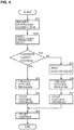
- Fig. 4 is a flowchart of a safety control process in the computation control part.
- the computation control part 101 receives an instruction for rewriting the user program 125 and the sequence command computation program 124, that is, a download instruction (S11). While the computation control part 101 receives no download instruction, the computation control part 101 continuously executes, as mentioned above, the system program 120S including the data refresh and the control using the control program 120C, while referring to the control data 120D.
- a download instruction S11
- the computation control part 101 refers to the download instruction, and detects whether to change the control program 120C while continuing the safety control (S101).
- the computation control part 101 stops executing the control program 120C, and unloads the control program 120C (S13). At this time, the computation control part 101 continuously executes a part of the system program 120S including the data refresh program 122 without stopping the execution, except for the sequence command computation program 124.
- the computation control part 101 loads the control program 120C (the sequence command computation program 124 and the user program 125) that is downloaded from the support tool 201 (S14). At this time, the computation control part 101 continuously executes a part of the system program 120S including the data refresh program 122 without stopping the execution, except for the sequence command computation program 124.
- the safety control unit 10 can change the control program 120C without temporarily stopping the data refresh. In this manner, an unnecessary temporary stop of the safety control can be prevented.
- the computation control part 101 stops executing the data refresh program 122 (S15). That is, the computation control part 101 stops safety communication to the devices related to the safety control. After that, the computation control part 101 unloads the control program 120C (S16), and loads the control program 120C that is downloaded from the support tool 201 (S17). Then, the computation control part 101 resumes executing the system program 120S and the control program 120C (S18).
- an administrator and the like of the FA system can select whether the change of the system program 120S and the control program 120C with the stop of the safety control is needed.
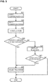
- Fig. 5 is a flowchart of a program change process in the support tool.
- the support tool 201 receives an input of a ladder diagram including a safety control process from a programmer using the programing tool 222 (S21). Also, the support tool 201 receives an input regarding various settings for safety control from a programmer using the setting tool 221 (S22).
- the control program 120C is created, which has the sequence command computation program 124 and the user program 125, and includes safety control. Note, that the order of step S21 and step S22 is not limited to this order, and may be reversed.
- the support tool 201 collates, using the determination tool 224, the program that is created and changed by the support tool 201 and the program that is stored in the memory 102 of the safety control unit 10 (S23).
- the support tool 201 determines, using the determination tool 224, whether the stop of the safety control is needed when the control program 120C is changed.
- the support tool 201 starts transferring the control program 120C (the sequence command computation program 124 and the user program 125) using the transfer tool 223 (S25).
- the support tool 201 displays a warning on the display of the PC 20 or the like (S26).
- the support tool 201 If the support tool 201 receives an operation input for transferring from a programmer (YES in S27), the support tool 201 starts transferring the control program 120C (S25). On the other hand, if the support tool 201 receives no operation input for transferring from the programmer (NO in S27), the support tool 201 ends the process.
Landscapes
- Engineering & Computer Science (AREA)
- Physics & Mathematics (AREA)
- General Physics & Mathematics (AREA)
- Automation & Control Theory (AREA)
- General Engineering & Computer Science (AREA)
- Manufacturing & Machinery (AREA)
- Quality & Reliability (AREA)
- Programmable Controllers (AREA)
- Stored Programmes (AREA)
Abstract
Description
- The present invention relates to a safety control unit for FA systems, and a safety control technique in FA systems.
- Currently, many FA (Factory Automation) systems are used.
- As described in Patent Document 1, external devices of an FA system are controlled by a control unit (programmable logic controller). With such a configuration of the FA system, a safety control system that uses a safety device as an external device can also be constituted.
- In such a safety control system, a control unit (safety control unit) performs batch conversion (data refresh) of control data including data for safety control, with respect to any external devices including the safety device. Specifically, after the control unit executes a series of programs for controlling the FA system, the control unit performs a data refresh and again executes the series of programs. The data for safety control is updated at the time of this data refresh. Then, the safety control in the safety control system is realized by repeating this process.
- Patent Document 1:
JP 2009-9505A - However, if conventional safety control units are subject to a program change from the outside, the conventional safety control units temporarily stop all programs including any data refresh. For this reason, the safety control unit can not input safety control data, and stops the external devices included in the FA system. That is, the safety control of the FA system stops.
- Accordingly, the present invention aims to provide a safety control unit and a safety control technique that can prevent an unnecessary stop due to safety control, for example, at a time when a program is changed.
- A safety control unit according to the present invention includes: a memory that stores a system program for safety control, a control program for safety control, and a control data; a computation control part configured to execute safety control using the control data, the system program, and the control program; and an input and output unit for connecting the computation control part to a safety input device and an output device to be safely controlled. The system program includes a data refresh program for executing a data refresh of safety control data of the safety input device and the output device and the control data of the memory via the input and output unit. If the computation control part receives a change of the control program, the computation control part stops executing the control program. The computation control part executes the change of the control program while executing a part of the system program including the data refresh. The computation control part resumes the execution the control program.
- In this configuration, because the data refresh is continued when the control program is changed, the safety control is continued.
- According to the present invention, an unnecessary stop of the safety control can be prevented, for example, at a time when a program is changed.
-
-
Fig. 1 is a block diagram showing a schematic configuration of a safety control system including a control unit according to an embodiment of the present invention. -
Fig. 2 is a diagram showing configurations of a system program and a control program. -
Fig. 3 is a diagram showing a configuration of a support tool. -
Fig. 4 is a flowchart of a safety control process in a computation control part. -
Fig. 5 is a flowchart of a program change process in the support tool. - A safety control unit and a data safety control technique according to an embodiment of the present invention will be described with reference to the drawings.
Fig. 1 is a block diagram showing a schematic configuration of a safety control system including a safety control unit according to the embodiment of the present invention.Fig. 2 is a diagram showing configurations of a system program and a control program.Fig. 3 is a diagram showing a configuration of a support tool. - As shown in
Fig. 1 , asafety control unit 10 is connected to a PC (personal computer) 20, asafety input device 31, and anoutput device 32. Thesafety control unit 10, thesafety input device 31, and theoutput device 32 are connected through a predetermined data network. Note, that it is preferable that this data network is constituted with protocols with high connection reliability. Thesafety control unit 10, thesafety input device 31, and theoutput device 32 realize a safety control system using an FA (Factory Automation) system. Note, that a general input device may be connected to this safety control system. - The
safety input device 31 is a device for obtaining data for safety control, such as a light curtain or a safety switch. Theoutput device 32 executes operations regarding safety control through relays, motors, lamps, and the like of the FA system. Note, that onesafety input device 31 and oneoutput device 32 are shown inFig. 1 , but multiplesafety input devices 31 may be arranged andmultiple output devices 32 may be arranged. - The
safety control unit 10 and the PC 20 are locally connected via, for example, a general data communication cable. Asupport tool 201 is incorporated in the PC 20. Thesafety control unit 10 downloads programs and setting information that are created using thesupport tool 201. - The
safety control unit 10 includes acomputation control part 101, amemory 102, and an input andoutput unit 103. - The
computation control part 101 is connected to thememory 102 and the input andoutput unit 103. The input andoutput unit 103 is connected to thesafety input device 31 and theoutput device 32 via the above-mentioned data network. - As shown in
Fig. 1 , thememory 102 stores asystem program 120S, acontrol program 120C, andcontrol data 120D. As shown inFig. 2 , thesystem program 120S has ascheduler program 121, adata refresh program 122, amotion computation program 123, and a sequencecommand computation program 124. Thecontrol program 120C has the sequencecommand computation program 124 and auser program 125. - The
control data 120D is referred to when thesystem program 120S and thecontrol program 120C are executed. A safety control continuation setting variable 120R is a variable in which whether to continue safety control when thecontrol data 120 D is rewritten is set, that is, whether to continue data refresh is set. - The
scheduler program 121 manages the schedules of various processes that thecomputation control part 101 executes. - The
data refresh program 122 performs batch conversion of the safety control data stored in thecontrol data 120D in thememory 102 and the input andoutput unit 103, and performs batch conversion of the safety control data stored in thecontrol data 120D in thememory 102 and thesafety input device 31 and theoutput device 32 via the input andoutput unit 103. More specifically, thedata refresh program 122 executes the process for reflecting the safety control data from thesafety input device 31 in thecontrol data 120D via the input andoutput unit 103, and executes the process for outputting output data for safety control and computation results from themotion computation program 123 and theuser program 125 to theoutput device 32 via the input andoutput unit 103. Note, that the output data for safety control is used for controlling the states of theoutput device 32, based on input data for safety control. - The
motion computation program 123 performs computations for controlling motion devices such as motors (e.g., servo motors), based on data that a general input device obtains. - The sequence
command computation program 124 belongs to thesystem program 120S and thecontrol program 120C, and is a program based on the ladder diagram for safety control that is created by thesupport tool 201. - The
user program 125 executes various settings for safety control created by thesupport tool 201. - The
computation control part 101 continuously executes thesystem program 120S and thecontrol program 120C, while referring to thecontrol data 120D. Specifically, based on thescheduler program 121, thecomputation control part 101 executes themotion computation program 123, the sequencecommand computation program 124, and theuser program 125. At this time, thecomputation control part 101 refers to thecontrol data 120D. - Upon completion of the execution of the
motion computation program 123, the sequencecommand computation program 124, and theuser program 125, thecomputation control part 101 executes thedata refresh program 122. Specifically, thecomputation control part 101 performs, using thedata refresh program 122, batch conversion of thecontrol data 120D in thememory 102 and the safety control data of thesafety input device 31 and theoutput device 32 via the input andoutput unit 103. - Upon completion of the data refresh, the
computation control part 101 executes themotion computation program 123, the sequencecommand computation program 124, and theuser program 125 with reference to thecontrol data 120D subjected to the data conversion. The safety control of the FA system is realized by thecomputation control part 101 repeating this series of processes. - As shown in
Fig. 3 , thesupport tool 201 has asetting tool 221, aprograming tool 222, atransfer tool 223, and adetermination tool 224. Thesetting tool 221 is used for creating theuser program 125 including the above-mentioned various settings. The programing tool is used for creating a ladder diagram, in other words, is used for creating the sequencecommand computation program 124. Thetransfer tool 223 is used for converting theuser program 125 created by thesetting tool 221 and the sequencecommand computation program 124 created by theprograming tool 222 into the data format to be transferred to thecomputation control part 101, and is used for transferring these data. Thedetermination tool 224 is used for determining whether the safety control needs to be stopped, that is, whether the data refresh needs to be stopped when theuser program 125 and the sequencecommand computation program 124 are transferred. - In this configuration, if the
user program 125 and the sequencecommand computation program 124 are to be rewritten with the changes of the various settings and the ladder diagram, thecomputation control part 101 executes the following processes.Fig. 4 is a flowchart of a safety control process in the computation control part. - As shown in
Fig. 4 , thecomputation control part 101 receives an instruction for rewriting theuser program 125 and the sequencecommand computation program 124, that is, a download instruction (S11). While thecomputation control part 101 receives no download instruction, thecomputation control part 101 continuously executes, as mentioned above, thesystem program 120S including the data refresh and the control using thecontrol program 120C, while referring to thecontrol data 120D. - The
computation control part 101 refers to the download instruction, and detects whether to change thecontrol program 120C while continuing the safety control (S101). - If the detection result is setting for continuing the safety control (YES in S12), the
computation control part 101 stops executing thecontrol program 120C, and unloads thecontrol program 120C (S13). At this time, thecomputation control part 101 continuously executes a part of thesystem program 120S including thedata refresh program 122 without stopping the execution, except for the sequencecommand computation program 124. - Next, the
computation control part 101 loads thecontrol program 120C (the sequencecommand computation program 124 and the user program 125) that is downloaded from the support tool 201 (S14). At this time, thecomputation control part 101 continuously executes a part of thesystem program 120S including thedata refresh program 122 without stopping the execution, except for the sequencecommand computation program 124. - Then, the
computation control part 101 resumes executing thecontrol program 120C (S18). - By executing these processes, if the change of the
control program 120C is not related to safety control, thesafety control unit 10 can change thecontrol program 120C without temporarily stopping the data refresh. In this manner, an unnecessary temporary stop of the safety control can be prevented. - Note, that if the detection result is the setting for not continuing the safety control (NO in S12), the
computation control part 101 stops executing the data refresh program 122 (S15). That is, thecomputation control part 101 stops safety communication to the devices related to the safety control. After that, thecomputation control part 101 unloads thecontrol program 120C (S16), and loads thecontrol program 120C that is downloaded from the support tool 201 (S17). Then, thecomputation control part 101 resumes executing thesystem program 120S and thecontrol program 120C (S18). - With this configuration, an administrator and the like of the FA system can select whether the change of the
system program 120S and thecontrol program 120C with the stop of the safety control is needed. - In addition, as shown in
Fig. 5 , with the configuration shown inFig. 3 , thesupport tool 201 may also execute the transfer after it determines whether the stop of the safety control is needed when the control program 120 is changed.Fig. 5 is a flowchart of a program change process in the support tool. - The
support tool 201 receives an input of a ladder diagram including a safety control process from a programmer using the programing tool 222 (S21). Also, thesupport tool 201 receives an input regarding various settings for safety control from a programmer using the setting tool 221 (S22). Through these processes, thecontrol program 120C is created, which has the sequencecommand computation program 124 and theuser program 125, and includes safety control. Note, that the order of step S21 and step S22 is not limited to this order, and may be reversed. - The
support tool 201 collates, using thedetermination tool 224, the program that is created and changed by thesupport tool 201 and the program that is stored in thememory 102 of the safety control unit 10 (S23). - Based on the collation result, the
support tool 201 determines, using thedetermination tool 224, whether the stop of the safety control is needed when thecontrol program 120C is changed. - If it is detected that the stop of the safety control is not needed (YES in S24), the
support tool 201 starts transferring thecontrol program 120C (the sequencecommand computation program 124 and the user program 125) using the transfer tool 223 (S25). - If it is detected that the stop of the safety control is needed (NO in S24), the
support tool 201 displays a warning on the display of thePC 20 or the like (S26). - If the
support tool 201 receives an operation input for transferring from a programmer (YES in S27), thesupport tool 201 starts transferring thecontrol program 120C (S25). On the other hand, if thesupport tool 201 receives no operation input for transferring from the programmer (NO in S27), thesupport tool 201 ends the process. -
- 10...
- safety control unit
- 20...
- PC
- 31...
- safety input device
- 32...
- output device
- 101...
- computation control part
- 102...
- memory
- 103...
- input and output unit
- 120C...
- control program
- 120D...
- control data
- 120S...
- system program
- 121...
- scheduler program
- 122...
- data refresh program
- 123...
- motion computation program
- 124...
- sequence command computation program
- 125...
- user program
- 201...
- support tool
- 221...
- setting tool
- 222...
- programing tool
- 223...
- transfer tool
- 224...
- determination tool
Claims (4)
- A safety control unit comprising:a memory that stores a system program for safety control, a control program for safety control, and control data;a computation control part configured to execute safety control using the control data, the system program, and the control program; andan input and output unit for connecting the computation control part to a safety input device and an output device to be safely controlled,wherein, the system program includes a data refresh program for executing a data refresh of safety control data of the safety input device and the output device and the control data of the memory via the input and output unit, andthe computation control part is configured to:stop executing the control program, if the computation control part receives a change of the control program,execute the change of the control program while executing a part of the system program including the data refresh program, andresume executing the control program.
- The safety control unit according to claim 1, wherein
the computation control part executes, when the computation control part receives an instruction to change the control program while continuing the safety control, the change of the control program while executing the part of the system program including the data refresh program. - A safety control method, comprising:a step of executing safety control using control data, a system program, and a control program;a step of receiving a change of the control program;a step of stopping executing the control program upon receiving the change of the control program;a step of executing the change of the control program while executing a part of the system program including a data refresh program of the control data that is used for the safety control; anda step of resuming executing the control program.
- A safety control program for causing a computation control part to execute:a step of executing safety control using control data, a system program , and a control program ;a step of receiving a change of the control program;a step of stopping executing the control program upon receiving the change of the control program;a step of executing the change of the control program while executing a part of the system program including a data refresh program of the control data that is used for the safety control; anda step of resuming executing the control program.
Applications Claiming Priority (2)
| Application Number | Priority Date | Filing Date | Title |
|---|---|---|---|
| JP2016194883A JP6812727B2 (en) | 2016-09-30 | 2016-09-30 | Safety control unit, safety control method, safety control program |
| PCT/JP2017/030049 WO2018061538A1 (en) | 2016-09-30 | 2017-08-23 | Safety control unit, safety control method, and safety control program |
Publications (3)
| Publication Number | Publication Date |
|---|---|
| EP3521952A1 true EP3521952A1 (en) | 2019-08-07 |
| EP3521952A4 EP3521952A4 (en) | 2020-01-01 |
| EP3521952B1 EP3521952B1 (en) | 2023-03-22 |
Family
ID=61760458
Family Applications (1)
| Application Number | Title | Priority Date | Filing Date |
|---|---|---|---|
| EP17855496.0A Active EP3521952B1 (en) | 2016-09-30 | 2017-08-23 | Safety control unit, safety control method, and safety control program |
Country Status (5)
| Country | Link |
|---|---|
| US (1) | US10935935B2 (en) |
| EP (1) | EP3521952B1 (en) |
| JP (1) | JP6812727B2 (en) |
| CN (1) | CN109643094B (en) |
| WO (1) | WO2018061538A1 (en) |
Families Citing this family (1)
| Publication number | Priority date | Publication date | Assignee | Title |
|---|---|---|---|---|
| DE102016222940B4 (en) * | 2016-11-21 | 2024-07-25 | Festo Se & Co. Kg | Safety module for an automation system, automation system and method for operating a safety module in an automation system |
Family Cites Families (16)
| Publication number | Priority date | Publication date | Assignee | Title |
|---|---|---|---|---|
| JPS6289108A (en) | 1985-10-15 | 1987-04-23 | Omron Tateisi Electronics Co | Programmable controller |
| JPH08106307A (en) | 1994-10-06 | 1996-04-23 | Keyence Corp | Programmable controller |
| US5765000A (en) | 1994-12-29 | 1998-06-09 | Siemens Energy & Automation, Inc. | Dynamic user interrupt scheme in a programmable logic controller |
| US5572671A (en) * | 1995-02-17 | 1996-11-05 | Base Ten Systems, Inc. | Method for operating application software in a safety critical environment |
| JPH11259308A (en) | 1998-03-12 | 1999-09-24 | Toshiba Corp | Programmable controller |
| US7568198B2 (en) | 2006-01-10 | 2009-07-28 | National Instruments Corporation | Control of tasks in a programmable logic controller |
| US8286238B2 (en) | 2006-09-29 | 2012-10-09 | Intel Corporation | Method and apparatus for run-time in-memory patching of code from a service processor |
| JP4952401B2 (en) * | 2007-06-29 | 2012-06-13 | 株式会社ジェイテクト | PLC |
| JP2014089883A (en) | 2012-10-30 | 2014-05-15 | Noritz Corp | Fuel cell unit and cogeneration system |
| CN104679528B (en) * | 2013-11-26 | 2018-08-07 | 中国银联股份有限公司 | The newer method and apparatus of application program remote |
| CN106063197B (en) | 2014-03-04 | 2019-04-09 | 欧姆龙株式会社 | Control system, control device and control method |
| KR101771289B1 (en) * | 2014-05-19 | 2017-08-24 | 엘에스산전 주식회사 | Apparatus for Program Management of Programmable Logic Controller |
| JP6742689B2 (en) | 2015-01-09 | 2020-08-19 | 株式会社ジェイテクト | Operation program editing device and program |
| US9921563B2 (en) * | 2015-10-02 | 2018-03-20 | Rockwell Automation Technologies, Inc. | System for updating a control program actively controlling an industrial process |
| CN105302055B (en) * | 2015-11-09 | 2018-08-14 | 北京工业大学 | The safety monitoring system and method for programmable logic controller (PLC) in a kind of industrial control system |
| CN105468378B (en) | 2015-12-11 | 2019-02-22 | 上海爱数信息技术股份有限公司 | A kind of software continuous integrated configuration management method and system |
-
2016
- 2016-09-30 JP JP2016194883A patent/JP6812727B2/en not_active Expired - Fee Related
-
2017
- 2017-08-23 EP EP17855496.0A patent/EP3521952B1/en active Active
- 2017-08-23 US US16/325,422 patent/US10935935B2/en active Active
- 2017-08-23 WO PCT/JP2017/030049 patent/WO2018061538A1/en not_active Ceased
- 2017-08-23 CN CN201780050039.6A patent/CN109643094B/en active Active
Also Published As
| Publication number | Publication date |
|---|---|
| JP6812727B2 (en) | 2021-01-13 |
| CN109643094B (en) | 2021-10-19 |
| US20190212708A1 (en) | 2019-07-11 |
| WO2018061538A1 (en) | 2018-04-05 |
| EP3521952B1 (en) | 2023-03-22 |
| US10935935B2 (en) | 2021-03-02 |
| JP2018055653A (en) | 2018-04-05 |
| CN109643094A (en) | 2019-04-16 |
| EP3521952A4 (en) | 2020-01-01 |
Similar Documents
| Publication | Publication Date | Title |
|---|---|---|
| EP3474136A1 (en) | Method and apparatus for use in converting building block programming into program code | |
| CN110704090B (en) | Field Programmable Gate Array FPGA, Upgrading Method and Upgrading System | |
| US10180674B2 (en) | Controller and control system | |
| CN106062648A (en) | Controller | |
| US11599081B2 (en) | Method and apparatus for proxy execution and computation with an industrial controller | |
| KR20200050886A (en) | Engineering apparatus, control method of engineering apparatus, and program | |
| EP2733613B1 (en) | Controller and program | |
| US11199993B2 (en) | Control system, development assistance device, and development assistance program | |
| EP3521952B1 (en) | Safety control unit, safety control method, and safety control program | |
| EP3513287B1 (en) | On-process migration of non-redundant input/output (i/o) firmware | |
| EP3521950B1 (en) | Control unit, data refreshing method, data refreshing program | |
| KR20130011186A (en) | A method for downloading firmware of module for plc | |
| US10146200B2 (en) | Apparatus and method for updating operating system in programmable logic controller | |
| CN111308974A (en) | Method, system and equipment for controlling DCS simulation system | |
| US20240378045A1 (en) | Mobile industrial system embedded content unlocking and new content installation | |
| CN103777618A (en) | Method for controlling instruction execution of semiconductor technology | |
| US20240378118A1 (en) | Mobile intelligent industrial device cloning | |
| US20100180279A1 (en) | Field control device and field control method | |
| US11451632B2 (en) | System and method for supporting wired and wireless communications in industrial safety systems | |
| KR101900729B1 (en) | Method for running PLC operating system | |
| JPS5860318A (en) | Programmable controller | |
| KR20180112709A (en) | Monitoring system, device and engineering tool | |
| US20160313718A1 (en) | Method and controller for flexible process control |
Legal Events
| Date | Code | Title | Description |
|---|---|---|---|
| STAA | Information on the status of an ep patent application or granted ep patent |
Free format text: STATUS: THE INTERNATIONAL PUBLICATION HAS BEEN MADE |
|
| PUAI | Public reference made under article 153(3) epc to a published international application that has entered the european phase |
Free format text: ORIGINAL CODE: 0009012 |
|
| STAA | Information on the status of an ep patent application or granted ep patent |
Free format text: STATUS: REQUEST FOR EXAMINATION WAS MADE |
|
| 17P | Request for examination filed |
Effective date: 20190212 |
|
| AK | Designated contracting states |
Kind code of ref document: A1 Designated state(s): AL AT BE BG CH CY CZ DE DK EE ES FI FR GB GR HR HU IE IS IT LI LT LU LV MC MK MT NL NO PL PT RO RS SE SI SK SM TR |
|
| AX | Request for extension of the european patent |
Extension state: BA ME |
|
| A4 | Supplementary search report drawn up and despatched |
Effective date: 20191202 |
|
| RIC1 | Information provided on ipc code assigned before grant |
Ipc: G05B 19/05 20060101AFI20191126BHEP |
|
| DAV | Request for validation of the european patent (deleted) | ||
| DAX | Request for extension of the european patent (deleted) | ||
| STAA | Information on the status of an ep patent application or granted ep patent |
Free format text: STATUS: EXAMINATION IS IN PROGRESS |
|
| 17Q | First examination report despatched |
Effective date: 20210510 |
|
| GRAP | Despatch of communication of intention to grant a patent |
Free format text: ORIGINAL CODE: EPIDOSNIGR1 |
|
| STAA | Information on the status of an ep patent application or granted ep patent |
Free format text: STATUS: GRANT OF PATENT IS INTENDED |
|
| INTG | Intention to grant announced |
Effective date: 20221213 |
|
| GRAS | Grant fee paid |
Free format text: ORIGINAL CODE: EPIDOSNIGR3 |
|
| GRAA | (expected) grant |
Free format text: ORIGINAL CODE: 0009210 |
|
| STAA | Information on the status of an ep patent application or granted ep patent |
Free format text: STATUS: THE PATENT HAS BEEN GRANTED |
|
| AK | Designated contracting states |
Kind code of ref document: B1 Designated state(s): AL AT BE BG CH CY CZ DE DK EE ES FI FR GB GR HR HU IE IS IT LI LT LU LV MC MK MT NL NO PL PT RO RS SE SI SK SM TR |
|
| REG | Reference to a national code |
Ref country code: GB Ref legal event code: FG4D |
|
| REG | Reference to a national code |
Ref country code: CH Ref legal event code: EP |
|
| REG | Reference to a national code |
Ref country code: IE Ref legal event code: FG4D |
|
| REG | Reference to a national code |
Ref country code: DE Ref legal event code: R096 Ref document number: 602017067080 Country of ref document: DE |
|
| REG | Reference to a national code |
Ref country code: AT Ref legal event code: REF Ref document number: 1555683 Country of ref document: AT Kind code of ref document: T Effective date: 20230415 |
|
| REG | Reference to a national code |
Ref country code: LT Ref legal event code: MG9D |
|
| REG | Reference to a national code |
Ref country code: NL Ref legal event code: MP Effective date: 20230322 |
|
| PG25 | Lapsed in a contracting state [announced via postgrant information from national office to epo] |
Ref country code: RS Free format text: LAPSE BECAUSE OF FAILURE TO SUBMIT A TRANSLATION OF THE DESCRIPTION OR TO PAY THE FEE WITHIN THE PRESCRIBED TIME-LIMIT Effective date: 20230322 Ref country code: NO Free format text: LAPSE BECAUSE OF FAILURE TO SUBMIT A TRANSLATION OF THE DESCRIPTION OR TO PAY THE FEE WITHIN THE PRESCRIBED TIME-LIMIT Effective date: 20230622 Ref country code: LV Free format text: LAPSE BECAUSE OF FAILURE TO SUBMIT A TRANSLATION OF THE DESCRIPTION OR TO PAY THE FEE WITHIN THE PRESCRIBED TIME-LIMIT Effective date: 20230322 Ref country code: LT Free format text: LAPSE BECAUSE OF FAILURE TO SUBMIT A TRANSLATION OF THE DESCRIPTION OR TO PAY THE FEE WITHIN THE PRESCRIBED TIME-LIMIT Effective date: 20230322 Ref country code: HR Free format text: LAPSE BECAUSE OF FAILURE TO SUBMIT A TRANSLATION OF THE DESCRIPTION OR TO PAY THE FEE WITHIN THE PRESCRIBED TIME-LIMIT Effective date: 20230322 |
|
| REG | Reference to a national code |
Ref country code: AT Ref legal event code: MK05 Ref document number: 1555683 Country of ref document: AT Kind code of ref document: T Effective date: 20230322 |
|
| PG25 | Lapsed in a contracting state [announced via postgrant information from national office to epo] |
Ref country code: SE Free format text: LAPSE BECAUSE OF FAILURE TO SUBMIT A TRANSLATION OF THE DESCRIPTION OR TO PAY THE FEE WITHIN THE PRESCRIBED TIME-LIMIT Effective date: 20230322 Ref country code: NL Free format text: LAPSE BECAUSE OF FAILURE TO SUBMIT A TRANSLATION OF THE DESCRIPTION OR TO PAY THE FEE WITHIN THE PRESCRIBED TIME-LIMIT Effective date: 20230322 Ref country code: GR Free format text: LAPSE BECAUSE OF FAILURE TO SUBMIT A TRANSLATION OF THE DESCRIPTION OR TO PAY THE FEE WITHIN THE PRESCRIBED TIME-LIMIT Effective date: 20230623 Ref country code: FI Free format text: LAPSE BECAUSE OF FAILURE TO SUBMIT A TRANSLATION OF THE DESCRIPTION OR TO PAY THE FEE WITHIN THE PRESCRIBED TIME-LIMIT Effective date: 20230322 |
|
| PG25 | Lapsed in a contracting state [announced via postgrant information from national office to epo] |
Ref country code: SM Free format text: LAPSE BECAUSE OF FAILURE TO SUBMIT A TRANSLATION OF THE DESCRIPTION OR TO PAY THE FEE WITHIN THE PRESCRIBED TIME-LIMIT Effective date: 20230322 Ref country code: RO Free format text: LAPSE BECAUSE OF FAILURE TO SUBMIT A TRANSLATION OF THE DESCRIPTION OR TO PAY THE FEE WITHIN THE PRESCRIBED TIME-LIMIT Effective date: 20230322 Ref country code: PT Free format text: LAPSE BECAUSE OF FAILURE TO SUBMIT A TRANSLATION OF THE DESCRIPTION OR TO PAY THE FEE WITHIN THE PRESCRIBED TIME-LIMIT Effective date: 20230724 Ref country code: ES Free format text: LAPSE BECAUSE OF FAILURE TO SUBMIT A TRANSLATION OF THE DESCRIPTION OR TO PAY THE FEE WITHIN THE PRESCRIBED TIME-LIMIT Effective date: 20230322 Ref country code: EE Free format text: LAPSE BECAUSE OF FAILURE TO SUBMIT A TRANSLATION OF THE DESCRIPTION OR TO PAY THE FEE WITHIN THE PRESCRIBED TIME-LIMIT Effective date: 20230322 Ref country code: AT Free format text: LAPSE BECAUSE OF FAILURE TO SUBMIT A TRANSLATION OF THE DESCRIPTION OR TO PAY THE FEE WITHIN THE PRESCRIBED TIME-LIMIT Effective date: 20230322 |
|
| PG25 | Lapsed in a contracting state [announced via postgrant information from national office to epo] |
Ref country code: SK Free format text: LAPSE BECAUSE OF FAILURE TO SUBMIT A TRANSLATION OF THE DESCRIPTION OR TO PAY THE FEE WITHIN THE PRESCRIBED TIME-LIMIT Effective date: 20230322 Ref country code: PL Free format text: LAPSE BECAUSE OF FAILURE TO SUBMIT A TRANSLATION OF THE DESCRIPTION OR TO PAY THE FEE WITHIN THE PRESCRIBED TIME-LIMIT Effective date: 20230322 Ref country code: IS Free format text: LAPSE BECAUSE OF FAILURE TO SUBMIT A TRANSLATION OF THE DESCRIPTION OR TO PAY THE FEE WITHIN THE PRESCRIBED TIME-LIMIT Effective date: 20230722 |
|
| REG | Reference to a national code |
Ref country code: DE Ref legal event code: R097 Ref document number: 602017067080 Country of ref document: DE |
|
| PLBE | No opposition filed within time limit |
Free format text: ORIGINAL CODE: 0009261 |
|
| STAA | Information on the status of an ep patent application or granted ep patent |
Free format text: STATUS: NO OPPOSITION FILED WITHIN TIME LIMIT |
|
| PG25 | Lapsed in a contracting state [announced via postgrant information from national office to epo] |
Ref country code: SI Free format text: LAPSE BECAUSE OF FAILURE TO SUBMIT A TRANSLATION OF THE DESCRIPTION OR TO PAY THE FEE WITHIN THE PRESCRIBED TIME-LIMIT Effective date: 20230322 Ref country code: DK Free format text: LAPSE BECAUSE OF FAILURE TO SUBMIT A TRANSLATION OF THE DESCRIPTION OR TO PAY THE FEE WITHIN THE PRESCRIBED TIME-LIMIT Effective date: 20230322 Ref country code: CZ Free format text: LAPSE BECAUSE OF FAILURE TO SUBMIT A TRANSLATION OF THE DESCRIPTION OR TO PAY THE FEE WITHIN THE PRESCRIBED TIME-LIMIT Effective date: 20230322 |
|
| 26N | No opposition filed |
Effective date: 20240102 |
|
| PG25 | Lapsed in a contracting state [announced via postgrant information from national office to epo] |
Ref country code: MC Free format text: LAPSE BECAUSE OF FAILURE TO SUBMIT A TRANSLATION OF THE DESCRIPTION OR TO PAY THE FEE WITHIN THE PRESCRIBED TIME-LIMIT Effective date: 20230322 |
|
| REG | Reference to a national code |
Ref country code: CH Ref legal event code: PL |
|
| PG25 | Lapsed in a contracting state [announced via postgrant information from national office to epo] |
Ref country code: MC Free format text: LAPSE BECAUSE OF FAILURE TO SUBMIT A TRANSLATION OF THE DESCRIPTION OR TO PAY THE FEE WITHIN THE PRESCRIBED TIME-LIMIT Effective date: 20230322 |
|
| PG25 | Lapsed in a contracting state [announced via postgrant information from national office to epo] |
Ref country code: LU Free format text: LAPSE BECAUSE OF NON-PAYMENT OF DUE FEES Effective date: 20230823 |
|
| GBPC | Gb: european patent ceased through non-payment of renewal fee |
Effective date: 20230823 |
|
| PG25 | Lapsed in a contracting state [announced via postgrant information from national office to epo] |
Ref country code: LU Free format text: LAPSE BECAUSE OF NON-PAYMENT OF DUE FEES Effective date: 20230823 Ref country code: CH Free format text: LAPSE BECAUSE OF NON-PAYMENT OF DUE FEES Effective date: 20230831 |
|
| REG | Reference to a national code |
Ref country code: BE Ref legal event code: MM Effective date: 20230831 |
|
| REG | Reference to a national code |
Ref country code: IE Ref legal event code: MM4A |
|
| PG25 | Lapsed in a contracting state [announced via postgrant information from national office to epo] |
Ref country code: IT Free format text: LAPSE BECAUSE OF FAILURE TO SUBMIT A TRANSLATION OF THE DESCRIPTION OR TO PAY THE FEE WITHIN THE PRESCRIBED TIME-LIMIT Effective date: 20230322 |
|
| PG25 | Lapsed in a contracting state [announced via postgrant information from national office to epo] |
Ref country code: IE Free format text: LAPSE BECAUSE OF NON-PAYMENT OF DUE FEES Effective date: 20230823 |
|
| PG25 | Lapsed in a contracting state [announced via postgrant information from national office to epo] |
Ref country code: GB Free format text: LAPSE BECAUSE OF NON-PAYMENT OF DUE FEES Effective date: 20230823 |
|
| PG25 | Lapsed in a contracting state [announced via postgrant information from national office to epo] |
Ref country code: IE Free format text: LAPSE BECAUSE OF NON-PAYMENT OF DUE FEES Effective date: 20230823 Ref country code: GB Free format text: LAPSE BECAUSE OF NON-PAYMENT OF DUE FEES Effective date: 20230823 Ref country code: FR Free format text: LAPSE BECAUSE OF NON-PAYMENT OF DUE FEES Effective date: 20230831 |
|
| PG25 | Lapsed in a contracting state [announced via postgrant information from national office to epo] |
Ref country code: BE Free format text: LAPSE BECAUSE OF NON-PAYMENT OF DUE FEES Effective date: 20230831 |
|
| PGFP | Annual fee paid to national office [announced via postgrant information from national office to epo] |
Ref country code: DE Payment date: 20240819 Year of fee payment: 8 |
|
| PG25 | Lapsed in a contracting state [announced via postgrant information from national office to epo] |
Ref country code: BG Free format text: LAPSE BECAUSE OF FAILURE TO SUBMIT A TRANSLATION OF THE DESCRIPTION OR TO PAY THE FEE WITHIN THE PRESCRIBED TIME-LIMIT Effective date: 20230322 |
|
| PG25 | Lapsed in a contracting state [announced via postgrant information from national office to epo] |
Ref country code: BG Free format text: LAPSE BECAUSE OF FAILURE TO SUBMIT A TRANSLATION OF THE DESCRIPTION OR TO PAY THE FEE WITHIN THE PRESCRIBED TIME-LIMIT Effective date: 20230322 |
|
| PG25 | Lapsed in a contracting state [announced via postgrant information from national office to epo] |
Ref country code: CY Free format text: LAPSE BECAUSE OF FAILURE TO SUBMIT A TRANSLATION OF THE DESCRIPTION OR TO PAY THE FEE WITHIN THE PRESCRIBED TIME-LIMIT; INVALID AB INITIO Effective date: 20170823 |
|
| PG25 | Lapsed in a contracting state [announced via postgrant information from national office to epo] |
Ref country code: HU Free format text: LAPSE BECAUSE OF FAILURE TO SUBMIT A TRANSLATION OF THE DESCRIPTION OR TO PAY THE FEE WITHIN THE PRESCRIBED TIME-LIMIT; INVALID AB INITIO Effective date: 20170823 |
|
| PG25 | Lapsed in a contracting state [announced via postgrant information from national office to epo] |
Ref country code: TR Free format text: LAPSE BECAUSE OF FAILURE TO SUBMIT A TRANSLATION OF THE DESCRIPTION OR TO PAY THE FEE WITHIN THE PRESCRIBED TIME-LIMIT Effective date: 20230322 |
|
| REG | Reference to a national code |
Ref country code: DE Ref legal event code: R119 Ref document number: 602017067080 Country of ref document: DE |
|
| PG25 | Lapsed in a contracting state [announced via postgrant information from national office to epo] |
Ref country code: DE Free format text: LAPSE BECAUSE OF NON-PAYMENT OF DUE FEES Effective date: 20260303 |