EP3521898B1 - Reflection plate, information display device, and movable body - Google Patents
Reflection plate, information display device, and movable body Download PDFInfo
- Publication number
- EP3521898B1 EP3521898B1 EP17855402.8A EP17855402A EP3521898B1 EP 3521898 B1 EP3521898 B1 EP 3521898B1 EP 17855402 A EP17855402 A EP 17855402A EP 3521898 B1 EP3521898 B1 EP 3521898B1
- Authority
- EP
- European Patent Office
- Prior art keywords
- reflector
- driver
- reflecting surfaces
- luminous flux
- information display
- Prior art date
- Legal status (The legal status is an assumption and is not a legal conclusion. Google has not performed a legal analysis and makes no representation as to the accuracy of the status listed.)
- Active
Links
Images





Classifications
-
- B—PERFORMING OPERATIONS; TRANSPORTING
- B60—VEHICLES IN GENERAL
- B60K—ARRANGEMENT OR MOUNTING OF PROPULSION UNITS OR OF TRANSMISSIONS IN VEHICLES; ARRANGEMENT OR MOUNTING OF PLURAL DIVERSE PRIME-MOVERS IN VEHICLES; AUXILIARY DRIVES FOR VEHICLES; INSTRUMENTATION OR DASHBOARDS FOR VEHICLES; ARRANGEMENTS IN CONNECTION WITH COOLING, AIR INTAKE, GAS EXHAUST OR FUEL SUPPLY OF PROPULSION UNITS IN VEHICLES
- B60K35/00—Instruments specially adapted for vehicles; Arrangement of instruments in or on vehicles
- B60K35/20—Output arrangements, i.e. from vehicle to user, associated with vehicle functions or specially adapted therefor
- B60K35/21—Output arrangements, i.e. from vehicle to user, associated with vehicle functions or specially adapted therefor using visual output, e.g. blinking lights or matrix displays
- B60K35/22—Display screens
-
- B—PERFORMING OPERATIONS; TRANSPORTING
- B60—VEHICLES IN GENERAL
- B60K—ARRANGEMENT OR MOUNTING OF PROPULSION UNITS OR OF TRANSMISSIONS IN VEHICLES; ARRANGEMENT OR MOUNTING OF PLURAL DIVERSE PRIME-MOVERS IN VEHICLES; AUXILIARY DRIVES FOR VEHICLES; INSTRUMENTATION OR DASHBOARDS FOR VEHICLES; ARRANGEMENTS IN CONNECTION WITH COOLING, AIR INTAKE, GAS EXHAUST OR FUEL SUPPLY OF PROPULSION UNITS IN VEHICLES
- B60K35/00—Instruments specially adapted for vehicles; Arrangement of instruments in or on vehicles
- B60K35/20—Output arrangements, i.e. from vehicle to user, associated with vehicle functions or specially adapted therefor
- B60K35/28—Output arrangements, i.e. from vehicle to user, associated with vehicle functions or specially adapted therefor characterised by the type of the output information, e.g. video entertainment or vehicle dynamics information; characterised by the purpose of the output information, e.g. for attracting the attention of the driver
-
- B—PERFORMING OPERATIONS; TRANSPORTING
- B60—VEHICLES IN GENERAL
- B60K—ARRANGEMENT OR MOUNTING OF PROPULSION UNITS OR OF TRANSMISSIONS IN VEHICLES; ARRANGEMENT OR MOUNTING OF PLURAL DIVERSE PRIME-MOVERS IN VEHICLES; AUXILIARY DRIVES FOR VEHICLES; INSTRUMENTATION OR DASHBOARDS FOR VEHICLES; ARRANGEMENTS IN CONNECTION WITH COOLING, AIR INTAKE, GAS EXHAUST OR FUEL SUPPLY OF PROPULSION UNITS IN VEHICLES
- B60K35/00—Instruments specially adapted for vehicles; Arrangement of instruments in or on vehicles
- B60K35/60—Instruments characterised by their location or relative disposition in or on vehicles
-
- B—PERFORMING OPERATIONS; TRANSPORTING
- B60—VEHICLES IN GENERAL
- B60R—VEHICLES, VEHICLE FITTINGS, OR VEHICLE PARTS, NOT OTHERWISE PROVIDED FOR
- B60R11/00—Arrangements for holding or mounting articles, not otherwise provided for
- B60R11/02—Arrangements for holding or mounting articles, not otherwise provided for for radio sets, television sets, telephones, or the like; Arrangement of controls thereof
-
- G—PHYSICS
- G02—OPTICS
- G02B—OPTICAL ELEMENTS, SYSTEMS OR APPARATUS
- G02B27/00—Optical systems or apparatus not provided for by any of the groups G02B1/00 - G02B26/00, G02B30/00
- G02B27/01—Head-up displays
- G02B27/0101—Head-up displays characterised by optical features
-
- G—PHYSICS
- G02—OPTICS
- G02B—OPTICAL ELEMENTS, SYSTEMS OR APPARATUS
- G02B27/00—Optical systems or apparatus not provided for by any of the groups G02B1/00 - G02B26/00, G02B30/00
- G02B27/10—Beam splitting or combining systems
- G02B27/14—Beam splitting or combining systems operating by reflection only
- G02B27/143—Beam splitting or combining systems operating by reflection only using macroscopically faceted or segmented reflective surfaces
-
- G—PHYSICS
- G02—OPTICS
- G02B—OPTICAL ELEMENTS, SYSTEMS OR APPARATUS
- G02B30/00—Optical systems or apparatus for producing three-dimensional [3D] effects, e.g. stereoscopic images
- G02B30/40—Optical systems or apparatus for producing three-dimensional [3D] effects, e.g. stereoscopic images giving the observer of a single two-dimensional [2D] image a perception of depth
-
- G—PHYSICS
- G02—OPTICS
- G02B—OPTICAL ELEMENTS, SYSTEMS OR APPARATUS
- G02B5/00—Optical elements other than lenses
- G02B5/08—Mirrors
- G02B5/09—Multifaceted or polygonal mirrors, e.g. polygonal scanning mirrors; Fresnel mirrors
-
- G—PHYSICS
- G06—COMPUTING OR CALCULATING; COUNTING
- G06F—ELECTRIC DIGITAL DATA PROCESSING
- G06F3/00—Input arrangements for transferring data to be processed into a form capable of being handled by the computer; Output arrangements for transferring data from processing unit to output unit, e.g. interface arrangements
- G06F3/01—Input arrangements or combined input and output arrangements for interaction between user and computer
- G06F3/011—Arrangements for interaction with the human body, e.g. for user immersion in virtual reality
- G06F3/013—Eye tracking input arrangements
-
- B—PERFORMING OPERATIONS; TRANSPORTING
- B60—VEHICLES IN GENERAL
- B60K—ARRANGEMENT OR MOUNTING OF PROPULSION UNITS OR OF TRANSMISSIONS IN VEHICLES; ARRANGEMENT OR MOUNTING OF PLURAL DIVERSE PRIME-MOVERS IN VEHICLES; AUXILIARY DRIVES FOR VEHICLES; INSTRUMENTATION OR DASHBOARDS FOR VEHICLES; ARRANGEMENTS IN CONNECTION WITH COOLING, AIR INTAKE, GAS EXHAUST OR FUEL SUPPLY OF PROPULSION UNITS IN VEHICLES
- B60K2360/00—Indexing scheme associated with groups B60K35/00 or B60K37/00 relating to details of instruments or dashboards
- B60K2360/20—Optical features of instruments
- B60K2360/33—Illumination features
- B60K2360/334—Projection means
-
- B—PERFORMING OPERATIONS; TRANSPORTING
- B60—VEHICLES IN GENERAL
- B60K—ARRANGEMENT OR MOUNTING OF PROPULSION UNITS OR OF TRANSMISSIONS IN VEHICLES; ARRANGEMENT OR MOUNTING OF PLURAL DIVERSE PRIME-MOVERS IN VEHICLES; AUXILIARY DRIVES FOR VEHICLES; INSTRUMENTATION OR DASHBOARDS FOR VEHICLES; ARRANGEMENTS IN CONNECTION WITH COOLING, AIR INTAKE, GAS EXHAUST OR FUEL SUPPLY OF PROPULSION UNITS IN VEHICLES
- B60K35/00—Instruments specially adapted for vehicles; Arrangement of instruments in or on vehicles
- B60K35/20—Output arrangements, i.e. from vehicle to user, associated with vehicle functions or specially adapted therefor
- B60K35/21—Output arrangements, i.e. from vehicle to user, associated with vehicle functions or specially adapted therefor using visual output, e.g. blinking lights or matrix displays
- B60K35/213—Virtual instruments
-
- B—PERFORMING OPERATIONS; TRANSPORTING
- B60—VEHICLES IN GENERAL
- B60K—ARRANGEMENT OR MOUNTING OF PROPULSION UNITS OR OF TRANSMISSIONS IN VEHICLES; ARRANGEMENT OR MOUNTING OF PLURAL DIVERSE PRIME-MOVERS IN VEHICLES; AUXILIARY DRIVES FOR VEHICLES; INSTRUMENTATION OR DASHBOARDS FOR VEHICLES; ARRANGEMENTS IN CONNECTION WITH COOLING, AIR INTAKE, GAS EXHAUST OR FUEL SUPPLY OF PROPULSION UNITS IN VEHICLES
- B60K35/00—Instruments specially adapted for vehicles; Arrangement of instruments in or on vehicles
- B60K35/80—Arrangements for controlling instruments
- B60K35/81—Arrangements for controlling instruments for controlling displays
-
- B—PERFORMING OPERATIONS; TRANSPORTING
- B60—VEHICLES IN GENERAL
- B60R—VEHICLES, VEHICLE FITTINGS, OR VEHICLE PARTS, NOT OTHERWISE PROVIDED FOR
- B60R2300/00—Details of viewing arrangements using cameras and displays, specially adapted for use in a vehicle
- B60R2300/10—Details of viewing arrangements using cameras and displays, specially adapted for use in a vehicle characterised by the type of camera system used
- B60R2300/107—Details of viewing arrangements using cameras and displays, specially adapted for use in a vehicle characterised by the type of camera system used using stereoscopic cameras
-
- B—PERFORMING OPERATIONS; TRANSPORTING
- B60—VEHICLES IN GENERAL
- B60R—VEHICLES, VEHICLE FITTINGS, OR VEHICLE PARTS, NOT OTHERWISE PROVIDED FOR
- B60R2300/00—Details of viewing arrangements using cameras and displays, specially adapted for use in a vehicle
- B60R2300/20—Details of viewing arrangements using cameras and displays, specially adapted for use in a vehicle characterised by the type of display used
- B60R2300/202—Details of viewing arrangements using cameras and displays, specially adapted for use in a vehicle characterised by the type of display used displaying a blind spot scene on the vehicle part responsible for the blind spot
-
- B—PERFORMING OPERATIONS; TRANSPORTING
- B60—VEHICLES IN GENERAL
- B60R—VEHICLES, VEHICLE FITTINGS, OR VEHICLE PARTS, NOT OTHERWISE PROVIDED FOR
- B60R2300/00—Details of viewing arrangements using cameras and displays, specially adapted for use in a vehicle
- B60R2300/80—Details of viewing arrangements using cameras and displays, specially adapted for use in a vehicle characterised by the intended use of the viewing arrangement
- B60R2300/802—Details of viewing arrangements using cameras and displays, specially adapted for use in a vehicle characterised by the intended use of the viewing arrangement for monitoring and displaying vehicle exterior blind spot views
-
- G—PHYSICS
- G06—COMPUTING OR CALCULATING; COUNTING
- G06V—IMAGE OR VIDEO RECOGNITION OR UNDERSTANDING
- G06V20/00—Scenes; Scene-specific elements
- G06V20/50—Context or environment of the image
- G06V20/56—Context or environment of the image exterior to a vehicle by using sensors mounted on the vehicle
Definitions
- the present disclosure relates to a reflector, an information display apparatus, and a movable body.
- the optical camouflage is a view aiding apparatus that improves driving safety by projecting an image of a background onto a region, such as a pillar, that is a blind spot for the driver.
- the HUD is a display apparatus that makes it possible to view an image and a background overlaid one on top of the other at a time by reflecting the image from a projector or the like on a combiner such as a half mirror provided at a windshield or the like.
- US 8503087 B1 discloses a reflector which is an optical structure comprising an array of mirrors arranged on a substrate.
- the mirrors are arranged above a surface of the substrate and are oriented at a plurality of different oblique angles relative to the surface of the substrate.
- the substrate comprises a clear substrate to guide external light through spaces between the mirror structures so that the optical structure is partially transparent and partially reflective.
- the optical structure can optionally be illuminated with an image source that emits essentially a single beam of light per pixel of the image source to provide an optical system.
- European Patent Application Publication EP 1 939 040 A2 provides a driving support method and a driving support apparatus, both capable of projecting an image of a specific target object on a pillar, wherein the driving support apparatus includes a camera installed in a vehicle that films a dead-angle area caused by a pillar of a vehicle and projects an image filmed by the camera on the inner surface of the pillar.
- a heads-up display system which is configured for use in a vehicle.
- the system includes a standard vehicle window (i.e. no special coatings), an image projector, and a vehicle dashboard equipped with a faceted reflective surface.
- the image projector is configured to project an image onto the faceted reflective surface.
- the faceted reflective surface is configured to reflect the image from the image projector onto a window surface of the standard vehicle window.
- the window surface is oriented to reflect the image from the faceted reflective surface toward an occupant.
- US 2005/168695 A1 discloses a vehicular visual assistance system that includes: a retro-reflective surface formed on an inside face of a pillar that is in a position which obstructs the view of a vehicle driver seated on a driver's seat within a vehicle compartment; a camera mounted on the vehicle outside the vehicle compartment for taking an image outward from the pillar in a direction that is substantially the same as the line of vision of the vehicle driver on the driver's seat; and a projector for projecting in real time the image taken by the camera toward the retro-reflective surface of the pillar.
- the projector is fixedly disposed within the vehicle compartment at a position close to the eyes of the vehicle driver on the driver's seat. Thus, it is possible to eliminate a blind spot due to the pillar.
- JP 2001 108939 A discloses a picture projecting device for enjoying a three-dimensional picture at some specific position and enjoying a two-dimensional picture at positions except for it.
- This picture display device has plural picture projecting devices and a screen.
- Optional two adjacent devices of the plural picture projecting devices are installed at a distance longer than at least an interval between both of the eyes of an enjoying person from each other.
- the screen reflects the picture projected from the plural picture projecting devices to plural restricted areas which are not superimposed and respectively have a width involving both of the eyes of the person.
- the present invention provides an information display apparatus in accordance with independent claim 1.
- the present invention provides a movable body in accordance with independent claim 7. Further aspects of the present invention are set forth in the dependent claims, the drawings and the following description.
- a reflector includes a plurality of unit regions two-dimensionally arranged over a main surface.
- Each of the unit regions includes a plurality of reflecting surfaces two-dimensionally arranged, and splits a luminous flux entering the plurality of reflecting surfaces to perform reflection in a plurality of directions.
- An information display apparatus includes a light projecting part that projects a luminous flux and a reflector that reflects the luminous flux from the light projecting part.
- the reflector has a plurality of unit regions two-dimensionally arranged over a main surface. Each of the unit regions includes a plurality of reflecting surfaces two-dimensionally arranged, and splits a luminous flux entering the plurality of reflecting surfaces to perform reflection in a plurality of directions.
- a movable body includes a vehicle body and an information display apparatus mounted on the vehicle body.
- the information display apparatus provided at the movable body is the same component as the above-described information display apparatus.
- each of the unit regions two-dimensionally arranged over the main surface of the reflector is provided with a plurality of reflecting surfaces two-dimensionally arranged, and a luminous flux entering the plurality of reflecting surfaces is split and reflected in a plurality of directions.
- each of the unit regions two-dimensionally arranged over the main surface of the reflector is provided with the plurality of reflecting surfaces two-dimensionally arranged and the luminous flux entering the plurality of reflecting surfaces is split and reflected in a plurality of directions, thus making it possible to relax the restriction on the installation location of the light projection unit.
- the effects of the present disclosure are not necessarily limited to the effects described here, and may be any of the effects described in the present specification.
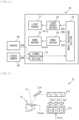
- FIG. 1 illustrates a perspective configuration example of the movable body 1 according to the present embodiment.
- the movable body 1 includes an apparatus (an information display apparatus) that displays drive assist information for a driver 100 of a vehicle body 10.
- the movable body 1 includes, for example, the vehicle body 10 and the information display apparatus mounted on the vehicle body 10.
- the movable body 1 includes, for example, a projector 20 (a light projecting part), a reflector 30, a stereo camera 40, and a sensor 50, as the information display apparatus, for example.
- the stereo camera 40 is a camera that obtains a stereo picture 40A of the driver 100, and includes two monocular cameras 41, for example.
- the stereo camera 40 outputs the stereo picture 40A obtained by imaging to the projector 20.
- a distance sensor or a structured light may be used instead of the stereo camera 40.
- the sensor 50 is a sensor that detects surrounding circumstances, and includes, for example, a laser radar, a stereo camera, a TOF distance sensor, or the like.
- the sensor 50 outputs a detection signal 50A obtained by detection to the projector 20.
- FIG. 2 illustrates an example of functional blocks of the projector 20.
- the projector 20 performs image display in accordance with the laser scanning method.
- the projector 20 includes, for example, a light source 21, a light source driver 22, a MEMS mirror 23, a MEMS driver 24, a signal processing section 25 (a position detecting section and a circumstance detecting section), and an image processing section 26.
- the signal processing section 25 determines whether or not there is a pedestrian behind a pillar 12, for example, on the basis of the detection signal 50A outputted from the sensor 50. In a case where there is a pedestrian behind the pillar 12, the signal processing section 25 outputs, to the image processing section 26, information about a position, a size, or the like of the pedestrian as a detection result (a first detection result).
- the signal processing section 25 further detects an eye of the driver 100, or a position of a site having a predetermined positional relation with the eye of the driver 100 (hereinbelow, referred to as a "position of the eye, etc. of the driver 100") out of the driver 100, on the basis of the stereo picture 40A outputted from the stereo camera 40.
- the signal processing section 25 outputs, as a detection result (a second detection result), the detected positional information to the image processing section 26.
- the image processing section 26 generates drive assist information including, for example, information about the pedestrian behind the pillar 12 on the basis of the first detection result and the second detection result.
- the image processing section 26 further generates an image signal 22A and a timing signal 22B required for generating a luminous flux L1 including the generated drive assist information, and outputs the image signal 22A and the timing signal 22B to the light source driver 22.
- the image processing section 26 further generates a control signal 22C required for two-dimensionally scanning the luminous flux L1 with an irradiated surface (e.g., a surface of the reflector 30), and outputs the control signal 22C to the MEMS driver 24.
- the light source driver 22 generates a signal voltage Vsig that drives the light source 21 on the basis of the image signal 22A and the timing signal 22B each inputted from the image processing section 26, and outputs the signal voltage Vsig to the light source 21.
- the light source 21 is driven by the signal voltage Vsig inputted from the light source driver 22 to project the luminous flux L1 toward the reflector 30 (actually, the MEMS mirror 23). That is, the light source 21 generates and projects the luminous flux L1 on the basis of the first detection result and the second detection result.
- the MEMS driver 24 generates a scanning signal Vscan that drives the MEMS mirror 23, on the basis of the control signal 22C inputted from the image processing section 26, and outputs the scanning signal Vscan to the MEMS mirror 23.
- the MEMS mirror 23 outputs the luminous flux L1 toward the reflector 30, and also two-dimensionally scans the surface of the reflector 30 with the luminous flux L1.
- the MEMS mirror 23 is driven by the scanning signal Vscan inputted from the MEMS driver 24 to perform scanning of the luminous flux L1.
- FIG. 3 illustrates a schematic configuration example of the light source 21.
- the light source 21 includes, for example, a semiconductor laser device 211 operable to emit multiple types of color beams.
- the semiconductor laser device 211 is driven by the signal voltage Vsig inputted from the light source driver 22 to emit each color beam.
- the semiconductor laser device 211 includes, for example, a semiconductor laser (a red semiconductor laser) operable to emit red light, a semiconductor laser (a green semiconductor laser) operable to emit green light, and a semiconductor laser (a blue semiconductor laser) operable to emit blue light.
- the semiconductor laser device 211 may be configured to emit one type of color beam, for example.
- the semiconductor laser device 211 may include, for example, one laser of the red semiconductor laser, the green semiconductor laser, and the blue semiconductor laser.
- the semiconductor laser device 211 may be configured to emit two types of color beams, for example.
- the semiconductor laser device 211 may include, for example, two lasers of the red semiconductor laser, the green semiconductor laser, and the blue semiconductor laser.
- the semiconductor laser device 211 may be configured to emit four or more types of color beams, for example.
- the light source 21 may include a second harmonic generator (SHG) light source.
- the light source 21 further includes, for example, a plurality of collimation lenses 212, a dichroic prism 213, and a mirror 214.
- the plurality of collimation lenses 212 are assigned to respective color beams of the semiconductor laser device 211 on a one-to-one basis to substantially parallelize (collimate) the respective color beams.
- the dichroic prism 213 combines respective color beams substantially parallelized by the plurality of collimation lenses 212 to convert to a single luminous flux L1.
- the mirror 214 reflects the luminous flux L1 generated by the dichroic prism 213 toward the MEMS mirror 23.
- the semiconductor laser device 211 may emit monochromatic light.
- the dichroic prism 213 and the mirror 214 may be omitted.
- the projector 20 may employ a method of image display different from the laser scanning method.
- the projector 20 may employ image display based on a digital light processing (DLP) method, a liquid crystal on silicon (LCOS) method, or a liquid crystal display (LCD), for example.
- DLP digital light processing
- LCOS liquid crystal on silicon
- LCD liquid crystal display
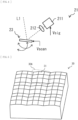
- FIG. 5 illustrates a perspective configuration example of the reflector 30.
- the reflector 30 has a plurality of unit regions 30A two-dimensionally arranged over its main surface.
- Each unit region 30A is a region equivalent to a single pixel in a picture emitted by the projector 20, and has a size equivalent to a spot size of the luminous flux L1 emitted by the projector 20, for example.
- Each unit region 30A has a plurality of reflecting surfaces 31 that are two-dimensionally arranged, and splits the luminous flux L1 entering the plurality of reflecting surfaces 31 to perform reflection in a plurality of directions.
- Each unit region 30A has, for example, as illustrated in FIG. 5 , nine reflecting surfaces 31 divided into three different angles each in a vertical direction and a lateral direction.
- the luminous flux L1 is split into nine different partial luminous fluxes L2 having mutually different angular components.
- FIGs. 6 , 7 , and 8 illustrate examples of workings of the reflector 30.
- FIG. 6 illustrates an example of three partial luminous fluxes L2(1), L2(2), and L2(3) split in a horizontal direction when the luminous flux L1 enters one unit region 30A in the reflector 30 in FIG. 5 .
- FIG. 6 illustrates an example of three partial luminous fluxes L2(1), L2(2), and L2(3) split in a horizontal direction when the luminous flux L1 enters one unit region 30A in the reflector 30 in FIG. 5 .
- FIG. 7 illustrates a positional relation between the three partial luminous fluxes L2(1), L2(2), and L2(3) split in the horizontal direction and the driver 100.
- FIG. 8 illustrates an example of a relation between the three partial luminous fluxes L2(1), L2(2), and L2(3) split in the horizontal direction and eyes of the driver 100.
- the plurality of reflecting surfaces 31 in the respective unit regions 30A are preferably configured to allow pitches D1 between the plurality of partial luminous fluxes L2(1), L2(2), and L2(3) to be equal to or larger than an interval between the eyes of a person (the driver 100) at a predetermined distance from the main surface of the reflector 30.
- predetermined distance refers to a distance from the main surface of the reflector 30 to a location where the eyes of the driver 100 are located. In this manner, it is difficult for the partial luminous flux L2(1) to enter one eye of the driver 100 at the same time as the partial luminous flux L2(2) enters the other eye of the driver 100, for example.
- the plurality of reflecting surfaces 31 of each unit region 30A are preferably configured to allow a spot size D2 of each of the partial luminous fluxes L2(1), L2(2), and L2(3) to be equal to or smaller than the interval between the eyes of the person (the driver 100) at the predetermined distance from the main surface of the reflector 30. This prevents the partial luminous flux L2(1) from entering one eye of the driver 100 at the same time as the partial luminous flux L2(2) enters the other eye of the driver 100, for example.
- FIG. 9 illustrates an example of a relation between a propagation distance of the partial luminous flux L2 in the reflector 30 in FIG. 5 (a distance from the main surface of the reflector 30) and the spot size D2.
- FIG. 8 indicates a result at a time when a wavelength of the luminous flux L1 is the wavelength of green (530 nm) and each reflecting surface 31 has a flat plane. It is appreciated from FIG.
- the spot size D2 is about 1 mm. In this manner, when the spot size D2 is smaller than the size of the eye of the driver 100, the partial luminous flux L2 is more likely to deviate from the eye of the driver 100.
- the plurality of reflecting surfaces 31 of each unit region 30A are preferably configured to allow the spot size D2 of each of the partial luminous fluxes L2(1), L2(2), and L2(3) to be equal to or larger than the size of the eye of the person (the driver 100) at the predetermined distance from the main surface of the reflector 30 and also equal to or smaller than the interval between the eyes of the person (the driver 100).
- each reflecting surface 31 is preferably configured to allow a divergence angle ⁇ 2 of each of the partial luminous fluxes L2(1), L2(2), and L2(3) to be larger than a divergence angle ⁇ 1 of the luminous flux L1.
- Each reflecting surface 31 is preferably, for example, a scattering surface or a convex curved surface.
- the plurality of reflecting surfaces 31 of each unit region 30A are preferably configured to allow as many viewpoints 300 to be formed at the predetermined distance from the main surface of the reflector 30 as the reflecting surfaces 31 included in each unit region 30A by a plurality of partial luminous fluxes L2 outputted from each unit region 30A. This makes it possible to obtain monocular images for multiple viewpoints, for example, because of one eye of the driver 100 being located at the viewpoints 300.
- each reflecting surface 31 In a case where scattering occurs to the surface of each reflecting surface 31, an image is recognized by the driver 100 as a real image on the surface of the reflector 30. The image is projected only to one eye of the driver 100, and thus the image is recognized to be located at the same position as the background. Moreover, it is preferable that each reflecting surface 31 is designed so as not to be seen from a passenger in a passenger seat or the like other than the driver 100. This allows only the driver 100 to obtain necessary information and does not obstruct the passenger's view.
- the reflector 30 is formed, for example, by plastic molded using a mold.
- the reflector 30 may be formed using a 3D printer, for example.
- the surface of the reflector 30 may be coated with a dielectric multilayer film or a metallic film used for controlling reflectance in accordance with its intended use.
- the ratio for dividing each unit region 30A may not be equal in the vertical direction and the lateral direction.
- Each reflecting surface 31 may be two-dimensionally arranged without any gap over the main surface of the reflector 30, for example, as illustrated in FIG. 5 .
- the entire main surface may not necessarily be the reflecting surface 31, but a portion thereof may be a diffusing surface.
- each unit region 30A may further include a diffusing surface 32 surrounding each reflecting surface 31. Isotropic scattering occurs to the diffusing surface 32. An amount of light entering the eye due to the isotropic scattering on the diffusing surface 32 is negligibly small compared to the amount of light entering the eye due to reflection by the reflecting surface 31. Thus, the diffusing surface 32 does not affect the image. Suppression of an unnecessary reflection component caused by external light, texture of the surface, and freedom of design are enhanced.
- a pedestrian behind the pillar 12 is detected on the basis of the detection signal 50A outputted from the sensor 50. Furthermore, the position of the eyes of the driver 100 or the like are detected on the basis of the stereo picture 40A outputted from the stereo camera 40.
- the drive assist information including information, etc. about the pedestrian behind the pillar 12 is generated on the basis of, for example, information about the detected pedestrian and information about the position of the eye of the driver 100, or the like.
- the image signal 22A and the timing signal 22B required for generating the luminous flux L1 including the generated drive assist information are generated, and the signal voltage Vsig and the scanning signal Vscan that drive the light source 21 are generated on the basis of the image signal 22A and the timing signal 22B that are generated.
- the light source 21 driven by the signal voltage Vsig and the scanning signal Vscan emits the luminous flux L1, and the emitted luminous flux L1 is scanned and reflected by the main surface of the reflector 30.
- the luminous flux L1 is split into as many partial luminous fluxes L2 as the reflecting surfaces 31 included in each unit region 30A.
- the plurality of partial luminous fluxes L2 outputted from each unit region 30A form as many viewpoints 300 at the predetermined distance from the main surface of the reflector 30 as the reflecting surfaces 31 included in each unit region 30A.
- Each viewpoint 300 is generated near the eyes of the driver 100, thus, for example, an image as illustrated in FIG. 11 (image including a pedestrian 200) is visually recognized on the surface of the pillar 12, with the viewpoint 300 coming into one eye of the driver 100.
- the viewpoint 300 is located in only one eye of the driver 100, and thus the image on the surface of the pillar 12 is recognized to be at the same position as the background of the pillar 12. In this manner, the drive assist is performed for the driver 100.
- an optical camouflage and a head-up display (Head-Up Display: HUD) as an apparatus (an information display apparatus) that displays drive assist information such as a warning to a vehicle driver.
- the optical camouflage forms a retroreflecting surface in a pillar region, for example, and projects a background image from a direction closer to a line of sight of the driver using a projector (see, for example, Japanese Unexamined Patent Application Publication No. 2005-199934 ).
- the real image is displayed on a pillar part.
- the distant point is focused, and thus the image of the pillar is recognized as double images, which is indistinct.
- a depth position of the image displayed by the HUD is an optical virtual image position, which is set at a position 2 to 3 meters ahead of the driver in many cases.
- the display image of the HUD is recognized as double images, which is indistinct.
- the position 2 to 3 meters ahead is focused on, which makes it difficult to recognize a distant scenery at the same time.
- the mismatch between accommodation and convergence is so large as to easily cause fatigue.
- a monocular HUD used to observe the display image with one eye (see, for example, Japanese Unexamined Patent Application Publication No. H7-228172 ).
- the monocular HUD has such issues that the position of the head allowing for monocular viewing is limited and that it is difficult to increase the screen size, because of its simple structure using a light shielding plate.
- the image is focused on with the background scenery being blurred, which becomes an issue.
- a projector that employs the laser scanning method is used.
- the laser scanning method generates small tinge of white because of no light emission of the light source with the black signal.
- the optical camouflage on the pillar part and the HUD involve such an issue as the fatigue from the mismatch between accommodation and convergence and double images of display information due to binocular parallax when viewing a distant scenery during driving.
- a monocular system has an issue in either the designability or in the increased screen size because the multiple viewpoints corresponding to a plurality of head positions and a combiner are required. From those described above, there is not a suitable monocular HUD corresponding to the multiple viewpoints to achieve high designability and increased screen size.
- each of the unit regions 30A two-dimensionally arranged over the main surface of the reflector 30 is provided with the plurality of reflecting surfaces 31, and the luminous flux L1 entering the plurality of reflecting surfaces 31 is split and reflected in a plurality of directions.
- the movable body 1 in a case where the plurality of reflecting surfaces 31 of each unit region 30A are configured to allow as many viewpoints 300 to be formed at the predetermined distance from the main surface of the reflector 30 as the reflecting surfaces 31 included in each unit region 30A by the plurality of partial luminous fluxes L2 outputted from each unit region 30A, for example, it is possible to position the viewpoint 300 in only one eye of the driver 100. Thus, it becomes possible to make the driver 100 recognize as if the image from the reflector 30 is displayed in a position of the background. As a result, it is possible to prevent a blurred scenery when the driver 100 focuses on the image on the reflector 30 and to prevent a blurred image on the reflector 30 when focusing on the scenery.
- the plurality of reflecting surfaces 31 of each unit region 30A are configured to allow the pitches D1 between the plurality of partial luminous fluxes L2(1), L2(2), and L2(3) to be equal to or larger than the interval between the eyes of the person (the driver 100) at the predetermined distance from the main surface of the reflector 30, for example, the partial luminous flux L2(2) hardly enters one eye of the driver 100 at the same time as the partial luminous flux L2(1) enters the other eye of the driver 100.
- the movable body 1 in a case where the plurality of reflecting surfaces 31 of each unit region 30A are configured to allow the spot size D2 of each of the partial luminous fluxes L2(1), L2(2), and L2(3) to be equal to or smaller than the interval between the eyes of the person (the driver 100) at the predetermined distance from the main surface of the reflector 30, for example, the partial luminous flux L2(1) is prevented from entering one eye of the driver 100 at the same time as the partial luminous flux L2(2) enters the other eye of the driver 100.
- This makes it possible to make the driver 100 recognize as if the image on the reflector 30 is displayed at the position of the scenery.
- the plurality of reflecting surfaces 31 of each unit region 30A are configured to allow the spot size D2 of each of the partial luminous fluxes L2(1), L2(2), and L2(3) to be equal to or larger than the size of the eye of the person (the driver 100) at the predetermined distance from the main surface of the reflector 30 and also equal to or smaller than the interval between the eyes of the person (the driver 100), for example, not only the partial luminous flux L2(2) is prevented from entering one eye of the driver 100 at the same time as the partial luminous flux L2(1) enters the other eye of the driver 100, but also the partial luminous flux L2 hardly deviates from the eye of the driver 100.
- each reflecting surface 31 is configured to allow the divergence angle ⁇ 2 of each of the partial luminous fluxes L2(1), L2(2), and L2(3) to be larger than the divergence angle ⁇ 1 of the luminous flux L1
- the partial luminous flux L2 hardly deviates from the eye of the driver 100. As a result, it is possible to view the picture constantly on the surface of the reflector 30.
- the movable body 1 in a case where the reflecting surfaces 31 are two-dimensionally arranged without any gap over the main surface of the diffuser 30, for example, it is possible to manufacture the diffuser 30 using a simple mold. As a result, it is possible to provide the diffuser 30 at a low cost.
- each unit region 30A further includes the diffusing surface 32 surrounding each reflecting surface 31, isotropic scattering occurs on the diffusing surface 32.
- An amount of light entering the eye due to the isotropic scattering on the diffusing surface 32 is negligibly small compared to the amount of light entering the eye due to the reflection by the reflecting surface 31.
- the diffusing surface 32 does not affect the image. As a result, it is possible to suppress an unnecessary reflection component caused by the external light and to improve the texture of the surface and the freedom of design.
- the semiconductor laser device 211 in a case where the image is displayed on the reflector 30 by directly modulating the luminous flux L1 in accordance with scanning of the MEMS mirror 23, the semiconductor laser device 211 does not emit light with a black signal. Therefore, there is less possibility of degrading the background scenery due to white tinge. It is further possible to suppress power consumption of the projector 20. Moreover, in the present embodiment, in a case where collimated light is scanned, the projector 20 is focus-free, thus making it possible to cope with various shapes and arrangements of the reflector 30.
- the reflector 30 may be disposed on the dashboard 13 or may constitute a portion of the dashboard 13.
- the luminous flux L1 projected from the projector 20 is reflected in a direction of a windshield 11 by the reflector 30 that is on the dashboard 13 or constitute a portion of the dashboard 13.
- a component reflected again by the windshield 11 reaches one eye of the driver 100.
- Each reflecting surface 31 has an angle that reflects a three-dimensional shape of the windshield 11 and that takes into consideration the position of an eye of the driver 100, as illustrated in FIG. 13 , for example.
- the angle of the reflecting surface 31 is small near the front of the driver 100, and the angle of the reflecting surface 31 becomes larger the farther away from the front of the driver 100.
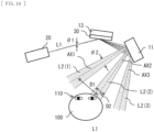
- FIG. 14 illustrates a positional relation between the three partial luminous fluxes L2(1), L2(2), and L2(3) split in the horizontal direction and the driver 100.
- FIG. 15 illustrates an example of a relation between the three partial luminous fluxes L2(1), L2(2), and L2(3) split in the horizontal direction and the eye of the driver 100.
- the plurality of reflecting surfaces 31 of each unit region 30A are preferably configured to allow the pitches D1 between the plurality of partial luminous fluxes L2(1), L2(2), and L2(3) to be equal to or larger than the interval between the eyes of the person (the driver 100) at the predetermined distance from the main surface of the reflector 30 via the surface of the windshield 11.
- predetermined distance refers to a distance from the main surface of the reflector 30 to the location where the eye of the driver 100 is present via the surface of the windshield 11. In this manner, for example, it is difficult for the partial luminous flux L2(1) to enter one eye of the driver 100 at the same time as the partial luminous flux L2(2) enters the other eye of the driver 100, for example.
- the plurality of reflecting surfaces 31 of each unit region 30A are preferably configured to allow a spot size D2 of each of the partial luminous fluxes L2(1), L2(2), and L2(3) to be equal to or smaller than the interval between the eyes of the person (the driver 100) at the predetermined distance from the main surface of the reflector 30 via the windshield 11. This prevents the partial luminous flux L2(1) from entering one eye of the driver 100 at the same time as the partial luminous flux L2(2) enters the other eye of the driver 100, for example.
- an increased proportion of an image region of the HUD to the scenery during driving obstructs the view of the driver. It is therefore preferable that an area occupied by the display region in the windshield 11 should be in a range not exceeding 20%.
- the reflector 30 may be provided across the entire dashboard 13 as illustrated in FIG. 16 , for example, or may be provided at a portion of the dashboard 13 (e.g., a right end of the dashboard 13) as illustrated in FIG. 17 , for example. Even in a case where the reflector 30 is provided across the entire dashboard 13, only a less component of scattering light from the reflector 30 enters the eyes of the driver 100, because the reflection direction is controlled by the reflector 30.
- the view of the driver 100 is less obstructed compared to a case where a direct-view-type display is installed on the dashboard 13. Moreover, it is preferable that image should be invisible from the other people than the driver 100 through design not to obstruct the view of other people than the driver 100.
- the reflector 30 may be provided, for example, at a location that is likely to be a blind spot for the driver 100 such as a back side of a door, a ceiling, and a seat of the vehicle body 10.
Landscapes
- Engineering & Computer Science (AREA)
- Physics & Mathematics (AREA)
- General Physics & Mathematics (AREA)
- Mechanical Engineering (AREA)
- Optics & Photonics (AREA)
- Combustion & Propulsion (AREA)
- Chemical & Material Sciences (AREA)
- Transportation (AREA)
- Theoretical Computer Science (AREA)
- General Engineering & Computer Science (AREA)
- Human Computer Interaction (AREA)
- Instrument Panels (AREA)
- Variable-Direction Aerials And Aerial Arrays (AREA)
- Multimedia (AREA)
Description
- The present disclosure relates to a reflector, an information display apparatus, and a movable body.
- There are an optical camouflage and a head-up display (Head-Up Display: HUD) as an apparatus that displays drive assist information such as a warning to a vehicle driver (see
PTLs 1 to 7 below). The optical camouflage is a view aiding apparatus that improves driving safety by projecting an image of a background onto a region, such as a pillar, that is a blind spot for the driver. The HUD is a display apparatus that makes it possible to view an image and a background overlaid one on top of the other at a time by reflecting the image from a projector or the like on a combiner such as a half mirror provided at a windshield or the like. -
US 8503087 B1 discloses a reflector which is an optical structure comprising an array of mirrors arranged on a substrate. The mirrors are arranged above a surface of the substrate and are oriented at a plurality of different oblique angles relative to the surface of the substrate. The substrate comprises a clear substrate to guide external light through spaces between the mirror structures so that the optical structure is partially transparent and partially reflective. The optical structure can optionally be illuminated with an image source that emits essentially a single beam of light per pixel of the image source to provide an optical system. - European Patent
Application Publication EP 1 939 040 A2 provides a driving support method and a driving support apparatus, both capable of projecting an image of a specific target object on a pillar, wherein the driving support apparatus includes a camera installed in a vehicle that films a dead-angle area caused by a pillar of a vehicle and projects an image filmed by the camera on the inner surface of the pillar. - From
US 2013/120825 A1 a heads-up display system is known, which is configured for use in a vehicle. The system includes a standard vehicle window (i.e. no special coatings), an image projector, and a vehicle dashboard equipped with a faceted reflective surface. The image projector is configured to project an image onto the faceted reflective surface. The faceted reflective surface is configured to reflect the image from the image projector onto a window surface of the standard vehicle window. The window surface is oriented to reflect the image from the faceted reflective surface toward an occupant. -
US 2005/168695 A1 discloses a vehicular visual assistance system that includes: a retro-reflective surface formed on an inside face of a pillar that is in a position which obstructs the view of a vehicle driver seated on a driver's seat within a vehicle compartment; a camera mounted on the vehicle outside the vehicle compartment for taking an image outward from the pillar in a direction that is substantially the same as the line of vision of the vehicle driver on the driver's seat; and a projector for projecting in real time the image taken by the camera toward the retro-reflective surface of the pillar. The projector is fixedly disposed within the vehicle compartment at a position close to the eyes of the vehicle driver on the driver's seat. Thus, it is possible to eliminate a blind spot due to the pillar. -
JP 2001 108939 A -
- PTL 1:
Japanese Unexamined Patent Application Publication No. 2005-199934 - PTL 2:
Japanese Unexamined Patent Application Publication No. 2013-171252 - PTL 3:
Japanese Unexamined Patent Application Publication No. H7-228172 - PTL 4:
Japanese Unexamined Patent Application Publication No. 2010-156929 - PTL 5:
Japanese Unexamined Patent Application Publication No. 2010-70117 - PTL 6:
Japanese Unexamined Patent Application Publication No. 2012-39397 - PTL 7:
Japanese Unexamined Patent Application Publication No. H7-156685 - In an attempt to achieve monocular vision and multiple viewpoints using a reflector in an information display apparatus as described above, an installation location of a light projection unit such as a projector (hereinbelow, referred to as a "light projection unit") is significantly restricted. It is therefore desirable to provide a reflector, an information display apparatus, and a movable body that make it possible to relax the restriction on the installation location of the light projection unit.
According to a first aspect, the present invention provides an information display apparatus in accordance withindependent claim 1. According to a second aspect, the present invention provides a movable body in accordance withindependent claim 7. Further aspects of the present invention are set forth in the dependent claims, the drawings and the following description. - A reflector according to an embodiment of the present disclosure includes a plurality of unit regions two-dimensionally arranged over a main surface. Each of the unit regions includes a plurality of reflecting surfaces two-dimensionally arranged, and splits a luminous flux entering the plurality of reflecting surfaces to perform reflection in a plurality of directions.
- An information display apparatus according to an embodiment of the present disclosure includes a light projecting part that projects a luminous flux and a reflector that reflects the luminous flux from the light projecting part. The reflector has a plurality of unit regions two-dimensionally arranged over a main surface. Each of the unit regions includes a plurality of reflecting surfaces two-dimensionally arranged, and splits a luminous flux entering the plurality of reflecting surfaces to perform reflection in a plurality of directions.
- A movable body according to an embodiment of the present disclosure includes a vehicle body and an information display apparatus mounted on the vehicle body. The information display apparatus provided at the movable body is the same component as the above-described information display apparatus.
- In the reflector, the information display apparatus, and the movable body according to respective embodiments of the present disclosure, each of the unit regions two-dimensionally arranged over the main surface of the reflector is provided with a plurality of reflecting surfaces two-dimensionally arranged, and a luminous flux entering the plurality of reflecting surfaces is split and reflected in a plurality of directions. This makes it possible to achieve monocular vision and multiple viewpoints using the reflector by appropriately designing an angle of each of the reflecting surfaces in accordance with the installation location of the light projection unit. That is, there is no need of installing the light projection unit on the same axis as the reflector, thus allowing for more freedom for the installation location of the light projection unit.
- In accordance with the reflector, the information display apparatus, and the movable body according to respective embodiments of the present disclosure, each of the unit regions two-dimensionally arranged over the main surface of the reflector is provided with the plurality of reflecting surfaces two-dimensionally arranged and the luminous flux entering the plurality of reflecting surfaces is split and reflected in a plurality of directions, thus making it possible to relax the restriction on the installation location of the light projection unit. It is to be noted that the effects of the present disclosure are not necessarily limited to the effects described here, and may be any of the effects described in the present specification.
-
- [
FIG. 1] FIG. 1 illustrates a perspective configuration example of a movable body according to an embodiment of the present disclosure. - [
FIG. 2] FIG. 2 illustrates an example of functional blocks of a projector inFIG. 1 . - [
FIG. 3] FIG. 3 illustrates a schematic configuration example of a light source inFIG. 2 . - [
FIG. 4] FIG. 4 illustrates the schematic configuration example of the light source inFIG. 2 . - [
FIG. 5] FIG. 5 illustrates a perspective configuration example of a reflector inFIG. 1 . - [
FIG. 6] FIG. 6 illustrates an example of workings of the reflector inFIG. 5 . - [
FIG. 7] FIG. 7 illustrates an example of workings of the reflector inFIG. 5 . - [
FIG. 8] FIG. 8 illustrates an example of workings of the reflector inFIG. 5 . - [
FIG. 9] FIG. 9 illustrates an example of a relation between a propagation distance of a partial luminous flux and a spot size in the reflector inFIG. 5 . - [
FIG. 10] FIG. 10 illustrates a perspective configuration example of the reflector inFIG. 1 . - [
FIG. 11] FIG. 11 illustrates an example of a displayed picture. - [
FIG. 12] FIG. 12 illustrates a modification example of a perspective configuration of the movable body inFIG. 1 . - [
FIG. 13] FIG. 13 illustrates an example of a configuration of a reflector inFIG. 12 . - [
FIG. 14] FIG. 14 illustrates an example of workings of the reflector inFIG. 12 . - [
FIG. 15] FIG. 15 illustrates an example of the workings of the reflector inFIG. 12 . - [
FIG. 16] FIG. 16 illustrates a modification example of the perspective configuration of the movable body inFIG. 1 . - [
FIG. 17] FIG. 17 illustrates a modification example of the perspective configuration of the movable body inFIG. 1 . - In the following, embodiments for carrying out the present disclosure are described in detail with reference to drawings. The following description is directed to specific examples of the present disclosure, and the present disclosure is not limited to the following embodiments. Moreover, the present disclosure is not limited to positions, dimensions, dimension ratios, and other factors of respective components illustrated in the drawings. It is to be noted that the description is given in the following order.
- An example in which a pillar is provided with a reflector
- An example in which a dashboard is provided with a reflector
- Described below is a configuration of a
movable body 1 according to a first embodiment of the present disclosure.FIG. 1 illustrates a perspective configuration example of themovable body 1 according to the present embodiment. Themovable body 1 includes an apparatus (an information display apparatus) that displays drive assist information for adriver 100 of avehicle body 10. Themovable body 1 includes, for example, thevehicle body 10 and the information display apparatus mounted on thevehicle body 10. Themovable body 1 includes, for example, a projector 20 (a light projecting part), areflector 30, astereo camera 40, and asensor 50, as the information display apparatus, for example. - The
stereo camera 40 is a camera that obtains astereo picture 40A of thedriver 100, and includes twomonocular cameras 41, for example. Thestereo camera 40 outputs thestereo picture 40A obtained by imaging to theprojector 20. It is to be noted that, for example, a distance sensor or a structured light may be used instead of thestereo camera 40. Thesensor 50 is a sensor that detects surrounding circumstances, and includes, for example, a laser radar, a stereo camera, a TOF distance sensor, or the like. Thesensor 50 outputs adetection signal 50A obtained by detection to theprojector 20. -
FIG. 2 illustrates an example of functional blocks of theprojector 20. Theprojector 20 performs image display in accordance with the laser scanning method. Theprojector 20 includes, for example, alight source 21, alight source driver 22, aMEMS mirror 23, aMEMS driver 24, a signal processing section 25 (a position detecting section and a circumstance detecting section), and animage processing section 26. - The
signal processing section 25 determines whether or not there is a pedestrian behind apillar 12, for example, on the basis of thedetection signal 50A outputted from thesensor 50. In a case where there is a pedestrian behind thepillar 12, thesignal processing section 25 outputs, to theimage processing section 26, information about a position, a size, or the like of the pedestrian as a detection result (a first detection result). Thesignal processing section 25 further detects an eye of thedriver 100, or a position of a site having a predetermined positional relation with the eye of the driver 100 (hereinbelow, referred to as a "position of the eye, etc. of thedriver 100") out of thedriver 100, on the basis of thestereo picture 40A outputted from thestereo camera 40. Thesignal processing section 25 outputs, as a detection result (a second detection result), the detected positional information to theimage processing section 26. - The
image processing section 26 generates drive assist information including, for example, information about the pedestrian behind thepillar 12 on the basis of the first detection result and the second detection result. Theimage processing section 26 further generates animage signal 22A and atiming signal 22B required for generating a luminous flux L1 including the generated drive assist information, and outputs theimage signal 22A and thetiming signal 22B to thelight source driver 22. Theimage processing section 26 further generates acontrol signal 22C required for two-dimensionally scanning the luminous flux L1 with an irradiated surface (e.g., a surface of the reflector 30), and outputs thecontrol signal 22C to theMEMS driver 24. - The
light source driver 22 generates a signal voltage Vsig that drives thelight source 21 on the basis of theimage signal 22A and thetiming signal 22B each inputted from theimage processing section 26, and outputs the signal voltage Vsig to thelight source 21. Thelight source 21 is driven by the signal voltage Vsig inputted from thelight source driver 22 to project the luminous flux L1 toward the reflector 30 (actually, the MEMS mirror 23). That is, thelight source 21 generates and projects the luminous flux L1 on the basis of the first detection result and the second detection result. TheMEMS driver 24 generates a scanning signal Vscan that drives theMEMS mirror 23, on the basis of thecontrol signal 22C inputted from theimage processing section 26, and outputs the scanning signal Vscan to theMEMS mirror 23. TheMEMS mirror 23 outputs the luminous flux L1 toward thereflector 30, and also two-dimensionally scans the surface of thereflector 30 with the luminous flux L1. TheMEMS mirror 23 is driven by the scanning signal Vscan inputted from theMEMS driver 24 to perform scanning of the luminous flux L1. -
FIG. 3 illustrates a schematic configuration example of thelight source 21. Thelight source 21 includes, for example, asemiconductor laser device 211 operable to emit multiple types of color beams. Thesemiconductor laser device 211 is driven by the signal voltage Vsig inputted from thelight source driver 22 to emit each color beam. Thesemiconductor laser device 211 includes, for example, a semiconductor laser (a red semiconductor laser) operable to emit red light, a semiconductor laser (a green semiconductor laser) operable to emit green light, and a semiconductor laser (a blue semiconductor laser) operable to emit blue light. Moreover, thesemiconductor laser device 211 may be configured to emit one type of color beam, for example. Thesemiconductor laser device 211 may include, for example, one laser of the red semiconductor laser, the green semiconductor laser, and the blue semiconductor laser. Moreover, thesemiconductor laser device 211 may be configured to emit two types of color beams, for example. Thesemiconductor laser device 211 may include, for example, two lasers of the red semiconductor laser, the green semiconductor laser, and the blue semiconductor laser. Moreover, thesemiconductor laser device 211 may be configured to emit four or more types of color beams, for example. Moreover, thelight source 21 may include a second harmonic generator (SHG) light source. - The
light source 21 further includes, for example, a plurality ofcollimation lenses 212, adichroic prism 213, and amirror 214. The plurality ofcollimation lenses 212 are assigned to respective color beams of thesemiconductor laser device 211 on a one-to-one basis to substantially parallelize (collimate) the respective color beams. Thedichroic prism 213 combines respective color beams substantially parallelized by the plurality ofcollimation lenses 212 to convert to a single luminous flux L1. Themirror 214 reflects the luminous flux L1 generated by thedichroic prism 213 toward theMEMS mirror 23. - It is to be noted that, as illustrated in
FIG. 4 , for example, thesemiconductor laser device 211 may emit monochromatic light. In that case, however, thedichroic prism 213 and themirror 214 may be omitted. Theprojector 20 may employ a method of image display different from the laser scanning method. Theprojector 20 may employ image display based on a digital light processing (DLP) method, a liquid crystal on silicon (LCOS) method, or a liquid crystal display (LCD), for example. - Next, description is given of the
reflector 30.FIG. 5 illustrates a perspective configuration example of thereflector 30. Thereflector 30 has a plurality ofunit regions 30A two-dimensionally arranged over its main surface. Eachunit region 30A is a region equivalent to a single pixel in a picture emitted by theprojector 20, and has a size equivalent to a spot size of the luminous flux L1 emitted by theprojector 20, for example. Eachunit region 30A has a plurality of reflectingsurfaces 31 that are two-dimensionally arranged, and splits the luminous flux L1 entering the plurality of reflectingsurfaces 31 to perform reflection in a plurality of directions. - Each
unit region 30A has, for example, as illustrated inFIG. 5 , nine reflectingsurfaces 31 divided into three different angles each in a vertical direction and a lateral direction. In this case, the luminous flux L1 is split into nine different partial luminous fluxes L2 having mutually different angular components.FIGs. 6 ,7 , and8 illustrate examples of workings of thereflector 30.FIG. 6 illustrates an example of three partial luminous fluxes L2(1), L2(2), and L2(3) split in a horizontal direction when the luminous flux L1 enters oneunit region 30A in thereflector 30 inFIG. 5 .FIG. 7 illustrates a positional relation between the three partial luminous fluxes L2(1), L2(2), and L2(3) split in the horizontal direction and thedriver 100.FIG. 8 illustrates an example of a relation between the three partial luminous fluxes L2(1), L2(2), and L2(3) split in the horizontal direction and eyes of thedriver 100. - The plurality of reflecting
surfaces 31 in therespective unit regions 30A are preferably configured to allow pitches D1 between the plurality of partial luminous fluxes L2(1), L2(2), and L2(3) to be equal to or larger than an interval between the eyes of a person (the driver 100) at a predetermined distance from the main surface of thereflector 30. It is to be noted that, hereinbelow, "predetermined distance" refers to a distance from the main surface of thereflector 30 to a location where the eyes of thedriver 100 are located. In this manner, it is difficult for the partial luminous flux L2(1) to enter one eye of thedriver 100 at the same time as the partial luminous flux L2(2) enters the other eye of thedriver 100, for example. Furthermore, the plurality of reflectingsurfaces 31 of eachunit region 30A are preferably configured to allow a spot size D2 of each of the partial luminous fluxes L2(1), L2(2), and L2(3) to be equal to or smaller than the interval between the eyes of the person (the driver 100) at the predetermined distance from the main surface of thereflector 30. This prevents the partial luminous flux L2(1) from entering one eye of thedriver 100 at the same time as the partial luminous flux L2(2) enters the other eye of thedriver 100, for example. - Here, in a case where the size of each
unit region 30A is set to 1 mm and eachunit region 30A is divided into three each in the vertical and lateral directions, the size of one reflectingsurface 31 with one angular component is 0.33 mm × 0.33 mm.FIG. 9 illustrates an example of a relation between a propagation distance of the partial luminous flux L2 in thereflector 30 inFIG. 5 (a distance from the main surface of the reflector 30) and the spot size D2.FIG. 8 indicates a result at a time when a wavelength of the luminous flux L1 is the wavelength of green (530 nm) and each reflectingsurface 31 has a flat plane. It is appreciated fromFIG. 8 that, assuming the eye of thedriver 100 is located at 500 mm from the main surface of thereflector 30, beam divergence by diffraction (the spot size D2) is about 1 mm. In this manner, when the spot size D2 is smaller than the size of the eye of thedriver 100, the partial luminous flux L2 is more likely to deviate from the eye of thedriver 100. Thus, the plurality of reflectingsurfaces 31 of eachunit region 30A are preferably configured to allow the spot size D2 of each of the partial luminous fluxes L2(1), L2(2), and L2(3) to be equal to or larger than the size of the eye of the person (the driver 100) at the predetermined distance from the main surface of thereflector 30 and also equal to or smaller than the interval between the eyes of the person (the driver 100). At this time, each reflectingsurface 31 is preferably configured to allow a divergence angle θ2 of each of the partial luminous fluxes L2(1), L2(2), and L2(3) to be larger than a divergence angle θ1 of the luminous flux L1. Each reflectingsurface 31 is preferably, for example, a scattering surface or a convex curved surface. - The plurality of reflecting
surfaces 31 of eachunit region 30A are preferably configured to allow asmany viewpoints 300 to be formed at the predetermined distance from the main surface of thereflector 30 as the reflectingsurfaces 31 included in eachunit region 30A by a plurality of partial luminous fluxes L2 outputted from eachunit region 30A. This makes it possible to obtain monocular images for multiple viewpoints, for example, because of one eye of thedriver 100 being located at theviewpoints 300. - In a case where scattering occurs to the surface of each reflecting
surface 31, an image is recognized by thedriver 100 as a real image on the surface of thereflector 30. The image is projected only to one eye of thedriver 100, and thus the image is recognized to be located at the same position as the background. Moreover, it is preferable that each reflectingsurface 31 is designed so as not to be seen from a passenger in a passenger seat or the like other than thedriver 100. This allows only thedriver 100 to obtain necessary information and does not obstruct the passenger's view. - The
reflector 30 is formed, for example, by plastic molded using a mold. Thereflector 30 may be formed using a 3D printer, for example. The surface of thereflector 30 may be coated with a dielectric multilayer film or a metallic film used for controlling reflectance in accordance with its intended use. The ratio for dividing eachunit region 30A may not be equal in the vertical direction and the lateral direction. - Each reflecting
surface 31 may be two-dimensionally arranged without any gap over the main surface of thereflector 30, for example, as illustrated inFIG. 5 . However, in thereflector 30, the entire main surface may not necessarily be the reflectingsurface 31, but a portion thereof may be a diffusing surface. For example, as illustrated inFIG. 10 , eachunit region 30A may further include a diffusingsurface 32 surrounding each reflectingsurface 31. Isotropic scattering occurs to the diffusingsurface 32. An amount of light entering the eye due to the isotropic scattering on the diffusingsurface 32 is negligibly small compared to the amount of light entering the eye due to reflection by the reflectingsurface 31. Thus, the diffusingsurface 32 does not affect the image. Suppression of an unnecessary reflection component caused by external light, texture of the surface, and freedom of design are enhanced. - Next, description is given of an operation of the
movable body 1 according to the present embodiment. In the present embodiment, firstly, for example, a pedestrian behind thepillar 12 is detected on the basis of thedetection signal 50A outputted from thesensor 50. Furthermore, the position of the eyes of thedriver 100 or the like are detected on the basis of thestereo picture 40A outputted from thestereo camera 40. Next, for example, the drive assist information including information, etc. about the pedestrian behind thepillar 12 is generated on the basis of, for example, information about the detected pedestrian and information about the position of the eye of thedriver 100, or the like. Next, for example, theimage signal 22A and thetiming signal 22B required for generating the luminous flux L1 including the generated drive assist information are generated, and the signal voltage Vsig and the scanning signal Vscan that drive thelight source 21 are generated on the basis of theimage signal 22A and thetiming signal 22B that are generated. Next, thelight source 21 driven by the signal voltage Vsig and the scanning signal Vscan emits the luminous flux L1, and the emitted luminous flux L1 is scanned and reflected by the main surface of thereflector 30. Thus, in eachunit region 30A, the luminous flux L1 is split into as many partial luminous fluxes L2 as the reflectingsurfaces 31 included in eachunit region 30A. Furthermore, the plurality of partial luminous fluxes L2 outputted from eachunit region 30A form asmany viewpoints 300 at the predetermined distance from the main surface of thereflector 30 as the reflectingsurfaces 31 included in eachunit region 30A. Eachviewpoint 300 is generated near the eyes of thedriver 100, thus, for example, an image as illustrated inFIG. 11 (image including a pedestrian 200) is visually recognized on the surface of thepillar 12, with theviewpoint 300 coming into one eye of thedriver 100. At this time, theviewpoint 300 is located in only one eye of thedriver 100, and thus the image on the surface of thepillar 12 is recognized to be at the same position as the background of thepillar 12. In this manner, the drive assist is performed for thedriver 100. - Next, description is given of effects of the
movable body 1 according to the present embodiment. - There are an optical camouflage and a head-up display (Head-Up Display: HUD) as an apparatus (an information display apparatus) that displays drive assist information such as a warning to a vehicle driver. The optical camouflage forms a retroreflecting surface in a pillar region, for example, and projects a background image from a direction closer to a line of sight of the driver using a projector (see, for example,
Japanese Unexamined Patent Application Publication No. 2005-199934 Japanese Unexamined Patent Application Publication No. 2013-171252 - In contrast, in the case of the HUD, the image is displayed to both eyes of the driver. A depth position of the image displayed by the HUD is an optical virtual image position, which is set at a
position 2 to 3 meters ahead of the driver in many cases. Accordingly, in the case of the binocular HUD, when the driver tries to view the display of the HUD while viewing a distant point, the display image of the HUD is recognized as double images, which is indistinct. To the contrary, when trying to view the display image of the HUD, theposition 2 to 3 meters ahead is focused on, which makes it difficult to recognize a distant scenery at the same time. In a case where an image to be projected to both eyes is set at a distant point, the mismatch between accommodation and convergence is so large as to easily cause fatigue. - In order to solve such an issue resulting from the binocular parallax, there is proposed a monocular HUD used to observe the display image with one eye (see, for example,
Japanese Unexamined Patent Application Publication No. H7-228172 Japanese Unexamined Patent Application Publication No. 2010-156929 Japanese Unexamined Patent Application Publication No. 2010-70117 Japanese Unexamined Patent Application Publication No. 2012-39397 - In addition, there is also proposed a method of installing, as a binocular HUD, a direct-view-type display apparatus that uses a parallax barrier or a lenticular lens over the dashboard (see, for example,
Japanese Unexamined Patent Application Publication No. H7-156685 - In contrast, in the
movable body 1 according to the present embodiment, each of theunit regions 30A two-dimensionally arranged over the main surface of thereflector 30 is provided with the plurality of reflectingsurfaces 31, and the luminous flux L1 entering the plurality of reflectingsurfaces 31 is split and reflected in a plurality of directions. This makes it possible to achieve the monocular vision and the multiple viewpoints using thereflector 30 by appropriately designing an angle of each reflectingsurface 31 in accordance with the installation location of thelight projector 20. That is, there is no need of installing theprojector 20 on the same axis as thereflector 30, which allows for more freedom for the installation location and the design of theprojector 20 or thereflector 30. Accordingly, it is possible to relax the restriction on the installation location and the design of theprojector 20 or thereflector 30. - Moreover, in the
movable body 1 according to the present embodiment, in a case where the plurality of reflectingsurfaces 31 of eachunit region 30A are configured to allow asmany viewpoints 300 to be formed at the predetermined distance from the main surface of thereflector 30 as the reflectingsurfaces 31 included in eachunit region 30A by the plurality of partial luminous fluxes L2 outputted from eachunit region 30A, for example, it is possible to position theviewpoint 300 in only one eye of thedriver 100. Thus, it becomes possible to make thedriver 100 recognize as if the image from thereflector 30 is displayed in a position of the background. As a result, it is possible to prevent a blurred scenery when thedriver 100 focuses on the image on thereflector 30 and to prevent a blurred image on thereflector 30 when focusing on the scenery. - Moreover, in the
movable body 1 according to the present invention the plurality of reflectingsurfaces 31 of eachunit region 30A are configured to allow the pitches D1 between the plurality of partial luminous fluxes L2(1), L2(2), and L2(3) to be equal to or larger than the interval between the eyes of the person (the driver 100) at the predetermined distance from the main surface of thereflector 30, for example, the partial luminous flux L2(2) hardly enters one eye of thedriver 100 at the same time as the partial luminous flux L2(1) enters the other eye of thedriver 100. This makes it possible to make thedriver 100 recognize as if the image on thereflector 30 is displayed at the position of the scenery. As a result, it is possible to prevent the blurred scenery when thedriver 100 focuses on the image on thereflector 30 and to prevent the blurred image on thereflector 30 when focusing on the scenery. - Furthermore, in the
movable body 1 according to the present embodiment, in a case where the plurality of reflectingsurfaces 31 of eachunit region 30A are configured to allow the spot size D2 of each of the partial luminous fluxes L2(1), L2(2), and L2(3) to be equal to or smaller than the interval between the eyes of the person (the driver 100) at the predetermined distance from the main surface of thereflector 30, for example, the partial luminous flux L2(1) is prevented from entering one eye of thedriver 100 at the same time as the partial luminous flux L2(2) enters the other eye of thedriver 100. This makes it possible to make thedriver 100 recognize as if the image on thereflector 30 is displayed at the position of the scenery. As a result, it is possible to prevent the blurred scenery when thedriver 100 focuses on the image on thereflector 30 and to prevent the blurred image on thereflector 30 when focusing on the scenery. - Moreover, in the
movable body 1 according to the present embodiment, in a case where the plurality of reflectingsurfaces 31 of eachunit region 30A are configured to allow the spot size D2 of each of the partial luminous fluxes L2(1), L2(2), and L2(3) to be equal to or larger than the size of the eye of the person (the driver 100) at the predetermined distance from the main surface of thereflector 30 and also equal to or smaller than the interval between the eyes of the person (the driver 100), for example, not only the partial luminous flux L2(2) is prevented from entering one eye of thedriver 100 at the same time as the partial luminous flux L2(1) enters the other eye of thedriver 100, but also the partial luminous flux L2 hardly deviates from the eye of thedriver 100. This makes it possible to make thedriver 100 recognize as if the image on thereflector 30 is displayed constantly at the position of the background. As a result, it is possible to prevent the blurred scenery when thedriver 100 focuses on the image on thereflector 30 and to prevent the blurred image on thereflector 30 when focusing on the scenery. - Moreover, in the
movable body 1 according to the present embodiment, in a case where each reflectingsurface 31 is configured to allow the divergence angle θ2 of each of the partial luminous fluxes L2(1), L2(2), and L2(3) to be larger than the divergence angle θ1 of the luminous flux L1, the partial luminous flux L2 hardly deviates from the eye of thedriver 100. As a result, it is possible to view the picture constantly on the surface of thereflector 30. - Moreover, in the
movable body 1 according to the present embodiment, in a case where the reflectingsurfaces 31 are two-dimensionally arranged without any gap over the main surface of thediffuser 30, for example, it is possible to manufacture thediffuser 30 using a simple mold. As a result, it is possible to provide thediffuser 30 at a low cost. - Moreover, in the
movable body 1 according to the present embodiment, in a case where eachunit region 30A further includes the diffusingsurface 32 surrounding each reflectingsurface 31, isotropic scattering occurs on the diffusingsurface 32. An amount of light entering the eye due to the isotropic scattering on the diffusingsurface 32 is negligibly small compared to the amount of light entering the eye due to the reflection by the reflectingsurface 31. Thus, the diffusingsurface 32 does not affect the image. As a result, it is possible to suppress an unnecessary reflection component caused by the external light and to improve the texture of the surface and the freedom of design. - Moreover, in the present embodiment, in a case where the image is displayed on the
reflector 30 by directly modulating the luminous flux L1 in accordance with scanning of theMEMS mirror 23, thesemiconductor laser device 211 does not emit light with a black signal. Therefore, there is less possibility of degrading the background scenery due to white tinge. It is further possible to suppress power consumption of theprojector 20. Moreover, in the present embodiment, in a case where collimated light is scanned, theprojector 20 is focus-free, thus making it possible to cope with various shapes and arrangements of thereflector 30. - Next, description is given of a modification example of the
movable body 1 according to the above-described embodiment. - In the above-described embodiment, as illustrated in
FIG. 12 , for example, thereflector 30 may be disposed on thedashboard 13 or may constitute a portion of thedashboard 13. In this case, the luminous flux L1 projected from theprojector 20 is reflected in a direction of awindshield 11 by thereflector 30 that is on thedashboard 13 or constitute a portion of thedashboard 13. Subsequently, a component reflected again by thewindshield 11 reaches one eye of thedriver 100. Each reflectingsurface 31 has an angle that reflects a three-dimensional shape of thewindshield 11 and that takes into consideration the position of an eye of thedriver 100, as illustrated inFIG. 13 , for example. The angle of the reflectingsurface 31 is small near the front of thedriver 100, and the angle of the reflectingsurface 31 becomes larger the farther away from the front of thedriver 100. -
FIG. 14 illustrates a positional relation between the three partial luminous fluxes L2(1), L2(2), and L2(3) split in the horizontal direction and thedriver 100.FIG. 15 illustrates an example of a relation between the three partial luminous fluxes L2(1), L2(2), and L2(3) split in the horizontal direction and the eye of thedriver 100. - The plurality of reflecting
surfaces 31 of eachunit region 30A are preferably configured to allow the pitches D1 between the plurality of partial luminous fluxes L2(1), L2(2), and L2(3) to be equal to or larger than the interval between the eyes of the person (the driver 100) at the predetermined distance from the main surface of thereflector 30 via the surface of thewindshield 11. It is to be noted that, hereinbelow, "predetermined distance" refers to a distance from the main surface of thereflector 30 to the location where the eye of thedriver 100 is present via the surface of thewindshield 11. In this manner, for example, it is difficult for the partial luminous flux L2(1) to enter one eye of thedriver 100 at the same time as the partial luminous flux L2(2) enters the other eye of thedriver 100, for example. Furthermore, the plurality of reflectingsurfaces 31 of eachunit region 30A are preferably configured to allow a spot size D2 of each of the partial luminous fluxes L2(1), L2(2), and L2(3) to be equal to or smaller than the interval between the eyes of the person (the driver 100) at the predetermined distance from the main surface of thereflector 30 via thewindshield 11. This prevents the partial luminous flux L2(1) from entering one eye of thedriver 100 at the same time as the partial luminous flux L2(2) enters the other eye of thedriver 100, for example. - In a large-screen HUD, an increased proportion of an image region of the HUD to the scenery during driving obstructs the view of the driver. It is therefore preferable that an area occupied by the display region in the
windshield 11 should be in a range not exceeding 20%. Thereflector 30 may be provided across theentire dashboard 13 as illustrated inFIG. 16 , for example, or may be provided at a portion of the dashboard 13 (e.g., a right end of the dashboard 13) as illustrated inFIG. 17 , for example. Even in a case where thereflector 30 is provided across theentire dashboard 13, only a less component of scattering light from thereflector 30 enters the eyes of thedriver 100, because the reflection direction is controlled by thereflector 30. Thus, the view of thedriver 100 is less obstructed compared to a case where a direct-view-type display is installed on thedashboard 13. Moreover, it is preferable that image should be invisible from the other people than thedriver 100 through design not to obstruct the view of other people than thedriver 100. - In the above-described embodiment, the
reflector 30 may be provided, for example, at a location that is likely to be a blind spot for thedriver 100 such as a back side of a door, a ceiling, and a seat of thevehicle body 10. - Although the present disclosure has been described hereinabove with reference to the embodiment and the modification example thereof, the present disclosure is not limited to the above-described embodiment, etc., and may be modified in a variety of ways. It is to be noted that the effects described herein are merely examples. The effects of the present disclosure are not limited to those described herein. The present disclosure may have effects other than those described herein.
Claims (7)
- An information display apparatus comprising:a light projecting part (20) that is configured to project a luminous flux (L1); anda reflector (30) that is configured to reflect the luminous flux (L1) from the light projecting part, whereinthe reflector (30) comprises a plurality of unit regions (30A) two-dimensionally arranged on a main surface,each of the unit regions (30A) being a region equivalent to a single pixel in a picture emitted by the light projecting part (20), including a plurality of reflecting surfaces (31) two-dimensionally arranged, and splitting the luminous flux (L1) entering the plurality of reflecting surfaces (31) to perform reflection in a plurality of directions;the plurality of reflecting surfaces (31) in each of the unit regions (30A) are configured to allow as many viewpoints (300) to be formed at a predetermined distance from the main surface as the reflecting surfaces (31) included in each of the unit regions (30A) by a plurality of partial luminous fluxes (L2) outputted from each of the unit regions (30A); andthe plurality of reflecting surfaces (31) in each of the unit regions (30A) are configured to allow a pitch (D1) between the plurality of partial luminous fluxes (L2) to be equal to or larger than an interval between eyes of a person at the predetermined distance from the main surface.
- The information display apparatus according to claim 1, wherein the plurality of reflecting surfaces (31) in each of the unit regions (30A) are configured to allow a spot size (D2) of each of the partial luminous fluxes (L2) to be equal to or larger than a size of an eye of the person at the predetermined distance from the main surface.
- The information display apparatus according to claims 1 or 2, wherein each of the reflecting surfaces (31) is configured to allow a divergence angle of the partial luminous flux (L2) to be larger than a divergence angle of the luminous flux (L1).
- The information display apparatus according to any one of claims 1 to 3, wherein the reflecting surfaces (31) are two-dimensionally arranged without any gap therebetween over the main surface.
- The information display apparatus according to any one of claims 1 to 3, wherein each of the unit regions (30A) further includes a diffusing surface (32) surrounding each of the reflecting surfaces (31).
- The information display apparatus according to claim 1, further comprising:a position detecting section (25) that is configured to detect an eye of an observer, or a position, of the observer, of a site having a predetermined positional relation with the eye and outputs a first detection result; anda circumstance detecting section (25) that is configured to detect a surrounding circumstance and outputs a second detection result, whereinthe light projecting part configured to generate and projects the luminous flux (L1) on a basis of the first detection result and the second detection result.
- A movable body (1) comprising:a vehicle body (10); andan information display apparatus according to claim 1 mounted on the vehicle body (10).
Applications Claiming Priority (2)
| Application Number | Priority Date | Filing Date | Title |
|---|---|---|---|
| JP2016194049 | 2016-09-30 | ||
| PCT/JP2017/027217 WO2018061444A1 (en) | 2016-09-30 | 2017-07-27 | Reflection plate, information display device, and movable body |
Publications (3)
| Publication Number | Publication Date |
|---|---|
| EP3521898A1 EP3521898A1 (en) | 2019-08-07 |
| EP3521898A4 EP3521898A4 (en) | 2019-10-23 |
| EP3521898B1 true EP3521898B1 (en) | 2024-08-28 |
Family
ID=61759393
Family Applications (1)
| Application Number | Title | Priority Date | Filing Date |
|---|---|---|---|
| EP17855402.8A Active EP3521898B1 (en) | 2016-09-30 | 2017-07-27 | Reflection plate, information display device, and movable body |
Country Status (4)
| Country | Link |
|---|---|
| US (1) | US10668857B2 (en) |
| EP (1) | EP3521898B1 (en) |
| JP (1) | JP7003925B2 (en) |
| WO (1) | WO2018061444A1 (en) |
Families Citing this family (12)
| Publication number | Priority date | Publication date | Assignee | Title |
|---|---|---|---|---|
| CN111752046B (en) * | 2015-10-15 | 2023-06-02 | 麦克赛尔株式会社 | HUD |
| KR101777518B1 (en) * | 2016-04-07 | 2017-09-11 | 엘지전자 주식회사 | Interior Camera Apparatus, Driver Assistance Apparatus Having The Same and Vehicle Having The Same |
| JP6866738B2 (en) * | 2017-04-12 | 2021-04-28 | オムロン株式会社 | Image display unit |
| JP7140504B2 (en) * | 2018-02-14 | 2022-09-21 | 矢崎総業株式会社 | projection display |
| US11487132B2 (en) * | 2018-11-12 | 2022-11-01 | Yutou Technology (Hangzhou) Co., Ltd. | Active alignment for assembling optical devices |
| CN110780445A (en) * | 2018-11-12 | 2020-02-11 | 芋头科技(杭州)有限公司 | Method and system for active calibration of an assembled optical imaging system |
| US10703277B1 (en) * | 2019-05-16 | 2020-07-07 | Cnh Industrial America Llc | Heads-up display for an agricultural combine |
| WO2020246627A1 (en) * | 2019-06-04 | 2020-12-10 | 엘지전자 주식회사 | Image output device |
| US20240126095A1 (en) * | 2021-02-26 | 2024-04-18 | Kyocera Corporation | Image display device |
| JP7469261B2 (en) * | 2021-06-22 | 2024-04-16 | 株式会社デンソー | Blind Spot Aid |
| JPWO2024219307A1 (en) | 2023-04-20 | 2024-10-24 | ||
| DE102023113886A1 (en) * | 2023-05-26 | 2024-11-28 | Bayerische Motoren Werke Aktiengesellschaft | Multiuser HUD for a vehicle with an accurate and low-loss reflecting screen in the projector-based imager |
Citations (2)
| Publication number | Priority date | Publication date | Assignee | Title |
|---|---|---|---|---|
| JP2001108939A (en) * | 1999-10-07 | 2001-04-20 | Hitachi Ltd | Image display device and screen |
| US20050168695A1 (en) * | 2004-01-16 | 2005-08-04 | Kabushiki Kaisha Honda Lock | Vehicular visual assistance system |
Family Cites Families (17)
| Publication number | Priority date | Publication date | Assignee | Title |
|---|---|---|---|---|
| DE3338967A1 (en) | 1983-10-27 | 1985-05-09 | M.A.N. Maschinenfabrik Augsburg-Nürnberg AG, 8000 München | Beam splitter |
| JPH07156685A (en) | 1993-12-02 | 1995-06-20 | Honda Motor Co Ltd | Vehicle information display device |
| JPH07228172A (en) | 1994-02-21 | 1995-08-29 | Nippondenso Co Ltd | Display device for vehicle |
| JP4862774B2 (en) * | 2006-12-20 | 2012-01-25 | アイシン・エィ・ダブリュ株式会社 | Driving support method and driving support device |
| JP2010070117A (en) | 2008-09-19 | 2010-04-02 | Toshiba Corp | Image irradiation system and image irradiation method |
| JP5259429B2 (en) | 2009-01-05 | 2013-08-07 | 株式会社東芝 | Display device |
| JP2010224293A (en) | 2009-03-24 | 2010-10-07 | Toshiba Corp | Display device, display method, and vehicle |
| JP2010262161A (en) | 2009-05-08 | 2010-11-18 | Toshiba Corp | Display device, display method, and vehicle |
| JP5039185B2 (en) | 2010-08-06 | 2012-10-03 | 株式会社東芝 | Display device |
| JP5537337B2 (en) | 2010-08-25 | 2014-07-02 | 株式会社東芝 | Display device and display method |
| US8503087B1 (en) * | 2010-11-02 | 2013-08-06 | Google Inc. | Structured optical surface |
| US8553334B2 (en) * | 2011-11-16 | 2013-10-08 | Delphi Technologies, Inc. | Heads-up display system utilizing controlled reflections from a dashboard surface |
| JP6121097B2 (en) | 2012-02-22 | 2017-04-26 | 稲見 昌彦 | Information presentation device |
| JP5724949B2 (en) * | 2012-06-05 | 2015-05-27 | 株式会社デンソー | Head-up display device |
| EP2728395A1 (en) | 2012-10-31 | 2014-05-07 | Delphi Technologies, Inc. | Heads-up display system |
| US10598925B2 (en) * | 2013-05-10 | 2020-03-24 | North Inc. | Projection device |
| EP3070133B1 (en) | 2015-03-18 | 2019-02-20 | The Swatch Group Research and Development Ltd. | Timepiece or piece of jewellery comprising a surface covered with an epilame agent and method for epilaming such a substrate |
-
2017
- 2017-07-27 WO PCT/JP2017/027217 patent/WO2018061444A1/en not_active Ceased
- 2017-07-27 EP EP17855402.8A patent/EP3521898B1/en active Active
- 2017-07-27 JP JP2018541949A patent/JP7003925B2/en active Active
- 2017-07-27 US US16/328,721 patent/US10668857B2/en active Active
Patent Citations (2)
| Publication number | Priority date | Publication date | Assignee | Title |
|---|---|---|---|---|
| JP2001108939A (en) * | 1999-10-07 | 2001-04-20 | Hitachi Ltd | Image display device and screen |
| US20050168695A1 (en) * | 2004-01-16 | 2005-08-04 | Kabushiki Kaisha Honda Lock | Vehicular visual assistance system |
Also Published As
| Publication number | Publication date |
|---|---|
| EP3521898A1 (en) | 2019-08-07 |
| US10668857B2 (en) | 2020-06-02 |
| WO2018061444A1 (en) | 2018-04-05 |
| US20190210526A1 (en) | 2019-07-11 |
| EP3521898A4 (en) | 2019-10-23 |
| JPWO2018061444A1 (en) | 2019-07-11 |
| JP7003925B2 (en) | 2022-02-10 |
Similar Documents
| Publication | Publication Date | Title |
|---|---|---|
| EP3521898B1 (en) | Reflection plate, information display device, and movable body | |
| US10546561B2 (en) | Display device, mobile device, display method, and recording medium | |
| CN108885344B (en) | head-up display | |
| US10884243B2 (en) | Display apparatus, movable body apparatus, producing method of the display apparatus, and display method | |
| JP6207850B2 (en) | Virtual image display device | |
| US10882454B2 (en) | Display system, electronic mirror system, and moving body | |
| KR20180035895A (en) | INFORMATION DISPLAY DEVICE, INFORMATION PROVIDING SYSTEM, MOBILE DEVICE, INFORMATION DISPLAY METHOD, AND RECORDING MEDIUM | |
| EP3415971A1 (en) | Information display device | |
| US20180218711A1 (en) | Display device | |
| WO2015146042A1 (en) | Image display apparatus | |
| WO2018154956A1 (en) | Head-up display device | |
| WO2022255424A1 (en) | Video display device | |
| JP2016170185A (en) | Image display unit | |
| CN106054383A (en) | Head-up display and method for generating automatic and stereoscopic observation type image | |
| KR20190071818A (en) | The virtual image display device, the intermediate image forming section, and the image display light generating unit | |
| JP2017194548A (en) | Display device | |
| US10613324B2 (en) | Vehicle display device | |
| US11137599B2 (en) | Display device and moving body carrying display device | |
| JP6515796B2 (en) | Head-up display device | |
| JP7111070B2 (en) | head-up display device | |
| US12033287B2 (en) | Vehicle head-up display device and method | |
| WO2023228752A1 (en) | Image display device | |
| JP7111071B2 (en) | head-up display device | |
| JP2020060619A (en) | Display system, movable body, and transmitting member | |
| CN112526748A (en) | Head-up display device, imaging system and vehicle |
Legal Events
| Date | Code | Title | Description |
|---|---|---|---|
| STAA | Information on the status of an ep patent application or granted ep patent |
Free format text: STATUS: THE INTERNATIONAL PUBLICATION HAS BEEN MADE |
|
| PUAI | Public reference made under article 153(3) epc to a published international application that has entered the european phase |
Free format text: ORIGINAL CODE: 0009012 |
|
| STAA | Information on the status of an ep patent application or granted ep patent |
Free format text: STATUS: REQUEST FOR EXAMINATION WAS MADE |
|
| 17P | Request for examination filed |
Effective date: 20190426 |
|
| AK | Designated contracting states |
Kind code of ref document: A1 Designated state(s): AL AT BE BG CH CY CZ DE DK EE ES FI FR GB GR HR HU IE IS IT LI LT LU LV MC MK MT NL NO PL PT RO RS SE SI SK SM TR |
|
| AX | Request for extension of the european patent |
Extension state: BA ME |
|
| A4 | Supplementary search report drawn up and despatched |
Effective date: 20190920 |
|
| RIC1 | Information provided on ipc code assigned before grant |
Ipc: G02B 5/08 20060101ALI20190916BHEP Ipc: B60R 11/02 20060101ALI20190916BHEP Ipc: G02B 27/14 20060101ALI20190916BHEP Ipc: G02B 27/01 20060101AFI20190916BHEP Ipc: G02B 5/09 20060101ALI20190916BHEP |
|
| DAV | Request for validation of the european patent (deleted) | ||
| DAX | Request for extension of the european patent (deleted) | ||
| STAA | Information on the status of an ep patent application or granted ep patent |
Free format text: STATUS: EXAMINATION IS IN PROGRESS |
|
| 17Q | First examination report despatched |
Effective date: 20210204 |
|
| RAP3 | Party data changed (applicant data changed or rights of an application transferred) |
Owner name: SONY GROUP CORPORATION |
|
| GRAP | Despatch of communication of intention to grant a patent |
Free format text: ORIGINAL CODE: EPIDOSNIGR1 |
|
| STAA | Information on the status of an ep patent application or granted ep patent |
Free format text: STATUS: GRANT OF PATENT IS INTENDED |
|
| INTG | Intention to grant announced |
Effective date: 20240313 |
|
| GRAS | Grant fee paid |
Free format text: ORIGINAL CODE: EPIDOSNIGR3 |
|
| GRAA | (expected) grant |
Free format text: ORIGINAL CODE: 0009210 |
|
| STAA | Information on the status of an ep patent application or granted ep patent |
Free format text: STATUS: THE PATENT HAS BEEN GRANTED |
|
| P01 | Opt-out of the competence of the unified patent court (upc) registered |
Free format text: CASE NUMBER: APP_36910/2024 Effective date: 20240620 |
|
| AK | Designated contracting states |
Kind code of ref document: B1 Designated state(s): AL AT BE BG CH CY CZ DE DK EE ES FI FR GB GR HR HU IE IS IT LI LT LU LV MC MK MT NL NO PL PT RO RS SE SI SK SM TR |
|
| REG | Reference to a national code |
Ref country code: GB Ref legal event code: FG4D |
|
| REG | Reference to a national code |
Ref country code: CH Ref legal event code: EP |
|
| REG | Reference to a national code |
Ref country code: DE Ref legal event code: R096 Ref document number: 602017084520 Country of ref document: DE |
|
| REG | Reference to a national code |
Ref country code: IE Ref legal event code: FG4D |
|
| REG | Reference to a national code |
Ref country code: LT Ref legal event code: MG9D |
|
| PG25 | Lapsed in a contracting state [announced via postgrant information from national office to epo] |
Ref country code: NO Free format text: LAPSE BECAUSE OF FAILURE TO SUBMIT A TRANSLATION OF THE DESCRIPTION OR TO PAY THE FEE WITHIN THE PRESCRIBED TIME-LIMIT Effective date: 20241128 |
|
| REG | Reference to a national code |
Ref country code: AT Ref legal event code: MK05 Ref document number: 1718596 Country of ref document: AT Kind code of ref document: T Effective date: 20240828 |
|
| PG25 | Lapsed in a contracting state [announced via postgrant information from national office to epo] |
Ref country code: NL Free format text: LAPSE BECAUSE OF FAILURE TO SUBMIT A TRANSLATION OF THE DESCRIPTION OR TO PAY THE FEE WITHIN THE PRESCRIBED TIME-LIMIT Effective date: 20240828 Ref country code: GR Free format text: LAPSE BECAUSE OF FAILURE TO SUBMIT A TRANSLATION OF THE DESCRIPTION OR TO PAY THE FEE WITHIN THE PRESCRIBED TIME-LIMIT Effective date: 20241129 Ref country code: PT Free format text: LAPSE BECAUSE OF FAILURE TO SUBMIT A TRANSLATION OF THE DESCRIPTION OR TO PAY THE FEE WITHIN THE PRESCRIBED TIME-LIMIT Effective date: 20241230 Ref country code: FI Free format text: LAPSE BECAUSE OF FAILURE TO SUBMIT A TRANSLATION OF THE DESCRIPTION OR TO PAY THE FEE WITHIN THE PRESCRIBED TIME-LIMIT Effective date: 20240828 Ref country code: PL Free format text: LAPSE BECAUSE OF FAILURE TO SUBMIT A TRANSLATION OF THE DESCRIPTION OR TO PAY THE FEE WITHIN THE PRESCRIBED TIME-LIMIT Effective date: 20240828 |
|
| PG25 | Lapsed in a contracting state [announced via postgrant information from national office to epo] |
Ref country code: BG Free format text: LAPSE BECAUSE OF FAILURE TO SUBMIT A TRANSLATION OF THE DESCRIPTION OR TO PAY THE FEE WITHIN THE PRESCRIBED TIME-LIMIT Effective date: 20240828 |
|
| PG25 | Lapsed in a contracting state [announced via postgrant information from national office to epo] |
Ref country code: LV Free format text: LAPSE BECAUSE OF FAILURE TO SUBMIT A TRANSLATION OF THE DESCRIPTION OR TO PAY THE FEE WITHIN THE PRESCRIBED TIME-LIMIT Effective date: 20240828 |
|
| REG | Reference to a national code |
Ref country code: NL Ref legal event code: MP Effective date: 20240828 |
|
| PG25 | Lapsed in a contracting state [announced via postgrant information from national office to epo] |
Ref country code: IS Free format text: LAPSE BECAUSE OF FAILURE TO SUBMIT A TRANSLATION OF THE DESCRIPTION OR TO PAY THE FEE WITHIN THE PRESCRIBED TIME-LIMIT Effective date: 20241228 Ref country code: AT Free format text: LAPSE BECAUSE OF FAILURE TO SUBMIT A TRANSLATION OF THE DESCRIPTION OR TO PAY THE FEE WITHIN THE PRESCRIBED TIME-LIMIT Effective date: 20240828 |
|
| PG25 | Lapsed in a contracting state [announced via postgrant information from national office to epo] |
Ref country code: HR Free format text: LAPSE BECAUSE OF FAILURE TO SUBMIT A TRANSLATION OF THE DESCRIPTION OR TO PAY THE FEE WITHIN THE PRESCRIBED TIME-LIMIT Effective date: 20240828 |
|
| PG25 | Lapsed in a contracting state [announced via postgrant information from national office to epo] |
Ref country code: RS Free format text: LAPSE BECAUSE OF FAILURE TO SUBMIT A TRANSLATION OF THE DESCRIPTION OR TO PAY THE FEE WITHIN THE PRESCRIBED TIME-LIMIT Effective date: 20241128 Ref country code: ES Free format text: LAPSE BECAUSE OF FAILURE TO SUBMIT A TRANSLATION OF THE DESCRIPTION OR TO PAY THE FEE WITHIN THE PRESCRIBED TIME-LIMIT Effective date: 20240828 |
|
| PG25 | Lapsed in a contracting state [announced via postgrant information from national office to epo] |
Ref country code: RS Free format text: LAPSE BECAUSE OF FAILURE TO SUBMIT A TRANSLATION OF THE DESCRIPTION OR TO PAY THE FEE WITHIN THE PRESCRIBED TIME-LIMIT Effective date: 20241128 Ref country code: PT Free format text: LAPSE BECAUSE OF FAILURE TO SUBMIT A TRANSLATION OF THE DESCRIPTION OR TO PAY THE FEE WITHIN THE PRESCRIBED TIME-LIMIT Effective date: 20241230 Ref country code: PL Free format text: LAPSE BECAUSE OF FAILURE TO SUBMIT A TRANSLATION OF THE DESCRIPTION OR TO PAY THE FEE WITHIN THE PRESCRIBED TIME-LIMIT Effective date: 20240828 Ref country code: NO Free format text: LAPSE BECAUSE OF FAILURE TO SUBMIT A TRANSLATION OF THE DESCRIPTION OR TO PAY THE FEE WITHIN THE PRESCRIBED TIME-LIMIT Effective date: 20241128 Ref country code: NL Free format text: LAPSE BECAUSE OF FAILURE TO SUBMIT A TRANSLATION OF THE DESCRIPTION OR TO PAY THE FEE WITHIN THE PRESCRIBED TIME-LIMIT Effective date: 20240828 Ref country code: LV Free format text: LAPSE BECAUSE OF FAILURE TO SUBMIT A TRANSLATION OF THE DESCRIPTION OR TO PAY THE FEE WITHIN THE PRESCRIBED TIME-LIMIT Effective date: 20240828 Ref country code: IS Free format text: LAPSE BECAUSE OF FAILURE TO SUBMIT A TRANSLATION OF THE DESCRIPTION OR TO PAY THE FEE WITHIN THE PRESCRIBED TIME-LIMIT Effective date: 20241228 Ref country code: HR Free format text: LAPSE BECAUSE OF FAILURE TO SUBMIT A TRANSLATION OF THE DESCRIPTION OR TO PAY THE FEE WITHIN THE PRESCRIBED TIME-LIMIT Effective date: 20240828 Ref country code: GR Free format text: LAPSE BECAUSE OF FAILURE TO SUBMIT A TRANSLATION OF THE DESCRIPTION OR TO PAY THE FEE WITHIN THE PRESCRIBED TIME-LIMIT Effective date: 20241129 Ref country code: FI Free format text: LAPSE BECAUSE OF FAILURE TO SUBMIT A TRANSLATION OF THE DESCRIPTION OR TO PAY THE FEE WITHIN THE PRESCRIBED TIME-LIMIT Effective date: 20240828 Ref country code: ES Free format text: LAPSE BECAUSE OF FAILURE TO SUBMIT A TRANSLATION OF THE DESCRIPTION OR TO PAY THE FEE WITHIN THE PRESCRIBED TIME-LIMIT Effective date: 20240828 Ref country code: BG Free format text: LAPSE BECAUSE OF FAILURE TO SUBMIT A TRANSLATION OF THE DESCRIPTION OR TO PAY THE FEE WITHIN THE PRESCRIBED TIME-LIMIT Effective date: 20240828 Ref country code: AT Free format text: LAPSE BECAUSE OF FAILURE TO SUBMIT A TRANSLATION OF THE DESCRIPTION OR TO PAY THE FEE WITHIN THE PRESCRIBED TIME-LIMIT Effective date: 20240828 |
|
| PG25 | Lapsed in a contracting state [announced via postgrant information from national office to epo] |
Ref country code: DK Free format text: LAPSE BECAUSE OF FAILURE TO SUBMIT A TRANSLATION OF THE DESCRIPTION OR TO PAY THE FEE WITHIN THE PRESCRIBED TIME-LIMIT Effective date: 20240828 Ref country code: SM Free format text: LAPSE BECAUSE OF FAILURE TO SUBMIT A TRANSLATION OF THE DESCRIPTION OR TO PAY THE FEE WITHIN THE PRESCRIBED TIME-LIMIT Effective date: 20240828 Ref country code: RO Free format text: LAPSE BECAUSE OF FAILURE TO SUBMIT A TRANSLATION OF THE DESCRIPTION OR TO PAY THE FEE WITHIN THE PRESCRIBED TIME-LIMIT Effective date: 20240828 |
|
| PG25 | Lapsed in a contracting state [announced via postgrant information from national office to epo] |
Ref country code: EE Free format text: LAPSE BECAUSE OF FAILURE TO SUBMIT A TRANSLATION OF THE DESCRIPTION OR TO PAY THE FEE WITHIN THE PRESCRIBED TIME-LIMIT Effective date: 20240828 |
|
| PG25 | Lapsed in a contracting state [announced via postgrant information from national office to epo] |
Ref country code: CZ Free format text: LAPSE BECAUSE OF FAILURE TO SUBMIT A TRANSLATION OF THE DESCRIPTION OR TO PAY THE FEE WITHIN THE PRESCRIBED TIME-LIMIT Effective date: 20240828 |
|
| PG25 | Lapsed in a contracting state [announced via postgrant information from national office to epo] |
Ref country code: IT Free format text: LAPSE BECAUSE OF FAILURE TO SUBMIT A TRANSLATION OF THE DESCRIPTION OR TO PAY THE FEE WITHIN THE PRESCRIBED TIME-LIMIT Effective date: 20240828 Ref country code: SK Free format text: LAPSE BECAUSE OF FAILURE TO SUBMIT A TRANSLATION OF THE DESCRIPTION OR TO PAY THE FEE WITHIN THE PRESCRIBED TIME-LIMIT Effective date: 20240828 |
|
| REG | Reference to a national code |
Ref country code: DE Ref legal event code: R097 Ref document number: 602017084520 Country of ref document: DE |
|
| PLBE | No opposition filed within time limit |
Free format text: ORIGINAL CODE: 0009261 |
|
| STAA | Information on the status of an ep patent application or granted ep patent |
Free format text: STATUS: NO OPPOSITION FILED WITHIN TIME LIMIT |
|
| 26N | No opposition filed |
Effective date: 20250530 |
|
| PG25 | Lapsed in a contracting state [announced via postgrant information from national office to epo] |
Ref country code: SE Free format text: LAPSE BECAUSE OF FAILURE TO SUBMIT A TRANSLATION OF THE DESCRIPTION OR TO PAY THE FEE WITHIN THE PRESCRIBED TIME-LIMIT Effective date: 20240828 |
|
| REG | Reference to a national code |
Ref country code: DE Ref legal event code: R119 Ref document number: 602017084520 Country of ref document: DE |
|
| REG | Reference to a national code |
Ref country code: CH Ref legal event code: H13 Free format text: ST27 STATUS EVENT CODE: U-0-0-H10-H13 (AS PROVIDED BY THE NATIONAL OFFICE) Effective date: 20260224 |
|
| PG25 | Lapsed in a contracting state [announced via postgrant information from national office to epo] |
Ref country code: LU Free format text: LAPSE BECAUSE OF NON-PAYMENT OF DUE FEES Effective date: 20250727 |
|
| GBPC | Gb: european patent ceased through non-payment of renewal fee |
Effective date: 20250727 |
|
| REG | Reference to a national code |
Ref country code: BE Ref legal event code: MM Effective date: 20250731 |
|
| PG25 | Lapsed in a contracting state [announced via postgrant information from national office to epo] |
Ref country code: GB Free format text: LAPSE BECAUSE OF NON-PAYMENT OF DUE FEES Effective date: 20250727 |
|
| PG25 | Lapsed in a contracting state [announced via postgrant information from national office to epo] |
Ref country code: DE Free format text: LAPSE BECAUSE OF NON-PAYMENT OF DUE FEES Effective date: 20260203 |
|
| PG25 | Lapsed in a contracting state [announced via postgrant information from national office to epo] |
Ref country code: BE Free format text: LAPSE BECAUSE OF NON-PAYMENT OF DUE FEES Effective date: 20250731 |
|
| PG25 | Lapsed in a contracting state [announced via postgrant information from national office to epo] |
Ref country code: FR Free format text: LAPSE BECAUSE OF NON-PAYMENT OF DUE FEES Effective date: 20250731 |
|
| PG25 | Lapsed in a contracting state [announced via postgrant information from national office to epo] |
Ref country code: CH Free format text: LAPSE BECAUSE OF NON-PAYMENT OF DUE FEES Effective date: 20250731 |