EP3521813A1 - Wavelength-dispersive x-ray fluorescence spectrometer - Google Patents
Wavelength-dispersive x-ray fluorescence spectrometer Download PDFInfo
- Publication number
- EP3521813A1 EP3521813A1 EP17855565.2A EP17855565A EP3521813A1 EP 3521813 A1 EP3521813 A1 EP 3521813A1 EP 17855565 A EP17855565 A EP 17855565A EP 3521813 A1 EP3521813 A1 EP 3521813A1
- Authority
- EP
- European Patent Office
- Prior art keywords
- rays
- detection elements
- dimensional detector
- intensity
- spectroscopic device
- Prior art date
- Legal status (The legal status is an assumption and is not a legal conclusion. Google has not performed a legal analysis and makes no representation as to the accuracy of the status listed.)
- Granted
Links
Images




Classifications
-
- G—PHYSICS
- G01—MEASURING; TESTING
- G01N—INVESTIGATING OR ANALYSING MATERIALS BY DETERMINING THEIR CHEMICAL OR PHYSICAL PROPERTIES
- G01N23/00—Investigating or analysing materials by the use of wave or particle radiation, e.g. X-rays or neutrons, not covered by groups G01N3/00 – G01N17/00, G01N21/00 or G01N22/00
- G01N23/22—Investigating or analysing materials by the use of wave or particle radiation, e.g. X-rays or neutrons, not covered by groups G01N3/00 – G01N17/00, G01N21/00 or G01N22/00 by measuring secondary emission from the material
- G01N23/223—Investigating or analysing materials by the use of wave or particle radiation, e.g. X-rays or neutrons, not covered by groups G01N3/00 – G01N17/00, G01N21/00 or G01N22/00 by measuring secondary emission from the material by irradiating the sample with X-rays or gamma-rays and by measuring X-ray fluorescence
-
- G—PHYSICS
- G01—MEASURING; TESTING
- G01N—INVESTIGATING OR ANALYSING MATERIALS BY DETERMINING THEIR CHEMICAL OR PHYSICAL PROPERTIES
- G01N23/00—Investigating or analysing materials by the use of wave or particle radiation, e.g. X-rays or neutrons, not covered by groups G01N3/00 – G01N17/00, G01N21/00 or G01N22/00
- G01N23/22—Investigating or analysing materials by the use of wave or particle radiation, e.g. X-rays or neutrons, not covered by groups G01N3/00 – G01N17/00, G01N21/00 or G01N22/00 by measuring secondary emission from the material
- G01N23/2209—Investigating or analysing materials by the use of wave or particle radiation, e.g. X-rays or neutrons, not covered by groups G01N3/00 – G01N17/00, G01N21/00 or G01N22/00 by measuring secondary emission from the material using wavelength dispersive spectroscopy [WDS]
-
- G—PHYSICS
- G01—MEASURING; TESTING
- G01N—INVESTIGATING OR ANALYSING MATERIALS BY DETERMINING THEIR CHEMICAL OR PHYSICAL PROPERTIES
- G01N2223/00—Investigating materials by wave or particle radiation
- G01N2223/07—Investigating materials by wave or particle radiation secondary emission
- G01N2223/076—X-ray fluorescence
-
- G—PHYSICS
- G01—MEASURING; TESTING
- G01N—INVESTIGATING OR ANALYSING MATERIALS BY DETERMINING THEIR CHEMICAL OR PHYSICAL PROPERTIES
- G01N2223/00—Investigating materials by wave or particle radiation
- G01N2223/10—Different kinds of radiation or particles
- G01N2223/101—Different kinds of radiation or particles electromagnetic radiation
- G01N2223/1016—X-ray
-
- G—PHYSICS
- G01—MEASURING; TESTING
- G01N—INVESTIGATING OR ANALYSING MATERIALS BY DETERMINING THEIR CHEMICAL OR PHYSICAL PROPERTIES
- G01N2223/00—Investigating materials by wave or particle radiation
- G01N2223/30—Accessories, mechanical or electrical features
- G01N2223/315—Accessories, mechanical or electrical features monochromators
-
- G—PHYSICS
- G01—MEASURING; TESTING
- G01N—INVESTIGATING OR ANALYSING MATERIALS BY DETERMINING THEIR CHEMICAL OR PHYSICAL PROPERTIES
- G01N2223/00—Investigating materials by wave or particle radiation
- G01N2223/30—Accessories, mechanical or electrical features
- G01N2223/32—Accessories, mechanical or electrical features adjustments of elements during operation
-
- G—PHYSICS
- G01—MEASURING; TESTING
- G01N—INVESTIGATING OR ANALYSING MATERIALS BY DETERMINING THEIR CHEMICAL OR PHYSICAL PROPERTIES
- G01N2223/00—Investigating materials by wave or particle radiation
- G01N2223/50—Detectors
- G01N2223/501—Detectors array
- G01N2223/5015—Detectors array linear array
Definitions
- the present invention relates to a wavelength dispersive X-ray fluorescence spectrometer including a focusing optical system.
- a wavelength dispersive X-ray fluorescence spectrometer having a focusing optical system, which: performs monochromating by using a single spectroscopic device; has a receiving slit disposed in front of a single detector and having a plurality of openings adjacent to each other; changes the opening through which secondary X-rays pass; and corrects background of fluorescent X-rays from a sample, is known (Patent Document 1).
- This focusing optical system is used as a fixed optical system, and is thus used for an X-ray fluorescence spectrometer specific to a single element or a simultaneous multi-elements analysis type X-ray fluorescence spectrometer in general.
- Fig. 12 that schematically illustrates a fluorescent X-ray spectrum PS and a background spectrum BS
- the background spectrum BS changes approximately linearly.
- a sequential X-ray fluorescence spectrometer when a goniometer is moved to an adjacent area of peak to measure a background intensity, it is assumed that the background intensity can be measured with almost the same sensitivity between the peak area and the adjacent area of peak, and a net intensity is obtained by subtracting a background measured intensity from a peak measured intensity.
- a receiving slit which is disposed in front of a single detector and which has a plurality of openings adjacent to each other is provided, and an opening through which secondary X-rays pass is changed so as to correspond to an adjacent area of peak, to measure a background intensity.
- a sensitivity of background is lower than that in a peak area, and, thus, an intensity which is lower than a background intensity that actually occurs, is measured. Therefore, an accurate net intensity cannot be obtained merely by subtracting a background measured intensity in the adjacent area of peak from a peak measured intensity.
- a wavelength dispersive X-ray fluorescence spectrometer having a focusing optical system which: has a plurality of spectroscopic devices and a unit for selecting an optical path of secondary X-rays incident on a single detector; switches a spectroscopic device to be used; measures a peak intensity and a background intensity with sensitivities that are assumed to be almost the same; and corrects background of fluorescent X-rays generated from a sample.
- a spectrometer that has, instead of the optical path selection unit of the above spectrometer, a position sensitive detector as a detector, to simultaneously measure a peak intensity and a background intensity in a short time period, is also known (Patent Document 2).
- the counting upper limit at which counting linearity is obtained is about 1000 to 4000 kcps. Therefore, an attenuator exchange mechanism is provided, and, for example, when a metal sample containing a principal component element of which an X-ray intensity exceeds the counting upper limit is analyzed, a fluorescent X-ray intensity is decreased to be equal to or less than the counting upper limit, by using an attenuator.
- a fixed attenuator which attenuates an intensity, for a sample having a maximum content, such that the intensity does not exceed the counting upper limit is provided in some cases. In such a case, even for a low-content sample, an intensity is attenuated.
- a tube voltage or a tube current to be supplied to an X-ray tube is decreased, and measurement is performed in some cases (for example, paragraph 0002 of Patent Document 3).
- the present invention is made in view of the problems of the conventional art, and an object of the present invention is to provide a wavelength dispersive X-ray fluorescence spectrometer that can quickly perform, with a simple structure, both: high-precision quantitative analysis in which an accurate net intensity is obtained at a high speed; and high-precision principal component analysis at a high counting rate.
- the present invention is directed to a wavelength dispersive X-ray fluorescence spectrometer of a focusing optical system
- the wavelength dispersive X-ray fluorescence spectrometer comprising: an X-ray source configured to irradiate a sample with primary X-rays; a divergence slit configured to allow secondary X-rays generated from the sample to pass therethrough; a spectroscopic device configured to monochromate and focus the secondary X-rays that have passed through the divergence slit; and a single one-dimensional detector having a plurality of detection elements arranged linearly and having a receiving surface perpendicular to an optical axis of focused secondary X-rays obtained by the secondary X-rays being focused by the spectroscopic device, wherein the wavelength dispersive X-ray fluorescence spectrometer comprises a detector position change mechanism for setting a position of the one-dimensional detector such that the position of the one-dimensional detector is freely changed
- the receiving surface of the one-dimensional detector in a state where the one-dimensional detector is set at the parallel position, the receiving surface of the one-dimensional detector is located at a focal point of the focused secondary X-rays; and in a state where the one-dimensional detector is set at the intersection position, a receiving slit having an opening having a longitudinal direction orthogonal to the spectral angle direction of the spectroscopic device is disposed at the focal point of the focused secondary X-rays, and the receiving surface of the one-dimensional detector is located at a traveling direction side of the focused secondary X-rays farther from the spectroscopic device than the receiving slit.
- the detector position change mechanism for changing the position of the one-dimensional detector such that the position of the one-dimensional detector is freely changed to either the parallel position at which the arrangement direction of the detection elements coincides with the spectral angle direction of the spectroscopic device or the intersection position at which the arrangement direction of the detection elements intersects the spectral angle direction of the spectroscopic device, is included, both high-precision quantitative analysis in which an accurate net intensity is obtained at a high speed and high-precision principal component analysis at a high counting rate can be quickly performed with a simple structure.
- the wavelength dispersive X-ray fluorescence spectrometer preferably includes: a detection area setting unit configured to allow for setting a peak area that is an area of the detection elements corresponding to fluorescent X-rays to be measured, and a plurality of background areas that are areas of the detection elements corresponding to background of the fluorescent X-rays to be measured, in the arrangement direction of the detection elements; and a quantification unit configured to calculate, as a net intensity, an intensity of the fluorescent X-rays to be measured, based on a peak intensity obtained by integrating detected intensities by the detection elements in the peak area, a background intensity obtained by integrating detected intensities by the detection elements in each background area, and a background correction coefficient which is previously input, and to perform quantitative analysis, in a state where the one-dimensional detector is set at the parallel position.
- a detection area setting unit configured to allow for setting a peak area that is an area of the detection elements corresponding to fluorescent X-rays to be measured, and a plurality of background areas that are areas of the
- the wavelength dispersive X-ray fluorescence spectrometer preferably includes a quantification unit configured to calculate an intensity of fluorescent X-rays to be measured, by integrating detected intensities by all the detection elements, and to perform quantitative analysis, in a state where the one-dimensional detector is set at the intersection position.
- an intensity of fluorescent X-rays to be measured is calculated by integrating detected intensities by all the detection elements, whereby high-precision principal component analysis can be performed at a high counting rate.
- the intersection position is preferably either one of an orthogonal position at which the arrangement direction of the detection elements is orthogonal to the spectral angle direction of the spectroscopic device or a single oblique intersection position at which the arrangement direction of the detection elements obliquely intersects the spectral angle direction of the spectroscopic device at a predetermined angle.
- the intersection position is either one of the orthogonal position or the single oblique intersection position, and the one-dimensional detector can be set at an optimum position for the relationship with a projection image of the focused secondary X-rays on the receiving surface.
- the intensity of the focused secondary X-rays can be detected at the maximum, and high-precision principal component analysis can be performed at a higher counting rate.
- the receiving surface of the one-dimensional detector is rectangular
- the intersection position is a diagonal line position at which a diagonal line direction of the receiving surface of the one-dimensional detector is orthogonal to the spectral angle direction of the spectroscopic device.
- the intersection position is the diagonal line position at which the intensity of the focused secondary X-rays can be efficiently detected in many cases, and thus high-precision principal component analysis can be performed at a high counting rate with a simpler structure.
- the spectrometer is a wavelength dispersive X-ray fluorescence spectrometer of a focusing optical system, which includes: an X-ray source 2 that irradiates a sample S with primary X-rays 1; a divergence slit 5 that allows secondary X-rays 4 generated from the sample S to pass therethrough; a spectroscopic device 6 that monochromates and focuses the secondary X-rays 4 that have passed through the divergence slit 5; and a single one-dimensional detector 10 that has a plurality of detection elements 7 arranged linearly (see Figs.
- the wavelength dispersive X-ray fluorescence spectrometer includes a detector position change mechanism 11 that sets a position of the one-dimensional detector 10 such that the position of the one-dimensional detector 10 is freely changed to either a parallel position at which an arrangement direction of the detection elements 7 coincides with a spectral angle direction of the spectroscopic device 6, or an intersection position at which the arrangement direction of the detection elements 7 intersects the spectral angle direction of the spectroscopic device 6.
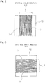
- the receiving surface of the one-dimensional detector 10 is located at the focal point of the focused secondary X-rays 42 (a state shown in Fig. 1 ), and the arrangement direction of the detection elements 7 coincides with the spectral angle direction of the spectroscopic device 6 as shown in Fig. 2 , as described above.
- the first detection element 7 to the 256th detection element 7 are linearly arranged in order starting from a position at which the spectral angle is smallest (a left side position in Fig. 2 , a diagonally upper side position in Fig. 1 .
- the receiving surface of the one-dimensional detector is viewed from the depth side of the drawing sheet in Fig. 1 , and thus the right side and the left side are inverted from those in Fig. 1 ), at intervals of 75 ⁇ m.
- a receiving slit 9 having an opening having a longitudinal direction orthogonal to the spectral angle direction of the spectroscopic device 6 is disposed at the focal point of the focused secondary X-rays 42, and the receiving surface of the one-dimensional detector 10 is located at the traveling direction side of the focused secondary X-rays 42 farther from the spectroscopic device 6 than the receiving slit 9 (in Fig. 4 , a portion, in the detector position change mechanism 11, at which the receiving slit 9 is disposed is shown as a cutaway view).
- the arrangement direction of the detection elements 7 intersects the spectral angle direction of the spectroscopic device 6 as shown in Fig. 3 .
- the spectrometer in Fig. 1 further includes: a measured spectrum display unit 14 that displays a relationship between positions, in the arrangement direction, of the detection elements 7, and detected intensities by the detection elements 7, as a measured spectrum, on a display 15; a detection area setting unit 16 that allows an operator to set, in the arrangement direction of the detection elements 7, a peak area that is an area of the detection elements 7 corresponding to fluorescent X-rays to be measured, and a plurality of background areas that are areas of the detection elements 7 corresponding to background of the fluorescent X-rays to be measured; and a quantification unit 17 that calculates, as a net intensity I net , an intensity of the fluorescent X-rays to be measured, based on a peak intensity obtained by integrating detected intensities by the detection elements 7 in the peak area, a background intensity obtained by integrating detected intensities by the detection elements 7 in each background area, and a background correction coefficient k which has been previously input, and that performs quantitative analysis, in a state where the one-dimensional detector 10 is set at
- the quantification unit 17 calculates an intensity of fluorescent X-rays to be measured, by integrating detected intensities by all the detection elements 7, and performs quantitative analysis.
- the measured spectrum display unit 14, the detection area setting unit 16, and the quantification unit 17 are included in a control unit 18 which is, for example, a computer and which controls the wavelength dispersive X-ray fluorescence spectrometer.
- the detector position change mechanism 11 has, for example, a rotation mechanism 12 that rotates the one-dimensional detector 10 about the optical axis of the focused secondary X-rays 42 and is operated manually or driven by a motor, and a slide mechanism 13 that slides the one-dimensional detector 10 in the optical axis direction of the focused secondary X-rays 42 and is operated manually or driven by a motor.
- the one-dimensional detector 10 is set at either the parallel position or the intersection position by using the detector position change mechanism 11.
- the detector position change mechanism 11 is not limited to a mechanism having the rotation mechanism 12 and the slide mechanism 13, and may be, for example, a screw cramping structure in which screw holes for mounting the one-dimensional detector 10 to the wavelength dispersive X-ray fluorescence spectrometer are provided at positions corresponding to the parallel position and the intersection position, respectively.
- intersection position in the present invention, a plurality of intersection positions having different intersection angles between the arrangement direction of the detection elements 7 and the spectral angle direction of the spectroscopic device 6 may be provided.
- the intersection position is either one of an orthogonal position at which the arrangement direction of the detection elements 7 is orthogonal to the spectral angle direction of the spectroscopic device 6, or a single oblique intersection position at which the arrangement direction of the detection elements 7 obliquely intersects the spectral angle direction of the spectroscopic device 6 at a predetermined angle (intersects the spectral angle direction of the spectroscopic device 6 at an angle other than a right angle).
- the intersection angle between the arrangement direction of the detection elements 7 and the spectral angle direction of the spectroscopic device 6 at the intersection position is preferably an angle at which the number of detection elements 7 on which the focused secondary X-rays 42 are incident is the largest and at which, of the projected area of the focused secondary X-rays 42 on a plane including (spreading so as to include) the receiving surface of the one-dimensional detector 10, the projected area of a portion protruding from the receiving surface of the one-dimensional detector 10 is the smallest.
- the intersection position is preferably the orthogonal position as shown in Fig. 5 .
- the first detection element 7 to the 256th detection element 7 are arranged, in order starting from the lower side or the upper side in Fig. 3 , in a direction orthogonal to the spectral angle direction of the spectroscopic device 6.
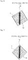
- the intersection position is preferably the oblique intersection position as shown in Figs. 6 to 8 , and, preferably, the projection image 19 of the focused secondary X-rays 42 on the plane including the receiving surface of the one-dimensional detector 10 does not protrude from the receiving surface and is nearly in contact with the edge thereof as shown in Figs. 6 and 7 , or a protruding portion of the projection image 19 is made the smallest as shown in Fig. 8 .
- the detection elements 7 of which the number is made smaller than that in Figs. 2 and 3 are shown in Figs. 5 to 8 .
- the one-dimensional detector 10 can be set at an optimum position for the relationship with the projection image 19 of the focused secondary X-rays 42 on the receiving surface.
- the intensity of the focused secondary X-rays can be detected at the maximum, and high-precision principal component analysis can be performed at a higher counting rate.
- the intersection position may be a diagonal line position at which a diagonal line direction of the receiving surface of the one-dimensional detector 10 is orthogonal to the spectral angle direction of the spectroscopic device 6, instead of the intersection position being either one of the orthogonal position or the single oblique intersection position as described above.
- the intersection position is the diagonal line position at which the intensity of the focused secondary X-rays can be efficiently detected in many cases, and thus high-precision principal component analysis can be performed at a high counting rate with a simpler structure.
- the arrangement direction of the detection elements 7 coincides with the spectral angle direction of the spectroscopic device 6, and the first detection element 7 to the 256th detection element 7 are linearly arranged in order starting from a position at which the spectral angle is smallest (a left side position in Fig. 9 ), at intervals of 75 ⁇ m as shown in Fig. 9 .
- the spectrometer of the present embodiment includes the measured spectrum display unit 14, which is not an essential component in the present invention.
- the measured spectrum display unit 14 is used together with the detection area setting unit 16.
- the measured spectrum display unit 14 displays the measured spectrum shown in Fig. 10 on the display 15.
- Fig. 10 measured spectra of a sample S that contains a large amount of element to be measured, and a blank sample S are displayed so as to overlay each other.
- the intensity of the sample S that contains the large amount of element to be measured is indicated so as to be reduced, in order to facilitate comparison between the overlaying spectra.
- the abscissa axis represents positions of the detection elements 7 in the arrangement direction thereof, and may represent the detection element numbers, spectral angles of the spectroscopic device 6, or energy values (the same applies to Figs. 11 and 12 ).
- the ordinate axis represents detected intensities by the detection elements 7.
- the spectrum PS of fluorescent X-rays measured from the sample S that contains the large amount of element to be measured is represented by a broken line, and the background spectrum BS measured from the blank sample S is represented by a solid line.
- a peak area PA, a first background area BA 1 , and a second background area BA 2 are displayed in the abscissa axis direction.
- an area size of a portion that is less than or equal to each spectrum PS, BS corresponds to a detected intensity that is detected by the detection elements 7 in each area BA 1 , PA, BA 2 for the sample S corresponding to the spectrum PS, BS.
- a detected intensity I P detected by the detection elements 7 in the peak area PA can be read.
- a detected intensity I B1 detected by the detection elements 7 in the first background area BA 1 a detected intensity I B detected by the detection elements 7 in the peak area PA, and a detected intensity I B2 detected by the detection elements 7 in the second background area BA 2 can be read.
- Each spectrum PS, BS and each area BA 1 , PA, BA 2 in the abscissa axis direction are displayed on the display 15 by the measured spectrum display unit 14, and a portion corresponding to each detected intensity described above is not necessarily displayed.
- An operator performs setting based on the displayed measured spectra by using the detection area setting unit 16 such that, for example, the 123-rd to the 129-th detection elements 7 are set for measuring an intensity of fluorescent X-rays in the peak area PA, the 106-th to the 112-nd detection elements 7 are set for measuring background in the first background area BA 1 , and the 140-th to the 146-th detection elements 7 are set for measuring background in the second background area BA 2 .
- the setting of the detection elements 7 is stored in the detection area setting unit 16.
- the optimal peak area PA and the optimal background areas BA 1 and BA 2 can be set based on the displayed measured spectra.
- a peak area PA and background areas BA 1 and BA 2 may be set from the detection area setting unit 16, for example, based on measured spectra measured by another wavelength dispersive X-ray fluorescence spectrometer of the same type, without using the measured spectrum display unit 14.
- the intensity of the secondary X-rays 41 (the center in Fig. 9 ) in which a spectral angle is an angle ⁇ , is detected by the detection elements 7 in the peak area PA
- the intensity of the secondary X-rays 41 (the left side in Fig. 9 ) in which a spectral angle is less than the spectral angle ⁇ , is detected by the detection elements 7 in the first background area BA 1
- the intensity of the secondary X-rays 41 (the right side in Fig. 9 ) in which the spectral angle is greater than the spectral angle ⁇ is detected by the detection elements 7 in the second background area BA 2 .
- three lines, of the focused secondary X-rays 42 which are different from each other in spectral angle as described above, are represented as the secondary X-rays 41 on the optical axes thereof.
- the quantification unit 17 When an analytical sample S has been measured, the quantification unit 17 appropriately subtracts the background intensity I B in the peak area from the peak intensity I P and calculates a net intensity I net of the fluorescent X-rays to be measured, based on equation (1) and equation (2) described below, to perform quantitative analysis.
- the background correction coefficient k may be calculated simultaneously when calibration curve constants are obtained by regression calculation, by using a calibration curve equation of the following equation (4).
- W A I P ⁇ k I B 1 + I B 2 + B
- measurement is performed in the two background areas BA1 and BA2, to correct (remove) background.
- the measurement may be performed in one or three or more background areas BA.
- the number of the detection elements 7 is set such that the number of the detection elements 7 in the peak area PA, the number of the detection elements 7 in the first background area BA1, and the number of the detection elements 7 in the second background area BA2 are the same.
- the numbers may be different.
- a measured spectrum shown in Fig. 11 of one sample S, from which a spectrum of fluorescent X-rays to be measured and a background spectrum can be observed may be used.
- the detected intensity I B1 detected by the detection elements 7 in the first background area BA 1 , the detected intensity I P detected by the detection elements 7 in the peak area PA, and the detected intensity I B2 detected by the detection elements 7 in the second background area BA 2 can be read.
- the quantification unit 17 calculates an intensity of fluorescent X-rays to be measured, by integrating detected intensities by all the detection elements 7, and performs quantitative analysis.
- the maximum counting rate of one detection element 7 is, for example, 1 Mcps.
- measurement can be performed at a counting rate up to 256 Mcps.
- An actually measured intensity is at most about 20 Mcps, and thus there is a margin that is greater than ten times of 20 Mcps.
- an intensity of fluorescent X-rays to be measured is calculated by integrating detected intensities by all the detection elements 7, whereby high-precision principal component analysis can be performed at a high counting rate.
- the wavelength dispersive X-ray fluorescence spectrometer of the present embodiment includes: the detector position change mechanism 11 for setting the position of the one-dimensional detector 10 such that the position of the one-dimensional detector 10 is freely changed to either the parallel position at which the arrangement direction of the detection elements 7 coincides with the spectral angle direction of the spectroscopic device 6 or the intersection position at which the arrangement direction of the detection elements 7 intersects the spectral angle direction of the spectroscopic device 6, and thus can quickly perform, with a simple structure, both high-precision quantitative analysis in which an accurate net intensity I net is obtained at a high speed and high-precision principal component analysis at a high counting rate.
Landscapes
- Physics & Mathematics (AREA)
- Health & Medical Sciences (AREA)
- Life Sciences & Earth Sciences (AREA)
- Chemical & Material Sciences (AREA)
- Analytical Chemistry (AREA)
- Biochemistry (AREA)
- General Health & Medical Sciences (AREA)
- General Physics & Mathematics (AREA)
- Immunology (AREA)
- Pathology (AREA)
- Spectroscopy & Molecular Physics (AREA)
- Analysing Materials By The Use Of Radiation (AREA)
Abstract
Description
- This application is based on and claims Convention priority to Japanese patent application No.
2016-194356, filed September 30, 2016 - The present invention relates to a wavelength dispersive X-ray fluorescence spectrometer including a focusing optical system.
- In X-ray fluorescence analysis, background of fluorescent X-rays generated from a sample irradiated with primary X-rays needs to be accurately corrected in order to precisely measure trace elements contained in the sample. Therefore, a wavelength dispersive X-ray fluorescence spectrometer having a focusing optical system, which: performs monochromating by using a single spectroscopic device; has a receiving slit disposed in front of a single detector and having a plurality of openings adjacent to each other; changes the opening through which secondary X-rays pass; and corrects background of fluorescent X-rays from a sample, is known (Patent Document 1). This focusing optical system is used as a fixed optical system, and is thus used for an X-ray fluorescence spectrometer specific to a single element or a simultaneous multi-elements analysis type X-ray fluorescence spectrometer in general.
- In many cases, as shown in
Fig. 12 that schematically illustrates a fluorescent X-ray spectrum PS and a background spectrum BS, in a peak area PA in which the spectrum PS of fluorescent X-rays occurs and in adjacent areas of peak BA, the background spectrum BS changes approximately linearly. In general, in a sequential X-ray fluorescence spectrometer, when a goniometer is moved to an adjacent area of peak to measure a background intensity, it is assumed that the background intensity can be measured with almost the same sensitivity between the peak area and the adjacent area of peak, and a net intensity is obtained by subtracting a background measured intensity from a peak measured intensity. - Meanwhile, as in the spectrometer disclosed in
Patent Document 1, in a wavelength dispersive X-ray fluorescence spectrometer of a focusing optical system in which a spectroscopic device and a detector are fixed, a receiving slit which is disposed in front of a single detector and which has a plurality of openings adjacent to each other is provided, and an opening through which secondary X-rays pass is changed so as to correspond to an adjacent area of peak, to measure a background intensity. However, a sensitivity of background is lower than that in a peak area, and, thus, an intensity which is lower than a background intensity that actually occurs, is measured. Therefore, an accurate net intensity cannot be obtained merely by subtracting a background measured intensity in the adjacent area of peak from a peak measured intensity. - Therefore, a wavelength dispersive X-ray fluorescence spectrometer having a focusing optical system, which: has a plurality of spectroscopic devices and a unit for selecting an optical path of secondary X-rays incident on a single detector; switches a spectroscopic device to be used; measures a peak intensity and a background intensity with sensitivities that are assumed to be almost the same; and corrects background of fluorescent X-rays generated from a sample, is known. Furthermore, a spectrometer that has, instead of the optical path selection unit of the above spectrometer, a position sensitive detector as a detector, to simultaneously measure a peak intensity and a background intensity in a short time period, is also known (Patent Document 2).
- In principal component analysis in X-ray fluorescence analysis, high measurement accuracy is needed, and thus it is necessary to measure an element to be measured, at a high counting rate. However, with a conventional detector (a proportional counter, a scintillation counter, etc.), the counting upper limit at which counting linearity is obtained is about 1000 to 4000 kcps. Therefore, an attenuator exchange mechanism is provided, and, for example, when a metal sample containing a principal component element of which an X-ray intensity exceeds the counting upper limit is analyzed, a fluorescent X-ray intensity is decreased to be equal to or less than the counting upper limit, by using an attenuator. Alternatively, a fixed attenuator which attenuates an intensity, for a sample having a maximum content, such that the intensity does not exceed the counting upper limit is provided in some cases. In such a case, even for a low-content sample, an intensity is attenuated. Instead of using the attenuator, a tube voltage or a tube current to be supplied to an X-ray tube is decreased, and measurement is performed in some cases (for example, paragraph 0002 of Patent Document 3).
-
- [Patent Document 1]
JP Laid-open Patent Publication No. H08-128975 - [Patent Document 2]
WO 2004/086018 - [Patent Document 3]
JP Laid-open Patent Publication No. 2012-159404 - However, in the spectrometer disclosed in
Patent Document 2, a plurality of spectroscopic devices are provided in order to separately measure fluorescent X-rays and the background thereof, and, therefore, a problem arises that the structure of the spectrometer is complicated, cost is high, and a time required for assembling or alignment of the spectrometer is increased. - In principal component analysis, to decrease a fluorescent X-ray intensity using an attenuator such that the fluorescent X-ray intensity is equal to or less than the counting upper limit, or to decrease a tube voltage or a tube current to be supplied to an X-ray tube and perform measurement, it is necessary to set appropriate analysis conditions for each sample, and thus the measurement operations become complicated. In addition, due to the decrease of the X-ray intensity, a problem also arises that the measurement accuracy deteriorates.
- The present invention is made in view of the problems of the conventional art, and an object of the present invention is to provide a wavelength dispersive X-ray fluorescence spectrometer that can quickly perform, with a simple structure, both: high-precision quantitative analysis in which an accurate net intensity is obtained at a high speed; and high-precision principal component analysis at a high counting rate.
- In order to attain the aforementioned object, the present invention is directed to a wavelength dispersive X-ray fluorescence spectrometer of a focusing optical system, the wavelength dispersive X-ray fluorescence spectrometer comprising: an X-ray source configured to irradiate a sample with primary X-rays; a divergence slit configured to allow secondary X-rays generated from the sample to pass therethrough; a spectroscopic device configured to monochromate and focus the secondary X-rays that have passed through the divergence slit; and a single one-dimensional detector having a plurality of detection elements arranged linearly and having a receiving surface perpendicular to an optical axis of focused secondary X-rays obtained by the secondary X-rays being focused by the spectroscopic device, wherein the wavelength dispersive X-ray fluorescence spectrometer comprises a detector position change mechanism for setting a position of the one-dimensional detector such that the position of the one-dimensional detector is freely changed to either a parallel position at which an arrangement direction of the detection elements coincides with a spectral angle direction of the spectroscopic device or an intersection position at which the arrangement direction of the detection elements intersects the spectral angle direction of the spectroscopic device.
- In the present invention, in a state where the one-dimensional detector is set at the parallel position, the receiving surface of the one-dimensional detector is located at a focal point of the focused secondary X-rays; and in a state where the one-dimensional detector is set at the intersection position, a receiving slit having an opening having a longitudinal direction orthogonal to the spectral angle direction of the spectroscopic device is disposed at the focal point of the focused secondary X-rays, and the receiving surface of the one-dimensional detector is located at a traveling direction side of the focused secondary X-rays farther from the spectroscopic device than the receiving slit.
- According to the present invention, since the detector position change mechanism for changing the position of the one-dimensional detector such that the position of the one-dimensional detector is freely changed to either the parallel position at which the arrangement direction of the detection elements coincides with the spectral angle direction of the spectroscopic device or the intersection position at which the arrangement direction of the detection elements intersects the spectral angle direction of the spectroscopic device, is included, both high-precision quantitative analysis in which an accurate net intensity is obtained at a high speed and high-precision principal component analysis at a high counting rate can be quickly performed with a simple structure.
- In the present invention, the wavelength dispersive X-ray fluorescence spectrometer preferably includes: a detection area setting unit configured to allow for setting a peak area that is an area of the detection elements corresponding to fluorescent X-rays to be measured, and a plurality of background areas that are areas of the detection elements corresponding to background of the fluorescent X-rays to be measured, in the arrangement direction of the detection elements; and a quantification unit configured to calculate, as a net intensity, an intensity of the fluorescent X-rays to be measured, based on a peak intensity obtained by integrating detected intensities by the detection elements in the peak area, a background intensity obtained by integrating detected intensities by the detection elements in each background area, and a background correction coefficient which is previously input, and to perform quantitative analysis, in a state where the one-dimensional detector is set at the parallel position. In this case, background which is measured so as to indicate an intensity lower than a background intensity that actually occurs is accurately corrected, and the peak intensity and the background intensities are simultaneously measured. Thus, high-precision quantitative analysis in which an accurate net intensity is obtained at a high speed can be performed.
- In the present invention, the wavelength dispersive X-ray fluorescence spectrometer preferably includes a quantification unit configured to calculate an intensity of fluorescent X-rays to be measured, by integrating detected intensities by all the detection elements, and to perform quantitative analysis, in a state where the one-dimensional detector is set at the intersection position. In this case, an intensity of fluorescent X-rays to be measured is calculated by integrating detected intensities by all the detection elements, whereby high-precision principal component analysis can be performed at a high counting rate.
- In the present invention, the intersection position is preferably either one of an orthogonal position at which the arrangement direction of the detection elements is orthogonal to the spectral angle direction of the spectroscopic device or a single oblique intersection position at which the arrangement direction of the detection elements obliquely intersects the spectral angle direction of the spectroscopic device at a predetermined angle. In this case, the intersection position is either one of the orthogonal position or the single oblique intersection position, and the one-dimensional detector can be set at an optimum position for the relationship with a projection image of the focused secondary X-rays on the receiving surface. Thus, the intensity of the focused secondary X-rays can be detected at the maximum, and high-precision principal component analysis can be performed at a higher counting rate.
- In the present invention, preferably, the receiving surface of the one-dimensional detector is rectangular, and the intersection position is a diagonal line position at which a diagonal line direction of the receiving surface of the one-dimensional detector is orthogonal to the spectral angle direction of the spectroscopic device. In this case, the intersection position is the diagonal line position at which the intensity of the focused secondary X-rays can be efficiently detected in many cases, and thus high-precision principal component analysis can be performed at a high counting rate with a simpler structure.
- Any combination of at least two constructions, disclosed in the appended claims and/or the specification and/or the accompanying drawings should be construed as included within the scope of the present invention. In particular, any combination of two or more of the appended claims should be equally construed as included within the scope of the present invention.
- In any event, the present invention will become more clearly understood from the following description of preferred embodiments thereof, when taken in conjunction with the accompanying drawings. However, the embodiments and the drawings are given only for the purpose of illustration and explanation, and are not to be taken as limiting the scope of the present invention in any way whatsoever, which scope is to be determined by the appended claims. In the accompanying drawings, like reference numerals are used to denote like parts throughout the several views, and:
-
Fig. 1 is a schematic diagram illustrating a wavelength dispersive X-ray fluorescence spectrometer according to an embodiment of the present invention; -
Fig. 2 is a diagram illustrating a receiving surface of a one-dimensional detector that is set at a parallel position; -
Fig. 3 is a diagram illustrating the receiving surface of the one-dimensional detector that is set at an intersection position that is an orthogonal position; -
Fig. 4 is a diagram illustrating a receiving slit and the one-dimensional detector that is set at the intersection position; -
Fig. 5 is a diagram illustrating a projection image of focused secondary X-rays and arrangement of detection elements at the intersection position that is the orthogonal position; -
Fig. 6 is a diagram illustrating the projection image of the focused secondary X-rays and arrangement of the detection elements at the intersection position that is an oblique intersection position; -
Fig. 7 is a diagram illustrating the projection image of the focused secondary X-rays and arrangement of the detection elements at the intersection position that is a diagonal line position and is the oblique intersection position; -
Fig. 8 is another diagram illustrating the projection image of the focused secondary X-rays and arrangement of the detection elements at the intersection position that is the diagonal line position and is the oblique intersection position; -
Fig. 9 is a diagram illustrating the detection elements in a peak area and background areas in the one-dimensional detector that is set at the parallel position; -
Fig. 10 is a diagram illustrating a peak area and background areas of a spectrum in which measured spectra of a blank sample and a sample that contains a large amount of element to be measured overlaid each other; -
Fig. 11 is a diagram illustrating a peak measurement area and background measurement areas of a measured spectrum of one sample; and -
Fig. 12 schematically illustrates a spectrum of fluorescent X-rays and a background spectrum. - Hereinafter, a wavelength dispersive X-ray fluorescence spectrometer according to an embodiment of the present invention will be described with reference to the drawings. As shown in
Fig. 1 , the spectrometer is a wavelength dispersive X-ray fluorescence spectrometer of a focusing optical system, which includes: anX-ray source 2 that irradiates a sample S withprimary X-rays 1; a divergence slit 5 that allowssecondary X-rays 4 generated from the sample S to pass therethrough; aspectroscopic device 6 that monochromates and focuses thesecondary X-rays 4 that have passed through the divergence slit 5; and a single one-dimensional detector 10 that has a plurality ofdetection elements 7 arranged linearly (seeFigs. 2 and 3 ) and has a receiving surface perpendicular to an optical axis of focusedsecondary X-rays 42 obtained by thesecondary X-rays 4 being focused by thespectroscopic device 6. The wavelength dispersive X-ray fluorescence spectrometer includes a detectorposition change mechanism 11 that sets a position of the one-dimensional detector 10 such that the position of the one-dimensional detector 10 is freely changed to either a parallel position at which an arrangement direction of thedetection elements 7 coincides with a spectral angle direction of thespectroscopic device 6, or an intersection position at which the arrangement direction of thedetection elements 7 intersects the spectral angle direction of thespectroscopic device 6. - In a state where the one-
dimensional detector 10 is set at the parallel position, the receiving surface of the one-dimensional detector 10 is located at the focal point of the focused secondary X-rays 42 (a state shown inFig. 1 ), and the arrangement direction of thedetection elements 7 coincides with the spectral angle direction of thespectroscopic device 6 as shown inFig. 2 , as described above. For example, thefirst detection element 7 to the256th detection element 7 are linearly arranged in order starting from a position at which the spectral angle is smallest (a left side position inFig. 2 , a diagonally upper side position inFig. 1 . InFigs. 2 and9 , the receiving surface of the one-dimensional detector is viewed from the depth side of the drawing sheet inFig. 1 , and thus the right side and the left side are inverted from those inFig. 1 ), at intervals of 75 µm. - In a state where the one-
dimensional detector 10 is set at the intersection position, as shown inFig. 4 , a receivingslit 9 having an opening having a longitudinal direction orthogonal to the spectral angle direction of thespectroscopic device 6 is disposed at the focal point of the focusedsecondary X-rays 42, and the receiving surface of the one-dimensional detector 10 is located at the traveling direction side of the focusedsecondary X-rays 42 farther from thespectroscopic device 6 than the receiving slit 9 (inFig. 4 , a portion, in the detectorposition change mechanism 11, at which the receiving slit 9 is disposed is shown as a cutaway view). In addition, as described above, the arrangement direction of thedetection elements 7 intersects the spectral angle direction of thespectroscopic device 6 as shown inFig. 3 . - The spectrometer in
Fig. 1 further includes: a measuredspectrum display unit 14 that displays a relationship between positions, in the arrangement direction, of thedetection elements 7, and detected intensities by thedetection elements 7, as a measured spectrum, on adisplay 15; a detectionarea setting unit 16 that allows an operator to set, in the arrangement direction of thedetection elements 7, a peak area that is an area of thedetection elements 7 corresponding to fluorescent X-rays to be measured, and a plurality of background areas that are areas of thedetection elements 7 corresponding to background of the fluorescent X-rays to be measured; and aquantification unit 17 that calculates, as a net intensity Inet, an intensity of the fluorescent X-rays to be measured, based on a peak intensity obtained by integrating detected intensities by thedetection elements 7 in the peak area, a background intensity obtained by integrating detected intensities by thedetection elements 7 in each background area, and a background correction coefficient k which has been previously input, and that performs quantitative analysis, in a state where the one-dimensional detector 10 is set at the parallel position. - In a state where the one-
dimensional detector 10 is set at the intersection position, thequantification unit 17 calculates an intensity of fluorescent X-rays to be measured, by integrating detected intensities by all thedetection elements 7, and performs quantitative analysis. The measuredspectrum display unit 14, the detectionarea setting unit 16, and thequantification unit 17 are included in acontrol unit 18 which is, for example, a computer and which controls the wavelength dispersive X-ray fluorescence spectrometer. - The detector
position change mechanism 11 has, for example, arotation mechanism 12 that rotates the one-dimensional detector 10 about the optical axis of the focusedsecondary X-rays 42 and is operated manually or driven by a motor, and aslide mechanism 13 that slides the one-dimensional detector 10 in the optical axis direction of the focusedsecondary X-rays 42 and is operated manually or driven by a motor. The one-dimensional detector 10 is set at either the parallel position or the intersection position by using the detectorposition change mechanism 11. The detectorposition change mechanism 11 is not limited to a mechanism having therotation mechanism 12 and theslide mechanism 13, and may be, for example, a screw cramping structure in which screw holes for mounting the one-dimensional detector 10 to the wavelength dispersive X-ray fluorescence spectrometer are provided at positions corresponding to the parallel position and the intersection position, respectively. - Regarding the intersection position, in the present invention, a plurality of intersection positions having different intersection angles between the arrangement direction of the
detection elements 7 and the spectral angle direction of thespectroscopic device 6 may be provided. However, in the spectrometer of the present embodiment, the intersection position is either one of an orthogonal position at which the arrangement direction of thedetection elements 7 is orthogonal to the spectral angle direction of thespectroscopic device 6, or a single oblique intersection position at which the arrangement direction of thedetection elements 7 obliquely intersects the spectral angle direction of thespectroscopic device 6 at a predetermined angle (intersects the spectral angle direction of thespectroscopic device 6 at an angle other than a right angle). - Here, at the intersection position, the intersection angle between the arrangement direction of the
detection elements 7 and the spectral angle direction of thespectroscopic device 6 at the intersection position is preferably an angle at which the number ofdetection elements 7 on which the focusedsecondary X-rays 42 are incident is the largest and at which, of the projected area of the focusedsecondary X-rays 42 on a plane including (spreading so as to include) the receiving surface of the one-dimensional detector 10, the projected area of a portion protruding from the receiving surface of the one-dimensional detector 10 is the smallest. - For example, in a spectroscopic system for which the position of the one-
dimensional detector 10 is to be set, when the length (the dimension in the longitudinal direction) of aprojection image 19 of the focusedsecondary X-rays 42 on the plane including the receiving surface of the one-dimensional detector 10 is equal to or less than the length of the receiving surface in the arrangement direction of thedetection elements 7, the intersection position is preferably the orthogonal position as shown inFig. 5 . In a state where the one-dimensional detector 10 is set at the orthogonal position, as shown inFig. 3 , thefirst detection element 7 to the256th detection element 7 are arranged, in order starting from the lower side or the upper side inFig. 3 , in a direction orthogonal to the spectral angle direction of thespectroscopic device 6. - For example, in the spectroscopic system for which the position of the one-
dimensional detector 10 is to be set, when the length of theprojection image 19 of the focusedsecondary X-rays 42 on the plane including the receiving surface of the one-dimensional detector 10 is longer than the length of the receiving surface in the arrangement direction of thedetection elements 7, the intersection position is preferably the oblique intersection position as shown inFigs. 6 to 8 , and, preferably, theprojection image 19 of the focusedsecondary X-rays 42 on the plane including the receiving surface of the one-dimensional detector 10 does not protrude from the receiving surface and is nearly in contact with the edge thereof as shown inFigs. 6 and 7 , or a protruding portion of theprojection image 19 is made the smallest as shown inFig. 8 . For the sake of easy illustration and understanding, thedetection elements 7 of which the number is made smaller than that inFigs. 2 and 3 are shown inFigs. 5 to 8 . - As described above, when the intersection position is either one of the orthogonal position or the single oblique intersection position, the one-
dimensional detector 10 can be set at an optimum position for the relationship with theprojection image 19 of the focusedsecondary X-rays 42 on the receiving surface. Thus, the intensity of the focused secondary X-rays can be detected at the maximum, and high-precision principal component analysis can be performed at a higher counting rate. - In the case where the receiving surface of the one-
dimensional detector 10 is rectangular, the intersection position may be a diagonal line position at which a diagonal line direction of the receiving surface of the one-dimensional detector 10 is orthogonal to the spectral angle direction of thespectroscopic device 6, instead of the intersection position being either one of the orthogonal position or the single oblique intersection position as described above. In this case, the intersection position is the diagonal line position at which the intensity of the focused secondary X-rays can be efficiently detected in many cases, and thus high-precision principal component analysis can be performed at a high counting rate with a simpler structure. - Next, operation of the spectrometer of the present embodiment in a state where the one-
dimensional detector 10 is set at the parallel position will be described. When the one-dimensional detector 10 is set at the parallel position, the arrangement direction of thedetection elements 7 coincides with the spectral angle direction of thespectroscopic device 6, and thefirst detection element 7 to the256th detection element 7 are linearly arranged in order starting from a position at which the spectral angle is smallest (a left side position inFig. 9 ), at intervals of 75 µm as shown inFig. 9 . - The spectrometer of the present embodiment includes the measured
spectrum display unit 14, which is not an essential component in the present invention. When an operator sets a peak area and background areas, the measuredspectrum display unit 14 is used together with the detectionarea setting unit 16. For example, the measuredspectrum display unit 14 displays the measured spectrum shown inFig. 10 on thedisplay 15. - In
Fig. 10 , measured spectra of a sample S that contains a large amount of element to be measured, and a blank sample S are displayed so as to overlay each other. The intensity of the sample S that contains the large amount of element to be measured is indicated so as to be reduced, in order to facilitate comparison between the overlaying spectra. For this measured spectrum, the abscissa axis represents positions of thedetection elements 7 in the arrangement direction thereof, and may represent the detection element numbers, spectral angles of thespectroscopic device 6, or energy values (the same applies toFigs. 11 and12 ). The ordinate axis represents detected intensities by thedetection elements 7. The spectrum PS of fluorescent X-rays measured from the sample S that contains the large amount of element to be measured is represented by a broken line, and the background spectrum BS measured from the blank sample S is represented by a solid line. A peak area PA, a first background area BA1, and a second background area BA2 are displayed in the abscissa axis direction. - In
Fig. 10 , in each area BA1, PA, BA2, an area size of a portion that is less than or equal to each spectrum PS, BS (a portion between each spectrum PS, BS and the abscissa axis, three black bar-like portions in the spectrum BS, a portion obtained by further extending the central black bar-like portion with the broken line for the spectrum PS) corresponds to a detected intensity that is detected by thedetection elements 7 in each area BA1, PA, BA2 for the sample S corresponding to the spectrum PS, BS. InFig. 10 , for the sample S that contains the large amount of element to be measured, a detected intensity IP detected by thedetection elements 7 in the peak area PA can be read. For the blank sample S, a detected intensity IB1 detected by thedetection elements 7 in the first background area BA1, a detected intensity IB detected by thedetection elements 7 in the peak area PA, and a detected intensity IB2 detected by thedetection elements 7 in the second background area BA2 can be read. Each spectrum PS, BS and each area BA1, PA, BA2 in the abscissa axis direction are displayed on thedisplay 15 by the measuredspectrum display unit 14, and a portion corresponding to each detected intensity described above is not necessarily displayed. - An operator performs setting based on the displayed measured spectra by using the detection
area setting unit 16 such that, for example, the 123-rd to the 129-th detection elements 7 are set for measuring an intensity of fluorescent X-rays in the peak area PA, the 106-th to the 112-nd detection elements 7 are set for measuring background in the first background area BA1, and the 140-th to the 146-th detection elements 7 are set for measuring background in the second background area BA2. The setting of thedetection elements 7 is stored in the detectionarea setting unit 16. Thus, the optimal peak area PA and the optimal background areas BA1 and BA2 can be set based on the displayed measured spectra. A peak area PA and background areas BA1 and BA2 may be set from the detectionarea setting unit 16, for example, based on measured spectra measured by another wavelength dispersive X-ray fluorescence spectrometer of the same type, without using the measuredspectrum display unit 14. - When the peak area PA, the first background area BA1, and the second background area BA2 are set in the detection
area setting unit 16, the intensity of the secondary X-rays 41 (the center inFig. 9 ) in which a spectral angle is an angle θ, is detected by thedetection elements 7 in the peak area PA, the intensity of the secondary X-rays 41 (the left side inFig. 9 ) in which a spectral angle is less than the spectral angle θ, is detected by thedetection elements 7 in the first background area BA1, and the intensity of the secondary X-rays 41 (the right side inFig. 9 ) in which the spectral angle is greater than the spectral angle θ is detected by thedetection elements 7 in the second background area BA2. InFig. 9 , three lines, of the focusedsecondary X-rays 42, which are different from each other in spectral angle as described above, are represented as thesecondary X-rays 41 on the optical axes thereof. - When an analytical sample S has been measured, the
quantification unit 17 appropriately subtracts the background intensity IB in the peak area from the peak intensity IP and calculates a net intensity Inet of the fluorescent X-rays to be measured, based on equation (1) and equation (2) described below, to perform quantitative analysis.

- Inet: calculated net intensity of fluorescent X-rays to be measured
- IP: peak intensity obtained by integrating detected intensities by detection elements (the 123-rd to the 129-th detection elements) in peak area
- IB: background intensity in peak area
- IB1: background intensity obtained by integrating detected intensities by detection elements (the 106-th to the 112-nd detection elements) in first background area
- IB2: background intensity obtained by integrating detected intensities by detection elements (the 140-th to the 146-th detection elements) in second background area
- k: background correction coefficient
- The background correction coefficient k is previously obtained based on the following equation (3) by measuring the blank sample S and is input into the
quantification unit 17.
- IB B: peak intensity, of blank sample, obtained by integrating detected intensities by detection elements (the 123-rd to the 129-th detection elements) in peak area
- IB1 B: background intensity, of blank sample, obtained by integrating detected intensities by detection elements (the 106-th to the 112-th detection elements) in first background area
- IB2 B: background intensity, of blank sample, obtained by integrating detected intensities by detection elements (the 140-th to the 146-th detection elements) in second background area
- The background correction coefficient k may be calculated simultaneously when calibration curve constants are obtained by regression calculation, by using a calibration curve equation of the following equation (4).

- W: content of element, to be measured, in sample
- A, B: calibration curve constants
- As described above, in the spectrometer of the present embodiment, in a state where the one-
dimensional detector 10 is set at the parallel position, background which is measured so as to indicate an intensity lower than a background intensity that actually occurs is accurately corrected, and the peak intensity IP and the background intensities IB1 and IB2 are simultaneously measured. Thus, high-precision quantitative analysis in which an accurate net intensity Inet is obtained at a high speed can be performed. - In the example described above, measurement is performed in the two background areas BA1 and BA2, to correct (remove) background. However, the measurement may be performed in one or three or more background areas BA. In the example described above, the number of the
detection elements 7 is set such that the number of thedetection elements 7 in the peak area PA, the number of thedetection elements 7 in the first background area BA1, and the number of thedetection elements 7 in the second background area BA2 are the same. However, the numbers may be different. - Instead of the above-described measured spectrum in which the measured spectra of the blank sample S and the sample S that contains the large amount of element to be measured overlaid each other, a measured spectrum shown in
Fig. 11 , of one sample S, from which a spectrum of fluorescent X-rays to be measured and a background spectrum can be observed may be used. InFig. 11 , for the one sample S, the detected intensity IB1 detected by thedetection elements 7 in the first background area BA1, the detected intensity IP detected by thedetection elements 7 in the peak area PA, and the detected intensity IB2 detected by thedetection elements 7 in the second background area BA2, can be read. - Next, operation of the spectrometer of the present embodiment in a state where the one-
dimensional detector 10 is set at the intersection position will be described. When the one-dimensional detector 10 is set at the intersection position, the arrangement direction of thedetection elements 7 intersects the spectral angle direction of thespectroscopic device 6. Thequantification unit 17 calculates an intensity of fluorescent X-rays to be measured, by integrating detected intensities by all thedetection elements 7, and performs quantitative analysis. The maximum counting rate of onedetection element 7 is, for example, 1 Mcps. Thus, when a one-dimensional detector 10 having 256detection elements 7 is used, measurement can be performed at a counting rate up to 256 Mcps. An actually measured intensity is at most about 20 Mcps, and thus there is a margin that is greater than ten times of 20 Mcps. - As described above, in the spectrometer of the present embodiment, in a state where the one-
dimensional detector 10 is set at the intersection position, an intensity of fluorescent X-rays to be measured is calculated by integrating detected intensities by all thedetection elements 7, whereby high-precision principal component analysis can be performed at a high counting rate. - As described above, the wavelength dispersive X-ray fluorescence spectrometer of the present embodiment includes: the detector
position change mechanism 11 for setting the position of the one-dimensional detector 10 such that the position of the one-dimensional detector 10 is freely changed to either the parallel position at which the arrangement direction of thedetection elements 7 coincides with the spectral angle direction of thespectroscopic device 6 or the intersection position at which the arrangement direction of thedetection elements 7 intersects the spectral angle direction of thespectroscopic device 6, and thus can quickly perform, with a simple structure, both high-precision quantitative analysis in which an accurate net intensity Inet is obtained at a high speed and high-precision principal component analysis at a high counting rate. - Although the present invention has been fully described in connection with the preferred embodiments thereof with reference to the accompanying drawings which are used only for the purpose of illustration, those skilled in the art will readily conceive numerous changes and modifications within the framework of obviousness upon the reading of the specification herein presented of the present invention. Accordingly, such changes and modifications are, unless they depart from the scope of the present invention as delivered from the claims annexed hereto, to be construed as included therein.
-
- 1
- primary X-rays
- 2
- X-ray source
- 4
- secondary X-rays
- 5
- divergence slit
- 6
- spectroscopic device
- 7
- detection element
- 9
- receiving slit
- 10
- one-dimensional detector
- 11
- detector position change mechanism
- 16
- detection area setting unit
- 17
- quantification unit
- 42
- focused secondary X-rays
- BA1, BA2
- background area
- PA
- peak area
- S
- sample
Claims (5)
- A wavelength dispersive X-ray fluorescence spectrometer of a focusing optical system, the wavelength dispersive X-ray fluorescence spectrometer comprising:an X-ray source configured to irradiate a sample with primary X-rays;a divergence slit configured to allow secondary X-rays generated from the sample to pass therethrough;a spectroscopic device configured to monochromate and focus the secondary X-rays that have passed through the divergence slit; anda single one-dimensional detector having a plurality of detection elements arranged linearly and having a receiving surface perpendicular to an optical axis of focused secondary X-rays obtained by the secondary X-rays being focused by the spectroscopic device, whereinthe wavelength dispersive X-ray fluorescence spectrometer comprises a detector position change mechanism for setting a position of the one-dimensional detector such that the position of the one-dimensional detector is freely changed to either a parallel position at which an arrangement direction of the detection elements coincides with a spectral angle direction of the spectroscopic device or an intersection position at which the arrangement direction of the detection elements intersects the spectral angle direction of the spectroscopic device,in a state where the one-dimensional detector is set at the parallel position, the receiving surface of the one-dimensional detector is located at a focal point of the focused secondary X-rays, andin a state where the one-dimensional detector is set at the intersection position, a receiving slit having an opening having a longitudinal direction orthogonal to the spectral angle direction of the spectroscopic device is disposed at the focal point of the focused secondary X-rays, and the receiving surface of the one-dimensional detector is located at a traveling direction side of the focused secondary X-rays farther from the spectroscopic device than the receiving slit.
- The wavelength dispersive X-ray fluorescence spectrometer as claimed in claim 1, further comprising:a detection area setting unit configured to allow for setting a peak area that is an area of the detection elements corresponding to fluorescent X-rays to be measured, and a plurality of background areas that are areas of the detection elements corresponding to background of the fluorescent X-rays to be measured, in the arrangement direction of the detection elements; anda quantification unit configured to calculate, as a net intensity, an intensity of the fluorescent X-rays to be measured, based on a peak intensity obtained by integrating detected intensities by the detection elements in the peak area, a background intensity obtained by integrating detected intensities by the detection elements in each background area, and a background correction coefficient which is previously input, and to perform quantitative analysis, in a state where the one-dimensional detector is set at the parallel position.
- The wavelength dispersive X-ray fluorescence spectrometer as claimed in claim 1, further comprising a quantification unit configured to calculate an intensity of fluorescent X-rays to be measured, by integrating detected intensities by all the detection elements, and to perform quantitative analysis, in a state where the one-dimensional detector is set at the intersection position.
- The wavelength dispersive X-ray fluorescence spectrometer as claimed in any one of claims 1 to 3, wherein the intersection position is either one of an orthogonal position at which the arrangement direction of the detection elements is orthogonal to the spectral angle direction of the spectroscopic device or a single oblique intersection position at which the arrangement direction of the detection elements obliquely intersects the spectral angle direction of the spectroscopic device at a predetermined angle.
- The wavelength dispersive X-ray fluorescence spectrometer as claimed in any one of claims 1 to 3, wherein
the receiving surface of the one-dimensional detector is rectangular, and
the intersection position is a diagonal line position at which a diagonal line direction of the receiving surface of the one-dimensional detector is orthogonal to the spectral angle direction of the spectroscopic device.
Applications Claiming Priority (2)
| Application Number | Priority Date | Filing Date | Title |
|---|---|---|---|
| JP2016194356A JP6467600B2 (en) | 2016-09-30 | 2016-09-30 | Wavelength dispersive X-ray fluorescence analyzer |
| PCT/JP2017/031494 WO2018061607A1 (en) | 2016-09-30 | 2017-08-31 | Wavelength-dispersive x-ray fluorescence analysis device |
Publications (3)
| Publication Number | Publication Date |
|---|---|
| EP3521813A1 true EP3521813A1 (en) | 2019-08-07 |
| EP3521813A4 EP3521813A4 (en) | 2020-06-24 |
| EP3521813B1 EP3521813B1 (en) | 2022-12-07 |
Family
ID=61760308
Family Applications (1)
| Application Number | Title | Priority Date | Filing Date |
|---|---|---|---|
| EP17855565.2A Active EP3521813B1 (en) | 2016-09-30 | 2017-08-31 | Wavelength dispersive x-ray fluorescence spectrometer |
Country Status (5)
| Country | Link |
|---|---|
| US (1) | US10948436B2 (en) |
| EP (1) | EP3521813B1 (en) |
| JP (1) | JP6467600B2 (en) |
| CN (1) | CN109791116B (en) |
| WO (1) | WO2018061607A1 (en) |
Families Citing this family (6)
| Publication number | Priority date | Publication date | Assignee | Title |
|---|---|---|---|---|
| JP6467600B2 (en) * | 2016-09-30 | 2019-02-13 | 株式会社リガク | Wavelength dispersive X-ray fluorescence analyzer |
| FI20206176A1 (en) * | 2018-04-20 | 2020-11-20 | Outotec Finland Oy | X-ray fluorescence analyzer system and method for performing X-ray fluorescence analysis to detect an element of interest in sludge |
| JP6962951B2 (en) * | 2019-03-08 | 2021-11-05 | 日本電子株式会社 | Analyzer and spectrum generation method |
| JP7100910B2 (en) * | 2020-12-01 | 2022-07-14 | 株式会社リガク | Total internal reflection fluorescent X-ray analyzer |
| JP7726044B2 (en) * | 2021-01-05 | 2025-08-20 | 株式会社島津製作所 | X-ray spectrometer and elemental analysis method |
| JP7845687B2 (en) * | 2023-01-31 | 2026-04-15 | 株式会社リガク | Detector base and X-ray diffractometer |
Family Cites Families (17)
| Publication number | Priority date | Publication date | Assignee | Title |
|---|---|---|---|---|
| JPS49118493A (en) | 1973-03-12 | 1974-11-12 | ||
| JPH05340897A (en) * | 1992-06-11 | 1993-12-24 | Shimadzu Corp | X-ray spectrometer |
| JP2685726B2 (en) * | 1994-10-31 | 1997-12-03 | 理学電機工業株式会社 | X-ray analyzer |
| CN1270176C (en) * | 2002-12-02 | 2006-08-16 | 中国科学技术大学 | Method and apparatus for measuring and analyzing structure and component of combined sample |
| CN1739023B (en) * | 2003-03-27 | 2012-01-04 | 株式会社理学 | Fluorescent X-ray Analysis Device |
| US7190762B2 (en) * | 2004-10-29 | 2007-03-13 | Broker Axs, Inc | Scanning line detector for two-dimensional x-ray diffractometer |
| JP4908119B2 (en) * | 2005-10-19 | 2012-04-04 | 株式会社リガク | X-ray fluorescence analyzer |
| US8283631B2 (en) * | 2008-05-08 | 2012-10-09 | Kla-Tencor Corporation | In-situ differential spectroscopy |
| RU2419088C1 (en) * | 2010-02-01 | 2011-05-20 | Учреждение Российской академии наук Физический институт им. П.Н. Лебедева РАН (ФИАН) | X-ray spectrometer |
| JP5441856B2 (en) * | 2010-09-10 | 2014-03-12 | 日本電子株式会社 | X-ray detection system |
| JP5412649B2 (en) | 2011-02-01 | 2014-02-12 | 株式会社リガク | X-ray fluorescence analyzer |
| WO2015056305A1 (en) * | 2013-10-15 | 2015-04-23 | 株式会社島津製作所 | X-ray fluorescence analysis method and x-ray fluorescence analysis device |
| JP6346036B2 (en) * | 2014-09-09 | 2018-06-20 | 株式会社日立ハイテクサイエンス | X-ray fluorescence analyzer and method for adjusting measurement position thereof |
| US9739730B2 (en) | 2015-03-03 | 2017-08-22 | Panalytical B.V. | Quantitative X-ray analysis—multi optical path instrument |
| JP6706932B2 (en) * | 2015-03-03 | 2020-06-10 | マルバーン パナリティカル ビー ヴィ | Quantitative X-ray analysis method and multi-optical path device |
| JP6467600B2 (en) * | 2016-09-30 | 2019-02-13 | 株式会社リガク | Wavelength dispersive X-ray fluorescence analyzer |
| JP6383018B2 (en) * | 2017-01-19 | 2018-08-29 | 本田技研工業株式会社 | X-ray diffraction measurement method and apparatus |
-
2016
- 2016-09-30 JP JP2016194356A patent/JP6467600B2/en active Active
-
2017
- 2017-08-31 CN CN201780059601.1A patent/CN109791116B/en active Active
- 2017-08-31 WO PCT/JP2017/031494 patent/WO2018061607A1/en not_active Ceased
- 2017-08-31 EP EP17855565.2A patent/EP3521813B1/en active Active
-
2019
- 2019-03-29 US US16/370,363 patent/US10948436B2/en active Active
Also Published As
| Publication number | Publication date |
|---|---|
| US20190227008A1 (en) | 2019-07-25 |
| CN109791116B (en) | 2021-06-18 |
| CN109791116A (en) | 2019-05-21 |
| EP3521813B1 (en) | 2022-12-07 |
| US10948436B2 (en) | 2021-03-16 |
| EP3521813A4 (en) | 2020-06-24 |
| JP6467600B2 (en) | 2019-02-13 |
| JP2018054571A (en) | 2018-04-05 |
| WO2018061607A8 (en) | 2019-04-04 |
| WO2018061607A1 (en) | 2018-04-05 |
Similar Documents
| Publication | Publication Date | Title |
|---|---|---|
| US10948436B2 (en) | Wavelength dispersive X-ray fluorescence spectrometer | |
| EP3521814B1 (en) | Wavelength-dispersive x-ray fluorescence spectrometer and x-ray fluorescence analysing method using the same | |
| EP3550293B1 (en) | X-ray fluorescence analyzer | |
| CN101231256B (en) | X-ray analysis apparatus and x-ray analysis method | |
| EP3239702B1 (en) | X-ray fluorescence spectrometer | |
| US20210003520A1 (en) | X-Ray Fluorescence Analysis Apparatus and Calibration Method Thereof | |
| CN104076053B (en) | Detection device for foreign matter | |
| JP4514772B2 (en) | X-ray fluorescence analyzer and method | |
| US11156569B2 (en) | X-ray fluorescence spectrometer | |
| US11832981B2 (en) | X-ray fluorescence spectrometer | |
| WO2018100873A1 (en) | X-ray fluorescence analyzer | |
| US20260118294A1 (en) | X-ray fluorescence spectrometer | |
| US20260110649A1 (en) | X-ray fluorescence spectrometer | |
| EP4707788A1 (en) | X-ray fluorescence spectrometer | |
| JP2001027620A (en) | X-ray analyzer with solar slit |
Legal Events
| Date | Code | Title | Description |
|---|---|---|---|
| STAA | Information on the status of an ep patent application or granted ep patent |
Free format text: STATUS: THE INTERNATIONAL PUBLICATION HAS BEEN MADE |
|
| PUAI | Public reference made under article 153(3) epc to a published international application that has entered the european phase |
Free format text: ORIGINAL CODE: 0009012 |
|
| STAA | Information on the status of an ep patent application or granted ep patent |
Free format text: STATUS: REQUEST FOR EXAMINATION WAS MADE |
|
| 17P | Request for examination filed |
Effective date: 20190328 |
|
| AK | Designated contracting states |
Kind code of ref document: A1 Designated state(s): AL AT BE BG CH CY CZ DE DK EE ES FI FR GB GR HR HU IE IS IT LI LT LU LV MC MK MT NL NO PL PT RO RS SE SI SK SM TR |
|
| AX | Request for extension of the european patent |
Extension state: BA ME |
|
| DAV | Request for validation of the european patent (deleted) | ||
| DAX | Request for extension of the european patent (deleted) | ||
| A4 | Supplementary search report drawn up and despatched |
Effective date: 20200525 |
|
| RIC1 | Information provided on ipc code assigned before grant |
Ipc: G01N 23/2209 20180101ALI20200516BHEP Ipc: G01N 23/223 20060101AFI20200516BHEP |
|
| GRAP | Despatch of communication of intention to grant a patent |
Free format text: ORIGINAL CODE: EPIDOSNIGR1 |
|
| STAA | Information on the status of an ep patent application or granted ep patent |
Free format text: STATUS: GRANT OF PATENT IS INTENDED |
|
| INTG | Intention to grant announced |
Effective date: 20220720 |
|
| GRAS | Grant fee paid |
Free format text: ORIGINAL CODE: EPIDOSNIGR3 |
|
| GRAA | (expected) grant |
Free format text: ORIGINAL CODE: 0009210 |
|
| STAA | Information on the status of an ep patent application or granted ep patent |
Free format text: STATUS: THE PATENT HAS BEEN GRANTED |
|
| AK | Designated contracting states |
Kind code of ref document: B1 Designated state(s): AL AT BE BG CH CY CZ DE DK EE ES FI FR GB GR HR HU IE IS IT LI LT LU LV MC MK MT NL NO PL PT RO RS SE SI SK SM TR |
|
| REG | Reference to a national code |
Ref country code: GB Ref legal event code: FG4D |
|
| REG | Reference to a national code |
Ref country code: CH Ref legal event code: EP Ref country code: AT Ref legal event code: REF Ref document number: 1536589 Country of ref document: AT Kind code of ref document: T Effective date: 20221215 |
|
| REG | Reference to a national code |
Ref country code: DE Ref legal event code: R096 Ref document number: 602017064470 Country of ref document: DE |
|
| REG | Reference to a national code |
Ref country code: IE Ref legal event code: FG4D |
|
| REG | Reference to a national code |
Ref country code: NL Ref legal event code: FP |
|
| REG | Reference to a national code |
Ref country code: LT Ref legal event code: MG9D |
|
| PG25 | Lapsed in a contracting state [announced via postgrant information from national office to epo] |
Ref country code: SE Free format text: LAPSE BECAUSE OF FAILURE TO SUBMIT A TRANSLATION OF THE DESCRIPTION OR TO PAY THE FEE WITHIN THE PRESCRIBED TIME-LIMIT Effective date: 20221207 Ref country code: NO Free format text: LAPSE BECAUSE OF FAILURE TO SUBMIT A TRANSLATION OF THE DESCRIPTION OR TO PAY THE FEE WITHIN THE PRESCRIBED TIME-LIMIT Effective date: 20230307 Ref country code: LT Free format text: LAPSE BECAUSE OF FAILURE TO SUBMIT A TRANSLATION OF THE DESCRIPTION OR TO PAY THE FEE WITHIN THE PRESCRIBED TIME-LIMIT Effective date: 20221207 Ref country code: FI Free format text: LAPSE BECAUSE OF FAILURE TO SUBMIT A TRANSLATION OF THE DESCRIPTION OR TO PAY THE FEE WITHIN THE PRESCRIBED TIME-LIMIT Effective date: 20221207 Ref country code: ES Free format text: LAPSE BECAUSE OF FAILURE TO SUBMIT A TRANSLATION OF THE DESCRIPTION OR TO PAY THE FEE WITHIN THE PRESCRIBED TIME-LIMIT Effective date: 20221207 |
|
| REG | Reference to a national code |
Ref country code: AT Ref legal event code: MK05 Ref document number: 1536589 Country of ref document: AT Kind code of ref document: T Effective date: 20221207 |
|
| PG25 | Lapsed in a contracting state [announced via postgrant information from national office to epo] |
Ref country code: RS Free format text: LAPSE BECAUSE OF FAILURE TO SUBMIT A TRANSLATION OF THE DESCRIPTION OR TO PAY THE FEE WITHIN THE PRESCRIBED TIME-LIMIT Effective date: 20221207 Ref country code: PL Free format text: LAPSE BECAUSE OF FAILURE TO SUBMIT A TRANSLATION OF THE DESCRIPTION OR TO PAY THE FEE WITHIN THE PRESCRIBED TIME-LIMIT Effective date: 20221207 Ref country code: LV Free format text: LAPSE BECAUSE OF FAILURE TO SUBMIT A TRANSLATION OF THE DESCRIPTION OR TO PAY THE FEE WITHIN THE PRESCRIBED TIME-LIMIT Effective date: 20221207 Ref country code: HR Free format text: LAPSE BECAUSE OF FAILURE TO SUBMIT A TRANSLATION OF THE DESCRIPTION OR TO PAY THE FEE WITHIN THE PRESCRIBED TIME-LIMIT Effective date: 20221207 Ref country code: GR Free format text: LAPSE BECAUSE OF FAILURE TO SUBMIT A TRANSLATION OF THE DESCRIPTION OR TO PAY THE FEE WITHIN THE PRESCRIBED TIME-LIMIT Effective date: 20230308 |
|
| P01 | Opt-out of the competence of the unified patent court (upc) registered |
Effective date: 20230412 |
|
| PG25 | Lapsed in a contracting state [announced via postgrant information from national office to epo] |
Ref country code: SM Free format text: LAPSE BECAUSE OF FAILURE TO SUBMIT A TRANSLATION OF THE DESCRIPTION OR TO PAY THE FEE WITHIN THE PRESCRIBED TIME-LIMIT Effective date: 20221207 Ref country code: RO Free format text: LAPSE BECAUSE OF FAILURE TO SUBMIT A TRANSLATION OF THE DESCRIPTION OR TO PAY THE FEE WITHIN THE PRESCRIBED TIME-LIMIT Effective date: 20221207 Ref country code: PT Free format text: LAPSE BECAUSE OF FAILURE TO SUBMIT A TRANSLATION OF THE DESCRIPTION OR TO PAY THE FEE WITHIN THE PRESCRIBED TIME-LIMIT Effective date: 20230410 Ref country code: EE Free format text: LAPSE BECAUSE OF FAILURE TO SUBMIT A TRANSLATION OF THE DESCRIPTION OR TO PAY THE FEE WITHIN THE PRESCRIBED TIME-LIMIT Effective date: 20221207 Ref country code: CZ Free format text: LAPSE BECAUSE OF FAILURE TO SUBMIT A TRANSLATION OF THE DESCRIPTION OR TO PAY THE FEE WITHIN THE PRESCRIBED TIME-LIMIT Effective date: 20221207 Ref country code: AT Free format text: LAPSE BECAUSE OF FAILURE TO SUBMIT A TRANSLATION OF THE DESCRIPTION OR TO PAY THE FEE WITHIN THE PRESCRIBED TIME-LIMIT Effective date: 20221207 |
|
| PG25 | Lapsed in a contracting state [announced via postgrant information from national office to epo] |
Ref country code: SK Free format text: LAPSE BECAUSE OF FAILURE TO SUBMIT A TRANSLATION OF THE DESCRIPTION OR TO PAY THE FEE WITHIN THE PRESCRIBED TIME-LIMIT Effective date: 20221207 Ref country code: IS Free format text: LAPSE BECAUSE OF FAILURE TO SUBMIT A TRANSLATION OF THE DESCRIPTION OR TO PAY THE FEE WITHIN THE PRESCRIBED TIME-LIMIT Effective date: 20230407 Ref country code: AL Free format text: LAPSE BECAUSE OF FAILURE TO SUBMIT A TRANSLATION OF THE DESCRIPTION OR TO PAY THE FEE WITHIN THE PRESCRIBED TIME-LIMIT Effective date: 20221207 |
|
| REG | Reference to a national code |
Ref country code: DE Ref legal event code: R097 Ref document number: 602017064470 Country of ref document: DE |
|
| PLBE | No opposition filed within time limit |
Free format text: ORIGINAL CODE: 0009261 |
|
| STAA | Information on the status of an ep patent application or granted ep patent |
Free format text: STATUS: NO OPPOSITION FILED WITHIN TIME LIMIT |
|
| PG25 | Lapsed in a contracting state [announced via postgrant information from national office to epo] |
Ref country code: DK Free format text: LAPSE BECAUSE OF FAILURE TO SUBMIT A TRANSLATION OF THE DESCRIPTION OR TO PAY THE FEE WITHIN THE PRESCRIBED TIME-LIMIT Effective date: 20221207 |
|
| 26N | No opposition filed |
Effective date: 20230908 |
|
| PG25 | Lapsed in a contracting state [announced via postgrant information from national office to epo] |
Ref country code: SI Free format text: LAPSE BECAUSE OF FAILURE TO SUBMIT A TRANSLATION OF THE DESCRIPTION OR TO PAY THE FEE WITHIN THE PRESCRIBED TIME-LIMIT Effective date: 20221207 |
|
| PG25 | Lapsed in a contracting state [announced via postgrant information from national office to epo] |
Ref country code: MC Free format text: LAPSE BECAUSE OF FAILURE TO SUBMIT A TRANSLATION OF THE DESCRIPTION OR TO PAY THE FEE WITHIN THE PRESCRIBED TIME-LIMIT Effective date: 20221207 |
|
| REG | Reference to a national code |
Ref country code: CH Ref legal event code: PL |
|
| PG25 | Lapsed in a contracting state [announced via postgrant information from national office to epo] |
Ref country code: MC Free format text: LAPSE BECAUSE OF FAILURE TO SUBMIT A TRANSLATION OF THE DESCRIPTION OR TO PAY THE FEE WITHIN THE PRESCRIBED TIME-LIMIT Effective date: 20221207 |
|
| PG25 | Lapsed in a contracting state [announced via postgrant information from national office to epo] |
Ref country code: LU Free format text: LAPSE BECAUSE OF NON-PAYMENT OF DUE FEES Effective date: 20230831 |
|
| GBPC | Gb: european patent ceased through non-payment of renewal fee |
Effective date: 20230831 |
|
| PG25 | Lapsed in a contracting state [announced via postgrant information from national office to epo] |
Ref country code: LU Free format text: LAPSE BECAUSE OF NON-PAYMENT OF DUE FEES Effective date: 20230831 Ref country code: CH Free format text: LAPSE BECAUSE OF NON-PAYMENT OF DUE FEES Effective date: 20230831 |
|
| REG | Reference to a national code |
Ref country code: BE Ref legal event code: MM Effective date: 20230831 |
|
| REG | Reference to a national code |
Ref country code: IE Ref legal event code: MM4A |
|
| PG25 | Lapsed in a contracting state [announced via postgrant information from national office to epo] |
Ref country code: IT Free format text: LAPSE BECAUSE OF FAILURE TO SUBMIT A TRANSLATION OF THE DESCRIPTION OR TO PAY THE FEE WITHIN THE PRESCRIBED TIME-LIMIT Effective date: 20221207 |
|
| PG25 | Lapsed in a contracting state [announced via postgrant information from national office to epo] |
Ref country code: IE Free format text: LAPSE BECAUSE OF NON-PAYMENT OF DUE FEES Effective date: 20230831 |
|
| PG25 | Lapsed in a contracting state [announced via postgrant information from national office to epo] |
Ref country code: GB Free format text: LAPSE BECAUSE OF NON-PAYMENT OF DUE FEES Effective date: 20230831 |
|
| PG25 | Lapsed in a contracting state [announced via postgrant information from national office to epo] |
Ref country code: IE Free format text: LAPSE BECAUSE OF NON-PAYMENT OF DUE FEES Effective date: 20230831 Ref country code: GB Free format text: LAPSE BECAUSE OF NON-PAYMENT OF DUE FEES Effective date: 20230831 Ref country code: FR Free format text: LAPSE BECAUSE OF NON-PAYMENT OF DUE FEES Effective date: 20230831 |
|
| PG25 | Lapsed in a contracting state [announced via postgrant information from national office to epo] |
Ref country code: BE Free format text: LAPSE BECAUSE OF NON-PAYMENT OF DUE FEES Effective date: 20230831 |
|
| PGFP | Annual fee paid to national office [announced via postgrant information from national office to epo] |
Ref country code: NL Payment date: 20240705 Year of fee payment: 8 |
|
| PGFP | Annual fee paid to national office [announced via postgrant information from national office to epo] |
Ref country code: DE Payment date: 20240702 Year of fee payment: 8 |
|
| PG25 | Lapsed in a contracting state [announced via postgrant information from national office to epo] |
Ref country code: BG Free format text: LAPSE BECAUSE OF FAILURE TO SUBMIT A TRANSLATION OF THE DESCRIPTION OR TO PAY THE FEE WITHIN THE PRESCRIBED TIME-LIMIT Effective date: 20221207 |
|
| PG25 | Lapsed in a contracting state [announced via postgrant information from national office to epo] |
Ref country code: BG Free format text: LAPSE BECAUSE OF FAILURE TO SUBMIT A TRANSLATION OF THE DESCRIPTION OR TO PAY THE FEE WITHIN THE PRESCRIBED TIME-LIMIT Effective date: 20221207 |
|
| PG25 | Lapsed in a contracting state [announced via postgrant information from national office to epo] |
Ref country code: CY Free format text: LAPSE BECAUSE OF FAILURE TO SUBMIT A TRANSLATION OF THE DESCRIPTION OR TO PAY THE FEE WITHIN THE PRESCRIBED TIME-LIMIT; INVALID AB INITIO Effective date: 20170831 |
|
| PG25 | Lapsed in a contracting state [announced via postgrant information from national office to epo] |
Ref country code: HU Free format text: LAPSE BECAUSE OF FAILURE TO SUBMIT A TRANSLATION OF THE DESCRIPTION OR TO PAY THE FEE WITHIN THE PRESCRIBED TIME-LIMIT; INVALID AB INITIO Effective date: 20170831 |
|
| PG25 | Lapsed in a contracting state [announced via postgrant information from national office to epo] |
Ref country code: TR Free format text: LAPSE BECAUSE OF FAILURE TO SUBMIT A TRANSLATION OF THE DESCRIPTION OR TO PAY THE FEE WITHIN THE PRESCRIBED TIME-LIMIT Effective date: 20221207 |
|
| REG | Reference to a national code |
Ref country code: DE Ref legal event code: R119 Ref document number: 602017064470 Country of ref document: DE |
|
| REG | Reference to a national code |
Ref country code: NL Ref legal event code: MM Effective date: 20250901 |