EP3521655A1 - Vibration damping device - Google Patents
Vibration damping device Download PDFInfo
- Publication number
- EP3521655A1 EP3521655A1 EP17856115.5A EP17856115A EP3521655A1 EP 3521655 A1 EP3521655 A1 EP 3521655A1 EP 17856115 A EP17856115 A EP 17856115A EP 3521655 A1 EP3521655 A1 EP 3521655A1
- Authority
- EP
- European Patent Office
- Prior art keywords
- attachment member
- metal bracket
- diaphragm
- damping device
- vibration damping
- Prior art date
- Legal status (The legal status is an assumption and is not a legal conclusion. Google has not performed a legal analysis and makes no representation as to the accuracy of the status listed.)
- Granted
Links
Images

Classifications
-
- F—MECHANICAL ENGINEERING; LIGHTING; HEATING; WEAPONS; BLASTING
- F16—ENGINEERING ELEMENTS AND UNITS; GENERAL MEASURES FOR PRODUCING AND MAINTAINING EFFECTIVE FUNCTIONING OF MACHINES OR INSTALLATIONS; THERMAL INSULATION IN GENERAL
- F16F—SPRINGS; SHOCK-ABSORBERS; MEANS FOR DAMPING VIBRATION
- F16F13/00—Units comprising springs of the non-fluid type as well as vibration-dampers, shock-absorbers, or fluid springs
- F16F13/04—Units comprising springs of the non-fluid type as well as vibration-dampers, shock-absorbers, or fluid springs comprising both a plastics spring and a damper, e.g. a friction damper
- F16F13/06—Units comprising springs of the non-fluid type as well as vibration-dampers, shock-absorbers, or fluid springs comprising both a plastics spring and a damper, e.g. a friction damper the damper being a fluid damper, e.g. the plastics spring not forming a part of the wall of the fluid chamber of the damper
- F16F13/08—Units comprising springs of the non-fluid type as well as vibration-dampers, shock-absorbers, or fluid springs comprising both a plastics spring and a damper, e.g. a friction damper the damper being a fluid damper, e.g. the plastics spring not forming a part of the wall of the fluid chamber of the damper the plastics spring forming at least a part of the wall of the fluid chamber of the damper
- F16F13/10—Units comprising springs of the non-fluid type as well as vibration-dampers, shock-absorbers, or fluid springs comprising both a plastics spring and a damper, e.g. a friction damper the damper being a fluid damper, e.g. the plastics spring not forming a part of the wall of the fluid chamber of the damper the plastics spring forming at least a part of the wall of the fluid chamber of the damper the wall being at least in part formed by a flexible membrane or the like
- F16F13/103—Units comprising springs of the non-fluid type as well as vibration-dampers, shock-absorbers, or fluid springs comprising both a plastics spring and a damper, e.g. a friction damper the damper being a fluid damper, e.g. the plastics spring not forming a part of the wall of the fluid chamber of the damper the plastics spring forming at least a part of the wall of the fluid chamber of the damper the wall being at least in part formed by a flexible membrane or the like characterised by method of assembly, production or treatment
-
- F—MECHANICAL ENGINEERING; LIGHTING; HEATING; WEAPONS; BLASTING
- F16—ENGINEERING ELEMENTS AND UNITS; GENERAL MEASURES FOR PRODUCING AND MAINTAINING EFFECTIVE FUNCTIONING OF MACHINES OR INSTALLATIONS; THERMAL INSULATION IN GENERAL
- F16F—SPRINGS; SHOCK-ABSORBERS; MEANS FOR DAMPING VIBRATION
- F16F13/00—Units comprising springs of the non-fluid type as well as vibration-dampers, shock-absorbers, or fluid springs
- F16F13/04—Units comprising springs of the non-fluid type as well as vibration-dampers, shock-absorbers, or fluid springs comprising both a plastics spring and a damper, e.g. a friction damper
- F16F13/06—Units comprising springs of the non-fluid type as well as vibration-dampers, shock-absorbers, or fluid springs comprising both a plastics spring and a damper, e.g. a friction damper the damper being a fluid damper, e.g. the plastics spring not forming a part of the wall of the fluid chamber of the damper
- F16F13/08—Units comprising springs of the non-fluid type as well as vibration-dampers, shock-absorbers, or fluid springs comprising both a plastics spring and a damper, e.g. a friction damper the damper being a fluid damper, e.g. the plastics spring not forming a part of the wall of the fluid chamber of the damper the plastics spring forming at least a part of the wall of the fluid chamber of the damper
- F16F13/10—Units comprising springs of the non-fluid type as well as vibration-dampers, shock-absorbers, or fluid springs comprising both a plastics spring and a damper, e.g. a friction damper the damper being a fluid damper, e.g. the plastics spring not forming a part of the wall of the fluid chamber of the damper the plastics spring forming at least a part of the wall of the fluid chamber of the damper the wall being at least in part formed by a flexible membrane or the like
-
- B—PERFORMING OPERATIONS; TRANSPORTING
- B60—VEHICLES IN GENERAL
- B60K—ARRANGEMENT OR MOUNTING OF PROPULSION UNITS OR OF TRANSMISSIONS IN VEHICLES; ARRANGEMENT OR MOUNTING OF PLURAL DIVERSE PRIME-MOVERS IN VEHICLES; AUXILIARY DRIVES FOR VEHICLES; INSTRUMENTATION OR DASHBOARDS FOR VEHICLES; ARRANGEMENTS IN CONNECTION WITH COOLING, AIR INTAKE, GAS EXHAUST OR FUEL SUPPLY OF PROPULSION UNITS IN VEHICLES
- B60K5/00—Arrangement or mounting of internal-combustion or jet-propulsion units
- B60K5/12—Arrangement of engine supports
- B60K5/1208—Resilient supports
-
- F—MECHANICAL ENGINEERING; LIGHTING; HEATING; WEAPONS; BLASTING
- F16—ENGINEERING ELEMENTS AND UNITS; GENERAL MEASURES FOR PRODUCING AND MAINTAINING EFFECTIVE FUNCTIONING OF MACHINES OR INSTALLATIONS; THERMAL INSULATION IN GENERAL
- F16F—SPRINGS; SHOCK-ABSORBERS; MEANS FOR DAMPING VIBRATION
- F16F13/00—Units comprising springs of the non-fluid type as well as vibration-dampers, shock-absorbers, or fluid springs
- F16F13/04—Units comprising springs of the non-fluid type as well as vibration-dampers, shock-absorbers, or fluid springs comprising both a plastics spring and a damper, e.g. a friction damper
- F16F13/06—Units comprising springs of the non-fluid type as well as vibration-dampers, shock-absorbers, or fluid springs comprising both a plastics spring and a damper, e.g. a friction damper the damper being a fluid damper, e.g. the plastics spring not forming a part of the wall of the fluid chamber of the damper
- F16F13/08—Units comprising springs of the non-fluid type as well as vibration-dampers, shock-absorbers, or fluid springs comprising both a plastics spring and a damper, e.g. a friction damper the damper being a fluid damper, e.g. the plastics spring not forming a part of the wall of the fluid chamber of the damper the plastics spring forming at least a part of the wall of the fluid chamber of the damper
- F16F13/10—Units comprising springs of the non-fluid type as well as vibration-dampers, shock-absorbers, or fluid springs comprising both a plastics spring and a damper, e.g. a friction damper the damper being a fluid damper, e.g. the plastics spring not forming a part of the wall of the fluid chamber of the damper the plastics spring forming at least a part of the wall of the fluid chamber of the damper the wall being at least in part formed by a flexible membrane or the like
- F16F13/105—Units comprising springs of the non-fluid type as well as vibration-dampers, shock-absorbers, or fluid springs comprising both a plastics spring and a damper, e.g. a friction damper the damper being a fluid damper, e.g. the plastics spring not forming a part of the wall of the fluid chamber of the damper the plastics spring forming at least a part of the wall of the fluid chamber of the damper the wall being at least in part formed by a flexible membrane or the like characterised by features of partitions between two working chambers
-
- F—MECHANICAL ENGINEERING; LIGHTING; HEATING; WEAPONS; BLASTING
- F16—ENGINEERING ELEMENTS AND UNITS; GENERAL MEASURES FOR PRODUCING AND MAINTAINING EFFECTIVE FUNCTIONING OF MACHINES OR INSTALLATIONS; THERMAL INSULATION IN GENERAL
- F16F—SPRINGS; SHOCK-ABSORBERS; MEANS FOR DAMPING VIBRATION
- F16F2224/00—Materials; Material properties
- F16F2224/02—Materials; Material properties solids
- F16F2224/0208—Alloys
-
- F—MECHANICAL ENGINEERING; LIGHTING; HEATING; WEAPONS; BLASTING
- F16—ENGINEERING ELEMENTS AND UNITS; GENERAL MEASURES FOR PRODUCING AND MAINTAINING EFFECTIVE FUNCTIONING OF MACHINES OR INSTALLATIONS; THERMAL INSULATION IN GENERAL
- F16F—SPRINGS; SHOCK-ABSORBERS; MEANS FOR DAMPING VIBRATION
- F16F2230/00—Purpose; Design features
- F16F2230/26—Air gap
-
- F—MECHANICAL ENGINEERING; LIGHTING; HEATING; WEAPONS; BLASTING
- F16—ENGINEERING ELEMENTS AND UNITS; GENERAL MEASURES FOR PRODUCING AND MAINTAINING EFFECTIVE FUNCTIONING OF MACHINES OR INSTALLATIONS; THERMAL INSULATION IN GENERAL
- F16F—SPRINGS; SHOCK-ABSORBERS; MEANS FOR DAMPING VIBRATION
- F16F2230/00—Purpose; Design features
- F16F2230/30—Sealing arrangements
-
- F—MECHANICAL ENGINEERING; LIGHTING; HEATING; WEAPONS; BLASTING
- F16—ENGINEERING ELEMENTS AND UNITS; GENERAL MEASURES FOR PRODUCING AND MAINTAINING EFFECTIVE FUNCTIONING OF MACHINES OR INSTALLATIONS; THERMAL INSULATION IN GENERAL
- F16F—SPRINGS; SHOCK-ABSORBERS; MEANS FOR DAMPING VIBRATION
- F16F2230/00—Purpose; Design features
- F16F2230/48—Thermal insulation
Definitions
- the present invention relates to a vibration damping device.
- the vibration damping device includes a bracket which is connected to any one of a vibration generating portion and a vibration receiving portion, a first attachment member which is connected to the other thereof, and a tubular second attachment member which is provided in the bracket.
- the first attachment member and the second attachment member are connected to each other by an elastic body.
- a partition member which partitions a liquid chamber into a main liquid chamber and an auxiliary liquid chamber is provided in the liquid chamber in the second attachment member.
- a restriction passages which communicates with the main liquid chamber and the auxiliary liquid chamber is formed in the partition member.
- both attachment members when vibrations are input, both attachment members are displaced relative to each other while elastically deforming the elastic body, a liquid pressure of the main liquid chamber is changed such that a liquid flows through the restriction passage, and thus, the vibrations are absorbed and dampened.
- Patent Document 1 Japanese Unexamined Patent Application, First Publication No. 2006-64069
- this type of vibration damping device may be used under a high temperature environment such as the vicinity of an engine of an automobile.
- a high temperature environment such as the vicinity of an engine of an automobile.
- the temperature of the liquid in the liquid chamber in the second attachment member increases, and thus, there is a possibility that cavitation occurs or an attachment portion between the second attachment member and the elastic body deteriorates.
- the present invention is made in consideration of the above-described circumstances, and an object thereof is to provide a vibration damping device capable of preventing heat from being transmitted to the attachment member provided in the bracket.
- a tubular metal bracket which is connected to any one of a vibration generating portion and a vibration receiving portion, a first attachment member which is connected to the other of the vibration generating portion and the vibration receiving portion, a tubular second attachment member which is inserted into the metal bracket, an elastic body which connects the first attachment member and the second attachment member, a partition member which partitions a liquid chamber in the second attachment member into a main liquid chamber having the elastic body as a portion of a partition wall and an auxiliary liquid chamber, and a diaphragm which constitutes a portion of a partition wall of the auxiliary liquid chamber, in which one of both end opening portions of the second attachment member in an axial direction is closed by the elastic body and the other thereof is closed by the diaphragm, a fixing portion which fixes the second attachment member is formed on the metal bracket, a fixed portion which is fixed to the fixing portion of the metal bracket is formed on the second attachment member, a gap is provided between a
- a vibration damping device 1 includes a tubular metal bracket 20 which is connected to any one of a vibration generating portion and a vibration receiving portion, a first attachment member 12 which is connected to the other thereof, a tubular second attachment member 11 which is inserted into the metal bracket 20, an elastic body 13 which connects the first attachment member 12 and the second attachment member 11 to each other, a partition member 17 which partitions a liquid chamber 14 in the second attachment member 11 in which a liquid is enclosed into a main liquid chamber 15 having the elastic body 13 as a portion of a partition wall and an auxiliary liquid chamber 16 in an axial direction along a center axis O of the second attachment member 11, and a diaphragm 19 which constitutes a portion of the partition wall of the auxiliary liquid chamber 16.
- the second attachment member 11 is connected to any one of the vibration generating portion and the vibration receiving portion via the metal bracket 20.
- the vibration damping device 1 is used as an engine mount of an automobile
- the second attachment member 11 is connected to a vehicle body serving as the vibration receiving portion via the metal bracket 20
- the first attachment member 12 is connected to an engine serving as the vibration generating portion. Accordingly, vibrations of the engine are prevented from being transmitted to the vehicle body.
- the vibration damping device 1 is connected to the engine, heat of the engine is transmitted to the metal bracket 20, and thus, the temperature of the metal bracket 20 increases.
- the main liquid chamber 15 side along the axial direction with respect to the partition member 17 is referred to as an upper side
- the auxiliary liquid chamber 16 side along the axial direction is referred to as a lower side.
- a direction orthogonal to the center axis O is referred to as a radial direction
- a direction around the center axis O is referred to as a circumferential direction.
- the first attachment member 12 is formed in a rod shape, and includes an attachment shaft 12a which is provided coaxially with the center axis O and a disk-shaped connection plate 12b which extends radially outward from a lower end of the attachment shaft 12a.
- a male screw portion which connects the vibration damping device 1 to the vehicle body or the like is formed on an outer circumferential surface of the attachment shaft 12a.
- a lower surface of the connection plate 12b is vulcanization-bonded to an upper end surface of the elastic body 13.
- the second attachment member 11 includes a main body tubular portion 11a which is formed in a tubular shape coaxially with the center axis O and an inclination tubular portion 11b which extends upward as going radially outward from an upper end opening edge of the main body tubular portion 11a.
- a lower end opening portion of the main body tubular portion 11a is caulked radially inward.
- An inner circumferential surface of the main body tubular portion 11a is covered with a coating rubber. The coating rubber is formed integrally with the elastic body 13.
- the elastic body 13 is formed of a material having elasticity such as rubber.
- the elastic body 13 gradually extends radially outward as going downward from a lower surface of the connection plate 12b.
- An outer circumferential side of the elastic body 13 is vulcanization bonded to an inner circumferential surface of the inclination tubular portion 11b of the second attachment member 11.
- An upper end opening portion of the second attachment member 11 is hermetically sealed by the elastic body 13.
- a tubular diaphragm ring 18 is liquid-tightly fitted into a lower end portion of the second attachment member 11 via a coating rubber.
- An outer circumferential portion of the disk-shaped diaphragm 19 which is formed of a rubber material or the like in an elastically deformable manner is vulcanization-bonded to an inner circumferential surface of the diaphragm ring 18.
- the lower end portion of the second attachment member 11 is caulked radially inward, and thus, the diaphragm ring 18 is fixed.
- the lower end opening portion of the second attachment member 11 is hermetically sealed by the diaphragm 19.
- the liquid chamber 14 in the second attachment member 11 in which the liquid is enclosed is defined by the diaphragm 19 and the elastic body 13.
- water, ethylene glycol, or the like can be used as the liquid.
- a lower tubular portion 19a extending downward is formed on an outer circumferential edge portion of the diaphragm 19.
- the lower tubular portion 19a protrudes downward from the second attachment member 11.
- the partition member 17 is formed in a flat disk shape and is fitted into the second attachment member 11. Accordingly, the liquid chamber 14 in the second attachment member 11 is partitioned into the main liquid chamber 15 which is defined by the elastic body 13 and the partition member 17 and the auxiliary liquid chamber 16 which is defined by the diaphragm 19 and the partition member 17.
- the diaphragm 19 is deformed to be expanded or contracted according to an inflow of the liquid into the auxiliary liquid chamber 16 and an outflow of the liquid from the auxiliary liquid chamber 16.
- a restriction passage 21 which communicates with the main liquid chamber 15 and the auxiliary liquid chamber 16 is formed in the partition member 17.
- the restriction passage 21 communicates with the main liquid chamber 15 and the auxiliary liquid chamber 16 through a main liquid chamber-side opening (not shown) and an auxiliary liquid chamber-side opening (not shown) which are formed in the partition member 17.
- the diaphragm 19 is deformed to be expanded or contracted, and the liquid flows between the main liquid chamber 15 and the auxiliary liquid chamber 16 through the restriction passage 21. Accordingly, the vibrations are dampened and absorbed.
- metal bracket 20 aluminum or the like can be used as a material of the metal bracket 20.
- the metal bracket 20 includes an accommodation tubular portion 20a which is formed in a tubular shape with a bottom coaxially with the center axis O and a fixing portion 20b which is formed on an upper end portion of the accommodation tubular portion 20a.
- the main body tubular portion 11a of the second attachment member 11 is accommodated in the accommodation tubular portion 20a. That is, the lower tubular portion 19a of the diaphragm 19 is in airtight-contact with a bottom wall of the accommodation tubular portion 20a of the metal bracket 20.
- An air chamber S1 is defined by an upper surface in the bottom wall of the accommodation tubular portion 20a, an inner circumferential surface of the lower tubular portion 19a, and a lower surface of the diaphragm 19. For example, air having an atmospheric pressure or the like is enclosed in the air chamber S1.
- the fixing portion 20b is formed in an annular shape which extends radially outward from an upper end opening edge of the accommodation tubular portion 20a.
- a protrusion (hereinafter, referred to as a rigid portion 20c) extending upward is formed on an outer circumferential edge of the fixing portion 20b.
- a plurality of rigid portions 20c are formed on an outer circumferential edge of the fixing portion 20b at intervals in the circumferential direction.
- annular upper flange 11 c which extends radially outward from an upper end portion of the inclination tubular portion 11b, an upper tubular portion 11e which extends downward from an outer circumferential edge portion of the upper flange 11c, and a lower flange 11f which extends radially inward from a lower end opening edge of the upper tubular portion 11e.
- a fixed portion 11g includes the upper flange 11c, the upper tubular portion 11e, and the lower flange 11f.
- the fixing portion 20b and the rigid portions 20c of the metal bracket 20 are axially interposed between the upper flange 11 c and the lower flange 11f, and thus, the fixed portion 11g is fixed to the fixing portion 20b.
- the lower flange 11f can be formed by setting the fixing portion 20b and the rigid portions 20c into the upper tubular portion 11e, and thereafter, radially inward deforming and caulking a portion of the upper tubular portion 11e downward protruding from the fixing portion 20b.
- the rigid portions 20c are formed integrally with the metal bracket 20. However, the rigid portions 20c and the metal bracket 20 may be separated from each other.
- An outer diameter of the main body tubular portion 11a of the second attachment member 11 is smaller than an inner diameter of the accommodation tubular portion 20a of the metal bracket 20. Accordingly, a gap S2 is formed between an outer circumferential surface of the main body tubular portion 11a and an inner circumferential surface of the accommodation tubular portion 20a.
- the gap S2 is provided between a portion of the outer circumferential surface of the second attachment member 11 except for the fixed portion 11g, and a portion of the inner circumferential surface of the metal bracket 20 except for the fixing portion 20b, and continuously extends over the entire circumference.
- a heat insulating member 22 which is an annular second seal portion is provided between the upper flange 11c of the fixed portion 11g and the fixing portion 20b in a compressed state.
- a thermoplastic resin, a thermosetting resin, nylon, ceramic, or the like can be used as a material of the heat insulating member 22.
- the heat insulating member 22 is provided between the fixed portion 11g and the fixing portion 20b in a compressed state, the fixed portion 11g is fixed to the fixing portion 20b, and thus, the gap S2 becomes a sealed space.
- each of the heat insulating member 22 and the rigid portion 20c abuts against both the upper flange 11c of the fixed portion 11g and the fixing portion 20b.
- the gap S2 in the first embodiment is a vacuum sealed space.
- the lower tubular portion 19a of the diaphragm 19 and the bottom wall in the accommodation tubular portion 20a of the metal bracket 20 is in airtight-contact with each other, and thus, even when the gap S2 is the vacuum sealed space, air in the air chamber S1 can be prevented from leaking into the gap S2.
- air may be injected into the air chamber S1 from an air hole which is formed in the bottom wall of the accommodation tubular portion 20a of the metal bracket 20 in advance.
- the air in the gap S2 is extracted from an air hole which is formed on a circumferential wall of the accommodation tubular portion 20a in advance, and thus, the inside of the gap S2 may be evacuated.
- the vibration damping device 1 may be accommodated in a vacuum chamber in a state where the air hole is open and the air in the gap S2 may be extracted, or the air hole may be connected to a decompression device or the like such that the air in the gap S2 is extracted.
- the gap S2 continuously extending over the entire circumference is provided between the inner circumferential surface of the metal bracket 20 and the outer circumferential surface of the second attachment member 11, and the heat insulating member 22 is provided between the fixing portion 20b of the metal bracket 20 and the fixed portion 11g of the second attachment member 11.
- the gap S2 and the heat insulating member 22 are provided between the metal bracket 20 and the second attachment member 11, and thus, it is possible to prevent heat from being transmitted from the metal bracket 20 to the second attachment member 11.
- the rigid portion 20c having a higher hardness than that of the heat insulating member 22 is provided between the fixing portion 20b and the fixed portion 11g together with the heat insulating member 22, and thus, during assembly, the heat insulating member 22 is prevented from being interposed between the fixing portion 20b and the fixed portion 11g and being largely deformed to be contracted. Accordingly, temporal contraction deformation of the heat insulating member 22 during use of the vibration damping device 1 decreases, rattling of the metal bracket 20 and the second attachment member 11 is suppressed, the gap S2 between the metal bracket 20 and the second attachment member 11 is secured, and thus, it is possible to maintain the above-described insulating effects.
- the plurality of rigid portions 20c are provided at intervals in the circumferential direction, it is possible to prevent heat from being transmitted from the metal bracket 20 to the second attachment member 11 via the rigid portions 20c.
- the gap S2 is a vacuum sealed space, and thus, it is possible to more reliably prevent heat from being transmitted from the inner circumferential surface of the metal bracket 20 to the outer circumferential surface of the second attachment member 11.
- FIG. 4 a basic configuration of the second embodiment is similar to that of the first embodiment. Accordingly, the same reference numerals are assigned to similar configurations, descriptions thereof are omitted, and only different matters are described.
- a vibration damping device 10 of the second embodiment has a second attachment member 23 instead of the second attachment member 11 of the first embodiment.
- the second attachment member 23 is formed of a material having a smaller thermal conductivity than that of metal and large heat insulating properties.
- the second attachment member 23 includes a main body tubular portion 23a, an inclination tubular portion 23b which extends radially outward as going upward from an upper end opening edge of the main body tubular portion 23a, an annular fixed portion 23c which extends radially outward from an upper end opening edge of the inclination tubular portion 23b, and a fixed tubular portion 23d which extends downward from an outer circumferential edged of the fixed portion 23c.
- a plurality of rigid portions 23e are provided on the fixed tubular portion 23d at intervals in the circumferential direction.
- the rigid portions 23e are formed of metal, and can be provided on the fixed tubular portion 23d by insert molding or the like, for example.
- the metal bracket 20 of the second embodiment includes an annular lower-side flange portion 20f which extends radially outward from the upper end opening edge of the accommodation tubular portion 20a, an upper-side tubular portion 20g which extends upward from an outer circumferential edge of the lower-side flange portion 20f, and an annular upper-side flange portion 20d which extends radially inward from an upper end opening edge of the upper-side tubular portion 20g.
- the fixing portion 20b of the second embodiment includes the lower-side flange portion 20f, the upper-side tubular portion 20g, and the upper-side flange portion 20d.
- the fixed portion 23c and the fixed tubular portion 23d are interposed between the lower-side flange portion 20f and the upper-side flange portion 20d of the metal bracket 20 in the axial direction. Accordingly, the fixed portion 23c and the fixed tubular portion 23d are fixed to the fixing portion 20b.
- the second attachment member 23 is formed of a material having larger thermal conductivity than that of metal, it is possible to more reliably prevent heat from the metal bracket 20 from being transmitted to the elastic body 13 positioned in the second attachment member 23 and the liquid in the liquid chamber 14.
- a vibration damping device 100 includes a tubular metal bracket 120 which is connected to any one of the vibration generating portion and the vibration receiving portion, a first attachment member 112 which is connected to the other thereof, a tubular second attachment member 111 which is inserted into the metal bracket 120, an elastic body 113 which connects the first attachment member 112 and the second attachment member 111 to each other, a partition member 117 which partitions a liquid chamber 114 in the second attachment member 111 in which a liquid is enclosed into a main liquid chamber 115 having the elastic body 113 as a portion of a partition wall and an auxiliary liquid chamber 116 in an axial direction along a center axis O of the second attachment member 111, and a diaphragm 119 which constitutes a portion of the partition wall of the auxiliary liquid chamber 116.
- the second attachment member 111 is connected to any one of the vibration generating portion and the vibration receiving portion via the metal bracket 120.
- the vibration damping device 100 is used as an engine mount of an automobile
- the second attachment member 111 is connected to a vehicle body serving as the vibration receiving portion via the metal bracket 120
- the first attachment member 112 is connected to an engine serving as the vibration generating portion. Accordingly, vibrations of the engine are prevented from being transmitted to the vehicle body.
- the vibration damping device 1 is connected to the engine, heat of the engine is transmitted to the metal bracket 120, and thus, the temperature of the metal bracket 120 increases.
- the main liquid chamber 115 side along the axial direction with respect to the partition member 117 is referred to as an upper side
- the auxiliary liquid chamber 116 side along the axial direction is referred to as a lower side.
- a direction orthogonal to the center axis O is referred to as a radial direction
- a direction around the center axis O is referred to as a circumferential direction.
- the first attachment member 112 is formed in a rod shape, and includes an attachment shaft 112a which is provided coaxially with the center axis O and a disk-shaped connection plate 112b which extends radially outward from a lower end of the attachment shaft 112a.
- a male screw portion which connects the vibration damping device 100 to the vehicle body or the like is formed on an outer circumferential surface of the attachment shaft 112a.
- a lower surface of the connection plate 112b is vulcanization-bonded to an upper end surface of the elastic body 113.
- the second attachment member 111 includes a main body tubular portion 111a which is formed in a tubular shape coaxially with the center axis O, an inclination tubular portion 111b which extends upward as going radially outward from an upper end opening edge of the main body tubular portion 111 a, an upper tubular portion 111d which extends upward from an upper end portion of the inclination tubular portion 111b, and an annular upper-side flange portion 111c which protrudes radially outward from an upper end opening edge of the upper tubular portion 111d and is a fixed portion.
- a lower end opening portion of the main body tubular portion 111a is caulked radially inward.
- An inner circumferential surface of the main body tubular portion 111 a is covered with a coating rubber.
- the coating rubber is formed integrally with the elastic body 113.
- the upper tubular portion 111d is fitted into the metal bracket 120.
- the upper tubular portion 111d is press-fitted into an upper end opening portion of the metal bracket 120, and thus, the second attachment member 111 is fixed to the metal bracket 120.
- the second attachment member 111 may be fixed to the metal bracket 120 using caulking processing or the like.
- both end opening portions of the second attachment member 111 in the axial direction one is closed by the elastic body 113 and the other is closed body is closed by the diaphragm 119.
- an upper end opening portion of the second attachment member 111 is closed by the elastic body 113, and a lower end opening portion thereof is closed by the diaphragm 119.
- the elastic body 113 is formed of a material having elasticity such as rubber.
- the elastic body 113 gradually extends radially outward as going downward from a lower surface of the connection plate 112b.
- An outer circumferential side of the elastic body 113 is vulcanization bonded to a portion of an upper surface of the upper-side flange portion 111c of the second attachment member 111 and inner circumferential surfaces of the upper tubular portion 111d and the inclination tubular portion 111b of the second attachment member 111.
- the liquid chamber 114 in the second attachment member 111 in which the liquid is enclosed is defined by the elastic body 113, the diaphragm 119, and the coating rubber.
- the liquid for example, water, ethylene glycol, or the like can be used as the liquid.
- the partition member 117 is formed in a flat disk shape and is fitted into the second attachment member 111. Accordingly, the liquid chamber 114 in the second attachment member 111 is partitioned into the main liquid chamber 115 which is defined by the elastic body 113 and the partition member 117 and the auxiliary liquid chamber 116 which is defined by the diaphragm 119 and the partition member 117. In addition, the diaphragm main body 119a is deformed to be expanded or contracted according to an inflow of the liquid into the auxiliary liquid chamber 116 and an outflow of the liquid from the auxiliary liquid chamber 116.
- a restriction passage 121 which communicates with the main liquid chamber 115 and the auxiliary liquid chamber 116 is formed in the partition member 117.
- the restriction passage 121 communicates with the main liquid chamber 115 and the auxiliary liquid chamber 116 through a main liquid chamber-side opening (not shown) and an auxiliary liquid chamber-side opening (not shown) which are formed in the partition member 117.
- the diaphragm main body 119a is deformed to be expanded or contracted, and the liquid flows between the main liquid chamber 115 and the auxiliary liquid chamber 116 through the restriction passage 121. Accordingly, the vibrations are dampened and absorbed.
- metal bracket 120 aluminum or the like can be used as a material of the metal bracket 120.
- the metal bracket 120 includes an accommodation tubular portion 120a which is formed in a tubular shape with a bottom coaxially with the center axis O and a lower-side flange portion 120b which protrudes radially outward from an upper end opening edge of the accommodation tubular portion 120a and is the fixing portion.
- the main body tubular portion 111a, the inclination tubular portion 111b, and the upper tubular portion 111d of the second attachment member 111 are accommodated in the accommodation tubular portion 120a.
- the lower-side flange portion 120b abuts against or approaches the upper-side flange portion 111c of the second attachment member 111 from below.
- a chamfered portion 120d which extends radially outward as going upward is formed on the upper end opening edge of the metal bracket 120 of the third embodiment.
- An O ring (hereinafter, referred to a second seal portion 123) formed of rubber or the like is interposed between the chamfered portion 120d, and the upper-side flange portion 111c and the upper tubular portion 111d of the second attachment member. Accordingly, the second seal portion 123 is elastically deformed in an approximately triangular shape, and an upper-side (one side in the axial direction) end portion of the second attachment member 111 is airtightly fitted into the metal bracket 120 via the second seal portion 123.
- the O ring is used as the second seal portion 123.
- the second seal portion 123 may be formed by vulcanization-bonding to rubber or the like to the metal bracket 120 or the second attachment member 111.
- the diaphragm 119 includes a tubular diaphragm ring 118 which is liquid-tightly fitted into a lower end portion (the other end portion in the axial direction) of the second attachment member 111 via a coating rubber, and an elastically deformable disk-shaped diaphragm main body 119a which closes the inside of the diaphragm ring 118.
- the diaphragm main body 119a is formed of rubber or the like and is vulcanization-bonded to an inner circumferential surface of the diaphragm ring 118.
- a lower end portion of the second attachment member 111 is caulked radially inward, and thus, the diaphragm ring 118 is fixed.
- the diaphragm ring 118 includes a tubular ring main body portion 118a and an annular pressure receiving portion 118b which extends radially inward from the lower end opening edge of the ring main body portion 118a.
- a first seal portion 119b continuously extending over the entire circumference is provided downward.
- each of the ring main body portion 118a and the pressure receiving portion 118b is formed of a material having a large hardness such as metal.
- the first seal portion 119b is formed of a material having large elasticity such as rubber. At least a portion of the first seal portion 119b is axially interposed between the pressure receiving portion 118b and a bottom wall portion of the metal bracket 120.
- the first seal portion 119b is integrally formed with the diaphragm main body 119a.
- the first seal portion 119b and the diaphragm main body 119a may be separated from each other. In this case, for example, an O ring or the like may be used as the first seal portion 119b.
- An air chamber S11 is defined by an upper surface in the bottom wall portion of the accommodation tubular portion 120a, an inner circumferential surface of the first seal portion 119b, and an upper surface of the diaphragm main boy 119a. A lower end portion of the first seal portion 119b airtightly abuts against an inner surface of the bottom wall portion of the metal bracket 120. Accordingly, the air chamber S11 is sealed.
- An outer diameter of the main body tubular portion 111a of the second attachment member 111 is smaller than an inner diameter of the accommodation tubular portion 120a of the metal bracket 120, and thus, a gap is formed between the second attachment member 111 and the metal bracket 120.
- a lower end portion of the gap is closed by the first seal portion 119b
- an upper end portion thereof is closed by the second seal portion 123
- the gap is in a vacuum state.
- first seal portion 119b of the diaphragm 119 and the bottom wall portion in the accommodation tubular portion 120a of the metal bracket 120 is in airtight-contact with each other, and thus, even when the sealed space S21 is in a vacuum state, air in the air chamber S11 can be prevented from leaking into the gap S21.
- air may be injected into the air chamber S11 from an air hole (not shown) which is formed in a bottom wall portion of the accommodation tubular portion 120a of the metal bracket 120 in advance.
- the intermediate unit is press-fitted into the metal bracket 120 at the atmospheric pressure, the air in the sealed space S21 is extracted from an exhaust hole 120c which is formed on a circumferential wall of the accommodation tubular portion 120a in advance, and thus, the inside of the sealed space S21 may be evacuated.
- the vibration damping device 100 may be accommodated in a vacuum chamber in a state where the exhaust hole 120c is open and the air in the sealed space S21 may be extracted, or the exhaust hole 120c may be connected to a decompression device or the like such that the air in the sealed space S21 is extracted.
- a shaft portion 122b of a rivet 122 is inserted into the exhaust hole 120c, a head portion 122a of the rivet 122 comes into contact with the outer circumferential surface of the accommodation tubular portion 120a, and thus, the exhaust hole 120c is closed, and the vacuum state in the sealed space S21 can be maintained.
- the vibration damping device 100 configured as described above, in the portion between the outer circumferential surface of the second attachment member 111 and the inner circumferential surface of the metal bracket 120, the portion positioned between the first seal portion 119b and the second seal portion 123 becomes the vacuum sealed space S21 which continuously extends over the entire circumference, and thus, it is possible to prevent heat from being transmitted from the metal bracket 120 to the second attachment member 111.
- the outer surface of the diaphragm main body portion 119a is exposed to the atmospheric pressure, the diaphragm main body 119a is deformed by the inflow and the outflow of the liquid with respect to the auxiliary liquid chamber 116 generated by vibrations input to the vibration damping device 100, and thus, a function for absorbing and dampening the vibrations can be exerted.
- the first seal portion 119b is not provided in the diaphragm main body 119a and is provided to protrude from the diaphragm ring 118 having a large hardness, and thus, the first seal portion 119b can strongly abut against the metal bracket 120.
- the air chamber S11 is defined by the inner surface of the bottom wall portion of the metal bracket 120 which is formed in a tubular shape with a bottom, the outer surface of the diaphragm main body 119a, and the first seal portion 119b which extends over the entire circumference of the diaphragm ring 118, and the air in the air chamber S11 is in contact with the outer surface of the diaphragm main body 119a.
- the air in the air chamber S11 which is hermetically sealed is in contact with the outer surface of the diaphragm main body 119a, and thus, for example, a pressure in the air chamber S11 is larger than the atmospheric pressure, it is possible to suppress occurrence of cavitation.
- heated air around the vibration damping device 100 is prevented from entering the inside of the vibration damping device 100, and it is possible to increase the insulating effects.
- the diaphragm main body 119a is exposed to the air outside the vibration damping device 100, it is possible to stabilize components or the like of the air being in contact with the outer surface of the diaphragm main body 119a, and it is possible to prevent deterioration or the like of the diaphragm main body 119a.
- the first seal portion 119b is interposed between the pressure receiving portion 118b and the metal bracket 120 in the axial direction, and thus, when the first seal portion 119b is compressed in the axial direction, the pressure receiving portion 118b can receive the pressure. Accordingly, for example, it is possible to prevent the first seal portion 119b from being deformed or displaced together with the diaphragm main body 119a, and to maintain a vacuum state of the sealed space S21.
- the gap S2 is a vacuum sealed space.
- a gas such as air, a liquid or solid heat insulating material, or the like may be enclosed in the gap S2.
- the heat insulating member 22 may be provided between the plurality of rigid portions 20c in the circumferential direction.
- shapes of the fixed portion 11g of the second attachment member 11 and the fixing portion 20b of the metal bracket 20 are not limited to the above-described embodiments, and various shapes can be applied.
- the rigid portions 20c and the heat insulating member 22 are provided between the fixed portion 11g and the fixing portion 20b, and thus, it is possible to exert effects of the present invention.
- the air chamber S11 is closed by the bottom wall portion of the accommodation tubular portion 120a, the first seal portion 119b, and the diaphragm main body 119a.
- the present invention is not limited to this.
- a through-hole may be formed on the bottom wall portion of the accommodation tubular portion 120a, the inside of the air chamber S11 and an external space of the vibration damping device 100 may communicate with each other via the through-hole, and the diaphragm main body 119a is exposed to the atmospheric pressure.
- the first seal portion 119b abuts against the bottom wall portion of the metal bracket 120.
- the first seal portion 119b may abut against a circumferential wall of the metal bracket 120.
- the sealed space S21 is in a vacuum state.
- a gas such as air, a liquid or solid heat insulating material, or the like may be enclosed in the sealed space S21.
- the gas enclosed in the air chamber S11 is not limited to the air having the atmospheric pressure, and may be a gas having a higher pressure than the pressure in the sealed space S21.
- the outer surface of the diaphragm main body 119a is exposed to the gas having a higher pressure than the pressure in the sealed space S21. Accordingly, for example, it is possible to easily tune the characteristics of the vibration damping device 100 by adjusting the pressure of the gas.
- shapes of the first seal portion 119b and the bottom portion of the metal bracket 120 are not limited to the example of FIG. 5 .
- a convex portion protruding upward may be formed on the bottom portion of the metal bracket 120, and the convex portion may abut against the first seal portion 119b to improve sealing performance.
- the metal bracket 120 having a convex portion or a concave portion abutting against the first seal portion 119b from a radially inner side or a radially outer side may be adopted, and sealing performance when the first seal portion 119 b is deformed at the time of the vibration input may be secured.
- the vibration damping devices 1, 10, and 100 according to the present invention are not limited to being used as the engine mount of the automobile, and can be applied to a portion other than the engine mount.
- the vibration damping devices can be applied to a mount of a generator mounted on a construction machine, or can be applied to a mount of a machine installed in a factory or the like.
- vibration damping devices of the present invention it is possible to prevent heat from being transmitted to the attachment member provided in the bracket.
Landscapes
- Engineering & Computer Science (AREA)
- General Engineering & Computer Science (AREA)
- Mechanical Engineering (AREA)
- Chemical & Material Sciences (AREA)
- Combustion & Propulsion (AREA)
- Transportation (AREA)
- Manufacturing & Machinery (AREA)
- Combined Devices Of Dampers And Springs (AREA)
Abstract
Description
- The present invention relates to a vibration damping device.
- Priority is claimed on Japanese Patent Application No.
2016-187796, filed on September 27, 2016 2016-187797, filed on September 27, 2016 - In the related art, a vibration damping device described in Patent Document I below is known. The vibration damping device includes a bracket which is connected to any one of a vibration generating portion and a vibration receiving portion, a first attachment member which is connected to the other thereof, and a tubular second attachment member which is provided in the bracket. The first attachment member and the second attachment member are connected to each other by an elastic body. A partition member which partitions a liquid chamber into a main liquid chamber and an auxiliary liquid chamber is provided in the liquid chamber in the second attachment member. A restriction passages which communicates with the main liquid chamber and the auxiliary liquid chamber is formed in the partition member.
- In the vibration damping device, when vibrations are input, both attachment members are displaced relative to each other while elastically deforming the elastic body, a liquid pressure of the main liquid chamber is changed such that a liquid flows through the restriction passage, and thus, the vibrations are absorbed and dampened.
- [Patent Document 1] Japanese Unexamined Patent Application, First Publication No.
2006-64069 - Meanwhile, for example, this type of vibration damping device may be used under a high temperature environment such as the vicinity of an engine of an automobile. In this case, since heat is transmitted to the second member in the bracket, the temperature of the liquid in the liquid chamber in the second attachment member increases, and thus, there is a possibility that cavitation occurs or an attachment portion between the second attachment member and the elastic body deteriorates.
- The present invention is made in consideration of the above-described circumstances, and an object thereof is to provide a vibration damping device capable of preventing heat from being transmitted to the attachment member provided in the bracket.
- In order to achieve the above-described object, according to the present invention, there is provided a tubular metal bracket which is connected to any one of a vibration generating portion and a vibration receiving portion, a first attachment member which is connected to the other of the vibration generating portion and the vibration receiving portion, a tubular second attachment member which is inserted into the metal bracket, an elastic body which connects the first attachment member and the second attachment member, a partition member which partitions a liquid chamber in the second attachment member into a main liquid chamber having the elastic body as a portion of a partition wall and an auxiliary liquid chamber, and a diaphragm which constitutes a portion of a partition wall of the auxiliary liquid chamber, in which one of both end opening portions of the second attachment member in an axial direction is closed by the elastic body and the other thereof is closed by the diaphragm, a fixing portion which fixes the second attachment member is formed on the metal bracket, a fixed portion which is fixed to the fixing portion of the metal bracket is formed on the second attachment member, a gap is provided between a portion of an outer circumferential surface of the second attachment member except for the fixed portion, and a portion of an inner circumferential surface of the metal bracket except for the fixing portion, and a second seal portion is provided between the fixed portion and the fixing portion.
- According to the present invention, it is possible to provide a vibration damping device capable of preventing heat from being transmitted to an attachment member provided in a bracket.
-
-
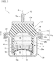
FIG. 1 is a longitudinal sectional view of a vibration damping device according to a first embodiment. -
FIG. 2 is a sectional view taken along line A-A of the vibration damping device ofFIG. 1 . -
FIG. 3 is a sectional view taken along line B-B of the vibration damping device ofFIG. 2 . -
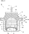
FIG. 4 is a longitudinal sectional view of a vibration damping device according to a second embodiment. -
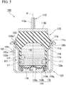
FIG. 5 is a longitudinal sectional view of a vibration damping device according to a third embodiment. - Hereinafter, a configuration of a vibration damping device according to a first embodiment will be described with reference to
FIG. 1 . - As shown in
FIG. 1 , avibration damping device 1 includes atubular metal bracket 20 which is connected to any one of a vibration generating portion and a vibration receiving portion, afirst attachment member 12 which is connected to the other thereof, a tubularsecond attachment member 11 which is inserted into themetal bracket 20, anelastic body 13 which connects thefirst attachment member 12 and thesecond attachment member 11 to each other, apartition member 17 which partitions aliquid chamber 14 in thesecond attachment member 11 in which a liquid is enclosed into amain liquid chamber 15 having theelastic body 13 as a portion of a partition wall and anauxiliary liquid chamber 16 in an axial direction along a center axis O of thesecond attachment member 11, and adiaphragm 19 which constitutes a portion of the partition wall of theauxiliary liquid chamber 16. Thesecond attachment member 11 is connected to any one of the vibration generating portion and the vibration receiving portion via themetal bracket 20. - For example, a case where the
vibration damping device 1 is used as an engine mount of an automobile, thesecond attachment member 11 is connected to a vehicle body serving as the vibration receiving portion via themetal bracket 20, and thefirst attachment member 12 is connected to an engine serving as the vibration generating portion. Accordingly, vibrations of the engine are prevented from being transmitted to the vehicle body. In the way, in a case where thevibration damping device 1 is connected to the engine, heat of the engine is transmitted to themetal bracket 20, and thus, the temperature of themetal bracket 20 increases. - Here, in the first embodiment, the
main liquid chamber 15 side along the axial direction with respect to thepartition member 17 is referred to as an upper side, and theauxiliary liquid chamber 16 side along the axial direction is referred to as a lower side. In addition, in a plan view when thevibration damping device 1 is viewed in the axial direction, a direction orthogonal to the center axis O is referred to as a radial direction, and a direction around the center axis O is referred to as a circumferential direction. - The
first attachment member 12 is formed in a rod shape, and includes anattachment shaft 12a which is provided coaxially with the center axis O and a disk-shaped connection plate 12b which extends radially outward from a lower end of theattachment shaft 12a. A male screw portion which connects thevibration damping device 1 to the vehicle body or the like is formed on an outer circumferential surface of theattachment shaft 12a. A lower surface of theconnection plate 12b is vulcanization-bonded to an upper end surface of theelastic body 13. - The
second attachment member 11 includes a main bodytubular portion 11a which is formed in a tubular shape coaxially with the center axis O and an inclinationtubular portion 11b which extends upward as going radially outward from an upper end opening edge of the main bodytubular portion 11a. A lower end opening portion of the main bodytubular portion 11a is caulked radially inward. An inner circumferential surface of the main bodytubular portion 11a is covered with a coating rubber. The coating rubber is formed integrally with theelastic body 13. - The
elastic body 13 is formed of a material having elasticity such as rubber. Theelastic body 13 gradually extends radially outward as going downward from a lower surface of theconnection plate 12b. An outer circumferential side of theelastic body 13 is vulcanization bonded to an inner circumferential surface of the inclinationtubular portion 11b of thesecond attachment member 11. An upper end opening portion of thesecond attachment member 11 is hermetically sealed by theelastic body 13. - A
tubular diaphragm ring 18 is liquid-tightly fitted into a lower end portion of thesecond attachment member 11 via a coating rubber. An outer circumferential portion of the disk-shaped diaphragm 19 which is formed of a rubber material or the like in an elastically deformable manner is vulcanization-bonded to an inner circumferential surface of thediaphragm ring 18. The lower end portion of thesecond attachment member 11 is caulked radially inward, and thus, thediaphragm ring 18 is fixed. The lower end opening portion of thesecond attachment member 11 is hermetically sealed by thediaphragm 19. - The
liquid chamber 14 in thesecond attachment member 11 in which the liquid is enclosed is defined by thediaphragm 19 and theelastic body 13. In addition, for example, water, ethylene glycol, or the like can be used as the liquid. - A lower
tubular portion 19a extending downward is formed on an outer circumferential edge portion of thediaphragm 19. The lowertubular portion 19a protrudes downward from thesecond attachment member 11. - The
partition member 17 is formed in a flat disk shape and is fitted into thesecond attachment member 11. Accordingly, theliquid chamber 14 in thesecond attachment member 11 is partitioned into themain liquid chamber 15 which is defined by theelastic body 13 and thepartition member 17 and theauxiliary liquid chamber 16 which is defined by thediaphragm 19 and thepartition member 17. In addition, thediaphragm 19 is deformed to be expanded or contracted according to an inflow of the liquid into theauxiliary liquid chamber 16 and an outflow of the liquid from theauxiliary liquid chamber 16. - A
restriction passage 21 which communicates with themain liquid chamber 15 and theauxiliary liquid chamber 16 is formed in thepartition member 17. Therestriction passage 21 communicates with themain liquid chamber 15 and theauxiliary liquid chamber 16 through a main liquid chamber-side opening (not shown) and an auxiliary liquid chamber-side opening (not shown) which are formed in thepartition member 17. - If axial vibrations are input to the
vibration damping device 1, thediaphragm 19 is deformed to be expanded or contracted, and the liquid flows between themain liquid chamber 15 and the auxiliaryliquid chamber 16 through therestriction passage 21. Accordingly, the vibrations are dampened and absorbed. - For example, aluminum or the like can be used as a material of the
metal bracket 20. - The
metal bracket 20 includes an accommodationtubular portion 20a which is formed in a tubular shape with a bottom coaxially with the center axis O and afixing portion 20b which is formed on an upper end portion of the accommodationtubular portion 20a. - The main body
tubular portion 11a of thesecond attachment member 11 is accommodated in the accommodationtubular portion 20a. That is, the lowertubular portion 19a of thediaphragm 19 is in airtight-contact with a bottom wall of the accommodationtubular portion 20a of themetal bracket 20. An air chamber S1 is defined by an upper surface in the bottom wall of theaccommodation tubular portion 20a, an inner circumferential surface of the lowertubular portion 19a, and a lower surface of thediaphragm 19. For example, air having an atmospheric pressure or the like is enclosed in the air chamber S1. - The fixing
portion 20b is formed in an annular shape which extends radially outward from an upper end opening edge of theaccommodation tubular portion 20a. A protrusion (hereinafter, referred to as arigid portion 20c) extending upward is formed on an outer circumferential edge of the fixingportion 20b. As shown inFIGS. 2 and 3 , a plurality ofrigid portions 20c are formed on an outer circumferential edge of the fixingportion 20b at intervals in the circumferential direction. - Here, in the
second attachment member 11 of the first embodiment, an annularupper flange 11 c which extends radially outward from an upper end portion of theinclination tubular portion 11b, an uppertubular portion 11e which extends downward from an outer circumferential edge portion of theupper flange 11c, and alower flange 11f which extends radially inward from a lower end opening edge of the uppertubular portion 11e. A fixedportion 11g includes theupper flange 11c, the uppertubular portion 11e, and thelower flange 11f. The fixingportion 20b and therigid portions 20c of themetal bracket 20 are axially interposed between theupper flange 11 c and thelower flange 11f, and thus, the fixedportion 11g is fixed to the fixingportion 20b. For example, thelower flange 11f can be formed by setting the fixingportion 20b and therigid portions 20c into the uppertubular portion 11e, and thereafter, radially inward deforming and caulking a portion of the uppertubular portion 11e downward protruding from the fixingportion 20b. - In addition, in the first embodiment, the
rigid portions 20c are formed integrally with themetal bracket 20. However, therigid portions 20c and themetal bracket 20 may be separated from each other. - An outer diameter of the main
body tubular portion 11a of thesecond attachment member 11 is smaller than an inner diameter of theaccommodation tubular portion 20a of themetal bracket 20. Accordingly, a gap S2 is formed between an outer circumferential surface of the mainbody tubular portion 11a and an inner circumferential surface of theaccommodation tubular portion 20a. The gap S2 is provided between a portion of the outer circumferential surface of thesecond attachment member 11 except for the fixedportion 11g, and a portion of the inner circumferential surface of themetal bracket 20 except for the fixingportion 20b, and continuously extends over the entire circumference. - Moreover, a
heat insulating member 22 which is an annular second seal portion is provided between theupper flange 11c of the fixedportion 11g and the fixingportion 20b in a compressed state. For example, a thermoplastic resin, a thermosetting resin, nylon, ceramic, or the like can be used as a material of theheat insulating member 22. Theheat insulating member 22 is provided between the fixedportion 11g and the fixingportion 20b in a compressed state, the fixedportion 11g is fixed to the fixingportion 20b, and thus, the gap S2 becomes a sealed space. - In addition, each of the
heat insulating member 22 and therigid portion 20c abuts against both theupper flange 11c of the fixedportion 11g and the fixingportion 20b. - Moreover, the gap S2 in the first embodiment is a vacuum sealed space. In addition, the lower
tubular portion 19a of thediaphragm 19 and the bottom wall in theaccommodation tubular portion 20a of themetal bracket 20 is in airtight-contact with each other, and thus, even when the gap S2 is the vacuum sealed space, air in the air chamber S1 can be prevented from leaking into the gap S2. - In a manufacturing method of the above-described
vibration damping device 1, for example, after each member is assembled in a vacuum chamber, air may be injected into the air chamber S1 from an air hole which is formed in the bottom wall of theaccommodation tubular portion 20a of themetal bracket 20 in advance. - Alternatively, after the
vibration damping device 1 is assembled at the atmospheric pressure, the air in the gap S2 is extracted from an air hole which is formed on a circumferential wall of theaccommodation tubular portion 20a in advance, and thus, the inside of the gap S2 may be evacuated. In this case, thevibration damping device 1 may be accommodated in a vacuum chamber in a state where the air hole is open and the air in the gap S2 may be extracted, or the air hole may be connected to a decompression device or the like such that the air in the gap S2 is extracted. - According to the
vibration damping device 1 configured as described above, the gap S2 continuously extending over the entire circumference is provided between the inner circumferential surface of themetal bracket 20 and the outer circumferential surface of thesecond attachment member 11, and theheat insulating member 22 is provided between the fixingportion 20b of themetal bracket 20 and the fixedportion 11g of thesecond attachment member 11. In this way, the gap S2 and theheat insulating member 22 are provided between themetal bracket 20 and thesecond attachment member 11, and thus, it is possible to prevent heat from being transmitted from themetal bracket 20 to thesecond attachment member 11. - In addition, the
rigid portion 20c having a higher hardness than that of theheat insulating member 22 is provided between the fixingportion 20b and the fixedportion 11g together with theheat insulating member 22, and thus, during assembly, theheat insulating member 22 is prevented from being interposed between the fixingportion 20b and the fixedportion 11g and being largely deformed to be contracted. Accordingly, temporal contraction deformation of theheat insulating member 22 during use of thevibration damping device 1 decreases, rattling of themetal bracket 20 and thesecond attachment member 11 is suppressed, the gap S2 between themetal bracket 20 and thesecond attachment member 11 is secured, and thus, it is possible to maintain the above-described insulating effects. - In addition, for example, compared to a case where the
rigid portion 20c is continuously provided on the entire circumference, the plurality ofrigid portions 20c are provided at intervals in the circumferential direction, it is possible to prevent heat from being transmitted from themetal bracket 20 to thesecond attachment member 11 via therigid portions 20c. - Moreover, the gap S2 is a vacuum sealed space, and thus, it is possible to more reliably prevent heat from being transmitted from the inner circumferential surface of the
metal bracket 20 to the outer circumferential surface of thesecond attachment member 11. - Next, a second embodiment according to the present invention will be described with reference to
FIG. 4 . However, a basic configuration of the second embodiment is similar to that of the first embodiment. Accordingly, the same reference numerals are assigned to similar configurations, descriptions thereof are omitted, and only different matters are described. - As shown in
FIG. 4 , avibration damping device 10 of the second embodiment has asecond attachment member 23 instead of thesecond attachment member 11 of the first embodiment. - The
second attachment member 23 is formed of a material having a smaller thermal conductivity than that of metal and large heat insulating properties. Thesecond attachment member 23 includes a mainbody tubular portion 23a, aninclination tubular portion 23b which extends radially outward as going upward from an upper end opening edge of the mainbody tubular portion 23a, an annular fixedportion 23c which extends radially outward from an upper end opening edge of theinclination tubular portion 23b, and a fixedtubular portion 23d which extends downward from an outer circumferential edged of the fixedportion 23c. A plurality ofrigid portions 23e are provided on the fixedtubular portion 23d at intervals in the circumferential direction. Therigid portions 23e are formed of metal, and can be provided on the fixedtubular portion 23d by insert molding or the like, for example. - Moreover, the
metal bracket 20 of the second embodiment includes an annular lower-side flange portion 20f which extends radially outward from the upper end opening edge of theaccommodation tubular portion 20a, an upper-side tubular portion 20g which extends upward from an outer circumferential edge of the lower-side flange portion 20f, and an annular upper-side flange portion 20d which extends radially inward from an upper end opening edge of the upper-side tubular portion 20g. The fixingportion 20b of the second embodiment includes the lower-side flange portion 20f, the upper-side tubular portion 20g, and the upper-side flange portion 20d. - The fixed
portion 23c and the fixedtubular portion 23d are interposed between the lower-side flange portion 20f and the upper-side flange portion 20d of themetal bracket 20 in the axial direction. Accordingly, the fixedportion 23c and the fixedtubular portion 23d are fixed to the fixingportion 20b. - According to the
vibration damping device 10 of the second embodiment, thesecond attachment member 23 is formed of a material having larger thermal conductivity than that of metal, it is possible to more reliably prevent heat from themetal bracket 20 from being transmitted to theelastic body 13 positioned in thesecond attachment member 23 and the liquid in theliquid chamber 14. - Accordingly, it is possible more reliably prevent temperatures of an adhesion portion between the
elastic body 13 and thesecond attachment member 23 from increasing, and the adhesion portion from deteriorating, the temperature of the liquid in theliquid chamber 14 from increasing, and occurrence of cavitation. - Hereinafter, a configuration of a vibration damping device according to a third embodiment will be described with reference to
FIG. 5 . - As shown in
FIG. 5 , avibration damping device 100 includes atubular metal bracket 120 which is connected to any one of the vibration generating portion and the vibration receiving portion, afirst attachment member 112 which is connected to the other thereof, a tubularsecond attachment member 111 which is inserted into themetal bracket 120, anelastic body 113 which connects thefirst attachment member 112 and thesecond attachment member 111 to each other, apartition member 117 which partitions aliquid chamber 114 in thesecond attachment member 111 in which a liquid is enclosed into a mainliquid chamber 115 having theelastic body 113 as a portion of a partition wall and an auxiliaryliquid chamber 116 in an axial direction along a center axis O of thesecond attachment member 111, and adiaphragm 119 which constitutes a portion of the partition wall of the auxiliaryliquid chamber 116. Thesecond attachment member 111 is connected to any one of the vibration generating portion and the vibration receiving portion via themetal bracket 120. - For example, a case where the
vibration damping device 100 is used as an engine mount of an automobile, thesecond attachment member 111 is connected to a vehicle body serving as the vibration receiving portion via themetal bracket 120, and thefirst attachment member 112 is connected to an engine serving as the vibration generating portion. Accordingly, vibrations of the engine are prevented from being transmitted to the vehicle body. In the way, in a case where thevibration damping device 1 is connected to the engine, heat of the engine is transmitted to themetal bracket 120, and thus, the temperature of themetal bracket 120 increases. - Here, in the third embodiment, the main
liquid chamber 115 side along the axial direction with respect to thepartition member 117 is referred to as an upper side, and the auxiliaryliquid chamber 116 side along the axial direction is referred to as a lower side. In addition, in a plan view when thevibration damping device 100 is viewed in the axial direction, a direction orthogonal to the center axis O is referred to as a radial direction, and a direction around the center axis O is referred to as a circumferential direction. - The
first attachment member 112 is formed in a rod shape, and includes anattachment shaft 112a which is provided coaxially with the center axis O and a disk-shapedconnection plate 112b which extends radially outward from a lower end of theattachment shaft 112a. A male screw portion which connects thevibration damping device 100 to the vehicle body or the like is formed on an outer circumferential surface of theattachment shaft 112a. A lower surface of theconnection plate 112b is vulcanization-bonded to an upper end surface of theelastic body 113. - The
second attachment member 111 includes a mainbody tubular portion 111a which is formed in a tubular shape coaxially with the center axis O, aninclination tubular portion 111b which extends upward as going radially outward from an upper end opening edge of the mainbody tubular portion 111 a, anupper tubular portion 111d which extends upward from an upper end portion of theinclination tubular portion 111b, and an annular upper-side flange portion 111c which protrudes radially outward from an upper end opening edge of theupper tubular portion 111d and is a fixed portion. - A lower end opening portion of the main
body tubular portion 111a is caulked radially inward. An inner circumferential surface of the mainbody tubular portion 111 a is covered with a coating rubber. The coating rubber is formed integrally with theelastic body 113. Theupper tubular portion 111d is fitted into themetal bracket 120. In the third embodiment, theupper tubular portion 111d is press-fitted into an upper end opening portion of themetal bracket 120, and thus, thesecond attachment member 111 is fixed to themetal bracket 120. In addition, for example, thesecond attachment member 111 may be fixed to themetal bracket 120 using caulking processing or the like. - In both end opening portions of the
second attachment member 111 in the axial direction, one is closed by theelastic body 113 and the other is closed body is closed by thediaphragm 119. InFIG. 5 , an upper end opening portion of thesecond attachment member 111 is closed by theelastic body 113, and a lower end opening portion thereof is closed by thediaphragm 119. - The
elastic body 113 is formed of a material having elasticity such as rubber. Theelastic body 113 gradually extends radially outward as going downward from a lower surface of theconnection plate 112b. An outer circumferential side of theelastic body 113 is vulcanization bonded to a portion of an upper surface of the upper-side flange portion 111c of thesecond attachment member 111 and inner circumferential surfaces of theupper tubular portion 111d and theinclination tubular portion 111b of thesecond attachment member 111. - The
liquid chamber 114 in thesecond attachment member 111 in which the liquid is enclosed is defined by theelastic body 113, thediaphragm 119, and the coating rubber. In addition, for example, water, ethylene glycol, or the like can be used as the liquid. - The
partition member 117 is formed in a flat disk shape and is fitted into thesecond attachment member 111. Accordingly, theliquid chamber 114 in thesecond attachment member 111 is partitioned into the mainliquid chamber 115 which is defined by theelastic body 113 and thepartition member 117 and the auxiliaryliquid chamber 116 which is defined by thediaphragm 119 and thepartition member 117. In addition, the diaphragmmain body 119a is deformed to be expanded or contracted according to an inflow of the liquid into the auxiliaryliquid chamber 116 and an outflow of the liquid from the auxiliaryliquid chamber 116. - A
restriction passage 121 which communicates with the mainliquid chamber 115 and the auxiliaryliquid chamber 116 is formed in thepartition member 117. Therestriction passage 121 communicates with the mainliquid chamber 115 and the auxiliaryliquid chamber 116 through a main liquid chamber-side opening (not shown) and an auxiliary liquid chamber-side opening (not shown) which are formed in thepartition member 117. - If axial vibrations are input to the
vibration damping device 100, the diaphragmmain body 119a is deformed to be expanded or contracted, and the liquid flows between the mainliquid chamber 115 and the auxiliaryliquid chamber 116 through therestriction passage 121. Accordingly, the vibrations are dampened and absorbed. - For example, aluminum or the like can be used as a material of the
metal bracket 120. - The
metal bracket 120 includes anaccommodation tubular portion 120a which is formed in a tubular shape with a bottom coaxially with the center axis O and a lower-side flange portion 120b which protrudes radially outward from an upper end opening edge of theaccommodation tubular portion 120a and is the fixing portion. - The main
body tubular portion 111a, theinclination tubular portion 111b, and theupper tubular portion 111d of thesecond attachment member 111 are accommodated in theaccommodation tubular portion 120a. The lower-side flange portion 120b abuts against or approaches the upper-side flange portion 111c of thesecond attachment member 111 from below. - Here, a chamfered
portion 120d which extends radially outward as going upward is formed on the upper end opening edge of themetal bracket 120 of the third embodiment. An O ring (hereinafter, referred to a second seal portion 123) formed of rubber or the like is interposed between the chamferedportion 120d, and the upper-side flange portion 111c and theupper tubular portion 111d of the second attachment member. Accordingly, thesecond seal portion 123 is elastically deformed in an approximately triangular shape, and an upper-side (one side in the axial direction) end portion of thesecond attachment member 111 is airtightly fitted into themetal bracket 120 via thesecond seal portion 123. - In addition, in the third embodiment, the O ring is used as the
second seal portion 123. However, for example, thesecond seal portion 123 may be formed by vulcanization-bonding to rubber or the like to themetal bracket 120 or thesecond attachment member 111. - The
diaphragm 119 includes atubular diaphragm ring 118 which is liquid-tightly fitted into a lower end portion (the other end portion in the axial direction) of thesecond attachment member 111 via a coating rubber, and an elastically deformable disk-shaped diaphragmmain body 119a which closes the inside of thediaphragm ring 118. - The diaphragm
main body 119a is formed of rubber or the like and is vulcanization-bonded to an inner circumferential surface of thediaphragm ring 118. A lower end portion of thesecond attachment member 111 is caulked radially inward, and thus, thediaphragm ring 118 is fixed. - The
diaphragm ring 118 includes a tubular ringmain body portion 118a and an annularpressure receiving portion 118b which extends radially inward from the lower end opening edge of the ringmain body portion 118a. In addition, in thediaphragm ring 118, afirst seal portion 119b continuously extending over the entire circumference is provided downward. - For example, each of the ring
main body portion 118a and thepressure receiving portion 118b is formed of a material having a large hardness such as metal. For example, thefirst seal portion 119b is formed of a material having large elasticity such as rubber. At least a portion of thefirst seal portion 119b is axially interposed between thepressure receiving portion 118b and a bottom wall portion of themetal bracket 120. In addition, in the third embodiment, thefirst seal portion 119b is integrally formed with the diaphragmmain body 119a. However, thefirst seal portion 119b and the diaphragmmain body 119a may be separated from each other. In this case, for example, an O ring or the like may be used as thefirst seal portion 119b. - An air chamber S11 is defined by an upper surface in the bottom wall portion of the
accommodation tubular portion 120a, an inner circumferential surface of thefirst seal portion 119b, and an upper surface of the diaphragmmain boy 119a. A lower end portion of thefirst seal portion 119b airtightly abuts against an inner surface of the bottom wall portion of themetal bracket 120. Accordingly, the air chamber S11 is sealed. - For example, air having an atmospheric pressure or the like is enclosed in the air chamber S11. Therefore, an outer surface of the diaphragm
main body 119a is exposed to the atmospheric pressure. - An outer diameter of the main
body tubular portion 111a of thesecond attachment member 111 is smaller than an inner diameter of theaccommodation tubular portion 120a of themetal bracket 120, and thus, a gap is formed between thesecond attachment member 111 and themetal bracket 120. In addition, a lower end portion of the gap is closed by thefirst seal portion 119b, an upper end portion thereof is closed by thesecond seal portion 123, and the gap is in a vacuum state. According to this configuration, between an outer circumferential surface of thesecond attachment member 111 and an inner circumferential surface of themetal bracket 120, a portion positioned between thefirst seal portion 119b and thesecond seal portion 123 becomes a vacuum sealed space S21 which continuously extends over the entire circumference. - In addition, the
first seal portion 119b of thediaphragm 119 and the bottom wall portion in theaccommodation tubular portion 120a of themetal bracket 120 is in airtight-contact with each other, and thus, even when the sealed space S21 is in a vacuum state, air in the air chamber S11 can be prevented from leaking into the gap S21. - In a manufacturing method of the above-described
vibration damping device 100, for example, in a state where the liquid is enclosed in theliquid chamber 114, thefirst attachment member 112, theelastic body 113, thepartition member 117, thesecond attachment member 111, and thediaphragm 119 are assembled, and thus, an intermediate unit is achieved. - In addition, after the intermediate unit is press-fitted into the
metal bracket 120 by a press machine or the like in a vacuum chamber, air may be injected into the air chamber S11 from an air hole (not shown) which is formed in a bottom wall portion of theaccommodation tubular portion 120a of themetal bracket 120 in advance. - Alternatively, the intermediate unit is press-fitted into the
metal bracket 120 at the atmospheric pressure, the air in the sealed space S21 is extracted from anexhaust hole 120c which is formed on a circumferential wall of theaccommodation tubular portion 120a in advance, and thus, the inside of the sealed space S21 may be evacuated. In this case, thevibration damping device 100 may be accommodated in a vacuum chamber in a state where theexhaust hole 120c is open and the air in the sealed space S21 may be extracted, or theexhaust hole 120c may be connected to a decompression device or the like such that the air in the sealed space S21 is extracted. After the air in the sealed space S21 is extracted, ashaft portion 122b of arivet 122 is inserted into theexhaust hole 120c, ahead portion 122a of therivet 122 comes into contact with the outer circumferential surface of theaccommodation tubular portion 120a, and thus, theexhaust hole 120c is closed, and the vacuum state in the sealed space S21 can be maintained. - According to the
vibration damping device 100 configured as described above, in the portion between the outer circumferential surface of thesecond attachment member 111 and the inner circumferential surface of themetal bracket 120, the portion positioned between thefirst seal portion 119b and thesecond seal portion 123 becomes the vacuum sealed space S21 which continuously extends over the entire circumference, and thus, it is possible to prevent heat from being transmitted from themetal bracket 120 to thesecond attachment member 111. - In addition, the outer surface of the diaphragm
main body portion 119a is exposed to the atmospheric pressure, the diaphragmmain body 119a is deformed by the inflow and the outflow of the liquid with respect to the auxiliaryliquid chamber 116 generated by vibrations input to thevibration damping device 100, and thus, a function for absorbing and dampening the vibrations can be exerted. In addition, thefirst seal portion 119b is not provided in the diaphragmmain body 119a and is provided to protrude from thediaphragm ring 118 having a large hardness, and thus, thefirst seal portion 119b can strongly abut against themetal bracket 120. Accordingly, it is possible to prevent the air in the air chamber S11 coming into contact with the diaphragmmain body 119a from entering the sealed space S21, the vacuum state of the sealed space S21 can be maintained, and thus, it is possible to reliably realize the above-described insulating effects. - In addition, the air chamber S11 is defined by the inner surface of the bottom wall portion of the
metal bracket 120 which is formed in a tubular shape with a bottom, the outer surface of the diaphragmmain body 119a, and thefirst seal portion 119b which extends over the entire circumference of thediaphragm ring 118, and the air in the air chamber S11 is in contact with the outer surface of the diaphragmmain body 119a. In this way, the air in the air chamber S11 which is hermetically sealed is in contact with the outer surface of the diaphragmmain body 119a, and thus, for example, a pressure in the air chamber S11 is larger than the atmospheric pressure, it is possible to suppress occurrence of cavitation. Moreover, for example, compared to a case where the air chamber S11 is not hermetically sealed, heated air around thevibration damping device 100 is prevented from entering the inside of thevibration damping device 100, and it is possible to increase the insulating effects. - Accordingly, compared to a case where the diaphragm
main body 119a is exposed to the air outside thevibration damping device 100, it is possible to stabilize components or the like of the air being in contact with the outer surface of the diaphragmmain body 119a, and it is possible to prevent deterioration or the like of the diaphragmmain body 119a. - Moreover, for example, it is possible to adjust ease of a deformation of the diaphragm
main body 119a by adjusting an internal volume of the air chamber S11, and for example, compared to a case where a material of thediaphragm 119 is changed, it is possible to easily tune characteristics of thevibration damping device 100 with respect to the input vibrations. - In addition, at least a portion of the
first seal portion 119b is interposed between thepressure receiving portion 118b and themetal bracket 120 in the axial direction, and thus, when thefirst seal portion 119b is compressed in the axial direction, thepressure receiving portion 118b can receive the pressure. Accordingly, for example, it is possible to prevent thefirst seal portion 119b from being deformed or displaced together with the diaphragmmain body 119a, and to maintain a vacuum state of the sealed space S21. - Moreover, a technical scope of the present invention is not limited to the above-described embodiments, and various modifications can be made within a range which does not depart from the scope of the present invention.
- For example, in the above-described embodiments, the gap S2 is a vacuum sealed space. However, a gas such as air, a liquid or solid heat insulating material, or the like may be enclosed in the gap S2.
- In addition, in the example of
FIG. 2 , theheat insulating member 22 may be provided between the plurality ofrigid portions 20c in the circumferential direction. - In addition, shapes of the fixed
portion 11g of thesecond attachment member 11 and the fixingportion 20b of themetal bracket 20 are not limited to the above-described embodiments, and various shapes can be applied. - For example, in the first embodiment, even in a case where the fixed
portion 11g and the fixingportion 20b having shapes different from the shapes shown inFIG. 1 are provided, therigid portions 20c and theheat insulating member 22 are provided between the fixedportion 11g and the fixingportion 20b, and thus, it is possible to exert effects of the present invention. - For example, in the third embodiment, the air chamber S11 is closed by the bottom wall portion of the
accommodation tubular portion 120a, thefirst seal portion 119b, and the diaphragmmain body 119a. However, the present invention is not limited to this. For example, a through-hole may be formed on the bottom wall portion of theaccommodation tubular portion 120a, the inside of the air chamber S11 and an external space of thevibration damping device 100 may communicate with each other via the through-hole, and the diaphragmmain body 119a is exposed to the atmospheric pressure. - Moreover, in the third embodiment, the
first seal portion 119b abuts against the bottom wall portion of themetal bracket 120. However, thefirst seal portion 119b may abut against a circumferential wall of themetal bracket 120. - Moreover, in the third embodiment, the sealed space S21 is in a vacuum state. However, a gas such as air, a liquid or solid heat insulating material, or the like may be enclosed in the sealed space S21.
- Moreover, the gas enclosed in the air chamber S11 is not limited to the air having the atmospheric pressure, and may be a gas having a higher pressure than the pressure in the sealed space S21. The outer surface of the diaphragm
main body 119a is exposed to the gas having a higher pressure than the pressure in the sealed space S21. Accordingly, for example, it is possible to easily tune the characteristics of thevibration damping device 100 by adjusting the pressure of the gas. - Moreover, shapes of the
first seal portion 119b and the bottom portion of themetal bracket 120 are not limited to the example ofFIG. 5 . For example, a convex portion protruding upward may be formed on the bottom portion of themetal bracket 120, and the convex portion may abut against thefirst seal portion 119b to improve sealing performance. Alternatively, themetal bracket 120 having a convex portion or a concave portion abutting against thefirst seal portion 119b from a radially inner side or a radially outer side may be adopted, and sealing performance when thefirst seal portion 119 b is deformed at the time of the vibration input may be secured. - In addition, the
vibration damping devices - Moreover, within a scope of the present invention, it is possible to appropriately replace constituent elements in the above-described embodiments with well-known constituent elements, and the above-described embodiment and modification examples may be appropriately combined.
- According to the vibration damping devices of the present invention, it is possible to prevent heat from being transmitted to the attachment member provided in the bracket.
-
- 1, 10, 100:
- vibration damping device
- 11, 23, 111:
- second attachment member
- 11g, 23c:
- fixed portion
- 12, 112:
- first attachment member
- 14, 114:
- liquid chamber
- 15, 115:
- main liquid chamber
- 16, 116:
- auxiliary liquid chamber
- 17, 117:
- partition member
- 18, 118:
- diaphragm ring
- 19, 119:
- diaphragm
- 20, 120:
- metal bracket
- 20b:
- fixing portion
- 20c, 23e:
- rigid portion
- 22:
- heat insulating member (second seal portion)
- 111c:
- upper-side flange portion (fixed portion)
- 119a:
- diaphragm main body
- 119b:
- first seal portion
- 120b:
- lower-side flange portion (fixing portion)
- 123:
- second seal portion
- S1, S11:
- air chamber
- S2:
- gap
- S21:
- sealed space
Claims (6)
- A vibration damping device comprising:a tubular metal bracket which is connected to any one of a vibration generating portion and a vibration receiving portion;a first attachment member which is connected to the other of the vibration generating portion and the vibration receiving portion;a tubular second attachment member which is inserted into the metal bracket;an elastic body which connects the first attachment member and the second attachment member to each other;a partition member which partitions a liquid chamber in the second attachment member into a main liquid chamber having the elastic body as a portion of a partition wall and an auxiliary liquid chamber; anda diaphragm which constitutes a portion of a partition wall of the auxiliary liquid chamber,wherein one of both end opening portions of the second attachment member in an axial direction is closed by the elastic body and the other thereof is closed by the diaphragm,wherein a fixing portion which fixes the second attachment member is formed on the metal bracket,wherein a fixed portion which is fixed to the fixing portion of the metal bracket is formed on the second attachment member,wherein a gap is provided between a portion of an outer circumferential surface of the second attachment member except for the fixed portion, and a portion of an inner circumferential surface of the metal bracket except for the fixing portion, andwherein a second seal portion is provided between the fixed portion and the fixing portion.
- The vibration damping device according to claim 1,
wherein a rigid portion having a higher hardness than that of a heat insulating member which is the second seal portion is further provided between the fixed portion and the fixing portion, and
wherein a plurality of the rigid portions are provided at intervals in a circumferential direction. - The vibration damping device according to claim 1 or 2,
wherein the gap is a vacuum sealed space. - The vibration damping device according to claim 1,
wherein the diaphragm includes a diaphragm ring which is fitted into the other end portion of the second attachment member in the axial direction and an elastically deformable diaphragm main body which closes an inside of the diaphragm ring,
wherein a first seal portion which continuously extends over the entire circumference of the diaphragm ring and abuts against the metal bracket protrudes from the diaphragm ring,
wherein the one end portion of the second attachment member in the axial direction is fitted into the metal bracket via the second seal portion, and
wherein between the outer circumferential surface of the second attachment member and the inner circumferential surface of the metal bracket, a portion positioned between the first seal portion and the second seal portion is a vacuum sealed space. - The vibration damping device according to claim 4,
wherein the metal bracket is formed in a tubular shape with a bottom and the first seal portion abuts against an inner surface of the metal bracket. - The vibration damping device according to claim 4 or 5,
wherein an outer surface of the diaphragm main body is exposed to a gas having a higher pressure than a pressure in the sealed space.
Applications Claiming Priority (3)
| Application Number | Priority Date | Filing Date | Title |
|---|---|---|---|
| JP2016187797A JP6707430B2 (en) | 2016-09-27 | 2016-09-27 | Anti-vibration device |
| JP2016187796A JP6761318B2 (en) | 2016-09-27 | 2016-09-27 | Anti-vibration device |
| PCT/JP2017/034714 WO2018062165A1 (en) | 2016-09-27 | 2017-09-26 | Vibration damping device |
Publications (3)
| Publication Number | Publication Date |
|---|---|
| EP3521655A1 true EP3521655A1 (en) | 2019-08-07 |
| EP3521655A4 EP3521655A4 (en) | 2019-10-23 |
| EP3521655B1 EP3521655B1 (en) | 2020-09-02 |
Family
ID=61760395
Family Applications (1)
| Application Number | Title | Priority Date | Filing Date |
|---|---|---|---|
| EP17856115.5A Active EP3521655B1 (en) | 2016-09-27 | 2017-09-26 | Vibration damping device |
Country Status (4)
| Country | Link |
|---|---|
| US (1) | US10851866B2 (en) |
| EP (1) | EP3521655B1 (en) |
| CN (1) | CN109790901A (en) |
| WO (1) | WO2018062165A1 (en) |
Cited By (1)
| Publication number | Priority date | Publication date | Assignee | Title |
|---|---|---|---|---|
| EP4227553A4 (en) * | 2020-10-08 | 2024-10-16 | Prospira Corporation | Vibration-damping device |
Families Citing this family (1)
| Publication number | Priority date | Publication date | Assignee | Title |
|---|---|---|---|---|
| CN116518009A (en) * | 2023-04-26 | 2023-08-01 | 芜湖安博帝特工业有限公司 | Engine hydraulic suspension |
Family Cites Families (23)
| Publication number | Priority date | Publication date | Assignee | Title |
|---|---|---|---|---|
| US20060064069A1 (en) * | 2000-04-12 | 2006-03-23 | Rajala Gregory J | Disposable undergarment and related manufacturing equipment and processes |
| JP4054079B2 (en) * | 1996-09-10 | 2008-02-27 | 株式会社ブリヂストン | Vibration isolator |
| JP4137201B2 (en) * | 1997-10-08 | 2008-08-20 | 株式会社ブリヂストン | Vibration isolator |
| JP4229294B2 (en) * | 1998-06-15 | 2009-02-25 | 富士重工業株式会社 | Engine mount structure |
| JP4003131B2 (en) * | 2003-01-31 | 2007-11-07 | 東海ゴム工業株式会社 | Fluid filled vibration isolator |
| JP4081421B2 (en) * | 2003-09-30 | 2008-04-23 | 東海ゴム工業株式会社 | Anti-vibration mount assembly |
| JP2006064033A (en) * | 2004-08-25 | 2006-03-09 | Tokai Rubber Ind Ltd | Fluid filled vibration isolator |
| JP2006064069A (en) * | 2004-08-26 | 2006-03-09 | Bridgestone Corp | Vibration control device |
| JP3989482B2 (en) * | 2004-11-04 | 2007-10-10 | 本田技研工業株式会社 | Vibration isolator |
| JP4842078B2 (en) * | 2006-01-31 | 2011-12-21 | 東海ゴム工業株式会社 | Fluid-filled vibration isolator and manufacturing method thereof |
| JP5000282B2 (en) | 2006-12-05 | 2012-08-15 | 山下ゴム株式会社 | Liquid seal vibration isolator |
| DE102007058191B4 (en) * | 2006-12-05 | 2016-04-07 | Honda Motor Co., Ltd. | Liquid enclosing vibration isolation device |
| JP5118904B2 (en) * | 2007-07-04 | 2013-01-16 | 東海ゴム工業株式会社 | Pneumatic actuator for vibration isolator and fluid filled vibration isolator using the same |
| JP5085502B2 (en) * | 2008-10-14 | 2012-11-28 | 東海ゴム工業株式会社 | Plastic cylindrical bracket and anti-vibration mount assembly using such plastic cylindrical bracket |
| JP5191950B2 (en) | 2009-05-19 | 2013-05-08 | 東洋ゴム工業株式会社 | Vibration isolator |
| US8960654B2 (en) * | 2009-07-28 | 2015-02-24 | Bridgestone Corporation | Vibration isolation device |
| DE102009043557B4 (en) | 2009-09-30 | 2017-10-19 | Vibracoustic Gmbh | Assembly storage and a storage core for it |
| JP5427616B2 (en) | 2010-01-12 | 2014-02-26 | 株式会社ブリヂストン | Vibration isolator |
| EP2525116B1 (en) | 2010-01-12 | 2017-11-15 | Bridgestone Corporation | Antivibration device |
| JP2012057780A (en) | 2010-09-13 | 2012-03-22 | Bridgestone Corp | Vibration control device |
| WO2012043483A1 (en) * | 2010-09-27 | 2012-04-05 | 株式会社ブリヂストン | Vibration damping device |
| KR101510350B1 (en) * | 2013-08-28 | 2015-04-07 | 현대자동차 주식회사 | Mounting device absorbing vibration |
| JP5899296B1 (en) * | 2014-11-26 | 2016-04-06 | 住友理工株式会社 | Vibration-proof electromagnetic actuator, and active fluid-filled vibration-proof device and active vibration-damping device using the same |
-
2017
- 2017-09-26 WO PCT/JP2017/034714 patent/WO2018062165A1/en not_active Ceased
- 2017-09-26 EP EP17856115.5A patent/EP3521655B1/en active Active
- 2017-09-26 US US16/335,548 patent/US10851866B2/en active Active
- 2017-09-26 CN CN201780058324.2A patent/CN109790901A/en active Pending
Cited By (2)
| Publication number | Priority date | Publication date | Assignee | Title |
|---|---|---|---|---|
| EP4227553A4 (en) * | 2020-10-08 | 2024-10-16 | Prospira Corporation | Vibration-damping device |
| US12523273B2 (en) | 2020-10-08 | 2026-01-13 | Prospira Corporation | Anti-vibration device |
Also Published As
| Publication number | Publication date |
|---|---|
| CN109790901A (en) | 2019-05-21 |
| US20190346009A1 (en) | 2019-11-14 |
| EP3521655B1 (en) | 2020-09-02 |
| WO2018062165A1 (en) | 2018-04-05 |
| US10851866B2 (en) | 2020-12-01 |
| EP3521655A4 (en) | 2019-10-23 |
Similar Documents
| Publication | Publication Date | Title |
|---|---|---|
| JP3629485B2 (en) | Liquid-filled vibration isolator | |
| US20200049224A1 (en) | Vibration-damping device | |
| EP3521655B1 (en) | Vibration damping device | |
| EP2620669B1 (en) | Anti-vibration device | |
| JP6761318B2 (en) | Anti-vibration device | |
| CN102414472B (en) | Vibration isolation device | |
| CN107532675B (en) | Isolation mounting | |
| US11167632B2 (en) | Vibration-damping device | |
| CN110030323B (en) | Vibration-proof device | |
| CN114402148A (en) | Vibration isolation device | |
| JP6707430B2 (en) | Anti-vibration device | |
| JP7854903B2 (en) | Vibration isolation device | |
| JPH0979311A (en) | Vibration insulating device | |
| JP2003083391A (en) | Liquid-filled vibration isolator | |
| KR102347074B1 (en) | Structure of engine-mount | |
| JP2010032023A (en) | Fluid-filled vibration isolation device | |
| JP5959346B2 (en) | Vibration isolator | |
| JP2020051458A (en) | Cylinder device and method of manufacturing the same | |
| CN117662669A (en) | Anti-vibration device and method of manufacturing the anti-vibration device | |
| JP4976080B2 (en) | Vibration isolator | |
| JPH06288423A (en) | Fluid-filled mounting device | |
| JP2003222182A (en) | Fluid filled type vibration damping device and method of manufacturing fluid filled type vibration damping device | |
| JP2014139457A (en) | Vibration isolator | |
| JP2005291279A (en) | Fluid filled vibration isolator | |
| JPH09257089A (en) | Vibration control device |
Legal Events
| Date | Code | Title | Description |
|---|---|---|---|
| STAA | Information on the status of an ep patent application or granted ep patent |
Free format text: STATUS: THE INTERNATIONAL PUBLICATION HAS BEEN MADE |
|
| PUAI | Public reference made under article 153(3) epc to a published international application that has entered the european phase |
Free format text: ORIGINAL CODE: 0009012 |
|
| STAA | Information on the status of an ep patent application or granted ep patent |
Free format text: STATUS: REQUEST FOR EXAMINATION WAS MADE |
|
| 17P | Request for examination filed |
Effective date: 20190322 |
|
| AK | Designated contracting states |
Kind code of ref document: A1 Designated state(s): AL AT BE BG CH CY CZ DE DK EE ES FI FR GB GR HR HU IE IS IT LI LT LU LV MC MK MT NL NO PL PT RO RS SE SI SK SM TR |
|
| AX | Request for extension of the european patent |
Extension state: BA ME |
|
| A4 | Supplementary search report drawn up and despatched |
Effective date: 20190924 |
|
| RIC1 | Information provided on ipc code assigned before grant |
Ipc: F16F 13/10 20060101AFI20190918BHEP |
|
| DAV | Request for validation of the european patent (deleted) | ||
| DAX | Request for extension of the european patent (deleted) | ||
| GRAP | Despatch of communication of intention to grant a patent |
Free format text: ORIGINAL CODE: EPIDOSNIGR1 |
|
| STAA | Information on the status of an ep patent application or granted ep patent |
Free format text: STATUS: GRANT OF PATENT IS INTENDED |
|
| INTG | Intention to grant announced |
Effective date: 20200428 |
|
| GRAS | Grant fee paid |
Free format text: ORIGINAL CODE: EPIDOSNIGR3 |
|
| GRAA | (expected) grant |
Free format text: ORIGINAL CODE: 0009210 |
|
| STAA | Information on the status of an ep patent application or granted ep patent |
Free format text: STATUS: THE PATENT HAS BEEN GRANTED |
|
| AK | Designated contracting states |
Kind code of ref document: B1 Designated state(s): AL AT BE BG CH CY CZ DE DK EE ES FI FR GB GR HR HU IE IS IT LI LT LU LV MC MK MT NL NO PL PT RO RS SE SI SK SM TR |
|
| REG | Reference to a national code |
Ref country code: GB Ref legal event code: FG4D |
|
| REG | Reference to a national code |
Ref country code: AT Ref legal event code: REF Ref document number: 1309174 Country of ref document: AT Kind code of ref document: T Effective date: 20200915 Ref country code: CH Ref legal event code: EP |
|
| REG | Reference to a national code |
Ref country code: DE Ref legal event code: R096 Ref document number: 602017023052 Country of ref document: DE |
|
| REG | Reference to a national code |
Ref country code: IE Ref legal event code: FG4D |
|
| REG | Reference to a national code |
Ref country code: LT Ref legal event code: MG4D |
|
| PG25 | Lapsed in a contracting state [announced via postgrant information from national office to epo] |
Ref country code: SE Free format text: LAPSE BECAUSE OF FAILURE TO SUBMIT A TRANSLATION OF THE DESCRIPTION OR TO PAY THE FEE WITHIN THE PRESCRIBED TIME-LIMIT Effective date: 20200902 Ref country code: BG Free format text: LAPSE BECAUSE OF FAILURE TO SUBMIT A TRANSLATION OF THE DESCRIPTION OR TO PAY THE FEE WITHIN THE PRESCRIBED TIME-LIMIT Effective date: 20201202 Ref country code: NO Free format text: LAPSE BECAUSE OF FAILURE TO SUBMIT A TRANSLATION OF THE DESCRIPTION OR TO PAY THE FEE WITHIN THE PRESCRIBED TIME-LIMIT Effective date: 20201202 Ref country code: GR Free format text: LAPSE BECAUSE OF FAILURE TO SUBMIT A TRANSLATION OF THE DESCRIPTION OR TO PAY THE FEE WITHIN THE PRESCRIBED TIME-LIMIT Effective date: 20201203 Ref country code: LT Free format text: LAPSE BECAUSE OF FAILURE TO SUBMIT A TRANSLATION OF THE DESCRIPTION OR TO PAY THE FEE WITHIN THE PRESCRIBED TIME-LIMIT Effective date: 20200902 Ref country code: FI Free format text: LAPSE BECAUSE OF FAILURE TO SUBMIT A TRANSLATION OF THE DESCRIPTION OR TO PAY THE FEE WITHIN THE PRESCRIBED TIME-LIMIT Effective date: 20200902 Ref country code: HR Free format text: LAPSE BECAUSE OF FAILURE TO SUBMIT A TRANSLATION OF THE DESCRIPTION OR TO PAY THE FEE WITHIN THE PRESCRIBED TIME-LIMIT Effective date: 20200902 |
|
| REG | Reference to a national code |
Ref country code: NL Ref legal event code: MP Effective date: 20200902 |
|
| REG | Reference to a national code |
Ref country code: AT Ref legal event code: MK05 Ref document number: 1309174 Country of ref document: AT Kind code of ref document: T Effective date: 20200902 |
|
| PG25 | Lapsed in a contracting state [announced via postgrant information from national office to epo] |
Ref country code: RS Free format text: LAPSE BECAUSE OF FAILURE TO SUBMIT A TRANSLATION OF THE DESCRIPTION OR TO PAY THE FEE WITHIN THE PRESCRIBED TIME-LIMIT Effective date: 20200902 Ref country code: PL Free format text: LAPSE BECAUSE OF FAILURE TO SUBMIT A TRANSLATION OF THE DESCRIPTION OR TO PAY THE FEE WITHIN THE PRESCRIBED TIME-LIMIT Effective date: 20200902 Ref country code: LV Free format text: LAPSE BECAUSE OF FAILURE TO SUBMIT A TRANSLATION OF THE DESCRIPTION OR TO PAY THE FEE WITHIN THE PRESCRIBED TIME-LIMIT Effective date: 20200902 |
|
| PG25 | Lapsed in a contracting state [announced via postgrant information from national office to epo] |
Ref country code: EE Free format text: LAPSE BECAUSE OF FAILURE TO SUBMIT A TRANSLATION OF THE DESCRIPTION OR TO PAY THE FEE WITHIN THE PRESCRIBED TIME-LIMIT Effective date: 20200902 Ref country code: PT Free format text: LAPSE BECAUSE OF FAILURE TO SUBMIT A TRANSLATION OF THE DESCRIPTION OR TO PAY THE FEE WITHIN THE PRESCRIBED TIME-LIMIT Effective date: 20210104 Ref country code: RO Free format text: LAPSE BECAUSE OF FAILURE TO SUBMIT A TRANSLATION OF THE DESCRIPTION OR TO PAY THE FEE WITHIN THE PRESCRIBED TIME-LIMIT Effective date: 20200902 Ref country code: CZ Free format text: LAPSE BECAUSE OF FAILURE TO SUBMIT A TRANSLATION OF THE DESCRIPTION OR TO PAY THE FEE WITHIN THE PRESCRIBED TIME-LIMIT Effective date: 20200902 Ref country code: SM Free format text: LAPSE BECAUSE OF FAILURE TO SUBMIT A TRANSLATION OF THE DESCRIPTION OR TO PAY THE FEE WITHIN THE PRESCRIBED TIME-LIMIT Effective date: 20200902 |
|
| REG | Reference to a national code |
Ref country code: CH Ref legal event code: PL |
|
| PG25 | Lapsed in a contracting state [announced via postgrant information from national office to epo] |
Ref country code: IS Free format text: LAPSE BECAUSE OF FAILURE TO SUBMIT A TRANSLATION OF THE DESCRIPTION OR TO PAY THE FEE WITHIN THE PRESCRIBED TIME-LIMIT Effective date: 20210102 Ref country code: AL Free format text: LAPSE BECAUSE OF FAILURE TO SUBMIT A TRANSLATION OF THE DESCRIPTION OR TO PAY THE FEE WITHIN THE PRESCRIBED TIME-LIMIT Effective date: 20200902 Ref country code: AT Free format text: LAPSE BECAUSE OF FAILURE TO SUBMIT A TRANSLATION OF THE DESCRIPTION OR TO PAY THE FEE WITHIN THE PRESCRIBED TIME-LIMIT Effective date: 20200902 Ref country code: ES Free format text: LAPSE BECAUSE OF FAILURE TO SUBMIT A TRANSLATION OF THE DESCRIPTION OR TO PAY THE FEE WITHIN THE PRESCRIBED TIME-LIMIT Effective date: 20200902 |
|
| REG | Reference to a national code |
Ref country code: DE Ref legal event code: R097 Ref document number: 602017023052 Country of ref document: DE |
|
| REG | Reference to a national code |
Ref country code: BE Ref legal event code: MM Effective date: 20200930 |
|
| PG25 | Lapsed in a contracting state [announced via postgrant information from national office to epo] |
Ref country code: LU Free format text: LAPSE BECAUSE OF NON-PAYMENT OF DUE FEES Effective date: 20200926 Ref country code: SK Free format text: LAPSE BECAUSE OF FAILURE TO SUBMIT A TRANSLATION OF THE DESCRIPTION OR TO PAY THE FEE WITHIN THE PRESCRIBED TIME-LIMIT Effective date: 20200902 Ref country code: MC Free format text: LAPSE BECAUSE OF FAILURE TO SUBMIT A TRANSLATION OF THE DESCRIPTION OR TO PAY THE FEE WITHIN THE PRESCRIBED TIME-LIMIT Effective date: 20200902 |
|
| PLBE | No opposition filed within time limit |
Free format text: ORIGINAL CODE: 0009261 |
|
| STAA | Information on the status of an ep patent application or granted ep patent |
Free format text: STATUS: NO OPPOSITION FILED WITHIN TIME LIMIT |
|
| PG25 | Lapsed in a contracting state [announced via postgrant information from national office to epo] |
Ref country code: FR Free format text: LAPSE BECAUSE OF NON-PAYMENT OF DUE FEES Effective date: 20201102 |
|
| 26N | No opposition filed |
Effective date: 20210603 |
|
| PG25 | Lapsed in a contracting state [announced via postgrant information from national office to epo] |
Ref country code: LI Free format text: LAPSE BECAUSE OF NON-PAYMENT OF DUE FEES Effective date: 20200930 Ref country code: DK Free format text: LAPSE BECAUSE OF FAILURE TO SUBMIT A TRANSLATION OF THE DESCRIPTION OR TO PAY THE FEE WITHIN THE PRESCRIBED TIME-LIMIT Effective date: 20200902 Ref country code: SI Free format text: LAPSE BECAUSE OF FAILURE TO SUBMIT A TRANSLATION OF THE DESCRIPTION OR TO PAY THE FEE WITHIN THE PRESCRIBED TIME-LIMIT Effective date: 20200902 Ref country code: BE Free format text: LAPSE BECAUSE OF NON-PAYMENT OF DUE FEES Effective date: 20200930 Ref country code: CH Free format text: LAPSE BECAUSE OF NON-PAYMENT OF DUE FEES Effective date: 20200930 Ref country code: IE Free format text: LAPSE BECAUSE OF NON-PAYMENT OF DUE FEES Effective date: 20200926 |
|
| PG25 | Lapsed in a contracting state [announced via postgrant information from national office to epo] |
Ref country code: IT Free format text: LAPSE BECAUSE OF FAILURE TO SUBMIT A TRANSLATION OF THE DESCRIPTION OR TO PAY THE FEE WITHIN THE PRESCRIBED TIME-LIMIT Effective date: 20200902 |
|
| GBPC | Gb: european patent ceased through non-payment of renewal fee |
Effective date: 20210926 |
|
| PG25 | Lapsed in a contracting state [announced via postgrant information from national office to epo] |
Ref country code: TR Free format text: LAPSE BECAUSE OF FAILURE TO SUBMIT A TRANSLATION OF THE DESCRIPTION OR TO PAY THE FEE WITHIN THE PRESCRIBED TIME-LIMIT Effective date: 20200902 Ref country code: MT Free format text: LAPSE BECAUSE OF FAILURE TO SUBMIT A TRANSLATION OF THE DESCRIPTION OR TO PAY THE FEE WITHIN THE PRESCRIBED TIME-LIMIT Effective date: 20200902 Ref country code: CY Free format text: LAPSE BECAUSE OF FAILURE TO SUBMIT A TRANSLATION OF THE DESCRIPTION OR TO PAY THE FEE WITHIN THE PRESCRIBED TIME-LIMIT Effective date: 20200902 |
|
| PG25 | Lapsed in a contracting state [announced via postgrant information from national office to epo] |
Ref country code: MK Free format text: LAPSE BECAUSE OF FAILURE TO SUBMIT A TRANSLATION OF THE DESCRIPTION OR TO PAY THE FEE WITHIN THE PRESCRIBED TIME-LIMIT Effective date: 20200902 |
|
| PG25 | Lapsed in a contracting state [announced via postgrant information from national office to epo] |
Ref country code: GB Free format text: LAPSE BECAUSE OF NON-PAYMENT OF DUE FEES Effective date: 20210926 |
|
| REG | Reference to a national code |
Ref country code: DE Ref legal event code: R081 Ref document number: 602017023052 Country of ref document: DE Owner name: PROSPIRA CORPORATION, JP Free format text: FORMER OWNER: BRIDGESTONE CORPORATION, TOKYO, JP |
|
| REG | Reference to a national code |
Ref country code: DE Ref legal event code: R082 Ref document number: 602017023052 Country of ref document: DE |
|
| PG25 | Lapsed in a contracting state [announced via postgrant information from national office to epo] |
Ref country code: NL Free format text: LAPSE BECAUSE OF NON-PAYMENT OF DUE FEES Effective date: 20200923 |
|
| PGFP | Annual fee paid to national office [announced via postgrant information from national office to epo] |
Ref country code: DE Payment date: 20250919 Year of fee payment: 9 |