EP3521641A1 - Vehicle headliner attachment - Google Patents
Vehicle headliner attachment Download PDFInfo
- Publication number
- EP3521641A1 EP3521641A1 EP18155099.7A EP18155099A EP3521641A1 EP 3521641 A1 EP3521641 A1 EP 3521641A1 EP 18155099 A EP18155099 A EP 18155099A EP 3521641 A1 EP3521641 A1 EP 3521641A1
- Authority
- EP
- European Patent Office
- Prior art keywords
- wall sections
- pair
- base plate
- mounting bracket
- bracket
- Prior art date
- Legal status (The legal status is an assumption and is not a legal conclusion. Google has not performed a legal analysis and makes no representation as to the accuracy of the status listed.)
- Granted
Links
Images



Classifications
-
- B—PERFORMING OPERATIONS; TRANSPORTING
- B60—VEHICLES IN GENERAL
- B60R—VEHICLES, VEHICLE FITTINGS, OR VEHICLE PARTS, NOT OTHERWISE PROVIDED FOR
- B60R13/00—Elements for body-finishing, identifying, or decorating; Arrangements or adaptations for advertising purposes
- B60R13/02—Internal Trim mouldings ; Internal Ledges; Wall liners for passenger compartments; Roof liners
- B60R13/0212—Roof or head liners
- B60R13/0225—Roof or head liners self supporting head liners
-
- B—PERFORMING OPERATIONS; TRANSPORTING
- B60—VEHICLES IN GENERAL
- B60R—VEHICLES, VEHICLE FITTINGS, OR VEHICLE PARTS, NOT OTHERWISE PROVIDED FOR
- B60R13/00—Elements for body-finishing, identifying, or decorating; Arrangements or adaptations for advertising purposes
- B60R13/02—Internal Trim mouldings ; Internal Ledges; Wall liners for passenger compartments; Roof liners
- B60R13/0206—Arrangements of fasteners and clips specially adapted for attaching inner vehicle liners or mouldings
-
- F—MECHANICAL ENGINEERING; LIGHTING; HEATING; WEAPONS; BLASTING
- F16—ENGINEERING ELEMENTS AND UNITS; GENERAL MEASURES FOR PRODUCING AND MAINTAINING EFFECTIVE FUNCTIONING OF MACHINES OR INSTALLATIONS; THERMAL INSULATION IN GENERAL
- F16B—DEVICES FOR FASTENING OR SECURING CONSTRUCTIONAL ELEMENTS OR MACHINE PARTS TOGETHER, e.g. NAILS, BOLTS, CIRCLIPS, CLAMPS, CLIPS OR WEDGES; JOINTS OR JOINTING
- F16B21/00—Means for preventing relative axial movement of a pin, spigot, shaft or the like and a member surrounding it; Stud-and-socket releasable fastenings
- F16B21/06—Releasable fastening devices with snap-action
- F16B21/07—Releasable fastening devices with snap-action in which the socket has a resilient part
- F16B21/073—Releasable fastening devices with snap-action in which the socket has a resilient part the socket having a resilient part on its inside
-
- F—MECHANICAL ENGINEERING; LIGHTING; HEATING; WEAPONS; BLASTING
- F16—ENGINEERING ELEMENTS AND UNITS; GENERAL MEASURES FOR PRODUCING AND MAINTAINING EFFECTIVE FUNCTIONING OF MACHINES OR INSTALLATIONS; THERMAL INSULATION IN GENERAL
- F16B—DEVICES FOR FASTENING OR SECURING CONSTRUCTIONAL ELEMENTS OR MACHINE PARTS TOGETHER, e.g. NAILS, BOLTS, CIRCLIPS, CLAMPS, CLIPS OR WEDGES; JOINTS OR JOINTING
- F16B5/00—Joining sheets or plates, e.g. panels, to one another or to strips or bars parallel to them
- F16B5/06—Joining sheets or plates, e.g. panels, to one another or to strips or bars parallel to them by means of clamps or clips
- F16B5/0607—Joining sheets or plates, e.g. panels, to one another or to strips or bars parallel to them by means of clamps or clips joining sheets or plates to each other
- F16B5/0621—Joining sheets or plates, e.g. panels, to one another or to strips or bars parallel to them by means of clamps or clips joining sheets or plates to each other in parallel relationship
- F16B5/065—Joining sheets or plates, e.g. panels, to one another or to strips or bars parallel to them by means of clamps or clips joining sheets or plates to each other in parallel relationship the plates being one on top of the other and distanced from each other, e.g. by using protrusions to keep contact and distance
-
- F—MECHANICAL ENGINEERING; LIGHTING; HEATING; WEAPONS; BLASTING
- F16—ENGINEERING ELEMENTS AND UNITS; GENERAL MEASURES FOR PRODUCING AND MAINTAINING EFFECTIVE FUNCTIONING OF MACHINES OR INSTALLATIONS; THERMAL INSULATION IN GENERAL
- F16B—DEVICES FOR FASTENING OR SECURING CONSTRUCTIONAL ELEMENTS OR MACHINE PARTS TOGETHER, e.g. NAILS, BOLTS, CIRCLIPS, CLAMPS, CLIPS OR WEDGES; JOINTS OR JOINTING
- F16B11/00—Connecting constructional elements or machine parts by sticking or pressing them together, e.g. cold pressure welding
- F16B11/006—Connecting constructional elements or machine parts by sticking or pressing them together, e.g. cold pressure welding by gluing
Definitions
- the present invention relates in general to a vehicle headliner attachment.
- the present invention relates more in particular to a mounting bracket that can be used in a vehicle headliner attachment.
- the present invention provides a vehicle headliner assembly, and a mounting bracket that can be used in such a headliner assembly, and a vehicle comprising such a headliner assembly.
- Vehicles e.g. a car or a truck or a boat
- a roof structure typically have a headliner assembly to provide an attractive appearance for the interior of the vehicle.
- Different manners of attachment are used in the art. Some manners are more difficult than others during manufacturing or repair.
- JPH-04 278855 A relates to a roof lining for a vehicle made of a synthetic resin, and more particularly to a method for attaching a bracket for attachment to a vehicle body side to a roof lining for a vehicle.
- US 3,889,320 A describes a one-piece headliner and moulding retainer for securing a headliner assembly adjacent the roof of an automobile.
- the roof structure is provided with an oval aperture.
- the retainer has an arrowhead-shaped mounting portion to be inserted in said aperture.
- CN 204567500 U discloses a connecting device for a roof lining and a skylight, which comprises a fixing frame, arranged on the back surface of the car roof and a card slot opened on the automobile sunroof, the fixed frame and the card slot are connected with each other, using one or more rails.
- US 2004/0256889 A1 discloses a method of manufacturing a vehicle body part that embeds an insert piece into a foamed layer of the body part by holding the insert piece in a foaming tool using a magnetic force.
- US 5,186,517 A describes a fastening arrangement for attaching components such as headliners, overhead consoles, or the like to vehicles.
- US 8,899,671 B2 describes a vehicle headliner attachment system including a moonroof assembly having a peripheral structure surrounding at least one glass panel.
- KR 100692748 B1 describes a fixing device for self-supporting headliners.
- the present invention has the object to provide a vehicle headliner assembly, and a mounting bracket for use in such headliner assembly, and a vehicle comprising such a headliner assembly.
- the present invention discloses a vehicle headliner assembly comprising a plurality of mounting brackets, each mounting bracket having a three-dimensional shape comprising a base plate and a protruding portion comprising a plurality of wall sections, wherein the mounting bracket has an omega-shaped cross-section; and the plurality of wall sections comprises a first pair of wall sections facing away from the base plate and defining an angle in the range from 30° to 50° for pushing apart two flexible members of a connector attached to a headliner when said headliner is being pushed towards the base plate; and the plurality of wall sections comprises a second pair of wall sections defining an angle in the range from 80° to 100° for holding the headliner by retaining said flexible members of said connector in a releasable manner.
- the angle defined by the second pair is considerably larger (e.g. at least 30° larger) than the angle defined by the first pair, such that a pulling force required to dismount the headliner needs to be significantly larger than the force required to mount the headliner. In this way, the risk of inadvertent disengagement is strongly reduced.
- the vehicle headliner assembly further comprises said headliner and a plurality of connectors connected thereto, for engaging with said plurality of brackets.
- the flexible members of the connectors comprise a first pair of wall sections for abutting the first pair of wall sections of the mounting bracket; and the flexible members of the connectors comprise a second pair of wall sections for abutting the second pair of wall sections of the mounting bracket; and the wall sections of the first pair and the wall sections of the second pair form two V-shapes for clamping the mounting bracket between them.
- the second pair of wall sections of the bracket is connected to the base plate via two further wall sections each oriented substantially perpendicular to the base plate of the mounting bracket; and wherein these two further wall sections are interconnected via an interconnection wall also oriented substantially perpendicular to the base plate so as to define a U-shaped cross section in a plane parallel to the base plate.
- the second pair of wall sections is mounted to the base plate via three further wall sections forming a U-shaped cross section in a plane parallel to the base plate, rather than via only two separate wall sections, because the U-shape improves the rigidity of the structure, in particular against a force in a direction parallel to the base plate.
- the interconnection wall not only prevents the omega-shape from widening, but also offers resistance to bending of the protruding portion due to a shear force exerted upon the headliner.
- the second pair of wall sections is mounted to the base plate via three further wall sections forming a U-shaped cross section, rather than via four wall sections forming a tube with a rectangular cross section, because the U-shape still allows some flexibility of the 3D-structure, which is advantageous for example to absorb vibrations, and/or when dismounting the headliner.
- the flexible members of the connector comprise a third pair of wall sections each being substantially parallel to a respective wall section of the first pair of wall sections of the connector.
- the flexible members of the connectors comprise a third pair of curved wall sections located at a distal end of the flexible members.
- a virtual tangential plane contacting a side or end face of the walls of the first pair of the bracket and simultaneously contacting a side or end face of the walls of the second pair of the bracket defines an angle in the range from 3° to 8° with respect to a plane perpendicular to the base plate of the bracket.
- the three-dimensional shape is tapered, because this allows to easier position a connector with a rectangular opening over the mounting bracket.
- the bracket is manufactured as an integral piece of material.
- the base plate has a plurality of openings.
- the present invention discloses a mounting bracket for use in the vehicle headliner assembly described above.
- the present invention discloses a vehicle comprising a vehicle headliner assembly described above.
- the present invention is related to a vehicle headliner attachment.
- the present invention relates more in particular to a mounting bracket that can be used in a vehicle headliner attachment system.
- FIG. 1 shows a roof structure 30 comprising a plurality of mounting brackets 1 for mounting a headliner 26 (see FIG. 8 ), but only two mounting brackets 1a, 1b are visible in FIG. 1 .
- a plurality of at least eight, for example ten or twelve of such mounting brackets 1 are attached to the roof or roof structure 30.
- the brackets 1 are typically arranged on the periphery of a rectangular region, for example four or five on each longitudinal side and two or three on each lateral side of the rectangle.
- FIG. 2 shows a perspective view of a mounting bracket 1 according to the present invention.
- the mounting bracket 1 has a three-dimensional shape comprising a base plate 2, and a protruding portion 4 extending from the base plate 2.
- Two virtual planes are indicated in the drawing, a plane M oriented perpendicular to the base plate 2 and running through the middle of the lateral side of the bracket 1, and a plane S oriented perpendicular to the base plate 2 and running through the middle of the longitudinal side of the mounting bracket 1.
- the plane S is a plane of symmetry.
- the plane M is not a plane of symmetry because of the presence of the wall section w7, as will be explained further below.
- a cross section of the mounting bracket 1 in the plane M defines an omega-like shape, formed by the plurality of wall sections w1-w2-w3-w8-w4-w5-w6.
- the wall section w7 does not participate in the formation of the omega-like shape.
- the plurality of wall sections comprises a first pair of wall sections w3, w4 facing away (upwards in FIG. 2 ) from the base plate 2, and defining an angle ⁇ 3,4 (better shown in FIG. 5 ) in the range from 30° to 50°, preferably in the range from 35° to 45°, for example equal to about 40° for pushing apart two flexible members 23, 24 (see FIG. 8 ) of a connector 21 attached to a headliner 26 when said headliner 26 and thus also the connector 21 is being pushed towards the base plate 2 of the bracket 1 attached to the roof structure.
- the wall sections w3, w4 are located on opposite sides of the symmetry plane S.
- the plurality of wall sections further comprises a second pair of wall sections w2, w5 defining an angle ⁇ 2,5 in the range from 80° to 100° (see FIG. 5 ), preferably in the range from 85° to 95°, for example equal to about 90° for retaining said flexible members 23, 24 of said connector 21 after mounting the headliner 26 to the roof structure, thus after engagement of the brackets 1 and the connectors 21.
- a second pair of wall sections w2, w5 defining an angle ⁇ 2,5 in the range from 80° to 100° (see FIG. 5 ), preferably in the range from 85° to 95°, for example equal to about 90° for retaining said flexible members 23, 24 of said connector 21 after mounting the headliner 26 to the roof structure, thus after engagement of the brackets 1 and the connectors 21.
- the wall sections w3 and w4 are preferably interconnected via a convexly curved wall section w8, in order to reduce stress concentrations.
- the second pair of wall sections w2, w5 is not mounted directly to the base plate 2, but indirectly via two further wall sections w1, w6 each oriented substantially perpendicular to the base plate 2 of the mounting bracket 1.
- the wall section w2 is adjacent wall section w1
- the wall section w5 is adjacent wall section w6. This allows to create some spacing between the base plate 2 and the second pair of wall sections w2, w5 for reasons that will be described further below.
- the wall sections w1, w6 are preferably parallel to the symmetry plane S, hence perpendicular to the base plate 2.
- the further wall sections w1 and w6 are interconnected via an interconnection wall section w7 which is oriented substantially perpendicular to the base plate 2, parallel to the plane M.
- the wall sections w1 and w7 and w6 form a U-shaped cross-section in a plane parallel to the base plate 2. This provides extra rigidity to the protruding portion 4.
- the mounting bracket 1 is manufactured as an integral piece of material, for example metal or a plastic material, preferably a thermoset plastic material.
- the base plate 2 has a plurality of openings 3 for mounting the bracket 1 to a roof or roof structure 30.
- the mounting bracket has eight openings, but that is not absolutely required, and fewer openings, for example four openings, one near each corner of the base plate 2, may also be sufficient.
- the mounting bracket 1 can be attached to the roof in any known manner, for example using rivets or screws, or in case of metal, by spot welding, or using glue or an adhesive, or in any other way. When using glue or an adhesive, the openings 3 can be omitted.
- the mounting bracket 2 may optionally further comprise a plurality of spacer blocks 5, for coming into contact with a distal end of the flexible members 23, 24 of the connector 21 when the latter is being pushed towards the base plate 2 during mounting of the headliner 26.
- the height of these spacer blocks 5 in a direction perpendicular to the base plate 2 is preferably in the range from 4 to 8 mm, for example equal to about 6 mm, which is typically higher than the height of the heads of the screws or rivets or spot welds (not shown).
- FIG. 3 shows another perspective view of the mounting bracket of FIG. 2 .
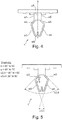
- FIG. 4 shows a side view of the mounting bracket of FIG. 2 , clearly showing the symmetry.
- FIG. 5 shows the same view on the bracket 1 as FIG. 4 , but indicates the angular distance ⁇ 3,4 between the wall sections w3 and w4 of the first pair of wall sections, and indicates the angular distance ⁇ 2,5 between the wall sections w2 and w5 of the second pair of wall sections.
- the angular distance ⁇ 3,4 of the first pair of wall sections is rather sharp for allowing easy engagement of the bracket and the connector
- the angular distance ⁇ 2,5 of the second pair of wall sections is 30° to 50° larger for retaining the bracket and the connector, while still allowing relatively easy disengagement of the bracket and the connector.
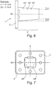
- FIG. 6 shows another side view of the mounting bracket of FIG. 2 , showing another optional feature, namely that the protruding portion 4 of the mounting bracket 1 is tapered.
- a virtual tangential plane contacting an (upper) side of the wall sections w1, w2, w3, w4, w5, w6 defines an angle ⁇ 1 in the range from 3° to 8° with respect to a plane parallel to the plane M
- a virtual tangential plane contacting a (lower) side of the wall sections w1, w2, w3, w4, w5, w6 defines an angle ⁇ 2 in the range from 3° to 8° with respect to a plane parallel to the plane M. This may allow for easier and faster positioning of a connector over the mounting bracket 1.
- the angle ⁇ 1 and ⁇ 2 may be the same angle or a different angle.
- FIG. 7 shows a top view of the mounting bracket of FIG. 2 .
- FIG. 8 shows a portion of an exemplary headliner assembly 20 comprising the mounting bracket of FIG. 2 .
- a vehicle headliner assembly 20 is shown in engagement with a roof or roof assembly 30 using an attachment system comprising brackets 1 and mating connectors 21.
- the exemplary connector 21 is connected to the headliner 26 in known manners, for example using an adhesive.
- the connector 21 comprises a base 22 and two flexible members 23, 24 oriented perpendicular to the base 22.
- the connector 21 comprises a first pair of wall sections w11, w12 located on the first and second flexible member 23, 24, respectively, for abutting the walls w3, w4 of the first pair of wall sections of the mounting bracket 1.
- the connector 21 also comprises a second pair of wall sections w13, w14 located on the first and second flexible member 23, 24, respectively, for abutting the walls w2, w5 of the second pair of wall sections of the mounting bracket 1.
- FIG. 8 the flexible members 23, 24 of the connector 21 are deliberately shown at a distance from the mounting bracket 1 for illustrative purposes, but in practice the flexible members clamp the mounting bracket 1.
- the wall section w11 and w13 are preferably interconnected via a curved transition, in order to reduce stress concentrations, for reducing the risk of braking the flexible members during mounting.
- the wall sections w11 and w13 on the first flexible member 23, and the wall sections w12 and w14 on the second flexible member 24 form two V-shapes for clamping the mounting bracket 1 between them in a resilient manner without requiring an additional resilient element for pushing the connector toward or away from the bracket 1.
- the V-shapes allow some movement, for example during vibrations, thereby reducing vibrational noise.
- the V-shapes also allow some tolerance of the dimensions of the bracket 1 and the connector 21.
- a length of the flexible members 23, 24 is chosen slightly smaller than the intended distance between the base plate 22 of the connector 21 and the base plate 2 of the mounting bracket 1.
- the first flexible member 23 has an additional wall section w15 substantially parallel to the wall section w11
- the second flexible member 24 has an additional wall section w16 substantially parallel to the wall section w12.
- the wall section w15 comes into contact with the wall section w3 and slides over w3
- the wall section w16 comes into contact with wall section w4 and slides over w4, while the flexible members 23, 24 are being pushed apart.
- the wall sections w15 and w16 may also be slightly curved (not shown), for minimizing the contact area with w3 and w4 when sliding, thereby reducing the friction force, and thus reducing the required force for mounting the headliner.
- the headliner 26 can be mounted to the roof assembly 30 by merely pushing the headliner 26 towards the roof 30, thereby engaging the connector 21 and the bracket 1.
- the headliner 26 can be dismounted by pulling the headliner 26 away from the roof or roof assembly 30. No further operations are required, such as having to unscrew a plurality of screws, or having to push lips together before pulling. It is pointed out that no access to the connector 21 or to the bracket 1 is required.
- connector 21 shown in FIG. 8 is very well suited for interconnection with the mounting bracket 1 described above, it is pointed out that embodiments of the present invention are not limited to this specific connector 21.
Landscapes
- Engineering & Computer Science (AREA)
- General Engineering & Computer Science (AREA)
- Mechanical Engineering (AREA)
- Vehicle Interior And Exterior Ornaments, Soundproofing, And Insulation (AREA)
Abstract
Description
- The present invention relates in general to a vehicle headliner attachment. The present invention relates more in particular to a mounting bracket that can be used in a vehicle headliner attachment. Specifically, the present invention provides a vehicle headliner assembly, and a mounting bracket that can be used in such a headliner assembly, and a vehicle comprising such a headliner assembly.
- Vehicles (e.g. a car or a truck or a boat) with a roof structure typically have a headliner assembly to provide an attractive appearance for the interior of the vehicle. Different manners of attachment are used in the art. Some manners are more difficult than others during manufacturing or repair.
-
JPH-04 278855 A -
US 3,889,320 A describes a one-piece headliner and moulding retainer for securing a headliner assembly adjacent the roof of an automobile. The roof structure is provided with an oval aperture. The retainer has an arrowhead-shaped mounting portion to be inserted in said aperture. -
CN 204567500 U discloses a connecting device for a roof lining and a skylight, which comprises a fixing frame, arranged on the back surface of the car roof and a card slot opened on the automobile sunroof, the fixed frame and the card slot are connected with each other, using one or more rails. -
US 2004/0256889 A1 discloses a method of manufacturing a vehicle body part that embeds an insert piece into a foamed layer of the body part by holding the insert piece in a foaming tool using a magnetic force. -
US 5,186,517 A describes a fastening arrangement for attaching components such as headliners, overhead consoles, or the like to vehicles. -
US 8,899,671 B2 describes a vehicle headliner attachment system including a moonroof assembly having a peripheral structure surrounding at least one glass panel. -
KR 100692748 B1 - There is always room for improvements and alternatives.
- The present invention has the object to provide a vehicle headliner assembly, and a mounting bracket for use in such headliner assembly, and a vehicle comprising such a headliner assembly.
- It is a particular object of embodiments of the present invention to provide a headliner assembly that is easier to install.
- It is a particular object of embodiments of the present invention to provide a headliner assembly not requiring a clip during installation.
- It is a particular object of embodiments of the present invention to provide a headliner assembly not requiring a locator during installation.
- It is a particular object of embodiments of the present invention to provide a headliner assembly that is serviceable.
- It is a particular object of embodiments of the present invention to provide a headliner assembly that is easier to dismount.
- These objects are achieved by a vehicle headliner assembly having the features of
claim 1, and by a mounting bracket having the features of claim 10, and by a vehicle having the features of claim 11. Further, particularly advantageous embodiments of the invention are disclosed in the dependent claims. - It should be noted that the individual features listed in the description below can be combined in any technically meaningful way with each other and show further embodiments of the invention. The description of the invention is additionally characterized and specified particularly in connection with the figures.
- In an advantageous embodiment, the present invention discloses a vehicle headliner assembly comprising a plurality of mounting brackets, each mounting bracket having a three-dimensional shape comprising a base plate and a protruding portion comprising a plurality of wall sections, wherein the mounting bracket has an omega-shaped cross-section; and the plurality of wall sections comprises a first pair of wall sections facing away from the base plate and defining an angle in the range from 30° to 50° for pushing apart two flexible members of a connector attached to a headliner when said headliner is being pushed towards the base plate; and the plurality of wall sections comprises a second pair of wall sections defining an angle in the range from 80° to 100° for holding the headliner by retaining said flexible members of said connector in a releasable manner.
- It is an advantage of the angle defined by the first pair of wall sections that they allow easy mounting of the headliner during production, by simply pushing the headliner towards the mounting brackets attached to the roof or roof structure.
- It is a further advantage of the angle defined by the second pair of wall sections that they allow relatively easy removal of the headliner, by a simple retraction force, for example for repairing the headliner, without damaging the flexible members of the connector of the headliner.
- If is a further advantage that the angle defined by the second pair is considerably larger (e.g. at least 30° larger) than the angle defined by the first pair, such that a pulling force required to dismount the headliner needs to be significantly larger than the force required to mount the headliner. In this way, the risk of inadvertent disengagement is strongly reduced.
- According to a further advantageous embodiment of the present invention, the vehicle headliner assembly further comprises said headliner and a plurality of connectors connected thereto, for engaging with said plurality of brackets.
- According to a further advantageous embodiment of the present invention, the flexible members of the connectors comprise a first pair of wall sections for abutting the first pair of wall sections of the mounting bracket; and the flexible members of the connectors comprise a second pair of wall sections for abutting the second pair of wall sections of the mounting bracket; and the wall sections of the first pair and the wall sections of the second pair form two V-shapes for clamping the mounting bracket between them.
- It is an advantage of the angular positions of the wall sections of the flexible members that they induce a clamping force that urges the headliner in its default distance relative to the mounting bracket, without requiring an additional resilient element. In this way, component cost can be reduced and vibrational noise can be reduced.
- According to a further advantageous embodiment of the present invention, the second pair of wall sections of the bracket is connected to the base plate via two further wall sections each oriented substantially perpendicular to the base plate of the mounting bracket; and wherein these two further wall sections are interconnected via an interconnection wall also oriented substantially perpendicular to the base plate so as to define a U-shaped cross section in a plane parallel to the base plate.
- It is an advantage that the second pair of wall sections is mounted to the base plate via three further wall sections forming a U-shaped cross section in a plane parallel to the base plate, rather than via only two separate wall sections, because the U-shape improves the rigidity of the structure, in particular against a force in a direction parallel to the base plate. The interconnection wall not only prevents the omega-shape from widening, but also offers resistance to bending of the protruding portion due to a shear force exerted upon the headliner.
- It is a further advantage that the second pair of wall sections is mounted to the base plate via three further wall sections forming a U-shaped cross section, rather than via four wall sections forming a tube with a rectangular cross section, because the U-shape still allows some flexibility of the 3D-structure, which is advantageous for example to absorb vibrations, and/or when dismounting the headliner.
- According to a further advantageous embodiment of the present invention, the flexible members of the connector comprise a third pair of wall sections each being substantially parallel to a respective wall section of the first pair of wall sections of the connector.
- It is an advantage of this third pair of wall sections that they allow easy sliding and urge opening of the flexible members when the headliner is being mounted to the bracket.
- According to an alternative advantageous embodiment of the present invention, the flexible members of the connectors comprise a third pair of curved wall sections located at a distal end of the flexible members.
- It is an advantage of a curved wall section, more in particular convexly curved, that a friction force exerted between the contacting surfaces of the bracket and of the connector due to sliding during mounting of the headliner can be reduced by minimizing the contact area between these surfaces.
- According to a further advantageous embodiment of the present invention, a virtual tangential plane contacting a side or end face of the walls of the first pair of the bracket and simultaneously contacting a side or end face of the walls of the second pair of the bracket defines an angle in the range from 3° to 8° with respect to a plane perpendicular to the base plate of the bracket.
- It is an advantage that the three-dimensional shape is tapered, because this allows to easier position a connector with a rectangular opening over the mounting bracket.
- According to a further advantageous embodiment of the present invention, the bracket is manufactured as an integral piece of material.
- It is an advantage that such a bracket is easy to manufacture, and is stronger and the risk of parts braking of is reduced.
- According to a further advantageous embodiment of the present invention, the base plate has a plurality of openings.
- It is an advantage of these openings, that they allow easy attachment of the bracket to a roof or roof assembly.
- According to another advantageous embodiment of the present invention, the present invention discloses a mounting bracket for use in the vehicle headliner assembly described above.
- According to another advantageous embodiment of the present invention, the present invention discloses a vehicle comprising a vehicle headliner assembly described above.
- Further features and advantages of the present invention will become apparent from the following description of a non-limiting embodiment of the invention which will be explained below with reference to the drawing, wherein:
- FIG. 1
- shows a roof structure comprising a plurality of mounting brackets (only two of which are visible in
FIG. 1 ) according to the present invention, for mounting a headliner. - FIG.2
- shows a perspective view of a mounting bracket according to the present invention.
- FIG. 3
- shows another perspective view of the mounting bracket of
FIG. 2 . - FIG. 4
- shows a side view of the mounting bracket of
FIG. 2 , having a plurality of wall sections. - FIG. 5
- is the same view as
FIG. 4 , showing angular distances between a first and second pair of wall sections. - FIG. 6
- shows another side view of the mounting bracket of
FIG. 2 . - FIG. 7
- shows a top view of the mounting bracket of
FIG. 2 . - FIG. 8
- shows an exemplary headliner assembly comprising the mounting bracket of
FIG. 2 . - In the various figures, equivalent elements with respect to their function are always provided with the same reference numerals so that these elements are usually described only once.
- The present invention is related to a vehicle headliner attachment. The present invention relates more in particular to a mounting bracket that can be used in a vehicle headliner attachment system.
-
FIG. 1 shows aroof structure 30 comprising a plurality of mountingbrackets 1 for mounting a headliner 26 (seeFIG. 8 ), but only two mountingbrackets FIG. 1 . In practice, typically a plurality of at least eight, for example ten or twelve of such mountingbrackets 1 are attached to the roof orroof structure 30. Thebrackets 1 are typically arranged on the periphery of a rectangular region, for example four or five on each longitudinal side and two or three on each lateral side of the rectangle. -
FIG. 2 shows a perspective view of a mountingbracket 1 according to the present invention. - The mounting
bracket 1 has a three-dimensional shape comprising abase plate 2, and a protrudingportion 4 extending from thebase plate 2. - Two virtual planes are indicated in the drawing, a plane M oriented perpendicular to the
base plate 2 and running through the middle of the lateral side of thebracket 1, and a plane S oriented perpendicular to thebase plate 2 and running through the middle of the longitudinal side of the mountingbracket 1. The plane S is a plane of symmetry. The plane M is not a plane of symmetry because of the presence of the wall section w7, as will be explained further below. - A cross section of the mounting
bracket 1 in the plane M defines an omega-like shape, formed by the plurality of wall sections w1-w2-w3-w8-w4-w5-w6. The wall section w7 does not participate in the formation of the omega-like shape. - The plurality of wall sections comprises a first pair of wall sections w3, w4 facing away (upwards in
FIG. 2 ) from thebase plate 2, and defining an angle α3,4 (better shown inFIG. 5 ) in the range from 30° to 50°, preferably in the range from 35° to 45°, for example equal to about 40° for pushing apart twoflexible members 23, 24 (seeFIG. 8 ) of aconnector 21 attached to aheadliner 26 when saidheadliner 26 and thus also theconnector 21 is being pushed towards thebase plate 2 of thebracket 1 attached to the roof structure. The wall sections w3, w4 are located on opposite sides of the symmetry plane S. - The plurality of wall sections further comprises a second pair of wall sections w2, w5 defining an angle α2,5 in the range from 80° to 100° (see
FIG. 5 ), preferably in the range from 85° to 95°, for example equal to about 90° for retaining saidflexible members connector 21 after mounting theheadliner 26 to the roof structure, thus after engagement of thebrackets 1 and theconnectors 21. Using an angle in the range from 80° to 100° rather than an almost straight angle of 180° (as is the case inUS 8,899,671 B2 ) offers the major advantage that the headliner can be easily released from the roof structure, should that be necessary, for example during car manufacturing or during repair afterwards. - As shown in
FIG. 2 , the wall sections w3 and w4 are preferably interconnected via a convexly curved wall section w8, in order to reduce stress concentrations. The same applies for the interconnection between the wall sections w2 and w3, and between the wall sections w4 and w5. - As can be seen, the second pair of wall sections w2, w5 is not mounted directly to the
base plate 2, but indirectly via two further wall sections w1, w6 each oriented substantially perpendicular to thebase plate 2 of the mountingbracket 1. In particular, the wall section w2 is adjacent wall section w1, and the wall section w5 is adjacent wall section w6. This allows to create some spacing between thebase plate 2 and the second pair of wall sections w2, w5 for reasons that will be described further below. The wall sections w1, w6 are preferably parallel to the symmetry plane S, hence perpendicular to thebase plate 2. - Preferably, the further wall sections w1 and w6 are interconnected via an interconnection wall section w7 which is oriented substantially perpendicular to the
base plate 2, parallel to the plane M. The wall sections w1 and w7 and w6 form a U-shaped cross-section in a plane parallel to thebase plate 2. This provides extra rigidity to the protrudingportion 4. - Preferably the mounting
bracket 1 is manufactured as an integral piece of material, for example metal or a plastic material, preferably a thermoset plastic material. - Preferably the
base plate 2 has a plurality ofopenings 3 for mounting thebracket 1 to a roof orroof structure 30. In the example shown, the mounting bracket has eight openings, but that is not absolutely required, and fewer openings, for example four openings, one near each corner of thebase plate 2, may also be sufficient. The mountingbracket 1 can be attached to the roof in any known manner, for example using rivets or screws, or in case of metal, by spot welding, or using glue or an adhesive, or in any other way. When using glue or an adhesive, theopenings 3 can be omitted. - The mounting
bracket 2 may optionally further comprise a plurality of spacer blocks 5, for coming into contact with a distal end of theflexible members connector 21 when the latter is being pushed towards thebase plate 2 during mounting of theheadliner 26. The height of thesespacer blocks 5 in a direction perpendicular to thebase plate 2 is preferably in the range from 4 to 8 mm, for example equal to about 6 mm, which is typically higher than the height of the heads of the screws or rivets or spot welds (not shown). -
FIG. 3 shows another perspective view of the mounting bracket ofFIG. 2 . -
FIG. 4 shows a side view of the mounting bracket ofFIG. 2 , clearly showing the symmetry. -
FIG. 5 shows the same view on thebracket 1 asFIG. 4 , but indicates the angular distance α3,4 between the wall sections w3 and w4 of the first pair of wall sections, and indicates the angular distance α2,5 between the wall sections w2 and w5 of the second pair of wall sections. As can be seen, the angular distance α3,4 of the first pair of wall sections is rather sharp for allowing easy engagement of the bracket and the connector, and the angular distance α2,5 of the second pair of wall sections is 30° to 50° larger for retaining the bracket and the connector, while still allowing relatively easy disengagement of the bracket and the connector. -
FIG. 6 shows another side view of the mounting bracket ofFIG. 2 , showing another optional feature, namely that the protrudingportion 4 of the mountingbracket 1 is tapered. As shown, a virtual tangential plane contacting an (upper) side of the wall sections w1, w2, w3, w4, w5, w6 defines an angle β1 in the range from 3° to 8° with respect to a plane parallel to the plane M, and a virtual tangential plane contacting a (lower) side of the wall sections w1, w2, w3, w4, w5, w6 defines an angle β2 in the range from 3° to 8° with respect to a plane parallel to the plane M. This may allow for easier and faster positioning of a connector over the mountingbracket 1. The angle β1 and β2 may be the same angle or a different angle. -
FIG. 7 shows a top view of the mounting bracket ofFIG. 2 . -
FIG. 8 shows a portion of anexemplary headliner assembly 20 comprising the mounting bracket ofFIG. 2 . - In the drawing of
FIG. 8 , avehicle headliner assembly 20 is shown in engagement with a roof orroof assembly 30 using an attachmentsystem comprising brackets 1 andmating connectors 21. Theexemplary connector 21 is connected to theheadliner 26 in known manners, for example using an adhesive. - The
connector 21 comprises abase 22 and twoflexible members base 22. Theconnector 21 comprises a first pair of wall sections w11, w12 located on the first and secondflexible member bracket 1. - The
connector 21 also comprises a second pair of wall sections w13, w14 located on the first and secondflexible member bracket 1. - In
FIG. 8 theflexible members connector 21 are deliberately shown at a distance from the mountingbracket 1 for illustrative purposes, but in practice the flexible members clamp the mountingbracket 1. - As shown, the wall section w11 and w13 are preferably interconnected via a curved transition, in order to reduce stress concentrations, for reducing the risk of braking the flexible members during mounting.
- As shown, the wall sections w11 and w13 on the first
flexible member 23, and the wall sections w12 and w14 on the secondflexible member 24 form two V-shapes for clamping the mountingbracket 1 between them in a resilient manner without requiring an additional resilient element for pushing the connector toward or away from thebracket 1. The V-shapes allow some movement, for example during vibrations, thereby reducing vibrational noise. The V-shapes also allow some tolerance of the dimensions of thebracket 1 and theconnector 21. - As can be understood from
FIG. 8 , preferably a length of theflexible members base plate 22 of theconnector 21 and thebase plate 2 of the mountingbracket 1. - Preferably the first
flexible member 23 has an additional wall section w15 substantially parallel to the wall section w11, and the secondflexible member 24 has an additional wall section w16 substantially parallel to the wall section w12. During mounting of theheadliner 26, the wall section w15 comes into contact with the wall section w3 and slides over w3, and the wall section w16 comes into contact with wall section w4 and slides over w4, while theflexible members - Alternatively, rather than straight, the wall sections w15 and w16 may also be slightly curved (not shown), for minimizing the contact area with w3 and w4 when sliding, thereby reducing the friction force, and thus reducing the required force for mounting the headliner.
- The skilled person can appreciate from
FIG. 8 that theheadliner 26 can be mounted to theroof assembly 30 by merely pushing theheadliner 26 towards theroof 30, thereby engaging theconnector 21 and thebracket 1. - The skilled person will also appreciate that the
headliner 26 can be dismounted by pulling theheadliner 26 away from the roof orroof assembly 30. No further operations are required, such as having to unscrew a plurality of screws, or having to push lips together before pulling. It is pointed out that no access to theconnector 21 or to thebracket 1 is required. - Although the
connector 21 shown inFIG. 8 is very well suited for interconnection with the mountingbracket 1 described above, it is pointed out that embodiments of the present invention are not limited to thisspecific connector 21. -
- 1, 1a, 1b: mounting bracket,
- 2: base plate,
- 3: opening,
- 4: protruding portion,
- 5: spacers,
- w1-w8: wall sections of the mounting bracket,
- S: symmetry plane,
- M: plane perpendicular to the symmetry plane,
- 20: vehicle headliner assembly,
- 21: connector,
- 22: base of the connector,
- 23, 24: flexible members of the connector,
- 25: adhesive of tape or the like,
- 26: headliner,
- w11-w16: wall sections of the connector,
- 30: roof or roof structure.
Claims (11)
- A vehicle headliner assembly (20) comprising a plurality of mounting brackets (1), each mounting bracket (1) having a three-dimensional shape comprising a base plate (2) and a protruding portion (4) comprising a plurality of wall sections,
characterised in, that- the mounting bracket has an omega-shaped cross-section;- the plurality of wall sections comprises a first pair of wall sections (w3, w4) facing away from the base plate (2) and defining an angle (α3,4) in the range from 30° to 50° for pushing apart two flexible members (23, 24) of a connector (21) attached to a headliner (26) when said headliner is being pushed towards the base plate (2); and- the plurality of wall sections comprises a second pair of wall sections (w2, w5) defining an angle (α2,5) in the range from 80° to 100° for holding the headliner by retaining said flexible members (23, 24) of said connector (21) in a releasable manner. - A vehicle headliner assembly (20) according to claim 1,
further comprising said headliner (26) and a plurality of connectors (21) connected thereto, for engaging with said plurality of brackets (1). - A vehicle headliner assembly (20) according to claim 1 or 2,
characterized in, that
the flexible members (23, 24) of the connectors (21) comprise a first pair of wall sections (w11, w12) for abutting the first pair of wall sections (w3, w4) of the mounting bracket (1);
wherein the flexible members (23, 24) of the connectors (21) comprise a second pair of wall sections (w13, w14) for abutting the second pair of wall sections (w2, w5) of the mounting bracket (1);
and wherein the wall sections (w11, w12) of the first pair and the wall sections (w13, w14) of the second pair form two V-shapes for clamping the mounting bracket between them. - A vehicle headliner assembly (20) according to any of the previous claims,
characterized in, that
the second pair of wall sections (w2, w5) of the bracket (1) is connected to the base plate (2) via two further wall sections (w1, w6) each oriented substantially perpendicular to the base plate (2) of the mounting bracket (1);
wherein these two further wall sections (w1, w6) are interconnected via an interconnection wall (w7) also oriented substantially perpendicular to the base plate so as to define a U-shaped cross section in a plane parallel to the base plate (2). - A vehicle headliner assembly (20) according to any of the previous claims,
characterized in, that
the flexible members (23, 24) of the connectors (21) comprise a third pair of wall sections (w15, w16) each being substantially parallel to a respective wall section of the first pair of wall sections (w11, w12). - A vehicle headliner assembly (20) according to any of the claims 1 to 4,
characterized in, that
the flexible members (23, 24) of the connectors (21) comprise a third pair of curved wall sections (w15, w16), located at a distal end of the flexible members (23, 24). - A vehicle headliner assembly (20) according to any of the previous claims,
characterized by
a virtual tangential plane contacting a side of the walls of the first pair (w3, w4) of the bracket (1) and simultaneously contacting a side of the walls of the second pair (w2, w5) of the bracket (1) defines an angle (β1) in the range from 3° to 8° with respect to a plane perpendicular to the base plate (2) of the bracket (1). - A vehicle headliner assembly (20) according to any of the previous claims,
characterized in, that
the bracket (1) is manufactured as an integral piece of material. - A vehicle headliner assembly (20) according to any of the previous claims,
characterized in, that
the base plate (2) has a plurality of openings (3). - A mounting bracket (1) for use in the vehicle headliner assembly (20) according to any of the previous claims.
- A vehicle comprising a vehicle headliner assembly (20) according to any of the claims 1 to 9.
Priority Applications (1)
| Application Number | Priority Date | Filing Date | Title |
|---|---|---|---|
| EP18155099.7A EP3521641B1 (en) | 2018-02-05 | 2018-02-05 | Vehicle headliner attachment |
Applications Claiming Priority (1)
| Application Number | Priority Date | Filing Date | Title |
|---|---|---|---|
| EP18155099.7A EP3521641B1 (en) | 2018-02-05 | 2018-02-05 | Vehicle headliner attachment |
Publications (2)
| Publication Number | Publication Date |
|---|---|
| EP3521641A1 true EP3521641A1 (en) | 2019-08-07 |
| EP3521641B1 EP3521641B1 (en) | 2020-08-26 |
Family
ID=61163561
Family Applications (1)
| Application Number | Title | Priority Date | Filing Date |
|---|---|---|---|
| EP18155099.7A Active EP3521641B1 (en) | 2018-02-05 | 2018-02-05 | Vehicle headliner attachment |
Country Status (1)
| Country | Link |
|---|---|
| EP (1) | EP3521641B1 (en) |
Cited By (1)
| Publication number | Priority date | Publication date | Assignee | Title |
|---|---|---|---|---|
| WO2022017978A1 (en) | 2020-07-22 | 2022-01-27 | Volkswagen Aktiengesellschaft | Fastening arrangement, motor vehicle |
Citations (15)
| Publication number | Priority date | Publication date | Assignee | Title |
|---|---|---|---|---|
| US3889320A (en) | 1974-04-01 | 1975-06-17 | Illinois Tool Works | Headliner/molding retainer and method of installing same |
| JPH04208656A (en) * | 1990-11-30 | 1992-07-30 | Sanwa Kogyo Kk | Fitting of fixture on roof lining for automobile |
| US5186517A (en) | 1992-03-05 | 1993-02-16 | Prince Corporation | Shiftable/releasable mount |
| US5876084A (en) * | 1997-07-15 | 1999-03-02 | Prince Corporation | Panel mounting clip |
| WO2000020255A1 (en) * | 1998-10-07 | 2000-04-13 | Lear Corporation | Modular headliner with self-aligning lamp |
| US20040256889A1 (en) | 2003-06-23 | 2004-12-23 | Horst Schonebeck | Foamed vehicle part and method of manufacturing |
| DE10335220A1 (en) * | 2003-08-01 | 2005-03-10 | Opel Eisenach Gmbh | Device for connecting a motor vehicle roof to a frame of a sliding roof has two part fixing strip connected to both the frame and roof |
| US20060168773A1 (en) * | 2001-06-25 | 2006-08-03 | Termax Corporation | Multicontact Adaptive Fastener Clip |
| KR100692748B1 (en) | 2001-01-29 | 2007-03-09 | 그루포 안톨린-인제니리아 에스. 에이. | Freestanding car ceiling fixtures |
| WO2009064711A2 (en) * | 2007-11-15 | 2009-05-22 | 3M Innovative Properties Company | Multi-angle pop-in mechanical fastener |
| DE102008052965A1 (en) * | 2008-10-23 | 2010-04-29 | Volkswagen Ag | Device for fastening roof lining at panorama roof or sun roof of motor vehicle, has body parts connected with each other in form-fit manner such that movement between parts is permitted for compensating tolerances in directions |
| DE102010033849A1 (en) * | 2010-08-09 | 2012-02-09 | Trw Automotive Electronics & Components Gmbh | Retaining clip for mounting covering part to body part, and for use in subassembly, has holding section with undercut which is latched behind latching element |
| DE102012017096A1 (en) * | 2012-08-29 | 2014-03-06 | GM Global Technology Operations, LLC (n.d. Ges. d. Staates Delaware) | Mounting element for mounting roof head lining to roof shell plate of vehicle, has centering pin via which connectable base plate provided on roof head lining is connected to roof shell plate of vehicle |
| US8899671B2 (en) | 2013-03-14 | 2014-12-02 | Ford Global Technologies, Llc | Vehicle headliner attachment system |
| CN204567500U (en) | 2015-03-12 | 2015-08-19 | 上海通用汽车有限公司 | The connecting device in a kind of automobile roof liner and skylight |
-
2018
- 2018-02-05 EP EP18155099.7A patent/EP3521641B1/en active Active
Patent Citations (15)
| Publication number | Priority date | Publication date | Assignee | Title |
|---|---|---|---|---|
| US3889320A (en) | 1974-04-01 | 1975-06-17 | Illinois Tool Works | Headliner/molding retainer and method of installing same |
| JPH04208656A (en) * | 1990-11-30 | 1992-07-30 | Sanwa Kogyo Kk | Fitting of fixture on roof lining for automobile |
| US5186517A (en) | 1992-03-05 | 1993-02-16 | Prince Corporation | Shiftable/releasable mount |
| US5876084A (en) * | 1997-07-15 | 1999-03-02 | Prince Corporation | Panel mounting clip |
| WO2000020255A1 (en) * | 1998-10-07 | 2000-04-13 | Lear Corporation | Modular headliner with self-aligning lamp |
| KR100692748B1 (en) | 2001-01-29 | 2007-03-09 | 그루포 안톨린-인제니리아 에스. 에이. | Freestanding car ceiling fixtures |
| US20060168773A1 (en) * | 2001-06-25 | 2006-08-03 | Termax Corporation | Multicontact Adaptive Fastener Clip |
| US20040256889A1 (en) | 2003-06-23 | 2004-12-23 | Horst Schonebeck | Foamed vehicle part and method of manufacturing |
| DE10335220A1 (en) * | 2003-08-01 | 2005-03-10 | Opel Eisenach Gmbh | Device for connecting a motor vehicle roof to a frame of a sliding roof has two part fixing strip connected to both the frame and roof |
| WO2009064711A2 (en) * | 2007-11-15 | 2009-05-22 | 3M Innovative Properties Company | Multi-angle pop-in mechanical fastener |
| DE102008052965A1 (en) * | 2008-10-23 | 2010-04-29 | Volkswagen Ag | Device for fastening roof lining at panorama roof or sun roof of motor vehicle, has body parts connected with each other in form-fit manner such that movement between parts is permitted for compensating tolerances in directions |
| DE102010033849A1 (en) * | 2010-08-09 | 2012-02-09 | Trw Automotive Electronics & Components Gmbh | Retaining clip for mounting covering part to body part, and for use in subassembly, has holding section with undercut which is latched behind latching element |
| DE102012017096A1 (en) * | 2012-08-29 | 2014-03-06 | GM Global Technology Operations, LLC (n.d. Ges. d. Staates Delaware) | Mounting element for mounting roof head lining to roof shell plate of vehicle, has centering pin via which connectable base plate provided on roof head lining is connected to roof shell plate of vehicle |
| US8899671B2 (en) | 2013-03-14 | 2014-12-02 | Ford Global Technologies, Llc | Vehicle headliner attachment system |
| CN204567500U (en) | 2015-03-12 | 2015-08-19 | 上海通用汽车有限公司 | The connecting device in a kind of automobile roof liner and skylight |
Cited By (3)
| Publication number | Priority date | Publication date | Assignee | Title |
|---|---|---|---|---|
| WO2022017978A1 (en) | 2020-07-22 | 2022-01-27 | Volkswagen Aktiengesellschaft | Fastening arrangement, motor vehicle |
| DE102020209264A1 (en) | 2020-07-22 | 2022-01-27 | Volkswagen Aktiengesellschaft | Fastening arrangement, motor vehicle |
| US12415467B2 (en) | 2020-07-22 | 2025-09-16 | Volkswagen Aktiengesellschaft | Fastening arrangement, motor vehicle |
Also Published As
| Publication number | Publication date |
|---|---|
| EP3521641B1 (en) | 2020-08-26 |
Similar Documents
| Publication | Publication Date | Title |
|---|---|---|
| CA2539425C (en) | Vehicle body panel with integral clip | |
| CN102868073A (en) | Connector supporting tool, wiring tool and wiring harness | |
| JP5994646B2 (en) | Mounting structure for vehicle interior parts | |
| JPH0557407U (en) | Fixing structure for mounting members | |
| US20070277944A1 (en) | Curtain track assembly | |
| EP3521641B1 (en) | Vehicle headliner attachment | |
| CN109720416B (en) | Vehicle roof connection device | |
| JP3983464B2 (en) | Roof module structure | |
| EP1798113A2 (en) | Vehicle molding clip mounting structure | |
| KR102456787B1 (en) | Coupled structure od fastener holder and fastener | |
| JP5044325B2 (en) | Automotive interior structure | |
| JP3677967B2 (en) | Molded ceiling mounting structure | |
| KR200141961Y1 (en) | Car clip structure | |
| KR100794036B1 (en) | Windshield glass side molding bracket coupling structure of automobile | |
| JP2001191861A (en) | Interior trim mounting structure | |
| JPH0517322Y2 (en) | ||
| KR20240079393A (en) | Module clip for vehicles | |
| JP2538059Y2 (en) | Mall mounting structure | |
| JPH0571671A (en) | Clip for wire harness | |
| JP2991278B2 (en) | Eave gutter fitting | |
| JPH11263124A (en) | Wind glass garnish fixing structure for vehicles | |
| JP2607247Y2 (en) | Automotive window glass mounting device | |
| JP2008184046A (en) | Automotive visor mounting bracket | |
| JP2009298352A (en) | Shock absorbing member | |
| JP2009143604A (en) | Cable ties |
Legal Events
| Date | Code | Title | Description |
|---|---|---|---|
| PUAI | Public reference made under article 153(3) epc to a published international application that has entered the european phase |
Free format text: ORIGINAL CODE: 0009012 |
|
| STAA | Information on the status of an ep patent application or granted ep patent |
Free format text: STATUS: THE APPLICATION HAS BEEN PUBLISHED |
|
| AK | Designated contracting states |
Kind code of ref document: A1 Designated state(s): AL AT BE BG CH CY CZ DE DK EE ES FI FR GB GR HR HU IE IS IT LI LT LU LV MC MK MT NL NO PL PT RO RS SE SI SK SM TR |
|
| AX | Request for extension of the european patent |
Extension state: BA ME |
|
| STAA | Information on the status of an ep patent application or granted ep patent |
Free format text: STATUS: REQUEST FOR EXAMINATION WAS MADE |
|
| 17P | Request for examination filed |
Effective date: 20200207 |
|
| RBV | Designated contracting states (corrected) |
Designated state(s): AL AT BE BG CH CY CZ DE DK EE ES FI FR GB GR HR HU IE IS IT LI LT LU LV MC MK MT NL NO PL PT RO RS SE SI SK SM TR |
|
| GRAP | Despatch of communication of intention to grant a patent |
Free format text: ORIGINAL CODE: EPIDOSNIGR1 |
|
| STAA | Information on the status of an ep patent application or granted ep patent |
Free format text: STATUS: GRANT OF PATENT IS INTENDED |
|
| INTG | Intention to grant announced |
Effective date: 20200508 |
|
| GRAS | Grant fee paid |
Free format text: ORIGINAL CODE: EPIDOSNIGR3 |
|
| GRAA | (expected) grant |
Free format text: ORIGINAL CODE: 0009210 |
|
| STAA | Information on the status of an ep patent application or granted ep patent |
Free format text: STATUS: THE PATENT HAS BEEN GRANTED |
|
| AK | Designated contracting states |
Kind code of ref document: B1 Designated state(s): AL AT BE BG CH CY CZ DE DK EE ES FI FR GB GR HR HU IE IS IT LI LT LU LV MC MK MT NL NO PL PT RO RS SE SI SK SM TR |
|
| REG | Reference to a national code |
Ref country code: GB Ref legal event code: FG4D |
|
| REG | Reference to a national code |
Ref country code: CH Ref legal event code: EP |
|
| REG | Reference to a national code |
Ref country code: AT Ref legal event code: REF Ref document number: 1306649 Country of ref document: AT Kind code of ref document: T Effective date: 20200915 |
|
| REG | Reference to a national code |
Ref country code: IE Ref legal event code: FG4D |
|
| REG | Reference to a national code |
Ref country code: DE Ref legal event code: R096 Ref document number: 602018007159 Country of ref document: DE |
|
| REG | Reference to a national code |
Ref country code: LT Ref legal event code: MG4D |
|
| PG25 | Lapsed in a contracting state [announced via postgrant information from national office to epo] |
Ref country code: HR Free format text: LAPSE BECAUSE OF FAILURE TO SUBMIT A TRANSLATION OF THE DESCRIPTION OR TO PAY THE FEE WITHIN THE PRESCRIBED TIME-LIMIT Effective date: 20200826 Ref country code: SE Free format text: LAPSE BECAUSE OF FAILURE TO SUBMIT A TRANSLATION OF THE DESCRIPTION OR TO PAY THE FEE WITHIN THE PRESCRIBED TIME-LIMIT Effective date: 20200826 Ref country code: GR Free format text: LAPSE BECAUSE OF FAILURE TO SUBMIT A TRANSLATION OF THE DESCRIPTION OR TO PAY THE FEE WITHIN THE PRESCRIBED TIME-LIMIT Effective date: 20201127 Ref country code: NO Free format text: LAPSE BECAUSE OF FAILURE TO SUBMIT A TRANSLATION OF THE DESCRIPTION OR TO PAY THE FEE WITHIN THE PRESCRIBED TIME-LIMIT Effective date: 20201126 Ref country code: BG Free format text: LAPSE BECAUSE OF FAILURE TO SUBMIT A TRANSLATION OF THE DESCRIPTION OR TO PAY THE FEE WITHIN THE PRESCRIBED TIME-LIMIT Effective date: 20201126 Ref country code: LT Free format text: LAPSE BECAUSE OF FAILURE TO SUBMIT A TRANSLATION OF THE DESCRIPTION OR TO PAY THE FEE WITHIN THE PRESCRIBED TIME-LIMIT Effective date: 20200826 Ref country code: FI Free format text: LAPSE BECAUSE OF FAILURE TO SUBMIT A TRANSLATION OF THE DESCRIPTION OR TO PAY THE FEE WITHIN THE PRESCRIBED TIME-LIMIT Effective date: 20200826 Ref country code: PT Free format text: LAPSE BECAUSE OF FAILURE TO SUBMIT A TRANSLATION OF THE DESCRIPTION OR TO PAY THE FEE WITHIN THE PRESCRIBED TIME-LIMIT Effective date: 20201228 |
|
| REG | Reference to a national code |
Ref country code: NL Ref legal event code: MP Effective date: 20200826 |
|
| REG | Reference to a national code |
Ref country code: AT Ref legal event code: MK05 Ref document number: 1306649 Country of ref document: AT Kind code of ref document: T Effective date: 20200826 |
|
| PG25 | Lapsed in a contracting state [announced via postgrant information from national office to epo] |
Ref country code: IS Free format text: LAPSE BECAUSE OF FAILURE TO SUBMIT A TRANSLATION OF THE DESCRIPTION OR TO PAY THE FEE WITHIN THE PRESCRIBED TIME-LIMIT Effective date: 20201226 Ref country code: LV Free format text: LAPSE BECAUSE OF FAILURE TO SUBMIT A TRANSLATION OF THE DESCRIPTION OR TO PAY THE FEE WITHIN THE PRESCRIBED TIME-LIMIT Effective date: 20200826 Ref country code: RS Free format text: LAPSE BECAUSE OF FAILURE TO SUBMIT A TRANSLATION OF THE DESCRIPTION OR TO PAY THE FEE WITHIN THE PRESCRIBED TIME-LIMIT Effective date: 20200826 Ref country code: PL Free format text: LAPSE BECAUSE OF FAILURE TO SUBMIT A TRANSLATION OF THE DESCRIPTION OR TO PAY THE FEE WITHIN THE PRESCRIBED TIME-LIMIT Effective date: 20200826 Ref country code: NL Free format text: LAPSE BECAUSE OF FAILURE TO SUBMIT A TRANSLATION OF THE DESCRIPTION OR TO PAY THE FEE WITHIN THE PRESCRIBED TIME-LIMIT Effective date: 20200826 |
|
| PG25 | Lapsed in a contracting state [announced via postgrant information from national office to epo] |
Ref country code: CZ Free format text: LAPSE BECAUSE OF FAILURE TO SUBMIT A TRANSLATION OF THE DESCRIPTION OR TO PAY THE FEE WITHIN THE PRESCRIBED TIME-LIMIT Effective date: 20200826 Ref country code: DK Free format text: LAPSE BECAUSE OF FAILURE TO SUBMIT A TRANSLATION OF THE DESCRIPTION OR TO PAY THE FEE WITHIN THE PRESCRIBED TIME-LIMIT Effective date: 20200826 Ref country code: RO Free format text: LAPSE BECAUSE OF FAILURE TO SUBMIT A TRANSLATION OF THE DESCRIPTION OR TO PAY THE FEE WITHIN THE PRESCRIBED TIME-LIMIT Effective date: 20200826 Ref country code: EE Free format text: LAPSE BECAUSE OF FAILURE TO SUBMIT A TRANSLATION OF THE DESCRIPTION OR TO PAY THE FEE WITHIN THE PRESCRIBED TIME-LIMIT Effective date: 20200826 Ref country code: SM Free format text: LAPSE BECAUSE OF FAILURE TO SUBMIT A TRANSLATION OF THE DESCRIPTION OR TO PAY THE FEE WITHIN THE PRESCRIBED TIME-LIMIT Effective date: 20200826 |
|
| REG | Reference to a national code |
Ref country code: DE Ref legal event code: R097 Ref document number: 602018007159 Country of ref document: DE |
|
| PG25 | Lapsed in a contracting state [announced via postgrant information from national office to epo] |
Ref country code: AT Free format text: LAPSE BECAUSE OF FAILURE TO SUBMIT A TRANSLATION OF THE DESCRIPTION OR TO PAY THE FEE WITHIN THE PRESCRIBED TIME-LIMIT Effective date: 20200826 Ref country code: AL Free format text: LAPSE BECAUSE OF FAILURE TO SUBMIT A TRANSLATION OF THE DESCRIPTION OR TO PAY THE FEE WITHIN THE PRESCRIBED TIME-LIMIT Effective date: 20200826 Ref country code: ES Free format text: LAPSE BECAUSE OF FAILURE TO SUBMIT A TRANSLATION OF THE DESCRIPTION OR TO PAY THE FEE WITHIN THE PRESCRIBED TIME-LIMIT Effective date: 20200826 |
|
| PG25 | Lapsed in a contracting state [announced via postgrant information from national office to epo] |
Ref country code: SK Free format text: LAPSE BECAUSE OF FAILURE TO SUBMIT A TRANSLATION OF THE DESCRIPTION OR TO PAY THE FEE WITHIN THE PRESCRIBED TIME-LIMIT Effective date: 20200826 |
|
| PLBE | No opposition filed within time limit |
Free format text: ORIGINAL CODE: 0009261 |
|
| STAA | Information on the status of an ep patent application or granted ep patent |
Free format text: STATUS: NO OPPOSITION FILED WITHIN TIME LIMIT |
|
| PG25 | Lapsed in a contracting state [announced via postgrant information from national office to epo] |
Ref country code: IT Free format text: LAPSE BECAUSE OF FAILURE TO SUBMIT A TRANSLATION OF THE DESCRIPTION OR TO PAY THE FEE WITHIN THE PRESCRIBED TIME-LIMIT Effective date: 20200826 |
|
| 26N | No opposition filed |
Effective date: 20210527 |
|
| PG25 | Lapsed in a contracting state [announced via postgrant information from national office to epo] |
Ref country code: SI Free format text: LAPSE BECAUSE OF FAILURE TO SUBMIT A TRANSLATION OF THE DESCRIPTION OR TO PAY THE FEE WITHIN THE PRESCRIBED TIME-LIMIT Effective date: 20200826 |
|
| PG25 | Lapsed in a contracting state [announced via postgrant information from national office to epo] |
Ref country code: MC Free format text: LAPSE BECAUSE OF FAILURE TO SUBMIT A TRANSLATION OF THE DESCRIPTION OR TO PAY THE FEE WITHIN THE PRESCRIBED TIME-LIMIT Effective date: 20200826 |
|
| REG | Reference to a national code |
Ref country code: BE Ref legal event code: MM Effective date: 20210228 |
|
| PG25 | Lapsed in a contracting state [announced via postgrant information from national office to epo] |
Ref country code: CH Free format text: LAPSE BECAUSE OF NON-PAYMENT OF DUE FEES Effective date: 20210228 Ref country code: LI Free format text: LAPSE BECAUSE OF NON-PAYMENT OF DUE FEES Effective date: 20210228 Ref country code: LU Free format text: LAPSE BECAUSE OF NON-PAYMENT OF DUE FEES Effective date: 20210205 |
|
| PG25 | Lapsed in a contracting state [announced via postgrant information from national office to epo] |
Ref country code: IE Free format text: LAPSE BECAUSE OF NON-PAYMENT OF DUE FEES Effective date: 20210205 |
|
| PG25 | Lapsed in a contracting state [announced via postgrant information from national office to epo] |
Ref country code: BE Free format text: LAPSE BECAUSE OF NON-PAYMENT OF DUE FEES Effective date: 20210228 |
|
| PG25 | Lapsed in a contracting state [announced via postgrant information from national office to epo] |
Ref country code: CY Free format text: LAPSE BECAUSE OF FAILURE TO SUBMIT A TRANSLATION OF THE DESCRIPTION OR TO PAY THE FEE WITHIN THE PRESCRIBED TIME-LIMIT Effective date: 20200826 |
|
| P01 | Opt-out of the competence of the unified patent court (upc) registered |
Effective date: 20230620 |
|
| PG25 | Lapsed in a contracting state [announced via postgrant information from national office to epo] |
Ref country code: HU Free format text: LAPSE BECAUSE OF FAILURE TO SUBMIT A TRANSLATION OF THE DESCRIPTION OR TO PAY THE FEE WITHIN THE PRESCRIBED TIME-LIMIT; INVALID AB INITIO Effective date: 20180205 |
|
| PG25 | Lapsed in a contracting state [announced via postgrant information from national office to epo] |
Ref country code: MK Free format text: LAPSE BECAUSE OF FAILURE TO SUBMIT A TRANSLATION OF THE DESCRIPTION OR TO PAY THE FEE WITHIN THE PRESCRIBED TIME-LIMIT Effective date: 20200826 |
|
| PG25 | Lapsed in a contracting state [announced via postgrant information from national office to epo] |
Ref country code: MT Free format text: LAPSE BECAUSE OF FAILURE TO SUBMIT A TRANSLATION OF THE DESCRIPTION OR TO PAY THE FEE WITHIN THE PRESCRIBED TIME-LIMIT Effective date: 20200826 |
|
| PGFP | Annual fee paid to national office [announced via postgrant information from national office to epo] |
Ref country code: GB Payment date: 20260113 Year of fee payment: 9 |
|
| PGFP | Annual fee paid to national office [announced via postgrant information from national office to epo] |
Ref country code: DE Payment date: 20260115 Year of fee payment: 9 |
|
| PGFP | Annual fee paid to national office [announced via postgrant information from national office to epo] |
Ref country code: FR Payment date: 20260109 Year of fee payment: 9 |
|
| PGFP | Annual fee paid to national office [announced via postgrant information from national office to epo] |
Ref country code: TR Payment date: 20260130 Year of fee payment: 9 |