EP3521632A1 - Rotary machine - Google Patents
Rotary machine Download PDFInfo
- Publication number
- EP3521632A1 EP3521632A1 EP16921178.6A EP16921178A EP3521632A1 EP 3521632 A1 EP3521632 A1 EP 3521632A1 EP 16921178 A EP16921178 A EP 16921178A EP 3521632 A1 EP3521632 A1 EP 3521632A1
- Authority
- EP
- European Patent Office
- Prior art keywords
- rotating shaft
- center axis
- axis direction
- rotary machine
- radial
- Prior art date
- Legal status (The legal status is an assumption and is not a legal conclusion. Google has not performed a legal analysis and makes no representation as to the accuracy of the status listed.)
- Granted
Links
- 230000000452 restraining effect Effects 0.000 claims description 4
- 230000006835 compression Effects 0.000 description 12
- 238000007906 compression Methods 0.000 description 12
- 230000005540 biological transmission Effects 0.000 description 7
- 238000012986 modification Methods 0.000 description 5
- 230000004048 modification Effects 0.000 description 5
- 239000012530 fluid Substances 0.000 description 4
- 230000000694 effects Effects 0.000 description 2
- 238000007792 addition Methods 0.000 description 1
- 239000000463 material Substances 0.000 description 1
- 238000009751 slip forming Methods 0.000 description 1
- 238000006467 substitution reaction Methods 0.000 description 1
Images


Classifications
-
- F—MECHANICAL ENGINEERING; LIGHTING; HEATING; WEAPONS; BLASTING
- F04—POSITIVE - DISPLACEMENT MACHINES FOR LIQUIDS; PUMPS FOR LIQUIDS OR ELASTIC FLUIDS
- F04D—NON-POSITIVE-DISPLACEMENT PUMPS
- F04D29/00—Details, component parts, or accessories
- F04D29/66—Combating cavitation, whirls, noise, vibration or the like; Balancing
- F04D29/661—Combating cavitation, whirls, noise, vibration or the like; Balancing especially adapted for elastic fluid pumps
-
- F—MECHANICAL ENGINEERING; LIGHTING; HEATING; WEAPONS; BLASTING
- F01—MACHINES OR ENGINES IN GENERAL; ENGINE PLANTS IN GENERAL; STEAM ENGINES
- F01D—NON-POSITIVE DISPLACEMENT MACHINES OR ENGINES, e.g. STEAM TURBINES
- F01D5/00—Blades; Blade-carrying members; Heating, heat-insulating, cooling or antivibration means on the blades or the members
- F01D5/02—Blade-carrying members, e.g. rotors
- F01D5/027—Arrangements for balancing
-
- F—MECHANICAL ENGINEERING; LIGHTING; HEATING; WEAPONS; BLASTING
- F01—MACHINES OR ENGINES IN GENERAL; ENGINE PLANTS IN GENERAL; STEAM ENGINES
- F01D—NON-POSITIVE DISPLACEMENT MACHINES OR ENGINES, e.g. STEAM TURBINES
- F01D5/00—Blades; Blade-carrying members; Heating, heat-insulating, cooling or antivibration means on the blades or the members
- F01D5/02—Blade-carrying members, e.g. rotors
- F01D5/04—Blade-carrying members, e.g. rotors for radial-flow machines or engines
- F01D5/043—Blade-carrying members, e.g. rotors for radial-flow machines or engines of the axial inlet- radial outlet, or vice versa, type
-
- F—MECHANICAL ENGINEERING; LIGHTING; HEATING; WEAPONS; BLASTING
- F04—POSITIVE - DISPLACEMENT MACHINES FOR LIQUIDS; PUMPS FOR LIQUIDS OR ELASTIC FLUIDS
- F04D—NON-POSITIVE-DISPLACEMENT PUMPS
- F04D17/00—Radial-flow pumps, e.g. centrifugal pumps; Helico-centrifugal pumps
- F04D17/08—Centrifugal pumps
- F04D17/10—Centrifugal pumps for compressing or evacuating
- F04D17/12—Multi-stage pumps
-
- F—MECHANICAL ENGINEERING; LIGHTING; HEATING; WEAPONS; BLASTING
- F04—POSITIVE - DISPLACEMENT MACHINES FOR LIQUIDS; PUMPS FOR LIQUIDS OR ELASTIC FLUIDS
- F04D—NON-POSITIVE-DISPLACEMENT PUMPS
- F04D25/00—Pumping installations or systems
- F04D25/16—Combinations of two or more pumps ; Producing two or more separate gas flows
- F04D25/163—Combinations of two or more pumps ; Producing two or more separate gas flows driven by a common gearing arrangement
-
- F—MECHANICAL ENGINEERING; LIGHTING; HEATING; WEAPONS; BLASTING
- F04—POSITIVE - DISPLACEMENT MACHINES FOR LIQUIDS; PUMPS FOR LIQUIDS OR ELASTIC FLUIDS
- F04D—NON-POSITIVE-DISPLACEMENT PUMPS
- F04D29/00—Details, component parts, or accessories
- F04D29/05—Shafts or bearings, or assemblies thereof, specially adapted for elastic fluid pumps
- F04D29/051—Axial thrust balancing
-
- F—MECHANICAL ENGINEERING; LIGHTING; HEATING; WEAPONS; BLASTING
- F04—POSITIVE - DISPLACEMENT MACHINES FOR LIQUIDS; PUMPS FOR LIQUIDS OR ELASTIC FLUIDS
- F04D—NON-POSITIVE-DISPLACEMENT PUMPS
- F04D29/00—Details, component parts, or accessories
- F04D29/05—Shafts or bearings, or assemblies thereof, specially adapted for elastic fluid pumps
- F04D29/056—Bearings
-
- F—MECHANICAL ENGINEERING; LIGHTING; HEATING; WEAPONS; BLASTING
- F04—POSITIVE - DISPLACEMENT MACHINES FOR LIQUIDS; PUMPS FOR LIQUIDS OR ELASTIC FLUIDS
- F04D—NON-POSITIVE-DISPLACEMENT PUMPS
- F04D29/00—Details, component parts, or accessories
- F04D29/66—Combating cavitation, whirls, noise, vibration or the like; Balancing
- F04D29/661—Combating cavitation, whirls, noise, vibration or the like; Balancing especially adapted for elastic fluid pumps
- F04D29/666—Combating cavitation, whirls, noise, vibration or the like; Balancing especially adapted for elastic fluid pumps by means of rotor construction or layout, e.g. unequal distribution of blades or vanes
-
- F—MECHANICAL ENGINEERING; LIGHTING; HEATING; WEAPONS; BLASTING
- F05—INDEXING SCHEMES RELATING TO ENGINES OR PUMPS IN VARIOUS SUBCLASSES OF CLASSES F01-F04
- F05D—INDEXING SCHEME FOR ASPECTS RELATING TO NON-POSITIVE-DISPLACEMENT MACHINES OR ENGINES, GAS-TURBINES OR JET-PROPULSION PLANTS
- F05D2240/00—Components
- F05D2240/50—Bearings
- F05D2240/54—Radial bearings
-
- F—MECHANICAL ENGINEERING; LIGHTING; HEATING; WEAPONS; BLASTING
- F05—INDEXING SCHEMES RELATING TO ENGINES OR PUMPS IN VARIOUS SUBCLASSES OF CLASSES F01-F04
- F05D—INDEXING SCHEME FOR ASPECTS RELATING TO NON-POSITIVE-DISPLACEMENT MACHINES OR ENGINES, GAS-TURBINES OR JET-PROPULSION PLANTS
- F05D2260/00—Function
- F05D2260/96—Preventing, counteracting or reducing vibration or noise
Definitions
- the present invention relates to a rotary machine.
- a rotary machine includes a rotating shaft and an impeller fixed to the rotating shaft.
- PTL 1 describes a turbine device provided with an impeller formed of a low-strength material.
- the present invention is to provide a rotary machine that can suppress the vibration of the rotating shaft regardless of the impeller and the radial bearing.
- a rotary machine including: a rotating shaft that rotates around a center axis by a rotation driving force input from an outside; a pair of radial bearings for rotatably supporting the rotating shaft around the center axis; a thrust bearing for restraining movement of the rotating shaft in a center axis direction; impellers fixed to the rotating shaft at a position separated from the radial bearing in the center axis direction, and integrally rotating with the rotating shaft; and additional masses fixed to the rotating shaft at positions separated from both the radial bearings and the impellers in the center axis direction, and applying a load to an entire circumference of the rotating shaft so as to move positions of amplitude increase regions where an amplitude in a radial direction of the rotating shaft starts to increase.
- the position of the amplitude increase region of the rotating shaft can be moved by the additional mass. Accordingly, the load in the radial direction from the rotating shaft to the radial bearing increases, and the rotating shaft can be supported by the radial bearing so as to effectively suppress the vibration of the rotating shaft.
- the impellers may be fixed to the rotating shaft on an outer side of the pair of the radial bearings in the center axis direction, and the additional mass may be fixed to the rotating shaft between the impeller in the center axis direction and the radial bearing.
- the impeller When the impeller is provided at an end portion of the rotating shaft which projects to the outer side of the pair of radial bearings, the impeller is likely to vibrate.
- the amplitude increase region of the rotating shaft moves in the vicinity of the radial bearing or on the inside of the radial bearing in the center axis direction. As a result, it is possible to effectively suppress the vicinity of the amplitude increase region of the rotating shaft by the radial bearing.
- the additional mass may include a base portion fixed to an outer circumferential surface of the rotating shaft, a weight portion provided on an outer side in the radial direction with respect to the base portion, and a connection portion that connects the base portion and the weight portion to each other
- the base portion may include an inner circumferential groove recessed from a center part in the center axis direction on an inner circumferential surface which is in contact with an outer circumferential surface of the rotating shaft, and a pair of contact portions that is in contact with the outer circumferential surface of the rotating shaft and is formed on both sides in the center axis direction with respect to the inner circumferential groove
- the connection portion may be formed at a position where the position in the center axis direction overlaps the inner circumferential groove.
- a centrifugal force generated by the weight portion is transmitted to the base portion via the connection portion.
- a load is generated on the base portion so that the inner circumferential groove swells, and the contact portion is pressed against the rotating shaft. Accordingly, a frictional force generated between the contact portion and the rotating shaft increases, and the additional mass is firmly fixed to the rotating shaft.
- connection portion may be formed so that the position in the center axis direction is separated from the pair of the contact portions.
- a length of the connection portion may be shorter than that of the weight portion in the center axis direction.
- the rotary machine in any one of the first to fifth aspects, may be a geared compressor including a driving gear rotationally driven by a driving source, and a driven gear to which rotation of the driving gear is transmitted and which is fixed to the rotating shaft, and the driven gear may be disposed on an inside of the pair of the radial bearings in the center axis direction.
- the rotary machine in any one of the first to fifth aspects, may be a single-shift multistage centrifugal compressor in which a plurality of the impellers is disposed on an inside of the pair of the radial bearings in the center axis direction.
- the rotary machine of the present embodiment is a geared compressor 100.
- the geared compressor 100 includes a casing 101 (refer to FIG. 2 ), a radial bearing 102, a rotating shaft 103, an impeller 104 (refer to FIG. 1 ), a pinion gear 105, a driving gear 106, a thrust bearing 107, and an additional mass 150.
- a center axis C of the rotating shaft 103 extends is defined as a center axis direction Da.
- a radial direction of the rotating shaft 103 with reference to the center axis C is simply defined as a radial direction Dr.
- a direction around the rotating shaft 103 around the center axis C is defined as a circumferential direction Dc.
- the casing 101 (refer to FIG. 2 ) forms an outer shell of the geared compressor 100.
- a pair of the radial bearings 102 is provided in the casing 101 at intervals in the center axis direction Da of the rotating shaft 103.
- the radial bearing 102 rotatably supports the rotating shaft 103 around the center axis C.
- the radial bearing 102 supports a load that acts in the radial direction Dr with respect to the rotating shaft.
- the radial bearing 102 is held by a bearing holding unit 101h formed integrally with the casing 101.
- the rotating shaft 103 is made rotatable around the center axis C by a rotation driving force input from the outside.
- the rotating shaft 103 is rotatably supported by the pair of radial bearings 102 around the center axis C thereof. Both end portions 103a and 103b of the rotating shaft 103 protrude to both sides in the center axis direction Da from the pair of radial bearings 102.
- a pinion gear (driven gear) 105 is fixed to the rotating shaft 103 between the pair of radial bearings 102.
- the pinion gear 105 is disposed on the inside of the pair of radial bearings 102 in the center axis direction Da.
- the pinion gear 105 meshes with the driving gear 106. Therefore, the rotation of the driving gear 106 is transmitted to the pinion gear 105.
- the driving gear 106 is rotationally driven by an external driving source.
- the driving gear 106 is set to have a larger outer diameter than that of the pinion gear 105. Therefore, a rotational speed of the rotating shaft 103 having the pinion gear 105 is higher than the rotational speed of the driving gear 106.
- the pinion gear 105 and the driving gear 106 configure a speed increase transmission unit 120 that increases the rotational speed of the driving gear 106 by the external driving source via the pinion gear 105 and transmits the rotational speed to the rotating shaft 103.
- the thrust bearing 107 is provided at a position separated from the pinion gear 105 in the center axis direction Da.
- the thrust bearing 107 is disposed on the inside of the pair of radial bearings 102 in the center axis direction Da.
- the thrust bearing 107 supports a load that acts in the center axis direction Da with respect to the rotating shaft 103 via a disc-shaped thrust collar 108 which projects the outer side of the rotating shaft 103 in the radial direction Dr. Therefore, the thrust bearing 107 restricts the movement of the rotating shaft 103 in the center axis direction Da.
- the impeller 104 is fixed to the rotating shaft 103 at a position separated from the radial bearing 102 in the center axis direction Da.
- the impeller 104 rotates integrally with the rotating shaft 103.
- the impeller 104 of the present embodiment is fixed to the rotating shaft 103 on the outer side of the pair of radial bearings 102 in the center axis direction Da.
- the impeller 104 is provided at both the end portions 103a and 103b of the rotating shaft 103.
- Each of the impellers 104 is a bladed wheel having a plurality of blades in the circumferential direction Dc.
- the casing 101 On the outer side of each of the impellers 104 in the radial direction Dr, the casing 101 is provided so as to cover the impeller 104 while opposing the inner circumferential surface.
- the casing 101 has an intake air passage (not illustrated) for taking air as a working fluid by communicating with the outside, and a spiral exhaust air passage (not illustrated) formed on the outer side in the radial direction Dr of the impeller 104.
- the impeller 104 rotates integrally with the rotating shaft 103, and accordingly feeds the air taken in from the intake air passage (not illustrated) on the inside in the radial direction Dr to the exhaust air passage (not illustrated) on the outer side in the radial direction Dr.
- High-pressure air is supplied to an external device (not illustrated) through the exhaust air passage (not illustrated), and is used for various purposes.
- the geared compressor 100 configures a pair of centrifugal compression units 130 disposed on both sides that interpose the speed increase transmission unit 120 therebetween.
- the pair of centrifugal compression units 130 includes a first-stage centrifugal compression unit 130A disposed on a first side interposing the speed increase transmission unit 120 and a second-stage centrifugal compression unit 130B disposed on a second side interposing the speed increase transmission unit 120.
- the geared compressor 100 is configured as a single-shift two-stage compressor.
- the fluid compressed by the first-stage centrifugal compression unit 130A subsequently flows into the second-stage centrifugal compression unit 130B.
- the fluid is further compressed into a high-pressure fluid.
- a gas seal member 113 is provided in the casing 101 between the centrifugal compression unit 130 and the speed increase transmission unit 120.
- the gas seal member 113 is disposed between the impeller 104 and the radial bearing 102 in the center axis direction Da.
- the gas seal member 113 is annular and fixed to the inner circumferential surface of the casing 101.
- a labyrinth seal portion 113s is formed on the inner circumferential surface of the gas seal member 113. The labyrinth seal portion 113s is brought into sliding contact with the outer circumferential surface of the rotating shaft 103, and accordingly reduces the leakage of the air from the centrifugal compression unit 130 side to the speed increase transmission unit 120 side.
- the additional mass 150 is fixed to the rotating shaft 103 at a position separated from the radial bearing 102, the impeller 104, and the thrust bearing 107 in the center axis direction Da.
- the additional mass 150 applies a load to the entire circumference of the rotating shaft 103.
- the additional mass 150 has a mass capable of moving the position of the amplitude increase region where the amplitude of the rotating shaft 103 in the radial direction Dr starts to increase.
- the mass of the additional mass 150 is determined in accordance with the mass of the rotating shaft 103 and the impeller 104 or the disposition of the impeller 104 with respect to the rotating shaft 103.
- the amplitude increase region is a region that serves as a base point when the amplitude in the radial direction Dr increases in a two-dimensional curve shape in the rotating shaft 103.
- a pair of additional mass 150 of the present embodiment is provided on the outer side of the pair of radial bearings 102 in the center axis direction Da.
- the additional mass 150 is provided between the radial bearing 102 and the impeller 104.
- the additional mass 150 is provided at a position closer to the radial bearing 102 than the impeller 104 in the center axis direction Da with respect to the rotating shaft 103 in which the impeller 104 is provided in the end portion 103a.
- the additional mass 150 is disposed between the radial bearing 102 and the gas seal member 113. Accordingly, the additional mass 150 moves the position of the amplitude increase region of the rotating shaft 103 to the inside in the center axis direction Da with respect to the position where the pair of radial bearings 102 is provided.
- the additional mass 150 has a cylindrical shape as a whole.
- the additional mass 150 is fixed in a state where the rotating shaft 103 is inserted thereinto.
- the additional mass 150 equally applies the load to the entire circumference of the rotating shaft 103.
- the additional mass 150 integrally includes a base portion 151 to which the outer circumferential surface and the inner circumferential surface of the rotating shaft 103 are fixed, a weight portion 152 disposed on the outer side of the base portion 151 in the radial direction Dr, and a connection portion 153 that connects the base portion 151 and the weight portion 152 to each other.
- the base portion 151 has a cylindrical shape that extends in the center axis direction Da of the rotating shaft 103.
- the base portion 151 has an inner circumferential groove 154 recessed from the inner circumferential surface toward the outer side in the radial direction Dr and a pair of contact portions 155 which is in contact with the outer circumferential surface of the rotating shaft 103.
- the inner circumferential groove 154 is recessed on the outer side in the radial direction Dr at the center part in the center axial direction Da on the inner circumferential surface.
- the inner circumferential groove 154 is continuously formed in the circumferential direction Dc over the entire circumference of the inner circumferential surface.
- the inner circumferential groove 154 is formed only at the center part in the center axial direction Da on the inner circumferential surface of the base portion 151.
- the contact portion 155 forms the inner circumferential surface of the base portion 151.
- the contact portion 155 is formed on both sides in the center axis direction Da with respect to the inner circumferential groove 154.
- the base portion 151 is shrunk-fit over the entire circumference with respect to the outer circumferential surface of the rotating shaft 103.
- the rotating shaft 103 is formed with a radially expanded portion 103k which is radially expanded to the outer side in the radial direction Dr in regions opposing the inner circumferential groove 154 and the contact portions 155 on both sides thereof.
- the contact portion 155 is fixed to the outer circumferential surface of the rotating shaft 103 by press-fitting the radially expanded portion 103k on the inside of the contact portion 155.
- the contact portion 155 of the present embodiment includes a first contact portion 155a on the impeller 104 side in the center axis direction Da (outer side in the center axis direction Da) and a second contact portion 155b on the radial bearing 102 side in the center axis direction Da (inside in the center axis direction Da).
- an inner circumferential flange portion 156 that protrudes to the inside of the first contact portion 155a in the radial direction Dr is integrally formed at the end portion on the impeller 104 side.
- the inner circumferential flange portion 156 restrains the movement of the additional mass 150 to the radial bearing 102 side in the center axis direction Da by abutting against the radially expanded portion 103k of the rotating shaft 103 from the center axis direction Da.
- the weight portion 152 is formed on the outer side in the radial direction Dr with respect to the inner circumferential groove 154 of the base portion 151 and the contact portions 155 on both sides thereof.
- the weight portion 152 has a cylindrical shape that extends in the center axis direction Da of the rotating shaft 103.
- the weight portion 152 has a larger mass than that of the base portion 151.
- the weight portion 152 is formed to be longer in the radial direction Dr than the base portion 151.
- the weight portion 152 is formed to be shorter in the center axis direction Da than the base portion 151.
- the weight portion 152 is disposed at a position where a center Wc in the center axis direction Da overlaps a center Mc in the center axial direction Da of the inner circumferential groove 154.
- a seal member 114 fixed to the inner circumferential surface of the casing 101 is provided on the outer side of the weight portion 152 in the radial direction Dr.
- the seal member 114 has a labyrinth seal portion 114s on the inner circumferential surface thereof and the labyrinth seal portion 114s is in sliding contact with the outer circumferential surface of the weight portion 152.
- connection portion 153 has a smaller mass than that of the base portion 151 and the weight portion 152.
- the connection portion 153 is formed to be shorter in the radial direction Dr than the base portion 151 and the weight portion 152.
- the connection portion 153 is formed to be shorter in the center axis direction Da than the base portion 151 and the weight portion 152.
- the length of the connection portion 153 in the center axis direction Da is formed to be shorter than the length of the inner circumferential groove 154 in the center axial direction Da.
- the connection portion 153 is formed at a position where the position in the center axis direction Da overlaps with the inner circumferential groove 154.
- the connection portion 153 is formed at a position separated from the first contact portion 155a and the second contact portion 155b. In other words, the connection portion 153 is disposed so as to be interposed by the first contact portion 155a and the second contact portion 155b in the center axis direction Da.
- connection portion 153 of the present embodiment is disposed at a position along the center Wc of the weight portion 152 and the center Mc of the inner circumferential groove 154.
- the connection portion 153 is formed by continuously forming slits 157 that are respectively recessed to the inside in the center axis direction Da from the side surfaces 152s on both sides of the weight portion 152 in the center axis direction Da over the entire circumference in the circumferential direction Dc.
- the additional mass 150 moves the position of the amplitude increase region of the rotating shaft 103 near the position where the radial bearing 102 is disposed. Therefore, the amplitude of the rotating shaft 103 at the position where the radial bearing 102 is disposed increases. Accordingly, the load in the radial direction Dr from the rotating shaft 103 to the radial bearing 102 increases, and the rotating shaft 103 can be supported by the radial bearing 102 so as to effectively suppress the vibration of the rotating shaft 103. Therefore, even in a state where the position of the radial bearing 102 or the position of the impeller 104 is fixed, the vibration of the rotating shaft 103 is suppressed. Accordingly, regardless of the radial bearing 102 and the impeller 104, the vibration of the rotating shaft 103 can be suppressed.
- the vibration of the rotating shaft 103 on the outer side of the radial bearing 102 in the center axis direction Da is likely to increase.
- the additional mass 150 is provided further on the radial bearing 102 side than the end portion 103a of the rotating shaft 103 provided with the impeller 104. Therefore, the additional mass 150 moves the amplitude increase region of the rotating shaft 103 in the vicinity of the radial bearing 102 or on the inside of the radial bearing 102 in the center axis direction Da.
- the additional mass 150 connects the base portion 151 and the weight portion 152 to each other by the connection portion 153 that extends in the radial direction. Therefore, when the additional mass 150 integrally rotates with the rotating shaft 103, a centrifugal force F generated by the weight portion 152 is transmitted to the base portion 151 via the connection portion 153.
- the connection portion 153 is disposed at the center Wc of the weight portion 152 and the center Mc of the inner circumferential groove 154.
- the centrifugal force F that acts on the weight portion 152 transmitted to the base portion 151 acts in the vicinity of the center Mc of the inner circumferential groove 154, and the vicinity of the center portion of the base portion 151 in the center axis direction Da is pulled to the outer side in the radial direction Dr.
- a load is generated in the base portion 151 so that the inner circumferential groove 154 swells, and the first contact portion 155a and the second contact portion 155b are respectively pressed against the radially expanded portion 103k of the rotating shaft 103.
- a frictional force generated between the first contact portion 155a and the second contact portion 155b and the rotating shaft 103 increases, and the additional mass 150 is firmly fixed to the rotating shaft 103.
- connection portion 153 in the center axis direction Da is separated from each of the first contact portion 155a and the second contact portion 155b. Therefore, it is possible to suppress the centrifugal force F generated by the weight portion 152 from being partially pressed against the rotating shaft 103 only on one side of the first contact portion 155a and the second contact portion 155b. Therefore, it is possible to prevent a fixing force of the first contact portion 155a and the second contact portion 155b on the both sides in the center axis direction Da of the inner circumferential groove 154 with respect to the rotating shaft 103 from varying.
- the width of the connection portion 153 in the center axis direction Da is smaller than that of the weight portion 152. According to such a configuration, when the centrifugal force F generated by the weight portion 152 is intensively transmitted to a region connected to the connection portion 153 of the base portion 151. Accordingly, it is possible to effectively use the centrifugal force F generated by the weight portion 152, and to press the first contact portion 155a and the second contact portion 155b against the outer circumferential surface of the rotating shaft 103. As a result, the additional mass 150 is firmly fixed to the rotating shaft 103.
- the additional mass 150 is disposed on both outer sides of the pair of radial bearings 102, but the present invention is not limited thereto.
- the additional mass 150 may be provided on the inside of the pair of radial bearings 102 and on the outer side in the center axis direction Da with respect to the pinion gear 105.
- a so-called single-shift two-stage configuration is described as an example.
- the aspect of the geared compressor 100 is not limited thereto, and a two-shift four-stage configuration or a configuration having more shifts and more stages may be provided in accordance with design and specifications.
- the centrifugal compression unit 130 of each stage can obtain the same operational effect as described in the above-described embodiment.
- the rotary machine of the present invention is not limited to the geared compressor 100.
- the rotary machine can also be applied to a single-shift multistage centrifugal compressor of a type in which the rotating shaft 103 is directly rotationally driven by the external driving source.
- a single-shift multistage centrifugal compressor (rotary machine) 100C of a type in which a rotating shaft 103C is directly rotationally driven by an external driving source includes the rotating shaft 103C that is rotatably supported by a pair of radial bearings 102C, a plurality of impellers 104C provided in the rotating shaft 103C between the one pair of radial bearings 102C, and a thrust bearing 107C for restraining movement of the rotating shaft 103C in the center axis direction Da.
- the additional mass 150C similar to the above-described embodiment is provided in the rotating shaft 103C at a position on the outer side of the pair of radial bearings 102C, that is, at a position on the inside of the thrust bearing 107C in the center axis direction Da.
- a single-shift multistage centrifugal compressor (rotary machine) 100D illustrated in FIG. 5 includes the rotating shaft 103C that is rotatably supported by the pair of radial bearings 102C, the plurality of impellers 104C provided in the rotating shaft 103C between the pair of radial bearings 102C, and the thrust bearing 107C for restraining movement of the rotating shaft 103C in the center axis direction Da.
- an additional mass 150D similar to that in the above-described embodiment is provided in the rotating shaft 103C at a position on the outer side of the pair of radial bearings 102C, that is, at a position on the outer side of the thrust bearing 107C in the center axis direction Da.
Landscapes
- Engineering & Computer Science (AREA)
- Mechanical Engineering (AREA)
- General Engineering & Computer Science (AREA)
- Structures Of Non-Positive Displacement Pumps (AREA)
- Turbine Rotor Nozzle Sealing (AREA)
Abstract
Description
- The present invention relates to a rotary machine.
- In general, a rotary machine includes a rotating shaft and an impeller fixed to the rotating shaft. As such a rotary machine including the impeller, for example, PTL 1 describes a turbine device provided with an impeller formed of a low-strength material.
- Meanwhile, when a member having a constant mass similar to the impeller is fixed to the rotating shaft, the vibration is likely to occur in the rotating shaft when the rotating shaft rotates. Therefore, in the rotary machine, countermeasures against the vibration, such as supporting the rotating shaft by a radial bearing so as to suppress the vibration of the rotating shaft, are taken.
- [PTL 1] Japanese Unexamined Utility Model Application, First Publication No.
S 63-63501 - However, depending on the positional relationship or the size of the impeller and the radial bearing, there is a possibility that the vibration cannot be sufficiently suppressed only by the radial bearing. Therefore, regardless of the impeller and the radial bearing, it is desired to suppress the vibration of the rotating shaft.
- The present invention is to provide a rotary machine that can suppress the vibration of the rotating shaft regardless of the impeller and the radial bearing.
- According to a first aspect of the present invention, there is provided a rotary machine including: a rotating shaft that rotates around a center axis by a rotation driving force input from an outside; a pair of radial bearings for rotatably supporting the rotating shaft around the center axis; a thrust bearing for restraining movement of the rotating shaft in a center axis direction; impellers fixed to the rotating shaft at a position separated from the radial bearing in the center axis direction, and integrally rotating with the rotating shaft; and additional masses fixed to the rotating shaft at positions separated from both the radial bearings and the impellers in the center axis direction, and applying a load to an entire circumference of the rotating shaft so as to move positions of amplitude increase regions where an amplitude in a radial direction of the rotating shaft starts to increase.
- With such a configuration, the position of the amplitude increase region of the rotating shaft can be moved by the additional mass. Accordingly, the load in the radial direction from the rotating shaft to the radial bearing increases, and the rotating shaft can be supported by the radial bearing so as to effectively suppress the vibration of the rotating shaft.
- In the rotary machine according to a second aspect of the present invention, in the first aspect, the impellers may be fixed to the rotating shaft on an outer side of the pair of the radial bearings in the center axis direction, and the additional mass may be fixed to the rotating shaft between the impeller in the center axis direction and the radial bearing.
- When the impeller is provided at an end portion of the rotating shaft which projects to the outer side of the pair of radial bearings, the impeller is likely to vibrate. In such a configuration, when the additional mass is provided between the impeller and the radial bearing, the amplitude increase region of the rotating shaft moves in the vicinity of the radial bearing or on the inside of the radial bearing in the center axis direction. As a result, it is possible to effectively suppress the vicinity of the amplitude increase region of the rotating shaft by the radial bearing.
- In the rotary machine according a third aspect of the present invention, in the first or second aspect, the additional mass may include a base portion fixed to an outer circumferential surface of the rotating shaft, a weight portion provided on an outer side in the radial direction with respect to the base portion, and a connection portion that connects the base portion and the weight portion to each other, the base portion may include an inner circumferential groove recessed from a center part in the center axis direction on an inner circumferential surface which is in contact with an outer circumferential surface of the rotating shaft, and a pair of contact portions that is in contact with the outer circumferential surface of the rotating shaft and is formed on both sides in the center axis direction with respect to the inner circumferential groove, and the connection portion may be formed at a position where the position in the center axis direction overlaps the inner circumferential groove.
- According to such a configuration, when the additional mass integrally rotates with the rotating shaft, a centrifugal force generated by the weight portion is transmitted to the base portion via the connection portion. When the centrifugal force generated by the weight portion is transmitted to the base portion, a load is generated on the base portion so that the inner circumferential groove swells, and the contact portion is pressed against the rotating shaft. Accordingly, a frictional force generated between the contact portion and the rotating shaft increases, and the additional mass is firmly fixed to the rotating shaft.
- In the rotary machine according to a fourth aspect of the present invention, in the third aspect, the connection portion may be formed so that the position in the center axis direction is separated from the pair of the contact portions.
- With such a configuration, it is possible to suppress the centrifugal force generated by the weight portion from pressing only the contact portion on one side against the rotating shaft. Therefore, it is possible to prevent a fixing force of the contact portions on the both sides in the center axis direction of the inner circumferential groove with respect to the rotating shaft from varying.
- In the rotary machine according to a fifth aspect of the present invention, in the third or fourth aspect, a length of the connection portion may be shorter than that of the weight portion in the center axis direction.
- According to such a configuration, when the centrifugal force generated by the weight portion is intensively transmitted to the base portion via the connection portion. Therefore, it is possible to effectively use the centrifugal force generated by the weight portion and to press the contact portion against the outer circumferential surface of the rotating shaft.
- In the rotary machine according to a sixth aspect of the present invention, in any one of the first to fifth aspects, the rotary machine may be a geared compressor including a driving gear rotationally driven by a driving source, and a driven gear to which rotation of the driving gear is transmitted and which is fixed to the rotating shaft, and the driven gear may be disposed on an inside of the pair of the radial bearings in the center axis direction.
- In the rotary machine according to a seventh aspect of the present invention, in any one of the first to fifth aspects, the rotary machine may be a single-shift multistage centrifugal compressor in which a plurality of the impellers is disposed on an inside of the pair of the radial bearings in the center axis direction.
- According to the present invention, regardless of the impeller and the radial bearing, it is possible to suppress the vibration of the rotating shaft.
-
-
FIG. 1 is a view illustrating an overall configuration of a geared compressor according to an embodiment of the invention. -
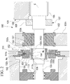
FIG. 2 is a sectional view illustrating a configuration of a main portion of the geared compressor according to the embodiment of the invention. -
FIG. 3 is a view illustrating an overall configuration of a modification example of the geared compressor according to the embodiment of the invention. -
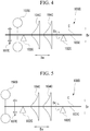
FIG. 4 is a view illustrating an overall configuration of a centrifugal compressor which is a modification example of a rotary machine according to the embodiment of the invention. -
FIG. 5 is a view illustrating an overall configuration of another modification example of the centrifugal compressor which is the modification example of the rotary machine according to the embodiment of the invention. - Hereinafter, a rotary machine of the present invention will be described with reference to the drawings.
- As illustrated in
FIGS. 1 and2 , the rotary machine of the present embodiment is a gearedcompressor 100. The gearedcompressor 100 includes a casing 101 (refer toFIG. 2 ), aradial bearing 102, a rotatingshaft 103, an impeller 104 (refer toFIG. 1 ), apinion gear 105, adriving gear 106, a thrust bearing 107, and anadditional mass 150. - In addition, hereinafter, the direction in which a center axis C of the rotating
shaft 103 extends is defined as a center axis direction Da. A radial direction of the rotatingshaft 103 with reference to the center axis C is simply defined as a radial direction Dr. In addition, a direction around the rotatingshaft 103 around the center axis C is defined as a circumferential direction Dc. - The casing 101 (refer to
FIG. 2 ) forms an outer shell of the gearedcompressor 100. - A pair of the
radial bearings 102 is provided in thecasing 101 at intervals in the center axis direction Da of the rotatingshaft 103. The radial bearing 102 rotatably supports the rotatingshaft 103 around the center axis C. In other words, theradial bearing 102 supports a load that acts in the radial direction Dr with respect to the rotating shaft. Theradial bearing 102 is held by abearing holding unit 101h formed integrally with thecasing 101. - The rotating
shaft 103 is made rotatable around the center axis C by a rotation driving force input from the outside. The rotatingshaft 103 is rotatably supported by the pair ofradial bearings 102 around the center axis C thereof. Bothend portions shaft 103 protrude to both sides in the center axis direction Da from the pair ofradial bearings 102. - A pinion gear (driven gear) 105 is fixed to the rotating
shaft 103 between the pair ofradial bearings 102. In other words, thepinion gear 105 is disposed on the inside of the pair ofradial bearings 102 in the center axis direction Da. Thepinion gear 105 meshes with thedriving gear 106. Therefore, the rotation of thedriving gear 106 is transmitted to thepinion gear 105. - The
driving gear 106 is rotationally driven by an external driving source. Thedriving gear 106 is set to have a larger outer diameter than that of thepinion gear 105. Therefore, a rotational speed of the rotatingshaft 103 having thepinion gear 105 is higher than the rotational speed of thedriving gear 106. - The
pinion gear 105 and thedriving gear 106 configure a speedincrease transmission unit 120 that increases the rotational speed of thedriving gear 106 by the external driving source via thepinion gear 105 and transmits the rotational speed to the rotatingshaft 103. - In addition, in the rotating
shaft 103, the thrust bearing 107 is provided at a position separated from thepinion gear 105 in the center axis direction Da. The thrust bearing 107 is disposed on the inside of the pair ofradial bearings 102 in the center axis direction Da. Thethrust bearing 107 supports a load that acts in the center axis direction Da with respect to therotating shaft 103 via a disc-shapedthrust collar 108 which projects the outer side of therotating shaft 103 in the radial direction Dr. Therefore, thethrust bearing 107 restricts the movement of therotating shaft 103 in the center axis direction Da. - As illustrated in
FIG. 1 , theimpeller 104 is fixed to therotating shaft 103 at a position separated from theradial bearing 102 in the center axis direction Da. Theimpeller 104 rotates integrally with therotating shaft 103. Theimpeller 104 of the present embodiment is fixed to therotating shaft 103 on the outer side of the pair ofradial bearings 102 in the center axis direction Da. Specifically, theimpeller 104 is provided at both theend portions rotating shaft 103. Each of theimpellers 104 is a bladed wheel having a plurality of blades in the circumferential direction Dc. - On the outer side of each of the
impellers 104 in the radial direction Dr, thecasing 101 is provided so as to cover theimpeller 104 while opposing the inner circumferential surface. Thecasing 101 has an intake air passage (not illustrated) for taking air as a working fluid by communicating with the outside, and a spiral exhaust air passage (not illustrated) formed on the outer side in the radial direction Dr of theimpeller 104. - The
impeller 104 rotates integrally with therotating shaft 103, and accordingly feeds the air taken in from the intake air passage (not illustrated) on the inside in the radial direction Dr to the exhaust air passage (not illustrated) on the outer side in the radial direction Dr. High-pressure air is supplied to an external device (not illustrated) through the exhaust air passage (not illustrated), and is used for various purposes. - With the
impeller 104, the gearedcompressor 100 configures a pair ofcentrifugal compression units 130 disposed on both sides that interpose the speedincrease transmission unit 120 therebetween. The pair ofcentrifugal compression units 130 includes a first-stagecentrifugal compression unit 130A disposed on a first side interposing the speedincrease transmission unit 120 and a second-stagecentrifugal compression unit 130B disposed on a second side interposing the speedincrease transmission unit 120. In other words, the gearedcompressor 100 is configured as a single-shift two-stage compressor. - In the geared
compressor 100, the fluid compressed by the first-stagecentrifugal compression unit 130A subsequently flows into the second-stagecentrifugal compression unit 130B. In a course of flowing through the second-stagecentrifugal compression unit 130B, the fluid is further compressed into a high-pressure fluid. - As illustrated in
FIG. 2 , agas seal member 113 is provided in thecasing 101 between thecentrifugal compression unit 130 and the speedincrease transmission unit 120. Specifically, thegas seal member 113 is disposed between theimpeller 104 and theradial bearing 102 in the center axis direction Da. Thegas seal member 113 is annular and fixed to the inner circumferential surface of thecasing 101. Alabyrinth seal portion 113s is formed on the inner circumferential surface of thegas seal member 113. Thelabyrinth seal portion 113s is brought into sliding contact with the outer circumferential surface of therotating shaft 103, and accordingly reduces the leakage of the air from thecentrifugal compression unit 130 side to the speedincrease transmission unit 120 side. - As illustrated in
FIG. 1 , theadditional mass 150 is fixed to therotating shaft 103 at a position separated from theradial bearing 102, theimpeller 104, and the thrust bearing 107 in the center axis direction Da. Theadditional mass 150 applies a load to the entire circumference of therotating shaft 103. Theadditional mass 150 has a mass capable of moving the position of the amplitude increase region where the amplitude of therotating shaft 103 in the radial direction Dr starts to increase. The mass of theadditional mass 150 is determined in accordance with the mass of therotating shaft 103 and theimpeller 104 or the disposition of theimpeller 104 with respect to therotating shaft 103. Here, the amplitude increase region is a region that serves as a base point when the amplitude in the radial direction Dr increases in a two-dimensional curve shape in therotating shaft 103. - A pair of
additional mass 150 of the present embodiment is provided on the outer side of the pair ofradial bearings 102 in the center axis direction Da. Specifically, theadditional mass 150 is provided between theradial bearing 102 and theimpeller 104. Theadditional mass 150 is provided at a position closer to theradial bearing 102 than theimpeller 104 in the center axis direction Da with respect to therotating shaft 103 in which theimpeller 104 is provided in theend portion 103a. Further, specifically, theadditional mass 150 is disposed between theradial bearing 102 and thegas seal member 113. Accordingly, theadditional mass 150 moves the position of the amplitude increase region of therotating shaft 103 to the inside in the center axis direction Da with respect to the position where the pair ofradial bearings 102 is provided. - As illustrated in
FIG. 2 , theadditional mass 150 has a cylindrical shape as a whole. Theadditional mass 150 is fixed in a state where therotating shaft 103 is inserted thereinto. Theadditional mass 150 equally applies the load to the entire circumference of therotating shaft 103. - The
additional mass 150 integrally includes abase portion 151 to which the outer circumferential surface and the inner circumferential surface of therotating shaft 103 are fixed, aweight portion 152 disposed on the outer side of thebase portion 151 in the radial direction Dr, and aconnection portion 153 that connects thebase portion 151 and theweight portion 152 to each other. - The
base portion 151 has a cylindrical shape that extends in the center axis direction Da of therotating shaft 103. Thebase portion 151 has an innercircumferential groove 154 recessed from the inner circumferential surface toward the outer side in the radial direction Dr and a pair ofcontact portions 155 which is in contact with the outer circumferential surface of therotating shaft 103. - The inner
circumferential groove 154 is recessed on the outer side in the radial direction Dr at the center part in the center axial direction Da on the inner circumferential surface. The innercircumferential groove 154 is continuously formed in the circumferential direction Dc over the entire circumference of the inner circumferential surface. The innercircumferential groove 154 is formed only at the center part in the center axial direction Da on the inner circumferential surface of thebase portion 151. - The
contact portion 155 forms the inner circumferential surface of thebase portion 151. Thecontact portion 155 is formed on both sides in the center axis direction Da with respect to the innercircumferential groove 154. By thecontact portion 155, thebase portion 151 is shrunk-fit over the entire circumference with respect to the outer circumferential surface of therotating shaft 103. - Here, the
rotating shaft 103 is formed with a radially expandedportion 103k which is radially expanded to the outer side in the radial direction Dr in regions opposing the innercircumferential groove 154 and thecontact portions 155 on both sides thereof. In theadditional mass 150, thecontact portion 155 is fixed to the outer circumferential surface of therotating shaft 103 by press-fitting the radially expandedportion 103k on the inside of thecontact portion 155. - The
contact portion 155 of the present embodiment includes afirst contact portion 155a on theimpeller 104 side in the center axis direction Da (outer side in the center axis direction Da) and asecond contact portion 155b on theradial bearing 102 side in the center axis direction Da (inside in the center axis direction Da). - In the
base portion 151, an innercircumferential flange portion 156 that protrudes to the inside of thefirst contact portion 155a in the radial direction Dr is integrally formed at the end portion on theimpeller 104 side. The innercircumferential flange portion 156 restrains the movement of theadditional mass 150 to theradial bearing 102 side in the center axis direction Da by abutting against the radially expandedportion 103k of therotating shaft 103 from the center axis direction Da. - The
weight portion 152 is formed on the outer side in the radial direction Dr with respect to the innercircumferential groove 154 of thebase portion 151 and thecontact portions 155 on both sides thereof. Theweight portion 152 has a cylindrical shape that extends in the center axis direction Da of therotating shaft 103. Theweight portion 152 has a larger mass than that of thebase portion 151. Theweight portion 152 is formed to be longer in the radial direction Dr than thebase portion 151. Theweight portion 152 is formed to be shorter in the center axis direction Da than thebase portion 151. Theweight portion 152 is disposed at a position where a center Wc in the center axis direction Da overlaps a center Mc in the center axial direction Da of the innercircumferential groove 154. - A
seal member 114 fixed to the inner circumferential surface of thecasing 101 is provided on the outer side of theweight portion 152 in the radial direction Dr. Theseal member 114 has alabyrinth seal portion 114s on the inner circumferential surface thereof and thelabyrinth seal portion 114s is in sliding contact with the outer circumferential surface of theweight portion 152. - The
connection portion 153 has a smaller mass than that of thebase portion 151 and theweight portion 152. Theconnection portion 153 is formed to be shorter in the radial direction Dr than thebase portion 151 and theweight portion 152. Theconnection portion 153 is formed to be shorter in the center axis direction Da than thebase portion 151 and theweight portion 152. The length of theconnection portion 153 in the center axis direction Da is formed to be shorter than the length of the innercircumferential groove 154 in the center axial direction Da. Theconnection portion 153 is formed at a position where the position in the center axis direction Da overlaps with the innercircumferential groove 154. Theconnection portion 153 is formed at a position separated from thefirst contact portion 155a and thesecond contact portion 155b. In other words, theconnection portion 153 is disposed so as to be interposed by thefirst contact portion 155a and thesecond contact portion 155b in the center axis direction Da. - The
connection portion 153 of the present embodiment is disposed at a position along the center Wc of theweight portion 152 and the center Mc of the innercircumferential groove 154. Theconnection portion 153 is formed by continuously formingslits 157 that are respectively recessed to the inside in the center axis direction Da from the side surfaces 152s on both sides of theweight portion 152 in the center axis direction Da over the entire circumference in the circumferential direction Dc. - According to the geared
compressor 100 of the above-described embodiment, theadditional mass 150 moves the position of the amplitude increase region of therotating shaft 103 near the position where theradial bearing 102 is disposed. Therefore, the amplitude of therotating shaft 103 at the position where theradial bearing 102 is disposed increases. Accordingly, the load in the radial direction Dr from therotating shaft 103 to theradial bearing 102 increases, and therotating shaft 103 can be supported by theradial bearing 102 so as to effectively suppress the vibration of therotating shaft 103. Therefore, even in a state where the position of theradial bearing 102 or the position of theimpeller 104 is fixed, the vibration of therotating shaft 103 is suppressed. Accordingly, regardless of theradial bearing 102 and theimpeller 104, the vibration of therotating shaft 103 can be suppressed. - In addition, when the
impeller 104 is provided in the end portion of therotating shaft 103 that protrudes to the outer side of the pair ofradial bearings 102, the vibration of therotating shaft 103 on the outer side of theradial bearing 102 in the center axis direction Da is likely to increase. However, theadditional mass 150 is provided further on theradial bearing 102 side than theend portion 103a of therotating shaft 103 provided with theimpeller 104. Therefore, theadditional mass 150 moves the amplitude increase region of therotating shaft 103 in the vicinity of theradial bearing 102 or on the inside of theradial bearing 102 in the center axis direction Da. As a result, it is possible to effectively suppress the vicinity of the amplitude increase region of therotating shaft 103 by theradial bearing 102. Accordingly, even in a state where the position of theradial bearing 102 or the position of theimpeller 104 is fixed, the vibration of therotating shaft 103 can be effectively suppressed. - Further, the
additional mass 150 connects thebase portion 151 and theweight portion 152 to each other by theconnection portion 153 that extends in the radial direction. Therefore, when theadditional mass 150 integrally rotates with therotating shaft 103, a centrifugal force F generated by theweight portion 152 is transmitted to thebase portion 151 via theconnection portion 153. In particular, theconnection portion 153 is disposed at the center Wc of theweight portion 152 and the center Mc of the innercircumferential groove 154. Therefore, the centrifugal force F that acts on theweight portion 152 transmitted to thebase portion 151 acts in the vicinity of the center Mc of the innercircumferential groove 154, and the vicinity of the center portion of thebase portion 151 in the center axis direction Da is pulled to the outer side in the radial direction Dr. As a result, a load is generated in thebase portion 151 so that the innercircumferential groove 154 swells, and thefirst contact portion 155a and thesecond contact portion 155b are respectively pressed against the radially expandedportion 103k of therotating shaft 103. Accordingly, a frictional force generated between thefirst contact portion 155a and thesecond contact portion 155b and therotating shaft 103 increases, and theadditional mass 150 is firmly fixed to therotating shaft 103. - Further, the position of the
connection portion 153 in the center axis direction Da is separated from each of thefirst contact portion 155a and thesecond contact portion 155b. Therefore, it is possible to suppress the centrifugal force F generated by theweight portion 152 from being partially pressed against therotating shaft 103 only on one side of thefirst contact portion 155a and thesecond contact portion 155b. Therefore, it is possible to prevent a fixing force of thefirst contact portion 155a and thesecond contact portion 155b on the both sides in the center axis direction Da of the innercircumferential groove 154 with respect to therotating shaft 103 from varying. - Further, the width of the
connection portion 153 in the center axis direction Da is smaller than that of theweight portion 152. According to such a configuration, when the centrifugal force F generated by theweight portion 152 is intensively transmitted to a region connected to theconnection portion 153 of thebase portion 151. Accordingly, it is possible to effectively use the centrifugal force F generated by theweight portion 152, and to press thefirst contact portion 155a and thesecond contact portion 155b against the outer circumferential surface of therotating shaft 103. As a result, theadditional mass 150 is firmly fixed to therotating shaft 103. - In the present embodiment, the
additional mass 150 is disposed on both outer sides of the pair ofradial bearings 102, but the present invention is not limited thereto. For example, as illustrated inFIG. 3 , theadditional mass 150 may be provided on the inside of the pair ofradial bearings 102 and on the outer side in the center axis direction Da with respect to thepinion gear 105. - Above, although the embodiment of the present invention has been described in detail with reference to the drawings, the respective configurations and combinations thereof in the embodiment are merely examples, and additions, omissions, substitutions, and other changes of configurations are possible within the scope not departing from the gist of the present invention. In addition, the present invention is not limited by the embodiment, but is limited only by the claims.
- For example, in the above-described embodiment, as an aspect of the geared
compressor 100, a so-called single-shift two-stage configuration is described as an example. However, the aspect of the gearedcompressor 100 is not limited thereto, and a two-shift four-stage configuration or a configuration having more shifts and more stages may be provided in accordance with design and specifications. Regardless of the configuration, thecentrifugal compression unit 130 of each stage can obtain the same operational effect as described in the above-described embodiment. - Further, the rotary machine of the present invention is not limited to the geared
compressor 100. The rotary machine can also be applied to a single-shift multistage centrifugal compressor of a type in which therotating shaft 103 is directly rotationally driven by the external driving source. - For example, as illustrated in
FIG. 4 , a single-shift multistage centrifugal compressor (rotary machine) 100C of a type in which arotating shaft 103C is directly rotationally driven by an external driving source includes therotating shaft 103C that is rotatably supported by a pair ofradial bearings 102C, a plurality ofimpellers 104C provided in therotating shaft 103C between the one pair ofradial bearings 102C, and athrust bearing 107C for restraining movement of therotating shaft 103C in the center axis direction Da. - In the single-shift multistage
centrifugal compressor 100C, theadditional mass 150C similar to the above-described embodiment is provided in therotating shaft 103C at a position on the outer side of the pair ofradial bearings 102C, that is, at a position on the inside of the thrust bearing 107C in the center axis direction Da. - In such a configuration, by providing the
additional mass 150C, it is possible to move the position of the amplitude increase region of therotating shaft 103C near the position where theradial bearing 102C is disposed from the position where theimpeller 104C is disposed. Accordingly, the load in the radial direction Dr from therotating shaft 103C to theradial bearing 102C is generated, and therotating shaft 103C can be supported by theradial bearing 102C so as to effectively suppress the vibration of therotating shaft 103C. Therefore, it is possible to effectively suppress the vibration of therotating shaft 103C. - In addition, a single-shift multistage centrifugal compressor (rotary machine) 100D illustrated in
FIG. 5 includes therotating shaft 103C that is rotatably supported by the pair ofradial bearings 102C, the plurality ofimpellers 104C provided in therotating shaft 103C between the pair ofradial bearings 102C, and the thrust bearing 107C for restraining movement of therotating shaft 103C in the center axis direction Da. - In the single-shift multistage
centrifugal compressor 100D, anadditional mass 150D similar to that in the above-described embodiment is provided in therotating shaft 103C at a position on the outer side of the pair ofradial bearings 102C, that is, at a position on the outer side of the thrust bearing 107C in the center axis direction Da. - Even with such a configuration, similar to the above-described embodiment, it is possible to effectively suppress the vibration of the
rotating shaft 103C. - According to the above-described rotary machine, regardless of the impeller and the radial bearing, it is possible to suppress the vibration of the rotating shaft.
-
- 100
- Geared compressor (rotary machine)
- 100C, 100D
- Single-shift multistage centrifugal compressor (rotary machine)
- 101
- Casing
- 101h
- Bearing holding unit
- 102, 102C
- Radial bearing
- 103, 103C
- Rotating shaft
- 103a
- End portion
- 103k
- Radially expanded portion
- 104, 104C
- Impeller
- 105
- Pinion gear (driven gear)
- 106
- Driving gear
- 107, 107C
- Thrust bearing
- 108
- Thrust collar
- 113
- Gas seal member
- 113s
- Labyrinth seal portion
- 114
- Seal member
- 114s
- Labyrinth seal portion
- 120
- Speed increase transmission unit
- 130
- Centrifugal compression unit
- 130A, 130B
- Centrifugal compression unit
- 150, 150C, 150D
- Additional mass
- 151
- Base portion
- 151a
- Center portion
- 152
- Weight portion
- 152s
- Side surface
- 153
- Connection portion
- 154
- Inner circumferential groove
- 155
- Contact portion
- 155a
- First contact portion
- 155b
- Second contact portion
- 156
- inner circumferential flange portion
- 157
- Slit
- C
- Center axis
- F
- Centrifugal force
- Mc
- Center
- Wc
- Center
Claims (7)
- A rotary machine comprising:a rotating shaft that is configured to rotate around a center axis by a rotation driving force input from an outside;a pair of radial bearings for rotatably supporting the rotating shaft around the center axis;a thrust bearing for restraining movement of the rotating shaft in a center axis direction;impellers fixed to the rotating shaft at a position separated from the radial bearing in the center axis direction, and integrally rotating with the rotating shaft; andadditional masses fixed to the rotating shaft at positions separated from both the radial bearings and the impellers in the center axis direction, and applying a load to an entire circumference of the rotating shaft so as to move positions of amplitude increase regions where an amplitude in a radial direction of the rotating shaft starts to increase.
- The rotary machine according to Claim 1,
wherein the impellers are fixed to the rotating shaft on an outer side of the pair of the radial bearings in the center axis direction, and
wherein the additional mass is fixed to the rotating shaft between the impeller in the center axis direction and the radial bearing. - The rotary machine according to Claim 1 or 2,
wherein the additional mass includesa base portion fixed to an outer circumferential surface of the rotating shaft,a weight portion provided on an outer side in the radial direction with respect to the base portion, anda connection portion that connects the base portion and the weight portion to each other,wherein the base portion includesan inner circumferential groove recessed from a center part in the center axis direction on an inner circumferential surface of the base portion which is in contact with an outer circumferential surface of the rotating shaft, anda pair of contact portions that is in contact with the outer circumferential surface of the rotating shaft and is formed on both sides in the center axis direction with respect to the inner circumferential groove, andwherein the connection portion is formed at a position where the position in the center axis direction overlaps the inner circumferential groove. - The rotary machine according to Claim 3,
wherein the connection portion is formed so that the position in the center axis direction is separated from the pair of the contact portions. - The rotary machine according to Claim 3 or 4,
wherein a length of the connection portion is shorter than that of the weight portion in the center axis direction. - The rotary machine according to any one of Claims 1 to 5,
wherein the rotary machine is a geared compressor includinga driving gear configured to be rotationally driven by a driving source, anda driven gear to which rotation of the driving gear is transmitted and which is fixed to the rotating shaft, andwherein the driven gear is disposed on an inside of the pair of the radial bearings in the center axis direction. - The rotary machine according to any one of Claims 1 to 5,
wherein the rotary machine is a single-shift multistage centrifugal compressor in which a plurality of the impellers is disposed on an inside of the pair of the radial bearings in the center axis direction.
Applications Claiming Priority (1)
| Application Number | Priority Date | Filing Date | Title |
|---|---|---|---|
| PCT/JP2016/083072 WO2018087808A1 (en) | 2016-11-08 | 2016-11-08 | Rotary machine |
Publications (3)
| Publication Number | Publication Date |
|---|---|
| EP3521632A1 true EP3521632A1 (en) | 2019-08-07 |
| EP3521632A4 EP3521632A4 (en) | 2019-08-21 |
| EP3521632B1 EP3521632B1 (en) | 2020-08-26 |
Family
ID=62109666
Family Applications (1)
| Application Number | Title | Priority Date | Filing Date |
|---|---|---|---|
| EP16921178.6A Active EP3521632B1 (en) | 2016-11-08 | 2016-11-08 | Rotary machine |
Country Status (4)
| Country | Link |
|---|---|
| US (1) | US11143206B2 (en) |
| EP (1) | EP3521632B1 (en) |
| JP (1) | JP6697094B2 (en) |
| WO (1) | WO2018087808A1 (en) |
Families Citing this family (2)
| Publication number | Priority date | Publication date | Assignee | Title |
|---|---|---|---|---|
| US11560900B2 (en) | 2020-06-09 | 2023-01-24 | Emerson Climate Technologies, Inc. | Compressor driveshaft assembly and compressor including same |
| JP7531380B2 (en) * | 2020-12-14 | 2024-08-09 | 三菱重工コンプレッサ株式会社 | Rotating Machinery |
Family Cites Families (18)
| Publication number | Priority date | Publication date | Assignee | Title |
|---|---|---|---|---|
| US4044628A (en) * | 1976-03-24 | 1977-08-30 | U.S. Manufacturing Corporation | Torsional damper |
| US4743174A (en) * | 1985-10-18 | 1988-05-10 | Hitachi, Ltd. | Centrifugal compressor |
| JPS6322301U (en) | 1986-07-29 | 1988-02-15 | ||
| JPS6363501U (en) | 1986-10-16 | 1988-04-26 | ||
| JPH075201Y2 (en) * | 1987-07-08 | 1995-02-08 | 石川島播磨重工業株式会社 | Turbine shaft structure |
| JPH01298927A (en) | 1988-05-25 | 1989-12-01 | Toshiba Corp | Rotor for rotary electric machine |
| EP0409202B1 (en) * | 1989-07-20 | 1995-03-01 | Tokai Rubber Industries, Ltd. | Dynamic damper |
| US6043580A (en) * | 1995-10-06 | 2000-03-28 | Sulzer Turbo Ag | Rotodynamic machine for the forwarding of a fluid |
| EP1069313B1 (en) * | 1999-07-16 | 2005-09-14 | Man Turbo Ag | Turbo compressor |
| JP2001349379A (en) * | 2000-06-09 | 2001-12-21 | Tokai Rubber Ind Ltd | Dynamic damper |
| EP1293657A1 (en) | 2001-09-17 | 2003-03-19 | ABB Turbo Systems AG | Turbocharger with torsion damper |
| JP2003139196A (en) * | 2001-10-31 | 2003-05-14 | Tokai Rubber Ind Ltd | Dynamic damper |
| JP4029665B2 (en) * | 2002-05-27 | 2008-01-09 | 東海ゴム工業株式会社 | Dynamic damper |
| WO2007108234A1 (en) * | 2006-03-23 | 2007-09-27 | Ihi Corporation | High-speed rotating shaft for supercharger |
| JP4636441B2 (en) * | 2006-04-27 | 2011-02-23 | 東海ゴム工業株式会社 | Cylindrical dynamic damper |
| US8753069B2 (en) * | 2010-08-30 | 2014-06-17 | Dresser-Rand Company | Eddy current damper and method |
| US9624936B2 (en) * | 2012-05-16 | 2017-04-18 | Compressor Controls Corporation | Turbocompressor antisurge control by vibration monitoring |
| KR102357883B1 (en) | 2014-12-11 | 2022-02-03 | 두산중공업 주식회사 | Damper unit for shaft |
-
2016
- 2016-11-08 US US16/348,003 patent/US11143206B2/en active Active
- 2016-11-08 JP JP2018549654A patent/JP6697094B2/en active Active
- 2016-11-08 WO PCT/JP2016/083072 patent/WO2018087808A1/en not_active Ceased
- 2016-11-08 EP EP16921178.6A patent/EP3521632B1/en active Active
Also Published As
| Publication number | Publication date |
|---|---|
| EP3521632B1 (en) | 2020-08-26 |
| JPWO2018087808A1 (en) | 2019-09-26 |
| EP3521632A4 (en) | 2019-08-21 |
| WO2018087808A1 (en) | 2018-05-17 |
| JP6697094B2 (en) | 2020-05-20 |
| US11143206B2 (en) | 2021-10-12 |
| US20190285091A1 (en) | 2019-09-19 |
Similar Documents
| Publication | Publication Date | Title |
|---|---|---|
| EP2693017A1 (en) | Turbocharger and method for manufacturing floating bush | |
| JP2006125387A5 (en) | ||
| US9599152B2 (en) | Compact squeeze film damper bearing | |
| EP3256707B1 (en) | Bearings for a turbocharger | |
| US20150016958A1 (en) | Vacuum pump | |
| WO2015125246A1 (en) | Rotating machine system | |
| JP2013002466A (en) | Thrust bearing structure and supercharger | |
| EP3521632B1 (en) | Rotary machine | |
| EP4036415A1 (en) | Geared compressor and method of designing geared compressor | |
| US10415644B2 (en) | Rotary machine | |
| JP5023903B2 (en) | Centrifugal compressor | |
| US20200325906A1 (en) | Rotary machine with improved shaft | |
| JP5527088B2 (en) | Thrust load transmission mechanism of gear unit | |
| JP2009287560A (en) | Thrust bearing seal for turbocharger | |
| JP7367351B2 (en) | Multistage planetary roller power transmission device | |
| JP5789210B2 (en) | Centrifugal compressor assembly method and centrifugal compressor | |
| JP5876753B2 (en) | Centrifugal compressor | |
| US11280349B2 (en) | Impeller and rotary machine | |
| US20120275923A1 (en) | Rotor for a turbo-machine | |
| KR20170068160A (en) | High-speed bearing device | |
| CN114258460A (en) | Pump device comprising a radial bearing | |
| JP5435215B2 (en) | Bearing device | |
| JP2015116111A (en) | Rotation system | |
| EP3869065A1 (en) | Rotary machine | |
| JP6713363B2 (en) | transmission |
Legal Events
| Date | Code | Title | Description |
|---|---|---|---|
| STAA | Information on the status of an ep patent application or granted ep patent |
Free format text: STATUS: THE INTERNATIONAL PUBLICATION HAS BEEN MADE |
|
| PUAI | Public reference made under article 153(3) epc to a published international application that has entered the european phase |
Free format text: ORIGINAL CODE: 0009012 |
|
| STAA | Information on the status of an ep patent application or granted ep patent |
Free format text: STATUS: REQUEST FOR EXAMINATION WAS MADE |
|
| 17P | Request for examination filed |
Effective date: 20190502 |
|
| AK | Designated contracting states |
Kind code of ref document: A1 Designated state(s): AL AT BE BG CH CY CZ DE DK EE ES FI FR GB GR HR HU IE IS IT LI LT LU LV MC MK MT NL NO PL PT RO RS SE SI SK SM TR |
|
| AX | Request for extension of the european patent |
Extension state: BA ME |
|
| A4 | Supplementary search report drawn up and despatched |
Effective date: 20190722 |
|
| RIC1 | Information provided on ipc code assigned before grant |
Ipc: F01D 5/02 20060101ALI20190716BHEP Ipc: F01D 5/04 20060101ALI20190716BHEP Ipc: F04D 29/66 20060101ALI20190716BHEP Ipc: F04D 29/28 20060101AFI20190716BHEP |
|
| DAV | Request for validation of the european patent (deleted) | ||
| DAX | Request for extension of the european patent (deleted) | ||
| GRAP | Despatch of communication of intention to grant a patent |
Free format text: ORIGINAL CODE: EPIDOSNIGR1 |
|
| STAA | Information on the status of an ep patent application or granted ep patent |
Free format text: STATUS: GRANT OF PATENT IS INTENDED |
|
| INTG | Intention to grant announced |
Effective date: 20200319 |
|
| GRAS | Grant fee paid |
Free format text: ORIGINAL CODE: EPIDOSNIGR3 |
|
| GRAA | (expected) grant |
Free format text: ORIGINAL CODE: 0009210 |
|
| STAA | Information on the status of an ep patent application or granted ep patent |
Free format text: STATUS: THE PATENT HAS BEEN GRANTED |
|
| AK | Designated contracting states |
Kind code of ref document: B1 Designated state(s): AL AT BE BG CH CY CZ DE DK EE ES FI FR GB GR HR HU IE IS IT LI LT LU LV MC MK MT NL NO PL PT RO RS SE SI SK SM TR |
|
| REG | Reference to a national code |
Ref country code: GB Ref legal event code: FG4D |
|
| REG | Reference to a national code |
Ref country code: CH Ref legal event code: EP |
|
| REG | Reference to a national code |
Ref country code: AT Ref legal event code: REF Ref document number: 1306641 Country of ref document: AT Kind code of ref document: T Effective date: 20200915 |
|
| REG | Reference to a national code |
Ref country code: IE Ref legal event code: FG4D |
|
| REG | Reference to a national code |
Ref country code: DE Ref legal event code: R096 Ref document number: 602016043017 Country of ref document: DE |
|
| REG | Reference to a national code |
Ref country code: LT Ref legal event code: MG4D |
|
| PG25 | Lapsed in a contracting state [announced via postgrant information from national office to epo] |
Ref country code: FI Free format text: LAPSE BECAUSE OF FAILURE TO SUBMIT A TRANSLATION OF THE DESCRIPTION OR TO PAY THE FEE WITHIN THE PRESCRIBED TIME-LIMIT Effective date: 20200826 Ref country code: LT Free format text: LAPSE BECAUSE OF FAILURE TO SUBMIT A TRANSLATION OF THE DESCRIPTION OR TO PAY THE FEE WITHIN THE PRESCRIBED TIME-LIMIT Effective date: 20200826 Ref country code: HR Free format text: LAPSE BECAUSE OF FAILURE TO SUBMIT A TRANSLATION OF THE DESCRIPTION OR TO PAY THE FEE WITHIN THE PRESCRIBED TIME-LIMIT Effective date: 20200826 Ref country code: SE Free format text: LAPSE BECAUSE OF FAILURE TO SUBMIT A TRANSLATION OF THE DESCRIPTION OR TO PAY THE FEE WITHIN THE PRESCRIBED TIME-LIMIT Effective date: 20200826 Ref country code: PT Free format text: LAPSE BECAUSE OF FAILURE TO SUBMIT A TRANSLATION OF THE DESCRIPTION OR TO PAY THE FEE WITHIN THE PRESCRIBED TIME-LIMIT Effective date: 20201228 Ref country code: NO Free format text: LAPSE BECAUSE OF FAILURE TO SUBMIT A TRANSLATION OF THE DESCRIPTION OR TO PAY THE FEE WITHIN THE PRESCRIBED TIME-LIMIT Effective date: 20201126 Ref country code: GR Free format text: LAPSE BECAUSE OF FAILURE TO SUBMIT A TRANSLATION OF THE DESCRIPTION OR TO PAY THE FEE WITHIN THE PRESCRIBED TIME-LIMIT Effective date: 20201127 Ref country code: BG Free format text: LAPSE BECAUSE OF FAILURE TO SUBMIT A TRANSLATION OF THE DESCRIPTION OR TO PAY THE FEE WITHIN THE PRESCRIBED TIME-LIMIT Effective date: 20201126 |
|
| REG | Reference to a national code |
Ref country code: NL Ref legal event code: MP Effective date: 20200826 |
|
| REG | Reference to a national code |
Ref country code: AT Ref legal event code: MK05 Ref document number: 1306641 Country of ref document: AT Kind code of ref document: T Effective date: 20200826 |
|
| PG25 | Lapsed in a contracting state [announced via postgrant information from national office to epo] |
Ref country code: PL Free format text: LAPSE BECAUSE OF FAILURE TO SUBMIT A TRANSLATION OF THE DESCRIPTION OR TO PAY THE FEE WITHIN THE PRESCRIBED TIME-LIMIT Effective date: 20200826 Ref country code: NL Free format text: LAPSE BECAUSE OF FAILURE TO SUBMIT A TRANSLATION OF THE DESCRIPTION OR TO PAY THE FEE WITHIN THE PRESCRIBED TIME-LIMIT Effective date: 20200826 Ref country code: LV Free format text: LAPSE BECAUSE OF FAILURE TO SUBMIT A TRANSLATION OF THE DESCRIPTION OR TO PAY THE FEE WITHIN THE PRESCRIBED TIME-LIMIT Effective date: 20200826 Ref country code: RS Free format text: LAPSE BECAUSE OF FAILURE TO SUBMIT A TRANSLATION OF THE DESCRIPTION OR TO PAY THE FEE WITHIN THE PRESCRIBED TIME-LIMIT Effective date: 20200826 Ref country code: IS Free format text: LAPSE BECAUSE OF FAILURE TO SUBMIT A TRANSLATION OF THE DESCRIPTION OR TO PAY THE FEE WITHIN THE PRESCRIBED TIME-LIMIT Effective date: 20201226 |
|
| PG25 | Lapsed in a contracting state [announced via postgrant information from national office to epo] |
Ref country code: CZ Free format text: LAPSE BECAUSE OF FAILURE TO SUBMIT A TRANSLATION OF THE DESCRIPTION OR TO PAY THE FEE WITHIN THE PRESCRIBED TIME-LIMIT Effective date: 20200826 Ref country code: DK Free format text: LAPSE BECAUSE OF FAILURE TO SUBMIT A TRANSLATION OF THE DESCRIPTION OR TO PAY THE FEE WITHIN THE PRESCRIBED TIME-LIMIT Effective date: 20200826 Ref country code: RO Free format text: LAPSE BECAUSE OF FAILURE TO SUBMIT A TRANSLATION OF THE DESCRIPTION OR TO PAY THE FEE WITHIN THE PRESCRIBED TIME-LIMIT Effective date: 20200826 Ref country code: EE Free format text: LAPSE BECAUSE OF FAILURE TO SUBMIT A TRANSLATION OF THE DESCRIPTION OR TO PAY THE FEE WITHIN THE PRESCRIBED TIME-LIMIT Effective date: 20200826 Ref country code: SM Free format text: LAPSE BECAUSE OF FAILURE TO SUBMIT A TRANSLATION OF THE DESCRIPTION OR TO PAY THE FEE WITHIN THE PRESCRIBED TIME-LIMIT Effective date: 20200826 |
|
| REG | Reference to a national code |
Ref country code: DE Ref legal event code: R097 Ref document number: 602016043017 Country of ref document: DE |
|
| PG25 | Lapsed in a contracting state [announced via postgrant information from national office to epo] |
Ref country code: ES Free format text: LAPSE BECAUSE OF FAILURE TO SUBMIT A TRANSLATION OF THE DESCRIPTION OR TO PAY THE FEE WITHIN THE PRESCRIBED TIME-LIMIT Effective date: 20200826 Ref country code: AL Free format text: LAPSE BECAUSE OF FAILURE TO SUBMIT A TRANSLATION OF THE DESCRIPTION OR TO PAY THE FEE WITHIN THE PRESCRIBED TIME-LIMIT Effective date: 20200826 Ref country code: AT Free format text: LAPSE BECAUSE OF FAILURE TO SUBMIT A TRANSLATION OF THE DESCRIPTION OR TO PAY THE FEE WITHIN THE PRESCRIBED TIME-LIMIT Effective date: 20200826 |
|
| PG25 | Lapsed in a contracting state [announced via postgrant information from national office to epo] |
Ref country code: SK Free format text: LAPSE BECAUSE OF FAILURE TO SUBMIT A TRANSLATION OF THE DESCRIPTION OR TO PAY THE FEE WITHIN THE PRESCRIBED TIME-LIMIT Effective date: 20200826 Ref country code: MC Free format text: LAPSE BECAUSE OF FAILURE TO SUBMIT A TRANSLATION OF THE DESCRIPTION OR TO PAY THE FEE WITHIN THE PRESCRIBED TIME-LIMIT Effective date: 20200826 |
|
| REG | Reference to a national code |
Ref country code: CH Ref legal event code: PL |
|
| PLBE | No opposition filed within time limit |
Free format text: ORIGINAL CODE: 0009261 |
|
| STAA | Information on the status of an ep patent application or granted ep patent |
Free format text: STATUS: NO OPPOSITION FILED WITHIN TIME LIMIT |
|
| GBPC | Gb: european patent ceased through non-payment of renewal fee |
Effective date: 20201126 |
|
| PG25 | Lapsed in a contracting state [announced via postgrant information from national office to epo] |
Ref country code: LU Free format text: LAPSE BECAUSE OF NON-PAYMENT OF DUE FEES Effective date: 20201108 |
|
| 26N | No opposition filed |
Effective date: 20210527 |
|
| REG | Reference to a national code |
Ref country code: BE Ref legal event code: MM Effective date: 20201130 |
|
| PG25 | Lapsed in a contracting state [announced via postgrant information from national office to epo] |
Ref country code: CH Free format text: LAPSE BECAUSE OF NON-PAYMENT OF DUE FEES Effective date: 20201130 Ref country code: LI Free format text: LAPSE BECAUSE OF NON-PAYMENT OF DUE FEES Effective date: 20201130 Ref country code: SI Free format text: LAPSE BECAUSE OF FAILURE TO SUBMIT A TRANSLATION OF THE DESCRIPTION OR TO PAY THE FEE WITHIN THE PRESCRIBED TIME-LIMIT Effective date: 20200826 |
|
| PG25 | Lapsed in a contracting state [announced via postgrant information from national office to epo] |
Ref country code: FR Free format text: LAPSE BECAUSE OF NON-PAYMENT OF DUE FEES Effective date: 20201130 Ref country code: IE Free format text: LAPSE BECAUSE OF NON-PAYMENT OF DUE FEES Effective date: 20201108 |
|
| PG25 | Lapsed in a contracting state [announced via postgrant information from national office to epo] |
Ref country code: GB Free format text: LAPSE BECAUSE OF NON-PAYMENT OF DUE FEES Effective date: 20201126 |
|
| PG25 | Lapsed in a contracting state [announced via postgrant information from national office to epo] |
Ref country code: IS Free format text: LAPSE BECAUSE OF FAILURE TO SUBMIT A TRANSLATION OF THE DESCRIPTION OR TO PAY THE FEE WITHIN THE PRESCRIBED TIME-LIMIT Effective date: 20201226 Ref country code: TR Free format text: LAPSE BECAUSE OF FAILURE TO SUBMIT A TRANSLATION OF THE DESCRIPTION OR TO PAY THE FEE WITHIN THE PRESCRIBED TIME-LIMIT Effective date: 20200826 Ref country code: MT Free format text: LAPSE BECAUSE OF FAILURE TO SUBMIT A TRANSLATION OF THE DESCRIPTION OR TO PAY THE FEE WITHIN THE PRESCRIBED TIME-LIMIT Effective date: 20200826 Ref country code: CY Free format text: LAPSE BECAUSE OF FAILURE TO SUBMIT A TRANSLATION OF THE DESCRIPTION OR TO PAY THE FEE WITHIN THE PRESCRIBED TIME-LIMIT Effective date: 20200826 |
|
| PG25 | Lapsed in a contracting state [announced via postgrant information from national office to epo] |
Ref country code: MK Free format text: LAPSE BECAUSE OF FAILURE TO SUBMIT A TRANSLATION OF THE DESCRIPTION OR TO PAY THE FEE WITHIN THE PRESCRIBED TIME-LIMIT Effective date: 20200826 |
|
| PG25 | Lapsed in a contracting state [announced via postgrant information from national office to epo] |
Ref country code: BE Free format text: LAPSE BECAUSE OF NON-PAYMENT OF DUE FEES Effective date: 20201130 |
|
| PGFP | Annual fee paid to national office [announced via postgrant information from national office to epo] |
Ref country code: DE Payment date: 20241001 Year of fee payment: 9 |
|
| PGFP | Annual fee paid to national office [announced via postgrant information from national office to epo] |
Ref country code: IT Payment date: 20241010 Year of fee payment: 9 |