EP3521410A1 - Culturing observing system - Google Patents
Culturing observing system Download PDFInfo
- Publication number
- EP3521410A1 EP3521410A1 EP17855906.8A EP17855906A EP3521410A1 EP 3521410 A1 EP3521410 A1 EP 3521410A1 EP 17855906 A EP17855906 A EP 17855906A EP 3521410 A1 EP3521410 A1 EP 3521410A1
- Authority
- EP
- European Patent Office
- Prior art keywords
- sample
- light
- observation device
- source unit
- illumination light
- Prior art date
- Legal status (The legal status is an assumption and is not a legal conclusion. Google has not performed a legal analysis and makes no representation as to the accuracy of the status listed.)
- Pending
Links
Images










Classifications
-
- G—PHYSICS
- G02—OPTICS
- G02B—OPTICAL ELEMENTS, SYSTEMS OR APPARATUS
- G02B21/00—Microscopes
- G02B21/0004—Microscopes specially adapted for specific applications
- G02B21/0088—Inverse microscopes
-
- C—CHEMISTRY; METALLURGY
- C12—BIOCHEMISTRY; BEER; SPIRITS; WINE; VINEGAR; MICROBIOLOGY; ENZYMOLOGY; MUTATION OR GENETIC ENGINEERING
- C12M—APPARATUS FOR ENZYMOLOGY OR MICROBIOLOGY; APPARATUS FOR CULTURING MICROORGANISMS FOR PRODUCING BIOMASS, FOR GROWING CELLS OR FOR OBTAINING FERMENTATION OR METABOLIC PRODUCTS, i.e. BIOREACTORS OR FERMENTERS
- C12M41/00—Means for regulation, monitoring, measurement or control, e.g. flow regulation
- C12M41/48—Automatic or computerized control
-
- C—CHEMISTRY; METALLURGY
- C12—BIOCHEMISTRY; BEER; SPIRITS; WINE; VINEGAR; MICROBIOLOGY; ENZYMOLOGY; MUTATION OR GENETIC ENGINEERING
- C12M—APPARATUS FOR ENZYMOLOGY OR MICROBIOLOGY; APPARATUS FOR CULTURING MICROORGANISMS FOR PRODUCING BIOMASS, FOR GROWING CELLS OR FOR OBTAINING FERMENTATION OR METABOLIC PRODUCTS, i.e. BIOREACTORS OR FERMENTERS
- C12M1/00—Apparatus for enzymology or microbiology
-
- C—CHEMISTRY; METALLURGY
- C12—BIOCHEMISTRY; BEER; SPIRITS; WINE; VINEGAR; MICROBIOLOGY; ENZYMOLOGY; MUTATION OR GENETIC ENGINEERING
- C12M—APPARATUS FOR ENZYMOLOGY OR MICROBIOLOGY; APPARATUS FOR CULTURING MICROORGANISMS FOR PRODUCING BIOMASS, FOR GROWING CELLS OR FOR OBTAINING FERMENTATION OR METABOLIC PRODUCTS, i.e. BIOREACTORS OR FERMENTERS
- C12M1/00—Apparatus for enzymology or microbiology
- C12M1/34—Measuring or testing with condition measuring or sensing means, e.g. colony counters
-
- C—CHEMISTRY; METALLURGY
- C12—BIOCHEMISTRY; BEER; SPIRITS; WINE; VINEGAR; MICROBIOLOGY; ENZYMOLOGY; MUTATION OR GENETIC ENGINEERING
- C12M—APPARATUS FOR ENZYMOLOGY OR MICROBIOLOGY; APPARATUS FOR CULTURING MICROORGANISMS FOR PRODUCING BIOMASS, FOR GROWING CELLS OR FOR OBTAINING FERMENTATION OR METABOLIC PRODUCTS, i.e. BIOREACTORS OR FERMENTERS
- C12M23/00—Constructional details, e.g. recesses, hinges
- C12M23/22—Transparent or translucent parts
-
- C—CHEMISTRY; METALLURGY
- C12—BIOCHEMISTRY; BEER; SPIRITS; WINE; VINEGAR; MICROBIOLOGY; ENZYMOLOGY; MUTATION OR GENETIC ENGINEERING
- C12M—APPARATUS FOR ENZYMOLOGY OR MICROBIOLOGY; APPARATUS FOR CULTURING MICROORGANISMS FOR PRODUCING BIOMASS, FOR GROWING CELLS OR FOR OBTAINING FERMENTATION OR METABOLIC PRODUCTS, i.e. BIOREACTORS OR FERMENTERS
- C12M41/00—Means for regulation, monitoring, measurement or control, e.g. flow regulation
- C12M41/12—Means for regulation, monitoring, measurement or control, e.g. flow regulation of temperature
- C12M41/14—Incubators; Climatic chambers
-
- G—PHYSICS
- G01—MEASURING; TESTING
- G01N—INVESTIGATING OR ANALYSING MATERIALS BY DETERMINING THEIR CHEMICAL OR PHYSICAL PROPERTIES
- G01N21/00—Investigating or analysing materials by the use of optical means, i.e. using sub-millimetre waves, infrared, visible or ultraviolet light
- G01N21/17—Systems in which incident light is modified in accordance with the properties of the material investigated
-
- G—PHYSICS
- G02—OPTICS
- G02B—OPTICAL ELEMENTS, SYSTEMS OR APPARATUS
- G02B21/00—Microscopes
- G02B21/06—Means for illuminating specimens
-
- G—PHYSICS
- G02—OPTICS
- G02B—OPTICAL ELEMENTS, SYSTEMS OR APPARATUS
- G02B21/00—Microscopes
- G02B21/06—Means for illuminating specimens
- G02B21/08—Condensers
- G02B21/082—Condensers for incident illumination only
- G02B21/084—Condensers for incident illumination only having annular illumination around the objective
-
- G—PHYSICS
- G02—OPTICS
- G02B—OPTICAL ELEMENTS, SYSTEMS OR APPARATUS
- G02B21/00—Microscopes
- G02B21/06—Means for illuminating specimens
- G02B21/08—Condensers
- G02B21/086—Condensers for transillumination only
-
- G—PHYSICS
- G02—OPTICS
- G02B—OPTICAL ELEMENTS, SYSTEMS OR APPARATUS
- G02B21/00—Microscopes
- G02B21/06—Means for illuminating specimens
- G02B21/08—Condensers
- G02B21/12—Condensers affording bright-field illumination
- G02B21/125—Condensers affording bright-field illumination affording both dark- and bright-field illumination
-
- G—PHYSICS
- G02—OPTICS
- G02B—OPTICAL ELEMENTS, SYSTEMS OR APPARATUS
- G02B21/00—Microscopes
- G02B21/36—Microscopes arranged for photographic purposes or projection purposes or digital imaging or video purposes including associated control and data processing arrangements
-
- G—PHYSICS
- G02—OPTICS
- G02B—OPTICAL ELEMENTS, SYSTEMS OR APPARATUS
- G02B21/00—Microscopes
- G02B21/36—Microscopes arranged for photographic purposes or projection purposes or digital imaging or video purposes including associated control and data processing arrangements
- G02B21/362—Mechanical details, e.g. mountings for the camera or image sensor, housings
-
- G—PHYSICS
- G02—OPTICS
- G02B—OPTICAL ELEMENTS, SYSTEMS OR APPARATUS
- G02B26/00—Optical devices or arrangements for the control of light using movable or deformable optical elements
- G02B26/08—Optical devices or arrangements for the control of light using movable or deformable optical elements for controlling the direction of light
-
- G—PHYSICS
- G02—OPTICS
- G02B—OPTICAL ELEMENTS, SYSTEMS OR APPARATUS
- G02B5/00—Optical elements other than lenses
- G02B5/005—Diaphragms
-
- G—PHYSICS
- G16—INFORMATION AND COMMUNICATION TECHNOLOGY [ICT] SPECIALLY ADAPTED FOR SPECIFIC APPLICATION FIELDS
- G16B—BIOINFORMATICS, i.e. INFORMATION AND COMMUNICATION TECHNOLOGY [ICT] SPECIALLY ADAPTED FOR GENETIC OR PROTEIN-RELATED DATA PROCESSING IN COMPUTATIONAL MOLECULAR BIOLOGY
- G16B50/00—ICT programming tools or database systems specially adapted for bioinformatics
- G16B50/30—Data warehousing; Computing architectures
Definitions
- the observation device may be an observation device wherein the light source unit includes a diffusing plate for diffusing illumination light.
Landscapes
- Chemical & Material Sciences (AREA)
- Engineering & Computer Science (AREA)
- Health & Medical Sciences (AREA)
- Physics & Mathematics (AREA)
- Life Sciences & Earth Sciences (AREA)
- Bioinformatics & Cheminformatics (AREA)
- Organic Chemistry (AREA)
- Wood Science & Technology (AREA)
- Zoology (AREA)
- Analytical Chemistry (AREA)
- Biotechnology (AREA)
- General Health & Medical Sciences (AREA)
- General Physics & Mathematics (AREA)
- Biochemistry (AREA)
- Optics & Photonics (AREA)
- General Engineering & Computer Science (AREA)
- Sustainable Development (AREA)
- Microbiology (AREA)
- Biomedical Technology (AREA)
- Genetics & Genomics (AREA)
- Theoretical Computer Science (AREA)
- Computer Hardware Design (AREA)
- Multimedia (AREA)
- Thermal Sciences (AREA)
- Clinical Laboratory Science (AREA)
- Medicinal Chemistry (AREA)
- Biophysics (AREA)
- Databases & Information Systems (AREA)
- Bioinformatics & Computational Biology (AREA)
- Evolutionary Biology (AREA)
- Medical Informatics (AREA)
- Spectroscopy & Molecular Physics (AREA)
- Bioethics (AREA)
- Immunology (AREA)
- Pathology (AREA)
- Microscoopes, Condenser (AREA)
- Apparatus Associated With Microorganisms And Enzymes (AREA)
- Investigating Or Analysing Materials By Optical Means (AREA)
Abstract
Description
- The present invention relates to a culture observation system.
- For conventional cell culturing, the task of taking a culture container out of an incubator, peeling cells off the culture container, and seeding and culturing cells in a new culture container is repeated at predetermined intervals each time cells become confluent (refer to, for example, Patent Literature 1).
- {PTL 1} Japanese Unexamined Patent Application, Publication No.
6-217989 - However, there is a problem in that, during the time period between these tasks, an observer is required to carry out a very burdensome confirmation task of taking out the culture container from the incubator and confirming culture conditions with, for example, a microscope at predetermined time intervals (e.g., once or twice a day).
- The present invention has been conceived in light of the above-described circumstances, and an object thereof is to provide a culture observation device that can reduce the burden of the confirmation task at the time of cell culturing.
- In order to achieve the above-described object, the present invention provides the following solutions.
- One aspect of the present invention is a culture observation system including: an observation device that is disposed in an incubator and that is used to observe a sample in a culture container; a station server that is disposed outside the incubator and that transmits and receives information to and from the observation device; and a terminal for transmitting and receiving information to and from the station server, wherein the observation device includes: a light source unit for emitting illumination light from below the sample to thereabove, said sample being accommodated in the container formed of an optically transparent material; and an image acquisition optical system for acquiring, below the sample, an image of transmitted light that has passed through the sample as a result of the illumination light emitted from the light source unit being reflected at an inner surface of a top plate of the container disposed above the sample.
- According to this aspect, the illumination light emitted from the light source unit passes through the sample from below the sample to thereabove, is reflected above the sample, and passes through the sample from above the sample to therebelow. An image of transmitted light that has passed through the sample is acquired by the image acquisition optical system disposed below the sample. Because both the light source unit and the image acquisition optical system are disposed below the sample, observation is possible without having to increase the size of the device by acquiring an image of transmitted light without labeling a subject, such as cells. Also, because a transmission unit transmits the acquired image to the outside of the incubator, it is possible to confirm the culture state of the cells in the culture container without opening the door of the incubator and taking out the culture container. By doing so, it is possible to reduce the burden at the time of cell culturing.
- In the above-described aspect, the station server and the terminal may transmit and receive information via a cloud server.
- By doing so, a user can remotely confirm the culture state of the cells in the culture container and can remotely operate the observation device in the incubator.
- In the above-described aspect, transmission and reception of information from the station server to the cloud server may be performed according to each instruction from the terminal. In the above-described aspect, transmission and reception of information from the station server to the cloud server may be automatically performed at predetermined intervals and/or for predetermined image data.
- In the above-described aspect, the image acquisition optical system may include an objective lens for collecting the transmitted light that has passed through the sample, and the light source unit may emit illumination light from radially outward of the objective lens to above the sample.
- By doing so, the illumination light emitted towards an area above the sample from the light source unit that is disposed radially outwardly of the objective lens disposed below the sample is reflected above the sample and is incident obliquely downward on the sample relative to the optical axis of the objective lens, whereby an image of the transmitted light that has passed through the sample is acquired by the image acquisition optical system. Light and dark areas can be formed on an image of the sample by appropriately setting the angle of incidence on the sample, thereby making it possible to acquire an easy-to-see image even for a transparent subject, such as cells.
- In the above-described aspect, the light source unit may be capable of independently emitting illumination light from different positions in the radial direction of the objective lens.
- By doing so, the angle of incidence, on the sample, of reflection light reflected by the same reflecting surface disposed above the sample can be changed by making radial positions of illumination light emitted from the light source unit different. More specifically, reflection light of light emitted from a nearby position in the radial direction of the objective lens is incident on the sample at a small angle relative to the optical axis, whereas reflection light of illumination light emitted from a distant position in the radial direction of the objective lens is incident on the sample at a large angle relative to the optical axis. By doing so, bright-field illumination with less illumination unevenness can be achieved in the case of an incidence angle smaller than the capturing angle of the objective lens, dark-field illumination with emphasized microstructures can be achieved in the case of an incidence angle larger than the capturing angle of the objective lens, and furthermore, oblique illumination that allows the sample to appear stereoscopic can be achieved in the case of an incidence angle equivalent to the capturing angle of the objective lens.
- In the above-described aspect, the light source unit may be capable of simultaneously emitting illumination light from different positions in the circumferential direction of the objective lens.
- By doing so, illumination light is simultaneously radiated from a plurality of positions in the circumferential direction of the objective lens, thus making it possible to reduce illumination unevenness.
- In the above-described aspect, the light source unit may include a plurality of light sources that are arrayed around the objective lens and that can be lit up independently.
- By doing so, the circumferential-direction position of illumination light can be determined by lighting up any of the plurality of light sources. Also, an image of the sample irradiated from different directions can be acquired by switching the circumferential-direction position of the light source to be lit up. In particular, in the case of the above-described oblique illumination, images with different shading patterns can be acquired.
- In the above-described aspect, the light source unit may include light sources disposed below the sample and a light-blocking member having an opening that, of the illumination light from the light sources, transmits only illumination light from a particular radial position.
- By doing so, the illumination light from the light sources is blocked by the light-blocking member, thus allowing only illumination light passing through the opening to be reflected above the sample and to be incident on the sample. Therefore, the direction or angle of reflection light that is made incident on the sample can be changed by adjusting the position of the opening in the light-blocking member, without switching the lit-up positions of the light sources.
- In the above-described aspect, the light source unit may include a diffusing plate for diffusing illumination light.
- By doing so, the sample can be irradiated with illumination light that is uniformly diffused by the diffusing plate.
- In the above-described aspect, the sample may be accommodated in a container formed of an optically transparent material, and the illumination light may be reflected at an inner surface of a top plate of the container disposed above the sample.
- By doing so, merely by disposing, above the light source unit and the image acquisition optical system, the container that accommodates the sample therein and that has a top plate, illumination light emitted from the light source unit can be reflected at the inner surface of the top plate of the container and can be radiated on the sample in the container.
- In the above-described aspect, the illumination light may be reflected by a reflecting member disposed above the sample.
- By doing so, in a case where a sample accommodated in a container or a cell culture bag without a top plate, like a petri dish (without a lid), is to be observed, by disposing the reflecting member above the sample, illumination light emitted from the light source unit can be reflected at the reflecting member and can be radiated on the sample in the container.
- In the above-described aspect, the sample may be immersed in a solution, and the illumination light may be reflected at an upper liquid surface of the solution.
- By doing so, in a case where a sample accommodated in a container without a top plate or a container in which no reflecting members can be disposed is to be observed, illumination light emitted from the light source unit can be reflected at the liquid surface of the solution and can be radiated on the sample in the container.
- Another aspect of the present invention is an observation method including: an emission step of emitting illumination light from below a sample to thereabove; a reflection step of reflecting, above the sample, the illumination light emitted in the emission step; a transmission step of causing the illumination light reflected in the reflection step to pass through the sample; and an image acquisition step of acquiring, below the sample, an image of transmitted light that has passed through the sample in the transmission step.
- The present invention affords an advantage in that the burden of a confirmation task at the time of cell culturing can be reduced. Furthermore, the culture state of cells in a culture container can be confirmed without opening the door of an incubator and taking out the culture container, thus suppressing an influence of environmental changes on the sample.
-
- {
Fig. 1 }
Fig. 1 is a longitudinal sectional view depicting an observation device of the present invention. - {
Fig. 2 }
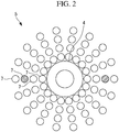
Fig. 2 is a diagram depicting the observation device of the present invention. - {
Fig. 3 }
Fig. 3 is a diagram depicting a modification of the observation device of the present invention. - {
Fig. 4A }
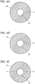
Fig. 4A is a diagram depicting a modification of the observation device of the present invention. - {
Fig. 4B }
Fig. 4B is a diagram depicting a modification of the observation device of the present invention. - {
Fig. 4C }
Fig. 4C is a diagram depicting a modification of the observation device of the present invention. - {
Fig. 5A }
Fig. 5A is a diagram depicting a modification of the observation device of the present invention. - {
Fig. 5B }
Fig. 5B is a diagram depicting a modification of the observation device of the present invention. - {
Fig. 6 }
Fig. 6 is a diagram depicting a modification of the observation device of the present invention. - {
Fig. 7 }
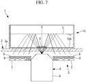
Fig. 7 is a diagram depicting a modification of the observation device of the present invention. - {
Fig. 8 }
Fig. 8 is a diagram depicting a modification of the observation device of the present invention. - {
Fig. 9 }
Fig. 9 is a diagram depicting a modification of the observation device of the present invention. - {
Fig. 10 }
Fig. 10 is a diagram depicting a culture observation system according to a first embodiment of the present invention. - {
Fig. 11 }
Fig. 11 is a diagram depicting a culture observation system according to a second embodiment of the present invention. - {
Fig. 12 }
Fig. 12 is a diagram depicting a modification of the observation device of the present invention. - {
Fig. 13 }
Fig. 13 is a partial longitudinal sectional view depicting an observation device according to a reference embodiment of the present invention. - {
Fig. 14 }
Fig. 14 is a plan view depicting one example of the arrangement of LED light sources in a light source unit of the observation device inFig. 13 . - {
Fig. 15 }
Fig. 15 is a modification of the observation device inFig. 13 in the form of a partial longitudinal sectional view depicting a case where illumination light is restricted by a light-blocking member. - {
Fig. 16A }
Fig. 16A is an example of the light-blocking member inFig. 15 in the form of a plan view depicting a case where the light-blocking member has a single circular opening. - {
Fig. 16B} Fig. 16B is an example of the light-blocking member inFig. 15 in the form of a plan view depicting a case where the radial position of the opening differs from that inFig. 16A {Fig. 16C } -
Fig. 16C is an example of the light-blocking member inFig. 15 in the form of a plan view depicting a case where the light-blocking member has two openings. - {
Fig. 17A }
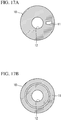
Fig. 17A is another example of the light-blocking member inFig. 15 in the form of a plan view depicting a case where the light-blocking member has a fan-shaped opening. - {
Fig. 17B }
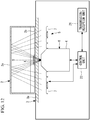
Fig. 17B is another example of the light-blocking member inFig. 15 in the form of a plan view depicting a case where the light-blocking member has a ring-shaped opening. - {
Fig. 18 }
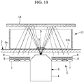
Fig. 18 is a partial longitudinal sectional view depicting another modification of the observation device inFig. 13 . - {
Fig. 19 }
Fig. 19 is a partial longitudinal sectional view depicting another modification of the observation device inFig. 13 . - {
Fig. 20 }
Fig. 20 is a partial longitudinal sectional view depicting another modification of the observation device inFig. 13 . - {
Fig. 21 }
Fig. 21 is a partial longitudinal sectional view depicting another modification of the observation device inFig. 13 . - A
culture observation system 100 according to a first embodiment of the present invention will now be described with reference to the drawings. - As shown in
Fig. 10 , theculture observation system 100 according to this embodiment includes: anobservation device 103 for monitoring a sample (e.g., cells) in aculture container 2 disposed in anincubator 101; astation server 104 that is disposed outside theincubator 101 and that transmits and receives information to and from theobservation device 103 in theincubator 101; and auser terminal 105 for transmitting and receiving information to and from thestation server 104. - As shown in
Fig. 1 , theobservation device 103 according to this embodiment includes: abase 3 for mounting theculture container 2 in which a sample X, such as cells, is accommodated together with a culture solution; and alight source unit 5, animage acquisition unit 6, a transmission/reception unit 21, and acontrol unit 22 that are provided in thebase 3. - The
culture container 2 is, for example, a flask for cell culturing and is formed of an optically transparent material. - The
base 3 is, for example, a housing, and thelight source unit 5, theimage acquisition unit 6, transmission/reception unit 21, and thecontrol unit 22 are provided in the interior of the housing. At least a portion of the top surface of thebase 3 includes a mountingsurface 3a formed of an optically transparent material (e.g., glass), and theculture container 2 is mounted on the mountingsurface 3a. Because the interior of the incubator becomes very humid, thebase 3 preferably has a waterproof structure. - The
image acquisition unit 6 includes: anobjective lens 4 that is disposed in the interior of thebase 3 and below the mountingsurface 3a and that collects light passing through the mountingsurface 3a from thereabove; and an image acquisition optical system for acquiring an image of the light passing through the sample X. - The
light source unit 5 is disposed radially outward of theobjective lens 4 and emits illumination light upward so as to pass through the mountingsurface 3a. - As shown in
Figs. 1 and2 , thelight source unit 5 includes: a plurality of LED light sources (light sources) 7 that are disposed around theobjective lens 4 in a manner spaced apart from one another in the circumferential direction and in the radial direction; a plurality ofcollimating lenses 8 that are disposed in correspondence with the respectiveLED light sources 7 and that convert illumination light generated at the respectiveLED light sources 7 into substantially collimated light; and diffusingplates 9 for diffusing the illumination light collimated by thecollimating lenses 8. - The
light source unit 5 is configured to be capable of lighting up particularLED light sources 7 independently (inFigs. 1 and2 , lit-upLED light sources 7 are indicated in hatching). - More specifically, by lighting up only LED
light sources 7 at different positions in the radial direction of the objective lens, the angles of illumination light that is incident on theobjective lens 4 as shown by solid lines inFig. 1 can be changed as shown by dashed lines, said illumination light having passed upward through the mountingsurface 3a and abottom surface 2b of thecontainer 2, having been reflected at the inner surface of atop plate 2a of thecontainer 2, and having passed obliquely downward through the sample X, thebottom surface 2b of thecontainer 2, and the mountingsurface 3a. - In addition, by lighting up only LED
light sources 7 at specific positions in the circumferential direction of theobjective lens 4, the sample X can be irradiated only in particular directions in the circumferential direction. In addition, as shown inFig. 2 , the sample X can be irradiated with illumination light with reduced illumination unevenness by lighting up theLED light sources 7 disposed in two or more directions in the circumferential direction of theobjective lens 4, particularly in directions axially symmetrical with respect to the optical axis of theobjective lens 4. - The
light source unit 5 may include: a plurality of the LED light sources (light sources) 7 that are disposed around theobjective lens 4 in a manner spaced apart from one another only in the circumferential direction; a plurality ofcollimating lenses 8 that are disposed in correspondence with the respectiveLED light sources 7 and that convert illumination light generated at the respectiveLED light sources 7 into substantially collimated light; and diffusingplates 9 for diffusing the illumination light collimated by thecollimating lenses 8. - Four LED light sources (light sources) 7, four
collimating lenses 8, and four diffusingplates 9 may be provided in a manner spaced apart from one another by 90° in the circumferential direction. - An observation method in which the
observation device 103 according to this embodiment with the above-described structure is used will be described below. - In order to observe the transparent sample X, such as cells, by using the
observation device 103 according to this embodiment, the sample X is accommodated in thecontainer 2, and thecontainer 2 is mounted on the mountingsurface 3a of astage 3 with thebottom surface 2b face down in a state where the sample X is attached to thebottom surface 2b, as shown inFig. 1 . - Then, arbitrary LED
light sources 7 of thelight source unit 5 are turned on in this state to generate illumination light. Illumination light generated in theLED light sources 7 is collimated by thecollimating lenses 8 disposed in correspondence with theLED light sources 7 and is diffused by the diffusingplates 9, and the illumination light in that state passes upward through the mounting surface and thebottom surface 2b of the container 2 (emission step), is reflected at the inner surface of thetop plate 2a of thecontainer 2, and is then radiated obliquely downward onto the sample X (reflection step). - Of the illumination light radiated onto the sample X, transmitted light of the illumination light that has passed through the sample X passes downward through the
bottom surface 2b of thecontainer 2 and the mounting surface and is incident on the objective lens 4 (transmission step). In this case, illumination light is refracted and scattered due to the shape and index of refraction of the sample X or is dimmed due to the transmittance of the sample X and is then collected by theobjective lens 4 in the form of transmitted light carrying information about the sample X, thus causing an image capturing element (not shown in the figure) to acquire an image of the transmitted light (image acquisition step). - In this manner, the
observation device 103 according to this embodiment affords an advantage in that because thelight source unit 5 and the image acquisition optical system including theobjective lens 4 are disposed below the sample X, thelight source unit 5 and the image acquisitionoptical system 6 can be aggregated on only one side of the sample X, thereby making the device thin. There is another advantage in that, even in theobservation device 103 that is made thin in this manner, observation is possible by acquiring an image of transmitted light without labeling a subject, such as cells. - Another advantage is that, as a result of being emitted from radially outward of the
objective lens 4 and being reflected at the inner surface of thetop plate 2a of thecontainer 2, illumination light from thelight source unit 5 is radiated obliquely downward onto the sample X and is collected by theobjective lens 4, and therefore, light and dark areas can be formed on an image of the sample X by appropriately setting the angle of incidence on the sample X, thereby making it possible to acquire an easy-to-see image even for a transparent subject, such as cells. - In addition, because the
light source unit 5 includes the plurality ofLED light sources 7 that are arranged around theobjective lens 4 in the radial direction and that can be lit up independently in this embodiment, the irradiation angles of illumination light incident on the sample X can be changed as shown by dashed lines inFig. 1 by making the radial positions of the lit-upLED light sources 7 different. By doing so, bright-field illumination with less illumination unevenness can be achieved in the case of an incidence angle smaller than the capturing angle of theobjective lens 4, dark-field illumination with emphasized microstructures can be achieved in the case of an incidence angle larger than the capturing angle of theobjective lens 4, and furthermore, oblique illumination that allows the sample X to appear stereoscopic can be achieved in the case of an incidence angle equivalent to the capturing angle of theobjective lens 4. - In addition, because the
light source unit 5 is provided with the plurality ofLED light sources 7 that are arranged around theobjective lens 4 in the circumferential direction thereof and that can be lit up independently in this embodiment, the irradiation directions of illumination light incident on the sample X can be changed by making the circumferential-direction positions of the lit-upLED light sources 7 different. By doing so, the appearance of a formed image of the sample X can be changed by changing the direction of shading of the image. - In addition, as shown in
Fig. 2 , there is an advantage in that a less uneven image of the sample X can be acquired by reducing illumination unevenness by simultaneously lighting up a plurality ofLED light sources 7 at different positions in the circumferential direction, particularly by simultaneously lighting up a plurality ofLED light sources 7 that are axially symmetrically disposed. - In addition, because the diffusing
plates 9 are provided in correspondence with the respectiveLED light sources 7 in this embodiment, illumination light emitted from theLED light sources 7 is uniformly diffused, allowing the sample X to be irradiated with illumination light that has less illumination unevenness and that has more uniform intensity. - Note that although the irradiation angles, the irradiation directions, etc. of illumination light are switched by arranging the plurality of
LED light sources 7 in an array and by lighting up the plurality ofLED light sources 7 independently in this embodiment, instead of this, thelight source unit 5 may include: thelight sources 7 that are disposed around theobjective lens 4; and a light-blockingmember 10 that is disposed above thelight sources 7 and that blocks illumination light from thelight sources 7, as shown inFig. 3 ,Figs. 4A to 4C , andFigs. 5A and 5B . - More specifically, the light-blocking
member 10 includes: an opening 11 formed at a portion in the circumferential direction thereof or at a portion in the radial direction thereof; and atransmission hole 12 for transmitting the light that has been reflected at the inner surface of thetop plate 2a of thecontainer 2 and that has passed through the sample X, thereby making it possible to change the irradiation angles and the irradiation directions of illumination light by adjusting the position of theopening 11 by replacing the light-blockingmember 10. In this case, although thelight source unit 5 may be realized by a light source unit provided with theLED light sources 7, thecollimating lenses 8, and the diffusingplates 9 that are arranged in an array as described above, the function of switching the light-emission positions of illumination light is not necessary, and a light source unit provided with any light sources may be employed as long as the light sources can emit illumination light from an area wider than theopening 11. -
Figs. 4A to 4C show examples wherecircular openings 11 are provided at different radial directions and where different numbers ofopenings 11 are provided.Fig. 5A and Fig. 5B show a fan-shapedopening 11 and a ring-shapedopening 11, respectively. For theopenings 11, openings having any sizes, positions, and shapes can be employed. - Although the sample X is accommodated in the
container 2, such as a cell culture flask, having thetop plate 2a so that illumination light is reflected at the inner surface of thetop plate 2a of thecontainer 2 in this embodiment, the present invention is not limited to this. For example, if the sample X is accommodated in acontainer 13 not having thetop plate 2a, such as a petri dish (without a lid), serving as thecontainer 2, a reflectingmember 14, such as a mirror, may be disposed at a position where the reflectingmember 14 covers the top opening of the petri dish, as shown inFig. 6 , so that illumination light that has passed upward through abottom surface 13b can be reflected by the reflectingmember 14. The reflectingmember 14 may be provided so as to be capable of being inserted and removed at a position above the sample X by means of a linear movement or swiveling movement. - If the sample X is accommodated in the
container 13 not having thetop plate 2a, such as a petri dish (without a lid), serving as thecontainer 2, a solution (e.g., culture medium, phosphoric acid buffer solution, etc.) L may be poured into thecontainer 13 and the sample X may be immersed into the solution, as shown inFig. 7 , so that illumination light that has passed upward through thebottom surface 13b can be reflected at the upper liquid surface of the solution. Also in the case where the sample X is accommodated in thecontainer 2 having thetop plate 2a, the solution (e.g., culture medium, phosphoric acid buffer solution, etc.) L may be poured into thecontainer 2, and the sample X may be immersed into the solution. - In addition, in this embodiment, a light-blocking
member 15 formed of a material for blocking light may be provided above thetop plate 2a, as shown inFig. 8 . - By doing so, because ambient light from outside is blocked by the light-blocking
member 15, entry of ambient light into thecontainer 2 via thetop plate 2a is suppressed, thereby allowing efficient observation. - In addition, although this embodiment has been described by way of an example of the
light source unit 5 in which theLED light sources 7, thecollimating lenses 8, and the diffusingplates 9 are disposed substantially horizontally so as to extend along aglass plate 3a, instead of this, theLED light sources 7, thecollimating lenses 8, and the diffusingplates 9 may be disposed obliquely relative to an optical axis S, as shown inFig. 9 . - By doing so, it is possible to suppress a loss in illumination light emitted from the
LED light sources 7 and efficiently irradiate the sample X with illumination light. - In addition, although this embodiment has been described by way of an example of the
light source unit 5 provided with the diffusingplates 9, thelight source unit 5 need not be provided with the diffusingplates 9. - The transmission/
reception unit 21 is configured to transmit and receive, via wires or wirelessly, information to and from thestation server 104 placed outside the incubator. Via wires or wirelessly, the transmission/reception unit 21 transmits an image acquired by theimage acquisition unit 6 to theexternal station server 104, receives information from thestation server 104, and transmits this information to thecontrol unit 22. - The
control unit 22 operates alight source unit 3, theimage acquisition unit 6, and the transmission/reception unit 21 on the basis of information from thestation server 104. - Alternatively, the
control unit 22 may be provided with, for example, a timer (not shown in the figure) so as to operate thelight source unit 3, theimage acquisition unit 6, and the transmission/reception unit 21 periodically. - The
station server 104 is disposed outside the incubator and transmits and receives information to and from theobservation device 103 in the incubator via wires or wirelessly. Thestation server 104 also transmits and receives information to and from theuser terminal 105 via wires or wirelessly. - The
station server 104 receives sample data (e.g., images) transmitted from the observation device and transmits this sample data to theuser terminal 105. In addition, thestation server 104 transmits information to theobservation device 103 in the incubator on the basis of information transmitted from theuser terminal 105. - The
station server 104 may include display means (monitor) and may display, on this display means, sample data transmitted from the observation device. In this case, theuser terminal 105 need not be provided. - The
station server 104 may include an input unit (e.g., keyboard, mouse) (not shown in the figure) and may transmit information input with this input unit to the observation device in the incubator. In this case, theuser terminal 105 need not be provided. - The
station server 104 is, for example, a PC. - The
user terminal 105 includes a display unit and an input unit and transmits and receives information to and from thestation server 104 wirelessly. - The
user terminal 105 receives sample data transmitted from thestation server 104 and displays this sample data on the display unit of theuser terminal 105. Theuser terminal 105 also transmits, to thestation server 104, information input to the input unit of theuser terminal 105. - The
user terminal 105 is, for example, a PC, a smartphone, or a tablet. - A
culture observation system 200 according to a second embodiment of the present invention will be described below with reference to the drawings. - As shown in
Fig. 11 , theculture observation system 200 according to this embodiment includes: anobservation device 103 for monitoring a sample (e.g., cells) in aculture container 2 disposed in anincubator 101; astation server 104 that is disposed outside theincubator 101 and that transmits and receives information to and from theobservation device 103 in theincubator 101; acloud server 201 for transmitting and receiving information to and from thisstation server 104 via the Internet; and auser terminal 105 for transmitting and receiving information to and from thiscloud server 201 via the Internet. - The second embodiment differs from the first embodiment in that the
station server 104 and theuser terminal 105 transmit and receive information via thecloud server 201. - The
observation device 103 is the same as that in the first embodiment. - The
station server 104 is disposed outside theincubator 101 and transmits and receives information to and from theobservation device 103 in theincubator 101 via wires or wirelessly. In addition, thestation server 104 transmits and receives information to and from theuser terminal 105 via thecloud server 201 on the Internet. - The
station server 104 receives image data transmitted from theobservation device 103 and transmits this image data to theuser terminal 105. Thestation server 104 also transmits information to theobservation device 103 in theincubator 101 on the basis of information transmitted from theuser terminal 105. - Transmission and reception of information from the
station server 104 to thecloud server 201 may be performed at each instruction from theuser terminal 105 or may be automatically performed at predetermined intervals and/or for predetermined image data. - The
station server 104 is, for example, a PC. - The
user terminal 105 includes a display unit and an input unit and transmits and receives information to and from thecloud server 201 on the Internet and to and from thestation server 104 via thecloud server 201 on the Internet. - The
user terminal 105 receives sample data (e.g., images) transmitted from thestation server 104 or thecloud server 201 and displays this sample data on the display unit of theuser terminal 105. In addition, theuser terminal 105 transmits, to thestation server 104, information input to the input unit of theuser terminal 105. - The
user terminal 105 is, for example, a PC, a smartphone, or a tablet. - Sample data uploaded from the
station server 104 to thecloud server 201 may include not only images but also: image analysis data (analysis results, analysis conditions, etc.); project data of the observation device 103 (operator name, male or female, age, image acquisition conditions, etc.); operation information log data of the observation device 103 (device suspension, restart, task processing information, accumulated operating time, etc.); task information log data (culture medium replacement, subculture operation, etc.); culture information data (container type, cell type, culture medium name, blood serum name, etc.); culture environmental data (culture medium color, component information, temperature, humidity, etc.); etc. - By displaying these data appropriately in association with image data, it is possible to perceive the cell state in the culture from more diversified perspectives and more quantitatively, compared with conventional cases where a worker perceives the cell state by taking the cell container from the incubator and observing the cell condition with a microscope or the like.
- In addition, sample data uploaded from the
station server 104 may be analyzed and visualized on thecloud server 201. By doing so, without changing the configurations and the specifications of theobservation device 103 and thestation server 104, it is possible to perform analysis and visualization that are impossible with theobservation device 103 and thestation server 104. - In each of the above-described embodiments, the observation device may include moving means for moving the light source unit and the image acquisition unit.
- Although each of the above-described embodiments has been described by way of an example where the observation device employs the
light source unit 5 including thecollimating lenses 8 and the diffusingplates 9, thelight source unit 5 need not include thecollimating lenses 8 and the diffusingplates 9 as shown in, for example,Fig. 12 . - Although the observation device in each of the above-described embodiments includes the light source unit disposed in the base, the light source unit may be disposed above the container or on a side surface of the container.
- An
observation device 100 according to one embodiment of the present invention will be described below with reference to the drawings. - As shown in
Fig. 13 , theobservation device 100 according to this embodiment: includes astage 3 for mounting acontainer 2 in which a sample X is accommodated and anobjective lens 4 that is disposed below thisstage 3 and that collects light passing through thestage 3 from thereabove; and also includes an image acquisitionoptical system 6 for acquiring an image of light passing through the sample X and alight source unit 5 that is disposed radially outward of theobjective lens 4 and that emits illumination light upward so as to pass through thestage 3. - An optically transparent material, such as a
glass plate 3a, is disposed on thestage 3 so as to cover the space above theobjective lens 4 and thelight source unit 5, and thecontainer 2 is mounted on the top surface of theglass plate 3a. - The
container 2 is, for example, a cell culture flask having atop plate 2a and is formed of an optically transparent resin as a whole. - As shown in
Figs. 13 and14 , thelight source unit 5 includes: a plurality of LED light sources (light sources) 7 that are disposed around theobjective lens 4 in a manner spaced apart from one another in the circumferential direction and in the radial direction; a plurality ofcollimating lenses 8 that are disposed in correspondence with the respectiveLED light sources 7 and that convert illumination light generated at the respectiveLED light sources 7 into substantially collimated light; and diffusingplates 9 for diffusing the illumination light collimated by thecollimating lenses 8. - The
light source unit 5 is configured to be capable of lighting up particularLED light sources 7 independently (inFigs. 13 and14 , lit-upLED light sources 7 are indicated in hatching). - More specifically, by lighting up only LED
light sources 7 at different positions in the radial direction of theobjective lens 4, the angles of illumination light that is incident on theobjective lens 4 as shown by solid lines inFig. 13 can be changed as shown by dashed lines, said illumination light having passed upward through theglass plate 3a and abottom surface 2b of thecontainer 2, having been reflected at the inner surface of thetop plate 2a of thecontainer 2, and having passed obliquely downward through the sample X, thebottom surface 2b of thecontainer 2, and theglass plate 3a. - In addition, by lighting up only LED
light sources 7 at specific positions in the circumferential direction of theobjective lens 4, the sample X can be irradiated only in particular directions in the circumferential direction. In addition, as shown inFig. 14 , the sample X can be irradiated with illumination light with reduced illumination unevenness by lighting up theLED light sources 7 disposed in two or more directions in the circumferential direction of theobjective lens 4, particularly in directions axially symmetrical with respect to an optical axis S of theobjective lens 4. - An observation method in which an
observation device 1 according to this embodiment with the above-described structure is used will be described below. - In order to observe the transparent sample X, such as cells, by using the
observation device 1 according to this embodiment, the sample X is accommodated in thecontainer 2, and thecontainer 2 is mounted on theglass plate 3a of thestage 3 with thebottom surface 2b face down in a state where the sample X is attached to thebottom surface 2b, as shown inFig. 13 . - Then, arbitrary LED
light sources 7 of thelight source unit 5 are turned on in this state to generate illumination light. Illumination light generated in theLED light sources 7 is collimated by thecollimating lenses 8 disposed in correspondence with theLED light sources 7 and is diffused by the diffusingplates 9, and the illumination light in that state passes upward through theglass plate 3a and thebottom surface 2b of the container 2 (emission step), is reflected at the inner surface of thetop plate 2a of thecontainer 2, and is then radiated obliquely downward onto the sample X (reflection step). - Of the illumination light radiated onto the sample X, transmitted light of the illumination light that has passed through the sample X passes downward through the
bottom surface 2b of thecontainer 2 and theglass plate 3a and is incident on the objective lens 4 (transmission step). In this case, illumination light is refracted and scattered due to the shape and the index of refraction of the sample X or is dimmed due to the transmittance of the sample X and is then collected by theobjective lens 4 in the form of transmitted light carrying information about the sample X, thus causing an image capturing element (not shown in the figure) to acquire an image of the transmitted light (image acquisition step). - In this manner, compared with conventional transmitted-light observation devices in which a light source unit and an image acquisition optical system are disposed on both sides with a sample interposed therebetween, the
observation device 100 according to this embodiment affords an advantage in that because thelight source unit 5 and the image acquisitionoptical system 6 including theobjective lens 4 are disposed below the sample X, thelight source unit 5 and the image acquisitionoptical system 6 can be aggregated on only one side of the sample X, thereby making the device thin. There is another advantage in that, even in theobservation device 100 that is made thin in this manner, observation is possible by acquiring an image of transmitted light without labeling a subject, such as cells. - Another advantage is that, as a result of being emitted from radially outward of the
objective lens 4 and being reflected at the inner surface of thetop plate 2a of thecontainer 2, illumination light from thelight source unit 5 is radiated obliquely downward onto the sample X and is collected by theobjective lens 4, and therefore, light and dark areas can be formed on an image of the sample X by appropriately setting the angle of incidence on the sample X, thereby making it possible to acquire an easy-to-see image even for a transparent subject, such as cells. - In addition, because the
light source unit 5 includes the plurality ofLED light sources 7 that are arranged around theobjective lens 4 in the radial direction and that can be lit up independently in this embodiment, the irradiation angles of illumination light incident on the sample X can be changed as shown by dashed lines inFig. 13 by making the radial positions of the lit-upLED light sources 7 different. By doing so, bright-field illumination with less illumination unevenness can be achieved in the case of an incidence angle smaller than the capturing angle of theobjective lens 4, dark-field illumination with emphasized microstructures can be achieved in the case of an incidence angle larger than the capturing angle of theobjective lens 4, and furthermore, oblique illumination that allows the sample X to appear stereoscopic can be achieved in the case of an incidence angle equivalent to the capturing angle of theobjective lens 4. - In addition, because the
light source unit 5 is provided with the plurality ofLED light sources 7 that are arranged around theobjective lens 4 in the circumferential direction thereof and that can be lit up independently in this embodiment, the irradiation directions of illumination light incident on the sample X can be changed by making the circumferential-direction positions of the lit-upLED light sources 7 different. By doing so, the appearance of a formed image of the sample X can be changed by changing the direction of shading of the image. - In addition, as shown in
Fig. 14 , there is an advantage in that a less uneven image of the sample X can be acquired by reducing illumination unevenness by simultaneously lighting up a plurality of theLED light sources 7 at different positions in the circumferential direction, particularly by simultaneously lighting up a plurality of theLED light sources 7 that are axially symmetrically disposed. - In addition, because the diffusing
plates 9 are provided in correspondence with the respectiveLED light sources 7 in this embodiment, illumination light emitted from theLED light sources 7 is uniformly diffused, allowing the sample X to be irradiated with illumination light that has less illumination unevenness and that has more uniform intensity. - Note that although the irradiation angles, the irradiation directions, etc. of illumination light are switched by arranging the plurality of
LED light sources 7 in an array and by lighting up the plurality ofLED light sources 7 independently in this embodiment, instead of this, thelight source unit 5 may include:light sources 7 that are disposed around theobjective lens 4; and a light-blockingmember 10 that is disposed above thelight sources 7 and that blocks illumination light from thelight sources 7, as shown inFig. 15 ,Figs. 16A to 16C , andFigs. 17A and 17B . - More specifically, the light-blocking
member 10 includes: an opening 11 formed at a portion in the circumferential direction thereof or at a portion in the radial direction thereof; and atransmission hole 12 for transmitting the light that has been reflected at the inner surface of thetop plate 2a of thecontainer 2 and that has passed through the sample X, thereby making it possible to change the irradiation angles and the irradiation directions of illumination light by adjusting the position of theopening 11 by replacing the light-blockingmember 10. In this case, although thelight source unit 5 may be realized by a light source unit provided with theLED light sources 7, thecollimating lenses 8, and the diffusingplates 9 that are arranged in an array as described above, the function of switching the light-emission positions of illumination light is not necessary and a light source unit provided with any light sources may be employed as long as the light sources can emit illumination light from an area wider than theopening 11. -
Figs. 16A to 16C show examples wherecircular openings 11 are provided with different radial directions and different numbers of theopenings 11.Fig. 17A and Fig. 17B show a fan-shapedopening 11 and a ring-shapedopening 11, respectively. For theopenings 11, openings having any sizes, positions, and shapes can be employed. - Although the sample X is accommodated in the
container 2, such as a cell culture flask, having thetop plate 2a so that illumination light is reflected at the inner surface of thetop plate 2a of thecontainer 2 in this embodiment, the present invention is not limited to this. For example, if the sample X is accommodated in acontainer 13 not having thetop plate 2a, such as a petri dish (without a lid), serving as thecontainer 2, a reflectingmember 14, such as a mirror, may be disposed at a position where the reflectingmember 14 covers the top opening of the petri dish, as shown inFig. 18 , so that illumination light that has passed upward through abottom surface 13b can be reflected by the reflectingmember 14. The reflectingmember 14 may be provided so as to be capable of being inserted and removed at a position above the sample X by means of a linear movement or swiveling movement. - If the sample X is accommodated in the
container 13 not having thetop plate 2a, such as a petri dish (without a lid), serving as thecontainer 2, a solution (e.g., culture medium, phosphoric acid buffer solution, etc.) L may be poured in thecontainer 13 and the sample X may be immersed into the solution, as shown inFig. 19 , so that illumination light that has passed upward through thebottom surface 13b can be reflected at the upper liquid surface of the solution. Also in the case where the sample X is accommodated in thecontainer 2 having thetop plate 2a, the solution (e.g., culture medium, phosphoric acid buffer solution, etc.) L may be poured into thecontainer 2, and the sample X may be immersed in the solution. - In addition, in this embodiment, a light-blocking
member 15 formed of a material for blocking light may be provided above thetop plate 2a, as shown inFig. 20 . - By doing so, because ambient light from outside is blocked by the light-blocking
member 15, entry of ambient light into thecontainer 2 via thetop plate 2a is suppressed, thereby allowing efficient observation. - In addition, although this embodiment has been described by way of an example of the
light source unit 5 in which theLED light sources 7, thecollimating lenses 8, and the diffusingplates 9 are disposed substantially horizontally so as to extend along theglass plate 3a, instead of this, theLED light sources 7, thecollimating lenses 8, and the diffusingplates 9 may be disposed obliquely relative to the optical axis S, as shown inFig. 21 . - By doing so, it is possible to suppress loss in illumination light emitted from the
LED light sources 7 and efficiently irradiate the sample X with illumination light. - In addition, although this embodiment has been described by way of an example of the
light source unit 5 provided with thecollimating lenses 8 and the diffusingplates 9, thelight source unit 5 need not be provided with thecollimating lenses 8 and the diffusingplates 9. - According to this embodiment, the following observation device can be provided.
- An observation device includes: a light source unit for emitting illumination light from below a sample to thereabove; and an image acquisition optical system for acquiring, below the sample, an image of transmitted light that has passed through the sample as a result of the illumination light emitted from the light source unit being reflected above the sample.
- The observation device may be an observation device wherein the image acquisition optical system includes an objective lens for collecting transmitted light that has passed through the sample, and the light source unit emits illumination light from radially outward of the objective lens to above the sample.
- The observation device may be an observation device wherein the light source unit can independently emit illumination light from different positions in the radial direction of the objective lens.
- The observation device may be an observation device wherein the light source unit can simultaneously emit illumination light from different positions in the circumferential direction of the objective lens.
- The observation device may be an observation device wherein the light source unit includes a plurality of light sources that are arrayed around the objective lens and that can be lit up independently.
- The observation device may be an observation device wherein the light source unit includes light sources disposed below the sample and a light-blocking member having an opening that, of the illumination light from the light sources, transmits only illumination light from a particular radial position.
- The observation device may be an observation device wherein the light source unit includes a diffusing plate for diffusing illumination light.
- The observation device may be an observation device wherein the sample is accommodated in a container formed of an optically transparent material, and the illumination light is reflected at an inner surface of a top plate of the container disposed above the sample.
- The observation device may be an observation device wherein the illumination light is reflected by a reflecting member disposed above the sample.
- The observation device may be an observation device wherein the sample is immersed in a solution, and the illumination light is reflected at an upper liquid surface of the solution.
- According to this embodiment, the following observation method is provided.
- An observation method includes: an emission step of emitting illumination light from below a sample to thereabove; a reflection step of reflecting, above the sample, the illumination light emitted in the emission step; a transmission step of causing the illumination light reflected in the reflection step to pass through the sample; and an image acquisition step of acquiring, below the sample, an image of transmitted light that has passed through the sample in the transmission step.
-
- 1
- Observation device
- 2
- Container
- 2a
- Top plate
- 4
- Objective lens
- 5
- Light source unit
- 6
- Image acquisition optical system
- 7
- LED light source
- 9
- Diffusing plate
- 10
- Light-blocking member
- 11
- Opening
- 14
- Reflecting member
- 21
- Transmission/reception unit
- 22
- Control unit
- 101
- Incubator
- 103
- Observation device
- 104
- Station server
- 105
- User terminal
- 201
- Cloud server
- X
- Sample
Claims (12)
- A culture observation system comprising:an observation device that is disposed in an incubator and that is used to observe a sample in a culture container;a station server that is disposed outside the incubator and that transmits and receives information to and from the observation device; anda terminal for transmitting and receiving information to and from the station server,wherein the observation device includes:a light source unit for emitting illumination light from below the sample to thereabove, said sample being accommodated in the container formed of an optically transparent material; andan image acquisition unit for acquiring, below the sample, an image of transmitted light that has passed through the sample as a result of the illumination light emitted from the light source unit being reflected at an inner surface of a top plate of the container disposed above the sample.
- The culture observation system according to claim 1, wherein the station server and the terminal transmit and receive information via a cloud server.
- The culture observation system according to claim 2, wherein transmission and reception of information from the station server to the cloud server are performed according to each instruction from the terminal.
- The culture observation system according to claim 2, wherein transmission and reception of information from the station server to the cloud server are automatically performed at predetermined intervals and/or for predetermined image data.
- The observation device according to one of claims 1 to 4,
wherein the image acquisition unit includes an objective lens for collecting the transmitted light that has passed through the sample, and
wherein the light source unit emits illumination light from radially outward of the objective lens to above the sample. - The observation device according to claim 5, wherein the light source unit is capable of independently emitting illumination light from different positions in the radial direction of the objective lens.
- The observation device according to claim 5, wherein the light source unit is capable of simultaneously emitting illumination light from different positions in the circumferential direction of the objective lens.
- The observation device according to claim 6 or 7, wherein the light source unit includes a plurality of light sources that are arrayed around the objective lens and that can be lit up independently.
- The observation device according to claim 5, wherein the light source unit includes light sources disposed below the sample and a light-blocking member having an opening that, of the illumination light from the light sources, transmits only illumination light from a particular radial position.
- The observation device according to one of claims 1 to 9, wherein the light source unit includes a diffusing plate for diffusing illumination light.
- The observation device according to one of claims 1 to 10, wherein the illumination light is reflected by a reflecting member disposed above the sample.
- The observation device according to one of claims 1 to 10,
wherein the sample is immersed in a solution, and
the illumination light is reflected at an upper liquid surface of the solution.
Applications Claiming Priority (2)
| Application Number | Priority Date | Filing Date | Title |
|---|---|---|---|
| JP2016192716 | 2016-09-30 | ||
| PCT/JP2017/033979 WO2018061951A1 (en) | 2016-09-30 | 2017-09-20 | Culturing observing system |
Publications (2)
| Publication Number | Publication Date |
|---|---|
| EP3521410A1 true EP3521410A1 (en) | 2019-08-07 |
| EP3521410A4 EP3521410A4 (en) | 2020-04-15 |
Family
ID=61759636
Family Applications (1)
| Application Number | Title | Priority Date | Filing Date |
|---|---|---|---|
| EP17855906.8A Pending EP3521410A4 (en) | 2016-09-30 | 2017-09-20 | CULTURE OBSERVATION SYSTEM |
Country Status (5)
| Country | Link |
|---|---|
| US (1) | US20190218500A1 (en) |
| EP (1) | EP3521410A4 (en) |
| JP (1) | JP6543002B2 (en) |
| CN (1) | CN109790502A (en) |
| WO (1) | WO2018061951A1 (en) |
Cited By (2)
| Publication number | Priority date | Publication date | Assignee | Title |
|---|---|---|---|---|
| US11226476B2 (en) | 2016-09-30 | 2022-01-18 | Olympus Corporation | Specimen observation apparatus |
| US11460682B2 (en) | 2017-05-29 | 2022-10-04 | Evident Corporation | Observation device |
Families Citing this family (7)
| Publication number | Priority date | Publication date | Assignee | Title |
|---|---|---|---|---|
| JP7107523B2 (en) * | 2018-06-28 | 2022-07-27 | 株式会社エビデント | CULTURE MONITORING SYSTEM, STATE DISPLAY METHOD, AND PROGRAM |
| CN111007660B (en) * | 2019-12-25 | 2024-06-25 | 上海观纳智能科技有限公司 | Multimode ultrathin light source device of phase contrast microscope and application method thereof |
| US12366513B2 (en) | 2020-07-31 | 2025-07-22 | Kyocera Corporation | Sample observation apparatus |
| CN216284963U (en) * | 2020-12-03 | 2022-04-12 | 蝌动科技(成都)有限公司 | Body fluid detection device |
| US12560794B2 (en) | 2022-04-27 | 2026-02-24 | Industrial Technology Research Institute | Microscopic observation method and microscopic observation device |
| CN115290640B (en) * | 2022-07-04 | 2025-12-09 | 沈阳何氏眼科医院有限公司 | Portable examination system |
| CN222631452U (en) * | 2024-03-15 | 2025-03-18 | 浙江鲁墨科学仪器有限公司 | Culture apparatus |
Family Cites Families (10)
| Publication number | Priority date | Publication date | Assignee | Title |
|---|---|---|---|---|
| JP4652801B2 (en) * | 2004-12-22 | 2011-03-16 | オリンパス株式会社 | Transmission illumination apparatus, microscope equipped with the same, and transmission illumination method |
| KR100813915B1 (en) * | 2006-10-31 | 2008-03-18 | 전자부품연구원 | Cell culture observation device |
| JP2009217222A (en) * | 2008-03-06 | 2009-09-24 | Takashi Goto | Observation base with reflection type transmissive illumination auxiliary device |
| JP2011008188A (en) * | 2009-06-29 | 2011-01-13 | Olympus Corp | Optical microscope |
| JP5552298B2 (en) * | 2009-11-11 | 2014-07-16 | 株式会社日立ハイテクノロジーズ | Bacterial colony fishing device and its pretreatment method |
| CN103210338A (en) * | 2010-08-30 | 2013-07-17 | 三洋电机株式会社 | Observation device, observation program and observation system |
| JP2013152454A (en) * | 2011-12-27 | 2013-08-08 | Canon Inc | Image processing apparatus, image processing system, image processing method, and image processing program |
| WO2013113760A1 (en) * | 2012-01-30 | 2013-08-08 | Leica Microsystems Cms Gmbh | Microscope with wireless radio interface and microscope system |
| JP6470008B2 (en) * | 2014-10-17 | 2019-02-13 | オリンパス株式会社 | Culture observation apparatus and culture observation system |
| CN205241704U (en) * | 2015-08-24 | 2016-05-18 | 杭州金源生物技术有限公司 | Intelligent long -range observation monitoring devices of cell culture case |
-
2017
- 2017-09-20 WO PCT/JP2017/033979 patent/WO2018061951A1/en not_active Ceased
- 2017-09-20 JP JP2018542473A patent/JP6543002B2/en active Active
- 2017-09-20 EP EP17855906.8A patent/EP3521410A4/en active Pending
- 2017-09-20 CN CN201780059546.6A patent/CN109790502A/en active Pending
-
2019
- 2019-03-21 US US16/360,205 patent/US20190218500A1/en not_active Abandoned
Cited By (2)
| Publication number | Priority date | Publication date | Assignee | Title |
|---|---|---|---|---|
| US11226476B2 (en) | 2016-09-30 | 2022-01-18 | Olympus Corporation | Specimen observation apparatus |
| US11460682B2 (en) | 2017-05-29 | 2022-10-04 | Evident Corporation | Observation device |
Also Published As
| Publication number | Publication date |
|---|---|
| WO2018061951A1 (en) | 2018-04-05 |
| JPWO2018061951A1 (en) | 2019-07-18 |
| JP6543002B2 (en) | 2019-07-10 |
| EP3521410A4 (en) | 2020-04-15 |
| US20190218500A1 (en) | 2019-07-18 |
| CN109790502A (en) | 2019-05-21 |
Similar Documents
| Publication | Publication Date | Title |
|---|---|---|
| EP3521410A1 (en) | Culturing observing system | |
| US10281704B2 (en) | Observation apparatus and observation method to observe a sample with reflected light transmitted through the sample | |
| KR101377694B1 (en) | Device for analyzing cell and monitoring cell culture and method of analyzing cell and monitoring cell culture using the same | |
| US20160152941A1 (en) | Device for analyzing cells and monitoring cell culturing and method for analyzing cells and monitoring cell culturing using same | |
| JP6005660B2 (en) | Observation system, control method and program for observation system | |
| US11226476B2 (en) | Specimen observation apparatus | |
| AU2016232975B2 (en) | Method and apparatus for microscopy | |
| US11037293B2 (en) | Cell observation system | |
| JP7379743B2 (en) | Systems and methods for managing multiple scanning devices in a high-throughput laboratory environment | |
| JP6514832B2 (en) | Observation device | |
| JP4652801B2 (en) | Transmission illumination apparatus, microscope equipped with the same, and transmission illumination method | |
| EP3009500A1 (en) | Cultere oberservation apparatus and culture observation system | |
| US20170044481A1 (en) | Culturing observation apparatus | |
| JP2023118971A (en) | Optical cell culture monitoring and analyte measuring system | |
| JP7234244B2 (en) | Remote monitoring system for cell culture | |
| WO2013069452A1 (en) | Method for observing stem cells, method for removal of cell region in state tending toward differentiation, and device for observing stem cells | |
| US20200172848A1 (en) | Measurement apparatus | |
| KR100813915B1 (en) | Cell culture observation device | |
| US11921102B2 (en) | Compact optical imaging system for cell culture monitoring | |
| US9646468B2 (en) | Sample-processing system with status lights | |
| JP7196238B2 (en) | Cell observation system and cell observation method | |
| US12522790B2 (en) | Device for observing a living cell or a set of living cells | |
| TWI579588B (en) | Microscope monitoring device and system thereof | |
| US20180179483A1 (en) | Imaging apparatus for experimental use, experimental system, and control method of experimental system | |
| Momey et al. | Dynamics of cell and tissue growth acquired by means of 25 mm² to 10 cm² lensfree imaging |
Legal Events
| Date | Code | Title | Description |
|---|---|---|---|
| STAA | Information on the status of an ep patent application or granted ep patent |
Free format text: STATUS: THE INTERNATIONAL PUBLICATION HAS BEEN MADE |
|
| PUAI | Public reference made under article 153(3) epc to a published international application that has entered the european phase |
Free format text: ORIGINAL CODE: 0009012 |
|
| STAA | Information on the status of an ep patent application or granted ep patent |
Free format text: STATUS: REQUEST FOR EXAMINATION WAS MADE |
|
| 17P | Request for examination filed |
Effective date: 20190405 |
|
| AK | Designated contracting states |
Kind code of ref document: A1 Designated state(s): AL AT BE BG CH CY CZ DE DK EE ES FI FR GB GR HR HU IE IS IT LI LT LU LV MC MK MT NL NO PL PT RO RS SE SI SK SM TR |
|
| AX | Request for extension of the european patent |
Extension state: BA ME |
|
| DAV | Request for validation of the european patent (deleted) | ||
| DAX | Request for extension of the european patent (deleted) | ||
| A4 | Supplementary search report drawn up and despatched |
Effective date: 20200312 |
|
| RIC1 | Information provided on ipc code assigned before grant |
Ipc: G02B 21/06 20060101ALI20200306BHEP Ipc: C12M 1/34 20060101ALI20200306BHEP Ipc: G01N 21/17 20060101ALI20200306BHEP Ipc: C12M 1/00 20060101AFI20200306BHEP |
|
| RIC1 | Information provided on ipc code assigned before grant |
Ipc: C12M 1/34 20060101ALI20200731BHEP Ipc: G01N 21/17 20060101ALI20200731BHEP Ipc: G02B 21/06 20060101ALI20200731BHEP Ipc: C12M 1/00 20060101AFI20200731BHEP |
|
| RAP1 | Party data changed (applicant data changed or rights of an application transferred) |
Owner name: EVIDENT CORPORATION |
|
| P01 | Opt-out of the competence of the unified patent court (upc) registered |
Effective date: 20230424 |
|
| P02 | Opt-out of the competence of the unified patent court (upc) corrected |
Effective date: 20230526 |