EP3521099A1 - Ladesystem mit mindestens einer ladesäule für elektrofahrzeuge und verfahren zum laden eines oder mehrerer elektrofahrzeuge - Google Patents
Ladesystem mit mindestens einer ladesäule für elektrofahrzeuge und verfahren zum laden eines oder mehrerer elektrofahrzeuge Download PDFInfo
- Publication number
- EP3521099A1 EP3521099A1 EP18020552.8A EP18020552A EP3521099A1 EP 3521099 A1 EP3521099 A1 EP 3521099A1 EP 18020552 A EP18020552 A EP 18020552A EP 3521099 A1 EP3521099 A1 EP 3521099A1
- Authority
- EP
- European Patent Office
- Prior art keywords
- charging
- charging station
- buffer memory
- station
- battery
- Prior art date
- Legal status (The legal status is an assumption and is not a legal conclusion. Google has not performed a legal analysis and makes no representation as to the accuracy of the status listed.)
- Granted
Links
Images
Classifications
-
- B—PERFORMING OPERATIONS; TRANSPORTING
- B60—VEHICLES IN GENERAL
- B60L—PROPULSION OF ELECTRICALLY-PROPELLED VEHICLES; SUPPLYING ELECTRIC POWER FOR AUXILIARY EQUIPMENT OF ELECTRICALLY-PROPELLED VEHICLES; ELECTRODYNAMIC BRAKE SYSTEMS FOR VEHICLES IN GENERAL; MAGNETIC SUSPENSION OR LEVITATION FOR VEHICLES; MONITORING OPERATING VARIABLES OF ELECTRICALLY-PROPELLED VEHICLES; ELECTRIC SAFETY DEVICES FOR ELECTRICALLY-PROPELLED VEHICLES
- B60L53/00—Methods of charging batteries, specially adapted for electric vehicles; Charging stations or on-board charging equipment therefor; Exchange of energy storage elements in electric vehicles
- B60L53/60—Monitoring or controlling charging stations
- B60L53/63—Monitoring or controlling charging stations in response to network capacity
-
- B—PERFORMING OPERATIONS; TRANSPORTING
- B60—VEHICLES IN GENERAL
- B60L—PROPULSION OF ELECTRICALLY-PROPELLED VEHICLES; SUPPLYING ELECTRIC POWER FOR AUXILIARY EQUIPMENT OF ELECTRICALLY-PROPELLED VEHICLES; ELECTRODYNAMIC BRAKE SYSTEMS FOR VEHICLES IN GENERAL; MAGNETIC SUSPENSION OR LEVITATION FOR VEHICLES; MONITORING OPERATING VARIABLES OF ELECTRICALLY-PROPELLED VEHICLES; ELECTRIC SAFETY DEVICES FOR ELECTRICALLY-PROPELLED VEHICLES
- B60L53/00—Methods of charging batteries, specially adapted for electric vehicles; Charging stations or on-board charging equipment therefor; Exchange of energy storage elements in electric vehicles
- B60L53/10—Methods of charging batteries, specially adapted for electric vehicles; Charging stations or on-board charging equipment therefor; Exchange of energy storage elements in electric vehicles characterised by the energy transfer between the charging station and the vehicle
- B60L53/14—Conductive energy transfer
-
- B—PERFORMING OPERATIONS; TRANSPORTING
- B60—VEHICLES IN GENERAL
- B60L—PROPULSION OF ELECTRICALLY-PROPELLED VEHICLES; SUPPLYING ELECTRIC POWER FOR AUXILIARY EQUIPMENT OF ELECTRICALLY-PROPELLED VEHICLES; ELECTRODYNAMIC BRAKE SYSTEMS FOR VEHICLES IN GENERAL; MAGNETIC SUSPENSION OR LEVITATION FOR VEHICLES; MONITORING OPERATING VARIABLES OF ELECTRICALLY-PROPELLED VEHICLES; ELECTRIC SAFETY DEVICES FOR ELECTRICALLY-PROPELLED VEHICLES
- B60L53/00—Methods of charging batteries, specially adapted for electric vehicles; Charging stations or on-board charging equipment therefor; Exchange of energy storage elements in electric vehicles
- B60L53/30—Constructional details of charging stations
- B60L53/31—Charging columns specially adapted for electric vehicles
-
- B—PERFORMING OPERATIONS; TRANSPORTING
- B60—VEHICLES IN GENERAL
- B60L—PROPULSION OF ELECTRICALLY-PROPELLED VEHICLES; SUPPLYING ELECTRIC POWER FOR AUXILIARY EQUIPMENT OF ELECTRICALLY-PROPELLED VEHICLES; ELECTRODYNAMIC BRAKE SYSTEMS FOR VEHICLES IN GENERAL; MAGNETIC SUSPENSION OR LEVITATION FOR VEHICLES; MONITORING OPERATING VARIABLES OF ELECTRICALLY-PROPELLED VEHICLES; ELECTRIC SAFETY DEVICES FOR ELECTRICALLY-PROPELLED VEHICLES
- B60L53/00—Methods of charging batteries, specially adapted for electric vehicles; Charging stations or on-board charging equipment therefor; Exchange of energy storage elements in electric vehicles
- B60L53/50—Charging stations characterised by energy-storage or power-generation means
- B60L53/53—Batteries
-
- B—PERFORMING OPERATIONS; TRANSPORTING
- B60—VEHICLES IN GENERAL
- B60L—PROPULSION OF ELECTRICALLY-PROPELLED VEHICLES; SUPPLYING ELECTRIC POWER FOR AUXILIARY EQUIPMENT OF ELECTRICALLY-PROPELLED VEHICLES; ELECTRODYNAMIC BRAKE SYSTEMS FOR VEHICLES IN GENERAL; MAGNETIC SUSPENSION OR LEVITATION FOR VEHICLES; MONITORING OPERATING VARIABLES OF ELECTRICALLY-PROPELLED VEHICLES; ELECTRIC SAFETY DEVICES FOR ELECTRICALLY-PROPELLED VEHICLES
- B60L53/00—Methods of charging batteries, specially adapted for electric vehicles; Charging stations or on-board charging equipment therefor; Exchange of energy storage elements in electric vehicles
- B60L53/60—Monitoring or controlling charging stations
- B60L53/67—Controlling two or more charging stations
-
- H—ELECTRICITY
- H02—GENERATION; CONVERSION OR DISTRIBUTION OF ELECTRIC POWER
- H02J—ELECTRIC POWER NETWORKS; CIRCUIT ARRANGEMENTS OR SYSTEMS FOR SUPPLYING OR DISTRIBUTING ELECTRIC POWER; SYSTEMS FOR STORING ELECTRIC ENERGY
- H02J3/00—Circuit arrangements for AC mains or AC distribution networks
- H02J3/28—Arrangements for balancing of the load in networks by storage of energy
- H02J3/32—Arrangements for balancing of the load in networks by storage of energy using batteries or super capacitors with converting means
- H02J3/322—Arrangements for balancing of the load in networks by storage of energy using batteries or super capacitors with converting means the battery being on-board an electric or hybrid vehicle, e.g. vehicle to grid arrangements [V2G], power aggregation, use of the battery for network load balancing, coordinated or cooperative battery charging
-
- H—ELECTRICITY
- H02—GENERATION; CONVERSION OR DISTRIBUTION OF ELECTRIC POWER
- H02J—ELECTRIC POWER NETWORKS; CIRCUIT ARRANGEMENTS OR SYSTEMS FOR SUPPLYING OR DISTRIBUTING ELECTRIC POWER; SYSTEMS FOR STORING ELECTRIC ENERGY
- H02J7/00—Circuit arrangements for charging or discharging batteries or for supplying loads from batteries
- H02J7/34—Parallel operation in networks using both storage and other DC sources, e.g. providing buffering
- H02J7/342—The other DC source being a battery actively interacting with the first one, i.e. battery to battery charging
-
- H—ELECTRICITY
- H02—GENERATION; CONVERSION OR DISTRIBUTION OF ELECTRIC POWER
- H02J—ELECTRIC POWER NETWORKS; CIRCUIT ARRANGEMENTS OR SYSTEMS FOR SUPPLYING OR DISTRIBUTING ELECTRIC POWER; SYSTEMS FOR STORING ELECTRIC ENERGY
- H02J7/00—Circuit arrangements for charging or discharging batteries or for supplying loads from batteries
- H02J7/50—Circuit arrangements for charging or discharging batteries or for supplying loads from batteries acting upon multiple batteries simultaneously or sequentially
-
- B—PERFORMING OPERATIONS; TRANSPORTING
- B60—VEHICLES IN GENERAL
- B60L—PROPULSION OF ELECTRICALLY-PROPELLED VEHICLES; SUPPLYING ELECTRIC POWER FOR AUXILIARY EQUIPMENT OF ELECTRICALLY-PROPELLED VEHICLES; ELECTRODYNAMIC BRAKE SYSTEMS FOR VEHICLES IN GENERAL; MAGNETIC SUSPENSION OR LEVITATION FOR VEHICLES; MONITORING OPERATING VARIABLES OF ELECTRICALLY-PROPELLED VEHICLES; ELECTRIC SAFETY DEVICES FOR ELECTRICALLY-PROPELLED VEHICLES
- B60L2210/00—Converter types
- B60L2210/10—DC to DC converters
-
- H—ELECTRICITY
- H02—GENERATION; CONVERSION OR DISTRIBUTION OF ELECTRIC POWER
- H02J—ELECTRIC POWER NETWORKS; CIRCUIT ARRANGEMENTS OR SYSTEMS FOR SUPPLYING OR DISTRIBUTING ELECTRIC POWER; SYSTEMS FOR STORING ELECTRIC ENERGY
- H02J2105/00—Networks for supplying or distributing electric power characterised by their spatial reach or by the load
- H02J2105/30—Networks for supplying or distributing electric power characterised by their spatial reach or by the load the load networks being external to vehicles, i.e. exchanging power with vehicles
- H02J2105/33—Networks for supplying or distributing electric power characterised by their spatial reach or by the load the load networks being external to vehicles, i.e. exchanging power with vehicles exchanging power with road vehicles
- H02J2105/37—Networks for supplying or distributing electric power characterised by their spatial reach or by the load the load networks being external to vehicles, i.e. exchanging power with vehicles exchanging power with road vehicles exchanging power with electric vehicles [EV] or with hybrid electric vehicles [HEV]
-
- H—ELECTRICITY
- H02—GENERATION; CONVERSION OR DISTRIBUTION OF ELECTRIC POWER
- H02J—ELECTRIC POWER NETWORKS; CIRCUIT ARRANGEMENTS OR SYSTEMS FOR SUPPLYING OR DISTRIBUTING ELECTRIC POWER; SYSTEMS FOR STORING ELECTRIC ENERGY
- H02J7/00—Circuit arrangements for charging or discharging batteries or for supplying loads from batteries
- H02J7/02—Circuit arrangements for charging or discharging batteries or for supplying loads from batteries for charging batteries from AC mains by converters
-
- Y—GENERAL TAGGING OF NEW TECHNOLOGICAL DEVELOPMENTS; GENERAL TAGGING OF CROSS-SECTIONAL TECHNOLOGIES SPANNING OVER SEVERAL SECTIONS OF THE IPC; TECHNICAL SUBJECTS COVERED BY FORMER USPC CROSS-REFERENCE ART COLLECTIONS [XRACs] AND DIGESTS
- Y02—TECHNOLOGIES OR APPLICATIONS FOR MITIGATION OR ADAPTATION AGAINST CLIMATE CHANGE
- Y02E—REDUCTION OF GREENHOUSE GAS [GHG] EMISSIONS, RELATED TO ENERGY GENERATION, TRANSMISSION OR DISTRIBUTION
- Y02E60/00—Enabling technologies; Technologies with a potential or indirect contribution to GHG emissions mitigation
-
- Y—GENERAL TAGGING OF NEW TECHNOLOGICAL DEVELOPMENTS; GENERAL TAGGING OF CROSS-SECTIONAL TECHNOLOGIES SPANNING OVER SEVERAL SECTIONS OF THE IPC; TECHNICAL SUBJECTS COVERED BY FORMER USPC CROSS-REFERENCE ART COLLECTIONS [XRACs] AND DIGESTS
- Y02—TECHNOLOGIES OR APPLICATIONS FOR MITIGATION OR ADAPTATION AGAINST CLIMATE CHANGE
- Y02T—CLIMATE CHANGE MITIGATION TECHNOLOGIES RELATED TO TRANSPORTATION
- Y02T10/00—Road transport of goods or passengers
- Y02T10/60—Other road transportation technologies with climate change mitigation effect
- Y02T10/70—Energy storage systems for electromobility, e.g. batteries
-
- Y—GENERAL TAGGING OF NEW TECHNOLOGICAL DEVELOPMENTS; GENERAL TAGGING OF CROSS-SECTIONAL TECHNOLOGIES SPANNING OVER SEVERAL SECTIONS OF THE IPC; TECHNICAL SUBJECTS COVERED BY FORMER USPC CROSS-REFERENCE ART COLLECTIONS [XRACs] AND DIGESTS
- Y02—TECHNOLOGIES OR APPLICATIONS FOR MITIGATION OR ADAPTATION AGAINST CLIMATE CHANGE
- Y02T—CLIMATE CHANGE MITIGATION TECHNOLOGIES RELATED TO TRANSPORTATION
- Y02T10/00—Road transport of goods or passengers
- Y02T10/60—Other road transportation technologies with climate change mitigation effect
- Y02T10/7072—Electromobility specific charging systems or methods for batteries, ultracapacitors, supercapacitors or double-layer capacitors
-
- Y—GENERAL TAGGING OF NEW TECHNOLOGICAL DEVELOPMENTS; GENERAL TAGGING OF CROSS-SECTIONAL TECHNOLOGIES SPANNING OVER SEVERAL SECTIONS OF THE IPC; TECHNICAL SUBJECTS COVERED BY FORMER USPC CROSS-REFERENCE ART COLLECTIONS [XRACs] AND DIGESTS
- Y02—TECHNOLOGIES OR APPLICATIONS FOR MITIGATION OR ADAPTATION AGAINST CLIMATE CHANGE
- Y02T—CLIMATE CHANGE MITIGATION TECHNOLOGIES RELATED TO TRANSPORTATION
- Y02T90/00—Enabling technologies or technologies with a potential or indirect contribution to GHG emissions mitigation
- Y02T90/10—Technologies relating to charging of electric vehicles
- Y02T90/12—Electric charging stations
-
- Y—GENERAL TAGGING OF NEW TECHNOLOGICAL DEVELOPMENTS; GENERAL TAGGING OF CROSS-SECTIONAL TECHNOLOGIES SPANNING OVER SEVERAL SECTIONS OF THE IPC; TECHNICAL SUBJECTS COVERED BY FORMER USPC CROSS-REFERENCE ART COLLECTIONS [XRACs] AND DIGESTS
- Y02—TECHNOLOGIES OR APPLICATIONS FOR MITIGATION OR ADAPTATION AGAINST CLIMATE CHANGE
- Y02T—CLIMATE CHANGE MITIGATION TECHNOLOGIES RELATED TO TRANSPORTATION
- Y02T90/00—Enabling technologies or technologies with a potential or indirect contribution to GHG emissions mitigation
- Y02T90/10—Technologies relating to charging of electric vehicles
- Y02T90/14—Plug-in electric vehicles
-
- Y—GENERAL TAGGING OF NEW TECHNOLOGICAL DEVELOPMENTS; GENERAL TAGGING OF CROSS-SECTIONAL TECHNOLOGIES SPANNING OVER SEVERAL SECTIONS OF THE IPC; TECHNICAL SUBJECTS COVERED BY FORMER USPC CROSS-REFERENCE ART COLLECTIONS [XRACs] AND DIGESTS
- Y02—TECHNOLOGIES OR APPLICATIONS FOR MITIGATION OR ADAPTATION AGAINST CLIMATE CHANGE
- Y02T—CLIMATE CHANGE MITIGATION TECHNOLOGIES RELATED TO TRANSPORTATION
- Y02T90/00—Enabling technologies or technologies with a potential or indirect contribution to GHG emissions mitigation
- Y02T90/10—Technologies relating to charging of electric vehicles
- Y02T90/16—Information or communication technologies improving the operation of electric vehicles
- Y02T90/167—Systems integrating technologies related to power network operation and communication or information technologies for supporting the interoperability of electric or hybrid vehicles, i.e. smartgrids as interface for battery charging of electric vehicles [EV] or hybrid vehicles [HEV]
-
- Y—GENERAL TAGGING OF NEW TECHNOLOGICAL DEVELOPMENTS; GENERAL TAGGING OF CROSS-SECTIONAL TECHNOLOGIES SPANNING OVER SEVERAL SECTIONS OF THE IPC; TECHNICAL SUBJECTS COVERED BY FORMER USPC CROSS-REFERENCE ART COLLECTIONS [XRACs] AND DIGESTS
- Y04—INFORMATION OR COMMUNICATION TECHNOLOGIES HAVING AN IMPACT ON OTHER TECHNOLOGY AREAS
- Y04S—SYSTEMS INTEGRATING TECHNOLOGIES RELATED TO POWER NETWORK OPERATION, COMMUNICATION OR INFORMATION TECHNOLOGIES FOR IMPROVING THE ELECTRICAL POWER GENERATION, TRANSMISSION, DISTRIBUTION, MANAGEMENT OR USAGE, i.e. SMART GRIDS
- Y04S10/00—Systems supporting electrical power generation, transmission or distribution
- Y04S10/12—Monitoring or controlling equipment for energy generation units, e.g. distributed energy generation [DER] or load-side generation
- Y04S10/126—Monitoring or controlling equipment for energy generation units, e.g. distributed energy generation [DER] or load-side generation the energy generation units being or involving electric vehicles [EV] or hybrid vehicles [HEV], i.e. power aggregation of EV or HEV, vehicle to grid arrangements [V2G]
-
- Y—GENERAL TAGGING OF NEW TECHNOLOGICAL DEVELOPMENTS; GENERAL TAGGING OF CROSS-SECTIONAL TECHNOLOGIES SPANNING OVER SEVERAL SECTIONS OF THE IPC; TECHNICAL SUBJECTS COVERED BY FORMER USPC CROSS-REFERENCE ART COLLECTIONS [XRACs] AND DIGESTS
- Y04—INFORMATION OR COMMUNICATION TECHNOLOGIES HAVING AN IMPACT ON OTHER TECHNOLOGY AREAS
- Y04S—SYSTEMS INTEGRATING TECHNOLOGIES RELATED TO POWER NETWORK OPERATION, COMMUNICATION OR INFORMATION TECHNOLOGIES FOR IMPROVING THE ELECTRICAL POWER GENERATION, TRANSMISSION, DISTRIBUTION, MANAGEMENT OR USAGE, i.e. SMART GRIDS
- Y04S30/00—Systems supporting specific end-user applications in the sector of transportation
- Y04S30/10—Systems supporting the interoperability of electric or hybrid vehicles
- Y04S30/12—Remote or cooperative charging
Definitions
- the present invention relates to a charging system and a method for charging electric vehicles.
- the present invention relates to a charging system having a charging station, at least a first charging station and optionally a second charging station for charging electric vehicles and a method for charging electric vehicles by means of a charging system having a charging station, at least a first charging station and optionally a second charging station.
- the charging system is a charging system for electrically powered cars.
- Electromobility has become more and more important in recent years. In order to promote the spread of electric vehicles, it is desirable that the charging of an electric vehicle is fast, easy and possible at any time. It is in the sense of good accessibility of electric charging stations possible to load several vehicles to a charging station with multiple charging plugs. Charging stations with multiple charging plugs use one power source to charge multiple vehicles. The power is then distributed to all connected vehicles. However, this reduces the power that can be applied per vehicle and extends the charging time of electric vehicles.
- Most of today's charging stations are designed so that they contain a power electronics and operate with this one to three charging plugs. If more than one charging station is provided, power electronics are also provided for each charging station. The power electronics perform the transformation of the current and the voltage from a mains connection, so that the current and the voltage at the charging plugs has the suitable form (DC or AC) and size to charge an electric vehicle (eg DC at 48 A).
- the European application EP3035478 A1 describes a charging station for providing electrical energy for an electrically operable vehicle and an array of multiple charging stations connected to a utility grid.
- the registration US2011 / 291616A relates to a charger having a charging arrangement with an AC terminal for supplying the AC power, a rectifier for converting the AC voltage to a DC voltage, and a DC terminal for outputting the DC current.
- the registration US2011 / 175569A describes a controller for a charging station.
- the registration US 2013 / 169227A deals with a modular charging station with a controller and a switch for switching on and off the power supply.
- the registration US 2016 / 137082A describes an auxiliary adapter that allows two electric vehicles to be charged simultaneously at a single charging port.
- the registration US2016 / 193932A provides a charging station expander that receives electrical energy from a charging station and distributes electrical energy to at least one electric vehicle.
- a charging system is provided with a charging station, at least one first charging station, which has one or more charging plugs, and a mains connection for providing energy to the charging station.
- the charging system may have at least one second charging station.
- the charging system further comprises a buffer memory, in particular a buffer memory and a network connection for supplying energy to the charging station.
- the buffer memory can be a splittable buffer memory, which in a charging system with two Charging columns with respect to each of the charging stations is individually switchable or can be switched together on one of the charging stations together with the power supply.
- the charging system has a switching device, wherein the switching device is configured to direct the flow of energy from the buffer memory and / or the power supply to the first or second charging station.
- the first or second charging station can be supplied with energy by one or more charging plugs of the charging system.
- the charging system allows for the provision of power and energy sharing to the charging stations in a plurality of combinations.
- the charging system can be charged in particular by the buffer memory with small network powers and deliver large power to charge electric vehicles.
- the arrangement with buffer memory and switching device according to the invention makes it possible to provide the maximum energy that can be supplied to a charging station or to one of each of two charging stations.
- the charging system may have a second charging station with one or more charging plugs.
- the charging system described here can also have more than two charging stations.
- the two-column charging system presented here may be representative of a system having more than two charging stations (for example three, four, five or more charging stations).
- the switching device can be configured to distribute the flow of energy from the buffer memory and / or the power supply to the two charging stations or to direct it to one of the two charging stations.
- the power to charge the at least one electric vehicle may be obtained primarily from the grid connection, and the buffer may be used to close a potential energy gap. By largely taking place from the grid connection energy flow of the buffer memory can be spared, as it is exposed less often discharging and charging processes.
- the buffer memory may be distributed to the individual columns by a battery division, so that the current does not have to be divided between the charging points but can be provided in full for each charging point.
- the flow of energy from the buffer memory can be split between the two charging stations (with simultaneous charging at both charging stations), as well as combined (when charging at only one charging station). This increases the flexibility of the charging system for different situations, so that in particular the charging time for the customer can be reduced, whereby the acceptance of electric mobility is increased.
- the charging system according to the invention comprises a network connection, in particular a network connection for charging the buffer memory.
- the mains connection allows the buffer to be charged, whereby the mains connection can be designed for low power, for example, power in the range of approx. 10 kW to 300 kW. Due to the fact that in the charging system according to the invention a power supply with low power is sufficient, which reduces the requirements for a potential installation site of the charging system, the charging system according to embodiments described herein is flexible and can contribute to the further diffusion of electric mobility.
- the buffer memory has a battery.
- the buffer memory may comprise a rechargeable battery.
- the buffer memory according to the invention is divided into a respective battery or battery unit for each charging station. In this case, typically each one battery or battery unit is associated with a charging station.
- the design of the buffer memory as a battery and the division into one unit per charging station makes it possible to realize different switch situations and thus to achieve a great flexibility in the charging process at the two charging stations. Thus, a flexible circuit of the buffer memory and a situation-based distribution of energy to the charging stations can be easily realized.
- a battery associated with a charging post may be associated with or assigned to that charging post (in particular switchable assigned or assigned) and / or are located in this charging station.
- a battery may be assigned or assigned to a charging station, it may be located in the charging station, in particular outside the charging station.
- association as used herein may mean a 1: 1 mapping of a battery to a charging station, where the batteries may be in the charging station or in the respective charging station.
- the buffer memory can be arranged in the charging stations of the charging system.
- the batteries or battery units of the buffer memory can be arranged in the charging stations.
- the charging system may consist of two units: a charging station that contains the power electronics and the buffer memory (and other elements such as the cooling), and the charging posts with the charging plugs. This promotes a compact design of the charging stations.
- the charging stations can also be set up remotely from the charging station (for example at a distance of a few tens to a few hundred meters).
- the switching device is designed such that the maximum energy of the charging system can be provided on each of the charging columns.
- the provision of a buffer memory for the charging stations, the division of the buffer memory and the interconnection of individual parts or units of the buffer memory allows an increased and optimized to the corresponding charging situation charging power at both charging stations. As a result, the charging times can be optimized on the charging system according to the invention.
- the two charging stations can be operated by two power electronics, the energy is already transmitted as a DC / DC voltage to the charging stations.
- the power electronics can be accommodated in the charging station.
- the two power electronics can be the same. The power electronics make it possible to flexibly control the charging stations. In particular, the charging situations of the two charging stations can be evaluated independently of one another and the charging scheme can be adapted to them.
- the buffer memory may have a first battery (or first battery unit) for the first charging station and a second battery (or second battery unit) for the second charging station, wherein the first battery with the second charging station (and their charging plugs) and the second battery with the first charging station (and their charging plugs) can be coupled.
- the switching device allows such a connection.
- the first battery unit and the second battery unit may be housed in the respective corresponding charging station or in the charging station.
- the capacity of the buffer may typically be designed so that at least two electric vehicles, e.g. electrically powered cars, can be supplied with energy or charged.
- the capacity of the buffer may be chosen to be sufficient to power a number of electric vehicles, for example, at least equal to the number of charging columns.
- the buffer memory can be charged continuously through the mains connection while at the same time supplying energy to the electric vehicles. In this case, the charging current from the mains connection to the buffer memory may be lower than the charging current which flows from the buffer memory to the electric vehicles.
- the buffer memory performs the function of a buffer, which buffers charge and, if necessary, provides it to a greater extent than the existing network connection allows.
- a method of charging one or more electric vehicles through a charging system including a charging station, a first charging station, a buffer storage for storing energy, a power port for providing power to the charging station, and a switching device a switching of the switching device of the charging system to the flow of energy from the buffer memory and / or the Mains lead to the at least first charging station.
- the charging system may be a charging system according to embodiments described herein.
- the underlying charging station may include at least a second charging station, and the method may further comprise switching the charging device switching device to control the flow of energy from the buffer memory and / or the charging station power connector between the charging station split the first charging station and the second charging station or to direct the flow of energy to one of the two charging stations.
- the switching device can also be designed so that a simultaneous charging of a battery of the charging system and the electric vehicle connected to the charging station is possible. This can be achieved, inter alia, by the use of at least two DC-DC converters per charging station.
- the method according to the invention can also include switching on the buffer memory when charging at least one electric vehicle, while the main charging load is carried by the mains connection, for example when the grid power is too low to charge the electric vehicles connected to the charging station (s) with maximum charging current.
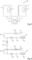
- FIG. 1 shows a charging system 10 according to embodiments described herein.
- the charging system 10 may be, for example, a charging system for charging electric cars, in particular electrically powered cars.
- the charging system 10 typically includes two charging stations 1 and 2.
- Each of the charging stations 1, 2 may have one or more charging plugs, to each of which an electric vehicle can be connected for charging.
- the number of charging columns of a charging system according to embodiments described herein is not limited to two.
- the charging system may have more than two charging posts.
- the charging system 10 according to the invention may also have only one charging station 1.
- the charging system comprises a buffer memory, which in the in FIG. 1 shown example in the form of two batteries 4 and 5 is shown.
- the first battery 4 of the buffer is mounted in the first charging station 1 and the second battery 5 of the buffer in the second charging station 2.
- the two batteries 4 and 5 of the buffer may be substantially the same size.
- the charging stations 1 and 2 can be connected by a charging station 3 with each other galvanically isolated.
- the charging station 3, the power electronics 6 and may further include, for example, a cooling, processors, measuring devices, switching devices and other elements.
- the two charging stations 1 and 2 are connected electrically isolated by the common power electronics 6, which is arranged centrally in the charging station 3.
- the charging station 3 may further include a power connector (not explicitly shown) coupled to the power electronics 6. In the basic form of the charging system 10 according to the invention, this can only have the charging station 3 together with the power electronics 6, which is coupled to the first charging station 1.
- the system according to the invention may consist of two units: a charging station with the buffer memory and the power electronics (and other elements, as already mentioned above by way of example) on the one hand and the actual charging station with the charging plugs for the electric vehicle on the other.
- the charging station can be arranged separately from the charging stations, for example at a distance of a few tens to a few hundred meters distance.
- the charging system 10 may have a number of other elements required for operating a charging system for charging an electric vehicle.
- the charging system may include other elements of the power electronics, connectors, plugs, cables, groundings, control systems, processors, measuring devices, etc.
- the buffer memory may be a battery, in particular a rechargeable battery.
- the buffer memory can be divided into two batteries or divided into a number of batteries, which corresponds to the number of charging columns of the charging system according to the invention.
- the division of the battery can be associated with the individual charging stations.
- the integrated buffer memory can be designed with capacities in the range of approximately 50 kWh to approximately 500 kWh such that a mains connection for supplying energy is superfluous, at least while charging the electric vehicles.
- the buffer memory is designed to charge one or more electric vehicles, in particular cars.
- the capacity of the buffer memory can be dimensioned so that the simultaneously charged electric vehicles can only be charged by the energy from the buffer memory and without energy flow from the mains connection.
- the charging system does not depend on a mains connection or a mains connection of a certain size.
- the charging system can be connectable to a power grid, in particular to a power grid with a small network power. Thus, despite low network performance, a large and fast charging power of the electric vehicle can be guaranteed.
- FIG. 2 shows a switching device of a charging system according to embodiments of the invention. Shown are in the example of FIG. 2 the first battery 4 of the first charging station 1, to which a first electric vehicle 40 to be charged is connected. Furthermore, the shows FIG. 2 a second battery 5 of the second charging station 2 with a second electric vehicle 50 connected thereto.
- the switching device of the charging system has a plurality of switches, namely a first switch 20, a second switch 21, a third switch 22, a fourth switch 23 and a fifth switch 24 ,
- the first electric vehicle 40 which is connected to the first charging station 1, can be connected to the first battery 4 for charging via the first switch 20 and the second switch 21 and via the first connection 30 and the second connection 31.
- the second electric vehicle 50 can be connected to the second battery 5 of the second charging station 2 via the fourth switch 23 and the fifth switch 24 and via the fourth connection 33 and the fifth connection 34.
- the power does not have to be split between the charging points, but can be provided in full at each charging point if required. Both the first electric vehicle 40 and the second electric vehicle 50 thus the maximum energy from the batteries is available for charging.
- Switching device shown which may generally correspond to at least a part of the power electronics, also has a third switch 22 and a third connection 32.
- the third connection 32 connects as described herein Embodiments, the first connection 30 of the first charging station 1 with the fourth connection 33 of the second charging station 2.
- the third switch 22 can connect or disconnect this connection.
- the first electric vehicle 40 connected to the first charging pole 1 may also be charged through the battery 5 via the third connection 32 and the closed third switch 22.
- the first electric vehicle 40 may also be charged via both batteries, the first battery 4 and the second battery 5.
- the second electric vehicle 50 may be connected to the battery 4 of the first charging pole 1 via the fifth connection 34, the fourth connection 33, the third connection 32, and the first connection 30. Also, the second electric vehicle 50 may be connected with the appropriate switch position with both batteries 4 and 5 of the two charging stations.
- the first switch 20 and the first battery 4 may, as in FIG. 1 be shown, be arranged in the first charging station 1 or alternatively be arranged centrally in the charging station.
- the situation is similar with the arrangement of the fourth switch 23 and the second battery 5 with respect to the second charging station 2.
- the switches 21 and 24 may be arranged in the charging station or the charging station.
- the switching device as defined above, can be arranged centrally in the charging station or arranged distributed on the charging station and the charging columns 1, 2.
- the third switch 22 may be arranged in the charging station.
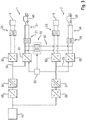
- FIG. 3 shows a diagram of the system according to embodiments described herein.
- the diagram of FIG. 3 includes in the right part of the switching device, as simplified in the FIG. 2 was shown and described.
- the first charging station 1 with the first battery 4 and the first electric vehicle 40 and the second charging station 2 with the second battery 5 and the second electric vehicle 50 can be seen.
- the battery and current paths of the charging columns 1 and 2 are through the first connection 30, the second connection 31, the third connection 32, the fourth connection 33, and the fifth connection 34 and the first switch 20, the second switch 21, the third switch 22, the fourth switch 23, and the fifth switch 24 connectable to each other.
- the double lines, each from the first DC / DC controller 60th to the first battery 4, from the second DC / DC adjuster 61 to the first electric vehicle 40, from the third DC / DC adjuster 62 to the second battery 5 and from the fourth DC / DC adjuster 63 to the second electric vehicle 50 are representative of positive pole and Negative pole has been shown.
- first charging station 1 first and second DC / DC regulators 60, 61; second charging station 2: third and fourth DC / DC regulators 62, 63)
- first charging station 1 first and second DC / DC regulators 60, 61; second charging station 2: third and fourth DC / DC regulators 62, 63
- second charging station 2 third and fourth DC / DC regulators 62, 63
- the voltage is first at each charging station 1, 2 independently converted by the associated DC / DC controller.
- the FIG. 3 also shows a mains connection 70 and parts of the power electronics of the charging system according to the invention.
- a first rectifier 65 and a second rectifier 66 and a first DC-DC converter 64 and a second DC-DC converter 67 are shown.
- the grid connection 70 can be used for charging the buffer memory, in particular for charging the batteries 4 and 5, or directly for charging the first electric vehicle 40 via the second DC / DC controller 61 and / or for charging the second electric vehicle 50 via the fourth DC / DC adjuster 63 are used.
- a voltage converter control unit 80 which ensures that the interconnection functions smoothly, for example by monitoring the charging currents.
- the use of two DC / DC controllers per charging station 1, 2 also allows the use of comparatively smaller and less expensive DC-DC converter, since the voltage swing when charging the batteries 4, 5 by means of the mains connection 70 and charging the electric vehicles 40, 50 by means of batteries 4, 5 need not be provided by a single DC-DC converter.
- the transmitted through the common power electronics energy is already transmitted as DC and DC voltage to the respective charging stations 1 and 2.
- the charging system may comprise further elements.
- the charging system may include isolation monitors, grounding devices, other circuitry, and so on.
- a method for powering a charging system for charging one or more electric vehicles.
- the charging system may in particular be a charging system, as has been described herein according to embodiments.
- the method comprises providing a buffer memory, which can be coupled to the first charging station and to the second charging station, wherein the buffer memory can typically be realized in the form of a battery associated with the two charging stations.
- the switching device By the switching device according to the invention, with the two Charging columns are electrically isolated, the batteries of the buffer memory can be joined together.
- a control device may control the opening or closing of connections by means of a switching device. For example, depending on the vehicles connected to the charging stations, the control device may determine how the energy of the buffer memory is shared among the charging stations or which connections to the batteries of the buffer memory are opened or closed.
- the method may include further steps, such as acquiring several parameters. These parameters may include the number of connected vehicles, the state of charge of the connected vehicles, the state of charge of the buffer, the duration of the connection to the vehicle, and the like. In one embodiment, the capture of the parameters, the storage of the parameters, the calculation of the consequences, the optimization of the individual loads, the corresponding control signal generation, etc., may be performed by a processor unit.
- the provision of the buffer memory may include providing a plurality of batteries corresponding to the number of charging columns and providing a corresponding circuit, as described, for example, in US Pat FIG. 2 was explained in more detail.
Landscapes
- Engineering & Computer Science (AREA)
- Power Engineering (AREA)
- Transportation (AREA)
- Mechanical Engineering (AREA)
- Charge And Discharge Circuits For Batteries Or The Like (AREA)
- Electric Propulsion And Braking For Vehicles (AREA)
Abstract
Description
- Die vorliegende Erfindung betrifft ein Ladesystem sowie ein Verfahren zum Laden von Elektrofahrzeugen. Insbesondere betrifft die vorliegende Erfindung ein Ladesystem mit einer Ladestation, mindestens einer ersten Ladesäule und optional einer zweiten Ladesäule zum Laden von Elektrofahrzeugen und ein Verfahren zum Laden von Elektrofahrzeugen mittels Ladesystem, das eine Ladestation, mindestens eine erste Ladesäule und optional eine zweite Ladesäule aufweist. Insbesondere ist das Ladesystem ein Ladesystem für elektrisch angetriebene PKWs.
- Der Elektromobilität ist in den letzten Jahren eine immer größer werdende Bedeutung zugekommen. Um die Verbreitung von Elektrofahrzeugen voranzubringen, ist es wünschenswert, dass der Ladevorgang eines Elektrofahrzeuges schnell, unkompliziert und jederzeit möglich ist. Dabei ist es im Sinne einer guten Zugänglichkeit von Elektrotankstellen möglich, mehrere Fahrzeuge an einer Ladesäule mit mehreren Ladesteckern zu laden. Bei den Ladesäulen mit mehreren Ladesteckern wird eine Stromquelle zum Laden mehrerer Fahrzeuge verwendet. Die Leistung verteilt sich dann auf alle angeschlossenen Fahrzeuge. Dies verringert jedoch die Leistung, die pro Fahrzeug aufgebracht werden kann und verlängert die Ladezeiten der Elektrofahrzeuge.
- Die meisten heutigen Ladesäulen sind so aufgebaut, dass sie eine Leistungselektronik enthalten und mit dieser ein bis drei Ladestecker bedienen. Wird mehr als eine Ladesäule bereitgestellt, so wird auch eine Leistungselektronik für jede Ladesäule vorgesehen. Die Leistungselektronik führt die Umformung des Stroms und der Spannung von einem Netzanschluss durch, so dass der Strom und die Spannung an den Ladesteckern die geeignete Form (DC oder AC) und Größe aufweist, um ein Elektrofahrzeug aufladen zu können (z.B. Gleichstrom in Höhe von 48 A).
- Die europäische Anmeldung
EP3035478 A1 beschreibt eine Ladestation zum Bereitstellen elektrischer Energie für ein elektrisch betreibbares Fahrzeug und eine Anordnung von mehreren Ladestationen, die an ein Versorgungsnetz angeschlossen sind. Die AnmeldungUS2011/291616A betrifft ein Ladegerät, das eine Ladeanordnung mit einem Wechselstromterminal zum Zuführen des Wechselstroms, einem Gleichrichter zum Wandeln der Wechselspannung in eine Gleichspannung, und ein Gleichstromterminal zur Ausgabe des Gleichstroms aufweist. - Die Anmeldung
US2011/175569A beschriebt einen Controller für eine Ladestation. Die AnmeldungUS 2013/169227A beschäftigt sich mit einer modularen Ladestation mit einem Controller und einem Schalter zum Ein- und Ausschalten der Energiezufuhr. Die AnmeldungUS 2016/137082A beschreibt einen Zusatzadapter, der es ermöglicht, an einem einzelnen Ladeanschluss zwei Elektrofahrzeuge simultan zu laden. Die AnmeldungUS2016/193932A stellt einen Ladestation-Expander bereit, der elektrische Energie von einer Ladestation erhält und die elektrische Energie auf zumindest ein Elektrofahrzeug verteilt. - Es ist Aufgabe der vorliegenden Erfindung, ein Ladesystem für Elektrofahrzeuge bereitzustellen, welches möglichst flexibel an verschiedene Ladeszenarien anpassbar ist bezüglich der Bereitstellung von Energie an und ihrer Aufteilung auf mehrere Ladesäulen.
- Die Aufgabe wird mit einer Vorrichtung gemäß Patentanspruch 1 und einem Verfahren gemäß Patentanspruch 10 gelöst. Ausgestaltungen ergeben sich aus den abhängigen Patentansprüchen und der beiliegenden Beschreibung.
- Erfindungsgemäß wird ein Ladesystem mit einer Ladestation, mindestens einer ersten Ladesäule, die einen oder mehrere Ladestecker aufweist, und einem Netzanschluss zum Bereitstellen von Energie an die Ladestation bereitgestellt. Das erfindungsgemäße Ladesystem kann mindestens eine zweite Ladesäule aufweisen. Das Ladesystem umfasst ferner einen Pufferspeicher, insbesondere einen Pufferspeicher und einen Netzanschluss zum Bereitstellen von Energie an die Ladestation. Bei dem Pufferspeicher kann es sich um einen aufteilbaren Pufferspeicher handeln, welcher in einem Ladesystem mit zwei Ladesäulen bezüglich jeder der Ladesäulen individuell schaltbar ist oder zusammengeschaltet auf eine der Ladesäulen zusammen mit dem Netzanschluss geschaltet werden kann. Weiterhin weist das Ladesystem eine Schaltvorrichtung auf, wobei die Schaltvorrichtung eingerichtet ist, den Energiefluss aus dem Pufferspeicher und/oder dem Netzanschluss zu der ersten oder zweiten Ladesäule zu leiten.
- Durch die erfindungsgemäße Vorrichtung kann mindestens die erste oder zweite Ladesäule mit einem oder mehreren Ladesteckern des Ladesystems mit Energie versorgt werden. Insbesondere ermöglicht das Ladesystem bei Vorliegen von zwei Ladesäulen gemäß hierin beschriebenen Ausführungsformen, die Energiebereitstellung und die Energieaufteilung auf die Ladesäulen in mehreren Kombinationen auszuführen. Dabei kann das Ladesystem insbesondere durch den Pufferspeicher mit kleinen Netzleistungen geladen werden und große Leistungen zum Laden von Elektrofahrzeugen abgeben. Die erfindungsgemäße Anordnung mit Pufferspeicher und Schaltvorrichtung erlaubt es, die maximal bereitstellbare Energie an einer Ladesäule oder an jeweils einer von zwei Ladesäulen zur Verfügung zu stellen.
- Gemäß weiteren Ausführungsbeispielen kann das Ladesystem eine zweite Ladesäule mit einen oder mehreren Ladesteckern aufweisen. Im Allgemeinen kann das hier beschriebene Ladesystem auch mehr als zwei Ladesäulen aufweisen. Im Rahmen der vorliegenden Beschreibung kann das hier vorgestellte Ladesystem mit zwei Ladesäulen für ein System mit mehr als zwei Ladesäulen (beispielsweise drei, vier, fünf oder mehr Ladesäulen) repräsentativ sein. Insbesondere kann die Schaltvorrichtung eingerichtet sein, den Energiefluss aus dem Pufferspeicher und/oder dem Netzanschluss auf die beiden Ladesäulen zu verteilen oder ihn zu einer der beiden Ladesäulen zu leiten. In einem Ladeszenario kann die Energie zum Laden des mindestens einen Elektrofahrzeugs primär aus dem Netzanschluss bezogen werden und der Pufferspeicher kann verwendet werden, um eine möglicherweise entstehende Energielücke zu schließen. Durch einen größtenteils aus dem Netzanschluss stattfindenden Energiefluss kann der Pufferspeicher geschont werden, da er so weniger oft Entlade- und Ladevorgängen ausgesetzt ist.
- Gemäß hierin beschriebenen Ausführungsformen kann der Pufferspeicher durch eine Batterieaufteilung auf die einzelnen Säulen verteilt sein, so dass der Strom nicht zwischen den Ladepunkten aufgeteilt werden muss, sondern für jeden Ladepunkt in voller Höhe bereitgestellt werden kann. Für die flexible Bereitstellung der Energie an zwei Ladesäulen kann der Energiefluss aus dem Pufferspeicher sowohl auf die zwei Ladesäulen aufgeteilt werden (bei gleichzeitigem Laden an beiden Ladesäulen), als auch zusammengeführt werden (beim Laden an nur einer Ladesäule). Dadurch erhöht sich die Flexibilität des Ladesystems für verschiedene Situationen, so dass insbesondere die Ladezeit für den Kunden gesenkt werden kann, wodurch die Akzeptanz der Elektromobilität erhöht wird.
- In einer Ausführungsform umfasst das erfindungsgemäße Ladesystem einen Netzanschluss, insbesondere einen Netzanschluss zum Laden des Pufferspeichers. Durch den Netzanschluss kann der Pufferspeicher geladen werden, wobei der Netzanschluss für kleine Leistungen ausgelegt werden kann, beispielsweise Leistungen im Bereich von ca. 10 kW bis 300 kW. Aufgrund der Tatsache, dass bei dem erfindungsgemäßen Ladesystem ein Netzanschluss mit kleiner Leistung genügt, was die Anforderungen an einen potentiellen Aufstellungsort des Ladesystems verringert, ist das Ladesystem gemäß hierin beschriebenen Ausführungsformen flexibel einsetzbar und kann zur weiteren Verbreitung der Elektromobilität beitragen.
- Gemäß einer Ausführungsform weist der Pufferspeicher eine Batterie auf. Insbesondere kann der Pufferspeicher eine wiederaufladbare Batterie aufweisen. Alternativ oder zusätzlich ist der erfindungsgemäße Pufferspeicher auf je eine Batterie bzw. Batterieeinheit für jede Ladesäule aufgeteilt. Dabei ist typischerweise je eine Batterie bzw. Batterieeinheit mit einer Ladesäule assoziiert. Die Gestaltung des Pufferspeichers als Batterie und die Aufteilung auf je eine Einheit pro Ladesäule ermöglicht es, verschiedene Schaltersituationen zu realisieren und so eine große Flexibilität beim Ladevorgang an den beiden Ladesäulen zu erreichen. So kann eine flexible Schaltung des Pufferspeichers und eine situationsgemäße Verteilung der Energie auf die Ladesäulen einfach realisiert werden. Gemäß hierin beschriebenen Ausführungsformen kann eine Batterie, die mit einer Ladesäule assoziiert ist, dieser Ladesäule zugeordnet oder zugewiesen sein (insbesondere schaltbar zugeordnet oder zugewiesen) und/oder sich in dieser Ladesäule befinden. In einer Ausführungsform kann eine Batterie zwar einer Ladesäule zugeordnet oder zugewiesen sein, aber sich in der Ladestation, insbesondere außerhalb der Ladesäule, befinden. Typischerweise kann eine Assoziierung, wie sie hierin verwendet wird, eine 1:1 Zuordnung einer Batterie zu einer Ladesäule bedeuten, wobei sich die Batterien in der Ladestation oder in der jeweiligen Ladesäule befinden können.
- Typischerweise kann der Pufferspeicher in den Ladesäulen des Ladesystems angeordnet sein. Insbesondere können die Batterien, bzw. Batterieeinheiten des Pufferspeichers in den Ladesäulen angeordnet sein. In anderen Ausführungsformen kann das Ladesystem aus zwei Einheiten bestehen: Einer Ladestation, die die Leistungselektronik und den Pufferspeicher enthält (und weitere Elemente, wie zum Beispiel die Kühlung), und die Ladesäulen mit den Ladesteckern. Dies fördert eine kompakte Bauweise der Ladesäulen. Dabei können die Ladesäulen auch entfernt von der Ladestation aufgestellt sein (zum Beispiel in einer Entfernung von einigen zehn bis zu einigen hundert Metern).
- Gemäß hierin beschriebenen Ausführungsformen ist die Schaltvorrichtung derart ausgebildet, dass die maximale Energie des Ladesystems an je einer der Ladesäulen bereitgestellt werden kann. Die Bereitstellung eines Pufferspeichers für die Ladesäulen, die Aufteilung des Pufferspeichers sowie das Zusammenschalten einzelner Teile bzw. Einheiten des Pufferspeichers ermöglicht eine gesteigerte und an die entsprechende Ladesituation optimal angepasste Ladeleistung an beiden Ladesäulen. Dadurch können die Ladezeiten an dem erfindungsgemäßen Ladesystem optimiert werden.
- In einer weiteren Ausgestaltung der Erfindung können die beiden Ladesäulen durch zwei Leistungselektroniken bedient werden, wobei die Energie schon als Gleichstrom/Gleichspannung auf die Ladesäulen übertragen wird. Bevorzugt können die Leistungselektroniken in der Ladestation untergebracht sein. Zudem können die beiden Leistungselektroniken gleich sein. Die Leistungselektroniken erlauben es, die Ladesäulen flexibel anzusteuern. Insbesondere können die Ladesituationen der zwei Ladesäulen unabhängig voneinander bewertet und das Ladeschema darauf abgestimmt werden.
- In einer Ausgestaltung des erfindungsgemäßen Ladesystems kann der Pufferspeicher eine erste Batterie (oder erste Batterieeinheit) für die erste Ladesäule und eine zweite Batterie (oder zweite Batterieeinheit) für die zweite Ladesäule aufweisen, wobei die erste Batterie mit der zweiten Ladesäule (und deren Ladesteckern) und die zweite Batterie mit der ersten Ladesäule (und deren Ladesteckern) koppelbar ist. Insbesondere erlaubt die Schaltvorrichtung eine solche Verbindung. Dadurch wird sowohl eine große Flexibilität erreicht, als auch ein bedarfsgemäßes Bereitstellen von Energie an die jeweilige Ladesäule. Typischerweise können die erste Batterieeinheit und die zweite Batterieeinheit in der jeweilig entsprechenden Ladesäule untergebracht sein oder in der Ladestation.
- Die Kapazität des Pufferspeichers kann typischerweise so ausgelegt werden, dass mindestens zwei Elektrofahrzeuge, z.B. elektrisch betriebene PKWs, mit Energie versorgt bzw. aufgeladen werden können. Gemäß einigen Ausführungsformen kann die Kapazität des Pufferspeichers so groß gewählt werden, dass er eine Anzahl von Elektrofahrzeugen mit Energie versorgen kann, die beispielsweise mindestens der Anzahl der Ladesäulen entspricht. Mit einer derartig groß gewählten Kapazität des Pufferspeichers können die Ladesäulen zuverlässig mit Energie versorgt werden, ohne in der konkreten Ladesituation des Fahrzeugs auf die Energiebereitstellung aus dem Netzanschluss angewiesen zu sein. Der Pufferspeicher kann kontinuierlich durch den Netzanschluss geladen werden, und zugleich die Elektrofahrzeuge mit Energie versorgen. Hierbei kann der Ladestrom aus dem Netzanschluss zum Pufferspeicher geringer sein als der Ladestrom, der aus dem Pufferspeicher an die Elektrofahrzeuge fließt. Damit erfüllt der Pufferspeicher die Funktion eines Puffers, welcher Ladung zwischenpuffert und sie bei Bedarf im größeren Umfang, als es der existierende Netzanschluss erlaubt, zur Verfügung stellt.
- Gemäß einem Aspekt der vorliegenden Erfindung wird ein Verfahren zum Laden eines oder mehrerer Elektrofahrzeuge durch ein Ladesystem bereitgestellt mit einer Ladestation, einer ersten Ladesäule, einem Pufferspeicher zum Speichern von Energie, einem Netzanschluss zum Bereitstellen von Energie an die Ladestation und einer Schaltvorrichtung, wobei das Verfahren ein Schalten der Schaltvorrichtung des Ladesystems aufweist, um den Energiefluss aus dem Pufferspeicher und/oder dem Netzanschluss zu der mindestens ersten Ladesäule zu leiten. In einer Ausführungsform kann das Ladesystem ein Ladesystem gemäß hierin geschriebenen Ausführungsformen sein.
- In weiteren Ausführungsbeispielen des Verfahrens zum Laden eines oder mehrerer Elektrofahrzeuge kann die zugrunde liegende Ladestation mindestens eine zweite Ladesäule aufweisen und das Verfahren kann ferner ein Schalten der Schaltvorrichtung des Ladesystems aufweisen, um den Energiefluss aus dem Pufferspeicher und/oder aus dem Netzanschluss der Ladestation zwischen der ersten Ladesäule und der zweiten Ladesäule aufzuteilen oder den Energiefluss zu einer der beiden Ladesäulen zu leiten. Die Schaltvorrichtung kann auch so ausgelegt sein, dass ein gleichzeitiges Laden einer Batterie des Ladesystems und des an der Ladesäule angeschlossenen Elektrofahrzeugs möglich ist. Dieses kann unter anderem durch die Verwendung von mindestens zwei Gleichspannungswandlern pro Ladesäule erreicht werden. Das erfindungsgemäße Verfahren kann auch ein Dazuschalten des Pufferspeichers beim Laden mindestens eines Elektrofahrzeugs aufweisen, während die Hauptladelast vom Netzanschluss getragen wird, beispielsweise wenn die Netzleistung zu gering ist, um die an die Ladestation(en) angeschlossenen Elektrofahrzeuge mit maximalem Ladestrom zu laden.
- Weitere Vorteile und Ausgestaltungen der Erfindung ergeben sich aus der Beschreibung und den beiliegenden Zeichnungen.
- Es versteht sich, dass die voranstehend genannten und die nachstehend noch zu erläuternden Merkmale nicht nur in der jeweils angegebenen Kombination, sondern auch in anderen Kombinationen oder in Alleinstellung verwendbar sind, ohne den Rahmen der vorliegenden Erfindung zu verlassen.
- Die Erfindung ist anhand von Ausführungsformen in den Zeichnungen schematisch dargestellt und wird unter Bezugnahme auf die Zeichnungen schematisch und ausführlich beschrieben.
-
Figur 1 zeigt eine schematische Zeichnung eines Ladesystems mit zwei Ladesäulen gemäß hierin beschriebenen Ausführungsformen. -
Figur 2 zeigt eine schematische Zeichnung einer Schaltvorrichtung eines Ladesystems mit zwei Ladesäulen gemäß hierin beschriebenen Ausführungsformen. -
Figur 3 zeigt ein schematisches Diagramm eines Ladesystems mit zwei Ladesäulen gemäß hierin beschriebenen Ausführungsformen. -
Figur 1 zeigt ein Ladesystem 10 gemäß hierin beschriebenen Ausführungsformen. Das Ladesystem 10 kann zum Beispiel ein Ladesystem zum Laden von Elektroautos sein, insbesondere von elektrisch betriebenen PKWs. Das Ladesystem 10 umfasst typischerweise zwei Ladesäulen 1 und 2. Jede der Ladesäulen 1, 2 kann einen oder mehrere Ladestecker aufweisen, mit denen jeweils ein Elektrofahrzeug zum Aufladen verbunden werden kann. Die Anzahl der Ladesäulen eines Ladesystems gemäß hierin beschriebenen Ausführungsformen ist nicht auf zwei beschränkt. Zum Beispiel kann das Ladesystem mehr als zwei Ladesäulen aufweisen. Insbesondere kann das erfindungsgemäße Ladesystem 10 auch nur eine Ladesäule 1 aufweisen. - Gemäß hierin beschriebenen Ausführungsformen weist das Ladesystem einen Pufferspeicher auf, der in dem in
Figur 1 gezeigten Beispiel in Form zweier Batterien 4 und 5 dargestellt ist. In dem inFigur 1 gezeigten Beispiel ist die erste Batterie 4 des Pufferspeichers in der ersten Ladesäule 1 angebracht und die zweite Batterie 5 des Pufferspeichers in der zweiten Ladesäule 2. Gemäß einigen hierin beschriebenen Ausführungsformen können die beiden Batterien 4 und 5 des Pufferspeichers im Wesentlichen gleich groß sein. Die Ladesäulen 1 und 2 können durch eine Ladestation 3 miteinander galvanisch getrennt verbunden sein. In der gezeigten Ausführungsform weist die Ladestation 3 die Leistungselektronik 6 auf und kann ferner beispielsweise eine Kühlung, Prozessoren, Messvorrichtungen, Schaltvorrichtungen und weitere Elemente aufweisen. InFigur 1 sind der Einfachheit halber die beiden Ladesäulen 1 und 2 schematisch durch die gemeinsame Leistungselektronik 6 galvanisch getrennt verbunden, welche zentral in der Ladestation 3 angeordnet ist. Die Ladestation 3 kann ferner einen Netzanschluss aufweisen (nicht explizit gezeigt), welcher mit der Leistungselektronik 6 gekoppelt ist. In der Grundform des erfindungsgemäßen Ladesystems 10 kann dieses nur die Ladestation 3 samt Leistungselektronik 6 aufweisen, die mit der ersten Ladesäule 1 gekoppelt ist. - Obwohl die
Figur 1 die Batterien 4 und 5 des Pufferspeichers des Ladesystems in den Ladesäulen 1 und 2 zeigt, sind auch andere Ausführungsformen der Anordnung möglich. Zum Beispiel kann das erfindungsgemäße System aus zwei Einheiten bestehen: Einer Ladestation mit dem Pufferspeicher und der Leistungselektronik (und weiteren Elementen, wie oben bereits beispielhaft erwähnt) zum einen und der eigentlichen Ladesäule mit den Ladesteckern zum Elektrofahrzeug zum anderen. Dabei kann die Ladestation getrennt von den Ladesäulen angeordnet sein, zum Beispiel in einem Abstand von einigen zehn bis zu einigen hundert Metern Entfernung. - Das erfindungsgemäße Ladesystem 10 kann, obwohl der Einfachheit halber nicht in den Figuren gezeigt, etliche weitere Elemente aufweisen, die für den Betrieb eines Ladesystems zum Laden eines Elektrofahrzeugs benötigt werden. Zum Beispiel kann das Ladesystem weitere Elemente der Leistungselektronik, Anschlüsse, Stecker, Kabel, Erdungen, Kontrollsysteme, Prozessoren, Messvorrichtungen, usw. aufweisen.
- Der Pufferspeicher gemäß hierin beschriebenen Ausführungsformen kann eine Batterie, insbesondere eine wiederaufladbare Batterie sein. In einigen Ausführungsformen, wie sie beispielhaft in den Figuren gezeigt sind, kann der Pufferspeicher auf zwei Batterien aufgeteilt sein oder auf eine Anzahl Batterien aufgeteilt sein, die der Anzahl der Ladesäulen des erfindungsgemäßen Ladesystems entspricht. Insbesondere kann die Aufteilung der Batterie mit den einzelnen Ladesäulen assoziiert sein.
- Der integrierte Pufferspeicher kann mit Kapazitäten im Bereich von ca. 50 kWh bis ca. 500 kWh derart ausgelegt sein, dass ein Netzanschluss zur Versorgung mit Energie überflüssig wird, zumindest während des Ladens der Elektrofahrzeuge. Insbesondere ist der Pufferspeicher ausgelegt, ein oder mehrere Elektrofahrzeuge, insbesondere PKWs, zu laden. Die Kapazität des Pufferspeichers kann so dimensioniert werden, dass die gleichzeitig geladenen Elektrofahrzeuge nur durch die Energie aus dem Pufferspeicher und ohne Energiefluss aus dem Netzanschluss geladen werden können. Dadurch ist das Ladesystem nicht von einem Netzanschluss, oder einem Netzanschluss einer bestimmten Größe abhängig. Zusätzlich oder alternativ zu einem derartigen Pufferspeicher kann das Ladesystem mit einem Stromnetz verbindbar sein, insbesondere mit einem Stromnetz mit kleiner Netzleistung. Damit kann trotz geringer Netzleistung eine große und schnelle Ladeleistung des Elektrofahrzeugs gewährleistet werden.
-
Figur 2 zeigt eine Schaltvorrichtung eines Ladesystems gemäß Ausführungsformen der Erfindung. Gezeigt sind in dem Beispiel derFigur 2 die erste Batterie 4 der ersten Ladesäule 1, mit der ein zu ladendes erstes Elektrofahrzeug 40 verbunden ist. Weiterhin zeigt dieFigur 2 eine zweite Batterie 5 der zweiten Ladesäule 2 mit einem damit verbundenen zweiten Elektrofahrzeug 50. Die Schaltvorrichtung des Ladesystems weist mehrere Schalter, nämlich einen ersten Schalter 20, einen zweiten Schalter 21, einen dritten Schalter 22, einen vierten Schalter 23 und einen fünften Schalter 24 auf. Das erste Elektrofahrzeug 40, das mit der ersten Ladesäule 1 verbunden ist, kann über den ersten Schalter 20 und den zweiten Schalter 21 und über die erste Verbindung 30 und die zweite Verbindung 31 mit der ersten Batterie 4 zum Laden verbunden werden. Das zweite Elektrofahrzeug 50 kann über den vierten Schalter 23 und den fünften Schalter 24 und über die vierte Verbindung 33 und die fünfte Verbindung 34 mit der zweiten Batterie 5 der zweiten Ladesäule 2 verbunden werden. Dabei muss der Strom nicht zwischen den Ladepunkten aufgeteilt werden, sondern kann bei Bedarf an jedem Ladepunkt in voller Höhe bereitgestellt werden. Sowohl dem ersten Elektrofahrzeug 40 als auch dem zweiten Elektrofahrzeug 50 steht somit die maximale Energie aus den Batterien zum Laden zur Verfügung. - Die in
Figur 2 gezeigte Schaltvorrichtung, welche im Allgemeinen zumindest einem Teil der Leistungselektronik entsprechen kann, weist außerdem einen dritten Schalter 22 und eine dritte Verbindung 32 auf. Die dritte Verbindung 32 verbindet gemäß hierin beschriebenen Ausführungsformen die erste Verbindung 30 der ersten Ladesäule 1 mit der vierten Verbindung 33 der zweiten Ladesäule 2. Der dritte Schalter 22 kann diese Verbindung herstellen oder trennen. Somit kann zum Beispiel das erste Elektrofahrzeug 40, das mit der ersten Ladesäule 1 verbunden ist, auch über die dritte Verbindung 32 und den geschlossenen dritten Schalter 22 durch die Batterie 5 geladen werden. In einem Beispiel kann das erste Elektrofahrzeug 40 auch über beide Batterien, die erste Batterie 4 und die zweite Batterie 5 geladen werden. In einem anderen Beispiel kann das zweite Elektrofahrzeug 50 über die fünfte Verbindung 34, die vierte Verbindung 33, die dritte Verbindung 32 und die erste Verbindung 30 mit der Batterie 4 der ersten Ladesäule 1 verbunden werden. Auch das zweite Elektrofahrzeug 50 kann bei entsprechender Schalterstellung mit beiden Batterien 4 und 5 der beiden Ladesäulen verbunden sein. - Der erste Schalter 20 und die erste Batterie 4 können, wie in
Figur 1 gezeigt, in der ersten Ladesäule 1 angeordnet sein oder alternativ auch zentral in der Ladestation angeordnet sein. Analog verhält es sich mit der Anordnung des vierten Schalters 23 und der zweiten Batterie 5 bezüglich der zweiten Ladestation 2. Auch die Schalter 21 und 24 können in der Ladestation oder der Ladesäule angeordnet sein. Die Schaltvorrichtung, wie oben definiert, kann zentral in der Ladestation angeordnet sein oder auf die Ladestation und die Ladesäulen 1, 2 verteilt angeordnet sein. Üblicherweise kann der dritte Schalter 22 in der Ladestation angeordnet sein. -
Figur 3 zeigt ein Diagramm des Systems gemäß hierin beschriebenen Ausführungsformen. Das Diagramm derFigur 3 umfasst im rechten Teil die Schaltvorrichtung, wie sie vereinfacht in derFigur 2 gezeigt und beschrieben wurde. Dabei ist die erste Ladesäule 1 mit der ersten Batterie 4 und dem ersten Elektrofahrzeug 40 und die zweite Ladesäule 2 mit der zweiten Batterie 5 und dem zweiten Elektrofahrzeug 50 zu sehen. Wie oben im Detail beschrieben, sind die Batterie- und Strompfade der Ladesäulen 1 und 2 durch die erste Verbindung 30, die zweite Verbindung 31, die dritte Verbindung 32, die vierte Verbindung 33, und die fünfte Verbindung 34 und den ersten Schalter 20, den zweiten Schalter 21, den dritten Schalter 22, den vierten Schalter 23, und den fünften Schalter 24 miteinander verbindbar. Die Doppelleitungen, welche jeweils vom ersten DC/DC-Steller 60 zur ersten Batterie 4, vom zweiten DC/DC-Steller 61 zum ersten Elektrofahrzeug 40, vom dritten DC/DC-Steller 62 zur zweiten Batterie 5 und vom vierten DC/DC-Steller 63 zum zweiten Elektrofahrzeug 50 verlaufen, sind repräsentativ für Pluspol und Minuspol dargestellt worden. - Die in
Fig. 3 dargestellte beispielhafte Schalttopologie kann als vorteilhaft angesehen werden, da die DC/DC-Steller der Ladestationen (erste Ladesäule 1: erster und zweiter DC/DC-Steller 60, 61; zweite Ladesäule 2: dritter und vierter DC/DC-Steller 62, 63) für Leistungen ausgelegt werden können, die sich am Ladevorgang eines Elektrofahrzeugs 40, 50 orientieren und damit vergleichsweise kostengünstiger und kompakter sind, da sie nur etwas mehr als die halbe mögliche Leistung eines Ladepunktes bereitstellen. Beim Zusammenschalten der ersten und zweiten Batterie 4, 5 über den dritten Schalter 22 zwecks Laden eines der beiden Elektrofahrzeuge 40, 50 wird die Spannung zunächst an jeder Ladestation 1, 2 unabhängig voneinander durch die dazugehörigen DC/DC-Steller gewandelt. Erst am Ende, d.h. zwischen dem DC/DC-Steller 61 und dem Schalter 21 und analog zwischen dem DC/DC-Steller 63 und dem Schalter 24, erfolgt die Zusammenführung der Ladeströme, so dass zu keinem Zeitpunkt ein Ladestrom durch die DC/DC-Steller 60, 61, 62, 63 der ersten und zweiten Ladestation 1, 2 fließt, welcher der Summe des Ladestroms aus der ersten Batterie 4 und zweiten Batterie 5 entspricht. - Die
Figur 3 zeigt außerdem einen Netzanschluss 70 und Teile der Leistungselektronik des erfindungsgemäßen Ladesystems. Insbesondere sind in derFigur 3 ein erster Gleichrichter 65 und ein zweiter Gleichrichter 66 sowie ein erster Gleichspannungswandler 64 und ein zweiter Gleichspannungswandler 67 gezeigt. Damit kann der Netzanschluss 70 zum Laden des Pufferspeichers, insbesondere zum Laden der Batterien 4 und 5 verwendet werden oder aber direkt zum Laden des ersten Elektrofahrzeugs 40 über den zweiten DC/DC-Steller 61 und/oder zum Laden des zweiten Elektrofahrzeugs 50 über den vierten DC/DC-Steller 63 benutzt werden. Die Energie jeder der inFigur 3 beispielhaft gezeigten Batterien 4 und 5 geht durch einen ersten DC/DC-Steller 60 und einen zweiten DC/DC-Steller 61, bzw. einen dritten DC/DC-Steller 62 und einen vierten DC/DC-Steller 63, also jeweils zwei DC/DC-Steller, bis die Batteriespannung auf die gewünschte Ausgangsspannung des ersten Elektrofahrzeugs 40, bzw. des zweiten Elektrofahrzeugs 50 gebracht wurde. Die Leistungselektronik bedient dabei beide Ladesäulen 1 und 2 und kann, in manchen Ausführungsformen, örtlich getrennt von diesen vorgesehen sein (wie oben näher erläutert). In derFigur 3 ist ebenfalls eine Kontrolleinheit 80 für die Spannungswandler vorgesehen, die dafür sorgt, dass die Zusammenschaltung problemlos funktioniert, indem sie beispielsweise die Ladeströme überwacht. Die Verwendung von jeweils zwei DC/DC-Stellern pro Ladestation 1, 2 ermöglicht zudem die Verwendung vergleichsweise kleinerer und kostengünstigerer Gleichspannungswandler, da der Spannungshub beim Laden der Batterien 4, 5 mittels des Netzanschlusses 70 und beim Laden der Elektrofahrzeuge 40, 50 mittels der Batterien 4, 5 nicht durch einen einzigen Gleichspannungswandler bereitgestellt werden muss. - Wie in der
Figur 3 gesehen werden kann, wird die durch die gemeinsame Leistungselektronik übertragene Energie bereits als Gleichstrom und Gleichspannung an die jeweiligen Ladesäulen 1 und 2 übertragen. - Obwohl in der vereinfachten Darstellung der
Figur 3 nicht gezeigt, kann das Ladesystem gemäß Ausführungsformen der Erfindung weitere Elemente aufweisen. Zum Beispiel kann das Ladesystem Isolationswächter, Erdungsvorrichtungen, weitere Schaltungen usw. aufweisen. - Durch das erfindungsgemäße Ladesystem ist es möglich, ein System zum Schnellladen von Elektrofahrzeugen mit hohen Gleichspannungen und Strömen zur Verfügung zu stellen.
- Weiterhin wird ein Verfahren zum Versorgen mit Energie eines Ladesystems zum Laden eines oder mehrerer Elektrofahrzeuge bereitgestellt. Dabei kann das Ladesystem insbesondere ein Ladesystem sein, wie es hierin gemäß Ausführungsformen beschrieben worden ist. Das Verfahren umfasst das Bereitstellen eines Pufferspeichers, der mit der ersten Ladesäule und mit der zweiten Ladesäule koppelbar ist, wobei der Pufferspeicher typischerweise in Form einer mit den beiden Ladesäulen assoziierten Batterie realisiert werden kann. Durch die erfindungsgemäße Schaltvorrichtung, mit der die beiden Ladesäulen galvanisch getrennt verbunden sind, können die Batterien des Pufferspeichers zusammengeschlossen werden. Gemäß hierin beschriebenen Ausführungsformen kann eine Kontrollvorrichtung das Öffnen oder Schließen von Verbindungen mittels Schaltvorrichtung kontrollieren. Zum Beispiel kann die Kontrollvorrichtung in Abhängigkeit der an die Ladesäulen angeschlossenen Fahrzeuge bestimmen, wie die Energie des Pufferspeichers auf die Ladesäulen aufgeteilt wird, bzw. welche Verbindungen zu den Batterien des Pufferspeichers geöffnet oder geschlossen werden.
- Das Verfahren kann weitere Schritte umfassen, wie zum Beispiel das Erfassen etlicher Parameter. Diese Parameter können die Anzahl angeschlossener Fahrzeuge, den Ladezustand der angeschlossenen Fahrzeuge, den Ladezustand des Pufferspeichers, die Dauer der Verbindung zum Fahrzeug und dergleichen umfassen. In einer Ausführungsform kann das Erfassen der Parameter, das Speichern der Parameter, das Berechnen der Konsequenzen, das Optimieren der einzelnen Ladevorgänge, das entsprechende Steuersignalgenerieren usw. von einer Prozessoreinheit durchgeführt werden.
- Außerdem kann das Bereitstellen des Pufferspeichers das Bereitstellen mehrerer, der Anzahl an Ladesäulen entsprechender Batterien und das Bereitstellen einer entsprechenden Schaltung umfassen, wie sie zum Beispiel in
Figur 2 näher erläutert wurde.
Claims (11)
- Ladesystem (10) zum Laden eines Elektrofahrzeugs, umfassend:eine Ladestation;mindestens eine erste Ladesäule (1), die einen oder mehrere Ladestecker aufweist;einen Pufferspeicher (4; 5) zum Speichern von Energie;einen Netzanschluss (70) zum Bereitstellen von Energie an die Ladestation; undeine Schaltvorrichtung (20-24), welche eingerichtet ist, den Energiefluss aus dem Pufferspeicher (4; 5) und/oder dem Netzanschluss (70) zu der ersten Ladesäule (1) zu leiten.
- Ladesystem (10) nach Anspruch 1, ferner umfassend:eine zweite Ladesäule (2), die einen oder mehrere Ladestecker aufweist.
- Ladesystem (10) nach Anspruch 1 oder 2, wobei die Schaltvorrichtung (20-24) eingerichtet ist, den Energiefluss aus dem Pufferspeicher (4; 5) und/oder dem Netzanschluss (70) auf die beiden Ladesäulen (1; 2) zu verteilen oder ihn zu einer der beiden Ladesäulen (1; 2) zu leiten.
- Das Ladesystem nach einem der vorangehenden Ansprüche, wobei der Pufferspeicher (4; 5) eine Batterie aufweist und wobei der Pufferspeicher (4; 5) bevorzugt zwei Batterieeinheiten aufweist, wovon je eine mit jeweils einer Ladesäule (1; 2) assoziiert ist.
- Das Ladesystem nach Anspruch 4, wobei die Batterieeinheiten des Pufferspeichers (4; 5) in den Ladesäulen (1; 2) des Ladesystems (10) angeordnet sind.
- Das Ladesystem nach einem der Ansprüche 2 bis 5, wobei die Schaltvorrichtung (20-24) derart eingerichtet ist, dass die maximale Energie des Ladesystems (10) an je einer der beiden Ladesäulen (1; 2) bereitgestellt werden kann.
- Das Ladesystem nach einem der Ansprüche 2 bis 6, wobei die beiden Ladesäulen (1; 2) durch jeweils eine Leistungselektronik bedient werden, deren Leistungen ebenfalls über die Schaltvorrichtung zusammenschaltbar sind.
- Das Ladesystem nach einem der Ansprüche 2 bis 7, wobei der Pufferspeicher eine erste Batterie (4) für die erste Ladesäule (1) und eine zweite Batterie (5) für die zweite Ladesäule (2) aufweist und wobei die erste Batterie (4) mit der zweiten Ladesäule (2) und die zweite Batterie (5) mit der ersten Ladesäule (1) koppelbar ist.
- Das Ladesystem nach einem der vorangehenden Ansprüche, wobei die Kapazität des Pufferspeichers (4; 5) derart dimensioniert ist, dass mindestens zwei Elektrofahrzeuge (40; 50) mit Energie versorgt werden können.
- Verfahren zum Laden eines Elektrofahrzeugs (40) an einem Ladesystem, wobei das Ladesystem (10) eine Ladestation, mindestens eine erste Ladesäule (1), einen Pufferspeicher (4; 5) zum Speichern von Energie und einen Netzanschluss (70) zum Bereitstellen von Energie an die Ladestation und eine Schaltvorrichtung aufweist, wobei das Verfahren umfasst:Schalten der Schaltvorrichtung (20-24) des Ladesystems, um den Energiefluss aus dem Pufferspeicher (4; 5) und/oder dem Netzanschluss (70) zu der ersten Ladesäule (1) zu leiten.
- Das Verfahren nach Anspruch 10, wobei das Ladesystem eine zweite Ladesäule (2) aufweist und das Schalten der Schaltvorrichtung (20-24) des Ladesystems derart erfolgt, dass der Energiefluss aus dem Pufferspeicher (4; 5) und/oder dem Netzanschluss (70) der Ladestation zwischen der ersten Ladesäule (1) und der zweiten Ladesäule (2) aufgeteilt wird oder zu einer der beiden Ladesäulen (1; 2) geleitet wird.
Applications Claiming Priority (1)
| Application Number | Priority Date | Filing Date | Title |
|---|---|---|---|
| DE102018102566.1A DE102018102566A1 (de) | 2018-02-06 | 2018-02-06 | Ladesystem mit mindestens einer Ladesäule für Elektrofahrzeuge und Verfahren zum Laden eines oder mehrerer Elektrofahrzeuge |
Publications (2)
| Publication Number | Publication Date |
|---|---|
| EP3521099A1 true EP3521099A1 (de) | 2019-08-07 |
| EP3521099B1 EP3521099B1 (de) | 2023-06-07 |
Family
ID=63965052
Family Applications (1)
| Application Number | Title | Priority Date | Filing Date |
|---|---|---|---|
| EP18020552.8A Active EP3521099B1 (de) | 2018-02-06 | 2018-10-24 | Ladesystem mit mindestens einer ladesäule für elektrofahrzeuge und verfahren zum laden eines oder mehrerer elektrofahrzeuge |
Country Status (4)
| Country | Link |
|---|---|
| US (1) | US10994628B2 (de) |
| EP (1) | EP3521099B1 (de) |
| CN (1) | CN110116645A (de) |
| DE (1) | DE102018102566A1 (de) |
Cited By (1)
| Publication number | Priority date | Publication date | Assignee | Title |
|---|---|---|---|---|
| EP4094975A1 (de) * | 2021-05-28 | 2022-11-30 | ABB E-mobility B.V. | Hochleistungsladestation für elektrofahrzeuge |
Families Citing this family (20)
| Publication number | Priority date | Publication date | Assignee | Title |
|---|---|---|---|---|
| DE102018212740A1 (de) * | 2018-07-31 | 2020-02-06 | Ads-Tec Gmbh | Ladestation für Elektroautos |
| DE102019212462B4 (de) | 2019-08-21 | 2026-04-16 | Volkswagen Aktiengesellschaft | Flexible Stromversorgungseinheit |
| EP3790148A1 (de) * | 2019-09-03 | 2021-03-10 | Universität der Bundeswehr München | Aufladesystem für elektrofahrzeuge |
| CN112744105B (zh) * | 2019-10-30 | 2022-06-24 | 宁波三星智能电气有限公司 | 一种充电桩及充电调控保护方法 |
| DE102019218014A1 (de) * | 2019-11-22 | 2021-05-27 | Volkswagen Aktiengesellschaft | Batteriemodulträger |
| GB201918715D0 (en) * | 2019-12-18 | 2020-01-29 | Zapinamo Ltd | Charging electric vehicles |
| DE102020107852A1 (de) | 2020-03-23 | 2021-09-23 | Sma Solar Technology Ag | Verfahren, system und vorrichtung zum versorgen eines verbrauchers mit elektrischer energie |
| US12139031B2 (en) | 2020-07-23 | 2024-11-12 | Marscharge, Inc. | Charging system employing battery storage |
| DE102020209673A1 (de) | 2020-07-31 | 2022-02-03 | Volkswagen Aktiengesellschaft | Ladesäule zum Laden eines Stromspeichers eines Elektrofahrzeugs |
| US12311789B2 (en) | 2020-12-09 | 2025-05-27 | Lear Corporation | Method and system for controlling on-board battery charger of electric vehicle to accommodate transients in supply voltage |
| US20220396167A1 (en) * | 2021-06-09 | 2022-12-15 | Bahman Sharifipour | Electric vehicle solar charging system |
| CN114312402B (zh) * | 2021-08-24 | 2024-04-09 | 华为数字能源技术有限公司 | 一种充电桩、充电系统和充电方法 |
| US11855470B2 (en) * | 2021-09-23 | 2023-12-26 | Fluidity Power LLC | Mobile generator charging system and method |
| US12021404B2 (en) * | 2021-09-23 | 2024-06-25 | Der-X Energy Llc | Mobile generator charging system and method |
| KR102455901B1 (ko) * | 2022-03-31 | 2022-10-18 | 에스케이시그넷 주식회사 | 분산전력 공유형 전기차 충전시스템 |
| CN115503537B (zh) * | 2022-10-21 | 2025-01-28 | 联桥科技有限公司 | 一种5g充电桩智能运维系统及方法 |
| US11749991B1 (en) | 2022-12-15 | 2023-09-05 | FreeWire Technologies, Inc. | Energy management for connected charging stations with bidirectionality |
| DE102023122158A1 (de) * | 2023-08-18 | 2025-02-20 | Sma Solar Technology Ag | Versorgungseinheit für einen dc-verbraucher, verfahren zu deren betrieb und elektrolyseanlage |
| CN117937664A (zh) * | 2023-12-27 | 2024-04-26 | 华为数字能源技术有限公司 | 充电系统和充电方法 |
| DE102024109907A1 (de) * | 2024-04-10 | 2025-10-16 | Amperfied GmbH | Ladepunkte mit zentralem Gleichrichter und schaltbaren Gleichspannungsstellern |
Citations (10)
| Publication number | Priority date | Publication date | Assignee | Title |
|---|---|---|---|---|
| US20110175569A1 (en) | 2008-08-18 | 2011-07-21 | Austin Christopher B | Vehicular batery charger, charging system, and method |
| US20110291616A1 (en) | 2010-04-20 | 2011-12-01 | Moderntec Co., Ltd. | Universal charging device |
| US20120200256A1 (en) * | 2011-02-04 | 2012-08-09 | David Yuan Jei Tse | Battery charging station |
| US20130169227A1 (en) | 2010-09-13 | 2013-07-04 | Louis Tremblay | Modular charging station |
| WO2013137232A1 (ja) * | 2012-03-13 | 2013-09-19 | 株式会社トライネット | 電気自動車の充電装置及び充電システム |
| DE102013200949A1 (de) * | 2013-01-22 | 2014-07-24 | Siemens Aktiengesellschaft | Ladeeinrichtung zum Laden einer Anzahl N von Elektrofahrzeugen und Ladestation |
| US20160137082A1 (en) | 2014-11-14 | 2016-05-19 | Schneider Electric USA, Inc. | Evse doubler add-on unit |
| EP3035478A1 (de) | 2014-12-18 | 2016-06-22 | Elektro-Bauelemente GmbH | Ladestation zum bereitstellen elektrischer energie für ein elektrisch betreibbares fahrzeug und die ladestation aufweisende ladeinstallationsanordnung |
| US20160193932A1 (en) | 2015-01-04 | 2016-07-07 | Pedram Vaghefinazari | Electrical vehicle charging devices, systems, and methods |
| DE102015110023A1 (de) * | 2015-06-23 | 2016-12-29 | Dr. Ing. H.C. F. Porsche Aktiengesellschaft | Ladestation und Verfahren zum Laden eines Plug-In-Kraftfahrzeuges an einer Ladesäule |
Family Cites Families (14)
| Publication number | Priority date | Publication date | Assignee | Title |
|---|---|---|---|---|
| CN101150259B (zh) * | 2006-09-18 | 2010-05-12 | 比亚迪股份有限公司 | 电动车充电系统 |
| DE102009046422A1 (de) * | 2009-11-05 | 2011-05-12 | Daniel Schneider | Ladesystem für Elektrofahrzeuge |
| CN101958567A (zh) * | 2010-10-25 | 2011-01-26 | 东南大学 | 带有储能装置的电动汽车充电站系统及其控制方法 |
| US8810198B2 (en) * | 2011-09-02 | 2014-08-19 | Tesla Motors, Inc. | Multiport vehicle DC charging system with variable power distribution according to power distribution rules |
| US9153847B2 (en) * | 2011-11-04 | 2015-10-06 | Honda Motor Co., Ltd. | Grid connected solar battery charging device for home and vehicle energy management |
| TWI559648B (zh) * | 2014-01-21 | 2016-11-21 | 台達電子工業股份有限公司 | 動態充電之充電裝置及其操作方法 |
| DE102015211683A1 (de) * | 2015-06-24 | 2016-12-29 | WhiteRock Aktiengesellschaft | Verfahren zum Laden von Zielbatterien mit einem Pufferbatteriesystem |
| CN105634075A (zh) * | 2016-03-21 | 2016-06-01 | 江苏峰谷源储能技术研究院有限公司 | 一种可移动快速电动汽车充电装置 |
| US10150380B2 (en) * | 2016-03-23 | 2018-12-11 | Chargepoint, Inc. | Dynamic allocation of power modules for charging electric vehicles |
| CA3019622A1 (en) * | 2016-04-01 | 2018-02-15 | Power Hero Corp. | An automated system for managing and providing a network of charging stations |
| CA3079939A1 (en) * | 2016-10-30 | 2018-05-03 | Chakratec Ltd. | System and method for a station providing grid support |
| CN206759078U (zh) * | 2017-03-27 | 2017-12-15 | 杭州西力智能科技股份有限公司 | 一种新能源充电桩组合装置 |
| US10131329B1 (en) | 2017-06-23 | 2018-11-20 | Goodrich, Corporation | Brake system power arbitration |
| CN107539156A (zh) * | 2017-09-11 | 2018-01-05 | 芜湖凡达机械科技有限公司 | 一种不间断电源充电柱 |
-
2018
- 2018-02-06 DE DE102018102566.1A patent/DE102018102566A1/de active Pending
- 2018-10-24 EP EP18020552.8A patent/EP3521099B1/de active Active
-
2019
- 2019-01-30 CN CN201910092243.5A patent/CN110116645A/zh active Pending
- 2019-02-04 US US16/266,291 patent/US10994628B2/en active Active
Patent Citations (10)
| Publication number | Priority date | Publication date | Assignee | Title |
|---|---|---|---|---|
| US20110175569A1 (en) | 2008-08-18 | 2011-07-21 | Austin Christopher B | Vehicular batery charger, charging system, and method |
| US20110291616A1 (en) | 2010-04-20 | 2011-12-01 | Moderntec Co., Ltd. | Universal charging device |
| US20130169227A1 (en) | 2010-09-13 | 2013-07-04 | Louis Tremblay | Modular charging station |
| US20120200256A1 (en) * | 2011-02-04 | 2012-08-09 | David Yuan Jei Tse | Battery charging station |
| WO2013137232A1 (ja) * | 2012-03-13 | 2013-09-19 | 株式会社トライネット | 電気自動車の充電装置及び充電システム |
| DE102013200949A1 (de) * | 2013-01-22 | 2014-07-24 | Siemens Aktiengesellschaft | Ladeeinrichtung zum Laden einer Anzahl N von Elektrofahrzeugen und Ladestation |
| US20160137082A1 (en) | 2014-11-14 | 2016-05-19 | Schneider Electric USA, Inc. | Evse doubler add-on unit |
| EP3035478A1 (de) | 2014-12-18 | 2016-06-22 | Elektro-Bauelemente GmbH | Ladestation zum bereitstellen elektrischer energie für ein elektrisch betreibbares fahrzeug und die ladestation aufweisende ladeinstallationsanordnung |
| US20160193932A1 (en) | 2015-01-04 | 2016-07-07 | Pedram Vaghefinazari | Electrical vehicle charging devices, systems, and methods |
| DE102015110023A1 (de) * | 2015-06-23 | 2016-12-29 | Dr. Ing. H.C. F. Porsche Aktiengesellschaft | Ladestation und Verfahren zum Laden eines Plug-In-Kraftfahrzeuges an einer Ladesäule |
Cited By (1)
| Publication number | Priority date | Publication date | Assignee | Title |
|---|---|---|---|---|
| EP4094975A1 (de) * | 2021-05-28 | 2022-11-30 | ABB E-mobility B.V. | Hochleistungsladestation für elektrofahrzeuge |
Also Published As
| Publication number | Publication date |
|---|---|
| DE102018102566A1 (de) | 2019-08-08 |
| CN110116645A (zh) | 2019-08-13 |
| EP3521099B1 (de) | 2023-06-07 |
| US10994628B2 (en) | 2021-05-04 |
| US20190241089A1 (en) | 2019-08-08 |
Similar Documents
| Publication | Publication Date | Title |
|---|---|---|
| EP3521099B1 (de) | Ladesystem mit mindestens einer ladesäule für elektrofahrzeuge und verfahren zum laden eines oder mehrerer elektrofahrzeuge | |
| DE102017124125B4 (de) | Laden eines Energiespeichers | |
| DE102017207102A1 (de) | Stationärspeicher zum Zwischenspeichern von elektrischer Energie in einem elektrischen Versorgungsnetz sowie Betriebsverfahren und Nachrüstmodul für den Stationärspeicher | |
| DE102009033185B4 (de) | Ladesystem und Ladeverfahren zum Laden einer Batterie eines Fahrzeugs und Fahrzeug mit einem solchen Ladesystem | |
| DE102011079430A1 (de) | DC-Ladestation zum Aufladen mehrerer Energiespeichereinrichtungen | |
| EP3467990B1 (de) | Energiebereitstellungseinrichtung zum bereitstellen elektrischer energie für wenigstens ein endgerät sowie verfahren zum betreiben einer energiebereitstellungseinrichtung | |
| EP2619842A2 (de) | Energieversorgungsnetz und verfahren zum laden mindestens einer als energiespeicher für einen gleichspannungszwischenkreis dienenden energiespeicherzelle in einem energieversorgungsnetz | |
| DE102016123923A1 (de) | Ladevorrichtung | |
| WO2016156278A1 (de) | Kraftfahrzeug mit einem elektrischen energiespeicher und zwei ladeschnittstellen, ladesystem sowie verfahren | |
| DE10057259A1 (de) | Mehrspannungsbordnetz für ein Kraftfahrzeug | |
| DE102017208030B4 (de) | Bordnetz für ein Kraftfahrzeug zur Bereitstellung einer redundanten Energieversorgung für Sicherheitsverbraucher und Kraftfahrzeug | |
| DE102020113210A1 (de) | Modulares externes AC-Ladegerät | |
| DE102020204336B4 (de) | Fahrzeugseitige Hochvolt-Ladeschaltung und Fahrzeugbordnetz | |
| DE102020209673A1 (de) | Ladesäule zum Laden eines Stromspeichers eines Elektrofahrzeugs | |
| DE102013011104A1 (de) | Elektrische Energieverteilungseinrichtung für ein elektrisch angetriebenes Fahrzeug sowie Verfahren zum Betrieb der Energieverteilungseinrichtung | |
| DE102018205040B4 (de) | Ladesystem und Verfahren zum Aufladen eines jeweiligen elektrischen Energiespeichers mehrerer Kraftfahrzeuge sowie stationäre Ladevorrichtung und Kraftfahrzeug | |
| WO2012038210A2 (de) | Energieversorgungsnetz und verfahren zum laden mindestens einer als energiespeicher für einen gleichspannungszwischenkreis dienenden energiespeicherzelle in einem energieversorgungsnetz | |
| WO2019215142A1 (de) | Vorrichtung und verfahren zur energieversorgung eines oder mehrerer verbraucher | |
| DE102021214412A1 (de) | Vorrichtung zum Bereitstellen elektrischer Leistung für ein Elektrofahrzeug | |
| DE102017220287B4 (de) | Kraftfahrzeug mit einem Energiespeicher sowie Verfahren zum Betreiben eines Kraftfahrzeugs | |
| DE102020202251A1 (de) | Fahrzeugbordnetz mit einem Gleichspannungsladeanschluss und einem Wechselspannungsladeanschluss sowie mindestens einer Kabelverbindung | |
| DE102018207018A1 (de) | Verfahren zum Anpassen einer Spannung eines Hochvoltbordnetzes eines Kraftfahrzeugs, und Hochvoltbordnetz | |
| DE102014212930B3 (de) | Vorrichtung zum Bereitstellen einer elektrischen Spannung sowie Antriebsanordnung und Verfahren | |
| EP3759787B1 (de) | Lade-system | |
| EP4263274A1 (de) | Ladevorrichtung und verfahren zum laden eines elektrischen energiespeichers eines elektrisch betreibbaren fahrzeugs |
Legal Events
| Date | Code | Title | Description |
|---|---|---|---|
| PUAI | Public reference made under article 153(3) epc to a published international application that has entered the european phase |
Free format text: ORIGINAL CODE: 0009012 |
|
| STAA | Information on the status of an ep patent application or granted ep patent |
Free format text: STATUS: THE APPLICATION HAS BEEN PUBLISHED |
|
| AK | Designated contracting states |
Kind code of ref document: A1 Designated state(s): AL AT BE BG CH CY CZ DE DK EE ES FI FR GB GR HR HU IE IS IT LI LT LU LV MC MK MT NL NO PL PT RO RS SE SI SK SM TR |
|
| AX | Request for extension of the european patent |
Extension state: BA ME |
|
| STAA | Information on the status of an ep patent application or granted ep patent |
Free format text: STATUS: REQUEST FOR EXAMINATION WAS MADE |
|
| 17P | Request for examination filed |
Effective date: 20200207 |
|
| RBV | Designated contracting states (corrected) |
Designated state(s): AL AT BE BG CH CY CZ DE DK EE ES FI FR GB GR HR HU IE IS IT LI LT LU LV MC MK MT NL NO PL PT RO RS SE SI SK SM TR |
|
| STAA | Information on the status of an ep patent application or granted ep patent |
Free format text: STATUS: EXAMINATION IS IN PROGRESS |
|
| 17Q | First examination report despatched |
Effective date: 20201119 |
|
| REG | Reference to a national code |
Ref country code: DE Ref legal event code: R079 Free format text: PREVIOUS MAIN CLASS: B60L0053140000 Ipc: H02J0003320000 Ref document number: 502018012234 Country of ref document: DE |
|
| GRAP | Despatch of communication of intention to grant a patent |
Free format text: ORIGINAL CODE: EPIDOSNIGR1 |
|
| STAA | Information on the status of an ep patent application or granted ep patent |
Free format text: STATUS: GRANT OF PATENT IS INTENDED |
|
| RIC1 | Information provided on ipc code assigned before grant |
Ipc: H02J 7/00 19680901ALI20230110BHEP Ipc: B60L 53/63 20190101ALI20230110BHEP Ipc: B60L 53/67 20190101ALI20230110BHEP Ipc: B60L 53/53 20190101ALI20230110BHEP Ipc: B60L 53/31 20190101ALI20230110BHEP Ipc: B60L 53/14 20190101ALI20230110BHEP Ipc: H02J 7/34 19680901ALI20230110BHEP Ipc: H02J 3/32 19680901AFI20230110BHEP |
|
| INTG | Intention to grant announced |
Effective date: 20230203 |
|
| GRAS | Grant fee paid |
Free format text: ORIGINAL CODE: EPIDOSNIGR3 |
|
| GRAA | (expected) grant |
Free format text: ORIGINAL CODE: 0009210 |
|
| STAA | Information on the status of an ep patent application or granted ep patent |
Free format text: STATUS: THE PATENT HAS BEEN GRANTED |
|
| AK | Designated contracting states |
Kind code of ref document: B1 Designated state(s): AL AT BE BG CH CY CZ DE DK EE ES FI FR GB GR HR HU IE IS IT LI LT LU LV MC MK MT NL NO PL PT RO RS SE SI SK SM TR |
|
| REG | Reference to a national code |
Ref country code: GB Ref legal event code: FG4D Free format text: NOT ENGLISH |
|
| REG | Reference to a national code |
Ref country code: CH Ref legal event code: EP Ref country code: AT Ref legal event code: REF Ref document number: 1577795 Country of ref document: AT Kind code of ref document: T Effective date: 20230615 Ref country code: DE Ref legal event code: R096 Ref document number: 502018012234 Country of ref document: DE |
|
| P01 | Opt-out of the competence of the unified patent court (upc) registered |
Effective date: 20230526 |
|
| REG | Reference to a national code |
Ref country code: LT Ref legal event code: MG9D |
|
| REG | Reference to a national code |
Ref country code: NL Ref legal event code: MP Effective date: 20230607 |
|
| PG25 | Lapsed in a contracting state [announced via postgrant information from national office to epo] |
Ref country code: SE Free format text: LAPSE BECAUSE OF FAILURE TO SUBMIT A TRANSLATION OF THE DESCRIPTION OR TO PAY THE FEE WITHIN THE PRESCRIBED TIME-LIMIT Effective date: 20230607 Ref country code: NO Free format text: LAPSE BECAUSE OF FAILURE TO SUBMIT A TRANSLATION OF THE DESCRIPTION OR TO PAY THE FEE WITHIN THE PRESCRIBED TIME-LIMIT Effective date: 20230907 Ref country code: ES Free format text: LAPSE BECAUSE OF FAILURE TO SUBMIT A TRANSLATION OF THE DESCRIPTION OR TO PAY THE FEE WITHIN THE PRESCRIBED TIME-LIMIT Effective date: 20230607 |
|
| PG25 | Lapsed in a contracting state [announced via postgrant information from national office to epo] |
Ref country code: RS Free format text: LAPSE BECAUSE OF FAILURE TO SUBMIT A TRANSLATION OF THE DESCRIPTION OR TO PAY THE FEE WITHIN THE PRESCRIBED TIME-LIMIT Effective date: 20230607 Ref country code: NL Free format text: LAPSE BECAUSE OF FAILURE TO SUBMIT A TRANSLATION OF THE DESCRIPTION OR TO PAY THE FEE WITHIN THE PRESCRIBED TIME-LIMIT Effective date: 20230607 Ref country code: LV Free format text: LAPSE BECAUSE OF FAILURE TO SUBMIT A TRANSLATION OF THE DESCRIPTION OR TO PAY THE FEE WITHIN THE PRESCRIBED TIME-LIMIT Effective date: 20230607 Ref country code: LT Free format text: LAPSE BECAUSE OF FAILURE TO SUBMIT A TRANSLATION OF THE DESCRIPTION OR TO PAY THE FEE WITHIN THE PRESCRIBED TIME-LIMIT Effective date: 20230607 Ref country code: HR Free format text: LAPSE BECAUSE OF FAILURE TO SUBMIT A TRANSLATION OF THE DESCRIPTION OR TO PAY THE FEE WITHIN THE PRESCRIBED TIME-LIMIT Effective date: 20230607 Ref country code: GR Free format text: LAPSE BECAUSE OF FAILURE TO SUBMIT A TRANSLATION OF THE DESCRIPTION OR TO PAY THE FEE WITHIN THE PRESCRIBED TIME-LIMIT Effective date: 20230908 |
|
| PG25 | Lapsed in a contracting state [announced via postgrant information from national office to epo] |
Ref country code: FI Free format text: LAPSE BECAUSE OF FAILURE TO SUBMIT A TRANSLATION OF THE DESCRIPTION OR TO PAY THE FEE WITHIN THE PRESCRIBED TIME-LIMIT Effective date: 20230607 |
|
| PG25 | Lapsed in a contracting state [announced via postgrant information from national office to epo] |
Ref country code: SK Free format text: LAPSE BECAUSE OF FAILURE TO SUBMIT A TRANSLATION OF THE DESCRIPTION OR TO PAY THE FEE WITHIN THE PRESCRIBED TIME-LIMIT Effective date: 20230607 |
|
| PG25 | Lapsed in a contracting state [announced via postgrant information from national office to epo] |
Ref country code: IS Free format text: LAPSE BECAUSE OF FAILURE TO SUBMIT A TRANSLATION OF THE DESCRIPTION OR TO PAY THE FEE WITHIN THE PRESCRIBED TIME-LIMIT Effective date: 20231007 |
|
| PG25 | Lapsed in a contracting state [announced via postgrant information from national office to epo] |
Ref country code: SM Free format text: LAPSE BECAUSE OF FAILURE TO SUBMIT A TRANSLATION OF THE DESCRIPTION OR TO PAY THE FEE WITHIN THE PRESCRIBED TIME-LIMIT Effective date: 20230607 Ref country code: SK Free format text: LAPSE BECAUSE OF FAILURE TO SUBMIT A TRANSLATION OF THE DESCRIPTION OR TO PAY THE FEE WITHIN THE PRESCRIBED TIME-LIMIT Effective date: 20230607 Ref country code: RO Free format text: LAPSE BECAUSE OF FAILURE TO SUBMIT A TRANSLATION OF THE DESCRIPTION OR TO PAY THE FEE WITHIN THE PRESCRIBED TIME-LIMIT Effective date: 20230607 Ref country code: PT Free format text: LAPSE BECAUSE OF FAILURE TO SUBMIT A TRANSLATION OF THE DESCRIPTION OR TO PAY THE FEE WITHIN THE PRESCRIBED TIME-LIMIT Effective date: 20231009 Ref country code: IS Free format text: LAPSE BECAUSE OF FAILURE TO SUBMIT A TRANSLATION OF THE DESCRIPTION OR TO PAY THE FEE WITHIN THE PRESCRIBED TIME-LIMIT Effective date: 20231007 Ref country code: EE Free format text: LAPSE BECAUSE OF FAILURE TO SUBMIT A TRANSLATION OF THE DESCRIPTION OR TO PAY THE FEE WITHIN THE PRESCRIBED TIME-LIMIT Effective date: 20230607 Ref country code: CZ Free format text: LAPSE BECAUSE OF FAILURE TO SUBMIT A TRANSLATION OF THE DESCRIPTION OR TO PAY THE FEE WITHIN THE PRESCRIBED TIME-LIMIT Effective date: 20230607 |
|
| PG25 | Lapsed in a contracting state [announced via postgrant information from national office to epo] |
Ref country code: PL Free format text: LAPSE BECAUSE OF FAILURE TO SUBMIT A TRANSLATION OF THE DESCRIPTION OR TO PAY THE FEE WITHIN THE PRESCRIBED TIME-LIMIT Effective date: 20230607 |
|
| REG | Reference to a national code |
Ref country code: DE Ref legal event code: R097 Ref document number: 502018012234 Country of ref document: DE |
|
| PLBE | No opposition filed within time limit |
Free format text: ORIGINAL CODE: 0009261 |
|
| STAA | Information on the status of an ep patent application or granted ep patent |
Free format text: STATUS: NO OPPOSITION FILED WITHIN TIME LIMIT |
|
| PG25 | Lapsed in a contracting state [announced via postgrant information from national office to epo] |
Ref country code: DK Free format text: LAPSE BECAUSE OF FAILURE TO SUBMIT A TRANSLATION OF THE DESCRIPTION OR TO PAY THE FEE WITHIN THE PRESCRIBED TIME-LIMIT Effective date: 20230607 |
|
| PG25 | Lapsed in a contracting state [announced via postgrant information from national office to epo] |
Ref country code: SI Free format text: LAPSE BECAUSE OF FAILURE TO SUBMIT A TRANSLATION OF THE DESCRIPTION OR TO PAY THE FEE WITHIN THE PRESCRIBED TIME-LIMIT Effective date: 20230607 |
|
| 26N | No opposition filed |
Effective date: 20240308 |
|
| PG25 | Lapsed in a contracting state [announced via postgrant information from national office to epo] |
Ref country code: SI Free format text: LAPSE BECAUSE OF FAILURE TO SUBMIT A TRANSLATION OF THE DESCRIPTION OR TO PAY THE FEE WITHIN THE PRESCRIBED TIME-LIMIT Effective date: 20230607 Ref country code: MC Free format text: LAPSE BECAUSE OF FAILURE TO SUBMIT A TRANSLATION OF THE DESCRIPTION OR TO PAY THE FEE WITHIN THE PRESCRIBED TIME-LIMIT Effective date: 20230607 |
|
| REG | Reference to a national code |
Ref country code: CH Ref legal event code: PL |
|
| REG | Reference to a national code |
Ref country code: BE Ref legal event code: MM Effective date: 20231031 |
|
| PG25 | Lapsed in a contracting state [announced via postgrant information from national office to epo] |
Ref country code: LU Free format text: LAPSE BECAUSE OF NON-PAYMENT OF DUE FEES Effective date: 20231024 |
|
| GBPC | Gb: european patent ceased through non-payment of renewal fee |
Effective date: 20231024 |
|
| PG25 | Lapsed in a contracting state [announced via postgrant information from national office to epo] |
Ref country code: LU Free format text: LAPSE BECAUSE OF NON-PAYMENT OF DUE FEES Effective date: 20231024 |
|
| PG25 | Lapsed in a contracting state [announced via postgrant information from national office to epo] |
Ref country code: GB Free format text: LAPSE BECAUSE OF NON-PAYMENT OF DUE FEES Effective date: 20231024 |
|
| PG25 | Lapsed in a contracting state [announced via postgrant information from national office to epo] |
Ref country code: CH Free format text: LAPSE BECAUSE OF NON-PAYMENT OF DUE FEES Effective date: 20231031 |
|
| PG25 | Lapsed in a contracting state [announced via postgrant information from national office to epo] |
Ref country code: GB Free format text: LAPSE BECAUSE OF NON-PAYMENT OF DUE FEES Effective date: 20231024 Ref country code: CH Free format text: LAPSE BECAUSE OF NON-PAYMENT OF DUE FEES Effective date: 20231031 |
|
| PG25 | Lapsed in a contracting state [announced via postgrant information from national office to epo] |
Ref country code: BE Free format text: LAPSE BECAUSE OF NON-PAYMENT OF DUE FEES Effective date: 20231031 |
|
| PG25 | Lapsed in a contracting state [announced via postgrant information from national office to epo] |
Ref country code: IE Free format text: LAPSE BECAUSE OF NON-PAYMENT OF DUE FEES Effective date: 20231024 |
|
| PG25 | Lapsed in a contracting state [announced via postgrant information from national office to epo] |
Ref country code: IE Free format text: LAPSE BECAUSE OF NON-PAYMENT OF DUE FEES Effective date: 20231024 |
|
| PG25 | Lapsed in a contracting state [announced via postgrant information from national office to epo] |
Ref country code: BG Free format text: LAPSE BECAUSE OF FAILURE TO SUBMIT A TRANSLATION OF THE DESCRIPTION OR TO PAY THE FEE WITHIN THE PRESCRIBED TIME-LIMIT Effective date: 20230607 |
|
| PG25 | Lapsed in a contracting state [announced via postgrant information from national office to epo] |
Ref country code: BG Free format text: LAPSE BECAUSE OF FAILURE TO SUBMIT A TRANSLATION OF THE DESCRIPTION OR TO PAY THE FEE WITHIN THE PRESCRIBED TIME-LIMIT Effective date: 20230607 |
|
| REG | Reference to a national code |
Ref country code: AT Ref legal event code: MM01 Ref document number: 1577795 Country of ref document: AT Kind code of ref document: T Effective date: 20231024 |
|
| PG25 | Lapsed in a contracting state [announced via postgrant information from national office to epo] |
Ref country code: AT Free format text: LAPSE BECAUSE OF NON-PAYMENT OF DUE FEES Effective date: 20231024 |
|
| PG25 | Lapsed in a contracting state [announced via postgrant information from national office to epo] |
Ref country code: AT Free format text: LAPSE BECAUSE OF NON-PAYMENT OF DUE FEES Effective date: 20231024 |
|
| PG25 | Lapsed in a contracting state [announced via postgrant information from national office to epo] |
Ref country code: CY Free format text: LAPSE BECAUSE OF FAILURE TO SUBMIT A TRANSLATION OF THE DESCRIPTION OR TO PAY THE FEE WITHIN THE PRESCRIBED TIME-LIMIT; INVALID AB INITIO Effective date: 20181024 |
|
| PG25 | Lapsed in a contracting state [announced via postgrant information from national office to epo] |
Ref country code: HU Free format text: LAPSE BECAUSE OF FAILURE TO SUBMIT A TRANSLATION OF THE DESCRIPTION OR TO PAY THE FEE WITHIN THE PRESCRIBED TIME-LIMIT; INVALID AB INITIO Effective date: 20181024 |
|
| PG25 | Lapsed in a contracting state [announced via postgrant information from national office to epo] |
Ref country code: TR Free format text: LAPSE BECAUSE OF FAILURE TO SUBMIT A TRANSLATION OF THE DESCRIPTION OR TO PAY THE FEE WITHIN THE PRESCRIBED TIME-LIMIT Effective date: 20230607 |
|
| PGFP | Annual fee paid to national office [announced via postgrant information from national office to epo] |
Ref country code: DE Payment date: 20251029 Year of fee payment: 8 |
|
| PGFP | Annual fee paid to national office [announced via postgrant information from national office to epo] |
Ref country code: IT Payment date: 20251024 Year of fee payment: 8 |
|
| PGFP | Annual fee paid to national office [announced via postgrant information from national office to epo] |
Ref country code: FR Payment date: 20251030 Year of fee payment: 8 |