EP3521070A1 - Transmitter - Google Patents
Transmitter Download PDFInfo
- Publication number
- EP3521070A1 EP3521070A1 EP17928824.6A EP17928824A EP3521070A1 EP 3521070 A1 EP3521070 A1 EP 3521070A1 EP 17928824 A EP17928824 A EP 17928824A EP 3521070 A1 EP3521070 A1 EP 3521070A1
- Authority
- EP
- European Patent Office
- Prior art keywords
- section
- transmitter
- response
- trigger
- unmodulated wave
- Prior art date
- Legal status (The legal status is an assumption and is not a legal conclusion. Google has not performed a legal analysis and makes no representation as to the accuracy of the status listed.)
- Granted
Links
Images

Classifications
-
- B—PERFORMING OPERATIONS; TRANSPORTING
- B60—VEHICLES IN GENERAL
- B60C—VEHICLE TYRES; TYRE INFLATION; TYRE CHANGING; CONNECTING VALVES TO INFLATABLE ELASTIC BODIES IN GENERAL; DEVICES OR ARRANGEMENTS RELATED TO TYRES
- B60C23/00—Devices for measuring, signalling, controlling, or distributing tyre pressure or temperature, specially adapted for mounting on vehicles; Arrangement of tyre inflating devices on vehicles, e.g. of pumps or of tanks; Tyre cooling arrangements
- B60C23/02—Signalling devices actuated by tyre pressure
- B60C23/04—Signalling devices actuated by tyre pressure mounted on the wheel or tyre
- B60C23/0408—Signalling devices actuated by tyre pressure mounted on the wheel or tyre transmitting the signals by non-mechanical means from the wheel or tyre to a vehicle body mounted receiver
- B60C23/0422—Signalling devices actuated by tyre pressure mounted on the wheel or tyre transmitting the signals by non-mechanical means from the wheel or tyre to a vehicle body mounted receiver characterised by the type of signal transmission means
- B60C23/0433—Radio signals
- B60C23/0447—Wheel or tyre mounted circuits
- B60C23/0455—Transmission control of wireless signals
- B60C23/0461—Transmission control of wireless signals externally triggered, e.g. by wireless request signal, magnet or manual switch
-
- B—PERFORMING OPERATIONS; TRANSPORTING
- B60—VEHICLES IN GENERAL
- B60C—VEHICLE TYRES; TYRE INFLATION; TYRE CHANGING; CONNECTING VALVES TO INFLATABLE ELASTIC BODIES IN GENERAL; DEVICES OR ARRANGEMENTS RELATED TO TYRES
- B60C23/00—Devices for measuring, signalling, controlling, or distributing tyre pressure or temperature, specially adapted for mounting on vehicles; Arrangement of tyre inflating devices on vehicles, e.g. of pumps or of tanks; Tyre cooling arrangements
- B60C23/02—Signalling devices actuated by tyre pressure
- B60C23/04—Signalling devices actuated by tyre pressure mounted on the wheel or tyre
- B60C23/0408—Signalling devices actuated by tyre pressure mounted on the wheel or tyre transmitting the signals by non-mechanical means from the wheel or tyre to a vehicle body mounted receiver
-
- B—PERFORMING OPERATIONS; TRANSPORTING
- B60—VEHICLES IN GENERAL
- B60C—VEHICLE TYRES; TYRE INFLATION; TYRE CHANGING; CONNECTING VALVES TO INFLATABLE ELASTIC BODIES IN GENERAL; DEVICES OR ARRANGEMENTS RELATED TO TYRES
- B60C23/00—Devices for measuring, signalling, controlling, or distributing tyre pressure or temperature, specially adapted for mounting on vehicles; Arrangement of tyre inflating devices on vehicles, e.g. of pumps or of tanks; Tyre cooling arrangements
- B60C23/02—Signalling devices actuated by tyre pressure
- B60C23/04—Signalling devices actuated by tyre pressure mounted on the wheel or tyre
- B60C23/0408—Signalling devices actuated by tyre pressure mounted on the wheel or tyre transmitting the signals by non-mechanical means from the wheel or tyre to a vehicle body mounted receiver
- B60C23/0422—Signalling devices actuated by tyre pressure mounted on the wheel or tyre transmitting the signals by non-mechanical means from the wheel or tyre to a vehicle body mounted receiver characterised by the type of signal transmission means
- B60C23/0433—Radio signals
- B60C23/0435—Vehicle body mounted circuits, e.g. transceiver or antenna fixed to central console, door, roof, mirror or fender
- B60C23/0437—Means for detecting electromagnetic field changes not being part of the signal transmission per se, e.g. strength, direction, propagation or masking
-
- B—PERFORMING OPERATIONS; TRANSPORTING
- B60—VEHICLES IN GENERAL
- B60C—VEHICLE TYRES; TYRE INFLATION; TYRE CHANGING; CONNECTING VALVES TO INFLATABLE ELASTIC BODIES IN GENERAL; DEVICES OR ARRANGEMENTS RELATED TO TYRES
- B60C23/00—Devices for measuring, signalling, controlling, or distributing tyre pressure or temperature, specially adapted for mounting on vehicles; Arrangement of tyre inflating devices on vehicles, e.g. of pumps or of tanks; Tyre cooling arrangements
- B60C23/02—Signalling devices actuated by tyre pressure
- B60C23/04—Signalling devices actuated by tyre pressure mounted on the wheel or tyre
- B60C23/0408—Signalling devices actuated by tyre pressure mounted on the wheel or tyre transmitting the signals by non-mechanical means from the wheel or tyre to a vehicle body mounted receiver
- B60C23/0422—Signalling devices actuated by tyre pressure mounted on the wheel or tyre transmitting the signals by non-mechanical means from the wheel or tyre to a vehicle body mounted receiver characterised by the type of signal transmission means
- B60C23/0433—Radio signals
- B60C23/0435—Vehicle body mounted circuits, e.g. transceiver or antenna fixed to central console, door, roof, mirror or fender
- B60C23/0438—Vehicle body mounted circuits, e.g. transceiver or antenna fixed to central console, door, roof, mirror or fender comprising signal transmission means, e.g. for a bidirectional communication with a corresponding wheel mounted receiver
- B60C23/0442—Vehicle body mounted circuits, e.g. transceiver or antenna fixed to central console, door, roof, mirror or fender comprising signal transmission means, e.g. for a bidirectional communication with a corresponding wheel mounted receiver the transmitted signal comprises further information, e.g. instruction codes, sensor characteristics or identification data
-
- B—PERFORMING OPERATIONS; TRANSPORTING
- B60—VEHICLES IN GENERAL
- B60C—VEHICLE TYRES; TYRE INFLATION; TYRE CHANGING; CONNECTING VALVES TO INFLATABLE ELASTIC BODIES IN GENERAL; DEVICES OR ARRANGEMENTS RELATED TO TYRES
- B60C23/00—Devices for measuring, signalling, controlling, or distributing tyre pressure or temperature, specially adapted for mounting on vehicles; Arrangement of tyre inflating devices on vehicles, e.g. of pumps or of tanks; Tyre cooling arrangements
- B60C23/02—Signalling devices actuated by tyre pressure
- B60C23/04—Signalling devices actuated by tyre pressure mounted on the wheel or tyre
- B60C23/0408—Signalling devices actuated by tyre pressure mounted on the wheel or tyre transmitting the signals by non-mechanical means from the wheel or tyre to a vehicle body mounted receiver
- B60C23/0422—Signalling devices actuated by tyre pressure mounted on the wheel or tyre transmitting the signals by non-mechanical means from the wheel or tyre to a vehicle body mounted receiver characterised by the type of signal transmission means
- B60C23/0433—Radio signals
- B60C23/0447—Wheel or tyre mounted circuits
- B60C23/045—Means for detecting electromagnetic field changes being not part of the signal transmission per se, e.g. strength, direction, propagation or masking
-
- B—PERFORMING OPERATIONS; TRANSPORTING
- B60—VEHICLES IN GENERAL
- B60C—VEHICLE TYRES; TYRE INFLATION; TYRE CHANGING; CONNECTING VALVES TO INFLATABLE ELASTIC BODIES IN GENERAL; DEVICES OR ARRANGEMENTS RELATED TO TYRES
- B60C23/00—Devices for measuring, signalling, controlling, or distributing tyre pressure or temperature, specially adapted for mounting on vehicles; Arrangement of tyre inflating devices on vehicles, e.g. of pumps or of tanks; Tyre cooling arrangements
- B60C23/02—Signalling devices actuated by tyre pressure
- B60C23/04—Signalling devices actuated by tyre pressure mounted on the wheel or tyre
- B60C23/0408—Signalling devices actuated by tyre pressure mounted on the wheel or tyre transmitting the signals by non-mechanical means from the wheel or tyre to a vehicle body mounted receiver
- B60C23/0422—Signalling devices actuated by tyre pressure mounted on the wheel or tyre transmitting the signals by non-mechanical means from the wheel or tyre to a vehicle body mounted receiver characterised by the type of signal transmission means
- B60C23/0433—Radio signals
- B60C23/0447—Wheel or tyre mounted circuits
- B60C23/0454—Means for changing operation mode, e.g. sleep mode, factory mode or energy save mode
-
- B—PERFORMING OPERATIONS; TRANSPORTING
- B60—VEHICLES IN GENERAL
- B60C—VEHICLE TYRES; TYRE INFLATION; TYRE CHANGING; CONNECTING VALVES TO INFLATABLE ELASTIC BODIES IN GENERAL; DEVICES OR ARRANGEMENTS RELATED TO TYRES
- B60C23/00—Devices for measuring, signalling, controlling, or distributing tyre pressure or temperature, specially adapted for mounting on vehicles; Arrangement of tyre inflating devices on vehicles, e.g. of pumps or of tanks; Tyre cooling arrangements
- B60C23/02—Signalling devices actuated by tyre pressure
- B60C23/04—Signalling devices actuated by tyre pressure mounted on the wheel or tyre
- B60C23/0408—Signalling devices actuated by tyre pressure mounted on the wheel or tyre transmitting the signals by non-mechanical means from the wheel or tyre to a vehicle body mounted receiver
- B60C23/0422—Signalling devices actuated by tyre pressure mounted on the wheel or tyre transmitting the signals by non-mechanical means from the wheel or tyre to a vehicle body mounted receiver characterised by the type of signal transmission means
- B60C23/0433—Radio signals
- B60C23/0447—Wheel or tyre mounted circuits
- B60C23/0455—Transmission control of wireless signals
- B60C23/0459—Transmission control of wireless signals self triggered by motion sensor
-
- B—PERFORMING OPERATIONS; TRANSPORTING
- B60—VEHICLES IN GENERAL
- B60C—VEHICLE TYRES; TYRE INFLATION; TYRE CHANGING; CONNECTING VALVES TO INFLATABLE ELASTIC BODIES IN GENERAL; DEVICES OR ARRANGEMENTS RELATED TO TYRES
- B60C23/00—Devices for measuring, signalling, controlling, or distributing tyre pressure or temperature, specially adapted for mounting on vehicles; Arrangement of tyre inflating devices on vehicles, e.g. of pumps or of tanks; Tyre cooling arrangements
- B60C23/02—Signalling devices actuated by tyre pressure
- B60C23/04—Signalling devices actuated by tyre pressure mounted on the wheel or tyre
- B60C23/0408—Signalling devices actuated by tyre pressure mounted on the wheel or tyre transmitting the signals by non-mechanical means from the wheel or tyre to a vehicle body mounted receiver
- B60C23/0422—Signalling devices actuated by tyre pressure mounted on the wheel or tyre transmitting the signals by non-mechanical means from the wheel or tyre to a vehicle body mounted receiver characterised by the type of signal transmission means
- B60C23/0433—Radio signals
- B60C23/0447—Wheel or tyre mounted circuits
- B60C23/0455—Transmission control of wireless signals
- B60C23/0462—Structure of transmission protocol
-
- B—PERFORMING OPERATIONS; TRANSPORTING
- B60—VEHICLES IN GENERAL
- B60C—VEHICLE TYRES; TYRE INFLATION; TYRE CHANGING; CONNECTING VALVES TO INFLATABLE ELASTIC BODIES IN GENERAL; DEVICES OR ARRANGEMENTS RELATED TO TYRES
- B60C23/00—Devices for measuring, signalling, controlling, or distributing tyre pressure or temperature, specially adapted for mounting on vehicles; Arrangement of tyre inflating devices on vehicles, e.g. of pumps or of tanks; Tyre cooling arrangements
- B60C23/02—Signalling devices actuated by tyre pressure
- B60C23/04—Signalling devices actuated by tyre pressure mounted on the wheel or tyre
- B60C23/0408—Signalling devices actuated by tyre pressure mounted on the wheel or tyre transmitting the signals by non-mechanical means from the wheel or tyre to a vehicle body mounted receiver
- B60C23/0479—Communicating with external units being not part of the vehicle, e.g. tools for diagnostic, mobile phones, electronic keys or service stations
-
- G—PHYSICS
- G08—SIGNALLING
- G08B—SIGNALLING SYSTEMS, e.g. PERSONAL CALLING SYSTEMS; ORDER TELEGRAPHS; ALARM SYSTEMS
- G08B21/00—Alarms responsive to a single specified undesired or abnormal condition and not otherwise provided for
- G08B21/18—Status alarms
- G08B21/182—Level alarms, e.g. alarms responsive to variables exceeding a threshold
Definitions
- the present invention relates to a transmitter.
- Patent Document 1 discloses one example of a tire condition monitoring apparatus installed in a vehicle equipped with wheel assemblies.
- the tire condition monitoring apparatus of Patent Document 1 includes transmitters, which are respectively attached to the wheel assemblies, and a receiver.
- the transmitter includes a pressure sensor, which detects the pressure of the tire, a transmitting section, a controlling section, which controls the transmitter, and a battery as a power source for the transmitter.
- the transmitting section transmits signals.
- the signals include a signal that contains the detection result detected by the pressure sensor.
- the transmitter also includes a trigger receiving section, which is capable of receiving a trigger signal transmitted from a trigger device.
- the trigger signal is transmitted from the trigger device when giving a command to the transmitter from outside.
- the trigger signal is transmitted to the transmitter, for example, when transmission of a signal from the transmitter at arbitrary time is desired or when the mode of the transmitter is desired to be changed.
- the controlling section performs control in accordance with the command.
- the controlling section performs response transmission to cause the transmitting section to transmit a signal in response to the reception of the trigger signal. This allows the trigger device to recognize that the trigger signal has been received by the trigger receiving section.
- Trigger signals are of an unmodulated wave or a modulated wave.
- the trigger receiving section receives, as trigger signals, unmodulated waves having a received signal strength indication greater than or equal to a predetermined received signal strength indication.
- Patent Document 1 Japanese Laid-Open Patent Publication No. 2014-91344
- the transmitters move with movement of the vehicle. Therefore, the surrounding environment of the transmitters changes with movement of the vehicle. Depending on the surrounding environment, unmodulated waves of the same frequency band as the trigger signal frequency band or a frequency band approximate to the trigger signal frequency band are being transmitted. When such an unmodulated wave is received by the trigger receiving section, the transmitting section transmits a signal in response to the unmodulated wave. Therefore, depending on the surrounding environment, the transmitter misidentifies an unmodulated wave different from the trigger signal as a trigger signal, so that response transmission is repeatedly performed. This may increase the power consumption of the battery and shorten the life of the transmitter.
- a transmitter configured to be attached to each of wheel assemblies provided in a vehicle and execute a process in accordance with a command included in a trigger signal.
- the transmitter includes a battery, which serves as a power source for the transmitter, a condition detecting section, which is configured to detect a condition of a tire, a trigger receiving section, which is configured to receive, as the trigger signal, an unmodulated wave having a received signal strength indication greater than or equal to a predetermined received signal strength indication, a transmitting section, which is configured to transmit a signal, and a controlling section, which is configured such that, when the trigger receiving section receives the unmodulated wave, the controlling section causes the transmitting section to transmit the signal in response to the unmodulated wave.
- the controlling section is configured to execute an accumulation process to accumulate reception time of the unmodulated wave from a starting point in time and to shift into a restriction state to restrict a response to the unmodulated wave when the accumulated reception
- the response to an unmodulated wave is restricted if the accumulated time of reception of an unmodulated wave reaches the predetermined time in a case in which the vehicle is in an environment where an unmodulated wave that may be misidentified as the trigger signal is transmitted. This limits an increase in the power consumption of the battery due to responses to unmodulated waves.
- a transmitter configured to be attached to each of wheel assemblies provided in a vehicle and execute a process in accordance with a command included in a trigger signal.
- the transmitter includes a battery, which serves as a power source for the transmitter, a condition detecting section, which is configured to detect a condition of a tire, a trigger receiving section, which is configured to receive, as the trigger signal, an unmodulated wave having a received signal strength indication greater than or equal to a predetermined received signal strength indication, a transmitting section, which is configured to transmit a signal, and a controlling section, which is configured such that, when the trigger receiving section receives the unmodulated wave, the controlling section causes the transmitting section to transmit the signal in response to the unmodulated wave.
- the controlling section is configured to execute an accumulation process to accumulate a number of times of the signal transmitted from the transmitting section from a starting point in time in response to the unmodulated wave and to shift into a restriction state to restrict a response to the unmodulated wave when the accumulated number of times reaches a predetermined number of times.
- the response to an unmodulated wave is restricted when the number of times of transmission of a signal transmitted in response to an unmodulated wave reaches the predetermined number of times in a case in which the vehicle is in an environment where an unmodulated wave that may be misidentified as the trigger signal is transmitted. This limits an increase in the power consumption of the battery due to responses to unmodulated waves.
- the above-described transmitter includes a traveling detecting section, which detects traveling and stopping of the vehicle.
- the controlling section may be configured to execute the accumulation process when the vehicle is at a stopped state.
- the transmitter When the vehicle is traveling, the surrounding environment of the vehicle changes as the vehicle moves. Therefore, when the vehicle is traveling, the transmitter is unlikely to continue to receive an unmodulated wave different from the trigger signal over a long period of time. In contrast, when the vehicle is at a stopped state, the transmitter may continue to receive an unmodulated wave different from the trigger signal over a long period of time. By carrying out the accumulation process when the vehicle is at a stopped state, the transition to the restriction state is properly performed.
- the above-described transmitter includes a traveling detecting section, which detects traveling and stopping of the vehicle.
- the controlling section may be configured to execute, based on detection of stopping of the vehicle by the traveling detecting section, transition to a response state, in which response to the unmodulated wave is not restricted, and setting of the starting point in time.
- the trigger receiving section may be capable of receiving a trigger signal of a modulated wave
- the controlling section may be configured to execute, based on reception of the trigger signal of a modulated wave by the trigger receiving section, transition to a response state, in which response to the unmodulated wave is not restricted.
- the condition detecting section may include a pressure sensor that detects a pressure of the tire
- the controlling section may be configured to execute, based on a condition in which a fluctuation value per unit time of a pressure detected by the pressure sensor exceeds a predetermined value, transition to a response state, in which response to the unmodulated wave is not restricted.
- the tire may be inspected using a trigger device.
- the controlling section shifts into the response state.
- the present invention limits an increase in the power consumption of a battery.
- a tire condition monitoring apparatus 20 includes transmitters 21 and a receiver 40.
- Each transmitter 21 is configured to be attached to one of the four wheel assemblies 11 of a vehicle 10.
- the receiver 40 is installed in the vehicle 10.
- Each of the wheel assemblies 11 includes a wheel 12 and a tire 13 attached to the wheel 12.
- Each transmitter 21 is of a type that is fixed to the tire valve, the wheel 12, or the tire 13.
- the transmitter 21 is attached to the wheel assembly 11 so as to be arranged in the inner space of the tire 13.
- the transmitter 21 detects the condition of the corresponding tire 13, for example, the air pressure and internal temperature of the tire 13 and wirelessly transmits a signal including the detection results to the receiver 40.
- the tire condition monitoring apparatus 20 monitors the conditions of the tires 13 by receiving signals transmitted from the transmitters 21 at the receiver 40.
- the transmitter 21 includes a pressure sensor 22, a temperature sensor 23, an acceleration sensor 24, a transmitter controlling section 25, a transmission circuit 26, a transmission antenna 28, a reception antenna 29, a battery 30, and a trigger receiving section 60.
- the battery 30 serves as a power source for the transmitter 21.
- the pressure sensor 22 detects the pressure (air pressure) of the corresponding tire 13.
- the pressure sensor 22 outputs the detection result to the transmitter controlling section 25.
- the temperature sensor 23 detects the temperature inside the corresponding tire 13.
- the temperature sensor 23 outputs the detection result to the transmitter controlling section 25.
- the acceleration sensor 24 rotates integrally with the wheel assembly 11 to detect the centrifugal acceleration acting on the wheel assembly 11.
- the acceleration sensor 24 outputs the detection result to the transmitter controlling section 25.
- the pressure sensor 22, the temperature sensor 23, and the acceleration sensor 24 constitute a condition detecting section that detects the condition of the tire 13.
- the transmitter controlling section 25 which serves as a controlling section, is composed of circuitry such as a microcomputer including a CPU 25a and a memory section 25b (such as a RAM and a ROM).
- the transmitter controlling section 25 includes a timing function.
- An ID code which is identification information unique to each transmitter 21, is registered in the memory section 25b.
- the memory section 25b stores various programs for controlling the transmitter 21.
- the transmitter controlling section 25 may include dedicated hardware (application specific integrated circuit: ASIC) that executes at least part of various processes. That is, the transmitter controlling section 25 may be circuitry including 1) one or more processors that operate according to a computer program (software), 2) one or more dedicated hardware circuits such as an ASIC, or 3) a combination thereof.
- the processor includes a CPU and memory such as a RAM and ROM.
- the memory stores program codes or instructions configured to cause the CPU to execute processes.
- the memory, or computer readable medium includes any type of medium that is accessible by general-purpose computers and dedicated computers.
- the transmitter controlling section 25 generates data and outputs it to the transmission circuit 26.
- the transmitter controlling section 25 generates data including the ID code and the tire condition, which includes the detection result of the pressure sensor 22 and the detection result of the temperature sensor 23.
- the transmitter controlling section 25 transmits a data signal, which includes the data.
- the transmitter controlling section 25 determines whether the vehicle 10 is traveling based on the detection result of the acceleration sensor 24.
- the centrifugal acceleration acting on the wheel assembly 11 increases as the speed of the vehicle 10 increases.
- the transmitter controlling section 25 determines that the vehicle 10 is traveling when the centrifugal acceleration detected by the acceleration sensor 24 exceeds a preset threshold value.
- the threshold value is set to a value greater than the centrifugal acceleration detected when the vehicle 10 is at a stopped state.
- the acceleration sensor 24 functions as a Traveling detecting section.
- the receiver 40 includes a receiver controlling section 41, a receiver reception circuit 42, and a reception antenna 43.
- a warning device 44 is connected to the receiver controlling section 41.
- the receiver controlling section 41 is composed of a microcomputer including a receiver CPU 41a and a receiver memory section 41b (such as a ROM and a RAM).
- the receiver reception circuit 42 demodulates data signals transmitted from the transmitters 21 and received via the reception antenna 43 and delivers the demodulated signals to the receiver controlling section 41.
- the receiver controlling section 41 obtains the condition of the tire 13 based on the data included in the data signal transmitted from the transmitter 21. When an anomaly occurs in any of the tires 13, the receiver controlling section 41 performs notification by using the warning device (notification device) 44.
- the warning device 44 may be a device that notifies the user of the anomaly with sound or illumination or blinking of light.
- the receiver controlling section 41 may display the condition of the tire 13 on the display unit that the occupants of the vehicle 10 can visually recognize.
- the transmitter 21 can perform various actions in response to a trigger signal transmitted from a trigger device 50.
- the trigger signal may be, for example, a signal for requesting the transmitter 21 to transmit a data signal, a signal for requesting the transmitter 21 to change the transmission interval of data signals, a signal for requesting the transmitter 21 to register an ID code in the memory section 25b, and a signal for updating the software of the transmitter 21.
- the trigger device 50 is found, for example, at maintenance facilities such as dealers and production bases such as a factory that manufactures the transmitters 21 and a factory where the transmitters 21 are attached to the wheel assemblies 11.
- the trigger device 50 includes multiple manipulation sections 51, a trigger device transmission circuit 52, a trigger device reception circuit 53, a display 54, a trigger device controlling section 55, a trigger device transmission antenna 56, and a trigger device reception antenna 57.
- the manipulation sections 51 are manipulated by the user.
- the user of the trigger device 50 can specify operations that the transmitter 21 is requested to do by operating the manipulation sections 51.
- the trigger device 50 transmits a trigger signal requesting an operation corresponding to the manipulation of the manipulation sections 51.
- the manipulation sections 51 are connected to the trigger device controlling section 55.
- the trigger device controlling section 55 generates data in response to manipulation of the manipulation sections 51. This data includes a command option that is a command to the transmitter 21.
- the trigger device controlling section 55 outputs the generated data to the trigger device transmission circuit 52.
- the trigger device transmission circuit 52 generates a trigger signal corresponding to the data.
- the trigger signal is transmitted from the trigger device transmission antenna 56.
- the trigger device reception circuit 53 receives a data signal (RF signal) transmitted (returned) from the transmitter 21 via the trigger device reception antenna 57.
- the trigger device reception circuit 53 demodulates the data signal and outputs it to the trigger device controlling section 55.
- the types of the trigger device 50 include the one that employs carrier detect and the one that employs telegram as the communication method.
- the carrier detect is a method that uses an unmodulated wave as the trigger signal.
- the telegram is a method that uses a modulated wave as the trigger signal.
- an unmodulated wave in an LF band (for example, 125 kHz band) is used as the trigger signal.
- a modulated wave in an LF band (for example, 125 kHz band) is used as the trigger signal.
- a signal obtained by modulating a digital signal obtained by encoding data of 73 bits in total is used as the trigger signal.
- the encoding is executed, for example, by Manchester code.
- the modulation is executed, for example, with amplitude shift keying (ASK).
- the above-mentioned 73-bit data includes a command option and a reception pattern (pattern including a preamble, a synchronization bit, and a wake-up ID) for causing the trigger receiving section 60 to recognize that it is a trigger signal.
- the reception pattern is defined by the telegram and is always the same.
- the command option differs depending on the action the transmitter 21 is requested to perform.
- the command option can request the transmitter 21 to perform the action corresponding to the manipulation section 51.
- the above data is not limited to 73-bit data but may have other data lengths.
- the trigger receiving section 60 includes a filter 61, which passes only a signal of a specific frequency band out of signals arriving at the reception antenna 29, an amplifier circuit 62, which amplifies a signal passing through the filter 61, and a determination section (determination circuit) 63, which determines whether the amplified signal is a trigger signal.
- the filter 61 removes noise by permitting passage of signals of, for example, an LF band (for example, a 125 kHz band).
- the amplifier circuit 62 is composed of, for example, an amplifier of which the gain is variable or multiple amplifiers having different gains.
- the trigger receiving section 60 of the present embodiment is capable of receiving both of the trigger signal of an unmodulated wave and a trigger signal of a modulated wave.
- the determination section 63 includes a first determination section 66 (first determination function), which determines whether a received signal is a trigger signal of an unmodulated wave, and a second determination section 67 (second determination function), which determines whether a received signal is a trigger signal of a modulated wave.
- the first determination section 66 determines whether the received signal strength indication (RSSI) [dBm] of an unmodulated wave is greater than or equal to a predetermined RSSI.
- the first determination section 66 determines that an unmodulated wave the RSSI of which is greater than or equal to the predetermined RSSI is a trigger signal of an unmodulated wave.
- the predetermined RSSI is set in advance according to, for example, the output of the trigger device 50.
- the second determination section 67 determines whether the reception pattern included in a signal matches with a preset reception pattern (reception pattern defined by the telegram). The second determination section 67 determines that a signal is a trigger signal when the reception pattern included in that signal matches with a preset reception pattern.
- the determination section 63 alternately repeats the determination by the first determination section 66 and the determination by the second determination section 67. Accordingly, the determination section 63 is capable of receiving both of a trigger signal of an unmodulated wave and a trigger signal of a modulated wave.
- the determination section 63 has a function of sending a wake-up signal to the transmitter controlling section 25. Since there are only a few opportunities to receive trigger signals, the transmitter controlling section 25 turns off the reception function until receiving a wake-up signal to save power. The transmitter controlling section 25 acquires a trigger signal upon reception of the wake-up signal. As a result, the transmitter controlling section 25 recognizes the action requested by the trigger device 50. "Reception" in the trigger receiving section 60 refers to causing the transmitter controlling section 25 to receive the data included in a trigger signal.
- the transmitter controlling section 25 performs response transmission to cause the transmission circuit 26 to transmit a signal in response to the reception of the trigger signal.
- the signal transmitted by response transmission is a signal for informing the trigger device 50 that a trigger signal has been received. If response transmission is not performed, it can be said that the transmitter 21 cannot perform any operation in response to the trigger signal.
- the trigger device 50 can recognize that the transmitter 21 has received the trigger signal.
- the transmitter controlling section 25 can be in a response state and a restriction state as reception states when an unmodulated wave is received by the trigger receiving section 60.
- the response state is a state in which a response to an unmodulated wave is not restricted, and a signal is transmitted in response to an unmodulated wave.
- the restriction state is a state in which the response to unmodulated waves is restricted. In the present embodiment, the restriction state is a state in which response to an unmodulated wave is not performed. In either state, the response to a trigger signal of modulated wave is performed.
- the transmitter controlling section 25 switches between the response state and the restriction state according to whether a predefined condition is met. The switching between the response state and the restriction state will be described below.
- the transmitter controlling section 25 executes an accumulation process to measure reception time of an unmodulated wave from a starting point in time and accumulates the reception time.
- the accumulation of the reception time of the unmodulated wave is the duration of that reception.
- the accumulation is the accumulated time of the time when the unmodulated wave is received.
- the transmitter controlling section 25 performs the accumulation process from the starting point in time and shifts into the restriction state when the accumulated reception time reaches a predetermined time.
- the "predetermined time” is, for example, time during which it can be determined that an unmodulated wave is not the trigger signal.
- the transmitter controlling section 25 executes the accumulation process when the centrifugal acceleration detected by the acceleration sensor 24 is lower than the threshold value. As a result, the accumulation process is executed while the vehicle 10 is determined to be at a stopped state by the transmitter controlling section 25.
- the setting of the starting point in time is performed based on stopping of the vehicle 10, reception of the trigger signal of a modulated wave, and abrupt pressure change of the tire 13.
- the setting of the starting point in time can be regarded as resetting of the reception time of an unmodulated wave, which has been accumulated in the accumulation process. Since the starting point in time is set, the restriction state will be canceled if the reception state of the transmitter controlling section 25 is the restriction state. When the restriction state is canceled, the transmitter controlling section 25 shifts into the response state. When the starting point in time is set, the response state will be maintained if the reception state of the transmitter controlling section 25 is the response state.
- the transmitter controlling section 25 sets the starting point in time based on the detection of stopping of the vehicle 10. Specifically, the transmitter controlling section 25 sets the starting point in time when the centrifugal acceleration has changed from a value greater than or equal to the threshold value to a value below the threshold value. The transmitter controlling section 25 may set the starting point in time to a point in time at which stopping of the vehicle 10 is detected. Alternatively, the transmitter controlling section 25 may set the starting point in time to a point in time a few seconds to several minutes after stopping of the vehicle 10 is detected. That is, when the starting point in time is set based on detection of stopping of the vehicle 10, the starting point in time is set within an allowable range from the point in time when the vehicle 10 is stopped. Also, upon detecting stopping of the vehicle 10, the transmitter controlling section 25 shifts into the response state. This allows the transmitter 21 to respond to a trigger signal of an unmodulated wave.
- the transmitter controlling section 25 When receiving a trigger signal of a modulated wave, the transmitter controlling section 25 sets the starting point in time based on the reception.
- the trigger signal of a modulated wave may be one that requests setting of the starting point in time or one that requests transmission of a signal including data indicating the state of the tire 13. That is, the starting point in time may be set by a dedicated command option. Alternatively, the starting point in time may be set when a trigger signal of a modulated wave is received irrespective of the command option.
- the transmitter controlling section 25 may set the starting point in time to a point in time at which a trigger signal is received or a point in time a few seconds after receiving a trigger signal.
- the starting point in time when the starting point in time is set based on the reception of a trigger signal of a modulated wave, the starting point in time is set within an allowable range from the point in time when the trigger receiving section 60 receives a trigger signal. Also, upon reception of a trigger signal of a modulated wave, the transmitter controlling section 25 shifts into the response state.
- the transmitter controlling section 25 sets the starting point in time based on that pressure change.
- the transmitter controlling section 25 determines that the pressure of the tire 13 has changed abruptly when the fluctuation value per unit time of the pressure detected by the pressure sensor 22 exceeds a predetermined value.
- the predetermined value is greater than the pressure of the tire 13, which naturally decreases with the traveling of the vehicle 10 and the passage of time.
- the transmitter controlling section 25 may set the starting point in time to a point in time when an abrupt change in pressure occurs in the tire 13. Alternatively, the transmitter controlling section 25 may set the starting point in time to a point in time a few seconds to several minutes after the occurrence of such an abrupt change in pressure of the tire 13.
- the starting point in time is set based on an abrupt change in pressure of the tire 13
- the starting point in time is set within an allowable range from the point in time when the transmitter controlling section 25 detects the abrupt change in pressure. Also, when an abrupt pressure change of the tire 13 occurs, the transmitter controlling section 25 enters into the response state.
- an unmodulated wave in the same frequency band as a trigger signal or in a frequency band approximate to the trigger signal may be transmitted continuously.
- LF signals are output in or about the 125 kHz band in order to detect the vehicle 10.
- the transmitter controlling section 25 When an unmodulated wave other than a trigger signal is misidentified as a trigger signal by the trigger receiving section 60, the transmitter controlling section 25 performs response transmission in response to the unmodulated wave. While the unmodulated wave continues to be received, a signal is transmitted from the transmission circuit 26 intermittently through response transmission. The transmitter controlling section 25 shifts into the restriction state when the reception time of the unmodulated wave reaches the predetermined time. In the restriction state, the transmitter controlling section 25 does not perform response transmission even when receiving an unmodulated wave.
- a transmitter that measures the time during which it continuously receives an unmodulated wave and shifts into the restriction state when the measured time exceeds the predetermined time.
- the transmitter controlling section can shift into the restriction state when receiving the continuously transmitted unmodulated wave.
- the time for which the unmodulated wave has been received is reset by the interruption of the unmodulated wave. Therefore, in a surrounding environment in which an unmodulated wave is transmitted intermittently, response transmission by the transmitter controlling section may be repeatedly performed.
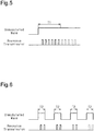
- the reception time of a trigger signal is accumulated from the starting point in time, and response transmission is restricted in accordance with the accumulated reception time. Therefore, in a case in which an unmodulated wave is transmitted continuously as shown in Fig. 5 , the transmitter controlling section 25 can shift into the restriction state when the reception time of the unmodulated wave reaches the predetermined time T1. Also, even in a case in which an unmodulated wave is transmitted intermittently as shown in Fig. 6 , the reception time T2 of the intermittently received unmodulated wave is accumulated from the starting point in time. That is, when the accumulated reception time (3 x T2) reaches the predetermined time, the transmitter controlling section 25 can shift into the restriction state. Therefore, even in a surrounding environment in which an intermittent unmodulated wave is being transmitted, the transmitter controlling section 25 can shift into the restriction state.
- the restriction state is canceled and the transmitter controlling section 25 shifts into the response state.
- the vehicle 10 travels, it is assumed that the vehicle 10 will move to another location from the location where an unmodulated wave other than a trigger signal is being transmitted. That is, it is assumed that the vehicle 10 will move to a location where it is not necessary to restrict response transmission. Since the restriction state is cancelled by traveling of the vehicle 10, it becomes possible to issue a command to the transmitter 21 with a trigger signal.
- the restriction state of the transmitter controlling section 25 is canceled, so that the transmitter controlling section 25 shifts into the response state.
- the transmitter controlling section 25 receives a trigger signal of a modulated wave
- the vehicle 10 is at a stopped state at a maintenance facility such as a dealer.
- a command may be given to transmitter 21 with a trigger signal of an unmodulated wave in order to inspect the transmitter 21.
- the restriction state can be canceled even when the transmitter 21 is in the restriction state.
- the restriction state of the transmitter controlling section 25 is canceled and the transmitter controlling section 25 shifts into the response state even when an abrupt pressure change of the tire 13 occurs.
- an abrupt pressure change of the tire 13 it is assumed that an anomaly has occurred in the wheel assembly 11.
- the tire 13 may be inspected by causing the transmitter 21 to transmit a signal with the trigger device 50. Therefore, in such a case, the transmitter controlling section 25 shifts into the response state so as to be capable of transmitting a signal in response to an unmodulated wave.
- response to an unmodulated wave can be restricted without reducing the sensitivity by restricting response transmission in the wake of the reception time of an unmodulated wave.
- the first embodiment has the following advantages.
- a transmitter according to a second embodiment will now be described. The detailed description of the components that are the same as those in the first embodiment will be omitted.
- the transmitter controlling section 25 of the second embodiment is configured to perform an accumulation process of accumulating the number of times signals are transmitted by response transmission.
- the transmitter controlling section 25 performs the accumulation process from the starting point in time and shifts into the restriction state when the number of times of signal transmission reaches a predetermined number of times.
- the "predetermined number of times" is the number of times that response transmission is performed when, for example, an unmodulated wave is received for the predetermined time of the first embodiment.
- the transmitter controlling section 25 shifts into the restriction state when response transmission is performed six times.
- the predetermined number of times is six in Figs. 5 and 6 , however, the predetermined number of times can be set to any value within a range from several times to several tens of times as necessary.
- the restriction state and the response state are switched by the same control as in the first embodiment.
- the second embodiment has the following advantage.
- (2-1) The number of times of signal transmission from the transmission circuit 26 by the response to an unmodulated wave is accumulated, and response transmission is restricted when the accumulated number of times exceeds the predetermined number of times. This prevents a signal from being transmitted continuously in response to an unmodulated wave. Therefore, it is possible to restrict an increase in power consumption of the battery 30 as compared with a case where response transmission is continuously performed as long as an unmodulated wave continues to be received. This extends the life of the battery 30 and consequently extends the life of the transmitter 21.
- the transition to the response state and the setting of the starting point in time may be performed based on any one of stopping of the vehicle 10, reception of a trigger signal of a modulated wave, and an abrupt change in pressure of the tire 13.
- the transition to the response state and the setting of the starting point in time may be performed based on any two of stopping of the vehicle 10, reception of a trigger signal of a modulated wave, and an abrupt change in pressure of the tire 13. That is, it is only necessary to perform the transition to the response state and the setting of the starting point in time based at least one of stopping of the vehicle 10, reception of a trigger signal of a modulated wave, and an abrupt change in pressure of the tire 13.
- the trigger receiving section 60 may be made unable to receive a trigger signal of a modulated wave. That is, the transmitter 21 may be compatible only with a trigger signal of an unmodulated wave (carrier detect).
- the transition to the response state and the setting of the starting point in time may be performed based on the condition that the fluctuation value per unit time of the temperature detected by the temperature sensor 23 exceeds a predetermined value. That is, the transition to the response state and the setting of the starting point in time may be performed when there is an abrupt change in temperature.
- the transmitter controlling section 25 determines whether a failure has occurred in any of the condition detecting sections such as the pressure sensor 22 and the temperature sensor 23, the transition to the response state and the setting of the starting point in time may be performed based on the detection of a failure in the condition detecting section.
- transition to the response state and the setting of the starting point in time may be performed based on traveling of the vehicle 10. Since the accumulation process is not performed while the vehicle 10 is traveling, the same advantages as in the case where the transition to the response state and the setting of the starting point in time are performed based on stopping of the vehicle 10 are obtained.
- the transmitter controlling section 25 may shift into only to the response state based on the reception of a triggered signal of a modulated wave. That is, it is not necessary to set the starting point in time based on the reception of a trigger signal of a modulated wave.
- the transmitter controlling section 25 may shift into only to the response state based on an abrupt change in pressure of the tire 13. That is, it is not necessary to set the starting point in time based on an abrupt change in pressure of the tire 13.
- the setting of the starting point in time is performed when traveling of the vehicle 10 is detected, when stopping of the vehicle 10 is detected after traveling of the vehicle 10, and when a trigger signal including a command requesting the setting of the starting point in time is received.
- the accumulation process may be performed during traveling of the vehicle 10 in addition to a stopped state of the vehicle 10.
- the traveling detecting section may be omitted.
- sensors other than the acceleration sensor 24 such as a shock sensor, an angular velocity sensor, a magnetic sensor may be used as the traveling detecting section.
- the accumulation process of the first embodiment and the accumulation process of the second embodiment may be employed together.
- the accumulation of the reception time of an unmodulated wave reaching the predetermined time in the accumulation process of the first embodiment is defined as a first condition.
- the number of times of response transmission reaching the predetermined number of times in the accumulation process in the second embodiment is defined as a second condition.
- the transmitter controlling section 25 may shift into the response state when the first condition or the second condition is met.
- the transmitter controlling section 25 may shift into the response state when both the first condition and the second condition are met.
- the frequency band of the trigger signal may be changed as necessary.
- the restriction state be a state in which response transmission is restricted as compared with the response state. In other words, it is sufficient if the power consumption of the battery 30 by response transmission is lower than that in the response state.
- the restriction state may be a state in which the frequency of transmitting the signal from the transmission circuit 26 by response transmission is less than that in the response state. In the restriction state, the output of a signal transmitted from the transmission circuit 26 by response transmission may be lower than that in the response state.
- the restriction state may be a state in which the data length of a signal transmitted from the transmission circuit 26 by response transmission is shorter than that in the response state.
- the vehicle 10 may be a motorcycle or a vehicle having five or more wheel assemblies 11.
Landscapes
- Engineering & Computer Science (AREA)
- Mechanical Engineering (AREA)
- Computer Networks & Wireless Communication (AREA)
- Physics & Mathematics (AREA)
- Electromagnetism (AREA)
- Business, Economics & Management (AREA)
- Emergency Management (AREA)
- General Physics & Mathematics (AREA)
- Measuring Fluid Pressure (AREA)
- Arrangements For Transmission Of Measured Signals (AREA)
Abstract
Description
- The present invention relates to a transmitter.
-
Patent Document 1 discloses one example of a tire condition monitoring apparatus installed in a vehicle equipped with wheel assemblies. The tire condition monitoring apparatus ofPatent Document 1 includes transmitters, which are respectively attached to the wheel assemblies, and a receiver. - The transmitter includes a pressure sensor, which detects the pressure of the tire, a transmitting section, a controlling section, which controls the transmitter, and a battery as a power source for the transmitter. The transmitting section transmits signals. The signals include a signal that contains the detection result detected by the pressure sensor.
- The transmitter also includes a trigger receiving section, which is capable of receiving a trigger signal transmitted from a trigger device. The trigger signal is transmitted from the trigger device when giving a command to the transmitter from outside. The trigger signal is transmitted to the transmitter, for example, when transmission of a signal from the transmitter at arbitrary time is desired or when the mode of the transmitter is desired to be changed. When the trigger signal is received by the trigger receiving section, the controlling section performs control in accordance with the command. When the trigger signal is received by the trigger receiving section, the controlling section performs response transmission to cause the transmitting section to transmit a signal in response to the reception of the trigger signal. This allows the trigger device to recognize that the trigger signal has been received by the trigger receiving section.
- Trigger signals are of an unmodulated wave or a modulated wave. When the transmitter is compatible with trigger signals of an unmodulated wave, the trigger receiving section receives, as trigger signals, unmodulated waves having a received signal strength indication greater than or equal to a predetermined received signal strength indication.
- Patent Document 1: Japanese Laid-Open Patent Publication No.
2014-91344 - The transmitters move with movement of the vehicle. Therefore, the surrounding environment of the transmitters changes with movement of the vehicle. Depending on the surrounding environment, unmodulated waves of the same frequency band as the trigger signal frequency band or a frequency band approximate to the trigger signal frequency band are being transmitted. When such an unmodulated wave is received by the trigger receiving section, the transmitting section transmits a signal in response to the unmodulated wave. Therefore, depending on the surrounding environment, the transmitter misidentifies an unmodulated wave different from the trigger signal as a trigger signal, so that response transmission is repeatedly performed. This may increase the power consumption of the battery and shorten the life of the transmitter.
- It is an objective of the present invention to provide a transmitter capable of limiting an increase in power consumption of a battery.
- To solve the above-described problems and in accordance with a first aspect of the present invention, a transmitter is provided that is configured to be attached to each of wheel assemblies provided in a vehicle and execute a process in accordance with a command included in a trigger signal. The transmitter includes a battery, which serves as a power source for the transmitter, a condition detecting section, which is configured to detect a condition of a tire, a trigger receiving section, which is configured to receive, as the trigger signal, an unmodulated wave having a received signal strength indication greater than or equal to a predetermined received signal strength indication, a transmitting section, which is configured to transmit a signal, and a controlling section, which is configured such that, when the trigger receiving section receives the unmodulated wave, the controlling section causes the transmitting section to transmit the signal in response to the unmodulated wave. The controlling section is configured to execute an accumulation process to accumulate reception time of the unmodulated wave from a starting point in time and to shift into a restriction state to restrict a response to the unmodulated wave when the accumulated reception time reaches a predetermined time.
- With this configuration, the response to an unmodulated wave is restricted if the accumulated time of reception of an unmodulated wave reaches the predetermined time in a case in which the vehicle is in an environment where an unmodulated wave that may be misidentified as the trigger signal is transmitted. This limits an increase in the power consumption of the battery due to responses to unmodulated waves.
- To solve the above-described problems and in accordance with a second aspect of the present invention, a transmitter is provided that is configured to be attached to each of wheel assemblies provided in a vehicle and execute a process in accordance with a command included in a trigger signal. The transmitter includes a battery, which serves as a power source for the transmitter, a condition detecting section, which is configured to detect a condition of a tire, a trigger receiving section, which is configured to receive, as the trigger signal, an unmodulated wave having a received signal strength indication greater than or equal to a predetermined received signal strength indication, a transmitting section, which is configured to transmit a signal, and a controlling section, which is configured such that, when the trigger receiving section receives the unmodulated wave, the controlling section causes the transmitting section to transmit the signal in response to the unmodulated wave. The controlling section is configured to execute an accumulation process to accumulate a number of times of the signal transmitted from the transmitting section from a starting point in time in response to the unmodulated wave and to shift into a restriction state to restrict a response to the unmodulated wave when the accumulated number of times reaches a predetermined number of times.
- With this configuration, the response to an unmodulated wave is restricted when the number of times of transmission of a signal transmitted in response to an unmodulated wave reaches the predetermined number of times in a case in which the vehicle is in an environment where an unmodulated wave that may be misidentified as the trigger signal is transmitted. This limits an increase in the power consumption of the battery due to responses to unmodulated waves.
- The above-described transmitter includes a traveling detecting section, which detects traveling and stopping of the vehicle. The controlling section may be configured to execute the accumulation process when the vehicle is at a stopped state.
- When the vehicle is traveling, the surrounding environment of the vehicle changes as the vehicle moves. Therefore, when the vehicle is traveling, the transmitter is unlikely to continue to receive an unmodulated wave different from the trigger signal over a long period of time. In contrast, when the vehicle is at a stopped state, the transmitter may continue to receive an unmodulated wave different from the trigger signal over a long period of time. By carrying out the accumulation process when the vehicle is at a stopped state, the transition to the restriction state is properly performed.
- The above-described transmitter includes a traveling detecting section, which detects traveling and stopping of the vehicle. The controlling section may be configured to execute, based on detection of stopping of the vehicle by the traveling detecting section, transition to a response state, in which response to the unmodulated wave is not restricted, and setting of the starting point in time.
- With this configuration, it is possible to cause the controlling section to shift into the response state in the wake of stopping of the vehicle.
- In the above-described transmitter, the trigger receiving section may be capable of receiving a trigger signal of a modulated wave, and the controlling section may be configured to execute, based on reception of the trigger signal of a modulated wave by the trigger receiving section, transition to a response state, in which response to the unmodulated wave is not restricted.
- With this configuration, it is possible to cause the controlling section to shift into the response state at arbitrary time by using the trigger device capable of transmitting a trigger signal of a modulated wave.
- In the above-described transmitter, the condition detecting section may include a pressure sensor that detects a pressure of the tire, and the controlling section may be configured to execute, based on a condition in which a fluctuation value per unit time of a pressure detected by the pressure sensor exceeds a predetermined value, transition to a response state, in which response to the unmodulated wave is not restricted.
- In a case where the fluctuation value per unit time of the pressure of the tire exceeds the predetermined value, the tire may be inspected using a trigger device. When the fluctuation value per unit time of the pressure of the tire exceeds the predetermined value, the controlling section shifts into the response state. Thus, it is possible to suppress the occurrence of a situation in which it is impossible to inspect the tire although the fluctuation value per unit time of the pressure of the tire has exceeded the predetermined value.
- The present invention limits an increase in the power consumption of a battery.
-
-
Fig. 1 is a schematic diagram of a tire condition monitoring apparatus and a trigger device. -
Fig. 2 is a schematic diagram of a transmitter and the trigger device. -
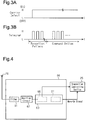
Fig. 3A is a schematic diagram showing a trigger signal of an unmodulated wave. -
Fig. 3B is a schematic diagram showing a trigger signal of a modulated wave. -
Fig. 4 is a schematic diagram showing the trigger receiving section. -
Fig. 5 is a diagram showing the relationship between an unmodulated wave that is transmitted continuously and response transmission. -
Fig. 6 is a diagram showing the relationship between an unmodulated wave that is transmitted intermittently and response transmission. - A transmitter according to a first embodiment will now be described.
- As shown in
Fig. 1 , a tirecondition monitoring apparatus 20 includestransmitters 21 and areceiver 40. Eachtransmitter 21 is configured to be attached to one of the fourwheel assemblies 11 of avehicle 10. Thereceiver 40 is installed in thevehicle 10. Each of thewheel assemblies 11 includes awheel 12 and atire 13 attached to thewheel 12. Eachtransmitter 21 is of a type that is fixed to the tire valve, thewheel 12, or thetire 13. - The
transmitter 21 is attached to thewheel assembly 11 so as to be arranged in the inner space of thetire 13. Thetransmitter 21 detects the condition of the correspondingtire 13, for example, the air pressure and internal temperature of thetire 13 and wirelessly transmits a signal including the detection results to thereceiver 40. The tirecondition monitoring apparatus 20 monitors the conditions of thetires 13 by receiving signals transmitted from thetransmitters 21 at thereceiver 40. - As shown in
Fig. 2 , thetransmitter 21 includes apressure sensor 22, atemperature sensor 23, anacceleration sensor 24, atransmitter controlling section 25, atransmission circuit 26, atransmission antenna 28, areception antenna 29, abattery 30, and atrigger receiving section 60. Thebattery 30 serves as a power source for thetransmitter 21. - The
pressure sensor 22 detects the pressure (air pressure) of the correspondingtire 13. Thepressure sensor 22 outputs the detection result to thetransmitter controlling section 25. Thetemperature sensor 23 detects the temperature inside the correspondingtire 13. Thetemperature sensor 23 outputs the detection result to thetransmitter controlling section 25. - The
acceleration sensor 24 rotates integrally with thewheel assembly 11 to detect the centrifugal acceleration acting on thewheel assembly 11. Theacceleration sensor 24 outputs the detection result to thetransmitter controlling section 25. In the present embodiment, thepressure sensor 22, thetemperature sensor 23, and theacceleration sensor 24 constitute a condition detecting section that detects the condition of thetire 13. - The
transmitter controlling section 25, which serves as a controlling section, is composed of circuitry such as a microcomputer including aCPU 25a and amemory section 25b (such as a RAM and a ROM). Thetransmitter controlling section 25 includes a timing function. An ID code, which is identification information unique to eachtransmitter 21, is registered in thememory section 25b. Thememory section 25b stores various programs for controlling thetransmitter 21. - The
transmitter controlling section 25 may include dedicated hardware (application specific integrated circuit: ASIC) that executes at least part of various processes. That is, thetransmitter controlling section 25 may be circuitry including 1) one or more processors that operate according to a computer program (software), 2) one or more dedicated hardware circuits such as an ASIC, or 3) a combination thereof. The processor includes a CPU and memory such as a RAM and ROM. The memory stores program codes or instructions configured to cause the CPU to execute processes. The memory, or computer readable medium, includes any type of medium that is accessible by general-purpose computers and dedicated computers. - The
transmitter controlling section 25 generates data and outputs it to thetransmission circuit 26. Thetransmission circuit 26, which functions as a transmitting section, modulates the data from thetransmitter controlling section 25 to generate a signal (RF signal), and transmits the signal through thetransmission antenna 28. For example, thetransmitter controlling section 25 generates data including the ID code and the tire condition, which includes the detection result of thepressure sensor 22 and the detection result of thetemperature sensor 23. Thetransmitter controlling section 25 transmits a data signal, which includes the data. - The
transmitter controlling section 25 determines whether thevehicle 10 is traveling based on the detection result of theacceleration sensor 24. The centrifugal acceleration acting on thewheel assembly 11 increases as the speed of thevehicle 10 increases. Thetransmitter controlling section 25 determines that thevehicle 10 is traveling when the centrifugal acceleration detected by theacceleration sensor 24 exceeds a preset threshold value. The threshold value is set to a value greater than the centrifugal acceleration detected when thevehicle 10 is at a stopped state. In the present embodiment, theacceleration sensor 24 functions as a Traveling detecting section. - As shown in
Fig. 1 , thereceiver 40 includes areceiver controlling section 41, areceiver reception circuit 42, and areception antenna 43. Awarning device 44 is connected to thereceiver controlling section 41. Thereceiver controlling section 41 is composed of a microcomputer including a receiver CPU 41a and areceiver memory section 41b (such as a ROM and a RAM). Thereceiver reception circuit 42 demodulates data signals transmitted from thetransmitters 21 and received via thereception antenna 43 and delivers the demodulated signals to thereceiver controlling section 41. - The
receiver controlling section 41 obtains the condition of thetire 13 based on the data included in the data signal transmitted from thetransmitter 21. When an anomaly occurs in any of thetires 13, thereceiver controlling section 41 performs notification by using the warning device (notification device) 44. For example, thewarning device 44 may be a device that notifies the user of the anomaly with sound or illumination or blinking of light. Also, thereceiver controlling section 41 may display the condition of thetire 13 on the display unit that the occupants of thevehicle 10 can visually recognize. - The
transmitter 21 can perform various actions in response to a trigger signal transmitted from atrigger device 50. The trigger signal may be, for example, a signal for requesting thetransmitter 21 to transmit a data signal, a signal for requesting thetransmitter 21 to change the transmission interval of data signals, a signal for requesting thetransmitter 21 to register an ID code in thememory section 25b, and a signal for updating the software of thetransmitter 21. Thetrigger device 50 is found, for example, at maintenance facilities such as dealers and production bases such as a factory that manufactures thetransmitters 21 and a factory where thetransmitters 21 are attached to thewheel assemblies 11. - Hereinafter, the
trigger device 50 and thetrigger receiving section 60 of thetransmitter 21 will be described. - As shown in
Figs. 1 and 2 , thetrigger device 50 includesmultiple manipulation sections 51, a triggerdevice transmission circuit 52, a triggerdevice reception circuit 53, adisplay 54, a triggerdevice controlling section 55, a triggerdevice transmission antenna 56, and a triggerdevice reception antenna 57. Themanipulation sections 51 are manipulated by the user. The user of thetrigger device 50 can specify operations that thetransmitter 21 is requested to do by operating themanipulation sections 51. Thetrigger device 50 transmits a trigger signal requesting an operation corresponding to the manipulation of themanipulation sections 51. - The
manipulation sections 51 are connected to the triggerdevice controlling section 55. The triggerdevice controlling section 55 generates data in response to manipulation of themanipulation sections 51. This data includes a command option that is a command to thetransmitter 21. - The trigger
device controlling section 55 outputs the generated data to the triggerdevice transmission circuit 52. The triggerdevice transmission circuit 52 generates a trigger signal corresponding to the data. The trigger signal is transmitted from the triggerdevice transmission antenna 56. - The trigger
device reception circuit 53 receives a data signal (RF signal) transmitted (returned) from thetransmitter 21 via the triggerdevice reception antenna 57. The triggerdevice reception circuit 53 demodulates the data signal and outputs it to the triggerdevice controlling section 55. - The types of the
trigger device 50 include the one that employs carrier detect and the one that employs telegram as the communication method. The carrier detect is a method that uses an unmodulated wave as the trigger signal. The telegram is a method that uses a modulated wave as the trigger signal. - As shown in
Fig. 3A , when thetrigger device 50 employs the carrier detect, an unmodulated wave in an LF band (for example, 125 kHz band) is used as the trigger signal. - As shown in
Fig. 3B , when thetrigger device 50 employs the telegram, a modulated wave in an LF band (for example, 125 kHz band) is used as the trigger signal. A signal obtained by modulating a digital signal obtained by encoding data of 73 bits in total is used as the trigger signal. The encoding is executed, for example, by Manchester code. The modulation is executed, for example, with amplitude shift keying (ASK). - The above-mentioned 73-bit data includes a command option and a reception pattern (pattern including a preamble, a synchronization bit, and a wake-up ID) for causing the
trigger receiving section 60 to recognize that it is a trigger signal. The reception pattern is defined by the telegram and is always the same. The command option differs depending on the action thetransmitter 21 is requested to perform. The command option can request thetransmitter 21 to perform the action corresponding to themanipulation section 51. The above data is not limited to 73-bit data but may have other data lengths. - Next, the
trigger receiving section 60 of thetransmitter 21 will be described. - As shown in
Fig. 4 , thetrigger receiving section 60 includes afilter 61, which passes only a signal of a specific frequency band out of signals arriving at thereception antenna 29, anamplifier circuit 62, which amplifies a signal passing through thefilter 61, and a determination section (determination circuit) 63, which determines whether the amplified signal is a trigger signal. - The
filter 61 removes noise by permitting passage of signals of, for example, an LF band (for example, a 125 kHz band). Theamplifier circuit 62 is composed of, for example, an amplifier of which the gain is variable or multiple amplifiers having different gains. - The
trigger receiving section 60 of the present embodiment is capable of receiving both of the trigger signal of an unmodulated wave and a trigger signal of a modulated wave. Thedetermination section 63 includes a first determination section 66 (first determination function), which determines whether a received signal is a trigger signal of an unmodulated wave, and a second determination section 67 (second determination function), which determines whether a received signal is a trigger signal of a modulated wave. - The
first determination section 66 determines whether the received signal strength indication (RSSI) [dBm] of an unmodulated wave is greater than or equal to a predetermined RSSI. Thefirst determination section 66 determines that an unmodulated wave the RSSI of which is greater than or equal to the predetermined RSSI is a trigger signal of an unmodulated wave. The predetermined RSSI is set in advance according to, for example, the output of thetrigger device 50. - The
second determination section 67 determines whether the reception pattern included in a signal matches with a preset reception pattern (reception pattern defined by the telegram). Thesecond determination section 67 determines that a signal is a trigger signal when the reception pattern included in that signal matches with a preset reception pattern. Thedetermination section 63 alternately repeats the determination by thefirst determination section 66 and the determination by thesecond determination section 67. Accordingly, thedetermination section 63 is capable of receiving both of a trigger signal of an unmodulated wave and a trigger signal of a modulated wave. - The
determination section 63 has a function of sending a wake-up signal to thetransmitter controlling section 25. Since there are only a few opportunities to receive trigger signals, thetransmitter controlling section 25 turns off the reception function until receiving a wake-up signal to save power. Thetransmitter controlling section 25 acquires a trigger signal upon reception of the wake-up signal. As a result, thetransmitter controlling section 25 recognizes the action requested by thetrigger device 50. "Reception" in thetrigger receiving section 60 refers to causing thetransmitter controlling section 25 to receive the data included in a trigger signal. - When the
trigger receiving section 60 receives a trigger signal, thetransmitter controlling section 25 performs response transmission to cause thetransmission circuit 26 to transmit a signal in response to the reception of the trigger signal. The signal transmitted by response transmission is a signal for informing thetrigger device 50 that a trigger signal has been received. If response transmission is not performed, it can be said that thetransmitter 21 cannot perform any operation in response to the trigger signal. By receiving a signal transmitted by response transmission, thetrigger device 50 can recognize that thetransmitter 21 has received the trigger signal. - The
transmitter controlling section 25 can be in a response state and a restriction state as reception states when an unmodulated wave is received by thetrigger receiving section 60. The response state is a state in which a response to an unmodulated wave is not restricted, and a signal is transmitted in response to an unmodulated wave. The restriction state is a state in which the response to unmodulated waves is restricted. In the present embodiment, the restriction state is a state in which response to an unmodulated wave is not performed. In either state, the response to a trigger signal of modulated wave is performed. - The
transmitter controlling section 25 switches between the response state and the restriction state according to whether a predefined condition is met. The switching between the response state and the restriction state will be described below. - The
transmitter controlling section 25 executes an accumulation process to measure reception time of an unmodulated wave from a starting point in time and accumulates the reception time. When an unmodulated wave continues being received, the accumulation of the reception time of the unmodulated wave is the duration of that reception. When an unmodulated wave is received intermittently, the accumulation is the accumulated time of the time when the unmodulated wave is received. - The
transmitter controlling section 25 performs the accumulation process from the starting point in time and shifts into the restriction state when the accumulated reception time reaches a predetermined time. The "predetermined time" is, for example, time during which it can be determined that an unmodulated wave is not the trigger signal. When a trigger signal is transmitted bytrigger device 50, the transmission of the trigger signal is stopped if response transmission from thetransmitter 21 is received or when response transmission cannot be received for a period longer than time that is set in advance. By setting the predetermined time to be longer than the time that is set in advance, it can be determined that the unmodulated wave received for a period exceeding the predetermined time is not a trigger signal. - The
transmitter controlling section 25 executes the accumulation process when the centrifugal acceleration detected by theacceleration sensor 24 is lower than the threshold value. As a result, the accumulation process is executed while thevehicle 10 is determined to be at a stopped state by thetransmitter controlling section 25. - In the present embodiment, the setting of the starting point in time is performed based on stopping of the
vehicle 10, reception of the trigger signal of a modulated wave, and abrupt pressure change of thetire 13. The setting of the starting point in time can be regarded as resetting of the reception time of an unmodulated wave, which has been accumulated in the accumulation process. Since the starting point in time is set, the restriction state will be canceled if the reception state of thetransmitter controlling section 25 is the restriction state. When the restriction state is canceled, thetransmitter controlling section 25 shifts into the response state. When the starting point in time is set, the response state will be maintained if the reception state of thetransmitter controlling section 25 is the response state. - The
transmitter controlling section 25 sets the starting point in time based on the detection of stopping of thevehicle 10. Specifically, thetransmitter controlling section 25 sets the starting point in time when the centrifugal acceleration has changed from a value greater than or equal to the threshold value to a value below the threshold value. Thetransmitter controlling section 25 may set the starting point in time to a point in time at which stopping of thevehicle 10 is detected. Alternatively, thetransmitter controlling section 25 may set the starting point in time to a point in time a few seconds to several minutes after stopping of thevehicle 10 is detected. That is, when the starting point in time is set based on detection of stopping of thevehicle 10, the starting point in time is set within an allowable range from the point in time when thevehicle 10 is stopped. Also, upon detecting stopping of thevehicle 10, thetransmitter controlling section 25 shifts into the response state. This allows thetransmitter 21 to respond to a trigger signal of an unmodulated wave. - When receiving a trigger signal of a modulated wave, the
transmitter controlling section 25 sets the starting point in time based on the reception. The trigger signal of a modulated wave may be one that requests setting of the starting point in time or one that requests transmission of a signal including data indicating the state of thetire 13. That is, the starting point in time may be set by a dedicated command option. Alternatively, the starting point in time may be set when a trigger signal of a modulated wave is received irrespective of the command option. Thetransmitter controlling section 25 may set the starting point in time to a point in time at which a trigger signal is received or a point in time a few seconds after receiving a trigger signal. That is, when the starting point in time is set based on the reception of a trigger signal of a modulated wave, the starting point in time is set within an allowable range from the point in time when thetrigger receiving section 60 receives a trigger signal. Also, upon reception of a trigger signal of a modulated wave, thetransmitter controlling section 25 shifts into the response state. - When an abrupt change in pressure occurs in the
tire 13, thetransmitter controlling section 25 sets the starting point in time based on that pressure change. Thetransmitter controlling section 25 determines that the pressure of thetire 13 has changed abruptly when the fluctuation value per unit time of the pressure detected by thepressure sensor 22 exceeds a predetermined value. The predetermined value is greater than the pressure of thetire 13, which naturally decreases with the traveling of thevehicle 10 and the passage of time. Thetransmitter controlling section 25 may set the starting point in time to a point in time when an abrupt change in pressure occurs in thetire 13. Alternatively, thetransmitter controlling section 25 may set the starting point in time to a point in time a few seconds to several minutes after the occurrence of such an abrupt change in pressure of thetire 13. That is, when the starting point in time is set based on an abrupt change in pressure of thetire 13, the starting point in time is set within an allowable range from the point in time when thetransmitter controlling section 25 detects the abrupt change in pressure. Also, when an abrupt pressure change of thetire 13 occurs, thetransmitter controlling section 25 enters into the response state. - An operation of the
transmitter 21 of the present embodiment will now be described. - It is now assumed that the
vehicle 10 travels and stops. Depending on the surrounding environment of thevehicle 10, an unmodulated wave in the same frequency band as a trigger signal or in a frequency band approximate to the trigger signal may be transmitted continuously. For example, in a parking lot or on a freeway, there are cases where LF signals are output in or about the 125 kHz band in order to detect thevehicle 10. - When an unmodulated wave other than a trigger signal is misidentified as a trigger signal by the
trigger receiving section 60, thetransmitter controlling section 25 performs response transmission in response to the unmodulated wave. While the unmodulated wave continues to be received, a signal is transmitted from thetransmission circuit 26 intermittently through response transmission. Thetransmitter controlling section 25 shifts into the restriction state when the reception time of the unmodulated wave reaches the predetermined time. In the restriction state, thetransmitter controlling section 25 does not perform response transmission even when receiving an unmodulated wave. - It is now assumed that a transmitter is used that measures the time during which it continuously receives an unmodulated wave and shifts into the restriction state when the measured time exceeds the predetermined time. In this case, as shown in
Fig. 5 , the transmitter controlling section can shift into the restriction state when receiving the continuously transmitted unmodulated wave. However, as shown inFig. 6 , when an intermittently transmitted unmodulated wave is received, the time for which the unmodulated wave has been received is reset by the interruption of the unmodulated wave. Therefore, in a surrounding environment in which an unmodulated wave is transmitted intermittently, response transmission by the transmitter controlling section may be repeatedly performed. - In the present embodiment, the reception time of a trigger signal is accumulated from the starting point in time, and response transmission is restricted in accordance with the accumulated reception time. Therefore, in a case in which an unmodulated wave is transmitted continuously as shown in
Fig. 5 , thetransmitter controlling section 25 can shift into the restriction state when the reception time of the unmodulated wave reaches the predetermined time T1. Also, even in a case in which an unmodulated wave is transmitted intermittently as shown inFig. 6 , the reception time T2 of the intermittently received unmodulated wave is accumulated from the starting point in time. That is, when the accumulated reception time (3 x T2) reaches the predetermined time, thetransmitter controlling section 25 can shift into the restriction state. Therefore, even in a surrounding environment in which an intermittent unmodulated wave is being transmitted, thetransmitter controlling section 25 can shift into the restriction state. - When the
vehicle 10 travels, the restriction state is canceled and thetransmitter controlling section 25 shifts into the response state. When thevehicle 10 travels, it is assumed that thevehicle 10 will move to another location from the location where an unmodulated wave other than a trigger signal is being transmitted. That is, it is assumed that thevehicle 10 will move to a location where it is not necessary to restrict response transmission. Since the restriction state is cancelled by traveling of thevehicle 10, it becomes possible to issue a command to thetransmitter 21 with a trigger signal. - Also, even if the
transmitter controlling section 25 receives a trigger signal of a modulated wave, the restriction state of thetransmitter controlling section 25 is canceled, so that thetransmitter controlling section 25 shifts into the response state. When thetransmitter controlling section 25 receives a trigger signal of a modulated wave, it is assumed that thevehicle 10 is at a stopped state at a maintenance facility such as a dealer. In this case, a command may be given totransmitter 21 with a trigger signal of an unmodulated wave in order to inspect thetransmitter 21. By transmitting a trigger signal of a modulated wave using thetrigger device 50 compatible with telegram, the restriction state can be canceled even when thetransmitter 21 is in the restriction state. - The restriction state of the
transmitter controlling section 25 is canceled and thetransmitter controlling section 25 shifts into the response state even when an abrupt pressure change of thetire 13 occurs. When an abrupt pressure change of thetire 13 occurs, it is assumed that an anomaly has occurred in thewheel assembly 11. In this case, thetire 13 may be inspected by causing thetransmitter 21 to transmit a signal with thetrigger device 50. Therefore, in such a case, thetransmitter controlling section 25 shifts into the response state so as to be capable of transmitting a signal in response to an unmodulated wave. - It is also conceivable to restrict response transmission to an unmodulated wave by reducing the sensitivity to unmodulated waves. However, in a case in which one
trigger receiving section 60 is compatible with both a trigger signal of a modulated wave and a trigger signal of an unmodulated wave as in the present embodiment, it is difficult to largely differentiate between the sensitivity to a modulated wave and the sensitivity to an unmodulated wave. Accordingly, reduction in the sensitivity to an unmodulated wave will reduce the sensitivity to a modulated wave. It is possible determine whether a modulated wave is a trigger signal through matching of the reception patterns. For this reason, it is unlikely that a modulated wave other than a trigger signal will be misidentified as a trigger signal, and it is unnecessary to reduce the sensitivity. If the sensitivity to a modulated wave is reduced together with the sensitivity to an unmodulated wave, it will be necessary to increase the output of thetrigger device 50 compatible with telegram and operate thetrigger device 50 in proximity to thetransmitter 21. - In contrast, in the present embodiment, response to an unmodulated wave can be restricted without reducing the sensitivity by restricting response transmission in the wake of the reception time of an unmodulated wave.
- Accordingly, the first embodiment has the following advantages.
- (1-1) The
transmitter controlling section 25 accumulates the reception time for which an unmodulated wave is received and restricts response transmission when the accumulated reception time reaches the predetermined time. This prevents a signal from being transmitted continuously in response to an unmodulated wave. Therefore, it is possible to restrict an increase in power consumption of thebattery 30 as compared with a case where response transmission is continuously performed as long as an unmodulated wave continues to be received. This extends the life of thebattery 30 and consequently extends the life of thetransmitter 21. - (1-2) The accumulation process is performed while the
vehicle 10 is at a stopped state. When thevehicle 10 is traveling, the surrounding environment of thevehicle 10 changes as thevehicle 10 moves. Therefore, when thevehicle 10 is traveling, thetransmitter 21 is unlikely to continue to receive an unmodulated wave different from the trigger signal over a long period of time. In contrast, in a case in which thevehicle 10 is at a stopped state, there is a risk that thetransmitter 21 will be exposed, for an extended period of time, to an environment where an unmodulated wave that can be misidentified as a trigger signal continues to be transmitted. In this case, response transmission may be performed over a long period of time. By carrying out the accumulation process when thevehicle 10 is at a stopped state, the transition to the restriction state is properly performed. - (1-3) The
transmitter controlling section 25 shifts into the response state in the wake of stopping of thevehicle 10. When giving a command to thetransmitter 21, thetrigger device 50 is caused to transmit a trigger signal with thevehicle 10 at a stopped state. Accordingly, thetransmitter controlling section 25 shifts into the response state in a situation in which thetrigger device 50 is used. This allows thetransmitter controlling section 25 to perform an operation in response to a command from thetrigger device 50.
Also, thetransmitter controlling section 25 sets the starting point in time in the wake of stopping of thevehicle 10. That is, each time thevehicle 10 moves, the accumulation of the reception time of an unmodulated wave is reset. Therefore, thetransmitter controlling section 25 can determine whether to shift into the restriction state in accordance with the surrounding environment of thevehicle 10. - (1-4) The
transmitter controlling section 25 shifts into the response state based on the reception of a triggered signal of a modulated wave. Thus, it is possible to cause thetransmitter controlling section 25 to shift into the response state at arbitrary time by using thetrigger device 50 capable of transmitting a trigger signal of a modulated wave. - (1-5) The
transmitter controlling section 25 shifts into the response state based on an abrupt change in the pressure of thetire 13. When an abrupt change in pressure occurs, thetransmitter controlling section 25 shifts into the response state, so that thetire 13 can be inspected using thetrigger device 50. - A transmitter according to a second embodiment will now be described. The detailed description of the components that are the same as those in the first embodiment will be omitted.
- The
transmitter controlling section 25 of the second embodiment is configured to perform an accumulation process of accumulating the number of times signals are transmitted by response transmission. Thetransmitter controlling section 25 performs the accumulation process from the starting point in time and shifts into the restriction state when the number of times of signal transmission reaches a predetermined number of times. The "predetermined number of times" is the number of times that response transmission is performed when, for example, an unmodulated wave is received for the predetermined time of the first embodiment. - In the example shown in
Figs. 5 and 6 , thetransmitter controlling section 25 shifts into the restriction state when response transmission is performed six times. For the purpose of illustration, the predetermined number of times is six inFigs. 5 and 6 , however, the predetermined number of times can be set to any value within a range from several times to several tens of times as necessary. - There is a proportional relationship between the reception time and the number of times a signal is transmitted by response transmission. Therefore, even when the number of times of reception transmission is accumulated by the accumulation process, the same advantages as those of the first embodiment are obtained.
- In the second embodiment, the restriction state and the response state are switched by the same control as in the first embodiment.
- Accordingly, in addition to the advantages (1-2) to (1-5) of the first embodiment, the second embodiment has the following advantage.
(2-1) The number of times of signal transmission from thetransmission circuit 26 by the response to an unmodulated wave is accumulated, and response transmission is restricted when the accumulated number of times exceeds the predetermined number of times. This prevents a signal from being transmitted continuously in response to an unmodulated wave. Therefore, it is possible to restrict an increase in power consumption of thebattery 30 as compared with a case where response transmission is continuously performed as long as an unmodulated wave continues to be received. This extends the life of thebattery 30 and consequently extends the life of thetransmitter 21. - The embodiments may be modified as follows.
- In each of the above-described embodiments, the transition to the response state and the setting of the starting point in time may be performed based on any one of stopping of the
vehicle 10, reception of a trigger signal of a modulated wave, and an abrupt change in pressure of thetire 13. Also, the transition to the response state and the setting of the starting point in time may be performed based on any two of stopping of thevehicle 10, reception of a trigger signal of a modulated wave, and an abrupt change in pressure of thetire 13. That is, it is only necessary to perform the transition to the response state and the setting of the starting point in time based at least one of stopping of thevehicle 10, reception of a trigger signal of a modulated wave, and an abrupt change in pressure of thetire 13. - If the transition to the response state and the setting of the starting point in time are not performed based on reception of a trigger signal of a modulated wave, the
trigger receiving section 60 may be made unable to receive a trigger signal of a modulated wave. That is, thetransmitter 21 may be compatible only with a trigger signal of an unmodulated wave (carrier detect). - The transition to the response state and the setting of the starting point in time may be performed based on the condition that the fluctuation value per unit time of the temperature detected by the
temperature sensor 23 exceeds a predetermined value. That is, the transition to the response state and the setting of the starting point in time may be performed when there is an abrupt change in temperature. In addition, in a case in which thetransmitter controlling section 25 determines whether a failure has occurred in any of the condition detecting sections such as thepressure sensor 22 and thetemperature sensor 23, the transition to the response state and the setting of the starting point in time may be performed based on the detection of a failure in the condition detecting section. - Further, the transition to the response state and the setting of the starting point in time may be performed based on traveling of the
vehicle 10. Since the accumulation process is not performed while thevehicle 10 is traveling, the same advantages as in the case where the transition to the response state and the setting of the starting point in time are performed based on stopping of thevehicle 10 are obtained. - In each of the above-described embodiments, the
transmitter controlling section 25 may shift into only to the response state based on the reception of a triggered signal of a modulated wave. That is, it is not necessary to set the starting point in time based on the reception of a trigger signal of a modulated wave. Likewise, in each of the above-described embodiments, thetransmitter controlling section 25 may shift into only to the response state based on an abrupt change in pressure of thetire 13. That is, it is not necessary to set the starting point in time based on an abrupt change in pressure of thetire 13. In these cases, the setting of the starting point in time is performed when traveling of thevehicle 10 is detected, when stopping of thevehicle 10 is detected after traveling of thevehicle 10, and when a trigger signal including a command requesting the setting of the starting point in time is received. - In each of the above-described embodiments, the accumulation process may be performed during traveling of the
vehicle 10 in addition to a stopped state of thevehicle 10. In this case, the traveling detecting section may be omitted. - In each of the above-described embodiments, sensors other than the
acceleration sensor 24 such as a shock sensor, an angular velocity sensor, a magnetic sensor may be used as the traveling detecting section. - The accumulation process of the first embodiment and the accumulation process of the second embodiment may be employed together. The accumulation of the reception time of an unmodulated wave reaching the predetermined time in the accumulation process of the first embodiment is defined as a first condition. Also, the number of times of response transmission reaching the predetermined number of times in the accumulation process in the second embodiment is defined as a second condition. In this case, the
transmitter controlling section 25 may shift into the response state when the first condition or the second condition is met. Alternatively, thetransmitter controlling section 25 may shift into the response state when both the first condition and the second condition are met. - In each of the above-described embodiments, it is only necessary to provide, as the condition detecting section, at least one of the
pressure sensor 22, thetemperature sensor 23, and theacceleration sensor 24. - In each of the above-described embodiments, the frequency band of the trigger signal may be changed as necessary.
- In each of the above-described embodiments, it is only necessary that the restriction state be a state in which response transmission is restricted as compared with the response state. In other words, it is sufficient if the power consumption of the
battery 30 by response transmission is lower than that in the response state. For example, the restriction state may be a state in which the frequency of transmitting the signal from thetransmission circuit 26 by response transmission is less than that in the response state. In the restriction state, the output of a signal transmitted from thetransmission circuit 26 by response transmission may be lower than that in the response state. The restriction state may be a state in which the data length of a signal transmitted from thetransmission circuit 26 by response transmission is shorter than that in the response state. - In each of the above-described embodiments, the
vehicle 10 may be a motorcycle or a vehicle having five ormore wheel assemblies 11. - 10...Vehicle; 11...Wheel Assembly; 13...Tire; 21...Transmitter; 22...Pressure Sensor (Condition Detecting Section); 23...Temperature Sensor (Condition Detecting Section); 24...Acceleration Sensor (Condition Detecting Section and Traveling detecting section); 25...Transmitter Controlling Section (Controlling section); 26...Transmission Circuit (Transmitting Section); 30...Battery; 50...Trigger Device; 60...Trigger Receiving Section.
Claims (6)
- A transmitter configured to be attached to each of wheel assemblies provided in a vehicle and execute a process in accordance with a command included in a trigger signal, the transmitter comprising:a battery, which serves as a power source for the transmitter;a condition detecting section, which is configured to detect a condition of a tire;a trigger receiving section, which is configured to receive, as the trigger signal, an unmodulated wave having a received signal strength indication greater than or equal to a predetermined received signal strength indication;a transmitting section, which is configured to transmit a signal; anda controlling section, which is configured such that, when the trigger receiving section receives the unmodulated wave, the controlling section causes the transmitting section to transmit the signal in response to the unmodulated wave,wherein the controlling section is configured toexecute an accumulation process to accumulate reception time of the unmodulated wave from a starting point in time, andshift into a restriction state to restrict a response to the unmodulated wave when the accumulated reception time reaches a predetermined time.
- A transmitter configured to be attached to each of wheel assemblies provided in a vehicle and execute a process in accordance with a command included in a trigger signal, the transmitter comprising:a battery, which serves as a power source for the transmitter;a condition detecting section, which is configured to detect a condition of a tire;a trigger receiving section, which is configured to receive, as the trigger signal, an unmodulated wave having a received signal strength indication greater than or equal to a predetermined received signal strength indication;a transmitting section, which is configured to transmit a signal; anda controlling section, which is configured such that, when the trigger receiving section receives the unmodulated wave, the controlling section causes the transmitting section to transmit the signal in response to the unmodulated wave,wherein the controlling section is configured toexecute an accumulation process to accumulate a number of times of the signal transmitted from the transmitting section from a starting point in time in response to the unmodulated wave, andshift into a restriction state to restrict a response to the unmodulated wave when the accumulated number of times reaches a predetermined number of times.
- The transmitter according to claim 1 or 2, further comprising a traveling detecting section, which detects traveling and stopping of the vehicle,
wherein the controlling section is configured to execute the accumulation process when the vehicle is at a stopped state. - The transmitter according to any one of claims 1 to 3, further comprising a traveling detecting section, which detects traveling and stopping of the vehicle,
wherein the controlling section is configured to execute, based on detection of stopping of the vehicle by the traveling detecting section, transition to a response state, in which response to the unmodulated wave is not restricted, and setting of the starting point in time. - The transmitter according to any one of claims 1 to 4, wherein
the trigger receiving section is capable of receiving a trigger signal of a modulated wave, and
the controlling section is configured to execute, based on reception of the trigger signal of a modulated wave by the trigger receiving section, transition to a response state, in which response to the unmodulated wave is not restricted. - The transmitter according to any one of claims 1 to 5, wherein
the condition detecting section includes a pressure sensor that detects a pressure of the tire, and
the controlling section is configured to execute, based on a condition in which a fluctuation value per unit time of a pressure detected by the pressure sensor exceeds a predetermined value, transition to a response state, in which response to the unmodulated wave is not restricted.
Applications Claiming Priority (1)
| Application Number | Priority Date | Filing Date | Title |
|---|---|---|---|
| PCT/JP2017/043695 WO2019111329A1 (en) | 2017-12-05 | 2017-12-05 | Transmitter |
Publications (3)
| Publication Number | Publication Date |
|---|---|
| EP3521070A1 true EP3521070A1 (en) | 2019-08-07 |
| EP3521070A4 EP3521070A4 (en) | 2020-01-08 |
| EP3521070B1 EP3521070B1 (en) | 2022-03-30 |
Family
ID=66750847
Family Applications (1)
| Application Number | Title | Priority Date | Filing Date |
|---|---|---|---|
| EP17928824.6A Active EP3521070B1 (en) | 2017-12-05 | 2017-12-05 | Transmitter |
Country Status (5)
| Country | Link |
|---|---|
| US (1) | US11724552B2 (en) |
| EP (1) | EP3521070B1 (en) |
| JP (1) | JP6831000B2 (en) |
| CN (1) | CN110121436B (en) |
| WO (1) | WO2019111329A1 (en) |
Families Citing this family (1)
| Publication number | Priority date | Publication date | Assignee | Title |
|---|---|---|---|---|
| WO2019111330A1 (en) * | 2017-12-05 | 2019-06-13 | 太平洋工業 株式会社 | Transmitter and tire state monitoring device |
Family Cites Families (17)
| Publication number | Priority date | Publication date | Assignee | Title |
|---|---|---|---|---|
| JP2996831B2 (en) | 1993-04-14 | 2000-01-11 | 株式会社豊田中央研究所 | Transponder for mobile identification device |
| JPH11334328A (en) | 1998-05-29 | 1999-12-07 | Pacific Ind Co Ltd | Tire inflation pressure warning system |
| US6340929B1 (en) * | 1998-11-19 | 2002-01-22 | Pacific Industrial Co., Ltd | Transmitter and external controller of tire inflation pressure monitor |
| US6904796B2 (en) | 2003-04-21 | 2005-06-14 | G-5 Electronics, Llc | Remote tire monitoring systems tool |
| JP2005309958A (en) * | 2004-04-23 | 2005-11-04 | Denso Corp | Vehicle tire condition monitoring system and detection device used in the system |
| JP2005324611A (en) | 2004-05-12 | 2005-11-24 | Denso Corp | Vehicle tire condition monitoring system |
| JP2006062516A (en) * | 2004-08-26 | 2006-03-09 | Pacific Ind Co Ltd | Tire condition monitoring device, transmission device, and receiving device |
| JP4412361B2 (en) * | 2007-07-11 | 2010-02-10 | 株式会社デンソー | Wheel position detecting device, tire air pressure detecting device and transmitter / receiver provided with the same |
| US9387732B1 (en) * | 2009-08-05 | 2016-07-12 | Honda Motor Co., Ltd. | Tire pressure monitoring system (TPMS) activation method |
| DE102009038100A1 (en) * | 2009-08-19 | 2011-02-24 | Beru Ag | Method and system for tire pressure monitoring |
| JP2012233846A (en) * | 2011-05-09 | 2012-11-29 | Tokai Rika Co Ltd | Receiver of tire air pressure monitoring system |
| JP2014091344A (en) | 2012-10-31 | 2014-05-19 | Yokohama Rubber Co Ltd:The | Tire condition monitoring system and monitoring device |
| JP2015095236A (en) * | 2013-11-14 | 2015-05-18 | 太平洋工業株式会社 | Tire condition monitoring device |
| JP2017052383A (en) | 2015-09-09 | 2017-03-16 | 太平洋工業株式会社 | Tire condition detection device |
| CN105751832A (en) * | 2016-03-01 | 2016-07-13 | 深圳市云图电装系统有限公司 | TPMS matching terminal, matching system and identity information matching method |
| CN109703302A (en) * | 2017-01-17 | 2019-05-03 | 深圳市道通合创软件开发有限公司 | Tyre pressure sensor recognition methods and relevant apparatus, system |
| CN110121434B (en) * | 2017-10-30 | 2021-04-06 | 太平洋工业株式会社 | Tire condition detection device |
-
2017
- 2017-12-05 WO PCT/JP2017/043695 patent/WO2019111329A1/en not_active Ceased
- 2017-12-05 EP EP17928824.6A patent/EP3521070B1/en active Active
- 2017-12-05 JP JP2019503489A patent/JP6831000B2/en active Active
- 2017-12-05 CN CN201780054165.9A patent/CN110121436B/en active Active
- 2017-12-05 US US16/340,951 patent/US11724552B2/en active Active
Also Published As
| Publication number | Publication date |
|---|---|
| EP3521070B1 (en) | 2022-03-30 |
| CN110121436A (en) | 2019-08-13 |
| JP6831000B2 (en) | 2021-02-17 |
| EP3521070A4 (en) | 2020-01-08 |
| US20220305852A1 (en) | 2022-09-29 |
| CN110121436B (en) | 2021-05-18 |
| US11724552B2 (en) | 2023-08-15 |
| JPWO2019111329A1 (en) | 2020-09-03 |
| WO2019111329A1 (en) | 2019-06-13 |
Similar Documents
| Publication | Publication Date | Title |
|---|---|---|
| EP3521069B1 (en) | Transmitter and tire state monitoring device | |
| KR100839165B1 (en) | Vehicle wheel information processing device and method | |
| US10780748B2 (en) | Tire condition detecting device | |
| US20140002258A1 (en) | Smart tire pressure sensor, smart tire pressure monitoring system using same | |
| US11198336B2 (en) | Transmission and receiving arrangement for a tire pressure detection device | |
| KR20090091001A (en) | Method and apparatus for determining placement of discernable tire positions in a tire pressure monitoring system | |
| EP3013611B1 (en) | Method and malfunction detection system for detecting a malfunction of a pressure sensor of a tire pressure monitoring system of a vehicle | |
| US20120133498A1 (en) | Tire information monitoring apparatus | |
| JP4175307B2 (en) | Tire pressure detector | |
| US7683766B2 (en) | Method and device for locating the position of wheels of a vehicle | |
| US20160176245A1 (en) | Apparatus and method for changing tpms sensor message preamble based upon mode | |
| EP3521070B1 (en) | Transmitter | |
| JP6713393B2 (en) | Tire condition detector | |
| JP2012171470A (en) | Tire air pressure monitoring system | |
| KR101379606B1 (en) | Tire pressure detection apparatus | |
| JP5624450B2 (en) | Tire pressure monitoring system | |
| JP6407807B2 (en) | Tire pressure detection device, tire pressure monitoring device | |
| JP6716347B2 (en) | Trigger device | |
| JP2006327324A (en) | Tire condition monitoring device | |
| US20250296393A1 (en) | Method for detecting a foreign object under a motor vehicle | |
| KR100955365B1 (en) | Vehicle TPM apparatus and control method | |
| KR100769043B1 (en) | TPS automatic tire recognition device and method | |
| WO2017077889A1 (en) | Air pressure monitoring system and monitoring device |
Legal Events
| Date | Code | Title | Description |
|---|---|---|---|
| STAA | Information on the status of an ep patent application or granted ep patent |
Free format text: STATUS: UNKNOWN |
|
| STAA | Information on the status of an ep patent application or granted ep patent |
Free format text: STATUS: THE INTERNATIONAL PUBLICATION HAS BEEN MADE |
|
| PUAI | Public reference made under article 153(3) epc to a published international application that has entered the european phase |
Free format text: ORIGINAL CODE: 0009012 |
|
| STAA | Information on the status of an ep patent application or granted ep patent |
Free format text: STATUS: REQUEST FOR EXAMINATION WAS MADE |
|
| 17P | Request for examination filed |
Effective date: 20190426 |
|
| AK | Designated contracting states |
Kind code of ref document: A1 Designated state(s): AL AT BE BG CH CY CZ DE DK EE ES FI FR GB GR HR HU IE IS IT LI LT LU LV MC MK MT NL NO PL PT RO RS SE SI SK SM TR |
|
| AX | Request for extension of the european patent |
Extension state: BA ME |
|
| R17P | Request for examination filed (corrected) |
Effective date: 20190426 |
|
| A4 | Supplementary search report drawn up and despatched |
Effective date: 20191205 |
|
| RIC1 | Information provided on ipc code assigned before grant |
Ipc: B60C 23/02 20060101ALI20191130BHEP Ipc: B60C 23/04 20060101AFI20191130BHEP |
|
| DAV | Request for validation of the european patent (deleted) | ||
| DAX | Request for extension of the european patent (deleted) | ||
| GRAP | Despatch of communication of intention to grant a patent |
Free format text: ORIGINAL CODE: EPIDOSNIGR1 |
|
| STAA | Information on the status of an ep patent application or granted ep patent |
Free format text: STATUS: GRANT OF PATENT IS INTENDED |
|
| INTG | Intention to grant announced |
Effective date: 20211019 |
|
| GRAS | Grant fee paid |
Free format text: ORIGINAL CODE: EPIDOSNIGR3 |
|
| GRAA | (expected) grant |
Free format text: ORIGINAL CODE: 0009210 |
|
| STAA | Information on the status of an ep patent application or granted ep patent |
Free format text: STATUS: THE PATENT HAS BEEN GRANTED |
|
| AK | Designated contracting states |
Kind code of ref document: B1 Designated state(s): AL AT BE BG CH CY CZ DE DK EE ES FI FR GB GR HR HU IE IS IT LI LT LU LV MC MK MT NL NO PL PT RO RS SE SI SK SM TR |
|
| REG | Reference to a national code |
Ref country code: GB Ref legal event code: FG4D |
|
| REG | Reference to a national code |
Ref country code: CH Ref legal event code: EP |
|
| REG | Reference to a national code |
Ref country code: AT Ref legal event code: REF Ref document number: 1478853 Country of ref document: AT Kind code of ref document: T Effective date: 20220415 |
|
| REG | Reference to a national code |
Ref country code: DE Ref legal event code: R096 Ref document number: 602017055403 Country of ref document: DE |
|
| REG | Reference to a national code |
Ref country code: IE Ref legal event code: FG4D |
|
| REG | Reference to a national code |
Ref country code: LT Ref legal event code: MG9D |
|
| PG25 | Lapsed in a contracting state [announced via postgrant information from national office to epo] |
Ref country code: SE Free format text: LAPSE BECAUSE OF FAILURE TO SUBMIT A TRANSLATION OF THE DESCRIPTION OR TO PAY THE FEE WITHIN THE PRESCRIBED TIME-LIMIT Effective date: 20220330 Ref country code: RS Free format text: LAPSE BECAUSE OF FAILURE TO SUBMIT A TRANSLATION OF THE DESCRIPTION OR TO PAY THE FEE WITHIN THE PRESCRIBED TIME-LIMIT Effective date: 20220330 Ref country code: NO Free format text: LAPSE BECAUSE OF FAILURE TO SUBMIT A TRANSLATION OF THE DESCRIPTION OR TO PAY THE FEE WITHIN THE PRESCRIBED TIME-LIMIT Effective date: 20220630 Ref country code: LT Free format text: LAPSE BECAUSE OF FAILURE TO SUBMIT A TRANSLATION OF THE DESCRIPTION OR TO PAY THE FEE WITHIN THE PRESCRIBED TIME-LIMIT Effective date: 20220330 Ref country code: HR Free format text: LAPSE BECAUSE OF FAILURE TO SUBMIT A TRANSLATION OF THE DESCRIPTION OR TO PAY THE FEE WITHIN THE PRESCRIBED TIME-LIMIT Effective date: 20220330 Ref country code: BG Free format text: LAPSE BECAUSE OF FAILURE TO SUBMIT A TRANSLATION OF THE DESCRIPTION OR TO PAY THE FEE WITHIN THE PRESCRIBED TIME-LIMIT Effective date: 20220630 |
|
| REG | Reference to a national code |
Ref country code: NL Ref legal event code: MP Effective date: 20220330 |
|
| REG | Reference to a national code |
Ref country code: AT Ref legal event code: MK05 Ref document number: 1478853 Country of ref document: AT Kind code of ref document: T Effective date: 20220330 |
|
| PG25 | Lapsed in a contracting state [announced via postgrant information from national office to epo] |
Ref country code: LV Free format text: LAPSE BECAUSE OF FAILURE TO SUBMIT A TRANSLATION OF THE DESCRIPTION OR TO PAY THE FEE WITHIN THE PRESCRIBED TIME-LIMIT Effective date: 20220330 Ref country code: GR Free format text: LAPSE BECAUSE OF FAILURE TO SUBMIT A TRANSLATION OF THE DESCRIPTION OR TO PAY THE FEE WITHIN THE PRESCRIBED TIME-LIMIT Effective date: 20220701 Ref country code: FI Free format text: LAPSE BECAUSE OF FAILURE TO SUBMIT A TRANSLATION OF THE DESCRIPTION OR TO PAY THE FEE WITHIN THE PRESCRIBED TIME-LIMIT Effective date: 20220330 |
|
| PG25 | Lapsed in a contracting state [announced via postgrant information from national office to epo] |
Ref country code: NL Free format text: LAPSE BECAUSE OF FAILURE TO SUBMIT A TRANSLATION OF THE DESCRIPTION OR TO PAY THE FEE WITHIN THE PRESCRIBED TIME-LIMIT Effective date: 20220330 |
|
| PG25 | Lapsed in a contracting state [announced via postgrant information from national office to epo] |
Ref country code: SM Free format text: LAPSE BECAUSE OF FAILURE TO SUBMIT A TRANSLATION OF THE DESCRIPTION OR TO PAY THE FEE WITHIN THE PRESCRIBED TIME-LIMIT Effective date: 20220330 Ref country code: SK Free format text: LAPSE BECAUSE OF FAILURE TO SUBMIT A TRANSLATION OF THE DESCRIPTION OR TO PAY THE FEE WITHIN THE PRESCRIBED TIME-LIMIT Effective date: 20220330 Ref country code: RO Free format text: LAPSE BECAUSE OF FAILURE TO SUBMIT A TRANSLATION OF THE DESCRIPTION OR TO PAY THE FEE WITHIN THE PRESCRIBED TIME-LIMIT Effective date: 20220330 Ref country code: PT Free format text: LAPSE BECAUSE OF FAILURE TO SUBMIT A TRANSLATION OF THE DESCRIPTION OR TO PAY THE FEE WITHIN THE PRESCRIBED TIME-LIMIT Effective date: 20220801 Ref country code: ES Free format text: LAPSE BECAUSE OF FAILURE TO SUBMIT A TRANSLATION OF THE DESCRIPTION OR TO PAY THE FEE WITHIN THE PRESCRIBED TIME-LIMIT Effective date: 20220330 Ref country code: EE Free format text: LAPSE BECAUSE OF FAILURE TO SUBMIT A TRANSLATION OF THE DESCRIPTION OR TO PAY THE FEE WITHIN THE PRESCRIBED TIME-LIMIT Effective date: 20220330 Ref country code: CZ Free format text: LAPSE BECAUSE OF FAILURE TO SUBMIT A TRANSLATION OF THE DESCRIPTION OR TO PAY THE FEE WITHIN THE PRESCRIBED TIME-LIMIT Effective date: 20220330 Ref country code: AT Free format text: LAPSE BECAUSE OF FAILURE TO SUBMIT A TRANSLATION OF THE DESCRIPTION OR TO PAY THE FEE WITHIN THE PRESCRIBED TIME-LIMIT Effective date: 20220330 |
|
| PG25 | Lapsed in a contracting state [announced via postgrant information from national office to epo] |
Ref country code: PL Free format text: LAPSE BECAUSE OF FAILURE TO SUBMIT A TRANSLATION OF THE DESCRIPTION OR TO PAY THE FEE WITHIN THE PRESCRIBED TIME-LIMIT Effective date: 20220330 Ref country code: IS Free format text: LAPSE BECAUSE OF FAILURE TO SUBMIT A TRANSLATION OF THE DESCRIPTION OR TO PAY THE FEE WITHIN THE PRESCRIBED TIME-LIMIT Effective date: 20220730 Ref country code: AL Free format text: LAPSE BECAUSE OF FAILURE TO SUBMIT A TRANSLATION OF THE DESCRIPTION OR TO PAY THE FEE WITHIN THE PRESCRIBED TIME-LIMIT Effective date: 20220330 |
|
| REG | Reference to a national code |
Ref country code: DE Ref legal event code: R097 Ref document number: 602017055403 Country of ref document: DE |
|
| PG25 | Lapsed in a contracting state [announced via postgrant information from national office to epo] |
Ref country code: DK Free format text: LAPSE BECAUSE OF FAILURE TO SUBMIT A TRANSLATION OF THE DESCRIPTION OR TO PAY THE FEE WITHIN THE PRESCRIBED TIME-LIMIT Effective date: 20220330 |
|
| PLBE | No opposition filed within time limit |
Free format text: ORIGINAL CODE: 0009261 |
|
| STAA | Information on the status of an ep patent application or granted ep patent |
Free format text: STATUS: NO OPPOSITION FILED WITHIN TIME LIMIT |
|
| 26N | No opposition filed |
Effective date: 20230103 |
|
| PG25 | Lapsed in a contracting state [announced via postgrant information from national office to epo] |
Ref country code: SI Free format text: LAPSE BECAUSE OF FAILURE TO SUBMIT A TRANSLATION OF THE DESCRIPTION OR TO PAY THE FEE WITHIN THE PRESCRIBED TIME-LIMIT Effective date: 20220330 |
|
| PG25 | Lapsed in a contracting state [announced via postgrant information from national office to epo] |
Ref country code: IT Free format text: LAPSE BECAUSE OF FAILURE TO SUBMIT A TRANSLATION OF THE DESCRIPTION OR TO PAY THE FEE WITHIN THE PRESCRIBED TIME-LIMIT Effective date: 20220330 |
|
| REG | Reference to a national code |
Ref country code: CH Ref legal event code: PL |
|
| REG | Reference to a national code |
Ref country code: BE Ref legal event code: MM Effective date: 20221231 |
|
| PG25 | Lapsed in a contracting state [announced via postgrant information from national office to epo] |
Ref country code: LU Free format text: LAPSE BECAUSE OF NON-PAYMENT OF DUE FEES Effective date: 20221205 |
|
| PG25 | Lapsed in a contracting state [announced via postgrant information from national office to epo] |
Ref country code: LI Free format text: LAPSE BECAUSE OF NON-PAYMENT OF DUE FEES Effective date: 20221231 Ref country code: IE Free format text: LAPSE BECAUSE OF NON-PAYMENT OF DUE FEES Effective date: 20221205 Ref country code: CH Free format text: LAPSE BECAUSE OF NON-PAYMENT OF DUE FEES Effective date: 20221231 |
|
| PG25 | Lapsed in a contracting state [announced via postgrant information from national office to epo] |
Ref country code: BE Free format text: LAPSE BECAUSE OF NON-PAYMENT OF DUE FEES Effective date: 20221231 |
|
| PG25 | Lapsed in a contracting state [announced via postgrant information from national office to epo] |
Ref country code: HU Free format text: LAPSE BECAUSE OF FAILURE TO SUBMIT A TRANSLATION OF THE DESCRIPTION OR TO PAY THE FEE WITHIN THE PRESCRIBED TIME-LIMIT; INVALID AB INITIO Effective date: 20171205 |
|
| PG25 | Lapsed in a contracting state [announced via postgrant information from national office to epo] |
Ref country code: CY Free format text: LAPSE BECAUSE OF FAILURE TO SUBMIT A TRANSLATION OF THE DESCRIPTION OR TO PAY THE FEE WITHIN THE PRESCRIBED TIME-LIMIT Effective date: 20220330 |
|
| PG25 | Lapsed in a contracting state [announced via postgrant information from national office to epo] |
Ref country code: MK Free format text: LAPSE BECAUSE OF FAILURE TO SUBMIT A TRANSLATION OF THE DESCRIPTION OR TO PAY THE FEE WITHIN THE PRESCRIBED TIME-LIMIT Effective date: 20220330 |
|
| PG25 | Lapsed in a contracting state [announced via postgrant information from national office to epo] |
Ref country code: MC Free format text: LAPSE BECAUSE OF FAILURE TO SUBMIT A TRANSLATION OF THE DESCRIPTION OR TO PAY THE FEE WITHIN THE PRESCRIBED TIME-LIMIT Effective date: 20220330 |
|
| PG25 | Lapsed in a contracting state [announced via postgrant information from national office to epo] |
Ref country code: MC Free format text: LAPSE BECAUSE OF FAILURE TO SUBMIT A TRANSLATION OF THE DESCRIPTION OR TO PAY THE FEE WITHIN THE PRESCRIBED TIME-LIMIT Effective date: 20220330 |
|
| PG25 | Lapsed in a contracting state [announced via postgrant information from national office to epo] |
Ref country code: MT Free format text: LAPSE BECAUSE OF FAILURE TO SUBMIT A TRANSLATION OF THE DESCRIPTION OR TO PAY THE FEE WITHIN THE PRESCRIBED TIME-LIMIT Effective date: 20220330 |
|
| PG25 | Lapsed in a contracting state [announced via postgrant information from national office to epo] |
Ref country code: TR Free format text: LAPSE BECAUSE OF FAILURE TO SUBMIT A TRANSLATION OF THE DESCRIPTION OR TO PAY THE FEE WITHIN THE PRESCRIBED TIME-LIMIT Effective date: 20220330 |
|
| PGFP | Annual fee paid to national office [announced via postgrant information from national office to epo] |
Ref country code: DE Payment date: 20251028 Year of fee payment: 9 |
|
| PGFP | Annual fee paid to national office [announced via postgrant information from national office to epo] |
Ref country code: GB Payment date: 20251030 Year of fee payment: 9 |
|
| PGFP | Annual fee paid to national office [announced via postgrant information from national office to epo] |
Ref country code: FR Payment date: 20251110 Year of fee payment: 9 |