EP3521060A1 - Motorcycle tire - Google Patents
Motorcycle tire Download PDFInfo
- Publication number
- EP3521060A1 EP3521060A1 EP18213415.5A EP18213415A EP3521060A1 EP 3521060 A1 EP3521060 A1 EP 3521060A1 EP 18213415 A EP18213415 A EP 18213415A EP 3521060 A1 EP3521060 A1 EP 3521060A1
- Authority
- EP
- European Patent Office
- Prior art keywords
- segments
- rubber
- tire
- inclining
- coated cord
- Prior art date
- Legal status (The legal status is an assumption and is not a legal conclusion. Google has not performed a legal analysis and makes no representation as to the accuracy of the status listed.)
- Granted
Links
- 230000003014 reinforcing effect Effects 0.000 claims abstract description 173
- 238000004804 winding Methods 0.000 claims description 88
- QNRATNLHPGXHMA-XZHTYLCXSA-N (r)-(6-ethoxyquinolin-4-yl)-[(2s,4s,5r)-5-ethyl-1-azabicyclo[2.2.2]octan-2-yl]methanol;hydrochloride Chemical compound Cl.C([C@H]([C@H](C1)CC)C2)CN1[C@@H]2[C@H](O)C1=CC=NC2=CC=C(OCC)C=C21 QNRATNLHPGXHMA-XZHTYLCXSA-N 0.000 claims description 7
- 238000012360 testing method Methods 0.000 description 7
- 230000001052 transient effect Effects 0.000 description 7
- 230000000052 comparative effect Effects 0.000 description 5
- 238000010586 diagram Methods 0.000 description 5
- 238000000034 method Methods 0.000 description 4
- 239000011324 bead Substances 0.000 description 3
- 238000005452 bending Methods 0.000 description 2
- 230000003247 decreasing effect Effects 0.000 description 2
- 238000000465 moulding Methods 0.000 description 2
- 239000011295 pitch Substances 0.000 description 2
- 238000004073 vulcanization Methods 0.000 description 2
- 238000012935 Averaging Methods 0.000 description 1
- 229910000831 Steel Inorganic materials 0.000 description 1
- 239000010426 asphalt Substances 0.000 description 1
- 230000000694 effects Effects 0.000 description 1
- 239000000835 fiber Substances 0.000 description 1
- 238000004519 manufacturing process Methods 0.000 description 1
- 230000000087 stabilizing effect Effects 0.000 description 1
- 239000010959 steel Substances 0.000 description 1
- 238000010998 test method Methods 0.000 description 1
Images


Classifications
-
- B—PERFORMING OPERATIONS; TRANSPORTING
- B60—VEHICLES IN GENERAL
- B60C—VEHICLE TYRES; TYRE INFLATION; TYRE CHANGING; CONNECTING VALVES TO INFLATABLE ELASTIC BODIES IN GENERAL; DEVICES OR ARRANGEMENTS RELATED TO TYRES
- B60C9/00—Reinforcements or ply arrangement of pneumatic tyres
- B60C9/18—Structure or arrangement of belts or breakers, crown-reinforcing or cushioning layers
- B60C9/20—Structure or arrangement of belts or breakers, crown-reinforcing or cushioning layers built-up from rubberised plies each having all cords arranged substantially parallel
- B60C9/22—Structure or arrangement of belts or breakers, crown-reinforcing or cushioning layers built-up from rubberised plies each having all cords arranged substantially parallel the plies being arranged with all cords disposed along the circumference of the tyre
- B60C9/2204—Structure or arrangement of belts or breakers, crown-reinforcing or cushioning layers built-up from rubberised plies each having all cords arranged substantially parallel the plies being arranged with all cords disposed along the circumference of the tyre obtained by circumferentially narrow strip winding
-
- B—PERFORMING OPERATIONS; TRANSPORTING
- B60—VEHICLES IN GENERAL
- B60C—VEHICLE TYRES; TYRE INFLATION; TYRE CHANGING; CONNECTING VALVES TO INFLATABLE ELASTIC BODIES IN GENERAL; DEVICES OR ARRANGEMENTS RELATED TO TYRES
- B60C9/00—Reinforcements or ply arrangement of pneumatic tyres
- B60C9/18—Structure or arrangement of belts or breakers, crown-reinforcing or cushioning layers
- B60C9/26—Folded plies
- B60C9/263—Folded plies further characterised by an endless zigzag configuration in at least one belt ply, i.e. no cut edge being present
-
- B—PERFORMING OPERATIONS; TRANSPORTING
- B60—VEHICLES IN GENERAL
- B60C—VEHICLE TYRES; TYRE INFLATION; TYRE CHANGING; CONNECTING VALVES TO INFLATABLE ELASTIC BODIES IN GENERAL; DEVICES OR ARRANGEMENTS RELATED TO TYRES
- B60C9/00—Reinforcements or ply arrangement of pneumatic tyres
- B60C9/18—Structure or arrangement of belts or breakers, crown-reinforcing or cushioning layers
- B60C9/20—Structure or arrangement of belts or breakers, crown-reinforcing or cushioning layers built-up from rubberised plies each having all cords arranged substantially parallel
- B60C2009/2012—Structure or arrangement of belts or breakers, crown-reinforcing or cushioning layers built-up from rubberised plies each having all cords arranged substantially parallel with particular configuration of the belt cords in the respective belt layers
-
- B—PERFORMING OPERATIONS; TRANSPORTING
- B60—VEHICLES IN GENERAL
- B60C—VEHICLE TYRES; TYRE INFLATION; TYRE CHANGING; CONNECTING VALVES TO INFLATABLE ELASTIC BODIES IN GENERAL; DEVICES OR ARRANGEMENTS RELATED TO TYRES
- B60C2200/00—Tyres specially adapted for particular applications
- B60C2200/10—Tyres specially adapted for particular applications for motorcycles, scooters or the like
Definitions
- the present invention relates to a motorcycle tire, more particularly to a tread reinforcing layer capable of improving cornering performance.
- Patent Document 1 discloses a motorcycle tire provided in the tread portion with a band composed a center portion having a spiral cord structure, and shoulder portions on both sides thereof having a mesh-like cord structure. As a result, relatively, the torsional rigidity of the shoulder portions is enhanced, and the turning or cornering performance is improved.
- Patent document 1 Japanese Patent Application Publication No. 2017-177842
- a primary object of the present invention is to provide a motorcycle tire improved in the turning or cornering performance.
- a motorcycle tire comprises:
- each of the middle reinforcing parts comprises a plurality of inner circumferential segments in which the rubber-coated cord strip extends in the tire circumferential direction continuously from axially inner ends of the first inclining segments and second inclining segments, and the length in the tire circumferential direction of the inner circumferential segments is in a range from 50 % to 150 % of the maximum length in the tire circumferential direction of the spaces.
- the width measured along the tread surface of the tread portion, of the shoulder spiral part is not less than 5 % of the width measured along the tread surface of the tread portion, of the tread reinforcing layer.
- the tread portion has a crown region between the middle regions, and the tread reinforcing layer comprises a crown reinforcing part including a crown spiral part in which the rubber-coated cord strip is wound spirally and circumferentially of the tire, around the crown region more than one turn.
- the width measured along the tread surface of the tread portion, of the crown spiral part is not less than 5 % of the width measured along the tread surface of the tread portion, of the tread reinforcing layer.
- the rubber-coated cord strip forming the crown spiral part has only one reinforcing cord embedded therein.
- the rubber-coated cord strip forming the shoulder spiral part has only one reinforcing cord embedded therein.
- each of the middle reinforcing parts comprises a plurality of inner circumferential segments in which the rubber-coated cord strip extends in the tire circumferential direction continuously from the axially inner ends of the first inclining segments and second inclining segments, and both ends of each of the inner circumferential segments are connected to two of the circumferentially adjacent first inclining segments or alternatively two of the circumferentially adjacent second inclining segments.
- each of the middle reinforcing parts comprises a plurality of circumferential segments in which the rubber-coated cord strip extends in the tire circumferential direction continuously from the axially inner ends of the first inclining segments and second inclining segments, and both ends of each of circumferential segments are connected to one of first inclining segments and one of the second inclining segments.
- the motorcycle tire according to the present invention comprises the middle reinforcing part formed from the rubber-coated cord strip wound around the middle region mainly contacting with the ground during cornering, and the shoulder reinforcing part formed from the rubber-coated cord strip wound around the shoulder region mainly contacting with the ground during full-bank cornering.
- the middle reinforcing part comprises the first inclining segments and the second inclining segments in which the rubber-coated cord strip is inclined to the opposite directions with respect to the tire axial direction.
- Such middle reinforcing part increases the torsional rigidity of the middle region to allow to generate larger cornering power.
- the middle reinforcing parts is provided with the mesh structure having the plurality of rhombic spaces surrounded by the first inclining segments and the second inclining segments.
- Such middle reinforcing part increases the rigidity of the middle region because a tension acting on a part of the middle reinforcing part can be dispersed over a wide range of the mesh structure through portions of the rubber-coated cord strip intersecting with each other. Therefore, the middle reinforcing part helps to exert excellent cornering performance.
- the shoulder reinforcing part includes the shoulder spiral part formed form the rubber-coated cord strip wound spirally and circumferentially of the tire more than one turn.
- Such shoulder reinforcing part suppresses an increase in the torsional rigidity of the shoulder region to allow to generate relatively small cornering power. Therefore, it is possible to reduce reaction forces and vibrations caused by, for example, gaps of a road surface, and the sense of ground contacting is improved. As a result, full-bank cornering becomes stable, and the cornering performance can be further improved.
- the motorcycle tire according to the present invention can exhibit excellent cornering performance.
- Fig. 1 is a meridian cross sectional view of a motorcycle tire as an embodiment of present invention under its normal state.
- the "normal state” is a state in which the tire 1 is mounted on a standard rim (not shown), inflated to a standard pressure, and loaded with no tire load.
- the “standard rim” is a rim specified for the tire in a standard system comprising the standard on which the tire 1 is based, for example, "Standard rim” for JATMA, "Design rim” for TRA, "Measuring rim” for ETRTO.
- the “standard pressure” is an air pressure specified for the tire in a standard system comprising the standard on which the tire 1 is based, for example, “Maximum air pressure” for JATMA, "Inflation pressure” for ETRTO, Maximum value specified in "TIRE LOAD LIMITS AT VARIOUS COLD INFLATION PRESSURES" table for TRA.
- the tire 1 in this embodiment comprises a tread portion 2 having a tread surface 2a coming into contact with the ground, a toroidal carcass 6, and a tread reinforcing layer 7 disposed radially outside the carcass 6 in the tread portion 2.
- the tread portion 2 is curved in an arc shape being convex toward the radially outside, and has a pair of tread edges TE.
- the tread edges TE are positioned on the most outsides in the tire axial direction.
- the tread portion 2 has a pair of shoulder regions 2S, and a pair of middle regions 2M axially inside the respective shoulder regions 2S.
- the shoulder regions 2S are regions extending from the tread edges TE to the axially outer edges of the middle regions 2M.
- the shoulder regions 2S are region contacting with the ground mainly during full-bank cornering.
- the middle regions 2M are regions contacting with the ground mainly during cornering.
- the tread portion 2 further comprises a crown region 2C between the middle regions 2M.
- the crown region 2C is a region including the tire equator C and contacting with the ground mainly during straight running at high speed.
- the carcass 6 is composed of at least one carcass ply 6A.
- the carcass ply 6A is made of carcass cords rubberized with an unvulcanized topping rubber, and arranged at an angle of 75 to 90 degrees with respect to the tire equator C.
- the carcass ply 6A comprises a main portion 6a extending from the tread portion 2 to bead cores 5 on both sides disposed in the respective bead portions 4 through the respective sidewall portions 3, and a pair of turnup portions 6b extending continuously from the main portion 6a.
- the tread reinforcing layer 7 extends curvedly along the tread portion 2 and is formed over the substantially entire width of the tread portion 2. As a result, the tread reinforcing layer 7 can increase the rigidity of the tread portion 2 over the entire width of the tread portion 2.
- the width wt of the tread reinforcing layer 7 measured along the tread surface 2a of the tread portion 2 is set in a range from 75 % to 95 % of the width TW between the tread edges TE measured along the tread surface 2a of the tread portion 2, namely, the developed tread width TW.
- the tread reinforcing layer 7 of this embodiment is formed by winding a rubber-coated cord strip 9 around the carcass 6.
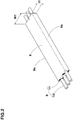
- Fig. 2 is a perspective view of a part of the rubber-coated cord strip 9.
- the rubber-coated cord strip 9 has two side edges 9s extending in the longitudinal direction thereof, and has a substantially rectangular cross sectional shape.
- the width w1 of the rubber-coated cord strip 9 is preferably set in a range from 2.5 to 12.0 mm, for example.
- the thickness t1 of the rubber-coated cord strip 9 is preferably set in a range from 0.6 to 3.0 mm, for example.
- the rubber-coated cord strip 9 is formed by covering one or more reinforcing cords 10 with an unvulcanized topping rubber 11.
- steel cords and/or organic fiber cords are preferably used as the reinforcing cords 10.
- the reinforcing cords 10 extend in parallel with the side edge 9s.
- Fig. 3 is a developed plan view of the tread reinforcing layer 7 which is developed in the tire circumferential direction and axial direction.
- the rubber-coated cord strip 9 is indicated by a single solid line (corresponding to the center line in the widthwise direction) for convenience sake.
- the length between the upper and lower ends in Fig. 3 of the tread reinforcing layer 7 corresponds to the entire circumferential length of the tread reinforcing layer 7.
- the tread reinforcing layer 7 comprises a pair of middle reinforcing parts 7M each formed by winding a rubber-coated cord strip 9 around one of the middle regions 2M, and a pair of shoulder reinforcing parts 7S each formed by winding a rubber-coated cord strip 9 around one of the shoulder regions 2S.
- the middle reinforcing parts 7M and shoulder reinforcing parts 7S are formed from separate rubber-coated cord strips 9. However, it is also possible to use one continuous rubber-coated cord strip 9 for forming one of the middle reinforcing parts 7M and one of the shoulder reinforcing parts 7S which are adjacent to each other.
- the tread reinforcing layer 7 in this embodiment comprises a crown reinforcing part 7C formed by winding a rubber-coated cord strip 9 around the crown region 2C.
- the crown reinforcing part 7C in this embodiment is formed from a rubber-coated cord strip 9 separate from those of the middle reinforcing parts 7M.
- Each of the middle reinforcing parts 7M of this embodiment comprises a plurality of inclining segments 13 in which the rubber-coated cord strip 9 is inclined.
- Each of the middle reinforcing parts 7M has the inner edge Ei on the tire equator C side and the outer edge Ee on the tread edge TE side.
- the plurality of inclining segments 13 of this embodiment includes a plurality of first inclining segments 15 inclined to one side (diagonally right up in the figure) with respect to the tire circumferential direction, and a plurality of second inclining segments 16 inclined to the other side (diagonally right down in the figure) opposite to the plurality of first inclining segments 15.
- Such inclining segments 13 increase the torsional rigidity of the middle regions 2M to cause a high cornering power, therefore, the turning or cornering performance is improved.
- the middle reinforcing parts 7M are each formed as a mesh structure having a plurality of rhombic spaces 17 surrounded by the first inclining segments 15 and second inclining segments 16.
- a tension acting on a part of the middle reinforcing part 7M can be dispersed over a wide range of the mesh structure through portions of the rubber-coated cord strip 9 intersecting with each other, so the rigidity of the middle region 2M is increased and the cornering performance is improved.
- the term "rhombic" shape refers to a shape surrounded by the first inclining segments 15 and second inclining segments 16 which segments extend straight, and it is not limited to a rhomboid in a strict sense, and it also includes a parallelogram and the like.
- the term “straight” is not limited to “straight” in a strict sense, and may be a slightly curved arc, for example, because the tread portion 2 is formed in an arc shape, but wavy and zigzag formed by repeating a unit are excluded.
- the first inclining segments 15 have an angle ⁇ 1 of more than 2 degrees, more preferably 3 to 10 degrees with respect to the tire circumferential direction
- the second inclining segments 16 have an angle ⁇ 2 of more than 2 degrees, more preferably 3 to 10 degrees with respect to the tire circumferential direction.
- the cornering power of the tire can be adjusted.
- the angle ⁇ 1 is the same as the angle ⁇ 2.
- Each of the shoulder reinforcing parts 7S in this embodiment includes a shoulder spiral part 20 composed of a rubber-coated cord strip 9 wound spirally and circumferentially of the tire more than one turn so that the rubber-coated cord strip extends substantially in parallel with the tire circumferential direction.
- Such shoulder spiral part 20 can suppress the increase in the torsional rigidity of the shoulder regions 2S to allow to generate a smaller cornering power.
- each of the shoulder reinforcing parts 7S is made up of the shoulder spiral part 20 only.
- the expansion "the rubber-coated cord strip extends substantially in parallel with the tire circumferential direction” means that the angle of the rubber-coated cord strip 9 is in a range from 0 to 8 degrees with respect to the tire circumferential direction.
- the values of the angle ⁇ 3 with respect to the tire circumferential direction in the shoulder spiral parts 20 refer to those obtained by averaging the angle over the circumference of the tire in order to exclude a portion inclined at a large angle.
- the axially outer edges of the shoulder reinforcing parts 7S correspond to the axially outer edges 7e of the tread reinforcing layer 7.
- the width ws of each of the shoulder spiral parts 20 measured along the tread surface 2a of the tread portion 2 is not less than 5 % of the width Wt of the tread reinforcing layer 7. Thereby, the sense of ground contacting during full-bank cornering can be certainly improved. If the width ws of the shoulder spiral part 20 is excessively increased, the cornering power during cornering not in the full-bank state becomes small, and there is a possibility that the cornering performance is rather deteriorated.
- the width ws of the shoulder spiral part 20 is set to be not more than 10 % of the width Wt of the tread reinforcing layer 7.
- the rubber-coated cord strip 9 forming the shoulder spiral part 20 has only one reinforcing cord 10 embedded therein. Thereby, it becomes easy to adjust the cornering power caused by the shoulder region 2S to desirable values in order to improve the cornering performance, by adjusting the winding pitches of the rubber-coated cord strip 9.
- the width W1 is, for example, 2.5 to 3.5 mm
- the thickness t1 is, for example, 0.6 to 3.0 mm.
- the crown reinforcing part 7C in this embodiment includes a crown spiral part 21 formed by winding the rubber-coated cord strip 9 spirally and circumferentially of the tire more than one turn.
- Such crown spiral part 21 can suppress the increase in the torsional rigidity of the crown region 2C to allow to generate smaller cornering power.
- the crown reinforcing part 7C is made up of the crown spiral part 21 only.
- the width wc of the crown spiral part 21 measured along the tread surface 2a of the tread portion 2 is set to be not less than 5 % of the width wt of the tread reinforcing layer 7. Thereby, the sense of ground contacting during straight running can be certainly improved. If the width wc of the crown spiral part 21 is excessively increased, the cornering power during cornering becomes decreased, and there is a possibility that the cornering performance is deteriorated.
- the width Wc of the crown spiral part 21 is not more than 15 % of the width Wt of the tread reinforcing layer 7.
- the rubber-coated cord strip 9 forming the crown spiral part 21 has only one reinforcing cord 10 embedded therein. Thereby, it becomes easy to adjust the cornering power caused by the crown region 2C to desirable values in order to improve the high-speed stability performance, by adjusting the winding pitches of the rubber-coated cord strip 9.
- the side edges 9s of the rubber-coated cord strip 9 which are adjacent to each other in the tire axial direction are in contact with each other in this embodiment, although they can be partially overlapped or separated in the tire axial direction.
- Each of the middle reinforcing parts 7M in this embodiment further comprises a plurality of circumferential segments 14 in which the rubber-coated cord strip 9 extends in the tire circumferential direction.
- both ends in the tire circumferential direction of each of the circumferential segments 14 are connected to two of the inclining segments 13.
- the plurality of circumferential segments 14 of this embodiment includes a plurality of inner circumferential segments 18 and a plurality of outer circumferential segments 19.
- the inner circumferential segments 18 are connected to axially inner ends 15i of the first inclining segments 15 and axially inner ends 16i of the second inclining segments 16.
- Such inner circumferential segments 18 can enhance the binding force to a portion close to the crown region 2C, and improves the high-speed stability performance.
- the inner circumferential segments 18 extending in the tire circumferential direction can reduce the change in the rigidity at the boundary between the crown reinforcing part 7C and the middle reinforcing part 7M and improve transient characteristics during cornering. Thereby, the cornering performance of the tire 1 is improved.
- the length in the tire circumferential direction La of each of the inner circumferential segments 18 is set in a range from 50 % to 150 % of the maximum length in the tire circumferential direction L1 of the spaces 17.
- the difference between the rigidity at the boundaries between the crown region 2C and the middle regions 2M, and the rigidity of the crown regions 2C and the rigidity of the middle regions 2M, is further decreased, the transient characteristics are further improved, and the inner circumferential segments 18 exert a large binding force.
- the cornering performance and the high-speed stabilizing performance can be further improved.
- the maximum length L1 of the spaces 17 closest to the inner circumferential segments 18 is adopted.
- the inner circumferential segments 18 are provided at the same axial positions as the intersecting positions K1, on the most tire equator C side, between the first inclining segments 15 and the second inclining segments 16.
- the length La in the tire circumferential direction of the inner circumferential segments 18 becomes equal to 100 % of the maximum length L1 in the tire circumferential direction of the spaces 17.
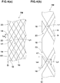
- Fig. 4(a) shows the middle reinforcing parts 7M in which the length La in the tire circumferential direction of the inner circumferential segments 18 is smaller than the maximum length L1 in the tire circumferential direction of the spaces 17.
- the inner circumferential segments 18 are arranged at the inner edge Ei with gaps 23 alternating in the tire circumferential direction.
- the inner circumferential segments 18 are arranged so as to be displaced in the tire axial direction from the intersecting positions K1, on the most tire equator side, between the first inclining segments 15 and the second inclining segments 16.
- Fig. 4(b) shows the middle reinforcing part 7M in which the length La in the tire circumferential direction of the inner circumferential segments 18 is larger than the maximum length L1 in the tire circumferential direction of the spaces 17.
- the inner circumferential segments 18 are arranged at the inner edge Ei with gaps 23 alternating in the tire circumferential direction.
- the outer circumferential segments 19 are connected to the outer ends 15e in the tire axial direction of the first inclining segments 15 and the other ends 16e in the tire axial direction of the second inclining segments 16.
- Such outer circumferential segments 19 can reduce bending stress acting on the reinforcing cords 10 of the rubber-coated cord strip 9, for example, as compared with the case where the first inclining segment 15 and the second inclining segment 16 are directly connected to each other.
- the outer circumferential segments 19 can reduce the change in the rigidity between the shoulder regions 2S and the middle regions 2M, and improve the transient characteristics during cornering with relatively large bank angles. Thereby, the cornering performance of the tire 1 can be improved.
- the plurality of outer circumferential segments 19 is configured in the same manner as the plurality of inner circumferential segments 18.
- outer circumferential segments 19 are provided at the same axial positions as the intersecting positions K2, on the most tread edge TE side, between the first inclining segments 15 and the second inclining segments 16.
- angle ⁇ 5 of the inner circumferential segments 18 with respect to the tire circumferential direction, and the angle ⁇ 6 of the outer circumferential segments 19 with respect to the tire circumferential direction are smaller than the angle ⁇ 1 of the first inclining segments 15, and smaller than the angle ⁇ 2 of the second inclining segments 16.
- the angle ⁇ 5 of the inner circumferential segments 18 and the angle ⁇ 6 of the outer circumferential segments 19 are preferably set to be not more than 5 degrees, more preferably not more than 3 degrees, still more preferably not more than 1 degree.
- Fig. 5 is an enlarged view showing the vicinity of the boundary between the middle reinforcing part 7M and the shoulder reinforcing part 7S.
- an axial distance Wa is smaller than 500 % of an axial distance wb, wherein the axial distance Wa is a distance between the axially outermost reinforcing cord 10a in the outer circumferential segment 19, and the reinforcing cord 10b in the shoulder reinforcing part 7S which cord is adjacent in the tire axial direction to the above-said axially outermost reinforcing cord 10a, and the axial distance wb is a distance between the reinforcing cords 10 in the shoulder reinforcing part 7S which cords are adjacent to each other in the tire axial direction.
- the axial distance Wa is more than 500 % of the axial distance wb, then a change in the difference between the rigidity of the portion where the outer circumferential segments 19 are disposed and the rigidity of the shoulder reinforcing part 7S is increased, and there is a possibility that the transient characteristics are deteriorated when making turn with relatively large bank angles.
- the axial distance wa is not less than 50 % of the axial distance wb.
- Fig. 6 is an enlarged view showing the vicinity of the boundary between the middle reinforcing part 7M and the crown reinforcing part 7C.
- the axial distance wf is less than 500 % of the axial distance wh, wherein the axial distance wf is a distance between the axially innermost reinforcing cord 10f in the inner circumferential segment 18, and the reinforcing cord 10h in the crown reinforcing part 7C which cord is adjacent in the tire axial direction to the axially innermost reinforcing cord 10f, and the axial distance wh is a distance between the reinforcing cords 10 in the crown reinforcing part 7C which cords are adjacent to each other in the tire axial direction.
- the axial distance wf is more than 500 % of the axial distance wh, then a change in the difference between the rigidity of the portion where the inner circumferential segments 18 are disposed and the rigidity of the crown reinforcing part 7C is increased, and there is a possibility that the transient characteristics are deteriorated when making turn with relatively small bank angles.
- the axial distance wf is not less than 50 % of the axial distance Wh.
- the tire 1 in this embodiment is manufactured through a step of forming a green tire and a step of vulcanization molding the green tire.
- the step of forming the green tire includes a tread reinforcing layer forming step for forming the tread reinforcing layer 7 described above.
- the tread reinforcing layer forming step includes a winding step of winding the long rubber-coated cord strip 9. Except for the winding step in the tread reinforcing layer forming step, descriptions of the step of forming the green tire and the step of vulcanization molding the green tire are omitted since known steps can be adopted therefor.
- the winding step in this embodiment includes a crown winding step, a first middle winding step, a second middle winding step, a first shoulder winding step and a second shoulder winding step.
- a crown reinforcing part 7C is formed.
- one of the middle reinforcing parts 7M is formed.
- the other of the middle reinforcing parts 7M is formed.
- one of the shoulder reinforcing parts 7S is formed.
- each of the reinforcing parts 7C, 7M and 7S is formed from one rubber-coated cord strip 9.
- the first shoulder winding step, the first middle winding step, the crown winding step, the second middle winding step, and the second shoulder winding step are carried out in this order.
- the winding step is however, not limited to such mode. For example, it may be started from the crown winding step or the first middle winding step.
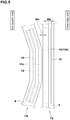
- Fig. 7 is a diagram for explaining the winding step. As shown in Fig. 7 , in the winding step, the rubber-coated cord strip 9 is wound on the outer circumferential surface 31a of a profiled drum 31, directly or indirectly through the carcass 6.
- the profile drum 31 in this embodiment is of a well-known structure having an outer circumferential surface 31a provided with a profile curved convexly toward the radially outside.
- the profile drum 31 is composed of a plurality of segments, for example, and the outer circumferential surface 31a is configured to be expandable/contractible by radially moving an expansion device 35 disposed inside the profile drum 31.
- the carcass holding device 36 is a ring-shaped member movable in the axial direction, and attached to the support shaft 37, and can rotate concentrically and integrally with the profile drum 31.
- the carcass holding devices 36 can hold the cylindrical carcass 6 together with the bead cores 5.
- the rubber-coated cord strip 9 is continuously supplied to the profile drum 31 by, for example, a known applicator 34.
- the applicator 34 is reciprocated in an arced locus along the outer circumferential surface 31a of the profile drum 31 by, for example, a well-known three-dimensional moving device (not shown) or the like. As a result, the rubber-coated cord strip 9 is wound on the outer circumferential surface 31a.
- the rubber-coated cord strip 9 wound in the first shoulder winding step has only one reinforcing cord 10 embedded therein.
- the rubber-coated cord strip 9 is spirally wound more than one turn from one of the axial edges to the other of the shoulder reinforcing parts 7S.
- the rubber-coated cord strip 9 is spirally wound from the other axial edge to the one axial edge of the shoulder reinforcing part 7S.
- the winding start end and the winding stop end of the rubber-coated cord strip 9 are placed at substantially same circumferential points at different axial positions.
- Fig. 8(a) is a plan view showing a state of one of the middle reinforcing part 7M immediately after the winding of the rubber-coated cord strip 9 is started, wherein turns of the rubber-coated cord strip 9 not yet wound are indicated by imaginary lines, and a turn of the rubber-coated cord strip 9 partially wound is indicated by solid lines and reference numeral 9f.
- Fig. 8(b) is a plan view showing a state of the middle reinforcing part 7M when the winding of the rubber-coated cord strip 9 has been progressed more than Fig. 8(a) , wherein a turn of the rubber-coated cord strip 9 partially wound is indicated by reference numeral 9h.
- the winding start end 9d at the beginning of winding of the rubber-coated cord strip 9 is firstly fixed to, for example, the inner edge Ei of the middle reinforcing part 7M.
- the winding start end 9d may be fixed to the outer edge Ee or a position on one of the inclining portions 13 of the middle reinforcing part 7M.
- the rubber-coated cord strip 9 wound in the first middle winding step has a plurality of the reinforcing cords 10, for example, three reinforcing cords 10 embedded therein.
- the applicator 34 supplies the rubber-coated cord strip 9 to the outer circumferential surface 31a of the rotating profiled drum 31 while reciprocating between the inner edge Ei and the outer edge Ee.
- the rubber-coated cord strip 9 is wound zigzag, comprising the first inclining segments 15 and the second inclining segments 16, so that the side edges 9s (shown in Fig. 2 ) of the rubber-coated cord strip 9 do not contact with each other.
- the rubber-coated cord strip 9 is wound in the order of the first inclining segment 15, the outer circumferential segment 19, the second inclining segment 16, the inner circumferential segment 18 and the first inclining segment 15 ---.
- both ends of each of the inner circumferential segments 18 are connected to one of the first inclining segments 15 and one of the second inclining segments 16, and both ends of each of the outer circumferential segments 19 are connected to one of the first inclining segments 15 and one of the second inclining segments 16.
- the rubber-coated cord strip 9 can be formed into a mesh having rhombic spaces 17 surrounded by the first inclining segments 15 and the second inclining segments 16.
- each inner circumferential segment 18 substantially coincides in the tire circumferential direction with the other end of one of the inner circumferential segments 18 which is adjacent in the tire circumferential direction to the above-said one end.
- Such arrangement further enhances the binding force at the boundary portion between the crown reinforcing part 7C and the middle reinforcing parts 7M, and further enhances the high-speed stability performance.
- each outer circumferential segment 19 substantially coincides in the tire circumferential direction with the other end of one of the outer circumferential segments 19 which is adjacent in the tire circumferential direction to the above-said one end. Thereby, the cornering performance is further improved.
- the first middle winding step is however, not limited to such arrangement.
- one end of each inner circumferential segment 18 is separated in the tire circumferential direction from the other end of one of the inner circumferential segments 18 which is adjacent in the tire circumferential direction to the above-said one end.
- one end of each inner circumferential segment 18 is overlapped in the tire circumferential direction with the other end of one of the inner circumferential segments 18 which is adjacent in the tire circumferential direction to the above-said one end.
- the winding stop end 9e of the rubber-coated cord strip 9 when ending the winding is fixed so as to continue to the winding start end 9d in the tire circumferential direction.
- the inner circumferential segments 18 are arranged in line, and form corners with the first inclining segments 15 and the second inclining segments 16, and the outer circumferential segments 19 are arranged in line, and form corners with the first inclining segments 15 and the second inclining segments 16.
- the crown winding step is performed.
- one rubber-coated cord strip 9 different from that in the first middle winding step is used.
- a single reinforcing cord 10 is embedded along the longitudinal direction.
- the rubber-coated cord strip 9 is spirally wound from one of the axial edges toward the other of the axial edges of the crown reinforcing part 7C more than one turn.
- the winding start end and the winding stop end of the rubber-coated cord strip 9 are fixed to substantially same circumferential points at different axial positions.
- the second middle winding step and the second shoulder winding step are performed.
- the second middle winding step is performed by using one rubber-coated cord strip 9 different from that in the crown winding step.
- the second shoulder winding step is performed by using one rubber-coated cord strip 9 different from that in the second middle winding step.
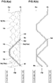
- Figs. 9(a) and 9(b) schematically show a first middle winding step or a second middle winding step of another embodiment.
- Fig. 9(a) is a plan view showing a state of the middle reinforcing part 7M immediately after the winding of the rubber-coated cord strip 9 is started, wherein turns of the rubber-coated cord strip 9 not yet wound are indicated by imaginary lines, and a turn of the rubber-coated cord strip 9 partially wound is indicated by solid lines and reference numeral 9f.
- Fig. 9(b) is a plan view showing a state of the middle reinforcing part 7M when the winding of the rubber-coated cord strip 9 has been progressed more than Fig. 9(a) , wherein one turn of the rubber-coated cord strip 9 and a turn partially wound are indicated by reference numeral 9h, and the rubber-coated cord strip 9 is wound in the order indicated by allowed imaginary lines a, b, c and d.
- the winding start end 9d at the beginning of winding of the rubber-coated cord strip 9 is fixed to the outer edge Ee of the middle reinforcing part 7M.
- the winding start end 9d may be fixed to the inner edge Ei or a position on one of the inclining portions 13 of the middle reinforcing parts 7M.
- the applicator 34 supplies the rubber-coated cord strip 9 to the outer circumferential surface 31a of the rotating profiled drum 31 while reciprocating between the inner edge Ei and the outer edge Ee.
- the rubber-coated cord strip 9 is wound in the order of a first inclining segment 15, an inner circumferential segment 18, a first inclining segment 15, an outer circumferential segment 19, a first inclining segment 15 ---.
- the rubber-coated cord strip 9 is wound in the order of a second inclining segment 16, an inner circumferential segment 18, a second inclining segment 16, an outer circumferential segment 19, a second inclining segment 16 ---.
- the middle reinforcing part 7M is formed such that both ends of each inner circumferential segment 18 are connected to two of the first inclining segments 15 adjacent to each other in the tire circumferential direction, or alternatively two of the second inclining segments 16 adjacent to each other in the tire circumferential direction.
- the middle reinforcing part 7M is provided with a mesh structure having a plurality of rhombic spaces 17 surrounded by the first inclining segments 15 and the second inclining segments 16.
- Fig. 10(a) is a plan view showing another example of the connection of the first inclining segment 15, the second inclining segment 16 and the inner circumferential segment 18.
- the inner circumferential segment 18 includes an arcuate portion 18y.
- the inner circumferential segments 18 is formed by the arcuate portion 18y only.
- the arcuate portion 18y is smoothly connected to the first inclining segment 15 and the second inclining segment 16.
- the angle ⁇ 5 of the inner circumferential segment 18 is set in a range of not more than 5 degrees with respect to the tire circumferential direction.
- the outer circumferential segment 19 may be formed by an arcuate portion so as to be smoothly continuous with the first inclining segment 15 and the second inclining segment 16 in the same manner as shown in Fig. 10(a) .
- the bending stress acting on the reinforcing cords 10 of the rubber-coated cord strip 9 is reduced, and the cornering performance is improved.
- Fig. 10(b) is a plan view showing another example of the connection of the inner circumferential segment 18 and the inclining segments 13 (in the figure, first inclining segments 15).
- the first inclining segment 15 comprises a main portion 15x extending substantially straight at the above-mentioned angle ⁇ 1 of more than 5 degrees with respect to the tire circumferential direction, and an arcuate portion 15y smoothly continued from the main portion 15x and extending in an arc shape.
- the inner circumferential segment 18 comprises a main portion 18x extending substantially straight at the above-mentioned angle ⁇ 5 smaller than that of the first inclining segments 15, and an arcuate portion 18y smoothly continued from the main portion 18x and extending in an arc shape.
- the main portion 15x of the first inclining segment 15 and the main portion 18x of the inner circumferential segment 18 are smoothly connected via the arcuate portion 15y and the arcuate portion 18y.
- connection mode can be applied to the connection between the second inclining segment 16 and the inner circumferential segments 18, the connection between the outer circumferential segment 19 and the first inclining segment 15, and/or the connection between the outer circumferential segment 19 and the second inclining segment 16.
- each middle reinforcing part 7M is extended to the axially outer edge 7e of the tread reinforcing layer.
- Rubber-coated cord strip for the middle reinforcing parts 4.0 mm in width, 1.0 mm in thickness, three reinforcing cords embedded
- Rubber-coated cord strip for the crown reinforcing part and the shoulder reinforcing parts 2.5 mm in width, 1.0 mm in thickness, one reinforcing cord embedded
- width wt of the tread reinforcing layer 90 % of TW
- test tires were mounted on all wheels of a 130cc motorcycle under the following conditions.
- Front wheel tire size 120/70ZR17, rim size 17M/CxMT3.50, tire pressure 250 kPa
- Rear wheel tire size 190/55ZR17, rim size 17M/CxMT5.50, tire pressure 250 kPa
- the motorcycle was run on a dry asphalt road in a test course, and the test tire was evaluated by the test rider based on high-speed running characteristics relating to handling stability, grip and the like, and cornering performance relating to transient characteristics during cornering, operability of the handle and the like.
- the cornering power obtained herein is the cornering force per 1 degree of the slip angle.
- Table 1 The results are indicated in Table 1 by an index based on Comparative Example 1 being 100, wherein the larger the value, the higher the cornering power.
Abstract
Description
- The present invention relates to a motorcycle tire, more particularly to a tread reinforcing layer capable of improving cornering performance.
- Patent Document 1 below discloses a motorcycle tire provided in the tread portion with a band composed a center portion having a spiral cord structure, and shoulder portions on both sides thereof having a mesh-like cord structure. As a result, relatively, the torsional rigidity of the shoulder portions is enhanced, and the turning or cornering performance is improved.
- Patent document 1: Japanese Patent Application Publication No.
2017-177842 - In recent years, on the other hand, along with the improvement in performance of motorcycles, motorcycle tires are required to be further improved in cornering performance.
- Therefore, the present invention was made in view of the above circumstances, and a primary object of the present invention is to provide a motorcycle tire improved in the turning or cornering performance.
- According to the present invention, a motorcycle tire comprises:
- a toroidal carcass, and
- a tread reinforcing layer disposed radially outside the carcass in a tread portion,
- the tread reinforcing layer comprising
a pair of shoulder reinforcing parts each formed by winding a rubber-coated cord strip of at least one rubberized reinforcing cord covered with topping rubber, around one of shoulder regions, and
a pair of middle reinforcing parts each formed by winding a rubber-coated cord strip, around one of middle regions axially inside the shoulder regions,
wherein - each of the middle reinforcing parts comprises
a plurality of first inclining segments in which the rubber-coated cord strip is inclined to one side with respect to the tire circumferential direction, and
a plurality of second inclining segments in which the rubber-coated cord strip is inclined to the other side opposite to the plurality of first inclining segments, with respect to the tire circumferential direction, wherein
side edges of the first inclining segments are arranged so as not to contact with each other, and side edges of the second inclining segments are arranged so as not to contact with each other, whereby a mesh structure having a plurality of rhombic spaces surrounded by the first inclining segments and the second inclining segments is formed, and - each of the shoulder reinforcing parts includes a shoulder spiral part in which the rubber-coated cord strip is wound spirally and circumferentially of the tire more than one turns.
- In the motorcycle tire according to the present invention, it is preferable that each of the middle reinforcing parts comprises a plurality of inner circumferential segments in which the rubber-coated cord strip extends in the tire circumferential direction continuously from axially inner ends of the first inclining segments and second inclining segments, and
the length in the tire circumferential direction of the inner circumferential segments is in a range from 50 % to 150 % of the maximum length in the tire circumferential direction of the spaces. - In the motorcycle tire according to the present invention, it is preferable that the width measured along the tread surface of the tread portion, of the shoulder spiral part, is not less than 5 % of the width measured along the tread surface of the tread portion, of the tread reinforcing layer.
- In the motorcycle tire according to the present invention, it is preferable that the tread portion has a crown region between the middle regions, and
the tread reinforcing layer comprises a crown reinforcing part including a crown spiral part in which the rubber-coated cord strip is wound spirally and circumferentially of the tire, around the crown region more than one turn. - In the motorcycle tire according to the present invention, it is preferable that the width measured along the tread surface of the tread portion, of the crown spiral part is not less than 5 % of the width measured along the tread surface of the tread portion, of the tread reinforcing layer.
- In the motorcycle tire according to the present invention, it is preferable that the rubber-coated cord strip forming the crown spiral part has only one reinforcing cord embedded therein.
- In the motorcycle tire according to the present invention, it is preferable that the rubber-coated cord strip forming the shoulder spiral part has only one reinforcing cord embedded therein.
- In the motorcycle tire according to the present invention, it is preferable that each of the middle reinforcing parts comprises a plurality of inner circumferential segments in which the rubber-coated cord strip extends in the tire circumferential direction continuously from the axially inner ends of the first inclining segments and second inclining segments, and
both ends of each of the inner circumferential segments are connected to two of the circumferentially adjacent first inclining segments or alternatively two of the circumferentially adjacent second inclining segments. - In the motorcycle tire according to the present invention, it is preferable that each of the middle reinforcing parts comprises a plurality of circumferential segments in which the rubber-coated cord strip extends in the tire circumferential direction continuously from the axially inner ends of the first inclining segments and second inclining segments, and
both ends of each of circumferential segments are connected to one of first inclining segments and one of the second inclining segments. - The motorcycle tire according to the present invention comprises the middle reinforcing part formed from the rubber-coated cord strip wound around the middle region mainly contacting with the ground during cornering, and the shoulder reinforcing part formed from the rubber-coated cord strip wound around the shoulder region mainly contacting with the ground during full-bank cornering. The middle reinforcing part comprises the first inclining segments and the second inclining segments in which the rubber-coated cord strip is inclined to the opposite directions with respect to the tire axial direction. Such middle reinforcing part increases the torsional rigidity of the middle region to allow to generate larger cornering power.
- The middle reinforcing parts is provided with the mesh structure having the plurality of rhombic spaces surrounded by the first inclining segments and the second inclining segments. Such middle reinforcing part increases the rigidity of the middle region because a tension acting on a part of the middle reinforcing part can be dispersed over a wide range of the mesh structure through portions of the rubber-coated cord strip intersecting with each other. Therefore, the middle reinforcing part helps to exert excellent cornering performance.
- The shoulder reinforcing part includes the shoulder spiral part formed form the rubber-coated cord strip wound spirally and circumferentially of the tire more than one turn. Such shoulder reinforcing part suppresses an increase in the torsional rigidity of the shoulder region to allow to generate relatively small cornering power. Therefore, it is possible to reduce reaction forces and vibrations caused by, for example, gaps of a road surface, and the sense of ground contacting is improved. As a result, full-bank cornering becomes stable, and the cornering performance can be further improved.
- Therefore, the motorcycle tire according to the present invention can exhibit excellent cornering performance.
-
-
Fig. 1 is a cross sectional view of a motorcycle tire as an embodiment of the present invention. -
Fig. 2 is a schematic perspective view of a rubber-coated cord strip. -
Fig. 3 is a schematic developed plan view of the tread reinforcing layer. -
Fig. 4(a) and Fig. 4(b) are diagrams showing another example of the shoulder reinforcing part. -
Fig. 5 is an enlarged partial view showing the middle reinforcing part and the shoulder reinforcing part shown inFig. 3 . -
Fig. 6 is an enlarged partial view showing the middle reinforcing part and the crown reinforcing part shown inFig. 3 . -
Fig. 7 is a diagram for explaining a process of winding the rubber-coated cord strip. -
Fig. 8(a) and Fig. 8(b) are diagrams for explaining a process of forming the middle reinforcing part of this embodiment. -
Fig. 9(a) andFig. 8(b) are diagrams for explaining a process of forming another example of the middle reinforcing part of this embodiment. -
Fig. 10(a) and Fig. 10(b) show connection modes between the inclining portion and the circumferentially extending portion of the middle reinforcing part. - Embodiments of the present invention will now be described in detail with reference to the accompanying drawings.
-
Fig. 1 is a meridian cross sectional view of a motorcycle tire as an embodiment of present invention under its normal state. - The "normal state" is a state in which the tire 1 is mounted on a standard rim (not shown), inflated to a standard pressure, and loaded with no tire load.
- In the present specification, unless otherwise noted, dimensions of each part of the tire 1 refer to values measured under the normal state.
- The "standard rim" is a rim specified for the tire in a standard system comprising the standard on which the tire 1 is based, for example, "Standard rim" for JATMA, "Design rim" for TRA, "Measuring rim" for ETRTO.
- The "standard pressure" is an air pressure specified for the tire in a standard system comprising the standard on which the tire 1 is based, for example, "Maximum air pressure" for JATMA, "Inflation pressure" for ETRTO, Maximum value specified in "TIRE LOAD LIMITS AT VARIOUS COLD INFLATION PRESSURES" table for TRA.
- As shown in
Fig. 1 , the tire 1 in this embodiment comprises atread portion 2 having atread surface 2a coming into contact with the ground, atoroidal carcass 6, and atread reinforcing layer 7 disposed radially outside thecarcass 6 in thetread portion 2. - The
tread portion 2 is curved in an arc shape being convex toward the radially outside, and has a pair of tread edges TE. The tread edges TE are positioned on the most outsides in the tire axial direction. - The
tread portion 2 has a pair ofshoulder regions 2S, and a pair ofmiddle regions 2M axially inside therespective shoulder regions 2S. Theshoulder regions 2S are regions extending from the tread edges TE to the axially outer edges of themiddle regions 2M. Theshoulder regions 2S are region contacting with the ground mainly during full-bank cornering. Themiddle regions 2M are regions contacting with the ground mainly during cornering. - The
tread portion 2 further comprises acrown region 2C between themiddle regions 2M. Thecrown region 2C is a region including the tire equator C and contacting with the ground mainly during straight running at high speed. - The
carcass 6 is composed of at least onecarcass ply 6A. For example, thecarcass ply 6A is made of carcass cords rubberized with an unvulcanized topping rubber, and arranged at an angle of 75 to 90 degrees with respect to the tire equator C. For example, thecarcass ply 6A comprises amain portion 6a extending from thetread portion 2 to beadcores 5 on both sides disposed in therespective bead portions 4 through therespective sidewall portions 3, and a pair ofturnup portions 6b extending continuously from themain portion 6a. - In the meridian cross section of the tire, the
tread reinforcing layer 7 extends curvedly along thetread portion 2 and is formed over the substantially entire width of thetread portion 2. As a result, thetread reinforcing layer 7 can increase the rigidity of thetread portion 2 over the entire width of thetread portion 2. - From this point of view, it is preferable that the width wt of the
tread reinforcing layer 7 measured along thetread surface 2a of thetread portion 2 is set in a range from 75 % to 95 % of the width TW between the tread edges TE measured along thetread surface 2a of thetread portion 2, namely, the developed tread width TW. - The
tread reinforcing layer 7 of this embodiment is formed by winding a rubber-coatedcord strip 9 around thecarcass 6. -
Fig. 2 is a perspective view of a part of the rubber-coatedcord strip 9. As shown inFig. 2 , the rubber-coatedcord strip 9 has twoside edges 9s extending in the longitudinal direction thereof, and has a substantially rectangular cross sectional shape. The width w1 of the rubber-coatedcord strip 9 is preferably set in a range from 2.5 to 12.0 mm, for example. The thickness t1 of the rubber-coatedcord strip 9 is preferably set in a range from 0.6 to 3.0 mm, for example. - For example, the rubber-coated
cord strip 9 is formed by covering one or more reinforcingcords 10 with anunvulcanized topping rubber 11. For example, steel cords and/or organic fiber cords are preferably used as the reinforcingcords 10. In this embodiment, the reinforcingcords 10 extend in parallel with theside edge 9s. -
Fig. 3 is a developed plan view of thetread reinforcing layer 7 which is developed in the tire circumferential direction and axial direction. InFig. 3 , the rubber-coatedcord strip 9 is indicated by a single solid line (corresponding to the center line in the widthwise direction) for convenience sake. The length between the upper and lower ends inFig. 3 of thetread reinforcing layer 7 corresponds to the entire circumferential length of thetread reinforcing layer 7. - As shown in
Fig. 3 , thetread reinforcing layer 7 comprises a pair ofmiddle reinforcing parts 7M each formed by winding a rubber-coatedcord strip 9 around one of themiddle regions 2M, and a pair ofshoulder reinforcing parts 7S each formed by winding a rubber-coatedcord strip 9 around one of theshoulder regions 2S. - The
middle reinforcing parts 7M andshoulder reinforcing parts 7S are formed from separate rubber-coated cord strips 9. However, it is also possible to use one continuous rubber-coatedcord strip 9 for forming one of themiddle reinforcing parts 7M and one of theshoulder reinforcing parts 7S which are adjacent to each other. - Further, the
tread reinforcing layer 7 in this embodiment comprises acrown reinforcing part 7C formed by winding a rubber-coatedcord strip 9 around thecrown region 2C. Thecrown reinforcing part 7C in this embodiment is formed from a rubber-coatedcord strip 9 separate from those of themiddle reinforcing parts 7M. However, it is also possible to use one continuous rubber-coated cord strip for forming thecrown reinforcing part 7C and themiddle reinforcing parts 7M. - Each of the
middle reinforcing parts 7M of this embodiment comprises a plurality of incliningsegments 13 in which the rubber-coatedcord strip 9 is inclined. Each of themiddle reinforcing parts 7M has the inner edge Ei on the tire equator C side and the outer edge Ee on the tread edge TE side. - The plurality of inclining
segments 13 of this embodiment includes a plurality offirst inclining segments 15 inclined to one side (diagonally right up in the figure) with respect to the tire circumferential direction, and a plurality ofsecond inclining segments 16 inclined to the other side (diagonally right down in the figure) opposite to the plurality offirst inclining segments 15. -
Such inclining segments 13 increase the torsional rigidity of themiddle regions 2M to cause a high cornering power, therefore, the turning or cornering performance is improved. - In each of the
middle reinforcing parts 7M, the side edges 15s of thefirst inclining segments 15 are arranged so as not to contact with each other, and the side edges 16s of thesecond inclining segments 16 are arranged so as not to contact with each other. Thereby, themiddle reinforcing parts 7M are each formed as a mesh structure having a plurality ofrhombic spaces 17 surrounded by thefirst inclining segments 15 andsecond inclining segments 16. As a result, a tension acting on a part of themiddle reinforcing part 7M can be dispersed over a wide range of the mesh structure through portions of the rubber-coatedcord strip 9 intersecting with each other, so the rigidity of themiddle region 2M is increased and the cornering performance is improved. - In the present specification, the term "rhombic" shape refers to a shape surrounded by the
first inclining segments 15 andsecond inclining segments 16 which segments extend straight, and it is not limited to a rhomboid in a strict sense, and it also includes a parallelogram and the like. - Further, the term "straight" is not limited to "straight" in a strict sense, and may be a slightly curved arc, for example, because the
tread portion 2 is formed in an arc shape, but wavy and zigzag formed by repeating a unit are excluded. - In the
middle reinforcing parts 7M, it is preferable that thefirst inclining segments 15 have an angle θ1 of more than 2 degrees, more preferably 3 to 10 degrees with respect to the tire circumferential direction, and
thesecond inclining segments 16 have an angle θ2 of more than 2 degrees, more preferably 3 to 10 degrees with respect to the tire circumferential direction. - By changing the angle θ1 and angle θ2, the cornering power of the tire can be adjusted.
- It is preferable that the angle θ1 is the same as the angle θ2.
- Each of the
shoulder reinforcing parts 7S in this embodiment includes ashoulder spiral part 20 composed of a rubber-coatedcord strip 9 wound spirally and circumferentially of the tire more than one turn so that the rubber-coated cord strip extends substantially in parallel with the tire circumferential direction. - Such shoulder spiral
part 20 can suppress the increase in the torsional rigidity of theshoulder regions 2S to allow to generate a smaller cornering power. - Therefore, it is possible to reduce reaction forces and vibrations caused by, for example, gaps of a road surface, to increase the ground contact. As a result, the
shoulder reinforcing part 7S can improve high-speed stability performance. In this embodiment, each of theshoulder reinforcing parts 7S is made up of theshoulder spiral part 20 only. - In this specification, the expansion "the rubber-coated cord strip extends substantially in parallel with the tire circumferential direction" means that the angle of the rubber-coated
cord strip 9 is in a range from 0 to 8 degrees with respect to the tire circumferential direction. - In this specification, the values of the angle θ3 with respect to the tire circumferential direction in the
shoulder spiral parts 20 refer to those obtained by averaging the angle over the circumference of the tire in order to exclude a portion inclined at a large angle. - The axially outer edges of the
shoulder reinforcing parts 7S correspond to the axiallyouter edges 7e of thetread reinforcing layer 7. - It is preferable that the width ws of each of the
shoulder spiral parts 20 measured along thetread surface 2a of thetread portion 2 is not less than 5 % of the width Wt of thetread reinforcing layer 7. Thereby, the sense of ground contacting during full-bank cornering can be certainly improved. If the width ws of theshoulder spiral part 20 is excessively increased, the cornering power during cornering not in the full-bank state becomes small, and there is a possibility that the cornering performance is rather deteriorated. - For this reason, it is preferable that the width ws of the
shoulder spiral part 20 is set to be not more than 10 % of the width Wt of thetread reinforcing layer 7. - It is preferable that the rubber-coated
cord strip 9 forming theshoulder spiral part 20 has only one reinforcingcord 10 embedded therein. Thereby, it becomes easy to adjust the cornering power caused by theshoulder region 2S to desirable values in order to improve the cornering performance, by adjusting the winding pitches of the rubber-coatedcord strip 9. - In the case of such rubber-coated
cord strip 9 in which only one reinforcingcord 10 is embedded, it is preferable that the width W1 is, for example, 2.5 to 3.5 mm, and the thickness t1 is, for example, 0.6 to 3.0 mm. - The
crown reinforcing part 7C in this embodiment includes acrown spiral part 21 formed by winding the rubber-coatedcord strip 9 spirally and circumferentially of the tire more than one turn. Such crown spiralpart 21 can suppress the increase in the torsional rigidity of thecrown region 2C to allow to generate smaller cornering power. - Therefore, reaction forces and vibrations caused by, for example, gaps of a road surface are reduced to increase the ground contact. As a result, high-speed stability performance can be improved.
- In this embodiment, the
crown reinforcing part 7C is made up of thecrown spiral part 21 only. - It is preferable that the width wc of the
crown spiral part 21 measured along thetread surface 2a of thetread portion 2 is set to be not less than 5 % of the width wt of thetread reinforcing layer 7. Thereby, the sense of ground contacting during straight running can be certainly improved. If the width wc of thecrown spiral part 21 is excessively increased, the cornering power during cornering becomes decreased, and there is a possibility that the cornering performance is deteriorated. - For this reason, it is preferable that the width Wc of the
crown spiral part 21 is not more than 15 % of the width Wt of thetread reinforcing layer 7. - It is preferable that the rubber-coated
cord strip 9 forming thecrown spiral part 21 has only one reinforcingcord 10 embedded therein. Thereby, it becomes easy to adjust the cornering power caused by thecrown region 2C to desirable values in order to improve the high-speed stability performance, by adjusting the winding pitches of the rubber-coatedcord strip 9. - In the
crown spiral part 21 and theshoulder spiral parts 20, the side edges 9s of the rubber-coatedcord strip 9 which are adjacent to each other in the tire axial direction are in contact with each other in this embodiment, although they can be partially overlapped or separated in the tire axial direction. - Each of the
middle reinforcing parts 7M in this embodiment further comprises a plurality ofcircumferential segments 14 in which the rubber-coatedcord strip 9 extends in the tire circumferential direction. - In this embodiment, both ends in the tire circumferential direction of each of the
circumferential segments 14 are connected to two of the incliningsegments 13. - The plurality of
circumferential segments 14 of this embodiment includes a plurality of innercircumferential segments 18 and a plurality of outercircumferential segments 19. - In this embodiment, the inner
circumferential segments 18 are connected to axiallyinner ends 15i of thefirst inclining segments 15 and axially inner ends 16i of thesecond inclining segments 16. Such innercircumferential segments 18 can enhance the binding force to a portion close to thecrown region 2C, and improves the high-speed stability performance. In addition, the innercircumferential segments 18 extending in the tire circumferential direction can reduce the change in the rigidity at the boundary between thecrown reinforcing part 7C and themiddle reinforcing part 7M and improve transient characteristics during cornering. Thereby, the cornering performance of the tire 1 is improved. - It is preferable that the length in the tire circumferential direction La of each of the inner
circumferential segments 18 is set in a range from 50 % to 150 % of the maximum length in the tire circumferential direction L1 of thespaces 17. Thereby, the difference between the rigidity at the boundaries between thecrown region 2C and themiddle regions 2M, and the rigidity of thecrown regions 2C and the rigidity of themiddle regions 2M, is further decreased, the transient characteristics are further improved, and the innercircumferential segments 18 exert a large binding force. As a result, the cornering performance and the high-speed stabilizing performance can be further improved. In this embodiment, the maximum length L1 of thespaces 17 closest to the innercircumferential segments 18 is adopted. - In this embodiment, the inner
circumferential segments 18 are provided at the same axial positions as the intersecting positions K1, on the most tire equator C side, between thefirst inclining segments 15 and thesecond inclining segments 16. As a result, the length La in the tire circumferential direction of the innercircumferential segments 18 becomes equal to 100 % of the maximum length L1 in the tire circumferential direction of thespaces 17. -
Fig. 4(a) shows themiddle reinforcing parts 7M in which the length La in the tire circumferential direction of the innercircumferential segments 18 is smaller than the maximum length L1 in the tire circumferential direction of thespaces 17. - In this
middle reinforcing part 7M, the innercircumferential segments 18 are arranged at the inner edge Ei withgaps 23 alternating in the tire circumferential direction. The innercircumferential segments 18 are arranged so as to be displaced in the tire axial direction from the intersecting positions K1, on the most tire equator side, between thefirst inclining segments 15 and thesecond inclining segments 16. -
Fig. 4(b) shows themiddle reinforcing part 7M in which the length La in the tire circumferential direction of the innercircumferential segments 18 is larger than the maximum length L1 in the tire circumferential direction of thespaces 17. In thismiddle reinforcing part 7M, too, the innercircumferential segments 18 are arranged at the inner edge Ei withgaps 23 alternating in the tire circumferential direction. - In this embodiment, as shown in
Fig. 3 , the outercircumferential segments 19 are connected to the outer ends 15e in the tire axial direction of thefirst inclining segments 15 and the other ends 16e in the tire axial direction of thesecond inclining segments 16. - Such outer
circumferential segments 19 can reduce bending stress acting on the reinforcingcords 10 of the rubber-coatedcord strip 9, for example, as compared with the case where thefirst inclining segment 15 and thesecond inclining segment 16 are directly connected to each other. - Further, at the boundaries between of the
shoulder reinforcing parts 7S and themiddle reinforcing parts 7M, the outercircumferential segments 19 can reduce the change in the rigidity between theshoulder regions 2S and themiddle regions 2M, and improve the transient characteristics during cornering with relatively large bank angles. Thereby, the cornering performance of the tire 1 can be improved. - The plurality of outer
circumferential segments 19 is configured in the same manner as the plurality of innercircumferential segments 18. - It is preferable that the outer
circumferential segments 19 are provided at the same axial positions as the intersecting positions K2, on the most tread edge TE side, between thefirst inclining segments 15 and thesecond inclining segments 16. - In this embodiment, by the plurality of inner
circumferential segments 18, there is formed a virtual circumferentially-continuous portion 14x extending continuously in the tire circumferential direction making one turn. In this embodiment, further, by the plurality of outercircumferential segments 19, there is formed a virtual circumferentially-continuous portion 14y extending continuously in the tire circumferential direction making one turn. Such innercircumferential segments 18 and outercircumferential segments 19 can improve the transient characteristics and the sense of ground contacting during full-bank cornering, and the cornering performance can be further improved. - It is desirable that the angle θ5 of the inner
circumferential segments 18 with respect to the tire circumferential direction, and the angle θ6 of the outercircumferential segments 19 with respect to the tire circumferential direction are smaller than the angle θ1 of thefirst inclining segments 15, and smaller than the angle θ2 of thesecond inclining segments 16. - The angle θ5 of the inner
circumferential segments 18 and the angle θ6 of the outercircumferential segments 19 are preferably set to be not more than 5 degrees, more preferably not more than 3 degrees, still more preferably not more than 1 degree. -
Fig. 5 is an enlarged view showing the vicinity of the boundary between the middle reinforcingpart 7M and theshoulder reinforcing part 7S. - It is preferable that, as shown in
Fig. 5 , an axial distance Wa is smaller than 500 % of an axial distance wb, wherein
the axial distance Wa is a distance between the axially outermost reinforcingcord 10a in theouter circumferential segment 19, and the reinforcingcord 10b in theshoulder reinforcing part 7S which cord is adjacent in the tire axial direction to the above-said axially outermost reinforcingcord 10a, and
the axial distance wb is a distance between the reinforcingcords 10 in theshoulder reinforcing part 7S which cords are adjacent to each other in the tire axial direction. - If the axial distance Wa is more than 500 % of the axial distance wb, then a change in the difference between the rigidity of the portion where the outer
circumferential segments 19 are disposed and the rigidity of theshoulder reinforcing part 7S is increased, and there is a possibility that the transient characteristics are deteriorated when making turn with relatively large bank angles. - Therefore, it is preferable that the axial distance wa is not less than 50 % of the axial distance wb.
-
Fig. 6 is an enlarged view showing the vicinity of the boundary between the middle reinforcingpart 7M and thecrown reinforcing part 7C. - It is preferable that, as shown in
Fig. 6 , the axial distance wf is less than 500 % of the axial distance wh, wherein
the axial distance wf is a distance between the axially innermost reinforcingcord 10f in theinner circumferential segment 18, and the reinforcingcord 10h in thecrown reinforcing part 7C which cord is adjacent in the tire axial direction to the axially innermost reinforcingcord 10f, and
the axial distance wh is a distance between the reinforcingcords 10 in thecrown reinforcing part 7C which cords are adjacent to each other in the tire axial direction. - If the axial distance wf is more than 500 % of the axial distance wh, then a change in the difference between the rigidity of the portion where the inner
circumferential segments 18 are disposed and the rigidity of thecrown reinforcing part 7C is increased, and there is a possibility that the transient characteristics are deteriorated when making turn with relatively small bank angles. - Therefore, it is preferable that the axial distance wf is not less than 50 % of the axial distance Wh.
- Next, a method for manufacturing such tire 1 will be described.
- The tire 1 in this embodiment is manufactured through a step of forming a green tire and a step of vulcanization molding the green tire.
- The step of forming the green tire includes a tread reinforcing layer forming step for forming the
tread reinforcing layer 7 described above. - The tread reinforcing layer forming step includes a winding step of winding the long rubber-coated
cord strip 9. Except for the winding step in the tread reinforcing layer forming step, descriptions of the step of forming the green tire and the step of vulcanization molding the green tire are omitted since known steps can be adopted therefor. - The winding step in this embodiment includes a crown winding step, a first middle winding step, a second middle winding step, a first shoulder winding step and a second shoulder winding step.
- In the crown winding step of this embodiment, a
crown reinforcing part 7C is formed. - In the first middle winding step of this embodiment, one of the
middle reinforcing parts 7M is formed. - In the second middle winding step of this embodiment, the other of the
middle reinforcing parts 7M is formed. - In the first shoulder winding step of this embodiment, one of the
shoulder reinforcing parts 7S is formed. - In the second shoulder winding step of this embodiment, the other of the
shoulder reinforcing parts 7S is formed. In this embodiment, each of the reinforcingparts cord strip 9. - In the winding step of this embodiment, the first shoulder winding step, the first middle winding step, the crown winding step, the second middle winding step, and the second shoulder winding step are carried out in this order. The winding step is however, not limited to such mode. For example, it may be started from the crown winding step or the first middle winding step.
-
Fig. 7 is a diagram for explaining the winding step. As shown inFig. 7 , in the winding step, the rubber-coatedcord strip 9 is wound on the outercircumferential surface 31a of a profileddrum 31, directly or indirectly through thecarcass 6. - The
profile drum 31 in this embodiment is of a well-known structure having an outercircumferential surface 31a provided with a profile curved convexly toward the radially outside. Theprofile drum 31 is composed of a plurality of segments, for example, and the outercircumferential surface 31a is configured to be expandable/contractible by radially moving anexpansion device 35 disposed inside theprofile drum 31. - On both sides of the
profile drum 31, for example, a pair ofcarcass holding devices 36 of a well-known structure are disposed. Thecarcass holding device 36 is a ring-shaped member movable in the axial direction, and attached to thesupport shaft 37, and can rotate concentrically and integrally with theprofile drum 31. Thecarcass holding devices 36 can hold thecylindrical carcass 6 together with thebead cores 5. - The rubber-coated
cord strip 9 is continuously supplied to theprofile drum 31 by, for example, a knownapplicator 34. Theapplicator 34 is reciprocated in an arced locus along the outercircumferential surface 31a of theprofile drum 31 by, for example, a well-known three-dimensional moving device (not shown) or the like. As a result, the rubber-coatedcord strip 9 is wound on the outercircumferential surface 31a. - First, the first shoulder winding step is performed. The rubber-coated
cord strip 9 wound in the first shoulder winding step has only one reinforcingcord 10 embedded therein. - In the first shoulder winding step of this embodiment, by the use of the
applicator 34, the rubber-coatedcord strip 9 is spirally wound more than one turn from one of the axial edges to the other of theshoulder reinforcing parts 7S. However, it is also possible that the rubber-coatedcord strip 9 is spirally wound from the other axial edge to the one axial edge of theshoulder reinforcing part 7S. - In the first shoulder winding step, it is preferable that the winding start end and the winding stop end of the rubber-coated
cord strip 9 are placed at substantially same circumferential points at different axial positions. - Next, the first middle winding step is performed.
-
Fig. 8(a) is a plan view showing a state of one of themiddle reinforcing part 7M immediately after the winding of the rubber-coatedcord strip 9 is started, wherein turns of the rubber-coatedcord strip 9 not yet wound are indicated by imaginary lines, and
a turn of the rubber-coatedcord strip 9 partially wound is indicated by solid lines andreference numeral 9f. -
Fig. 8(b) is a plan view showing a state of themiddle reinforcing part 7M when the winding of the rubber-coatedcord strip 9 has been progressed more thanFig. 8(a) , wherein a turn of the rubber-coatedcord strip 9 partially wound is indicated byreference numeral 9h. - In the first middle winding step, as shown in
Fig. 8(a) , the windingstart end 9d at the beginning of winding of the rubber-coatedcord strip 9 is firstly fixed to, for example, the inner edge Ei of themiddle reinforcing part 7M. Incidentally, the windingstart end 9d may be fixed to the outer edge Ee or a position on one of the incliningportions 13 of themiddle reinforcing part 7M. - The rubber-coated
cord strip 9 wound in the first middle winding step has a plurality of the reinforcingcords 10, for example, three reinforcingcords 10 embedded therein. - Then, in the first middle winding step, the
applicator 34 supplies the rubber-coatedcord strip 9 to the outercircumferential surface 31a of the rotating profileddrum 31 while reciprocating between the inner edge Ei and the outer edge Ee. - In this step, as shown in
Fig. 8(a) , the rubber-coatedcord strip 9 is wound zigzag, comprising thefirst inclining segments 15 and thesecond inclining segments 16, so that the side edges 9s (shown inFig. 2 ) of the rubber-coatedcord strip 9 do not contact with each other. - In the first middle winding step of this embodiment, the rubber-coated
cord strip 9 is wound in the order of thefirst inclining segment 15, theouter circumferential segment 19, thesecond inclining segment 16, theinner circumferential segment 18 and thefirst inclining segment 15 ---. - In this embodiment, therefore, both ends of each of the inner
circumferential segments 18 are connected to one of thefirst inclining segments 15 and one of thesecond inclining segments 16, and
both ends of each of the outercircumferential segments 19 are connected to one of thefirst inclining segments 15 and one of thesecond inclining segments 16. - Through this step, the rubber-coated
cord strip 9 can be formed into a mesh havingrhombic spaces 17 surrounded by thefirst inclining segments 15 and thesecond inclining segments 16. - In the first middle winding step of this embodiment, one end of each
inner circumferential segment 18 substantially coincides in the tire circumferential direction with the other end of one of the innercircumferential segments 18 which is adjacent in the tire circumferential direction to the above-said one end. Such arrangement further enhances the binding force at the boundary portion between thecrown reinforcing part 7C and themiddle reinforcing parts 7M, and further enhances the high-speed stability performance. - Further, in this embodiment, one end of each
outer circumferential segment 19 substantially coincides in the tire circumferential direction with the other end of one of the outercircumferential segments 19 which is adjacent in the tire circumferential direction to the above-said one end. Thereby, the cornering performance is further improved. - The first middle winding step is however, not limited to such arrangement. For example, it is possible that one end of each
inner circumferential segment 18 is separated in the tire circumferential direction from the other end of one of the innercircumferential segments 18 which is adjacent in the tire circumferential direction to the above-said one end. Further, it is possible that one end of eachinner circumferential segment 18 is overlapped in the tire circumferential direction with the other end of one of the innercircumferential segments 18 which is adjacent in the tire circumferential direction to the above-said one end. - In the first middle winding step, it is preferable that the winding
stop end 9e of the rubber-coatedcord strip 9 when ending the winding is fixed so as to continue to the windingstart end 9d in the tire circumferential direction. - In this embodiment, the inner
circumferential segments 18 are arranged in line, and form corners with thefirst inclining segments 15 and thesecond inclining segments 16, and the outercircumferential segments 19 are arranged in line, and form corners with thefirst inclining segments 15 and thesecond inclining segments 16. - Next, the crown winding step is performed. In the crown winding step in this embodiment, one rubber-coated
cord strip 9 different from that in the first middle winding step is used. In the rubber-coatedcord strip 9 wound in the crown winding step, a single reinforcingcord 10 is embedded along the longitudinal direction. - In the crown winding step in this embodiment, by the use of the
applicator 34, the rubber-coatedcord strip 9 is spirally wound from one of the axial edges toward the other of the axial edges of thecrown reinforcing part 7C more than one turn. In the crown winding step, it is also possible to spirally wind the rubber-coatedcord strip 9 from the other axial edge to the one axial edge of thecrown reinforcing part 7C. - In the crown winding step, it is preferable that the winding start end and the winding stop end of the rubber-coated
cord strip 9 are fixed to substantially same circumferential points at different axial positions. - Next, the second middle winding step and the second shoulder winding step are performed. In this embodiment, the second middle winding step is performed by using one rubber-coated
cord strip 9 different from that in the crown winding step. In this embodiment, the second shoulder winding step is performed by using one rubber-coatedcord strip 9 different from that in the second middle winding step. - Since the second middle winding step is performed in the same manner as the first middle winding step, its detailed explanation is omitted. Since the second shoulder winding step is performed in the same manner as the first shoulder winding step, its detailed explanation is omitted.
- In this way, the
tread reinforcing layer 7 is formed. -
Figs. 9(a) and 9(b) schematically show a first middle winding step or a second middle winding step of another embodiment. -
Fig. 9(a) is a plan view showing a state of themiddle reinforcing part 7M immediately after the winding of the rubber-coatedcord strip 9 is started, wherein
turns of the rubber-coatedcord strip 9 not yet wound are indicated by imaginary lines, and
a turn of the rubber-coatedcord strip 9 partially wound is indicated by solid lines andreference numeral 9f. -
Fig. 9(b) is a plan view showing a state of themiddle reinforcing part 7M when the winding of the rubber-coatedcord strip 9 has been progressed more thanFig. 9(a) , wherein one turn of the rubber-coatedcord strip 9 and a turn partially wound are indicated byreference numeral 9h, and the rubber-coatedcord strip 9 is wound in the order indicated by allowed imaginary lines a, b, c and d. - The same reference numerals are given to the same parts as those in the embodiment of
Fig. 8 , and the description thereof is omitted. Also in this embodiment, since the second middle winding step is the same as the first middle winding step, a detailed description thereof will be omitted. - In the first middle winding step of this embodiment, the winding
start end 9d at the beginning of winding of the rubber-coatedcord strip 9 is fixed to the outer edge Ee of themiddle reinforcing part 7M. Incidentally, the windingstart end 9d may be fixed to the inner edge Ei or a position on one of the incliningportions 13 of themiddle reinforcing parts 7M. - Next, the
applicator 34 supplies the rubber-coatedcord strip 9 to the outercircumferential surface 31a of the rotating profileddrum 31 while reciprocating between the inner edge Ei and the outer edge Ee. - In this step, as shown in
Fig. 9(a) , firstly, the rubber-coatedcord strip 9 is wound in the order of afirst inclining segment 15, aninner circumferential segment 18, afirst inclining segment 15, anouter circumferential segment 19, afirst inclining segment 15 ---. Next, as shown inFig. 9(b) , the rubber-coatedcord strip 9 is wound in the order of asecond inclining segment 16, aninner circumferential segment 18, asecond inclining segment 16, anouter circumferential segment 19, asecond inclining segment 16 ---. - That is, in this embodiment, the
middle reinforcing part 7M is formed such that both ends of eachinner circumferential segment 18 are connected to two of thefirst inclining segments 15 adjacent to each other in the tire circumferential direction, or alternatively two of thesecond inclining segments 16 adjacent to each other in the tire circumferential direction. - And the side edges 15s of the plurality of
first inclining segments 15 are disposed so as not to contact with each other, and the side edges 16s of the plurality ofsecond inclining segments 16 are arranged so as not to contact with each other. As a result, themiddle reinforcing part 7M is provided with a mesh structure having a plurality ofrhombic spaces 17 surrounded by thefirst inclining segments 15 and thesecond inclining segments 16. -
Fig. 10(a) is a plan view showing another example of the connection of thefirst inclining segment 15, thesecond inclining segment 16 and theinner circumferential segment 18. - In this example, the
inner circumferential segment 18 includes anarcuate portion 18y. - In this example, the inner
circumferential segments 18 is formed by thearcuate portion 18y only. - In this example, the
arcuate portion 18y is smoothly connected to thefirst inclining segment 15 and thesecond inclining segment 16. - In this example, the angle θ5 of the
inner circumferential segment 18 is set in a range of not more than 5 degrees with respect to the tire circumferential direction. - In addition to the inner
circumferential segments 18, theouter circumferential segment 19 may be formed by an arcuate portion so as to be smoothly continuous with thefirst inclining segment 15 and thesecond inclining segment 16 in the same manner as shown inFig. 10(a) . As a result, the bending stress acting on the reinforcingcords 10 of the rubber-coatedcord strip 9 is reduced, and the cornering performance is improved. -
Fig. 10(b) is a plan view showing another example of the connection of theinner circumferential segment 18 and the inclining segments 13 (in the figure, first inclining segments 15). In this example, thefirst inclining segment 15 comprises amain portion 15x extending substantially straight at the above-mentioned angle θ1 of more than 5 degrees with respect to the tire circumferential direction, and
anarcuate portion 15y smoothly continued from themain portion 15x and extending in an arc shape. - The
inner circumferential segment 18 comprises amain portion 18x extending substantially straight at the above-mentioned angle θ5 smaller than that of thefirst inclining segments 15, and anarcuate portion 18y smoothly continued from themain portion 18x and extending in an arc shape. - The
main portion 15x of thefirst inclining segment 15 and themain portion 18x of theinner circumferential segment 18 are smoothly connected via thearcuate portion 15y and thearcuate portion 18y. - It is needless to say that such connection mode can be applied to the connection between the
second inclining segment 16 and the innercircumferential segments 18, the connection between theouter circumferential segment 19 and thefirst inclining segment 15, and/or the connection between theouter circumferential segment 19 and thesecond inclining segment 16. - while detailed description has been made of especially preferable embodiments of the present invention, the present invention can be embodied in various forms without being limited to the illustrated embodiment.
- Motorcycle tires having the basic structure shown in
Fig. 1 and tread reinforcing layers formed based on that shown inFig. 3 were experimentally manufactured. The specifications are shown in Table 1. - In the tread reinforcing layer of Comparative example 1, the
shoulder reinforcing parts 7S (namely, shoulder spiral parts) were omitted, and the mesh structure of each middle reinforcingpart 7M is extended to the axiallyouter edge 7e of the tread reinforcing layer. - These tires were tested for high-speed stability performance, cornering performance and cornering force. Common specifications are as follows.
- Rubber-coated cord strip for the middle reinforcing parts: 4.0 mm in width, 1.0 mm in thickness, three reinforcing cords embedded
- Rubber-coated cord strip for the crown reinforcing part and the shoulder reinforcing parts: 2.5 mm in width, 1.0 mm in thickness, one reinforcing cord embedded
- width wt of the tread reinforcing layer: 90 % of TW
- Test methods are as follows.
- The test tires were mounted on all wheels of a 130cc motorcycle under the following conditions.
Front wheel: tire size 120/70ZR17, rim size 17M/CxMT3.50, tire pressure 250 kPa
Rear wheel: tire size 190/55ZR17, rim size 17M/CxMT5.50, tire pressure 250 kPa - The motorcycle was run on a dry asphalt road in a test course, and the test tire was evaluated by the test rider based on high-speed running characteristics relating to handling stability, grip and the like, and cornering performance relating to transient characteristics during cornering, operability of the handle and the like.
- The results are indicated in Table 1 by an index based on Comparative Example 1 being 100, wherein the larger value is better.
- Using an indoor tire testing machine, the cornering force of each test tire was measured under the following conditions in order to obtain
a value CF(-1 degree) at the slip angle of -1 degree and
a value CF(+1 degree) at the slip angle of +1 degree.
Tire size: 190/55ZR 17
Tire pressure: 200 kPa
Tire load: 1.3 kN
Running speed: 30 km/h - Then, the cornering power was obtained as {CF(+1 degree) - CF(-1 degrees)}/2. Namely, the cornering power obtained herein is the cornering force per 1 degree of the slip angle. The results are indicated in Table 1 by an index based on Comparative Example 1 being 100, wherein the larger the value, the higher the cornering power.
Table 1 Tire comparative 1 example 1 example 2 example 3 example 4 shoulder spiral part absent present present present present La/L1 (%) 100 100 100 100 100 Ws/Wt (%) -- 5 3 10 15 Wc/Wt (%) 3 10 10 10 10 high-speed stability performance 100 110 110 110 110 cornering performance 100 120 110 115 110 cornering force 100 120 115 120 115 Tire example 5 example 6 example 7 example 8 shoulder spiral part present present present present La/L1 (%) 100 100 100 100 Ws/Wt (%) 5 5 5 5 Wc/Wt (%) 4 5 15 18 high-speed stability performance 105 110 110 115 cornering performance 120 120 115 110 cornering force 110 120 115 110 - As a result of the tests, it was confirmed that the tire of each example is superior in balance to the tire of the comparative example.
-
- 1
- motorcycle tire
- 7S
- shoulder reinforcing part
- 7M
- middle reinforcing part
- 9
- rubber-coated cord strip
- 13
- inclining segment
- 14
- circumferential segments
- 15
- first inclining segments
- 15s
- side edges
- 16
- second inclining segments
- 16s
- side edges
- 17
- spaces
- 20
- shoulder spiral part
Claims (9)
- A motorcycle tire (1) comprising:a toroidal carcass (6), anda tread reinforcing layer (7) disposed radially outside the carcass (6) in a tread portion (2),the tread reinforcing layer (7) comprising a pair of shoulder reinforcing parts (7S) each formed by winding a rubber-coated cord strip (9) of at least one rubberized reinforcing cord (10) covered with topping rubber (11), around one of shoulder regions (2S), and
a pair of middle reinforcing parts (7M) each formed by winding a rubber-coated cord strip (9), around one of middle regions (2M) axially inside the shoulder regions (2S),
whereineach of the middle reinforcing parts (7M) comprises a plurality of first inclining segments (15) in which the rubber-coated cord strip (9) is inclined to one side with respect to the tire circumferential direction, and
a plurality of second inclining segments (16) in which the rubber-coated cord strip (9) is inclined to the other side opposite to the plurality of first inclining segments (15), with respect to the tire circumferential direction, wherein
side edges (15s) of the first inclining segments (15) are arranged so as not to contact with each other, and side edges (16s) of the second inclining segments (16) are arranged so as not to contact with each other, whereby a mesh structure having a plurality of rhombic spaces (17) surrounded by the first inclining segments (15) and the second inclining segments (16) is formed, andeach of the shoulder reinforcing parts (7S) includes a shoulder spiral part (20) in which the rubber-coated cord strip (9) is wound spirally and circumferentially of the tire more than one turns. - The motorcycle tire (1) according to claim 1, wherein each of the middle reinforcing parts (7M) comprises a plurality of inner circumferential segments (18) in which the rubber-coated cord strip (9) extends in the tire circumferential direction continuously from axially inner ends of the first inclining segments (15) and second inclining segments (16), and
the length (La) in the tire circumferential direction of the inner circumferential segments (18) is in a range from 50 % to 150 % of the maximum length (L1) in the tire circumferential direction of the spaces (17). - The motorcycle tire (1) according to claim 1 or 2, wherein the width (ws) measured along the tread surface of the tread portion (2), of each shoulder spiral part (20) is not less than 5 % of the width (wt) measured along the tread surface of the tread portion (2), of the tread reinforcing layer (7).
- The motorcycle tire (1) according to claim 1, 2 or 3, wherein the tread portion (2) has a crown region between the middle regions (2M), and
the tread reinforcing layer (7) comprises a crown reinforcing part including a crown spiral part (21) in which the rubber-coated cord strip (9) is wound spirally and circumferentially of the tire, around the crown region more than one turn. - The motorcycle tire (1) according to claim 4, wherein the width (wc) measured along the tread surface of the tread portion (2), of the crown spiral part (21) is not less than 5 % of the width (Wt) measured along the tread surface of the tread portion (2), of the tread reinforcing layer (7).
- The motorcycle tire (1) according to claim 4 or 5, wherein the rubber-coated cord strip (9) forming the crown spiral part (21) has only one reinforcing cord (10).
- The motorcycle tire (1) according to any one of claims 1-6, wherein the rubber-coated cord strip (9) forming the shoulder spiral part (20) has only one reinforcing cord (10).
- The motorcycle tire (1) according to any one of claims 1-7, wherein each of the middle reinforcing parts (7M) comprises a plurality of inner circumferential segments (18) in which the rubber-coated cord strip (9) extends in the tire circumferential direction continuously from the axially inner ends of the first inclining segments (15) and second inclining segments (16), and
both ends of each of the inner circumferential segments (18) are connected to two of the circumferentially adjacent first inclining segments (15) or alternatively two of the circumferentially adjacent second inclining segments (16). - The motorcycle tire (1) according to any one of claims 1-7, wherein each of the middle reinforcing parts (7M) comprises a plurality of circumferential segments (14) in which the rubber-coated cord strip (9) extends in the tire circumferential direction continuously from the axially inner ends of the first inclining segments (15) and second inclining segments (16), and
both ends of each of circumferential segments (14) are connected to one of first inclining segments (15) and one of the second inclining segments (16).
Applications Claiming Priority (1)
| Application Number | Priority Date | Filing Date | Title |
|---|---|---|---|
| JP2018016627A JP6981283B2 (en) | 2018-02-01 | 2018-02-01 | Motorcycle tires |
Publications (2)
| Publication Number | Publication Date |
|---|---|
| EP3521060A1 true EP3521060A1 (en) | 2019-08-07 |
| EP3521060B1 EP3521060B1 (en) | 2021-02-03 |
Family
ID=64744628
Family Applications (1)
| Application Number | Title | Priority Date | Filing Date |
|---|---|---|---|
| EP18213415.5A Active EP3521060B1 (en) | 2018-02-01 | 2018-12-18 | Motorcycle tire |
Country Status (2)
| Country | Link |
|---|---|
| EP (1) | EP3521060B1 (en) |
| JP (1) | JP6981283B2 (en) |
Cited By (1)
| Publication number | Priority date | Publication date | Assignee | Title |
|---|---|---|---|---|
| EP3521059B1 (en) * | 2018-02-02 | 2021-02-03 | Sumitomo Rubber Industries, Ltd. | Motorcycle tire |
Citations (4)
| Publication number | Priority date | Publication date | Assignee | Title |
|---|---|---|---|---|
| JPH05178007A (en) * | 1991-12-26 | 1993-07-20 | Sumitomo Rubber Ind Ltd | Radial tire for motorcycle |
| EP2261060A2 (en) * | 2009-06-12 | 2010-12-15 | Sumitomo Rubber Industries, Ltd. | Motorcycle tire |
| EP3225427A1 (en) * | 2016-03-28 | 2017-10-04 | Sumitomo Rubber Industries, Ltd. | Pneumatic tire and method for manufacturing pneumatic tire |
| EP3366492A1 (en) * | 2017-02-28 | 2018-08-29 | Sumitomo Rubber Industries, Ltd. | Pneumatic tire for two-wheeled automotive vehicle |
Family Cites Families (3)
| Publication number | Priority date | Publication date | Assignee | Title |
|---|---|---|---|---|
| JP4205196B2 (en) * | 1998-02-09 | 2009-01-07 | 横浜ゴム株式会社 | Pneumatic radial tire |
| JP5918742B2 (en) * | 2013-12-03 | 2016-05-18 | 住友ゴム工業株式会社 | Manufacturing method of pneumatic tire for motorcycle |
| JP6506612B2 (en) * | 2015-05-11 | 2019-04-24 | 住友ゴム工業株式会社 | Motorcycle tire and method of manufacturing motorcycle tire |
-
2018
- 2018-02-01 JP JP2018016627A patent/JP6981283B2/en active Active
- 2018-12-18 EP EP18213415.5A patent/EP3521060B1/en active Active
Patent Citations (5)
| Publication number | Priority date | Publication date | Assignee | Title |
|---|---|---|---|---|
| JPH05178007A (en) * | 1991-12-26 | 1993-07-20 | Sumitomo Rubber Ind Ltd | Radial tire for motorcycle |
| EP2261060A2 (en) * | 2009-06-12 | 2010-12-15 | Sumitomo Rubber Industries, Ltd. | Motorcycle tire |
| EP3225427A1 (en) * | 2016-03-28 | 2017-10-04 | Sumitomo Rubber Industries, Ltd. | Pneumatic tire and method for manufacturing pneumatic tire |
| JP2017177842A (en) | 2016-03-28 | 2017-10-05 | 住友ゴム工業株式会社 | Pneumatic tire |
| EP3366492A1 (en) * | 2017-02-28 | 2018-08-29 | Sumitomo Rubber Industries, Ltd. | Pneumatic tire for two-wheeled automotive vehicle |
Cited By (1)
| Publication number | Priority date | Publication date | Assignee | Title |
|---|---|---|---|---|
| EP3521059B1 (en) * | 2018-02-02 | 2021-02-03 | Sumitomo Rubber Industries, Ltd. | Motorcycle tire |
Also Published As
| Publication number | Publication date |
|---|---|
| JP6981283B2 (en) | 2021-12-15 |
| JP2019131110A (en) | 2019-08-08 |
| EP3521060B1 (en) | 2021-02-03 |
Similar Documents
| Publication | Publication Date | Title |
|---|---|---|
| JP3943506B2 (en) | Pneumatic tire | |
| EP2792505A1 (en) | Pneumatic tire | |
| JP6907820B2 (en) | Motorcycle tires | |
| JP7298622B2 (en) | pneumatic tire | |
| EP2743098A2 (en) | Pneumatic tire | |
| JP7415404B2 (en) | Tire/rim assembly | |
| CN105682940A (en) | Tire | |
| JP6458120B2 (en) | Pneumatic tires for motorcycles | |
| EP3521060B1 (en) | Motorcycle tire | |
| EP3517319B1 (en) | Motorcycle tire | |
| US11772425B2 (en) | Pneumatic tire | |
| EP3521059B1 (en) | Motorcycle tire | |
| EP3960497A1 (en) | Tire | |
| JP7163650B2 (en) | studless tire | |
| EP3533623B1 (en) | Tire | |
| EP3521061B1 (en) | Tire | |
| JP2020015401A (en) | Pneumatic tire | |
| JP7415405B2 (en) | Tire/rim assembly | |
| US20220339975A1 (en) | Tire | |
| US20230382162A1 (en) | Tire | |
| EP3546250A1 (en) | Tire | |
| JP6729107B2 (en) | Pneumatic tire | |
| JP2022079371A (en) | Pneumatic tire | |
| JP2022072390A (en) | Pneumatic tire | |
| JP2022067950A (en) | Pneumatic tire |
Legal Events
| Date | Code | Title | Description |
|---|---|---|---|
| PUAI | Public reference made under article 153(3) epc to a published international application that has entered the european phase |
Free format text: ORIGINAL CODE: 0009012 |
|
| STAA | Information on the status of an ep patent application or granted ep patent |
Free format text: STATUS: THE APPLICATION HAS BEEN PUBLISHED |
|
| AK | Designated contracting states |
Kind code of ref document: A1 Designated state(s): AL AT BE BG CH CY CZ DE DK EE ES FI FR GB GR HR HU IE IS IT LI LT LU LV MC MK MT NL NO PL PT RO RS SE SI SK SM TR |
|
| AX | Request for extension of the european patent |
Extension state: BA ME |
|
| STAA | Information on the status of an ep patent application or granted ep patent |
Free format text: STATUS: REQUEST FOR EXAMINATION WAS MADE |
|
| 17P | Request for examination filed |
Effective date: 20190822 |
|
| STAA | Information on the status of an ep patent application or granted ep patent |
Free format text: STATUS: EXAMINATION IS IN PROGRESS |
|
| 17Q | First examination report despatched |
Effective date: 20200507 |
|
| GRAP | Despatch of communication of intention to grant a patent |
Free format text: ORIGINAL CODE: EPIDOSNIGR1 |
|
| STAA | Information on the status of an ep patent application or granted ep patent |
Free format text: STATUS: GRANT OF PATENT IS INTENDED |
|
| GRAJ | Information related to disapproval of communication of intention to grant by the applicant or resumption of examination proceedings by the epo deleted |
Free format text: ORIGINAL CODE: EPIDOSDIGR1 |
|
| STAA | Information on the status of an ep patent application or granted ep patent |
Free format text: STATUS: EXAMINATION IS IN PROGRESS |
|
| INTG | Intention to grant announced |
Effective date: 20200804 |
|
| INTC | Intention to grant announced (deleted) | ||
| GRAP | Despatch of communication of intention to grant a patent |
Free format text: ORIGINAL CODE: EPIDOSNIGR1 |
|
| STAA | Information on the status of an ep patent application or granted ep patent |
Free format text: STATUS: GRANT OF PATENT IS INTENDED |
|
| INTG | Intention to grant announced |
Effective date: 20201109 |
|
| GRAS | Grant fee paid |
Free format text: ORIGINAL CODE: EPIDOSNIGR3 |
|
| GRAA | (expected) grant |
Free format text: ORIGINAL CODE: 0009210 |
|
| STAA | Information on the status of an ep patent application or granted ep patent |
Free format text: STATUS: THE PATENT HAS BEEN GRANTED |
|
| AK | Designated contracting states |
Kind code of ref document: B1 Designated state(s): AL AT BE BG CH CY CZ DE DK EE ES FI FR GB GR HR HU IE IS IT LI LT LU LV MC MK MT NL NO PL PT RO RS SE SI SK SM TR |
|
| REG | Reference to a national code |
Ref country code: GB Ref legal event code: FG4D |
|
| REG | Reference to a national code |
Ref country code: AT Ref legal event code: REF Ref document number: 1359619 Country of ref document: AT Kind code of ref document: T Effective date: 20210215 Ref country code: CH Ref legal event code: EP |
|
| REG | Reference to a national code |
Ref country code: DE Ref legal event code: R096 Ref document number: 602018012445 Country of ref document: DE |
|
| REG | Reference to a national code |
Ref country code: IE Ref legal event code: FG4D |
|
| REG | Reference to a national code |
Ref country code: NL Ref legal event code: MP Effective date: 20210203 |
|
| REG | Reference to a national code |
Ref country code: LT Ref legal event code: MG9D |
|
| REG | Reference to a national code |
Ref country code: AT Ref legal event code: MK05 Ref document number: 1359619 Country of ref document: AT Kind code of ref document: T Effective date: 20210203 |
|
| PG25 | Lapsed in a contracting state [announced via postgrant information from national office to epo] |
Ref country code: NO Free format text: LAPSE BECAUSE OF FAILURE TO SUBMIT A TRANSLATION OF THE DESCRIPTION OR TO PAY THE FEE WITHIN THE PRESCRIBED TIME-LIMIT Effective date: 20210503 Ref country code: PT Free format text: LAPSE BECAUSE OF FAILURE TO SUBMIT A TRANSLATION OF THE DESCRIPTION OR TO PAY THE FEE WITHIN THE PRESCRIBED TIME-LIMIT Effective date: 20210604 Ref country code: LT Free format text: LAPSE BECAUSE OF FAILURE TO SUBMIT A TRANSLATION OF THE DESCRIPTION OR TO PAY THE FEE WITHIN THE PRESCRIBED TIME-LIMIT Effective date: 20210203 Ref country code: FI Free format text: LAPSE BECAUSE OF FAILURE TO SUBMIT A TRANSLATION OF THE DESCRIPTION OR TO PAY THE FEE WITHIN THE PRESCRIBED TIME-LIMIT Effective date: 20210203 Ref country code: HR Free format text: LAPSE BECAUSE OF FAILURE TO SUBMIT A TRANSLATION OF THE DESCRIPTION OR TO PAY THE FEE WITHIN THE PRESCRIBED TIME-LIMIT Effective date: 20210203 Ref country code: GR Free format text: LAPSE BECAUSE OF FAILURE TO SUBMIT A TRANSLATION OF THE DESCRIPTION OR TO PAY THE FEE WITHIN THE PRESCRIBED TIME-LIMIT Effective date: 20210504 Ref country code: BG Free format text: LAPSE BECAUSE OF FAILURE TO SUBMIT A TRANSLATION OF THE DESCRIPTION OR TO PAY THE FEE WITHIN THE PRESCRIBED TIME-LIMIT Effective date: 20210503 |
|
| PG25 | Lapsed in a contracting state [announced via postgrant information from national office to epo] |
Ref country code: PL Free format text: LAPSE BECAUSE OF FAILURE TO SUBMIT A TRANSLATION OF THE DESCRIPTION OR TO PAY THE FEE WITHIN THE PRESCRIBED TIME-LIMIT Effective date: 20210203 Ref country code: LV Free format text: LAPSE BECAUSE OF FAILURE TO SUBMIT A TRANSLATION OF THE DESCRIPTION OR TO PAY THE FEE WITHIN THE PRESCRIBED TIME-LIMIT Effective date: 20210203 Ref country code: RS Free format text: LAPSE BECAUSE OF FAILURE TO SUBMIT A TRANSLATION OF THE DESCRIPTION OR TO PAY THE FEE WITHIN THE PRESCRIBED TIME-LIMIT Effective date: 20210203 Ref country code: NL Free format text: LAPSE BECAUSE OF FAILURE TO SUBMIT A TRANSLATION OF THE DESCRIPTION OR TO PAY THE FEE WITHIN THE PRESCRIBED TIME-LIMIT Effective date: 20210203 Ref country code: AT Free format text: LAPSE BECAUSE OF FAILURE TO SUBMIT A TRANSLATION OF THE DESCRIPTION OR TO PAY THE FEE WITHIN THE PRESCRIBED TIME-LIMIT Effective date: 20210203 Ref country code: SE Free format text: LAPSE BECAUSE OF FAILURE TO SUBMIT A TRANSLATION OF THE DESCRIPTION OR TO PAY THE FEE WITHIN THE PRESCRIBED TIME-LIMIT Effective date: 20210203 |
|
| PG25 | Lapsed in a contracting state [announced via postgrant information from national office to epo] |
Ref country code: IS Free format text: LAPSE BECAUSE OF FAILURE TO SUBMIT A TRANSLATION OF THE DESCRIPTION OR TO PAY THE FEE WITHIN THE PRESCRIBED TIME-LIMIT Effective date: 20210603 |
|
| PG25 | Lapsed in a contracting state [announced via postgrant information from national office to epo] |
Ref country code: SM Free format text: LAPSE BECAUSE OF FAILURE TO SUBMIT A TRANSLATION OF THE DESCRIPTION OR TO PAY THE FEE WITHIN THE PRESCRIBED TIME-LIMIT Effective date: 20210203 Ref country code: EE Free format text: LAPSE BECAUSE OF FAILURE TO SUBMIT A TRANSLATION OF THE DESCRIPTION OR TO PAY THE FEE WITHIN THE PRESCRIBED TIME-LIMIT Effective date: 20210203 Ref country code: CZ Free format text: LAPSE BECAUSE OF FAILURE TO SUBMIT A TRANSLATION OF THE DESCRIPTION OR TO PAY THE FEE WITHIN THE PRESCRIBED TIME-LIMIT Effective date: 20210203 |
|
| REG | Reference to a national code |
Ref country code: DE Ref legal event code: R097 Ref document number: 602018012445 Country of ref document: DE |
|
| PG25 | Lapsed in a contracting state [announced via postgrant information from national office to epo] |
Ref country code: DK Free format text: LAPSE BECAUSE OF FAILURE TO SUBMIT A TRANSLATION OF THE DESCRIPTION OR TO PAY THE FEE WITHIN THE PRESCRIBED TIME-LIMIT Effective date: 20210203 Ref country code: RO Free format text: LAPSE BECAUSE OF FAILURE TO SUBMIT A TRANSLATION OF THE DESCRIPTION OR TO PAY THE FEE WITHIN THE PRESCRIBED TIME-LIMIT Effective date: 20210203 Ref country code: SK Free format text: LAPSE BECAUSE OF FAILURE TO SUBMIT A TRANSLATION OF THE DESCRIPTION OR TO PAY THE FEE WITHIN THE PRESCRIBED TIME-LIMIT Effective date: 20210203 |
|
| PLBE | No opposition filed within time limit |
Free format text: ORIGINAL CODE: 0009261 |
|
| STAA | Information on the status of an ep patent application or granted ep patent |
Free format text: STATUS: NO OPPOSITION FILED WITHIN TIME LIMIT |
|
| 26N | No opposition filed |
Effective date: 20211104 |
|
| PG25 | Lapsed in a contracting state [announced via postgrant information from national office to epo] |
Ref country code: ES Free format text: LAPSE BECAUSE OF FAILURE TO SUBMIT A TRANSLATION OF THE DESCRIPTION OR TO PAY THE FEE WITHIN THE PRESCRIBED TIME-LIMIT Effective date: 20210203 Ref country code: AL Free format text: LAPSE BECAUSE OF FAILURE TO SUBMIT A TRANSLATION OF THE DESCRIPTION OR TO PAY THE FEE WITHIN THE PRESCRIBED TIME-LIMIT Effective date: 20210203 |
|
| PG25 | Lapsed in a contracting state [announced via postgrant information from national office to epo] |
Ref country code: SI Free format text: LAPSE BECAUSE OF FAILURE TO SUBMIT A TRANSLATION OF THE DESCRIPTION OR TO PAY THE FEE WITHIN THE PRESCRIBED TIME-LIMIT Effective date: 20210203 |
|
| PG25 | Lapsed in a contracting state [announced via postgrant information from national office to epo] |
Ref country code: IT Free format text: LAPSE BECAUSE OF FAILURE TO SUBMIT A TRANSLATION OF THE DESCRIPTION OR TO PAY THE FEE WITHIN THE PRESCRIBED TIME-LIMIT Effective date: 20210203 |
|
| PG25 | Lapsed in a contracting state [announced via postgrant information from national office to epo] |
Ref country code: IS Free format text: LAPSE BECAUSE OF FAILURE TO SUBMIT A TRANSLATION OF THE DESCRIPTION OR TO PAY THE FEE WITHIN THE PRESCRIBED TIME-LIMIT Effective date: 20210603 |
|
| PG25 | Lapsed in a contracting state [announced via postgrant information from national office to epo] |
Ref country code: MC Free format text: LAPSE BECAUSE OF FAILURE TO SUBMIT A TRANSLATION OF THE DESCRIPTION OR TO PAY THE FEE WITHIN THE PRESCRIBED TIME-LIMIT Effective date: 20210203 |
|
| REG | Reference to a national code |
Ref country code: CH Ref legal event code: PL |
|
| REG | Reference to a national code |
Ref country code: BE Ref legal event code: MM Effective date: 20211231 |
|
| PG25 | Lapsed in a contracting state [announced via postgrant information from national office to epo] |
Ref country code: LU Free format text: LAPSE BECAUSE OF NON-PAYMENT OF DUE FEES Effective date: 20211218 Ref country code: IE Free format text: LAPSE BECAUSE OF NON-PAYMENT OF DUE FEES Effective date: 20211218 |
|
| PG25 | Lapsed in a contracting state [announced via postgrant information from national office to epo] |
Ref country code: BE Free format text: LAPSE BECAUSE OF NON-PAYMENT OF DUE FEES Effective date: 20211231 |
|
| PG25 | Lapsed in a contracting state [announced via postgrant information from national office to epo] |
Ref country code: LI Free format text: LAPSE BECAUSE OF NON-PAYMENT OF DUE FEES Effective date: 20211231 Ref country code: CH Free format text: LAPSE BECAUSE OF NON-PAYMENT OF DUE FEES Effective date: 20211231 |
|
| P01 | Opt-out of the competence of the unified patent court (upc) registered |
Effective date: 20230510 |
|
| PG25 | Lapsed in a contracting state [announced via postgrant information from national office to epo] |
Ref country code: CY Free format text: LAPSE BECAUSE OF FAILURE TO SUBMIT A TRANSLATION OF THE DESCRIPTION OR TO PAY THE FEE WITHIN THE PRESCRIBED TIME-LIMIT Effective date: 20210203 |
|
| PG25 | Lapsed in a contracting state [announced via postgrant information from national office to epo] |
Ref country code: HU Free format text: LAPSE BECAUSE OF FAILURE TO SUBMIT A TRANSLATION OF THE DESCRIPTION OR TO PAY THE FEE WITHIN THE PRESCRIBED TIME-LIMIT; INVALID AB INITIO Effective date: 20181218 |
|
| GBPC | Gb: european patent ceased through non-payment of renewal fee |
Effective date: 20221218 |
|
| PG25 | Lapsed in a contracting state [announced via postgrant information from national office to epo] |
Ref country code: GB Free format text: LAPSE BECAUSE OF NON-PAYMENT OF DUE FEES Effective date: 20221218 |
|
| PGFP | Annual fee paid to national office [announced via postgrant information from national office to epo] |
Ref country code: FR Payment date: 20231108 Year of fee payment: 6 Ref country code: DE Payment date: 20231031 Year of fee payment: 6 |