EP3520966A1 - Tightening device and method of adjusting a slidable door of a vehicle - Google Patents
Tightening device and method of adjusting a slidable door of a vehicle Download PDFInfo
- Publication number
- EP3520966A1 EP3520966A1 EP18155033.6A EP18155033A EP3520966A1 EP 3520966 A1 EP3520966 A1 EP 3520966A1 EP 18155033 A EP18155033 A EP 18155033A EP 3520966 A1 EP3520966 A1 EP 3520966A1
- Authority
- EP
- European Patent Office
- Prior art keywords
- bolt
- tightening device
- housing portion
- ring gear
- driving gear
- Prior art date
- Legal status (The legal status is an assumption and is not a legal conclusion. Google has not performed a legal analysis and makes no representation as to the accuracy of the status listed.)
- Granted
Links
- 238000000034 method Methods 0.000 title claims abstract description 15
- 239000002184 metal Substances 0.000 claims abstract description 8
- 229910000831 Steel Inorganic materials 0.000 claims abstract description 4
- 239000010959 steel Substances 0.000 claims abstract description 4
- 239000011796 hollow space material Substances 0.000 description 4
- 230000004913 activation Effects 0.000 description 1
- 230000001419 dependent effect Effects 0.000 description 1
- 230000007246 mechanism Effects 0.000 description 1
- 230000004048 modification Effects 0.000 description 1
- 238000012986 modification Methods 0.000 description 1
- 230000035939 shock Effects 0.000 description 1
Images


Classifications
-
- B—PERFORMING OPERATIONS; TRANSPORTING
- B25—HAND TOOLS; PORTABLE POWER-DRIVEN TOOLS; MANIPULATORS
- B25B—TOOLS OR BENCH DEVICES NOT OTHERWISE PROVIDED FOR, FOR FASTENING, CONNECTING, DISENGAGING OR HOLDING
- B25B17/00—Hand-driven gear-operated wrenches or screwdrivers
-
- B—PERFORMING OPERATIONS; TRANSPORTING
- B25—HAND TOOLS; PORTABLE POWER-DRIVEN TOOLS; MANIPULATORS
- B25B—TOOLS OR BENCH DEVICES NOT OTHERWISE PROVIDED FOR, FOR FASTENING, CONNECTING, DISENGAGING OR HOLDING
- B25B13/00—Spanners; Wrenches
- B25B13/48—Spanners; Wrenches for special purposes
- B25B13/481—Spanners; Wrenches for special purposes for operating in areas having limited access
-
- B—PERFORMING OPERATIONS; TRANSPORTING
- B25—HAND TOOLS; PORTABLE POWER-DRIVEN TOOLS; MANIPULATORS
- B25B—TOOLS OR BENCH DEVICES NOT OTHERWISE PROVIDED FOR, FOR FASTENING, CONNECTING, DISENGAGING OR HOLDING
- B25B21/00—Portable power-driven screw or nut setting or loosening tools; Attachments for drilling apparatus serving the same purpose
- B25B21/002—Portable power-driven screw or nut setting or loosening tools; Attachments for drilling apparatus serving the same purpose for special purposes
-
- B—PERFORMING OPERATIONS; TRANSPORTING
- B25—HAND TOOLS; PORTABLE POWER-DRIVEN TOOLS; MANIPULATORS
- B25B—TOOLS OR BENCH DEVICES NOT OTHERWISE PROVIDED FOR, FOR FASTENING, CONNECTING, DISENGAGING OR HOLDING
- B25B21/00—Portable power-driven screw or nut setting or loosening tools; Attachments for drilling apparatus serving the same purpose
- B25B21/004—Portable power-driven screw or nut setting or loosening tools; Attachments for drilling apparatus serving the same purpose of the ratchet type
Definitions
- the present invention relates in general to a tightening device and to mounting a slidable door of a vehicle.
- the present invention relates more in particular to a tightening device for use in an automotive production environment for tightening or loosening a bolt arranged in a cavity with only very limited clearance, and to a method of adjusting a position of a slidable door using such a tightening device.
- the door is typically mounted by means of a bracket attached to the vehicle body.
- the bracket typically has an adjustment means in the form of a bolt which needs to be tightened or loosened for fine-positioning the door relative to the vehicle body.
- Tightening devices for tightening or loosening bolts are known in the art, and come in many different shapes and sizes. Some of these devices are pneumatic, some of these devices have an electrical motor which can be configured to exert a specified maximum torque. From a mechanical point of view, these devices are typically made for approaching bolts from the top, but such devices can only be used if there is sufficient space to position the device relative to the bolt head.
- GB 1,083,205 A discloses a swing door and a way of mounting said swing door.
- KR 20080033655 A discloses a centre roller arm hinge assembly of a sliding door for a vehicle.
- AU 2013203755 B2 discloses connection arrangements, pivots and mechanisms.
- FR 2 915 122 B1 discloses an electrical and pneumatic tool for screwing screws, having a chip and an activation unit.
- the present invention has the object to provide a tightening tool or tightening device suitable for use in an automotive production environment for tightening or loosening a bolt arranged in a space with only a limited clearance.
- the present invention also has the object to provide a method for adjusting a position of a slidable door mounted to a vehicle, involving tightening and/or loosening a bolt arranged inside the hollow object described above.
- the present invention discloses a tightening device for use in an automotive production environment for tightening and/or loosening a bolt located inside a cavity with limited clearance between the bolt head and walls or wall sections of the cavity, the tightening device comprising: a ring gear having outer teeth for engaging a driving gear set, and having inner ridges for engaging an outer periphery of a head of the bolt to be tightened or loosened; the driving gear set comprising a driving gear and at least one intermediate gear, the at least one intermediate gear being located between the driving gear and the ring gear; the ring gear and the at least one intermediate gear being accommodated in a metal housing comprising a half-disk-shaped housing portion and a rectangular-beam-shaped housing portion; the half-disk-shaped housing portion and the rectangular beam-shaped housing portion having a height of at most 5 mm, and being made of tempered steel having a hardness in the range from 40 to 45 HRC, for example equal to about 40 HRC.
- a rectangular-beam-shaped housing portion (rather than a tapered or trapezoidal housing portion) that it can be used to fasten or loosen a bolt arranged within a space leaving only a small clearance in the longitudinal direction of the bolt, but also a small clearance in a radial direction of the bolt.
- the tightening device further comprises an electrical motor operatively connected to the driving gear set and configured to exert a torque less than 12 Nm, for example a torque less than 11 Nm, for example a torque equal to about 10 Nm.
- the tightening device is capable of withstanding the forces and tensions exerted on the metal housing, but is still capable of reliably fastening or loosening the bolt of the bracket of the slidable door.
- the driving gear set comprises at least two intermediate gears between the driving gear and the ring gear, each of the intermediate gears being collinear with the ring gear and the driving gear, i.e. the centres of the ring gear, the intermediate gears and the driving gear are all arranged on one single virtual line which allows for a narrow arrangement of the gears.
- the number of ridges of the ring gear is at least twelve.
- the rectangular beam-shaped housing portion has a constant width; and the width is smaller than the sum of an outer diameter of the ring gear plus 10 mm.
- the present invention discloses a method of adjusting a position of a slidable door mounted to a vehicle body by means of a bracket comprising a bolt to be adjusted, the bracket being accommodated inside a cavity of a hollow object having a plurality of walls or wall sections, the hollow object being mounted to the vehicle body; the method comprising the steps of: i) providing a tightening device as described above; ii) inserting the half-disk-shaped housing portion and at least a part of the rectangular beam-shaped housing portion of the tightening device inside the hollow object between a first wall or first wall section of the hollow object and the bolt head; iii) moving the tightening device such that the ring gear engages a head of the bolt; iv) tightening or loosening the bolt of the bracket by exerting torque on the driving gear.
- the bracket is mounted inside the cavity defined by the hollow object with a first clearance ⁇ z equal to about 6 mm between a first wall or first wall section of the hollow object and the head of the bolt in a longitudinal direction of the bolt.
- the bracket is mounted inside the cavity defined by the hollow object with a second clearance ⁇ y equal to about 6 mm between a second wall or second wall section of the hollow object and the head of the bolt in a radial direction of the bolt.
- the tightening device further comprises an electrical motor; and step iv) comprises: the motor exerting a torque on the ring gear lower than 11 Nm.
- a wall or wall portion of the hollow object comprises a groove or a recess for guiding the beam-shaped housing portion of the tightening tool towards the head of the bolt.
- the hollow object is made of plastic.
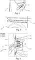
- FIG. 7 shows a tool for tightening or loosening bolts, known in the art.
- FIG. 1 and FIG. 2 are pictures of a vehicle 1 with a slidable door 2 in a closed position.
- the slidable door 2 is guided in a rail 3 mounted to the outside of the vehicle 1.
- the slidable door 2 is attached to the vehicle using a mounting bracket 4 shown in FIG. 3 .
- the mounting bracket 4 is connected to a post 5 of the vehicle body, using a plurality of screws 6, in manners known per se in the art.
- the bracket 4 is highly accessible for adjusting the position of the slidable door 2 relative to the vehicle body 1.
- a design team changed the design of vehicle 1 (shown in FIG. 1 ), in particular by changing the mounting of the slidable door 2, to create the vehicle 11 (shown in FIG. 4 and FIG. 5 ) having a more elegant design.
- the vehicle 11 has a slidable door 12, which is guided by a guiding rail 13, but the guiding rail 13 is largely concealed by being incorporated at least partially into the bodywork of the vehicle 11.
- a bolt 18 needs to be adjusted after the slidable door 12 is mounted to the vehicle body.
- the mounting bracket 14 is no longer mounted to the outside of the post 15, but is accommodated in a cavity 17 formed by a hollow object 16, e.g. a tub-shaped object 16 mounted to the vehicle body.
- the clearance or spacing ⁇ z between an upper wall or wall section of the hollow object 16, e.g. tub-shaped object 16, and the bolt head 18 (in a longitudinal direction of the bolt) is very small, for example only about 6 mm
- the clearance or spacing ⁇ y between a side wall of the hollow object 16, e.g. tub-shaped object 16, and the bolt head 18 (in a radial direction of the bolt) is also very small, for example only about 6 mm.
- the inventors came to the idea of making a new tool to address this specific problem, contrary to the opinion of the tool experts. Quite surprisingly they found a satisfactory solution, taking due account of the small dimensions involved, the forces or torque involved, and taking into consideration that the tool must be suitable for use in an automotive production environment, where the tool is used many times per day.
- the inventors started from an existing tool 20, illustrated in FIG. 7 , which at the time of drafting this application.
- the inventors replaced the existing front end by a newly developed front end, and thereby created the new tightening device 21 shown in FIG. 8 .
- the new tightening device 21 has a different front end.
- FIG. 9 shows the front end of the tightening device 21 of FIG. 8 in more detail.
- the most relevant parts for the purpose of the present invention are the ring gear 23 and the housing for accommodating the ring gear 23 and one or more intermediate gears.
- FIG. 10 is a schematic view of an exemplary set of gears 23-26 as may be used in the tightening device 21 of FIG. 9 . It is noted that FIG. 10 is only intended to explain how the invention works. As will be appreciated by the skilled person, several details are omitted from this figure, such as for example bushings, screws and/or bolts, etc.
- FIG. 11 is a schematic view of a portion of the housing of FIG. 9 for accommodating at least some of the gears 23-26.
- the housing may comprise an upper part and a lower part.
- FIG. 12 shows a portion of the tightening device 21 of FIG. 9 in further detail, and in side view. It should be appreciated, that the thickness H of the housing portion is unusually thin for this kind of applications.
- the tightening device 21 comprises a ring gear 23 having outer teeth for engagement with a driving gear set 24, 25, 26 (see FIG. 10 ), and having inner ridges 28 for engagement with an outer periphery of a head of a bolt 18 (see FIG. 6 ), e.g. a hexagonal bolt head.
- the tightening device 21 further comprises the driving gear set comprising a driving gear 26 and at least one intermediate gear 24 located between the driving gear 26 and the ring gear 23.
- the ring gear 23 and the at least one intermediate gear 24 have substantially the same outer diameter, but that is not absolutely required.
- the ring gear 23 and the at least one intermediate gear 24 are accommodated in a metal housing, preferably comprising a half-disk-shaped housing portion 29 and a rectangular beam-shaped housing portion 30.
- the length of the rectangular beam-shaped housing portion 30 depends on the number of intermediate gears 24, 25.
- the half-disk-shaped housing portion 29 and the rectangular beam-shaped housing portion 30 have a height H of at most 5 mm, which is extremely small for this kind of applications, namely an automotive production environment.
- the length of the half-disk-shaped housing portion 29 and the rectangular beam-shaped housing portion 30 is indicated by reference sign L in FIG. 11 and 12 .
- the half-disk-shaped housing portion 29 and the rectangular beam-shaped housing portion 30 are furthermore made of tempered steel having a hardness in the range from 40 to 45 HRC, preferably equal to about 40 HRC.
- the housing portion 29 preferably has two circular openings aligned with opposite sides of the ring gear 23 for allowing the bolt head 18 to pass through the housing to engage with the ridges of the ring gear 23.
- the number of ridges 28 of the ring gear 23 may be six, or preferably be twelve.
- a driving gear set with only a single intermediate gear 24 may suffice.
- the ring gear 23 and the intermediate gear 24 and the driving gear 26 are arranged collinear, i.e. the centres of the ring gear 23, the intermediate gear 24 and the driving gear 26 are all arranged on one single virtual line.
- the driving gear set may comprise at least two intermediate gears 24, 25 (as illustrated in FIG. 10 ).
- the ring gear 23 and the two intermediate gears 24 and 25 and optionally also the driving gear 26 are arranged in a collinear fashion, too.
- the rectangular beam-shaped housing portion 30 has a constant width W.
- the width W is preferably smaller than the sum of the outer diameter of the ring gear 23 plus 10 mm (thus plus 5 mm on either side).
- a tightening device 21 is described above, but the present invention also provides a method for adjusting the position of a slidable door 12 mounted to a vehicle body 11 (see. FIG. 4 to 6 ) by means of a bracket 14 comprising a bolt 18 to be adjusted, where the bracket 14 is accommodated inside a hollow space 17 defined by a hollow object 16, e.g. a tub-shaped object 16, mounted to the vehicle body 11, the hollow object 16 having a size and shape for accommodating the bracket 14.
- the position of the slidable door 12 can be adjusted by applying the following steps:
- the bracket 14 is mounted inside the hollow space 17 defined by the hollow object 16, e.g. tub-shaped object 16, with a first clearance ⁇ z equal to about 6 mm between a first (e.g. upper) wall or wall section of the hollow object 16 and the bolt head 18 in a longitudinal direction Z of the bolt, and with a second clearance ⁇ y equal to about 6 mm between a second (e.g. side) wall or wall section of the hollow object 16 and the bolt head 18 in a radial direction Y of the bolt.
- first clearance ⁇ z equal to about 6 mm between a first (e.g. upper) wall or wall section of the hollow object 16 and the bolt head 18 in a longitudinal direction Z of the bolt
- a second clearance ⁇ y equal to about 6 mm between a second (e.g. side) wall or wall section of the hollow object 16 and the bolt head 18 in a radial direction Y of the bolt.
- step iv) comprises: exerting a torque on the ring gear 23 lower than 11 Nm, for example a torque of at most 10 Nm, by, for example, an electrical motor (not shown) arranged inside the tightening device 21.
Landscapes
- Engineering & Computer Science (AREA)
- Mechanical Engineering (AREA)
- Power-Operated Mechanisms For Wings (AREA)
Abstract
Description
- The present invention relates in general to a tightening device and to mounting a slidable door of a vehicle. The present invention relates more in particular to a tightening device for use in an automotive production environment for tightening or loosening a bolt arranged in a cavity with only very limited clearance, and to a method of adjusting a position of a slidable door using such a tightening device.
- Motor vehicles with a slidable door are known in the art. The door is typically mounted by means of a bracket attached to the vehicle body. The bracket typically has an adjustment means in the form of a bolt which needs to be tightened or loosened for fine-positioning the door relative to the vehicle body.
- Tightening devices for tightening or loosening bolts are known in the art, and come in many different shapes and sizes. Some of these devices are pneumatic, some of these devices have an electrical motor which can be configured to exert a specified maximum torque. From a mechanical point of view, these devices are typically made for approaching bolts from the top, but such devices can only be used if there is sufficient space to position the device relative to the bolt head.
-
GB 1,083,205 A -
KR 20080033655 A -
AU 2013203755 B2 -
FR 2 915 122 B1 - However, most prior art tightening devices require a space of at least about 10 cm around the bolt head.
- The present invention has the object to provide a tightening tool or tightening device suitable for use in an automotive production environment for tightening or loosening a bolt arranged in a space with only a limited clearance.
- It is a particular object of embodiments of the present invention to provide such a tightening tool suitable for tightening or loosening a bolt arranged inside a hollow object having a plurality of walls or wall sections such that the spacing or clearance between the bolt head and two of the walls or wall sections is only about 6 mm in a longitudinal direction of the bolt and is only about 6 mm in a radial direction of the bolt.
- It is a particular object of embodiments of the present invention to provide such a tightening tool which is electrically powered.
- The present invention also has the object to provide a method for adjusting a position of a slidable door mounted to a vehicle, involving tightening and/or loosening a bolt arranged inside the hollow object described above.
- These objects are achieved by a tightening device having the features of claim 1, and by a method of adjusting a slidable door of a vehicle having the features of
claim 6. Further, particularly advantageous embodiments of the invention are disclosed in the dependent claims. - It should be noted that the individual features listed in the description below can be combined in any technically meaningful way with each other and show further embodiments of the invention. The description of the invention is additionally characterized and specified particularly in connection with the figures.
- In an advantageous embodiment, the present invention discloses a tightening device for use in an automotive production environment for tightening and/or loosening a bolt located inside a cavity with limited clearance between the bolt head and walls or wall sections of the cavity, the tightening device comprising: a ring gear having outer teeth for engaging a driving gear set, and having inner ridges for engaging an outer periphery of a head of the bolt to be tightened or loosened; the driving gear set comprising a driving gear and at least one intermediate gear, the at least one intermediate gear being located between the driving gear and the ring gear; the ring gear and the at least one intermediate gear being accommodated in a metal housing comprising a half-disk-shaped housing portion and a rectangular-beam-shaped housing portion; the half-disk-shaped housing portion and the rectangular beam-shaped housing portion having a height of at most 5 mm, and being made of tempered steel having a hardness in the range from 40 to 45 HRC, for example equal to about 40 HRC.
- It is an advantage of using a ring gear and a driving gear set that a chain of gears can be formed for exerting a torque at a distal location, offset from the axis of the driving gear.
- It is a further advantage of using a metal housing having the dimensions and shape described above, because it allows to insert the metal housing in a very small area.
- It is a further advantage of using a tempered metal housing having a hardness of 40 to 45 HRC, because it increases the resistance of the housing to withstand deformation during use.
- It is a further advantage of using a rectangular-beam-shaped housing portion (rather than a tapered or trapezoidal housing portion) that it can be used to fasten or loosen a bolt arranged within a space leaving only a small clearance in the longitudinal direction of the bolt, but also a small clearance in a radial direction of the bolt.
- According to a further advantageous embodiment of the present invention, the tightening device further comprises an electrical motor operatively connected to the driving gear set and configured to exert a torque less than 12 Nm, for example a torque less than 11 Nm, for example a torque equal to about 10 Nm.
- It is an advantage of using a relatively low torque in that the tightening device is capable of withstanding the forces and tensions exerted on the metal housing, but is still capable of reliably fastening or loosening the bolt of the bracket of the slidable door.
- According to a further advantageous embodiment of the present invention, the driving gear set comprises at least two intermediate gears between the driving gear and the ring gear, each of the intermediate gears being collinear with the ring gear and the driving gear, i.e. the centres of the ring gear, the intermediate gears and the driving gear are all arranged on one single virtual line which allows for a narrow arrangement of the gears.
- It is an advantage of using at least two intermediate gears because it allows the ring gear to be offset from the driving gear by a larger distance, e.g. in case the intermediate gears have the same diameter, over a distance of at least 2x this diameter.
- According to a further advantageous embodiment of the present invention, the number of ridges of the ring gear is at least twelve.
- While a bolt head typically has only six sides, it is an advantage of using a ring gear having at least twelve ridges. This allows easier engagement of the ring gear and the bolt head, and may provide more accurate adjustment.
- According to a further advantageous embodiment of the present invention, the rectangular beam-shaped housing portion has a constant width; and the width is smaller than the sum of an outer diameter of the ring gear plus 10 mm.
- According to another advantageous embodiment of the present invention, the present invention discloses a method of adjusting a position of a slidable door mounted to a vehicle body by means of a bracket comprising a bolt to be adjusted, the bracket being accommodated inside a cavity of a hollow object having a plurality of walls or wall sections, the hollow object being mounted to the vehicle body; the method comprising the steps of: i) providing a tightening device as described above; ii) inserting the half-disk-shaped housing portion and at least a part of the rectangular beam-shaped housing portion of the tightening device inside the hollow object between a first wall or first wall section of the hollow object and the bolt head; iii) moving the tightening device such that the ring gear engages a head of the bolt; iv) tightening or loosening the bolt of the bracket by exerting torque on the driving gear.
- According to a further advantageous embodiment of the present invention, the bracket is mounted inside the cavity defined by the hollow object with a first clearance Δz equal to about 6 mm between a first wall or first wall section of the hollow object and the head of the bolt in a longitudinal direction of the bolt.
- According to a further advantageous embodiment of the present invention, the bracket is mounted inside the cavity defined by the hollow object with a second clearance Δy equal to about 6 mm between a second wall or second wall section of the hollow object and the head of the bolt in a radial direction of the bolt.
- According to a further advantageous embodiment of the present invention, the tightening device further comprises an electrical motor; and step iv) comprises: the motor exerting a torque on the ring gear lower than 11 Nm.
- According to a further advantageous embodiment of the present invention, a wall or wall portion of the hollow object comprises a groove or a recess for guiding the beam-shaped housing portion of the tightening tool towards the head of the bolt.
- It is an advantage of providing a hollow, e.g. tub-shaped, object comprising a wall or wall section having a groove or recess because it helps to find the bolt head easier and faster, especially if the bolt head cannot be seen during operation of the tightening device.
- According to a further advantageous embodiment of the present invention, the hollow object is made of plastic.
- It is an advantage of providing a hollow, e.g. tub-shaped, object made of plastic, because it is somewhat flexible and can absorb shocks, for example caused by contact between the half-disk-shaped housing portion of the tightening device and the hollow object, thereby reducing the risk of inadvertently damaging the tightening device.
-
FIG. 7 shows a tool for tightening or loosening bolts, known in the art. - Further features and advantages of the present invention will become apparent from the following description of a non-limiting embodiment of the invention which will be explained below with reference to the drawing, wherein:
- FIG. 1
- is a rear view of a first vehicle with a slidable door which is closed. A guiding rail for guiding the slidable door is protruding from a side of the vehicle body and is clearly visible.
- FIG. 2
- is a side view of a portion of the vehicle of
FIG. 1 . - FIG. 3
- shows a portion of the slidable door of
FIG. 1 in a partially open state, seen from the inside of the vehicle. Also visible is a first mounting bracket connected to a post of the vehicle body. - FIG. 4
- is a rear view of a second vehicle, which can be seen as an improved version of the vehicle of
FIG. 1 . The second vehicle also has a slidable door and a guiding rail for guiding the slidable door, but the guiding rail is largely hidden, which is more elegant. - FIG. 5
- is a side view of the vehicle of
FIG. 4 . - FIG. 6
- shows a portion of the slidable door of
FIG. 4 in a partially open state, seen from the inside of the vehicle. Also visible is a second mounting bracket arranged inside the cavity defined by a tub-shaped object connected to a post of the vehicle body. It is a challenge to reach the bolt head (pointed to by a black arrow) for adjusting the position of the slidable door. - FIG. 8
- shows an embodiment of a tightening device according to the present invention, as a modification of the tool shown in
FIG. 7 . - FIG. 9
- is an enlarged perspective view of a portion of the tightening device shown in
FIG. 8 . - FIG. 10
- is a schematic view of an exemplary set of gears as may be used in the tightening device of
FIG. 9 . - FIG. 11
- is a schematic view of a portion of the housing of the tightening device of
FIG. 9 . - FIG. 12
- is an enlarged side view of a portion of the tightening device of
FIG. 9 . The thickness of the housing portion is ultra-thin for this kind of applications. - In the various figures, equivalent elements with respect to their function are always provided with the same reference numerals so that these elements are usually described only once.
-
FIG. 1 and FIG. 2 are pictures of a vehicle 1 with aslidable door 2 in a closed position. Theslidable door 2 is guided in arail 3 mounted to the outside of the vehicle 1. - The
slidable door 2 is attached to the vehicle using a mounting bracket 4 shown inFIG. 3 . The mounting bracket 4 is connected to apost 5 of the vehicle body, using a plurality ofscrews 6, in manners known per se in the art. The bracket 4 is highly accessible for adjusting the position of theslidable door 2 relative to the vehicle body 1. - A design team changed the design of vehicle 1 (shown in
FIG. 1 ), in particular by changing the mounting of theslidable door 2, to create the vehicle 11 (shown inFIG. 4 and FIG. 5 ) having a more elegant design. Thevehicle 11 has aslidable door 12, which is guided by a guidingrail 13, but the guidingrail 13 is largely concealed by being incorporated at least partially into the bodywork of thevehicle 11. - However, the design team also changed the mounting bracket. While the original mounting bracket 4 (see
FIG. 3 ) is easily accessible, a mounting bracket 14 (seeFIG. 6 ) of the newly designedvehicle 11 is concealed, which again is more elegant, but created a technical challenge for the production team, as can be appreciated fromFIG. 6 . - In order to fine-tune the positioning of the
slidable door 12, abolt 18 needs to be adjusted after theslidable door 12 is mounted to the vehicle body. However, in the new design, the mountingbracket 14 is no longer mounted to the outside of thepost 15, but is accommodated in acavity 17 formed by ahollow object 16, e.g. a tub-shapedobject 16 mounted to the vehicle body. - As can be seen in
FIG. 6 , the clearance or spacing Δz between an upper wall or wall section of thehollow object 16, e.g. tub-shapedobject 16, and the bolt head 18 (in a longitudinal direction of the bolt) is very small, for example only about 6 mm, and the clearance or spacing Δy between a side wall of thehollow object 16, e.g. tub-shapedobject 16, and the bolt head 18 (in a radial direction of the bolt) is also very small, for example only about 6 mm. - While it may be possible to fasten or loosen the
bolt head 18 manually with an openended wrench, it is not an acceptable or preferred solution for an automotive production environment, because it is very time consuming, and because it does not allow to control the torque exerted on thebolt head 18 accurately. - Well-known and highly reputable professional tool vendors were consulted, which expressed the opinion, based on decades of experience, that it is impossible to build a tool for tightening or loosening a
bolt 18 positioned in acavity 17 with such a small clearance Δy, Δz in radial and longitudinal direction. - Rather than further adjusting the design of the vehicle, the inventors came to the idea of making a new tool to address this specific problem, contrary to the opinion of the tool experts. Quite surprisingly they found a satisfactory solution, taking due account of the small dimensions involved, the forces or torque involved, and taking into consideration that the tool must be suitable for use in an automotive production environment, where the tool is used many times per day.
- Specifically, the inventors started from an existing
tool 20, illustrated inFIG. 7 , which at the time of drafting this application. The inventors replaced the existing front end by a newly developed front end, and thereby created thenew tightening device 21 shown inFIG. 8 . Thus, simply stated, thenew tightening device 21 has a different front end. - Before discussing a preferred embodiment of the front end in more detail, first it will be explained at high level what is shown in
FIG. 9 to FIG. 12 . -
FIG. 9 shows the front end of the tighteningdevice 21 ofFIG. 8 in more detail. The most relevant parts for the purpose of the present invention are thering gear 23 and the housing for accommodating thering gear 23 and one or more intermediate gears. -
FIG. 10 is a schematic view of an exemplary set of gears 23-26 as may be used in the tighteningdevice 21 ofFIG. 9 . It is noted thatFIG. 10 is only intended to explain how the invention works. As will be appreciated by the skilled person, several details are omitted from this figure, such as for example bushings, screws and/or bolts, etc. -
FIG. 11 is a schematic view of a portion of the housing ofFIG. 9 for accommodating at least some of the gears 23-26. In practice, the housing may comprise an upper part and a lower part. -
FIG. 12 shows a portion of the tighteningdevice 21 ofFIG. 9 in further detail, and in side view. It should be appreciated, that the thickness H of the housing portion is unusually thin for this kind of applications. - With reference to
FIG. 9 to FIG. 12 , the following more detailed description can now be understood. - The tightening
device 21 comprises aring gear 23 having outer teeth for engagement with a driving gear set 24, 25, 26 (seeFIG. 10 ), and havinginner ridges 28 for engagement with an outer periphery of a head of a bolt 18 (seeFIG. 6 ), e.g. a hexagonal bolt head. - The tightening
device 21 further comprises the driving gear set comprising adriving gear 26 and at least oneintermediate gear 24 located between the drivinggear 26 and thering gear 23. Preferably thering gear 23 and the at least oneintermediate gear 24 have substantially the same outer diameter, but that is not absolutely required. - The
ring gear 23 and the at least oneintermediate gear 24 are accommodated in a metal housing, preferably comprising a half-disk-shapedhousing portion 29 and a rectangular beam-shapedhousing portion 30. The length of the rectangular beam-shapedhousing portion 30 depends on the number ofintermediate gears - According to an important aspect of the present invention, the half-disk-shaped
housing portion 29 and the rectangular beam-shapedhousing portion 30 have a height H of at most 5 mm, which is extremely small for this kind of applications, namely an automotive production environment. The length of the half-disk-shapedhousing portion 29 and the rectangular beam-shapedhousing portion 30 is indicated by reference sign L inFIG. 11 and 12 . - The half-disk-shaped
housing portion 29 and the rectangular beam-shapedhousing portion 30 are furthermore made of tempered steel having a hardness in the range from 40 to 45 HRC, preferably equal to about 40 HRC. - The
housing portion 29 preferably has two circular openings aligned with opposite sides of thering gear 23 for allowing thebolt head 18 to pass through the housing to engage with the ridges of thering gear 23. - The number of
ridges 28 of thering gear 23 may be six, or preferably be twelve. - Depending on how deep the
bolt head 18 is located inside the cavity (in the X-direction ofFIG. 6 ), a driving gear set with only a singleintermediate gear 24 may suffice. In this case thering gear 23 and theintermediate gear 24 and thedriving gear 26 are arranged collinear, i.e. the centres of thering gear 23, theintermediate gear 24 and thedriving gear 26 are all arranged on one single virtual line. - In another embodiment, the driving gear set may comprise at least two
intermediate gears 24, 25 (as illustrated inFIG. 10 ). In this case thering gear 23 and the twointermediate gears driving gear 26 are arranged in a collinear fashion, too. - As suggested by
FIG. 11 , preferably the rectangular beam-shapedhousing portion 30 has a constant width W. The width W is preferably smaller than the sum of the outer diameter of thering gear 23 plus 10 mm (thus plus 5 mm on either side). - A tightening
device 21 is described above, but the present invention also provides a method for adjusting the position of aslidable door 12 mounted to a vehicle body 11 (see.FIG. 4 to 6 ) by means of abracket 14 comprising abolt 18 to be adjusted, where thebracket 14 is accommodated inside ahollow space 17 defined by ahollow object 16, e.g. a tub-shapedobject 16, mounted to thevehicle body 11, thehollow object 16 having a size and shape for accommodating thebracket 14. - The position of the
slidable door 12 can be adjusted by applying the following steps: - i) providing a
tightening device 21 described above; - ii) inserting the half-disk-shaped
housing portion 29 and at least a part of the rectangular beam-shapedhousing portion 30 of the tighteningdevice 21 inside thehollow space 17 of thehollow object 16 between a first (e.g. upper) wall section of thehollow object 16 and thebolt head 18; - iii) moving (e.g. lowering) the
tightening device 21 such that thering gear 23 engages thebolt head 18; - iv) tightening or loosening the
bolt 18 of thebracket 14 by operating the tighteningdevice 21 to exert a torque on thedriving gear 26, and thus indirectly (via theintermediate gears 24 and/or 25) to exert a torque on thering gear 23. - In the specific example of
FIG. 6 , thebracket 14 is mounted inside thehollow space 17 defined by thehollow object 16, e.g. tub-shapedobject 16, with a first clearance Δz equal to about 6 mm between a first (e.g. upper) wall or wall section of thehollow object 16 and thebolt head 18 in a longitudinal direction Z of the bolt, and with a second clearance Δy equal to about 6 mm between a second (e.g. side) wall or wall section of thehollow object 16 and thebolt head 18 in a radial direction Y of the bolt. - Preferably the tightening or loosening is performed in a controlled manner, so as to exert a specific maximum torque on the
ring gear 23. Preferably step iv) comprises: exerting a torque on thering gear 23 lower than 11 Nm, for example a torque of at most 10 Nm, by, for example, an electrical motor (not shown) arranged inside the tighteningdevice 21. -
- 1
- first vehicle,
- 2
- slidable door,
- 3
- guiding rail,
- 4
- mounting bracket,
- 5
- post,
- 11
- second vehicle,
- 12
- slidable door,
- 13
- guiding rail,
- 14
- mounting bracket
- 15
- post,
- 16
- hollow object, e.g. tub-shaped object,
- 17
- hollow space,
- 18
- bolt or bolt head,
- 20
- (known) tightening tool,
- 21
- tightening device,
- 23
- ring gear,
- 24
- first intermediate gear,
- 25
- second intermediate gear,
- 26
- driving gear,
- 28
- ridges,
- 29
- half-disk-shaped housing portion,
- 30
- rectangular-beam-shaped housing portion.
Claims (11)
- A tightening device (21) for use in an automotive production environment for tightening and/or loosening a bolt (18) located inside a cavity (17) with limited clearance (Δy, Δz) between a head of the bolt and wall sections of the cavity, the tightening device (21) comprising:- a ring gear (23) having outer teeth for engaging a driving gear set (24, 25, 26) and having inner ridges (28) for engaging an outer periphery of a head of the bolt (18);- the driving gear set (24, 25, 26) comprising a driving gear (26) and at least one intermediate gear (24), the at least one intermediate gear (24) being located between the driving gear (26) and the ring gear (23);- the ring gear (23) and the at least one intermediate gear (24) being accommodated in a metal housing comprising a half-disk-shaped housing portion (29) and a rectangular-beam-shaped housing portion (30);- the half-disk-shaped housing portion and the rectangular beam-shaped housing portion having a height (H) of at most 5 mm, and being made of tempered steel having a hardness in the range from 40 to 45 HRC.
- A tightening device (21) according to claim 1,
further comprising an electrical motor operatively connected to the driving gear set and configured to exert a torque less than 12 Nm. - A tightening device (21) according to claim 1 or 2,
wherein the driving gear set (24, 25, 26) comprises at least two intermediate gears (24, 25) located between the driving gear (26) and the ring gear (23), each of the intermediate gears (24, 25) being collinear with the ring gear (23) and the driving gear (26). - A tightening device (21) according to any of the previous claims,
wherein the number of ridges (28) is at least twelve. - A tightening device (21) according to any of the previous claims,
wherein the rectangular beam-shaped housing portion (30) has a constant width (W); and
wherein the width (W) is smaller than the sum of an outer diameter of the ring gear (23) plus 10 mm. - Method of adjusting a position of a slidable door (12) mounted to a vehicle body (11) by means of a bracket (14) comprising a bolt (18) to be adjusted, the bracket (14) being accommodated inside a cavity (17) of a hollow object (16) having a plurality of wall sections, the hollow object (16) being mounted to the vehicle body (11);
the method comprising the steps of:i) providing a tightening device (21) according to any of the previous claims;ii) inserting the half-disk-shaped housing portion (29) and at least a part of the rectangular beam-shaped housing portion (30) of the tightening device (21) inside the hollow object (16) between a first wall section of the hollow object (16) and a head of the bolt (18);iii) moving the tightening device (21) such that the ring gear (23) engages the head of the bolt (18);iv) tightening or loosening the bolt (18) of the bracket (14) by exerting torque on the driving gear (26). - Method according to claim 6,
wherein the bracket (14) is mounted inside the cavity (17) defined by the hollow object (16) with a first clearance (Δz) equal to about 6 mm between a first wall section of the hollow object (16) and the head of the bolt (18) in a longitudinal direction (Z) of the bolt. - Method according to claim 6 or 7,
wherein the bracket (14) is mounted inside the cavity (17) defined by the hollow object (16) with a second clearance (Δy) equal to about 6 mm between a second wall section of the hollow object (16) and the head of the bolt (18) in a radial direction (Y) of the bolt (18). - Method according to any of the claims 6 to 8,
wherein the tightening device (21) further comprises an electrical motor;
and wherein step iv) comprises: the motor exerting a torque on the ring gear (23) lower than 11 Nm. - Method according to any of the claims 6 to 9,
wherein a wall section of the hollow object (16) comprises a groove or recess for guiding the beam-shaped housing portion (30) of the tightening tool (21) towards the head of the bolt (18). - Method according to any of the claims 6 to 10,
wherein the hollow object (16) is made of plastic.
Priority Applications (1)
| Application Number | Priority Date | Filing Date | Title |
|---|---|---|---|
| EP18155033.6A EP3520966B1 (en) | 2018-02-05 | 2018-02-05 | Tightening device and method of adjusting a slidable door of a vehicle |
Applications Claiming Priority (1)
| Application Number | Priority Date | Filing Date | Title |
|---|---|---|---|
| EP18155033.6A EP3520966B1 (en) | 2018-02-05 | 2018-02-05 | Tightening device and method of adjusting a slidable door of a vehicle |
Publications (2)
| Publication Number | Publication Date |
|---|---|
| EP3520966A1 true EP3520966A1 (en) | 2019-08-07 |
| EP3520966B1 EP3520966B1 (en) | 2024-08-07 |
Family
ID=61163528
Family Applications (1)
| Application Number | Title | Priority Date | Filing Date |
|---|---|---|---|
| EP18155033.6A Active EP3520966B1 (en) | 2018-02-05 | 2018-02-05 | Tightening device and method of adjusting a slidable door of a vehicle |
Country Status (1)
| Country | Link |
|---|---|
| EP (1) | EP3520966B1 (en) |
Cited By (1)
| Publication number | Priority date | Publication date | Assignee | Title |
|---|---|---|---|---|
| CN111975693A (en) * | 2020-07-06 | 2020-11-24 | 中车青岛四方机车车辆股份有限公司 | Wrench used in narrow space and application thereof |
Citations (9)
| Publication number | Priority date | Publication date | Assignee | Title |
|---|---|---|---|---|
| GB1083205A (en) | 1964-05-08 | 1967-09-13 | Bruno Stamm | Swing door |
| US4374480A (en) * | 1981-01-05 | 1983-02-22 | Diaz William J | Extension tool |
| US4735118A (en) * | 1986-05-02 | 1988-04-05 | Broemel Jr Lloyd F | Air ratchet adaptor |
| DE20318021U1 (en) * | 2003-11-21 | 2004-02-05 | Hazet-Werk Hermann Zerver Gmbh & Co. Kg | Adaptor for threaded fasteners in confined spaces has a shallow housing holding two meshing gears with connections for a square drive stub and a spanner grip for fasteners |
| KR20080033655A (en) | 2006-10-12 | 2008-04-17 | 현대자동차주식회사 | Center roller arm hinge assembly of sliding door for vehicle |
| FR2915122B1 (en) | 2007-04-18 | 2009-06-05 | Georges Renault Soc Par Action | SCREWING TOOL COMPRISING A WINDOW ADJUSTING WINDOW ADJUSTING WINDOW AND A WINDOW SEALING TRAP CAPABLE OF BEING ENCAPSED BY A MECHANISM WITH ACTUATING MEANS |
| GB2497594A (en) * | 2011-12-17 | 2013-06-19 | Christopher Sydney Winter | Wrench extender for nut threading in confined spaces |
| WO2014095517A1 (en) * | 2012-12-21 | 2014-06-26 | Atlas Copco Industrial Technique Ab | Power tool attachment part |
| AU2013203755B2 (en) | 2012-05-29 | 2016-05-12 | Ciilock Engineering Pty Ltd | Connection arrangements, pivots and mechanisms |
-
2018
- 2018-02-05 EP EP18155033.6A patent/EP3520966B1/en active Active
Patent Citations (9)
| Publication number | Priority date | Publication date | Assignee | Title |
|---|---|---|---|---|
| GB1083205A (en) | 1964-05-08 | 1967-09-13 | Bruno Stamm | Swing door |
| US4374480A (en) * | 1981-01-05 | 1983-02-22 | Diaz William J | Extension tool |
| US4735118A (en) * | 1986-05-02 | 1988-04-05 | Broemel Jr Lloyd F | Air ratchet adaptor |
| DE20318021U1 (en) * | 2003-11-21 | 2004-02-05 | Hazet-Werk Hermann Zerver Gmbh & Co. Kg | Adaptor for threaded fasteners in confined spaces has a shallow housing holding two meshing gears with connections for a square drive stub and a spanner grip for fasteners |
| KR20080033655A (en) | 2006-10-12 | 2008-04-17 | 현대자동차주식회사 | Center roller arm hinge assembly of sliding door for vehicle |
| FR2915122B1 (en) | 2007-04-18 | 2009-06-05 | Georges Renault Soc Par Action | SCREWING TOOL COMPRISING A WINDOW ADJUSTING WINDOW ADJUSTING WINDOW AND A WINDOW SEALING TRAP CAPABLE OF BEING ENCAPSED BY A MECHANISM WITH ACTUATING MEANS |
| GB2497594A (en) * | 2011-12-17 | 2013-06-19 | Christopher Sydney Winter | Wrench extender for nut threading in confined spaces |
| AU2013203755B2 (en) | 2012-05-29 | 2016-05-12 | Ciilock Engineering Pty Ltd | Connection arrangements, pivots and mechanisms |
| WO2014095517A1 (en) * | 2012-12-21 | 2014-06-26 | Atlas Copco Industrial Technique Ab | Power tool attachment part |
Cited By (1)
| Publication number | Priority date | Publication date | Assignee | Title |
|---|---|---|---|---|
| CN111975693A (en) * | 2020-07-06 | 2020-11-24 | 中车青岛四方机车车辆股份有限公司 | Wrench used in narrow space and application thereof |
Also Published As
| Publication number | Publication date |
|---|---|
| EP3520966B1 (en) | 2024-08-07 |
Similar Documents
| Publication | Publication Date | Title |
|---|---|---|
| KR102278862B1 (en) | Fastening concept for the play-free mounting of adjustment drives in a motor vehicle | |
| EP3520966B1 (en) | Tightening device and method of adjusting a slidable door of a vehicle | |
| EP1935698A1 (en) | Drive unit with propulsion and steering motor for the drive wheel of an industrial truck | |
| EP1953417B1 (en) | Worm wheel, gear, and electric motor | |
| US8033006B2 (en) | Method for mounting a thread-protecting element into a receiving thread and mounting spindle and a thread-protecting element therefore | |
| EP1510642B1 (en) | Device for the lateral adjustment of a window regulator for motor vehicles or similar | |
| DE102010049622A1 (en) | Electric drive unit for motor vehicle, particularly electric vehicle, has hub drive driving vehicle wheel, where vehicle wheel has wheel flange and rim consisting of rim well and two rim clamps | |
| CN106285206B (en) | driver and door and window structure | |
| US6952898B2 (en) | Guide rail adjusting device for a motor vehicle power window assembly | |
| DE102006046176A1 (en) | Fastening device e.g. for cogwheel bearing axis of gear, has case in which wheel bearing is defined on end of axis and has cap provided on housing | |
| US11458603B2 (en) | Tool for installing and removing a highly-torqued fastener | |
| JP6560867B2 (en) | Screw jack | |
| WO2014005173A1 (en) | Clamp | |
| JP5168922B2 (en) | Vehicle door structure | |
| CN105715772B (en) | Position adjustment drive, method for producing the same, and mechanism for the same in a motor vehicle | |
| DE202007007032U1 (en) | Fastening arrangement for fastening a drive unit of a cable window lifter for motor vehicles to a plate-shaped support and motor vehicle door with selbiger | |
| DE102007009852A1 (en) | Adjustment device for pivoting headlamp component, has linear drive, which has pull rod sliding along linear axis and bearing element is provided by which linear drive is supported such that it is rotating around rotary axis | |
| EP1520742B1 (en) | Device for lateral regulation of a window power device for motor vehicles | |
| KR20060083638A (en) | Tilting ass'y of steering coulmn for vehicles | |
| JP6181679B2 (en) | Screw jack | |
| DE202005004545U1 (en) | Electromotor mounting device e.g. for motor vehicle adjustment or actuating device, has integrated support element which is fixed into vehicle door frame | |
| CN215919155U (en) | Perforating machine for opposite-penetrating metal pipe | |
| US20240291351A1 (en) | Pinion-equipped motor and gear mechanism provided with pinion-equipped motor | |
| DE102004007517A1 (en) | Windscreen wiper device, in particular for a motor vehicle | |
| EP1375960A3 (en) | Drive unit with gear with a socket |
Legal Events
| Date | Code | Title | Description |
|---|---|---|---|
| PUAI | Public reference made under article 153(3) epc to a published international application that has entered the european phase |
Free format text: ORIGINAL CODE: 0009012 |
|
| STAA | Information on the status of an ep patent application or granted ep patent |
Free format text: STATUS: THE APPLICATION HAS BEEN PUBLISHED |
|
| AK | Designated contracting states |
Kind code of ref document: A1 Designated state(s): AL AT BE BG CH CY CZ DE DK EE ES FI FR GB GR HR HU IE IS IT LI LT LU LV MC MK MT NL NO PL PT RO RS SE SI SK SM TR |
|
| AX | Request for extension of the european patent |
Extension state: BA ME |
|
| STAA | Information on the status of an ep patent application or granted ep patent |
Free format text: STATUS: REQUEST FOR EXAMINATION WAS MADE |
|
| 17P | Request for examination filed |
Effective date: 20200207 |
|
| RBV | Designated contracting states (corrected) |
Designated state(s): AL AT BE BG CH CY CZ DE DK EE ES FI FR GB GR HR HU IE IS IT LI LT LU LV MC MK MT NL NO PL PT RO RS SE SI SK SM TR |
|
| STAA | Information on the status of an ep patent application or granted ep patent |
Free format text: STATUS: EXAMINATION IS IN PROGRESS |
|
| 17Q | First examination report despatched |
Effective date: 20210413 |
|
| STAA | Information on the status of an ep patent application or granted ep patent |
Free format text: STATUS: EXAMINATION IS IN PROGRESS |
|
| P01 | Opt-out of the competence of the unified patent court (upc) registered |
Effective date: 20230620 |
|
| GRAP | Despatch of communication of intention to grant a patent |
Free format text: ORIGINAL CODE: EPIDOSNIGR1 |
|
| STAA | Information on the status of an ep patent application or granted ep patent |
Free format text: STATUS: GRANT OF PATENT IS INTENDED |
|
| INTG | Intention to grant announced |
Effective date: 20240524 |
|
| GRAS | Grant fee paid |
Free format text: ORIGINAL CODE: EPIDOSNIGR3 |
|
| GRAA | (expected) grant |
Free format text: ORIGINAL CODE: 0009210 |
|
| STAA | Information on the status of an ep patent application or granted ep patent |
Free format text: STATUS: THE PATENT HAS BEEN GRANTED |
|
| AK | Designated contracting states |
Kind code of ref document: B1 Designated state(s): AL AT BE BG CH CY CZ DE DK EE ES FI FR GB GR HR HU IE IS IT LI LT LU LV MC MK MT NL NO PL PT RO RS SE SI SK SM TR |
|
| REG | Reference to a national code |
Ref country code: GB Ref legal event code: FG4D |
|
| REG | Reference to a national code |
Ref country code: CH Ref legal event code: EP |
|
| REG | Reference to a national code |
Ref country code: IE Ref legal event code: FG4D |
|
| REG | Reference to a national code |
Ref country code: DE Ref legal event code: R096 Ref document number: 602018072666 Country of ref document: DE |