EP3520878B1 - Filter element and use of such a filter element - Google Patents
Filter element and use of such a filter element Download PDFInfo
- Publication number
- EP3520878B1 EP3520878B1 EP18154621.9A EP18154621A EP3520878B1 EP 3520878 B1 EP3520878 B1 EP 3520878B1 EP 18154621 A EP18154621 A EP 18154621A EP 3520878 B1 EP3520878 B1 EP 3520878B1
- Authority
- EP
- European Patent Office
- Prior art keywords
- filter
- filter element
- frame
- element according
- filter layer
- Prior art date
- Legal status (The legal status is an assumption and is not a legal conclusion. Google has not performed a legal analysis and makes no representation as to the accuracy of the status listed.)
- Active
Links
Images

Classifications
-
- B—PERFORMING OPERATIONS; TRANSPORTING
- B01—PHYSICAL OR CHEMICAL PROCESSES OR APPARATUS IN GENERAL
- B01D—SEPARATION
- B01D46/00—Filters or filtering processes specially modified for separating dispersed particles from gases or vapours
- B01D46/10—Particle separators, e.g. dust precipitators, using filter plates, sheets or pads having plane surfaces
-
- B—PERFORMING OPERATIONS; TRANSPORTING
- B01—PHYSICAL OR CHEMICAL PROCESSES OR APPARATUS IN GENERAL
- B01D—SEPARATION
- B01D46/00—Filters or filtering processes specially modified for separating dispersed particles from gases or vapours
- B01D46/0002—Casings; Housings; Frame constructions
-
- B—PERFORMING OPERATIONS; TRANSPORTING
- B01—PHYSICAL OR CHEMICAL PROCESSES OR APPARATUS IN GENERAL
- B01D—SEPARATION
- B01D46/00—Filters or filtering processes specially modified for separating dispersed particles from gases or vapours
- B01D46/0027—Filters or filtering processes specially modified for separating dispersed particles from gases or vapours with additional separating or treating functions
- B01D46/0036—Filters or filtering processes specially modified for separating dispersed particles from gases or vapours with additional separating or treating functions by adsorption or absorption
-
- B—PERFORMING OPERATIONS; TRANSPORTING
- B01—PHYSICAL OR CHEMICAL PROCESSES OR APPARATUS IN GENERAL
- B01D—SEPARATION
- B01D46/00—Filters or filtering processes specially modified for separating dispersed particles from gases or vapours
- B01D46/10—Particle separators, e.g. dust precipitators, using filter plates, sheets or pads having plane surfaces
- B01D46/12—Particle separators, e.g. dust precipitators, using filter plates, sheets or pads having plane surfaces in multiple arrangements
-
- B—PERFORMING OPERATIONS; TRANSPORTING
- B01—PHYSICAL OR CHEMICAL PROCESSES OR APPARATUS IN GENERAL
- B01D—SEPARATION
- B01D46/00—Filters or filtering processes specially modified for separating dispersed particles from gases or vapours
- B01D46/56—Filters or filtering processes specially modified for separating dispersed particles from gases or vapours with multiple filtering elements, characterised by their mutual disposition
- B01D46/62—Filters or filtering processes specially modified for separating dispersed particles from gases or vapours with multiple filtering elements, characterised by their mutual disposition connected in series
- B01D46/64—Filters or filtering processes specially modified for separating dispersed particles from gases or vapours with multiple filtering elements, characterised by their mutual disposition connected in series arranged concentrically or coaxially
Definitions
- the invention relates to a filter element for filtering according to the preamble of claim 1 and the use of a filter element according to claim 12.
- the cabin air filter element comprises an adsorption filter layer with activated carbon, a fine filter layer, in particular for separating aerosols, and a circumferential seal for separating the unfiltered side from the clean side when installed in a filter housing.
- the cabin air filter element has an injection-molded plastic frame, which can either be prefabricated and accommodates the partial filter elements that are glued or welded in the frame.
- the frame can be designed as a pointed frame, which is formed by inserting the partial filter elements into a mold and then overmolding them with an injection molding frame, the material being permanently bonded to the partial filter elements when it hardens.
- a disadvantage of such a filter element is the high Effort and are the high costs involved in manufacturing the injection molded frame. For each frame size and frame shape, special injection molds must be kept, which are expensive to manufacture. A short-term adaptation of the shape of the frame and thus of the filter element as well as the production of filter elements in small batches are not economically feasible.
- the US 6,406,509 B1 , JP 2003 088718 A and DE 201 01 237 U1 each show a frame for a pleated filter layer.
- the frame is composed of extruded profile strips.
- the filter layer can be glued into the frame for better sealing.
- the object of the present invention is to create a filter element for filtering indoor air which at least reduces the disadvantages of the prior art, has a simple structure and enables simple installation in a housing. Another task is to be able to manufacture the filter element in a wide variety of sizes in small batches.
- the filter element according to the invention is used to filter and purify indoor air and has at least three filter layers, the filter layers being arranged in a frame. An area is provided in the frame for each filter layer.
- the frame is advantageously composed of extruded profile strips. So the frame is not injection molded. This has the advantage that mechanically stable filter elements of different sizes can be manufactured quickly and cost-effectively. According to the dimensions of the frame, the profile strips are cut to length and placed together. Because the two, three or more filter layers are combined in one filter element, no additional seal has to be installed between the filter layers when it is installed. This enables the filter element to be installed quickly and easily in a housing.
- the profile strips can be made in particular from plastic, in particular from ABS, PP or PA, or aluminum. These materials combine good extrudability with low weight and high stability at the same time.
- the first filter layer is designed as a prefilter
- the second filter layer as a fine filter, which can also be referred to as an aerosol filter
- the third filter layer as an adsorption filter.
- the prefilter and the fine filter can be designed, for example, as a pleated fold pack, also referred to as a fold pack, made of organic and / or inorganic nonwoven fabric and the adsorption filter, for example, as a filter body made of activated carbon or with an activated carbon coating.
- the fine filter as a HEPA filter, i.e. H. designed as a high-efficiency pariculate air filter.
- each profile strip between the second and third filter layer for example between the fine filter and the adsorption filter, has an inwardly protruding shoulder for the airtight separation of the second from the third filter layer in the area of the frame.
- each profile strip has in the area of the second filter layer, e.g. of the fine filter has at least one inwardly directed ridge that is raised in relation to the surface of the profile strip, in particular of low height, for receiving adhesive between the second filter layer and the profile strip. Thanks to the webs, the adhesive can flow well under the second filter layer, which allows the second filter layer to be bonded securely and leak-free in accordance with EN1822 and avoids bypasses in the area of the fine filter.
- each of its profile strips has an, optionally further, outwardly protruding shoulder, these shoulders together forming a circumferential flange of the filter element.
- the flange can be used for a defined assembly of the filter element in a housing. It is considered to be particularly advantageous and therefore preferred if a seal, for example seamlessly foamed in and completely encircling the frame, is attached to the flange for sealing the filter element from a housing into which the filter element is inserted.
- a seal for example seamlessly foamed in and completely encircling the frame
- the flange has a spacer, for example a protruding nose or a raised web, to limit the maximum seal compression in the assembled state.
- the spacer is located on the same side as the seal on the flange.
- the seal can be destroyed by excessive This prevents compression and ensures the functionality of the seal.
- the profile strips are connected to the frame with corner connectors that can be plugged into the profile strips. As a result, the frame can be assembled safely and stably in a simple manner without welding, screwing or riveting.
- the invention also relates to the use of a filter element as described above as a cabin air filter element for filtering and cleaning the cabin air in a vehicle which is subject to increased pollution, in particular in a utility vehicle, a heavy goods vehicle or an off-road vehicle.
- the vehicles can be, for example, trucks, construction machinery, rollers, tracked vehicles, road milling machines, bulldozers, loaders, excavators, cranes, harvesting machines, agricultural machines, combine harvesters, forage harvesters, tractors, self-propelled field sprayers or forest vehicles.
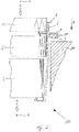
- FIG. 1 shows the structure of the filter element 100.
- the filter element 100 has a frame 4, which receives a first filter layer 1, a second filter layer 2 and a third filter layer 3. Air is - as shown by the arrows - transported from the environment, from a raw gas side a through the three filter layers 1, 2, 3 into the interior to a clean gas side b, where it is filtered.
- the first filter layer 1 is designed as a prefilter
- the second filter layer 2 as a fine filter, namely as a HEPA filter
- the third filter layer 3 as an adsorption filter with activated carbon.
- the frame 4 is composed of several extruded profile strips 5.
- the extruded profile guide has 5 grooves 12, which are used to insert corner connectors.
- the corner connectors are used to connect the individual profile strips and can be designed as thin, angular plates.
- the extruded profile strips 5 can be made of plastic or aluminum.
- the extruded profile strip 5 has a shoulder 6 protruding inward between the second filter layer 2 and the third filter layer 3 into the filter element 100, which is used to separate the second filter layer 2 from the third filter layer 3 in the area of the frame.
- a separation between the first filter layer 1 and the second filter layer 2 in the area of the frame 4 is effected by the upper edge surface of the extruded profile strip 5.
- At least the second filter layer 2 is glued into the frame 4 without leaks by means of adhesive 7, as shown.
- adhesive 7 for the meaning of "leak-free" reference is made to EN1822.
- the adhesive 7 can be well distributed in the area of the adhesive surface, ie the second filter layer 2 has a good flow of adhesive 7 behind it, several raised webs 10 are provided in the area of the second filter layer 2 on the extruded profile strip 5. These webs 10 also protrude into the interior of the filter element 100.
- the extruded profile strip 5 has an outwardly protruding paragraph 8. The paragraphs 8 of the assembled profile strips 5 form a circumferential flange of the filter element 100. On the underside of the shoulder 8, ie on the underside of the flange, a circumferential, foamed-on seal 9 is provided.
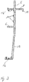
- the filter element 100 As in Figure 2 shown, mounted in a housing 200, the filter element 100 is pushed into the housing 200 in an insertion direction e. The filter element 100 is pushed into the housing 200 until the seal 9 creates a seal between the housing 200 and the filter element 100.
- at least one spacer 11 is attached to the shoulder 8, which limits the insertion movement during assembly and defines a maximum seal compression of the seal 9.
- the extruded profile strip 5 has an insertion bevel 13 (cf. Fig. 3 ).
Description
Die Erfindung betrifft ein Filterelement zum Filtern gemäß dem Oberbegriff von Anspruch 1 sowie die Verwendung eines Filterelements gemäß Anspruch 12.The invention relates to a filter element for filtering according to the preamble of claim 1 and the use of a filter element according to
Aus dem Stand der Technik sind unterschiedlichste Filterelemente zum Filtern von Innenraumluft bekannt. In der
Die
Aufgabe der vorliegenden Erfindung ist es, ein Filterelement zum Filtern von Innenraumluft zu schaffen, welches die Nachteile des Standes der Technik zumindest reduziert, einen einfachen Aufbau aufweist sowie einen einfachen Einbau in ein Gehäuse ermöglicht. Weitere Aufgabe ist es, das Filterelement auch in kleinen Chargen in unterschiedlichsten Größen herstellen zu können.The object of the present invention is to create a filter element for filtering indoor air which at least reduces the disadvantages of the prior art, has a simple structure and enables simple installation in a housing. Another task is to be able to manufacture the filter element in a wide variety of sizes in small batches.
Gelöst wird diese Aufgabe durch ein Filterelement mit den Merkmalen von Anspruch 1.This object is achieved by a filter element having the features of claim 1.
Das erfindungsgemäße Filterelement dient dem Filtern und Reinigen von Innenraumluft und besitzt mindestens drei Filterlagen, wobei die Filterlagen in einem Rahmen angeordnet sind. Für jede Filterlage ist dabei in dem Rahmen ein Bereich vorgesehen. In vorteilhafter Weise ist der Rahmen aus extrudierten Profilleisten zusammengesetzt. Der Rahmen ist also nicht spritzgegossen. Dies hat den Vorteil, dass so kostengünstig und schnell kundenindividuell mechanisch stabile Filterelemente unterschiedlicher Größe gefertigt werden können. Entsprechend den Abmaßen des Rahmens werden die Profilleisten abgelängt und aneinander gesetzt. Weil die zwei, drei oder mehr Filterlagen in dem einen Filterelement vereint sind, muss bei dessen Montage keine Abdichtung zwischen den Filterlagen zusätzlich eingebaut werden. Dadurch wird eine schnelle und einfache Montage des Filterelements in einem Gehäuse ermöglicht.The filter element according to the invention is used to filter and purify indoor air and has at least three filter layers, the filter layers being arranged in a frame. An area is provided in the frame for each filter layer. The frame is advantageously composed of extruded profile strips. So the frame is not injection molded. This has the advantage that mechanically stable filter elements of different sizes can be manufactured quickly and cost-effectively. According to the dimensions of the frame, the profile strips are cut to length and placed together. Because the two, three or more filter layers are combined in one filter element, no additional seal has to be installed between the filter layers when it is installed. This enables the filter element to be installed quickly and easily in a housing.
Die Profilleisten können dabei insbesondere aus Kunststoff, insbesondere aus ABS, PP oder PA, oder Aluminium gefertigt sein. Diese Materialien verbinden eine gute Extrudierbarkeit mit einem geringen Gewicht und gleichzeitig hoher Stabilität.The profile strips can be made in particular from plastic, in particular from ABS, PP or PA, or aluminum. These materials combine good extrudability with low weight and high stability at the same time.
Beim erfindungsgemäßen Filterelement ist die erste Filterlage als Vorfilter, die zweite Filterlage als Feinfilter, welcher auch als Aerosolfilter bezeichnet werden kann, und die dritte Filterlage als Adsorptionsfilter ausgebildet. Der Vorfilter und der Feinfilter können zum Beispiel als plissiertes Faltenpaket, auch als Faltenpack bezeichnet, aus organischem und/oder anorganischem Vliesstoff und der Adsorptionsfilter zum Beispiel als Filterkörper aus Aktivkohle oder mit einer Aktivkohlebeschichtung ausgeführt sein.In the filter element according to the invention, the first filter layer is designed as a prefilter, the second filter layer as a fine filter, which can also be referred to as an aerosol filter, and the third filter layer as an adsorption filter. The prefilter and the fine filter can be designed, for example, as a pleated fold pack, also referred to as a fold pack, made of organic and / or inorganic nonwoven fabric and the adsorption filter, for example, as a filter body made of activated carbon or with an activated carbon coating.
Als besonders vorteilhaft wurde erkannt, den Feinfilter als HEPA-Filter, d. h. als High-Efficieny-Pariculate-Air-Filter auszuführen.It was recognized as particularly advantageous to use the fine filter as a HEPA filter, i.e. H. designed as a high-efficiency pariculate air filter.
In erfindungsgemäßer Ausführung des Filterelements weist jede Profilleiste zwischen zweiter und dritter Filterlage, also z.B. zwischen Feinfilter und Adsorptionsfilter einen nach Innen hervorstehenden Absatz auf zur luftdichten Trennung der zweiten von der dritten Filterlage im Bereich des Rahmens.In the embodiment of the filter element according to the invention, each profile strip between the second and third filter layer, for example between the fine filter and the adsorption filter, has an inwardly protruding shoulder for the airtight separation of the second from the third filter layer in the area of the frame.
Es wurde als vorteilhaft erkannt, mindestens die zweiter Filterlage, also z.B. den Feinfilter in den Rahmen leckfrei einzukleben. Es können auch weitere Filterlagen leckfrei in den Rahmen eingeklebt sein. In besonders vorteilhafter Weiterbildung weist jede Profilleiste im Bereich der zweiten Filterlage, also z.B. des Feinfilters mindestens einen gegenüber der Oberfläche der Profilleiste erhabenen, nach Innen gerichteten Steg auf, insbesondere von geringer Höhe, zum Aufnehmen von Klebstoff zwischen der zweiten Filterlage und der Profilleiste. Dank der Stege kann der Klebstoff die zweite Filterlage gut unterströmen, was ein sicheres und gemäß EN1822 leckfreies Verkleben der zweiten Filterlage erlaubt und Bypässe im Bereich des Feinfilters vermeidet.It has been recognized as advantageous to use at least the second filter layer, e.g. Glue the fine filter in the frame without leaks. Further filter layers can also be glued into the frame without leaks. In a particularly advantageous further development, each profile strip has in the area of the second filter layer, e.g. of the fine filter has at least one inwardly directed ridge that is raised in relation to the surface of the profile strip, in particular of low height, for receiving adhesive between the second filter layer and the profile strip. Thanks to the webs, the adhesive can flow well under the second filter layer, which allows the second filter layer to be bonded securely and leak-free in accordance with EN1822 and avoids bypasses in the area of the fine filter.
In vorteilhafter Weiterbildung des erfindungsgemäßen Filterelements weist jede von deren Profilleisten einen, gegebenenfalls weiteren, nach Außen hervorstehenden Absatz auf, wobei diese Absätze zusammen einen umlaufenden Flansch des Filterelements ausbilden. Der Flansch kann dabei einer definierten Montage des Filterelements in einem Gehäuse dienen. Als besonders vorteilhaft und daher bevorzugt wird es angesehen, wenn an dem Flansch eine, zum Beispiel nahtlos eingeschäumte und komplett um den Rahmen umlaufende Dichtung angebracht ist, zum Abdichten des Filterelements gegenüber einem Gehäuse, in welches das Filterelement eingesetzt wird. Ein solches Filterelement kann einfach und fehlerfrei montiert werden und es wird gleichzeitig sichergestellt, dass die zu filternde Luft von der Umgebung, d. h. der Rohgasseite, zum Innenraum, d. h. der Reingasseite, alle drei Filterlagen durchströmt und dabei gefiltert und gereinigt wird.In an advantageous development of the filter element according to the invention, each of its profile strips has an, optionally further, outwardly protruding shoulder, these shoulders together forming a circumferential flange of the filter element. The flange can be used for a defined assembly of the filter element in a housing. It is considered to be particularly advantageous and therefore preferred if a seal, for example seamlessly foamed in and completely encircling the frame, is attached to the flange for sealing the filter element from a housing into which the filter element is inserted. Such a filter element can be installed easily and without errors and at the same time it is ensured that the air to be filtered is removed from the environment, i.e. H. the raw gas side, to the interior, d. H. the clean gas side, flows through all three filter layers and is filtered and cleaned in the process.
In einer möglichen Ausgestaltung des Filterelements besitzt der Flansch einen Abstandshalter, zum Beispiel eine hervorstehende Nase oder einen erhabenen Steg, zur Begrenzung der maximalen Dichtungskompression im montierten Zustand. Der Abstandshalter ist auf der gleichen Seite wie auch die Dichtung am flansch angeordnet. Eine Zerstörung der Dichtung kann durch zu hohe Kompression so verhindert werden und die Funktionsfähigkeit der Dichtung wird sichergestellt. In einer möglichen vorteilhaften Ausführungsform des Filterelements sind die Profilleisten mit in die Profilleisten einsteckbaren Eckverbindern zu dem Rahmen verbunden. Dadurch kann der Rahmen in einfacher Weise ohne Verschweißen, Verschrauben oder Vernieten sicher und stabil zusammengesetzt werden.In one possible embodiment of the filter element, the flange has a spacer, for example a protruding nose or a raised web, to limit the maximum seal compression in the assembled state. The spacer is located on the same side as the seal on the flange. The seal can be destroyed by excessive This prevents compression and ensures the functionality of the seal. In a possible advantageous embodiment of the filter element, the profile strips are connected to the frame with corner connectors that can be plugged into the profile strips. As a result, the frame can be assembled safely and stably in a simple manner without welding, screwing or riveting.
Die Erfindung betrifft auch die Verwendung eines wie obenstehend beschriebenen Filterelements als Innenraumluftfilterelement zur Filtration und Reinigung der Kabinenzuluft in einem Fahrzeug, welches einer erhöhten Schadstoffbelastung unterliegt, insbesondere in einem Nutzfahrzeug, einem Schwerlastfahrzeug oder einem Offroadfahrzeug. Bei den Fahrzeugen kann es sich beispielsweise handeln um Lastwagen, Baumaschinen, Walzen, Raupenfahrzeuge, Straßenfräsen, Planierraupen, Laderaupen, Bagger, Krähne, Erntemaschienen, Landmaschinen, Mähdrescher, Häcksler, Traktoren, selbstfahrende Feldspritzen oder Forstfahrzeuge.The invention also relates to the use of a filter element as described above as a cabin air filter element for filtering and cleaning the cabin air in a vehicle which is subject to increased pollution, in particular in a utility vehicle, a heavy goods vehicle or an off-road vehicle. The vehicles can be, for example, trucks, construction machinery, rollers, tracked vehicles, road milling machines, bulldozers, loaders, excavators, cranes, harvesting machines, agricultural machines, combine harvesters, forage harvesters, tractors, self-propelled field sprayers or forest vehicles.
Die beschriebene Erfindung und die beschriebenen vorteilhaften Weiterbildungen der Erfindung stellen auch in Kombination miteinander - soweit es technisch sinnvoll ist - vorteilhafte Weiterbildungen der Erfindung dar.The described invention and the described advantageous developments of the invention also represent advantageous developments of the invention in combination with one another - insofar as it is technically sensible.
Hinsichtlich weiterer Vorteile und in konstruktiver und funktioneller Hinsicht vorteilhafter Ausgestaltungen der Erfindung wird auf die Unteransprüche sowie die Beschreibung von Ausführungsbeispielen unter Bezugnahme auf die beiliegenden Figuren verwiesen.With regard to further advantages and embodiments of the invention which are advantageous in terms of construction and function, reference is made to the subclaims and the description of exemplary embodiments with reference to the accompanying figures.
Die Erfindung soll anhand beigefügter Figuren noch näher erläutert werden. Einander entsprechende Elemente und Bauteile sind in den Figuren mit gleichen Bezugszeichen versehen. Zugunsten einer besseren Übersichtlichkeit der Figuren wurde auf eine maßstabsgetreue Darstellung verzichtet.The invention will be explained in more detail with reference to the accompanying figures. Corresponding elements and components are shown in the figures the same reference numerals. In favor of a better clarity of the figures, a representation true to scale has been dispensed with.
Es zeigen in schematischer Darstellung
- Figur 1
- den Aufbau eines erfindungsgemäßen Filterelements
Figur 2- das erfindungsgemäße Filterelement aus
Figur 1 bei der Montage in ein Gehäuse Figur 3- den Schnitt durch eine extrudierte Profilleiste, welche zum Zusammensetzen eines Rahmen des erfindungsgemäßen Filterelements dient
- Figure 1
- the structure of a filter element according to the invention
- Figure 2
- the filter element according to the invention
Figure 1 when mounting in a housing - Figure 3
- the section through an extruded profile strip, which is used to assemble a frame of the filter element according to the invention
Die extrudierten Profilleisten 5 können aus Kunststoff oder aus Aluminium hergestellt sein.The extruded profile strips 5 can be made of plastic or aluminum.
Wie in
Wird das Filterelement 100, wie in
Um das Filterlement 100 einfacher in ein als Filteraufnahme dienendes Gehäuse 200 in Einsteckrichtung e einschieben zu können (vgl.
- 11
- erste Filterlagefirst filter layer
- 22
- zweite Filterlagesecond filter layer
- 33
- dritte Filterlagethird filter layer
- 44th
- Rahmenframe
- 55
- extrudierte Profilleisteextruded profile strip
- 66th
- Absatz (innen)Heel (inside)
- 77th
- Klebstoffadhesive
- 88th
- Absatz (außen)Heel (outside)
- 99
- Dichtungpoetry
- 1010
- Stegweb
- 1111
- AbstandshalterSpacers
- 1212
- Nut zum Einschieben von EckverbindernGroove for inserting corner connectors
- 1313
- EinführschrägeLead-in bevel
- 100100
- FilterelementFilter element
- 200200
- Gehäusecasing
- aa
- Umgebung (Rohgas)Environment (raw gas)
- bb
- Innenraum (Reingas)Interior (clean gas)
- ee
- Einsteckrichtung (Montage)Insertion direction (assembly)
Claims (12)
- Filter element (100) for filtering interior compartment air, having at least three filter layers (1, 2, 3), wherein the filter layers (1, 2, 3) are arranged in a frame (4), and the frame (4) is assembled from extruded profiled strips (5), characterized
in that the first filter layer (1) is formed as a pre-filter, the second filter layer (2) is formed as a fine filter and the third filter layer (3) is formed as an adsorption filter, in that a region is provided in the frame (4) for each filter layer (1, 2, 3), and in that each profiled strip (5) has between the second filter layer (2) and the third filter layer (3) a projecting shoulder (6) for separating the second filter layer (2) from the third filter layer (3) in the region of the frame (4) . - Filter element according to Claim 1, characterized in that at least the second filter layer (2) is bonded into the frame (4) in a leakage-free manner.
- Filter element according to Claim 2, characterized in that each profiled strip (5) has in the region of the second filter layer (2) at least one inwardly directed web (10).
- Filter element according to one of the preceding claims, characterized
in that each profiled strip (5) has an outwardly projecting shoulder (8), wherein these shoulders (8) form a peripheral flange of the filter element (100) . - Filter element according to Claim 4, characterized in that the flange is situated in the region of the second filter layer (2).
- Filter element according to Claim 4 or 5, characterized in that a seal (9) is arranged on the flange.
- Filter element according to Claim 6, characterized in that the flange (9) has a spacer (11) for limiting the maximum seal compression.
- Filter element according to one of the preceding claims, characterized
in that the profiled strips (5) are connected to corner connectors, which are able to be plugged into the profiled strips (5), to form the frame (4). - Filter element according to one of Claims 1 to 7, characterized
in that the fine filter (2) is designed as a HEPA filter. - Filter element according to one of the preceding claims, characterized
in that the profiled strips (5) are manufactured from plastic or aluminium. - Filter element according to one of the preceding claims, characterized
in that the profiled strips (5) have towards the clean gas side (b) an insertion bevel (13). - Use of a filter element (100) according to one of the preceding claims as an interior compartment air filter element for filtration of the cabin supply air in a vehicle which is subject to increased pollutant loading, in particular in a utility vehicle, a heavy-duty vehicle or an off-road vehicle.
Priority Applications (1)
| Application Number | Priority Date | Filing Date | Title |
|---|---|---|---|
| EP18154621.9A EP3520878B1 (en) | 2018-02-01 | 2018-02-01 | Filter element and use of such a filter element |
Applications Claiming Priority (1)
| Application Number | Priority Date | Filing Date | Title |
|---|---|---|---|
| EP18154621.9A EP3520878B1 (en) | 2018-02-01 | 2018-02-01 | Filter element and use of such a filter element |
Publications (2)
| Publication Number | Publication Date |
|---|---|
| EP3520878A1 EP3520878A1 (en) | 2019-08-07 |
| EP3520878B1 true EP3520878B1 (en) | 2020-11-04 |
Family
ID=61132277
Family Applications (1)
| Application Number | Title | Priority Date | Filing Date |
|---|---|---|---|
| EP18154621.9A Active EP3520878B1 (en) | 2018-02-01 | 2018-02-01 | Filter element and use of such a filter element |
Country Status (1)
| Country | Link |
|---|---|
| EP (1) | EP3520878B1 (en) |
Families Citing this family (3)
| Publication number | Priority date | Publication date | Assignee | Title |
|---|---|---|---|---|
| EP3892352B1 (en) | 2020-04-07 | 2023-08-30 | Carl Freudenberg KG | Filter with sealing compound and filter assembly with such a filter |
| DE102022105786A1 (en) | 2022-03-11 | 2023-09-14 | Mann+Hummel Gmbh | Cabin air filter module and filter assembly |
| DE102022125471A1 (en) | 2022-10-04 | 2024-04-04 | Mann+Hummel Gmbh | Filter element and filter device |
Family Cites Families (6)
| Publication number | Priority date | Publication date | Assignee | Title |
|---|---|---|---|---|
| FR2628982B1 (en) * | 1988-03-22 | 1990-12-28 | Equip Composants Ind Autom | IMPROVED AIR FILTER FOR HEAT ENGINES |
| DE19840146A1 (en) * | 1998-09-03 | 2000-03-09 | Mann & Hummel Filter | Air filter for a vehicle air conditioner has a receptacle that can be opened and closed for the filter medium |
| US6406509B1 (en) * | 1999-07-01 | 2002-06-18 | 3M Innovative Properties Company | Extruded profile filter framing |
| DE20101237U1 (en) * | 2001-01-24 | 2002-05-29 | Mcleodrussel Gmbh & Co Ohg | filter cell |
| JP2003088718A (en) * | 2001-09-19 | 2003-03-25 | Japan Vilene Co Ltd | Filter frame |
| ES2747181T3 (en) | 2012-07-11 | 2020-03-10 | Mann & Hummel Gmbh | Air filter for the interior air of vehicle cabins, agricultural, construction and work machines |
-
2018
- 2018-02-01 EP EP18154621.9A patent/EP3520878B1/en active Active
Non-Patent Citations (1)
| Title |
|---|
| None * |
Also Published As
| Publication number | Publication date |
|---|---|
| EP3520878A1 (en) | 2019-08-07 |
Similar Documents
| Publication | Publication Date | Title |
|---|---|---|
| EP1736228B1 (en) | Filter element | |
| EP1974794B1 (en) | Filter element | |
| EP3520878B1 (en) | Filter element and use of such a filter element | |
| DE102015011339B4 (en) | Filter element with a circumferential seal and process for its manufacture | |
| EP3071313B1 (en) | Filter element having filter bellows | |
| EP2135662A1 (en) | Compressable filter element with end caps which are inclined to each other | |
| EP0732136A1 (en) | Filter | |
| DE112018001969T5 (en) | Plate filter element | |
| DE4443144C1 (en) | Dust filter bag frame incorporates U-shaped outer frame with locking rims | |
| EP2094370B2 (en) | Filter module comprising a compressible and self-expanding filter element, and method | |
| EP3581256B1 (en) | Indoor filter and filter element for an indoor filter | |
| DE102008021225A1 (en) | Filter module for use as exhaust air filter in paint booth, has blanks arranged between cube-shaped permeable front and rear walls in primary flow direction, and made of plastic foil or plastic fabric | |
| EP1858720A1 (en) | Sealing arrangement | |
| EP1036910A2 (en) | Sealing device for a constuction element like a door or a flap | |
| DE102013218219A1 (en) | air filter | |
| EP3226999B1 (en) | Flat filter element, and filter device | |
| EP2397211B1 (en) | Internal area air filtering element, filter holder, filter assembly and method for producing the internal area air filtering element | |
| DE102016006073A1 (en) | Fuel cell filter element and fuel cell filter system with a fuel cell filter element | |
| DE10241748B4 (en) | filter element | |
| EP3599008A1 (en) | Filter assembly with gel seal and use of such a filter as internal air filter | |
| EP0666096B1 (en) | Changeable frame | |
| EP2452739B1 (en) | Internal air filter and filter assembly | |
| DE102015202080A1 (en) | Body structure for a vehicle | |
| DE102007057616A1 (en) | Filter insert for use in filter device of motor vehicle, has side piece that is not overlapped by other side piece, where height of latter piece is smaller than height of former piece, and latter piece is formed as V-lug | |
| DE102014206196A1 (en) | Roof frame for a vehicle body |
Legal Events
| Date | Code | Title | Description |
|---|---|---|---|
| PUAI | Public reference made under article 153(3) epc to a published international application that has entered the european phase |
Free format text: ORIGINAL CODE: 0009012 |
|
| STAA | Information on the status of an ep patent application or granted ep patent |
Free format text: STATUS: THE APPLICATION HAS BEEN PUBLISHED |
|
| AK | Designated contracting states |
Kind code of ref document: A1 Designated state(s): AL AT BE BG CH CY CZ DE DK EE ES FI FR GB GR HR HU IE IS IT LI LT LU LV MC MK MT NL NO PL PT RO RS SE SI SK SM TR |
|
| AX | Request for extension of the european patent |
Extension state: BA ME |
|
| RIN1 | Information on inventor provided before grant (corrected) |
Inventor name: RICUPERATI, LUCA Inventor name: MENZIO, GIACOMO Inventor name: SIEH, MAIK Inventor name: BEISEL, MARCEL Inventor name: AURELI, ILARIA Inventor name: STROZZI, DOMENICO Inventor name: PAPA, SERGIO |
|
| STAA | Information on the status of an ep patent application or granted ep patent |
Free format text: STATUS: REQUEST FOR EXAMINATION WAS MADE |
|
| 17P | Request for examination filed |
Effective date: 20200204 |
|
| RBV | Designated contracting states (corrected) |
Designated state(s): AL AT BE BG CH CY CZ DE DK EE ES FI FR GB GR HR HU IE IS IT LI LT LU LV MC MK MT NL NO PL PT RO RS SE SI SK SM TR |
|
| GRAP | Despatch of communication of intention to grant a patent |
Free format text: ORIGINAL CODE: EPIDOSNIGR1 |
|
| STAA | Information on the status of an ep patent application or granted ep patent |
Free format text: STATUS: GRANT OF PATENT IS INTENDED |
|
| RIC1 | Information provided on ipc code assigned before grant |
Ipc: B01D 46/00 20060101AFI20200707BHEP Ipc: B01D 46/12 20060101ALI20200707BHEP Ipc: B01D 46/10 20060101ALI20200707BHEP |
|
| INTG | Intention to grant announced |
Effective date: 20200729 |
|
| RIN1 | Information on inventor provided before grant (corrected) |
Inventor name: BEISEL, MARCEL Inventor name: SIEH, MAIK Inventor name: PAPA, SERGIO Inventor name: RICUPERATI, LUCA Inventor name: AURELI, ILARIA Inventor name: MENZIO, GIACOMO Inventor name: STROZZI, DOMENICO |
|
| GRAS | Grant fee paid |
Free format text: ORIGINAL CODE: EPIDOSNIGR3 |
|
| GRAA | (expected) grant |
Free format text: ORIGINAL CODE: 0009210 |
|
| STAA | Information on the status of an ep patent application or granted ep patent |
Free format text: STATUS: THE PATENT HAS BEEN GRANTED |
|
| AK | Designated contracting states |
Kind code of ref document: B1 Designated state(s): AL AT BE BG CH CY CZ DE DK EE ES FI FR GB GR HR HU IE IS IT LI LT LU LV MC MK MT NL NO PL PT RO RS SE SI SK SM TR |
|
| REG | Reference to a national code |
Ref country code: GB Ref legal event code: FG4D Free format text: NOT ENGLISH |
|
| REG | Reference to a national code |
Ref country code: CH Ref legal event code: EP |
|
| REG | Reference to a national code |
Ref country code: AT Ref legal event code: REF Ref document number: 1330070 Country of ref document: AT Kind code of ref document: T Effective date: 20201115 |
|
| REG | Reference to a national code |
Ref country code: DE Ref legal event code: R096 Ref document number: 502018002873 Country of ref document: DE |
|
| REG | Reference to a national code |
Ref country code: IE Ref legal event code: FG4D Free format text: LANGUAGE OF EP DOCUMENT: GERMAN |
|
| REG | Reference to a national code |
Ref country code: NL Ref legal event code: MP Effective date: 20201104 |
|
| PG25 | Lapsed in a contracting state [announced via postgrant information from national office to epo] |
Ref country code: RS Free format text: LAPSE BECAUSE OF FAILURE TO SUBMIT A TRANSLATION OF THE DESCRIPTION OR TO PAY THE FEE WITHIN THE PRESCRIBED TIME-LIMIT Effective date: 20201104 Ref country code: PT Free format text: LAPSE BECAUSE OF FAILURE TO SUBMIT A TRANSLATION OF THE DESCRIPTION OR TO PAY THE FEE WITHIN THE PRESCRIBED TIME-LIMIT Effective date: 20210304 Ref country code: FI Free format text: LAPSE BECAUSE OF FAILURE TO SUBMIT A TRANSLATION OF THE DESCRIPTION OR TO PAY THE FEE WITHIN THE PRESCRIBED TIME-LIMIT Effective date: 20201104 Ref country code: NO Free format text: LAPSE BECAUSE OF FAILURE TO SUBMIT A TRANSLATION OF THE DESCRIPTION OR TO PAY THE FEE WITHIN THE PRESCRIBED TIME-LIMIT Effective date: 20210204 Ref country code: GR Free format text: LAPSE BECAUSE OF FAILURE TO SUBMIT A TRANSLATION OF THE DESCRIPTION OR TO PAY THE FEE WITHIN THE PRESCRIBED TIME-LIMIT Effective date: 20210205 |
|
| PG25 | Lapsed in a contracting state [announced via postgrant information from national office to epo] |
Ref country code: ES Free format text: LAPSE BECAUSE OF FAILURE TO SUBMIT A TRANSLATION OF THE DESCRIPTION OR TO PAY THE FEE WITHIN THE PRESCRIBED TIME-LIMIT Effective date: 20201104 Ref country code: SE Free format text: LAPSE BECAUSE OF FAILURE TO SUBMIT A TRANSLATION OF THE DESCRIPTION OR TO PAY THE FEE WITHIN THE PRESCRIBED TIME-LIMIT Effective date: 20201104 Ref country code: IS Free format text: LAPSE BECAUSE OF FAILURE TO SUBMIT A TRANSLATION OF THE DESCRIPTION OR TO PAY THE FEE WITHIN THE PRESCRIBED TIME-LIMIT Effective date: 20210304 Ref country code: LV Free format text: LAPSE BECAUSE OF FAILURE TO SUBMIT A TRANSLATION OF THE DESCRIPTION OR TO PAY THE FEE WITHIN THE PRESCRIBED TIME-LIMIT Effective date: 20201104 Ref country code: PL Free format text: LAPSE BECAUSE OF FAILURE TO SUBMIT A TRANSLATION OF THE DESCRIPTION OR TO PAY THE FEE WITHIN THE PRESCRIBED TIME-LIMIT Effective date: 20201104 Ref country code: BG Free format text: LAPSE BECAUSE OF FAILURE TO SUBMIT A TRANSLATION OF THE DESCRIPTION OR TO PAY THE FEE WITHIN THE PRESCRIBED TIME-LIMIT Effective date: 20210204 |
|
| REG | Reference to a national code |
Ref country code: LT Ref legal event code: MG9D |
|
| PG25 | Lapsed in a contracting state [announced via postgrant information from national office to epo] |
Ref country code: HR Free format text: LAPSE BECAUSE OF FAILURE TO SUBMIT A TRANSLATION OF THE DESCRIPTION OR TO PAY THE FEE WITHIN THE PRESCRIBED TIME-LIMIT Effective date: 20201104 |
|
| PG25 | Lapsed in a contracting state [announced via postgrant information from national office to epo] |
Ref country code: RO Free format text: LAPSE BECAUSE OF FAILURE TO SUBMIT A TRANSLATION OF THE DESCRIPTION OR TO PAY THE FEE WITHIN THE PRESCRIBED TIME-LIMIT Effective date: 20201104 Ref country code: SK Free format text: LAPSE BECAUSE OF FAILURE TO SUBMIT A TRANSLATION OF THE DESCRIPTION OR TO PAY THE FEE WITHIN THE PRESCRIBED TIME-LIMIT Effective date: 20201104 Ref country code: LT Free format text: LAPSE BECAUSE OF FAILURE TO SUBMIT A TRANSLATION OF THE DESCRIPTION OR TO PAY THE FEE WITHIN THE PRESCRIBED TIME-LIMIT Effective date: 20201104 Ref country code: EE Free format text: LAPSE BECAUSE OF FAILURE TO SUBMIT A TRANSLATION OF THE DESCRIPTION OR TO PAY THE FEE WITHIN THE PRESCRIBED TIME-LIMIT Effective date: 20201104 Ref country code: CZ Free format text: LAPSE BECAUSE OF FAILURE TO SUBMIT A TRANSLATION OF THE DESCRIPTION OR TO PAY THE FEE WITHIN THE PRESCRIBED TIME-LIMIT Effective date: 20201104 Ref country code: SM Free format text: LAPSE BECAUSE OF FAILURE TO SUBMIT A TRANSLATION OF THE DESCRIPTION OR TO PAY THE FEE WITHIN THE PRESCRIBED TIME-LIMIT Effective date: 20201104 |
|
| REG | Reference to a national code |
Ref country code: DE Ref legal event code: R097 Ref document number: 502018002873 Country of ref document: DE |
|
| PG25 | Lapsed in a contracting state [announced via postgrant information from national office to epo] |
Ref country code: DK Free format text: LAPSE BECAUSE OF FAILURE TO SUBMIT A TRANSLATION OF THE DESCRIPTION OR TO PAY THE FEE WITHIN THE PRESCRIBED TIME-LIMIT Effective date: 20201104 |
|
| PLBE | No opposition filed within time limit |
Free format text: ORIGINAL CODE: 0009261 |
|
| STAA | Information on the status of an ep patent application or granted ep patent |
Free format text: STATUS: NO OPPOSITION FILED WITHIN TIME LIMIT |
|
| PG25 | Lapsed in a contracting state [announced via postgrant information from national office to epo] |
Ref country code: MC Free format text: LAPSE BECAUSE OF FAILURE TO SUBMIT A TRANSLATION OF THE DESCRIPTION OR TO PAY THE FEE WITHIN THE PRESCRIBED TIME-LIMIT Effective date: 20201104 |
|
| 26N | No opposition filed |
Effective date: 20210805 |
|
| REG | Reference to a national code |
Ref country code: BE Ref legal event code: MM Effective date: 20210228 |
|
| PG25 | Lapsed in a contracting state [announced via postgrant information from national office to epo] |
Ref country code: LU Free format text: LAPSE BECAUSE OF NON-PAYMENT OF DUE FEES Effective date: 20210201 Ref country code: LI Free format text: LAPSE BECAUSE OF NON-PAYMENT OF DUE FEES Effective date: 20210228 Ref country code: NL Free format text: LAPSE BECAUSE OF FAILURE TO SUBMIT A TRANSLATION OF THE DESCRIPTION OR TO PAY THE FEE WITHIN THE PRESCRIBED TIME-LIMIT Effective date: 20201104 Ref country code: CH Free format text: LAPSE BECAUSE OF NON-PAYMENT OF DUE FEES Effective date: 20210228 Ref country code: AL Free format text: LAPSE BECAUSE OF FAILURE TO SUBMIT A TRANSLATION OF THE DESCRIPTION OR TO PAY THE FEE WITHIN THE PRESCRIBED TIME-LIMIT Effective date: 20201104 |
|
| PG25 | Lapsed in a contracting state [announced via postgrant information from national office to epo] |
Ref country code: SI Free format text: LAPSE BECAUSE OF FAILURE TO SUBMIT A TRANSLATION OF THE DESCRIPTION OR TO PAY THE FEE WITHIN THE PRESCRIBED TIME-LIMIT Effective date: 20201104 |
|
| PG25 | Lapsed in a contracting state [announced via postgrant information from national office to epo] |
Ref country code: IE Free format text: LAPSE BECAUSE OF NON-PAYMENT OF DUE FEES Effective date: 20210201 |
|
| PG25 | Lapsed in a contracting state [announced via postgrant information from national office to epo] |
Ref country code: IS Free format text: LAPSE BECAUSE OF FAILURE TO SUBMIT A TRANSLATION OF THE DESCRIPTION OR TO PAY THE FEE WITHIN THE PRESCRIBED TIME-LIMIT Effective date: 20210304 |
|
| PG25 | Lapsed in a contracting state [announced via postgrant information from national office to epo] |
Ref country code: BE Free format text: LAPSE BECAUSE OF NON-PAYMENT OF DUE FEES Effective date: 20210228 |
|
| GBPC | Gb: european patent ceased through non-payment of renewal fee |
Effective date: 20220201 |
|
| PG25 | Lapsed in a contracting state [announced via postgrant information from national office to epo] |
Ref country code: GB Free format text: LAPSE BECAUSE OF NON-PAYMENT OF DUE FEES Effective date: 20220201 |
|
| PGFP | Annual fee paid to national office [announced via postgrant information from national office to epo] |
Ref country code: FR Payment date: 20230222 Year of fee payment: 6 |
|
| PGFP | Annual fee paid to national office [announced via postgrant information from national office to epo] |
Ref country code: IT Payment date: 20230228 Year of fee payment: 6 Ref country code: DE Payment date: 20230223 Year of fee payment: 6 |
|
| P01 | Opt-out of the competence of the unified patent court (upc) registered |
Effective date: 20230503 |
|
| PG25 | Lapsed in a contracting state [announced via postgrant information from national office to epo] |
Ref country code: CY Free format text: LAPSE BECAUSE OF FAILURE TO SUBMIT A TRANSLATION OF THE DESCRIPTION OR TO PAY THE FEE WITHIN THE PRESCRIBED TIME-LIMIT Effective date: 20201104 |
|
| PG25 | Lapsed in a contracting state [announced via postgrant information from national office to epo] |
Ref country code: HU Free format text: LAPSE BECAUSE OF FAILURE TO SUBMIT A TRANSLATION OF THE DESCRIPTION OR TO PAY THE FEE WITHIN THE PRESCRIBED TIME-LIMIT; INVALID AB INITIO Effective date: 20180201 |