EP3520873B1 - Matériau de filtre à air, bloc de filtre à air et unité de filtre à air - Google Patents
Matériau de filtre à air, bloc de filtre à air et unité de filtre à air Download PDFInfo
- Publication number
- EP3520873B1 EP3520873B1 EP17856062.9A EP17856062A EP3520873B1 EP 3520873 B1 EP3520873 B1 EP 3520873B1 EP 17856062 A EP17856062 A EP 17856062A EP 3520873 B1 EP3520873 B1 EP 3520873B1
- Authority
- EP
- European Patent Office
- Prior art keywords
- porous ptfe
- ptfe membrane
- air filter
- air
- filter medium
- Prior art date
- Legal status (The legal status is an assumption and is not a legal conclusion. Google has not performed a legal analysis and makes no representation as to the accuracy of the status listed.)
- Active
Links
- 229920001343 polytetrafluoroethylene Polymers 0.000 claims description 343
- 239000004810 polytetrafluoroethylene Substances 0.000 claims description 343
- 239000012528 membrane Substances 0.000 claims description 303
- 239000002245 particle Substances 0.000 claims description 41
- FAPWRFPIFSIZLT-UHFFFAOYSA-M Sodium chloride Chemical compound [Na+].[Cl-] FAPWRFPIFSIZLT-UHFFFAOYSA-M 0.000 claims description 28
- 229920013639 polyalphaolefin Polymers 0.000 claims description 24
- XLYOFNOQVPJJNP-UHFFFAOYSA-N water Substances O XLYOFNOQVPJJNP-UHFFFAOYSA-N 0.000 claims description 23
- 239000011780 sodium chloride Substances 0.000 claims description 14
- 230000008859 change Effects 0.000 claims description 7
- 239000000835 fiber Substances 0.000 description 128
- 239000003921 oil Substances 0.000 description 50
- 239000004745 nonwoven fabric Substances 0.000 description 49
- 239000003595 mist Substances 0.000 description 28
- 238000000034 method Methods 0.000 description 27
- 238000011144 upstream manufacturing Methods 0.000 description 21
- 239000010687 lubricating oil Substances 0.000 description 19
- 239000000843 powder Substances 0.000 description 17
- 239000011148 porous material Substances 0.000 description 15
- SNRUBQQJIBEYMU-UHFFFAOYSA-N dodecane Chemical compound CCCCCCCCCCCC SNRUBQQJIBEYMU-UHFFFAOYSA-N 0.000 description 14
- 238000005259 measurement Methods 0.000 description 14
- 238000002844 melting Methods 0.000 description 14
- 230000008018 melting Effects 0.000 description 14
- 239000000203 mixture Substances 0.000 description 13
- 239000000428 dust Substances 0.000 description 12
- 238000001125 extrusion Methods 0.000 description 11
- 229910052751 metal Inorganic materials 0.000 description 11
- 239000002184 metal Substances 0.000 description 11
- 238000002360 preparation method Methods 0.000 description 11
- 239000004698 Polyethylene Substances 0.000 description 10
- 229920000573 polyethylene Polymers 0.000 description 10
- 230000000052 comparative effect Effects 0.000 description 8
- 239000000463 material Substances 0.000 description 8
- 230000035699 permeability Effects 0.000 description 8
- 229920000139 polyethylene terephthalate Polymers 0.000 description 7
- 239000005020 polyethylene terephthalate Substances 0.000 description 7
- -1 polytetrafluoroethylene Polymers 0.000 description 7
- 239000011347 resin Substances 0.000 description 6
- 229920005989 resin Polymers 0.000 description 6
- 239000011324 bead Substances 0.000 description 5
- 230000000694 effects Effects 0.000 description 5
- 238000004049 embossing Methods 0.000 description 5
- 229920006361 Polyflon Polymers 0.000 description 4
- 239000004743 Polypropylene Substances 0.000 description 4
- 239000000443 aerosol Substances 0.000 description 4
- BJQHLKABXJIVAM-UHFFFAOYSA-N bis(2-ethylhexyl) phthalate Chemical compound CCCCC(CC)COC(=O)C1=CC=CC=C1C(=O)OCC(CC)CCCC BJQHLKABXJIVAM-UHFFFAOYSA-N 0.000 description 4
- 239000000306 component Substances 0.000 description 4
- 239000008358 core component Substances 0.000 description 4
- 238000000113 differential scanning calorimetry Methods 0.000 description 4
- 238000003475 lamination Methods 0.000 description 4
- 229920000098 polyolefin Polymers 0.000 description 4
- 229920001155 polypropylene Polymers 0.000 description 4
- 238000011045 prefiltration Methods 0.000 description 4
- 239000004952 Polyamide Substances 0.000 description 3
- YXFVVABEGXRONW-UHFFFAOYSA-N Toluene Chemical compound CC1=CC=CC=C1 YXFVVABEGXRONW-UHFFFAOYSA-N 0.000 description 3
- 230000009471 action Effects 0.000 description 3
- 238000010438 heat treatment Methods 0.000 description 3
- 239000012466 permeate Substances 0.000 description 3
- 229920002647 polyamide Polymers 0.000 description 3
- 230000008569 process Effects 0.000 description 3
- MQIUGAXCHLFZKX-UHFFFAOYSA-N Di-n-octyl phthalate Natural products CCCCCCCCOC(=O)C1=CC=CC=C1C(=O)OCCCCCCCC MQIUGAXCHLFZKX-UHFFFAOYSA-N 0.000 description 2
- 229920006358 Fluon Polymers 0.000 description 2
- 229910000831 Steel Inorganic materials 0.000 description 2
- 230000015572 biosynthetic process Effects 0.000 description 2
- 239000002131 composite material Substances 0.000 description 2
- 238000000605 extraction Methods 0.000 description 2
- 229940057995 liquid paraffin Drugs 0.000 description 2
- 238000004519 manufacturing process Methods 0.000 description 2
- 239000011120 plywood Substances 0.000 description 2
- 229920000728 polyester Polymers 0.000 description 2
- 238000003825 pressing Methods 0.000 description 2
- 239000000047 product Substances 0.000 description 2
- 238000005245 sintering Methods 0.000 description 2
- 125000006850 spacer group Chemical group 0.000 description 2
- 239000010959 steel Substances 0.000 description 2
- 230000008719 thickening Effects 0.000 description 2
- 239000004215 Carbon black (E152) Substances 0.000 description 1
- CTQNGGLPUBDAKN-UHFFFAOYSA-N O-Xylene Chemical compound CC1=CC=CC=C1C CTQNGGLPUBDAKN-UHFFFAOYSA-N 0.000 description 1
- 239000004793 Polystyrene Substances 0.000 description 1
- 230000001133 acceleration Effects 0.000 description 1
- 150000001298 alcohols Chemical class 0.000 description 1
- 229910052782 aluminium Inorganic materials 0.000 description 1
- XAGFODPZIPBFFR-UHFFFAOYSA-N aluminium Chemical compound [Al] XAGFODPZIPBFFR-UHFFFAOYSA-N 0.000 description 1
- 239000004760 aramid Substances 0.000 description 1
- 229920003235 aromatic polyamide Polymers 0.000 description 1
- 239000003086 colorant Substances 0.000 description 1
- 239000013078 crystal Substances 0.000 description 1
- 238000005520 cutting process Methods 0.000 description 1
- DIOQZVSQGTUSAI-UHFFFAOYSA-N decane Chemical compound CCCCCCCCCC DIOQZVSQGTUSAI-UHFFFAOYSA-N 0.000 description 1
- 230000003247 decreasing effect Effects 0.000 description 1
- 238000010586 diagram Methods 0.000 description 1
- 239000012153 distilled water Substances 0.000 description 1
- 150000002148 esters Chemical class 0.000 description 1
- 238000011156 evaluation Methods 0.000 description 1
- 239000004744 fabric Substances 0.000 description 1
- 239000003063 flame retardant Substances 0.000 description 1
- 239000011521 glass Substances 0.000 description 1
- 230000005484 gravity Effects 0.000 description 1
- 229930195733 hydrocarbon Natural products 0.000 description 1
- 150000002430 hydrocarbons Chemical class 0.000 description 1
- 238000001746 injection moulding Methods 0.000 description 1
- 238000005304 joining Methods 0.000 description 1
- 239000003350 kerosene Substances 0.000 description 1
- 150000002576 ketones Chemical class 0.000 description 1
- 239000000314 lubricant Substances 0.000 description 1
- 239000003550 marker Substances 0.000 description 1
- 239000004750 melt-blown nonwoven Substances 0.000 description 1
- 239000007769 metal material Substances 0.000 description 1
- 239000002121 nanofiber Substances 0.000 description 1
- 230000035515 penetration Effects 0.000 description 1
- 230000002093 peripheral effect Effects 0.000 description 1
- 239000000049 pigment Substances 0.000 description 1
- 229920000515 polycarbonate Polymers 0.000 description 1
- 239000004417 polycarbonate Substances 0.000 description 1
- 229920002223 polystyrene Polymers 0.000 description 1
- 229920002635 polyurethane Polymers 0.000 description 1
- 239000004814 polyurethane Substances 0.000 description 1
- 230000003449 preventive effect Effects 0.000 description 1
- 238000004080 punching Methods 0.000 description 1
- 230000009467 reduction Effects 0.000 description 1
- 230000000717 retained effect Effects 0.000 description 1
- 238000005096 rolling process Methods 0.000 description 1
- 239000000243 solution Substances 0.000 description 1
- 239000002904 solvent Substances 0.000 description 1
- 238000003892 spreading Methods 0.000 description 1
- 230000007480 spreading Effects 0.000 description 1
- 229910001220 stainless steel Inorganic materials 0.000 description 1
- 239000010935 stainless steel Substances 0.000 description 1
- 230000009466 transformation Effects 0.000 description 1
- 239000002023 wood Substances 0.000 description 1
- 239000002759 woven fabric Substances 0.000 description 1
- 239000008096 xylene Substances 0.000 description 1
Images


Classifications
-
- B—PERFORMING OPERATIONS; TRANSPORTING
- B01—PHYSICAL OR CHEMICAL PROCESSES OR APPARATUS IN GENERAL
- B01D—SEPARATION
- B01D46/00—Filters or filtering processes specially modified for separating dispersed particles from gases or vapours
- B01D46/54—Particle separators, e.g. dust precipitators, using ultra-fine filter sheets or diaphragms
- B01D46/543—Particle separators, e.g. dust precipitators, using ultra-fine filter sheets or diaphragms using membranes
-
- B—PERFORMING OPERATIONS; TRANSPORTING
- B01—PHYSICAL OR CHEMICAL PROCESSES OR APPARATUS IN GENERAL
- B01D—SEPARATION
- B01D39/00—Filtering material for liquid or gaseous fluids
- B01D39/14—Other self-supporting filtering material ; Other filtering material
- B01D39/16—Other self-supporting filtering material ; Other filtering material of organic material, e.g. synthetic fibres
- B01D39/1692—Other shaped material, e.g. perforated or porous sheets
-
- B—PERFORMING OPERATIONS; TRANSPORTING
- B01—PHYSICAL OR CHEMICAL PROCESSES OR APPARATUS IN GENERAL
- B01D—SEPARATION
- B01D39/00—Filtering material for liquid or gaseous fluids
- B01D39/14—Other self-supporting filtering material ; Other filtering material
- B01D39/16—Other self-supporting filtering material ; Other filtering material of organic material, e.g. synthetic fibres
- B01D39/1607—Other self-supporting filtering material ; Other filtering material of organic material, e.g. synthetic fibres the material being fibrous
- B01D39/1623—Other self-supporting filtering material ; Other filtering material of organic material, e.g. synthetic fibres the material being fibrous of synthetic origin
-
- B—PERFORMING OPERATIONS; TRANSPORTING
- B01—PHYSICAL OR CHEMICAL PROCESSES OR APPARATUS IN GENERAL
- B01D—SEPARATION
- B01D46/00—Filters or filtering processes specially modified for separating dispersed particles from gases or vapours
- B01D46/52—Particle separators, e.g. dust precipitators, using filters embodying folded corrugated or wound sheet material
- B01D46/521—Particle separators, e.g. dust precipitators, using filters embodying folded corrugated or wound sheet material using folded, pleated material
-
- B—PERFORMING OPERATIONS; TRANSPORTING
- B01—PHYSICAL OR CHEMICAL PROCESSES OR APPARATUS IN GENERAL
- B01D—SEPARATION
- B01D63/00—Apparatus in general for separation processes using semi-permeable membranes
- B01D63/14—Pleat-type membrane modules
-
- B—PERFORMING OPERATIONS; TRANSPORTING
- B01—PHYSICAL OR CHEMICAL PROCESSES OR APPARATUS IN GENERAL
- B01D—SEPARATION
- B01D71/00—Semi-permeable membranes for separation processes or apparatus characterised by the material; Manufacturing processes specially adapted therefor
- B01D71/06—Organic material
- B01D71/30—Polyalkenyl halides
- B01D71/32—Polyalkenyl halides containing fluorine atoms
- B01D71/36—Polytetrafluoroethene
-
- B—PERFORMING OPERATIONS; TRANSPORTING
- B32—LAYERED PRODUCTS
- B32B—LAYERED PRODUCTS, i.e. PRODUCTS BUILT-UP OF STRATA OF FLAT OR NON-FLAT, e.g. CELLULAR OR HONEYCOMB, FORM
- B32B27/00—Layered products comprising a layer of synthetic resin
- B32B27/06—Layered products comprising a layer of synthetic resin as the main or only constituent of a layer, which is next to another layer of the same or of a different material
- B32B27/08—Layered products comprising a layer of synthetic resin as the main or only constituent of a layer, which is next to another layer of the same or of a different material of synthetic resin
-
- B—PERFORMING OPERATIONS; TRANSPORTING
- B32—LAYERED PRODUCTS
- B32B—LAYERED PRODUCTS, i.e. PRODUCTS BUILT-UP OF STRATA OF FLAT OR NON-FLAT, e.g. CELLULAR OR HONEYCOMB, FORM
- B32B27/00—Layered products comprising a layer of synthetic resin
- B32B27/12—Layered products comprising a layer of synthetic resin next to a fibrous or filamentary layer
-
- B—PERFORMING OPERATIONS; TRANSPORTING
- B32—LAYERED PRODUCTS
- B32B—LAYERED PRODUCTS, i.e. PRODUCTS BUILT-UP OF STRATA OF FLAT OR NON-FLAT, e.g. CELLULAR OR HONEYCOMB, FORM
- B32B27/00—Layered products comprising a layer of synthetic resin
- B32B27/30—Layered products comprising a layer of synthetic resin comprising vinyl (co)polymers; comprising acrylic (co)polymers
-
- B—PERFORMING OPERATIONS; TRANSPORTING
- B32—LAYERED PRODUCTS
- B32B—LAYERED PRODUCTS, i.e. PRODUCTS BUILT-UP OF STRATA OF FLAT OR NON-FLAT, e.g. CELLULAR OR HONEYCOMB, FORM
- B32B27/00—Layered products comprising a layer of synthetic resin
- B32B27/32—Layered products comprising a layer of synthetic resin comprising polyolefins
- B32B27/322—Layered products comprising a layer of synthetic resin comprising polyolefins comprising halogenated polyolefins, e.g. PTFE
-
- B—PERFORMING OPERATIONS; TRANSPORTING
- B32—LAYERED PRODUCTS
- B32B—LAYERED PRODUCTS, i.e. PRODUCTS BUILT-UP OF STRATA OF FLAT OR NON-FLAT, e.g. CELLULAR OR HONEYCOMB, FORM
- B32B3/00—Layered products comprising a layer with external or internal discontinuities or unevennesses, or a layer of non-planar shape; Layered products comprising a layer having particular features of form
- B32B3/26—Layered products comprising a layer with external or internal discontinuities or unevennesses, or a layer of non-planar shape; Layered products comprising a layer having particular features of form characterised by a particular shape of the outline of the cross-section of a continuous layer; characterised by a layer with cavities or internal voids ; characterised by an apertured layer
- B32B3/28—Layered products comprising a layer with external or internal discontinuities or unevennesses, or a layer of non-planar shape; Layered products comprising a layer having particular features of form characterised by a particular shape of the outline of the cross-section of a continuous layer; characterised by a layer with cavities or internal voids ; characterised by an apertured layer characterised by a layer comprising a deformed thin sheet, i.e. the layer having its entire thickness deformed out of the plane, e.g. corrugated, crumpled
-
- B—PERFORMING OPERATIONS; TRANSPORTING
- B32—LAYERED PRODUCTS
- B32B—LAYERED PRODUCTS, i.e. PRODUCTS BUILT-UP OF STRATA OF FLAT OR NON-FLAT, e.g. CELLULAR OR HONEYCOMB, FORM
- B32B5/00—Layered products characterised by the non- homogeneity or physical structure, i.e. comprising a fibrous, filamentary, particulate or foam layer; Layered products characterised by having a layer differing constitutionally or physically in different parts
- B32B5/02—Layered products characterised by the non- homogeneity or physical structure, i.e. comprising a fibrous, filamentary, particulate or foam layer; Layered products characterised by having a layer differing constitutionally or physically in different parts characterised by structural features of a fibrous or filamentary layer
- B32B5/022—Non-woven fabric
-
- B—PERFORMING OPERATIONS; TRANSPORTING
- B32—LAYERED PRODUCTS
- B32B—LAYERED PRODUCTS, i.e. PRODUCTS BUILT-UP OF STRATA OF FLAT OR NON-FLAT, e.g. CELLULAR OR HONEYCOMB, FORM
- B32B5/00—Layered products characterised by the non- homogeneity or physical structure, i.e. comprising a fibrous, filamentary, particulate or foam layer; Layered products characterised by having a layer differing constitutionally or physically in different parts
- B32B5/22—Layered products characterised by the non- homogeneity or physical structure, i.e. comprising a fibrous, filamentary, particulate or foam layer; Layered products characterised by having a layer differing constitutionally or physically in different parts characterised by the presence of two or more layers which are next to each other and are fibrous, filamentary, formed of particles or foamed
- B32B5/24—Layered products characterised by the non- homogeneity or physical structure, i.e. comprising a fibrous, filamentary, particulate or foam layer; Layered products characterised by having a layer differing constitutionally or physically in different parts characterised by the presence of two or more layers which are next to each other and are fibrous, filamentary, formed of particles or foamed one layer being a fibrous or filamentary layer
- B32B5/28—Layered products characterised by the non- homogeneity or physical structure, i.e. comprising a fibrous, filamentary, particulate or foam layer; Layered products characterised by having a layer differing constitutionally or physically in different parts characterised by the presence of two or more layers which are next to each other and are fibrous, filamentary, formed of particles or foamed one layer being a fibrous or filamentary layer impregnated with or embedded in a plastic substance
-
- B—PERFORMING OPERATIONS; TRANSPORTING
- B01—PHYSICAL OR CHEMICAL PROCESSES OR APPARATUS IN GENERAL
- B01D—SEPARATION
- B01D2239/00—Aspects relating to filtering material for liquid or gaseous fluids
- B01D2239/04—Additives and treatments of the filtering material
- B01D2239/0414—Surface modifiers, e.g. comprising ion exchange groups
- B01D2239/0428—Rendering the filter material hydrophobic
-
- B—PERFORMING OPERATIONS; TRANSPORTING
- B01—PHYSICAL OR CHEMICAL PROCESSES OR APPARATUS IN GENERAL
- B01D—SEPARATION
- B01D2239/00—Aspects relating to filtering material for liquid or gaseous fluids
- B01D2239/06—Filter cloth, e.g. knitted, woven non-woven; self-supported material
- B01D2239/0604—Arrangement of the fibres in the filtering material
- B01D2239/0618—Non-woven
-
- B—PERFORMING OPERATIONS; TRANSPORTING
- B01—PHYSICAL OR CHEMICAL PROCESSES OR APPARATUS IN GENERAL
- B01D—SEPARATION
- B01D2239/00—Aspects relating to filtering material for liquid or gaseous fluids
- B01D2239/06—Filter cloth, e.g. knitted, woven non-woven; self-supported material
- B01D2239/065—More than one layer present in the filtering material
- B01D2239/0668—The layers being joined by heat or melt-bonding
-
- B—PERFORMING OPERATIONS; TRANSPORTING
- B01—PHYSICAL OR CHEMICAL PROCESSES OR APPARATUS IN GENERAL
- B01D—SEPARATION
- B01D2239/00—Aspects relating to filtering material for liquid or gaseous fluids
- B01D2239/10—Filtering material manufacturing
-
- B—PERFORMING OPERATIONS; TRANSPORTING
- B01—PHYSICAL OR CHEMICAL PROCESSES OR APPARATUS IN GENERAL
- B01D—SEPARATION
- B01D2239/00—Aspects relating to filtering material for liquid or gaseous fluids
- B01D2239/12—Special parameters characterising the filtering material
- B01D2239/1208—Porosity
-
- B—PERFORMING OPERATIONS; TRANSPORTING
- B01—PHYSICAL OR CHEMICAL PROCESSES OR APPARATUS IN GENERAL
- B01D—SEPARATION
- B01D2239/00—Aspects relating to filtering material for liquid or gaseous fluids
- B01D2239/12—Special parameters characterising the filtering material
- B01D2239/1216—Pore size
-
- B—PERFORMING OPERATIONS; TRANSPORTING
- B01—PHYSICAL OR CHEMICAL PROCESSES OR APPARATUS IN GENERAL
- B01D—SEPARATION
- B01D2275/00—Filter media structures for filters specially adapted for separating dispersed particles from gases or vapours
- B01D2275/10—Multiple layers
-
- B—PERFORMING OPERATIONS; TRANSPORTING
- B32—LAYERED PRODUCTS
- B32B—LAYERED PRODUCTS, i.e. PRODUCTS BUILT-UP OF STRATA OF FLAT OR NON-FLAT, e.g. CELLULAR OR HONEYCOMB, FORM
- B32B2307/00—Properties of the layers or laminate
- B32B2307/70—Other properties
- B32B2307/724—Permeability to gases, adsorption
Definitions
- the present invention relates to an air filter medium including a porous membrane of polytetrafluoroethylene (hereinafter referred to as "PTFE").
- PTFE polytetrafluoroethylene
- Porous PTFE membranes have been conventionally used as air filter media in a variety of fields. Porous PTFE membranes, which have high dust collection performance, are very suitable for use in a place with a little amount of dust (such as use in a clean room). However, when a porous PTFE membrane is used in an intake air filter for an outdoor air conditioner or turbine to filter out air dust, the porous PTFE membrane may collect air-borne dust only in its surface portion and be consequently clogged, causing an increase in pressure drop.
- Patent Literature 1 An attempt has thus been made to prevent clogging of a porous PTFE membrane and increase the service life of an air filter medium by disposing an air-permeable member such as a non-woven fabric as a prefilter layer on the upstream side in the air flow direction to collect large particles of dust in advance (Patent Literature 1).
- the air filter medium described in Patent Literature 1 has a problem in that the achievement of the preventive effect on clogging of the porous PTFE membrane requires thickening of the prefilter layer, which leads to a high manufacturing cost.
- thickening of the prefilter layer makes pleating (folding into a series of W-shapes) of the air filter medium difficult.
- Patent Literature 2 states that the second porous PTFE membrane functions as a prefilter to collect large-diameter particles of dust, thus reducing the increase in the pressure drop across the air filter medium ([0006]).
- the average pore diameters of the porous PTFE membranes are controlled to reduce the increase in pressure drop, as is evident from the fact that the collection efficiency of the air filter medium is measured using polydisperse dioctyl phthalate (DOP) with a particle diameter of 0.1 to 0.2 ⁇ m.
- DOP polydisperse dioctyl phthalate
- a recent problem concerning air filter media is that not only dust floating in air but also oil mist (oil particles) causes clogging leading to an increase in pressure drop.
- the air filter medium disclosed in Patent Literature 2 is not adapted to resist clogging with oil mist.
- the present invention provides an air filter medium including a first porous PTFE membrane and a second porous PTFE membrane, wherein the air filter medium has a first main surface and a second main surface, the first porous PTFE membrane and the second porous PTFE membrane are arranged so that an air flow moving from the first main surface to the second main surface passes through the first porous PTFE membrane and subsequently through the second porous PTFE membrane, and a contact angle of the first porous PTFE membrane with water is in the range of 154° to 165°.
- the present invention can provide an air filter medium resistant not only to clogging with dust floating in air but also to clogging with oil mist.
- the main surface of the air filter medium that is located on the upper side of each figure is defined as a first main surface 11, and the main surface opposite to the first main surface 11 is defined as a second main surface 12.
- the "main surfaces” refer to the widest surfaces, namely the upper and lower surfaces, of the air filter medium.
- An air filter medium 10 shown in FIG. 1 includes a first porous PTFE membrane 1 and a second porous PTFE membrane 2.
- the air filter medium 10 has a multilayer structure composed of the first porous PTFE membrane 1 and second porous PTFE membrane 2 which are arranged in this order from the upstream side in the air flow direction.
- a surface of the first porous PTFE membrane 1 forms the first main surface 11 of the air filter medium 10.
- a surface of the second porous PTFE membrane 2 forms the second main surface 12 of the air filter medium 10.
- the first porous PTFE membrane 1 is stacked directly on the second porous PTFE membrane 2.
- Air filter media 20, 30, and 40 shown in FIGS. 2 to 4 include an air-permeable fiber layer 3 in addition to the first porous PTFE membrane 1 and the second porous PTFE membrane 2.
- the air filter medium 20 shown in FIG. 2 has a multilayer structure composed of the first porous PTFE membrane 1, air-permeable fiber layer 3, and second porous PTFE membrane 2 which are arranged in this order from the upstream side in the air flow direction.
- a surface of the first porous PTFE membrane 1 forms the first main surface 11 of the air filter medium 20.
- a surface of the second porous PTFE membrane 2 forms the second main surface 12 of the air filter medium 20.
- the first porous PTFE membrane 1 is in contact with one surface of the air-permeable fiber layer 3, while the second porous PTFE membrane 2 is in contact with the other surface of the air-permeable fiber layer 3.
- the air filter medium 30 shown in FIG. 3 has a multilayer structure composed of the first porous PTFE membrane 1, second porous PTFE membrane 2, and air-permeable fiber layer 3 which are arranged in this order from the upstream side in the air flow direction.
- a surface of the first porous PTFE membrane 1 forms the first main surface 11 of the air filter medium 30.
- a surface of the air-permeable fiber layer 3 forms the second main surface 12 of the air filter medium 30.
- the first porous PTFE membrane 1 is in contact with one surface of the second porous PTFE membrane 2, while the air-permeable fiber layer 3 is in contact with the other surface of the second porous PTFE membrane 2.
- the air filter medium 40 shown in FIG. 4 has a multilayer structure composed of the air-permeable fiber layer 3, first porous PTFE membrane 1, and second porous PTFE membrane 2 which are arranged in this order from the upstream side in the air flow direction.
- a surface of the air-permeable fiber layer 3 forms the first main surface 11 of the air filter medium 40.
- a surface of the second porous PTFE membrane 2 forms the second main surface 12 of the air filter medium 40.
- the air-permeable fiber layer 3 is in contact with one surface of the first porous PTFE membrane 1, while the second porous PTFE membrane 2 is in contact with the other surface of the first porous PTFE membrane 1.
- the air-permeable fiber layer 3 When viewed from the first porous PTFE membrane 1, the air-permeable fiber layer 3 is disposed on a side opposite to a side where the second porous PTFE membrane 2 is disposed.
- An air filter medium 50 shown in FIG. 5 includes two air-permeable fiber layers 3 in addition to the first porous PTFE membrane 1 and the second porous PTFE membrane 2.
- the two air-permeable fiber layers 3 include a first air-permeable fiber layer 3a and a second air-permeable fiber layer 3b.
- the air filter medium 50 has a multilayer structure composed of the first air-permeable fiber layer 3a, first porous PTFE membrane 1, second porous PTFE membrane 2, and second air-permeable fiber layer 3b which are arranged in this order from the upstream side in the air flow direction.
- the first air-permeable fiber layer 3a forms the first main surface 11 of the air filter medium 50.
- the second air-permeable fiber layer 3b forms the second main surface 12 of the air filter medium 50.
- the first air-permeable fiber layer 3a is in contact with one surface of the first porous PTFE membrane 1, while the second porous PTFE membrane 2 is in contact with the other surface of the first porous PTFE membrane 1.
- the second air-permeable fiber layer 3b is in contact with one surface of the second porous PTFE membrane 2, while the first porous PTFE membrane 1 is in contact with the other surface of the second porous PTFE membrane 2.
- the first air-permeable fiber layer 3a is disposed on a side opposite to a side where the second porous PTFE membrane 2 is disposed.
- the second air-permeable fiber layer 3b is disposed on a side opposite to a side where the first porous PTFE membrane 1 is disposed.
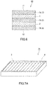
- An air filter medium 60 shown in FIG. 6 includes three air-permeable fiber layers 3 in addition to the first porous PTFE membrane 1 and the second porous PTFE membrane 2.
- the three air-permeable fiber layers 3 include a first air-permeable fiber layer 3a, a second air-permeable fiber layer 3b, and a third air-permeable fiber layer 3c.
- the air filter medium 60 has a multilayer structure composed of the first air-permeable fiber layer 3a, first porous PTFE membrane 1, third air-permeable fiber layer 3c, second porous PTFE membrane 2, and second air-permeable fiber layer 3b which are arranged in this order from the upstream side in the air flow direction.
- the first air-permeable fiber layer 3a forms the first main surface 11 of the air filter medium 60.
- the second air-permeable fiber layer 3b forms the second main surface 12 of the air filter medium 60.
- the first air-permeable fiber layer 3a is in contact with one surface of the first porous PTFE membrane 1, while the third air-permeable fiber layer 3c is in contact with the other surface of the first porous PTFE membrane 1.
- the second air-permeable fiber layer 3b is in contact with one surface of the second porous PTFE membrane 2, while the third air-permeable fiber layer 3c is in contact with the other surface of the second porous PTFE membrane 2.
- the first air-permeable fiber layer 3a When viewed from the first porous PTFE membrane 1, the first air-permeable fiber layer 3a is disposed on a side opposite to a side where the second porous PTFE membrane 2 is disposed. When viewed from the second porous PTFE membrane 2, the second air-permeable fiber layer 3b is disposed on a side opposite to a side where the first porous PTFE membrane 1 is disposed.
- the first porous PTFE membrane 1 and the second porous PTFE membrane 2 are arranged so that an air flow moving from the first main surface 11 to the second main surface 12 passes through the first porous PTFE membrane 1 and subsequently through the second porous PTFE membrane 2.
- the air filter medium according to the present invention is not limited to the configurations shown in FIGS. 1 to 6 and may further include an additional layer. Examples of the additional layer include a glass filter medium, a melt-blown non-woven fabric, and a nanofiber layer which may be disposed upstream of the first porous PTFE membrane 1.
- the first porous PTFE membrane 1 has moderate air permeability, and collects relatively large-diameter particles of oil mist in advance to prevent the second porous PTFE membrane 2 from being clogged with oil mist.
- the presence of the first porous PTFE membrane 1 reduces a pressure drop increase resulting from the use of the air filter media 10, 20, 30, 40, 50, and 60, thus increasing the service life of the air filter media 10, 20, 30, 40, 50, and 60.
- the contact angle of the first porous PTFE membrane 1 with water is in the range of 154° to 165°.
- permeation of oil into the first porous PTFE membrane 1 is reduced.
- the first porous PTFE membrane 1 collects relatively large-diameter particles of oil, and thus the second porous PTFE membrane 2 is prevented from being clogged with oil.
- Spreading of oil attached to the surface of the first porous PTFE membrane 1 is also reduced.
- a droplet of oil tends to maintain a spherical shape on the first porous PTFE membrane 1. That makes a droplet of oil less likely to block pores of the first porous PTFE membrane 1.
- the first porous PTFE membrane 1 can collect and retain more oil while an increase in pressure drop is reduced. That is, the amount of retained oil can be increased while pressure drop across the air filter medium is reduced.
- Equation (A) shows a relationship between the contact angle ⁇ and the water entry pressure of a porous membrane.
- the water entry pressure H on the left side represents the upper limit of the water height at which water cannot pass through the porous membrane.
- the water entry pressure increases with an increasing contact angle ⁇ (90° ⁇ ⁇ ⁇ 180°).
- H ⁇ 2 Tcos ⁇ / Sgr
- the contact angle can be measured with a commercially-available contact angle meter. Specifically, a syringe with a needle is held so that the tip of the needle does not have contact with a specimen (porous PTFE membrane). A 2 ⁇ L droplet (a droplet of distilled water) is forced out through the tip of the needle. With the droplet held at the tip of the needle, the syringe is moved downward to let the droplet have contact with the specimen. The syringe is moved upward to place the droplet alone on the specimen, and the contact angle of the droplet is measured. As shown in FIG. 9 , the contact angle is an angle ⁇ between a tangent of a droplet 14 and a surface 16 of a specimen. The contact angle can be measured according to the sessile drop method specified in Japanese Industrial Standards (JIS) R 3257 (1999). The average of contact angle values measured at five points of a specimen can be adopted as the contact angle of the specimen.
- JIS Japanese Industrial Standards
- the contact angle for example, a 2 pL droplet of water is used. It is difficult to measure the contact angle of the porous PTFE membrane with oil because a 2 pL droplet of oil dropped on the porous PTFE membrane permeates the porous PTFE membrane.
- the contact angle of the porous PTFE membrane with water is indeed different from the contact angle of the porous PTFE membrane with oil.
- the contact angle of the porous PTFE membrane with water and the contact angle of the porous PTFE membrane with oil show the same tendency. Therefore, it is sufficiently reasonable to adopt the contact angle of the porous PTFE membrane with water as a measure of the likelihood of capillary action of oil in the porous PTFE membrane. This is evident also from Examples described below.
- the air-permeable fiber layer 3 may be in contact with the surface of the first porous PTFE membrane 1.
- the air-permeable fiber layer 3 can be peeled from the first porous PTFE membrane 1 to measure the contact angle of the first porous PTFE membrane 1.
- the air-permeable fiber layer 3 is, for example, a non-woven fabric which has a coarse texture
- the surface of the first porous PTFE membrane 1 can be exposed through the interstices between the fibers of the non-woven fabric to measure the contact angle of the first porous PTFE membrane 1.
- the other properties of the first porous PTFE membrane 1 can also be measured by peeling the air-permeable fiber layer 3 from the first porous PTFE membrane 1.
- the average pore diameter of the first porous PTFE membrane 1 be larger than the average pore diameter of the second porous PTFE membrane 2, because in this case the effect on the resistance to clogging with oil mist is further enhanced.
- the average pore diameter of the first porous PTFE membrane 1 disposed on the upstream side in the air flow direction is larger than the average pore diameter of the second porous PTFE membrane 2
- the first porous PTFE membrane 1 collects relatively large particles of oil mist in advance on the upstream side in the air flow direction while the second porous PTFE membrane 2 collects smaller particles of oil mist on the downstream side in the air flow direction.
- both the first porous PTFE membrane 1 and second porous PTFE membrane 2 can collect oil mist, clogging of the air filter medium can be further reduced.
- the average pore diameter of the first porous PTFE membrane 1 is, for example, 3 to 30 pm, preferably 4 to 21 ⁇ m, and more preferably 4 to 10 ⁇ m.
- the average pore diameters of the first porous PTFE membrane 1 and the second porous PTFE membrane 2 described later can be determined by measuring the pore diameter of each porous PTFE membrane at three or more points with "Perm Porometer" manufactured by Porous Materials Inc. and calculating the average of the measured values.
- the thickness of the first porous PTFE membrane 1 be larger than the thickness of the second porous PTFE membrane 2, because in this case the effect on the resistance to clogging with oil mist is further enhanced.
- the first porous PTFE membrane 1 collects relatively large particles of oil mist in advance on the upstream side in the air flow direction while the second porous PTFE membrane 2 collects smaller particles of oil mist on the downstream side in the air flow direction.
- both the first porous PTFE membrane 1 and second porous PTFE membrane 2 can collect oil mist, clogging of the air filter medium can be further reduced.
- the thickness of the first porous PTFE membrane 1 is, for example, 7 to 36 ⁇ m and preferably 12 to 24 ⁇ m.
- the value of the thickness is an average of thickness values measured at any number of points (five points, for example) using a dial thickness gauge.
- the porosity of the first porous PTFE membrane 1 be higher than the porosity of the second porous PTFE membrane 2, because in this case the effect on the resistance to clogging with oil mist is further enhanced.
- the porosity of the first porous PTFE membrane 1 is higher than the porosity of the second porous PTFE membrane 2
- the first porous PTFE membrane 1 collects relatively large particles of oil mist in advance on the upstream side in the air flow direction while the second porous PTFE membrane 2 collects smaller particles of oil mist on the downstream side in the air flow direction.
- both the first porous PTFE membrane 1 and second porous PTFE membrane 2 can collect oil mist, clogging of the air filter medium can be further reduced.
- the porosity of the first porous PTFE membrane 1 is, for example, 90 to 99%.
- the pressure drop across the first porous PTFE membrane 1 is, for example, 10 to 45 Pa and preferably 15 to 40 Pa.
- the pressure drop across the first porous PTFE membrane 1, the pressure drop across the second porous PTFE membrane 2 described later, and the pressure drop across the air filter medium can be measured by the following method.
- the first porous PTFE membrane 1, second porous PTFE membrane 2, or air filter medium is set in a circular holder with an effective area of 100 cm 2 , and air is passed through the first porous PTFE membrane 1, second porous PTFE membrane 2, or air filter medium set in the holder.
- the linear flow velocity of the air passing through the first porous PTFE membrane 1, second porous PTFE membrane 2, or air filter medium is adjusted to 5.3 cm/sec with the aid of a flowmeter, and then the pressure drop is measured with a pressure meter (manometer). The pressure drop is measured eight times for the first porous PTFE membrane 1, second porous PTFE membrane 2, or air filter medium, and the average of the eight values is calculated.
- the PF value of the first porous PTFE membrane 1 is, for example, in the range of 6 to 8. When the PF value of the first porous PTFE membrane 1 is within this range, large particles of oil mist can be preferentially collected by the first porous PTFE membrane 1.
- the PF value is used as a measure for evaluation of how well balanced the pressure drop and collection efficiency are.
- the PF value is determined by the following equation (1). A higher PF value indicates higher performance of the porous PTFE membranes and air filter medium.
- PL represents pressure drop.
- the second term on the right side is determined by values obtained by measurement at a permeation rate of 5.3 cm/sec using poly- ⁇ -olefin (PAO) with a particle diameter of 0.10 to 0.20 ⁇ m.
- the PF value of the first porous PTFE membrane 1 can be measured by peeling the air-permeable fiber layer 3 and second porous PTFE membrane 2 from the first porous PTFE membrane 1. The same applies to measurement of the PF value of the second porous PTFE membrane 2.
- the second porous PTFE membrane 2 collects small particles of oil mist that cannot be collected by the first porous PTFE membrane 1, and thus increases the amount of oil mist collected by the air filter media 10, 20, 30, 40, 50, and 60.
- the contact angle of the first porous PTFE membrane 1 is different from the contact angle of the second porous PTFE membrane 2 due to differences in production conditions.
- the contact angle of the second porous PTFE membrane 2 with water is smaller than the contact angle of the first porous PTFE membrane 1 with water. Specifically, the contact angle of the second porous PTFE membrane 2 with water is less than 154°.
- the lower limit of the contact angle of the second porous PTFE membrane 2 is not particularly limited, and is, for example, 138°.
- the average pore diameter of the second porous PTFE membrane 2 is, for example, 0.1 to 3 ⁇ m, preferably 0.2 to 3 pm, and more preferably 0.6 to 1.5 ⁇ m.
- the thickness of the second porous PTFE membrane 2 is, for example, 1 ⁇ m or more and less than 7 ⁇ m and preferably 1 to 5 ⁇ m.
- the ratio of the thickness of the first porous PTFE membrane 1 to the thickness of the second porous PTFE membrane 2 is desirably more than 1.
- the porosity of the second porous PTFE membrane 2 is, for example, 50% or more and less than 90%.
- the pressure drop across the second porous PTFE membrane 2 is, for example, 50 to 300 Pa, preferably 60 to 140 Pa, and more preferably 80 to 120 Pa.
- the PF value of the second porous PTFE membrane 2 is, for example, in the range of 20 to 40. When the PF value of the second porous PTFE membrane 2 is within this range, fine dust and oil mist can be collected by the second porous PTFE membrane 2 and thus an air filter medium having a high collection efficiency can be obtained.
- a liquid lubricant is added and mixed with an unsintered PTFE fine powder.
- the PTFE fine powder used is not particularly limited and can be a commercially-available product.
- the liquid lubricant used is not particularly limited, as long as the liquid lubricant can wet the surface of the PTFE fine powder and can be removed later.
- Examples of liquid lubricants that can be used include: hydrocarbon oils such as naphtha, white oil, liquid paraffin, toluene, and xylene; alcohols; ketones; and esters. Two or more liquid lubricants may be used in combination.
- the proportion of the liquid lubricant added to the PTFE fine powder is chosen as appropriate depending, for example, on the type of the PTFE fine powder, the type of the lubricant oil, and the conditions of sheet forming described later.
- the amount of the liquid lubricant is 15 to 35 parts by weight with respect to 100 parts by weight of the PTFE fine powder.
- the mixture of the unsintered PTFE fine powder and the liquid lubricant is formed into a sheet shape without sintering, and thus a sheet-shaped body of PTFE is obtained.
- the method for sheet forming include: a rolling method in which the mixture is extruded into a rod shape and then the rod-shaped body is flattened with a pair of rolls; and an extrusion method in which the mixture is extruded into a plate shape to obtain a sheet-shaped body.
- the sheet-shaped body made by such a method is in the form of a strip. Two or more methods may be combined to accomplish the sheet forming.
- the thickness of the sheet-shaped body of PTFE is chosen as appropriate depending, for example, on the conditions of the subsequent stretching and is, for example, 0.1 to 0.5 mm.
- the liquid lubricant contained in the sheet-shaped body of PTFE is preferably removed by a method such as heating or extraction before the stretching step subsequently performed.
- the solvent used for extraction include, but are not particularly limited to, normal-decane, dodecane, naphtha, kerosene, and liquid paraffin.
- the stretching method is preferably biaxial stretching.
- the conditions such as the stretching temperature and stretching ratio need to be adjusted to achieve a desired contact angle for each membrane.
- the sheet-shaped body of PTFE is stretched while being heated at a temperature equal to or higher than the melting point of PTFE.
- the sheet-shaped body of PTFE is stretched in the longitudinal direction (machine direction (MD)), for example, at 370 to 380°C.
- MD machine direction
- the stretching ratio in the longitudinal direction can be set so that the length after stretching is, for example, 50 to 200 times, preferably 80 to 150 times, and more preferably 90 to 100 times the length before stretching.
- the sheet-shaped body of PTFE is stretched in the width direction (transverse direction (TD)), for example, at 130 to 400°C.
- the stretching ratio in the width direction can be set so that the width after stretching is 5 to 8 times the width before stretching.
- the stretching in the longitudinal direction at a temperature equal to or higher than the melting point (327°C) of PTFE tends to result in a larger contact angle than stretching at a temperature lower than the melting point of PTFE.
- the sheet-shaped body of PTFE is stretched while being heated at a temperature lower than the melting point of PTFE.
- the sheet-shaped body of PTFE is stretched in the longitudinal direction, for example, at 270 to 290°C.
- the stretching ratio in the longitudinal direction can be set so that the length after stretching is 15 to 40 times the length before stretching.
- the sheet-shaped body of PTFE is stretched in the width direction, for example, at 120 to 130°C.
- the stretching ratio in the width direction can be set so that the width after stretching is 15 to 40 times the width before stretching.
- the first porous PTFE membrane 1 and the second porous PTFE membrane 2 are produced by the above methods, and these membranes are bonded together directly or with the air-permeable fiber layer 3 interposed therebetween. If necessary, the first air-permeable fiber layer 3a is bonded to the first porous PTFE membrane 1, and the second air-permeable fiber layer 3b is bonded to the second porous PTFE membrane 2. In this way, the air filter media described with reference to FIGS. 1 to 6 are obtained.
- PTFE is generally in a sintered state, unsintered state, or intermediate state (hereinafter may be referred to as "half-sintered state") depending on the condition of crystal transformation.
- half-sintered state When PTFE is completely sintered, one endothermic peak is observed around 325°C in differential scanning calorimetry (DSC).
- DSC differential scanning calorimetry
- PTFE When PTFE is completely unsintered, one endothermic peak is observed typically around 336°C in DSC. Depending on thermal history, however, there may be two separate peaks around 325°C and 336°C even when PTFE is in the unsintered state.
- the air filter medium of the present embodiment may include the air-permeable fiber layer 3.
- a material having sufficient air permeability is used as the air-permeable fiber layer 3.
- a material constituted by fibers such as short fibers and filaments and having higher air permeability than the first porous PTFE membrane 1 and second porous PTFE membrane 2 can be used as the air-permeable fiber layer 3, and examples of such a material include non-woven fabrics, woven fabrics, meshes (reticulated sheets), and other porous materials. Among these, non-woven fabrics are preferred because they are superior in terms of strength, flexibility, and workability.
- the average fiber diameter of the fibers constituting the air-permeable fiber layer 3 is, for example, 10 to 30 ⁇ m and preferably 15 to 25 ⁇ m.
- the mass per unit area of the air-permeable fiber layer 3 is, for example, 15 to 300 g/m 2 and preferably 15 to 100 g/m 2 in view of the air permeability of the air filter media 20, 30, 40, 50, and 60 and the ease of handling of the air filter media 20, 30, 40, 50, and 60 in pleating.
- the thickness of the air-permeable fiber layer 3 is preferably 130 to 200 ⁇ m in view of the air permeability of the air filter media 20, 30, 40, 50, and 60, the ease of handling of the air filter media 20, 30, 40, 50, and 60 in pleating, and the overall thickness of the air filter media 20, 30, 40, 50, and 60.
- the air filter media 40, 50, and 60 described with reference to FIGS. 4 to 6 have the air-permeable fiber layer 3 (first air-permeable fiber layer 3a) disposed upstream of the first porous PTFE membrane 1.
- the mass per unit area of this air-permeable fiber layer 3 is large, oil mist is likely to be collected by the air-permeable fiber layer 3. Accordingly, the mass per unit area of the air-permeable fiber layer 3 disposed upstream of the first porous PTFE membrane 1 is, for example, 30 to 260 g/m 2 and preferably 30 to 200 g/m 2 .
- the mass per unit area of the air-permeable fiber layers 3 (second air-permeable fiber layer 3b and third air-permeable fiber layer 3c) disposed downstream of the first porous PTFE membrane 1 can be determined in view of reducing the increase in pressure drop.
- the mass per unit area of the air-permeable fiber layers 3 disposed downstream of the first porous PTFE membrane 1 is, for example, equal to or smaller than the mass per unit area of the air-permeable fiber layer 3 disposed upstream of the first porous PTFE membrane 1.
- the mass per unit area of the air-permeable fiber layers 3 disposed downstream of the first porous PTFE membrane 1 is, for example, 15 to 100 g/m 2 and preferably 15 to 30 g/m 2 . All of the air-permeable fiber layers 3 of the air filter medium 50 (or 60) may have the same structure and properties.
- Examples of the material of the fibers constituting the air-permeable fiber layer 3 include, but are not particularly limited to: polyolefins such as polyethylene (PE) and polypropylene (PP); polyesters such as polyethylene terephthalate (PET); polyamides; and composites thereof.
- the fibers constituting the air-permeable fiber layer 3 preferably contain a polyolefin with a low melting point, in particular polyethylene, in view of easy and reliable bonding between the first porous PTFE membrane 1 or second porous PTFE membrane 2 and the air-permeable fiber layer 3.
- the air-permeable fiber layer 3 is preferably constituted by composite fibers having a core-sheath structure in which the core component has a higher melting point than the sheath component.
- a material with a relatively high melting point such as PET
- a material with a relatively low melting point such as polyethylene
- the fibers having a core-sheath structure include: fibers having a core portion made of PET and a sheath portion made of PE (PET/PE fibers); and fibers having a core portion made of PP and a sheath portion made of PE (PP/PE fibers).
- the use of the air-permeable fiber layer 3 constituted by fibers having a core-sheath structure reduces heat-induced change in the structure and thickness of the air-permeable fiber layer 3 when the air-permeable fiber layer 3 is laminated to the first porous PTFE membrane 1 or second porous PTFE membrane 2 by heating. Additionally, the first porous PTFE membrane 1 and second porous PTFE membrane 2 can be prevented from being damaged due to shrinkage of the air-permeable fiber layer 3.
- the air-permeable fiber layer 3 is preferably constituted by PET/PE fibers.
- Examples of the method for joining the first porous PTFE membrane 1, second porous PTFE membrane 2, and air-permeable fiber layer 3 together include heat-assisted nip lamination and lamination using an infrared heater (see JP 2003-190749 A ). Of these, the lamination using an infrared heater is preferred because this lamination can achieve strong bonding without decreasing the thickness of each layer.
- the air-permeable fiber layer 3 is constituted by fibers having a core-sheath structure, it is preferable that the temperature of heating of the air-permeable fiber layer 3 be set equal to or higher than the softening point (preferably equal to or higher than the melting point) of the sheath component and lower than the melting point of the core component.
- the order of stacking of the first porous PTFE membrane 1, second porous PTFE membrane 2, and air-permeable fiber layer 3 is not limited, as long as the first porous PTFE membrane and the second porous PTFE membrane are arranged so that an air flow moving from the first main surface 11 to the second main surface 12 passes through the first porous PTFE membrane and subsequently through the second porous PTFE membrane.
- the air-permeable fiber layers 3 may be the same or different from each other.
- the pressure drop across the air filter medium is, for example, 60 to 350 Pa, preferably 80 to 270 Pa, and more preferably 100 to 200 Pa.
- the air filter medium of the present embodiment has excellent resistance to clogging with oil mist.
- PAO poly- ⁇ -olefin
- the amount of PAO collected by the air filter medium is, for example, 20 mg/m 2 /Pa or more, preferably 70 mg/m 2 /Pa or more, more preferably 90 mg/m 2 /Pa or more, and particularly preferably 100 mg/m 2 /Pa or more, at a time point where the pressure drop reaches 500 Pa.
- the upper limit of the amount of collected PAO is not particularly defined and is, for example, 200 mg/m 2 /Pa.
- the amount of collected PAO (mg/m 2 /Pa) is determined by dividing an increase in weight of the air filter medium (the weight of PAO) (mg) by the area (m 2 ) of the air filter medium and by further dividing the resulting value by an increase in pressure drop (500 - (pressure drop at the start of measurement)) (Pa).
- “Durasyn 164" manufactured by INEOS can be used as the PAO.
- the polydisperse PAO with an average particle diameter of 0.15 ⁇ m can be generated, for example, using a constant-output aerosol atomizer ("TSI No. 3076" manufactured by TOKYO DYLEC CORP.).
- the air filter medium of the present embodiment further has excellent resistance to clogging with dust.
- NaCl in the form of polydisperse particles with an average particle diameter of 0.5 ⁇ m is passed through the air filter medium at a concentration of 1 to 3 g/m 3 and a linear flow velocity of 5.3 cm/sec to measure the change in pressure drop
- the amount of NaCl collected by the air filter medium is, for example, 8 mg/m 2 /Pa or more, preferably 9 mg/m 2 /Pa or more, more preferably 12 mg/m 2 /Pa or more, and particularly preferably 17 mg/m 2 /Pa or more, at a time point where the pressure drop reaches 500 Pa.
- the upper limit of the amount of collected NaCl is not particularly defined and is, for example, 20 mg/m 2 /Pa.
- the amount of collected NaCl (mg/m 2 /Pa) is determined by dividing an increase in weight of the air filter medium (the weight of NaCl) (mg) by the area (m 2 ) of the air filter medium and by further dividing the resulting value by an increase in pressure drop (500 - (pressure drop at the start of measurement)) (Pa).
- the polydisperse NaCl with an average particle diameter of 0.5 ⁇ m can be generated, for example, using a constant-output aerosol atomizer ("TSI No. 3076" manufactured by TOKYO DYLEC CORP.).
- the collection efficiency of the air filter medium of the present embodiment is, for example, 98 to 99.999995%, preferably 99.5 to 99.99999%, and more preferably 99.95 to 99.99995%.
- the air filter medium of the present embodiment may be an air filter medium complying with HEPA grade (high-efficiency particulate air grade) specified in Japanese Industrial Standard (JIS) Z 8122 (2000) or may be an air filter medium complying with ULPA grade (ultra-low penetration air grade) specified in the same standard.
- the air filter medium of the present embodiment may be pleated by a known technique.
- the pleating is accomplished, for example, by using a reciprocating machine to fold the filter medium along mountain and valley folds arranged alternately in parallel on the surface of the filter medium and thereby form the medium into a series of W-shapes.
- the pleated air filter medium may be called an air filter pack.
- the air filter pack may be provided with a spacer to maintain the pleated shape.
- a string of resin, called a bead is often used as the spacer.
- the bead is disposed on the filter medium to extend in a direction perpendicular to the mountain (valley) folds (in such a direction as to traverse the mountains and valleys).
- a plurality of such beads are disposed on the filter medium to extend in this direction with predetermined intervals therebetween.
- the beads are disposed, for example, on both of the front and back sides of the filter medium.
- the beads are typically formed by melting a resin such as polyamide and polyolefin and applying the molten resin.
- the pleated air filter medium (air filter pack 4) is processed into an air filter unit 70 shown in FIG. 7A by supporting the peripheral portion of the air filter pack 4 with a frame (support frame).
- a frame support frame
- a member made of metal or resin may be used as a frame 5 surrounding the periphery of the air filter pack.
- the pleated air filter medium may be fixed to the frame simultaneously with formation of the frame by injection molding.
- a pleat distance P (distance between peaks of adjacent mountains) of the pleated air filter medium 4 is adjusted to a width which allows the air filter medium 4 to have a sufficient surface area.
- the pleat distance P is adjusted to the range of, for example, 2.54 to 12.7 mm and preferably 3.18 to 6.35 mm.
- a pleat height h of the air filter medium 4 is adjusted to the range of, for example, 5 to 300 mm and preferably 20 to 250 mm.
- the value of (pleat distance P)/(pleat height h) is, for example, 0.25 or less and preferably 0.22 or less.
- the frame 5 may be made of a metallic material such as aluminum, stainless steel, a plated steel sheet, and coated steel sheet, or may be made of a resin material such as polyolefin, polyamide (including aromatic polyamide), polyurethane, polyester, polystyrene (such as ABS), and polycarbonate.
- the frame 5 may alternatively be made of a wood material such as a fire-retardant plywood sheet and a plywood sheet.
- the air filter medium of the present embodiment has front and back sides distinguished from each other. If the second porous PTFE membrane 2 is disposed on the upstream side in the air flow direction while the first porous PTFE membrane 1 is disposed on the downstream side in the air flow direction, sufficient effect on the resistance to clogging with oil mist cannot be achieved.
- the front and back sides can be mistakenly switched, for example, when the air filter medium is subjected to a process such as rewinding in slitting (the process of adjusting the dimensions of the air filter medium by cutting) and pleating. To solve this problem, the configurations described hereinafter can be employed.
- the first air-permeable fiber layer 3a and the second air-permeable fiber layer 3b may be each an embossed non-woven fabric; in this case, for example, the embossing pattern of the first air-permeable fiber layer 3a is different from the embossing pattern of the second air-permeable fiber layer 3b.
- the first main surface 11 and the second main surface 12 can be distinguished to prevent the front and back sides from being mistakenly switched.
- embossed non-woven fabric refers to a non-woven fabric subjected to embossing.
- an embossed non-woven fabric is a non-woven fabric having one or more recessed portions and one or more projecting portions.
- the embossed non-woven fabric has higher stiffness and higher strength than an unembossed non-woven fabric as thick as the embossed non-woven fabric.
- the embossed non-woven fabric has an indented pattern or, in other words, the embossed non-woven fabric has a sea-island structure when viewed in plan.
- Examples of embossed non-woven fabrics having different embossing patterns include a T-type embossed non-woven fabric shown in FIG. 8A and an S-type embossed non-woven fabric shown in FIG. 8B .
- T-type embossed non-woven fabric as shown in FIG. 8A , elliptical portions corresponding to "islands" (where the fibers are not melted) are projecting portions, and a portion corresponding to the sea (where the fibers are melted) is a recessed portion.
- the T-type embossed non-woven fabric typically has a single, continuous recessed portion and a plurality of projecting portions.
- the T-type embossed non-woven fabric may have a plurality of recessed portions separate from each other.
- the S-type embossed non-woven fabric As shown in FIG. 8B , circular portions corresponding to "islands" (where the fibers are melted) are recessed portions, and a portion corresponding to the "sea” (where the fibers are not melted) is a projecting portion.
- the S-type embossed non-woven fabric typically has a plurality of recessed portions and a single, continuous projecting portion.
- the S-type embossed non-woven fabric may have a plurality of projecting portions separate from each other. With the use of these embossed non-woven fabrics, it is easier to achieve high air permeability and high bond strength.
- the first main surface 11 and the second main surface 12 can be distinguished when the embossed area ratio in the embossed non-woven fabric used as the first air-permeable fiber layer 3a is sufficiently different from the embossed area ratio in the embossed non-woven fabric used as the second air-permeable fiber layer 3b.
- embossed area ratio as used to describe an embossed non-woven fabric refers to the ratio of the area of a recessed portion (portion where fibers are melted) or the total area of a plurality of recessed portions to the area of the embossed non-woven fabric.
- the embossed area ratio can be calculated by the following method.
- the surface of the non-woven fabric is observed with a microscope such as an electron microscope at a given magnification (for example, a magnification of 25 times).
- a microscope such as an electron microscope at a given magnification (for example, a magnification of 25 times).
- the proportion of the embossed portion(s) is calculated.
- the recessed portions are assumed to be circular.
- the projecting portions are assumed to be elliptical.
- the calculation of the embossed area ratio should be carried out using an image of an adequate size.
- Embossed non-woven fabrics include a double-embossed non-woven fabric having two embossed surfaces and a single-embossed non-woven fabric having only one embossed surface.
- a double-embossed non-woven fabric may be used as one of the first air-permeable fiber layer 3a and the second air-permeable fiber layer 3b while a single-embossed non-woven fabric is used as the other.
- An embossed non-woven fabric may be used as one of the first air-permeable fiber layer 3a and the second air-permeable fiber layer 3b while an unembossed non-woven fabric is used as the other.
- At least one selected from the first main surface 11 and the second main surface 12 is provided with an identification mark that allows distinguishing between the first main surface 11 and the second main surface 12. This configuration is advantageous because it is applicable to all of the air filter media described with reference to FIGS. 1 to 6 .
- the type of the identification mark that allows distinguishing between the first main surface 11 and the second main surface 12 is not particularly limited.
- the identification mark includes at least one selected from the group consisting of a letter, a figure, and a symbol.
- Examples of the method for providing the identification mark include: applying an ink to at least one selected from the first main surface 11 and the second main surface 12; and forming asperities on at least one selected from the first main surface 11 and the second main surface 12. These methods make it possible to distinguish between the first main surface 11 and the second main surface 12.
- the asperities can be formed, for example, by pressing a portion of the air filter medium, by melting a portion of the air filter medium, or by punching a portion of the member (for example, the first air-permeable fiber layer 3a) forming the first main surface 11 or second main surface 12.
- An embossing technique can be employed for the formation of asperities by pressing or melting.
- the melting can be accomplished using a commercially-available laser marker.
- At least one selected from the first air-permeable fiber layer 3a and the second air-permeable fiber layer 3b is colored, and the color of the first air-permeable fiber layer 3a is different from the color of the second air-permeable fiber layer 3b.
- a colored non-woven fabric is used as one of the first air-permeable fiber layer 3a and the second air-permeable fiber layer 3b.
- the colored non-woven fabric can be a non-woven fabric containing a colorant such as a pigment.
- the non-woven fabric may be colored with a chromatic color.
- one of the first air-permeable fiber layer 3a and the second air-permeable fiber layer 3b is constituted by a non-woven fabric colored with a chromatic color while the other is constituted by an uncolored (white) non-woven fabric.
- Such a configuration also allows distinguishing between the first main surface 11 and the second main surface 12.
- a PTFE fine powder (“CD129E", manufactured by Asahi Glass Co., Ltd.; standard specific gravity: 2.16) in an amount of 100 parts by weight was uniformly mixed with 20 parts by weight of a liquid lubricant (dodecane), and the resulting mixture was preformed.
- the preform was formed into a rod shape by paste extrusion, and the rod-shaped body was passed between a pair of metal pressure rolls to obtain a long sheet with a thickness of 200 ⁇ m.
- the long sheet was stretched in the longitudinal direction at a stretching temperature (furnace temperature) of 375°C in two stages; the sheet was stretched by a factor of 5 in the first stage and by a factor of 20 in the second stage.
- the sheet was then stretched by a factor of 7 in the width direction at a stretching temperature (furnace temperature of a tenter) of 320°C to prepare a first porous PTFE membrane A.
- the pressure drop across the first porous PTFE membrane A was 15 Pa.
- a PTFE fine powder (“CD129E", manufactured by Asahi Glass Co., Ltd.) in an amount of 100 parts by weight was uniformly mixed with 20 parts by weight of a liquid lubricant (dodecane), and the resulting mixture was preformed.
- the preform was formed into a rod shape by paste extrusion, and the rod-shaped body was passed between a pair of metal pressure rolls to obtain a long sheet with a thickness of 200 ⁇ m.
- the long sheet was stretched in the longitudinal direction at a stretching temperature of 375°C in two stages; the sheet was stretched by a factor of 5 in the first stage and by a factor of 20 in the second stage.
- the sheet was then stretched by a factor of 7 in the width direction at a stretching temperature of 300°C to prepare a first porous PTFE membrane A1.
- the pressure drop across the first porous PTFE membrane A1 was 20 Pa.
- a PTFE fine powder (“CD129E", manufactured by Asahi Glass Co., Ltd.) in an amount of 100 parts by weight was uniformly mixed with 20 parts by weight of a liquid lubricant (dodecane), and the resulting mixture was preformed.
- the preform was formed into a rod shape by paste extrusion, and the rod-shaped body was passed between a pair of metal pressure rolls to obtain a long sheet with a thickness of 200 ⁇ m.
- the long sheet was stretched in the longitudinal direction at a stretching temperature of 375°C in two stages; the sheet was stretched by a factor of 4.5 in the first stage and by a factor of 20 in the second stage.
- the sheet was then stretched by a factor of 6 in the width direction at a stretching temperature of 150°C to prepare a first porous PTFE membrane A2.
- the pressure drop across the first porous PTFE membrane A2 was 40 Pa.
- a PTFE fine powder (“CD129E", manufactured by Asahi Glass Co., Ltd.) in an amount of 100 parts by weight was uniformly mixed with 20 parts by weight of a liquid lubricant (dodecane), and the resulting mixture was preformed.
- the preform was formed into a rod shape by paste extrusion, and the rod-shaped body was passed between a pair of metal pressure rolls to obtain a long sheet with a thickness of 200 ⁇ m.
- the long sheet was stretched in the longitudinal direction in two stages; the sheet was stretched by a factor of 4 at a stretching temperature of 150°C in the first stage and by a factor of 2 at a stretching temperature of 375°C in the second stage.
- the sheet was then stretched by a factor of 8 in the width direction at a stretching temperature of 200°C to prepare a first porous PTFE membrane A3.
- the pressure drop across the first porous PTFE membrane A3 was 2500 Pa.
- a PTFE fine powder (“Fluon (registered trademark) PTFE CD-123", manufactured by Asahi Glass Co., Ltd.) in an amount of 100 parts by weight was uniformly mixed with 19 wt% of a liquid lubricant (naphtha), and the mixture was preformed under a condition of 20 kg/cm 2 .
- the resulting preform was then formed into a rod shape by paste extrusion, and the rod-shaped body was passed between a pair of metal pressure rolls to obtain a long sheet with a thickness of 200 ⁇ m.
- This sheet was stretched by a factor of 14 in the longitudinal direction of the sheet at a stretching temperature of 290°C, and the sheet was then stretched by a factor of 30 in the width direction of the sheet at a stretching temperature of 80°C using a tenter method.
- An unsintered porous PTFE membrane was thus obtained.
- This unsintered porous PTFE membrane was heat-treated at 400°C for 10 seconds with its dimensions fixed.
- a sintered first porous PTFE membrane B was thus obtained.
- the pressure drop across the first porous PTFE membrane B was 110 Pa.
- a PTFE fine powder (“Fluon (registered trademark) PTFE CD-123", manufactured by Asahi Glass Co., Ltd.) in an amount of 100 parts by weight was uniformly mixed with 19 wt% of a liquid lubricant (naphtha), and the mixture was preformed under a condition of 20 kg/cm 2 .
- the resulting preform was then formed into a rod shape by paste extrusion, and the rod-shaped body was passed between a pair of metal pressure rolls to obtain a long sheet with a thickness of 200 ⁇ m.
- This sheet was stretched by a factor of 15 in the longitudinal direction of the sheet at a stretching temperature of 290°C, and the sheet was then stretched by a factor of 30 in the width direction of the sheet at a stretching temperature of 80°C using a tenter method.
- An unsintered porous PTFE membrane was thus obtained.
- This unsintered porous PTFE membrane was heat-treated at 400°C for 10 seconds with its dimensions fixed.
- a sintered first porous PTFE membrane C was thus obtained.
- the pressure drop across the first porous PTFE membrane C was 100 Pa.
- a PTFE fine powder (“POLYFLON (registered trademark) PTFE F-104", manufactured by Daikin Industries, Ltd.) in an amount of 100 parts by weight was uniformly mixed with 19 wt% of a liquid lubricant (naphtha), and the mixture was preformed under a condition of 20 kg/cm 2 .
- the resulting preform was then formed into a rod shape by paste extrusion, and the rod-shaped body was passed between a pair of metal pressure rolls to obtain a long sheet with a thickness of 200 ⁇ m.
- This sheet was stretched by a factor of 35 in the longitudinal direction of the sheet at a stretching temperature of 280°C, and the sheet was then stretched by a factor of 35 in the width direction of the sheet at a stretching temperature of 120°C using a tenter method.
- An unsintered porous PTFE membrane was thus obtained.
- This unsintered porous PTFE membrane was heat-treated at 400°C for 10 seconds with its dimensions fixed.
- a sintered second porous PTFE membrane D was thus obtained.
- the pressure drop across the second porous PTFE membrane D was 80 Pa.
- a PTFE fine powder (“POLYFLON (registered trademark) PTFE F-104", manufactured by Daikin Industries, Ltd.) in an amount of 100 parts by weight was uniformly mixed with 20 parts by weight of a liquid lubricant (dodecane), and the resulting mixture was preformed.
- the preform was formed into a rod shape by paste extrusion, and the rod-shaped body was passed between a pair of metal pressure rolls to obtain a long sheet with a thickness of 200 ⁇ m.
- the long sheet was stretched by a factor of 18 in the longitudinal direction at a stretching temperature of 280°C and stretched by a factor of 35 in the width direction at a stretching temperature of 120°C to prepare a second porous PTFE membrane E.
- the pressure drop across the second porous PTFE membrane E was 140 Pa.
- a PTFE fine powder (“POLYFLON (registered trademark) PTFE F-104", manufactured by Daikin Industries, Ltd.) in an amount of 100 parts by weight was uniformly mixed with 20 parts by weight of a liquid lubricant (dodecane), and the resulting mixture was preformed.
- the preform was formed into a rod shape by paste extrusion, and the rod-shaped body was passed between a pair of metal pressure rolls to obtain a long sheet with a thickness of 500 ⁇ m.
- the long sheet was stretched by a factor of 23 in the longitudinal direction at a stretching temperature of 280°C and stretched by a factor of 35 in the width direction at a stretching temperature of 120°C to prepare a second porous PTFE membrane F.
- the pressure drop across the second porous PTFE membrane F was 220 Pa.
- the first porous PTFE membrane B was used as a second porous PTFE membrane G.
- a PTFE fine powder (“POLYFLON (registered trademark) PTFE F-104", manufactured by Daikin Industries, Ltd.) in an amount of 100 parts by weight was uniformly mixed with 19 wt% of a liquid lubricant (naphtha). The resulting mixture was preformed under a condition of 20 kg/cm 2 , and the resulting preform was then formed into a rod shape by paste extrusion. The rod-shaped body was passed between a pair of metal pressure rolls to obtain a long sheet with a thickness of 200 ⁇ m.
- This sheet was stretched by a factor of 37 in the longitudinal direction of the sheet at a stretching temperature of 280°C, and the sheet was then stretched by a factor of 35 in the width direction of the sheet at a stretching temperature of 140°C using a tenter method.
- An unsintered porous PTFE membrane was thus obtained.
- This unsintered porous PTFE membrane was heat-treated at 400°C for 10 seconds with its dimensions fixed.
- a sintered second porous PTFE membrane I was thus obtained.
- the pressure drop across the second porous PTFE membrane I was 60 Pa.
- a non-woven fabric manufactured by UNITIKA LTD., "ELEVES S0303WDO" core-sheath structure (core component: PET, sheath component: PE), mass per unit area: 30 g/m 2 , apparent density: 0.136 g/cm 3 , embossed area ratio: 15%, thickness: 0.22 mm), was used as an air-permeable fiber layer.
- the contact angle was measured by the method previously described.
- a commercially-available contact angle meter OCA 30, manufactured by DataPhysics Instruments GmbH
- OCA 30 OCA 30, manufactured by DataPhysics Instruments GmbH
- the pressure drop and collection efficiency were measured in advance by the following methods and the PF value was determined by the equations (1) and (2) previously described. The results are shown in Table 1.
- the first porous PTFE membranes, the second porous PTFE membranes, and the above air-permeable fiber layer were combined as shown in Table 1.
- the first air-permeable fiber layer, the first porous PTFE membrane, the third air-permeable fiber layer, the second porous PTFE membrane, and the second air-permeable fiber layer were stacked in this order, and they were thermally laminated by passing the stack between a pair of rolls heated to 80°C. In this way, air filter media having a multilayer structure as shown in FIG. 6 were produced.
- Each air filter medium was set in a circular holder with an effective area of 100 cm 2 . Air was passed through the air filter medium set in the holder, the linear flow velocity of the air passing through the air filter medium was adjusted to 5.3 cm/sec with the aid of a flowmeter, and then the pressure drop was measured with a pressure meter (manometer). For each air filter medium, the pressure drop was measured eight times, and the average of the eight values was calculated.
- Each air filter medium was set in the same device as in the pressure drop measurement.
- PAO in the form of polydisperse particles with an average particle diameter of 0.15 ⁇ m (“Durasyn 164" manufactured by INEOS) was passed through the air filter medium at a concentration of 20 to 40 g/m 3 and a linear flow velocity of 5.3 cm/sec using a constant-output aerosol atomizer ("TSI No. 3076" manufactured by TOKYO DYLEC CORP.), and the change in pressure drop was measured with a pressure meter (manometer).
- the weight (mg) of the air filter medium was measured at a time point where the pressure drop reached 500 Pa.
- Each air filter medium was set in the same device as in the pressure drop measurement.
- NaCl in the form of polydisperse particles with an average particle diameter of 0.5 ⁇ m was passed through the air filter medium at a concentration of 1 to 3 g/m 3 and a linear flow velocity of 5.3 cm/sec using a constant-output aerosol atomizer ("TSI No. 3076" manufactured by TOKYO DYLEC CORP.), and the change in pressure drop was measured with a pressure meter (manometer).
- the weight (mg) of the air filter medium was measured at a time point where the pressure drop reached 500 Pa.
- Each air filter medium was set in the same device as in the pressure drop measurement, and the linear flow velocity of gas passing through the air filter medium was adjusted to 5.3 cm/sec.
- Air containing poly- ⁇ -olefin (PAO) particles with a particle diameter of 0.1 to 0.2 ⁇ m at a concentration of about 1 ⁇ 10 9 particles/L was passed through the air filter medium.
- the concentration of the PAO particles present downstream of the air filter medium was measured with a particle counter, and the collection efficiency (%) was determined by the following equation.
- the PF values of the first porous PTFE membranes A, A1, and A2 were low.
- the contact angles of the first porous PTFE membranes A, A1, and A2 were, however, larger than the contact angles of the first porous PTFE membranes A3, B, and C.
- the contact angles of the second porous PTFE membranes were in the range of 148° to 153°.
- the contact angles of the second porous PTFE membranes D, E, F, and I were 153°, 151°, 148°, and 153°, respectively.
- the air filter media of Examples 1 to 4 yielded a smaller increase in pressure drop with collection of oil mist and were less clogged with oil mist than the air filter media of Comparative Examples 1 and 2.
- the amount of collected PAO and the amount of collected NaCl were unable to be measured for the air filter medium of Comparative Example 3 because the pressure drop was too large.
- the air filter medium of the present invention can be employed for various applications such as use as an intake air filter medium for turbines, use as a filter medium for outdoor air conditioners, use as an air filter medium for clean rooms intended for medical treatment or pharmaceutical operation, use as a filter medium for masks, and use as a filter medium for general home electric appliances.
- the air filter medium of the present invention is particularly suitable for use as an air filter medium to be subjected to a process such as pleating.
Landscapes
- Chemical & Material Sciences (AREA)
- Chemical Kinetics & Catalysis (AREA)
- Engineering & Computer Science (AREA)
- Textile Engineering (AREA)
- Separation Using Semi-Permeable Membranes (AREA)
- Filtering Materials (AREA)
- Filtering Of Dispersed Particles In Gases (AREA)
- Laminated Bodies (AREA)
- Respiratory Apparatuses And Protective Means (AREA)
Claims (7)
- Couche de filtre à air comprenant une première membrane de PTFE poreuse et une seconde membrane de PTFE poreuse, dans laquelle
la couche de filtre à air a une première surface principale et une seconde surface principale,
la première membrane de PTFE poreuse et la seconde membrane de PTFE poreuse sont agencées de sorte qu'un écoulement d'air se déplaçant de la première surface principale à la seconde surface principale passe à travers la première membrane de PTFE poreuse et ensuite à travers la seconde membrane de PTFE poreuse, et
un angle de contact de la première membrane de PTFE poreuse avec de l'eau est dans la plage de 154° à 165°. - Couche de filtre à air selon la revendication 1, dans laquelle un angle de contact de la seconde membrane de PTFE poreuse avec de l'eau est inférieur à l'angle de contact de la première membrane de PTFE poreuse.
- Couche de filtre à air selon la revendication 1 ou 2, dans laquelle un angle de contact de la seconde membrane de PTFE poreuse avec de l'eau est inférieur à 154°.
- Couche de filtre à air selon l'une quelconque des revendications 1 à 3, dans laquelle lorsqu'une poly-α-oléfine sous la forme de particules polydispersées avec un diamètre particulaire moyen de 0,15 µm est passée à travers la couche de filtre à air à une concentration de 20 à 40 g/m3 et une vitesse d'écoulement linéaire de 5,3 cm/s pour mesurer un changement de chute de pression, une quantité de poly-α-oléfine recueillie par la couche de filtre à air est de 20 mg/m2/Pa ou plus à un point dans le temps où la chute de pression atteint 500 Pa.
- Couche de filtre à air selon l'une quelconque des revendications 1 à 4, dans laquelle lorsque du NaCl sous la forme de particules polydispersées avec un diamètre particulaire moyen de 0,5 µm est passé à travers la couche de filtre à air à une concentration de 1 à 3 g/m3 et une vitesse d'écoulement linéaire de 5,3 cm/s pour mesurer un changement de chute de pression, une quantité de NaCl recueillie par la couche de filtre à air est de 8 mg/m2/Pa ou plus à un point dans le temps où la chute de pression atteint 500 Pa.
- Kit de filtre à air comprenant la couche de filtre à air selon l'une quelconque des revendications 1 à 5, la couche de filtre à air étant plissée.
- Module de filtre à air comprenant le kit de filtre à air selon la revendication 6 et un cadre supportant le kit de filtre à air.
Applications Claiming Priority (2)
| Application Number | Priority Date | Filing Date | Title |
|---|---|---|---|
| JP2016194411A JP6744188B2 (ja) | 2016-09-30 | 2016-09-30 | エアフィルタ濾材、エアフィルタパック及びエアフィルタユニット |
| PCT/JP2017/034581 WO2018062111A1 (fr) | 2016-09-30 | 2017-09-25 | Matériau de filtre à air, bloc de filtre à air et unité de filtre à air |
Publications (3)
| Publication Number | Publication Date |
|---|---|
| EP3520873A1 EP3520873A1 (fr) | 2019-08-07 |
| EP3520873A4 EP3520873A4 (fr) | 2020-03-04 |
| EP3520873B1 true EP3520873B1 (fr) | 2021-03-24 |
Family
ID=61760739
Family Applications (1)
| Application Number | Title | Priority Date | Filing Date |
|---|---|---|---|
| EP17856062.9A Active EP3520873B1 (fr) | 2016-09-30 | 2017-09-25 | Matériau de filtre à air, bloc de filtre à air et unité de filtre à air |
Country Status (8)
| Country | Link |
|---|---|
| US (1) | US11406927B2 (fr) |
| EP (1) | EP3520873B1 (fr) |
| JP (1) | JP6744188B2 (fr) |
| KR (1) | KR102628700B1 (fr) |
| CN (1) | CN109789353A (fr) |
| MY (1) | MY194795A (fr) |
| TW (1) | TWI783949B (fr) |
| WO (1) | WO2018062111A1 (fr) |
Families Citing this family (9)
| Publication number | Priority date | Publication date | Assignee | Title |
|---|---|---|---|---|
| JP6673230B2 (ja) | 2017-01-12 | 2020-03-25 | ダイキン工業株式会社 | エアフィルタ濾材 |
| DE102018003481A1 (de) * | 2018-04-27 | 2019-10-31 | Sartorius Stedim Biotech Gmbh | Flächengebilde und Filterelement mit hydrophober Trennlage, Verfahren zu ihrer Herstellung und ihre Verwendung |
| JP6816746B2 (ja) * | 2018-07-20 | 2021-01-20 | ダイキン工業株式会社 | エアフィルタ濾材、フィルタパック、およびエアフィルタユニット |
| USD910158S1 (en) * | 2019-02-20 | 2021-02-09 | Lg Electronics Inc. | Filter for air purifier |
| WO2020204177A1 (fr) * | 2019-04-04 | 2020-10-08 | 日東電工株式会社 | Matériau de filtration et unité de filtre |
| KR20210007134A (ko) | 2019-07-10 | 2021-01-20 | 주식회사 사이파이커피 | 커피 연속 추출장치 |
| JP2021046618A (ja) * | 2019-09-17 | 2021-03-25 | ユニチカ株式会社 | ポリテトラフルオロエチレン製の多孔質膜を支持するための支持体 |
| USD898177S1 (en) * | 2019-11-29 | 2020-10-06 | Shenzhen Shenyuanxin Technology Co., Ltd. | Air filter |
| TW202206522A (zh) | 2020-07-03 | 2022-02-16 | 日商日東電工股份有限公司 | 聚四氟乙烯多孔質膜、通氣膜及通氣構件 |
Family Cites Families (15)
| Publication number | Priority date | Publication date | Assignee | Title |
|---|---|---|---|---|
| JPH1180397A (ja) | 1997-07-16 | 1999-03-26 | Nitto Denko Corp | ポリテトラフルオロエチレン多孔質膜およびその製造方法 |
| JP2000079332A (ja) * | 1998-07-08 | 2000-03-21 | Nitto Denko Corp | エアフィルタ用ろ材 |
| JP2000300921A (ja) | 1999-04-21 | 2000-10-31 | Nitto Denko Corp | エアフィルタ濾材およびそれを用いたエアフィルタユニット |
| JP2001170424A (ja) | 1999-12-20 | 2001-06-26 | Nitto Denko Corp | エアフィルタ用ろ材およびそれを用いたエアフィルタユニット |
| JP3672868B2 (ja) | 2001-12-26 | 2005-07-20 | 日東電工株式会社 | ポリテトラフルオロエチレン多孔質膜複合材の製造方法 |
| JP3795027B2 (ja) * | 2003-04-02 | 2006-07-12 | 宇明泰化工股▲ふん▼有限公司 | フィルター用非対称性多孔質ポリテトラフルオロエチレン膜 |
| KR20100101606A (ko) * | 2007-12-06 | 2010-09-17 | 닛토덴코 가부시키가이샤 | 에어 필터 |
| CN102274695A (zh) * | 2010-06-08 | 2011-12-14 | 天津工业大学 | 一种分离膜制备方法 |
| US9751052B2 (en) * | 2011-11-17 | 2017-09-05 | Ngee Ann Polytechnic | Triple layer hydrophobic-hydrophilic membrane for membrane distillation applications |
| JP5947655B2 (ja) * | 2012-08-02 | 2016-07-06 | 日東電工株式会社 | ポリテトラフルオロエチレン多孔質膜、並びに、それを用いた通気膜および通気部材 |
| US20140275692A1 (en) * | 2013-03-15 | 2014-09-18 | Shagufta Patel | Modified surface energy non-woven filter element |
| JP5835389B2 (ja) * | 2014-03-26 | 2015-12-24 | ダイキン工業株式会社 | エアフィルタ用濾材、フィルタパック、エアフィルタユニット、およびエアフィルタ用濾材の製造方法 |
| EP3209027B1 (fr) * | 2014-10-16 | 2019-07-03 | Nitto Denko Corporation | Membrane laissant passer le son, son élément de membrane laissant passer le son, microphone et dispositif électronique |
| US20160361674A1 (en) * | 2014-12-15 | 2016-12-15 | Hollingsworth & Vose Company | Filter media including fine staple fibers |
| US20160166953A1 (en) * | 2014-12-15 | 2016-06-16 | Hollingsworth & Vose Company | Filter media including fine staple fibers |
-
2016
- 2016-09-30 JP JP2016194411A patent/JP6744188B2/ja active Active
-
2017
- 2017-09-25 EP EP17856062.9A patent/EP3520873B1/fr active Active
- 2017-09-25 KR KR1020197008642A patent/KR102628700B1/ko active IP Right Grant
- 2017-09-25 CN CN201780060348.1A patent/CN109789353A/zh active Pending
- 2017-09-25 WO PCT/JP2017/034581 patent/WO2018062111A1/fr unknown
- 2017-09-25 US US16/338,252 patent/US11406927B2/en active Active
- 2017-09-25 MY MYPI2019001703A patent/MY194795A/en unknown
- 2017-09-29 TW TW106133494A patent/TWI783949B/zh active
Also Published As
| Publication number | Publication date |
|---|---|
| EP3520873A4 (fr) | 2020-03-04 |
| KR102628700B1 (ko) | 2024-01-25 |
| US11406927B2 (en) | 2022-08-09 |
| US20190232211A1 (en) | 2019-08-01 |
| MY194795A (en) | 2022-12-15 |
| JP2018051544A (ja) | 2018-04-05 |
| CN109789353A (zh) | 2019-05-21 |
| TW201813704A (zh) | 2018-04-16 |
| KR20190054079A (ko) | 2019-05-21 |
| EP3520873A1 (fr) | 2019-08-07 |
| JP6744188B2 (ja) | 2020-08-19 |
| TWI783949B (zh) | 2022-11-21 |
| WO2018062111A1 (fr) | 2018-04-05 |
Similar Documents
| Publication | Publication Date | Title |
|---|---|---|
| EP3520873B1 (fr) | Matériau de filtre à air, bloc de filtre à air et unité de filtre à air | |
| EP3357564B1 (fr) | Milieu de filtre à air, bloc de filtre à air et unité de filtre à air | |
| EP3520874B1 (fr) | Matériau de filtre à air, bloc de filtre à air et unité de filtre à air | |
| EP3520875B1 (fr) | Matériau de filtre à air, bloc de filtre à air, unité de filtre à air | |
| EP3804832A1 (fr) | Milieu filtrant et unité filtrante comprenant celui-ci | |
| EP3903903A1 (fr) | Paquet de plis de filtre et unité de filtre à air |
Legal Events
| Date | Code | Title | Description |
|---|---|---|---|
| STAA | Information on the status of an ep patent application or granted ep patent |
Free format text: STATUS: THE INTERNATIONAL PUBLICATION HAS BEEN MADE |
|
| PUAI | Public reference made under article 153(3) epc to a published international application that has entered the european phase |
Free format text: ORIGINAL CODE: 0009012 |
|
| STAA | Information on the status of an ep patent application or granted ep patent |
Free format text: STATUS: REQUEST FOR EXAMINATION WAS MADE |
|
| 17P | Request for examination filed |
Effective date: 20190404 |
|
| AK | Designated contracting states |
Kind code of ref document: A1 Designated state(s): AL AT BE BG CH CY CZ DE DK EE ES FI FR GB GR HR HU IE IS IT LI LT LU LV MC MK MT NL NO PL PT RO RS SE SI SK SM TR |
|
| AX | Request for extension of the european patent |
Extension state: BA ME |
|
| DAV | Request for validation of the european patent (deleted) | ||
| DAX | Request for extension of the european patent (deleted) | ||
| A4 | Supplementary search report drawn up and despatched |
Effective date: 20200204 |
|
| RIC1 | Information provided on ipc code assigned before grant |
Ipc: B01D 46/52 20060101ALI20200129BHEP Ipc: B32B 27/30 20060101ALI20200129BHEP Ipc: B01D 71/36 20060101ALI20200129BHEP Ipc: B01D 39/16 20060101AFI20200129BHEP Ipc: B01D 63/14 20060101ALI20200129BHEP Ipc: B32B 3/28 20060101ALI20200129BHEP |
|
| GRAP | Despatch of communication of intention to grant a patent |
Free format text: ORIGINAL CODE: EPIDOSNIGR1 |
|
| STAA | Information on the status of an ep patent application or granted ep patent |
Free format text: STATUS: GRANT OF PATENT IS INTENDED |
|
| INTG | Intention to grant announced |
Effective date: 20201201 |
|
| GRAS | Grant fee paid |
Free format text: ORIGINAL CODE: EPIDOSNIGR3 |
|
| GRAA | (expected) grant |
Free format text: ORIGINAL CODE: 0009210 |
|
| STAA | Information on the status of an ep patent application or granted ep patent |
Free format text: STATUS: THE PATENT HAS BEEN GRANTED |
|
| AK | Designated contracting states |
Kind code of ref document: B1 Designated state(s): AL AT BE BG CH CY CZ DE DK EE ES FI FR GB GR HR HU IE IS IT LI LT LU LV MC MK MT NL NO PL PT RO RS SE SI SK SM TR |
|
| REG | Reference to a national code |
Ref country code: GB Ref legal event code: FG4D |
|
| REG | Reference to a national code |
Ref country code: CH Ref legal event code: EP |
|
| REG | Reference to a national code |
Ref country code: DE Ref legal event code: R096 Ref document number: 602017035432 Country of ref document: DE |
|
| REG | Reference to a national code |
Ref country code: IE Ref legal event code: FG4D |
|
| REG | Reference to a national code |
Ref country code: AT Ref legal event code: REF Ref document number: 1373914 Country of ref document: AT Kind code of ref document: T Effective date: 20210415 |
|
| REG | Reference to a national code |
Ref country code: LT Ref legal event code: MG9D |
|
| PG25 | Lapsed in a contracting state [announced via postgrant information from national office to epo] |
Ref country code: GR Free format text: LAPSE BECAUSE OF FAILURE TO SUBMIT A TRANSLATION OF THE DESCRIPTION OR TO PAY THE FEE WITHIN THE PRESCRIBED TIME-LIMIT Effective date: 20210625 Ref country code: FI Free format text: LAPSE BECAUSE OF FAILURE TO SUBMIT A TRANSLATION OF THE DESCRIPTION OR TO PAY THE FEE WITHIN THE PRESCRIBED TIME-LIMIT Effective date: 20210324 Ref country code: HR Free format text: LAPSE BECAUSE OF FAILURE TO SUBMIT A TRANSLATION OF THE DESCRIPTION OR TO PAY THE FEE WITHIN THE PRESCRIBED TIME-LIMIT Effective date: 20210324 Ref country code: NO Free format text: LAPSE BECAUSE OF FAILURE TO SUBMIT A TRANSLATION OF THE DESCRIPTION OR TO PAY THE FEE WITHIN THE PRESCRIBED TIME-LIMIT Effective date: 20210624 Ref country code: BG Free format text: LAPSE BECAUSE OF FAILURE TO SUBMIT A TRANSLATION OF THE DESCRIPTION OR TO PAY THE FEE WITHIN THE PRESCRIBED TIME-LIMIT Effective date: 20210624 |
|
| PG25 | Lapsed in a contracting state [announced via postgrant information from national office to epo] |
Ref country code: RS Free format text: LAPSE BECAUSE OF FAILURE TO SUBMIT A TRANSLATION OF THE DESCRIPTION OR TO PAY THE FEE WITHIN THE PRESCRIBED TIME-LIMIT Effective date: 20210324 Ref country code: LV Free format text: LAPSE BECAUSE OF FAILURE TO SUBMIT A TRANSLATION OF THE DESCRIPTION OR TO PAY THE FEE WITHIN THE PRESCRIBED TIME-LIMIT Effective date: 20210324 Ref country code: SE Free format text: LAPSE BECAUSE OF FAILURE TO SUBMIT A TRANSLATION OF THE DESCRIPTION OR TO PAY THE FEE WITHIN THE PRESCRIBED TIME-LIMIT Effective date: 20210324 |
|
| REG | Reference to a national code |
Ref country code: NL Ref legal event code: MP Effective date: 20210324 |
|
| REG | Reference to a national code |
Ref country code: AT Ref legal event code: MK05 Ref document number: 1373914 Country of ref document: AT Kind code of ref document: T Effective date: 20210324 |
|
| PG25 | Lapsed in a contracting state [announced via postgrant information from national office to epo] |
Ref country code: NL Free format text: LAPSE BECAUSE OF FAILURE TO SUBMIT A TRANSLATION OF THE DESCRIPTION OR TO PAY THE FEE WITHIN THE PRESCRIBED TIME-LIMIT Effective date: 20210324 |
|
| PG25 | Lapsed in a contracting state [announced via postgrant information from national office to epo] |
Ref country code: CZ Free format text: LAPSE BECAUSE OF FAILURE TO SUBMIT A TRANSLATION OF THE DESCRIPTION OR TO PAY THE FEE WITHIN THE PRESCRIBED TIME-LIMIT Effective date: 20210324 Ref country code: EE Free format text: LAPSE BECAUSE OF FAILURE TO SUBMIT A TRANSLATION OF THE DESCRIPTION OR TO PAY THE FEE WITHIN THE PRESCRIBED TIME-LIMIT Effective date: 20210324 Ref country code: LT Free format text: LAPSE BECAUSE OF FAILURE TO SUBMIT A TRANSLATION OF THE DESCRIPTION OR TO PAY THE FEE WITHIN THE PRESCRIBED TIME-LIMIT Effective date: 20210324 Ref country code: SM Free format text: LAPSE BECAUSE OF FAILURE TO SUBMIT A TRANSLATION OF THE DESCRIPTION OR TO PAY THE FEE WITHIN THE PRESCRIBED TIME-LIMIT Effective date: 20210324 Ref country code: AT Free format text: LAPSE BECAUSE OF FAILURE TO SUBMIT A TRANSLATION OF THE DESCRIPTION OR TO PAY THE FEE WITHIN THE PRESCRIBED TIME-LIMIT Effective date: 20210324 |
|
| PG25 | Lapsed in a contracting state [announced via postgrant information from national office to epo] |
Ref country code: PL Free format text: LAPSE BECAUSE OF FAILURE TO SUBMIT A TRANSLATION OF THE DESCRIPTION OR TO PAY THE FEE WITHIN THE PRESCRIBED TIME-LIMIT Effective date: 20210324 Ref country code: PT Free format text: LAPSE BECAUSE OF FAILURE TO SUBMIT A TRANSLATION OF THE DESCRIPTION OR TO PAY THE FEE WITHIN THE PRESCRIBED TIME-LIMIT Effective date: 20210726 Ref country code: RO Free format text: LAPSE BECAUSE OF FAILURE TO SUBMIT A TRANSLATION OF THE DESCRIPTION OR TO PAY THE FEE WITHIN THE PRESCRIBED TIME-LIMIT Effective date: 20210324 Ref country code: SK Free format text: LAPSE BECAUSE OF FAILURE TO SUBMIT A TRANSLATION OF THE DESCRIPTION OR TO PAY THE FEE WITHIN THE PRESCRIBED TIME-LIMIT Effective date: 20210324 Ref country code: IS Free format text: LAPSE BECAUSE OF FAILURE TO SUBMIT A TRANSLATION OF THE DESCRIPTION OR TO PAY THE FEE WITHIN THE PRESCRIBED TIME-LIMIT Effective date: 20210724 |
|
| REG | Reference to a national code |
Ref country code: DE Ref legal event code: R097 Ref document number: 602017035432 Country of ref document: DE |
|
| PG25 | Lapsed in a contracting state [announced via postgrant information from national office to epo] |
Ref country code: ES Free format text: LAPSE BECAUSE OF FAILURE TO SUBMIT A TRANSLATION OF THE DESCRIPTION OR TO PAY THE FEE WITHIN THE PRESCRIBED TIME-LIMIT Effective date: 20210324 Ref country code: DK Free format text: LAPSE BECAUSE OF FAILURE TO SUBMIT A TRANSLATION OF THE DESCRIPTION OR TO PAY THE FEE WITHIN THE PRESCRIBED TIME-LIMIT Effective date: 20210324 Ref country code: AL Free format text: LAPSE BECAUSE OF FAILURE TO SUBMIT A TRANSLATION OF THE DESCRIPTION OR TO PAY THE FEE WITHIN THE PRESCRIBED TIME-LIMIT Effective date: 20210324 |
|
| PLBE | No opposition filed within time limit |
Free format text: ORIGINAL CODE: 0009261 |
|
| STAA | Information on the status of an ep patent application or granted ep patent |
Free format text: STATUS: NO OPPOSITION FILED WITHIN TIME LIMIT |
|
| PG25 | Lapsed in a contracting state [announced via postgrant information from national office to epo] |
Ref country code: SI Free format text: LAPSE BECAUSE OF FAILURE TO SUBMIT A TRANSLATION OF THE DESCRIPTION OR TO PAY THE FEE WITHIN THE PRESCRIBED TIME-LIMIT Effective date: 20210324 |
|
| 26N | No opposition filed |
Effective date: 20220104 |
|
| REG | Reference to a national code |
Ref country code: CH Ref legal event code: PL |
|
| REG | Reference to a national code |
Ref country code: BE Ref legal event code: MM Effective date: 20210930 |
|
| PG25 | Lapsed in a contracting state [announced via postgrant information from national office to epo] |
Ref country code: IS Free format text: LAPSE BECAUSE OF FAILURE TO SUBMIT A TRANSLATION OF THE DESCRIPTION OR TO PAY THE FEE WITHIN THE PRESCRIBED TIME-LIMIT Effective date: 20210724 Ref country code: MC Free format text: LAPSE BECAUSE OF FAILURE TO SUBMIT A TRANSLATION OF THE DESCRIPTION OR TO PAY THE FEE WITHIN THE PRESCRIBED TIME-LIMIT Effective date: 20210324 |
|
| PG25 | Lapsed in a contracting state [announced via postgrant information from national office to epo] |
Ref country code: LU Free format text: LAPSE BECAUSE OF NON-PAYMENT OF DUE FEES Effective date: 20210925 Ref country code: IE Free format text: LAPSE BECAUSE OF NON-PAYMENT OF DUE FEES Effective date: 20210925 Ref country code: FR Free format text: LAPSE BECAUSE OF NON-PAYMENT OF DUE FEES Effective date: 20210930 Ref country code: BE Free format text: LAPSE BECAUSE OF NON-PAYMENT OF DUE FEES Effective date: 20210930 |
|
| PG25 | Lapsed in a contracting state [announced via postgrant information from national office to epo] |
Ref country code: LI Free format text: LAPSE BECAUSE OF NON-PAYMENT OF DUE FEES Effective date: 20210930 Ref country code: CH Free format text: LAPSE BECAUSE OF NON-PAYMENT OF DUE FEES Effective date: 20210930 |
|
| PG25 | Lapsed in a contracting state [announced via postgrant information from national office to epo] |
Ref country code: IT Free format text: LAPSE BECAUSE OF FAILURE TO SUBMIT A TRANSLATION OF THE DESCRIPTION OR TO PAY THE FEE WITHIN THE PRESCRIBED TIME-LIMIT Effective date: 20210324 |
|
| PG25 | Lapsed in a contracting state [announced via postgrant information from national office to epo] |
Ref country code: CY Free format text: LAPSE BECAUSE OF FAILURE TO SUBMIT A TRANSLATION OF THE DESCRIPTION OR TO PAY THE FEE WITHIN THE PRESCRIBED TIME-LIMIT Effective date: 20210324 |
|
| PG25 | Lapsed in a contracting state [announced via postgrant information from national office to epo] |
Ref country code: HU Free format text: LAPSE BECAUSE OF FAILURE TO SUBMIT A TRANSLATION OF THE DESCRIPTION OR TO PAY THE FEE WITHIN THE PRESCRIBED TIME-LIMIT; INVALID AB INITIO Effective date: 20170925 |
|
| PGFP | Annual fee paid to national office [announced via postgrant information from national office to epo] |
Ref country code: GB Payment date: 20230803 Year of fee payment: 7 |
|
| PGFP | Annual fee paid to national office [announced via postgrant information from national office to epo] |
Ref country code: DE Payment date: 20230802 Year of fee payment: 7 |
|
| PG25 | Lapsed in a contracting state [announced via postgrant information from national office to epo] |
Ref country code: MK Free format text: LAPSE BECAUSE OF FAILURE TO SUBMIT A TRANSLATION OF THE DESCRIPTION OR TO PAY THE FEE WITHIN THE PRESCRIBED TIME-LIMIT Effective date: 20210324 |