EP3520703A1 - Ultrasound diagnosis apparatus and method of operating same - Google Patents
Ultrasound diagnosis apparatus and method of operating same Download PDFInfo
- Publication number
- EP3520703A1 EP3520703A1 EP18194350.7A EP18194350A EP3520703A1 EP 3520703 A1 EP3520703 A1 EP 3520703A1 EP 18194350 A EP18194350 A EP 18194350A EP 3520703 A1 EP3520703 A1 EP 3520703A1
- Authority
- EP
- European Patent Office
- Prior art keywords
- data
- heart
- doppler data
- image
- diagnosis apparatus
- Prior art date
- Legal status (The legal status is an assumption and is not a legal conclusion. Google has not performed a legal analysis and makes no representation as to the accuracy of the status listed.)
- Granted
Links
- 238000002604 ultrasonography Methods 0.000 title claims abstract description 139
- 238000003745 diagnosis Methods 0.000 title claims abstract description 108
- 238000000034 method Methods 0.000 title claims abstract description 48
- 239000000523 sample Substances 0.000 claims description 28
- 230000017531 blood circulation Effects 0.000 claims description 15
- 230000005856 abnormality Effects 0.000 claims description 14
- 238000000605 extraction Methods 0.000 claims description 8
- 210000003754 fetus Anatomy 0.000 claims description 7
- 230000000747 cardiac effect Effects 0.000 claims description 3
- 238000012545 processing Methods 0.000 description 13
- 238000010586 diagram Methods 0.000 description 10
- 238000004891 communication Methods 0.000 description 7
- 230000006870 function Effects 0.000 description 7
- 230000008569 process Effects 0.000 description 5
- 230000004044 response Effects 0.000 description 5
- 230000001131 transforming effect Effects 0.000 description 3
- 241001465754 Metazoa Species 0.000 description 2
- 238000005516 engineering process Methods 0.000 description 2
- 210000000056 organ Anatomy 0.000 description 2
- 241000699670 Mus sp. Species 0.000 description 1
- 210000001015 abdomen Anatomy 0.000 description 1
- 238000003491 array Methods 0.000 description 1
- 239000008280 blood Substances 0.000 description 1
- 210000004369 blood Anatomy 0.000 description 1
- 210000004204 blood vessel Anatomy 0.000 description 1
- 210000004556 brain Anatomy 0.000 description 1
- 210000000481 breast Anatomy 0.000 description 1
- 238000004590 computer program Methods 0.000 description 1
- 230000006378 damage Effects 0.000 description 1
- 230000000694 effects Effects 0.000 description 1
- 230000014509 gene expression Effects 0.000 description 1
- 230000036541 health Effects 0.000 description 1
- 210000003709 heart valve Anatomy 0.000 description 1
- 238000003384 imaging method Methods 0.000 description 1
- 210000004185 liver Anatomy 0.000 description 1
- 239000003550 marker Substances 0.000 description 1
- 239000000463 material Substances 0.000 description 1
- 238000005259 measurement Methods 0.000 description 1
- 239000000203 mixture Substances 0.000 description 1
- 238000012986 modification Methods 0.000 description 1
- 230000004048 modification Effects 0.000 description 1
- 230000003287 optical effect Effects 0.000 description 1
- 230000008439 repair process Effects 0.000 description 1
- 230000035945 sensitivity Effects 0.000 description 1
- 239000000126 substance Substances 0.000 description 1
- 230000001360 synchronised effect Effects 0.000 description 1
Images


Classifications
-
- A—HUMAN NECESSITIES
- A61—MEDICAL OR VETERINARY SCIENCE; HYGIENE
- A61B—DIAGNOSIS; SURGERY; IDENTIFICATION
- A61B8/00—Diagnosis using ultrasonic, sonic or infrasonic waves
- A61B8/52—Devices using data or image processing specially adapted for diagnosis using ultrasonic, sonic or infrasonic waves
- A61B8/5215—Devices using data or image processing specially adapted for diagnosis using ultrasonic, sonic or infrasonic waves involving processing of medical diagnostic data
- A61B8/5223—Devices using data or image processing specially adapted for diagnosis using ultrasonic, sonic or infrasonic waves involving processing of medical diagnostic data for extracting a diagnostic or physiological parameter from medical diagnostic data
-
- A—HUMAN NECESSITIES
- A61—MEDICAL OR VETERINARY SCIENCE; HYGIENE
- A61B—DIAGNOSIS; SURGERY; IDENTIFICATION
- A61B5/00—Measuring for diagnostic purposes; Identification of persons
- A61B5/02—Detecting, measuring or recording pulse, heart rate, blood pressure or blood flow; Combined pulse/heart-rate/blood pressure determination; Evaluating a cardiovascular condition not otherwise provided for, e.g. using combinations of techniques provided for in this group with electrocardiography or electroauscultation; Heart catheters for measuring blood pressure
- A61B5/026—Measuring blood flow
- A61B5/029—Measuring or recording blood output from the heart, e.g. minute volume
-
- A—HUMAN NECESSITIES
- A61—MEDICAL OR VETERINARY SCIENCE; HYGIENE
- A61B—DIAGNOSIS; SURGERY; IDENTIFICATION
- A61B5/00—Measuring for diagnostic purposes; Identification of persons
- A61B5/72—Signal processing specially adapted for physiological signals or for diagnostic purposes
- A61B5/7271—Specific aspects of physiological measurement analysis
- A61B5/7275—Determining trends in physiological measurement data; Predicting development of a medical condition based on physiological measurements, e.g. determining a risk factor
-
- A—HUMAN NECESSITIES
- A61—MEDICAL OR VETERINARY SCIENCE; HYGIENE
- A61B—DIAGNOSIS; SURGERY; IDENTIFICATION
- A61B8/00—Diagnosis using ultrasonic, sonic or infrasonic waves
- A61B8/06—Measuring blood flow
-
- A—HUMAN NECESSITIES
- A61—MEDICAL OR VETERINARY SCIENCE; HYGIENE
- A61B—DIAGNOSIS; SURGERY; IDENTIFICATION
- A61B8/00—Diagnosis using ultrasonic, sonic or infrasonic waves
- A61B8/06—Measuring blood flow
- A61B8/065—Measuring blood flow to determine blood output from the heart
-
- A—HUMAN NECESSITIES
- A61—MEDICAL OR VETERINARY SCIENCE; HYGIENE
- A61B—DIAGNOSIS; SURGERY; IDENTIFICATION
- A61B8/00—Diagnosis using ultrasonic, sonic or infrasonic waves
- A61B8/08—Detecting organic movements or changes, e.g. tumours, cysts, swellings
- A61B8/0866—Detecting organic movements or changes, e.g. tumours, cysts, swellings involving foetal diagnosis; pre-natal or peri-natal diagnosis of the baby
-
- A—HUMAN NECESSITIES
- A61—MEDICAL OR VETERINARY SCIENCE; HYGIENE
- A61B—DIAGNOSIS; SURGERY; IDENTIFICATION
- A61B8/00—Diagnosis using ultrasonic, sonic or infrasonic waves
- A61B8/08—Detecting organic movements or changes, e.g. tumours, cysts, swellings
- A61B8/0883—Detecting organic movements or changes, e.g. tumours, cysts, swellings for diagnosis of the heart
-
- A—HUMAN NECESSITIES
- A61—MEDICAL OR VETERINARY SCIENCE; HYGIENE
- A61B—DIAGNOSIS; SURGERY; IDENTIFICATION
- A61B8/00—Diagnosis using ultrasonic, sonic or infrasonic waves
- A61B8/46—Ultrasonic, sonic or infrasonic diagnostic devices with special arrangements for interfacing with the operator or the patient
- A61B8/461—Displaying means of special interest
-
- A—HUMAN NECESSITIES
- A61—MEDICAL OR VETERINARY SCIENCE; HYGIENE
- A61B—DIAGNOSIS; SURGERY; IDENTIFICATION
- A61B8/00—Diagnosis using ultrasonic, sonic or infrasonic waves
- A61B8/48—Diagnostic techniques
- A61B8/488—Diagnostic techniques involving Doppler signals
-
- A—HUMAN NECESSITIES
- A61—MEDICAL OR VETERINARY SCIENCE; HYGIENE
- A61B—DIAGNOSIS; SURGERY; IDENTIFICATION
- A61B8/00—Diagnosis using ultrasonic, sonic or infrasonic waves
- A61B8/52—Devices using data or image processing specially adapted for diagnosis using ultrasonic, sonic or infrasonic waves
- A61B8/5207—Devices using data or image processing specially adapted for diagnosis using ultrasonic, sonic or infrasonic waves involving processing of raw data to produce diagnostic data, e.g. for generating an image
-
- A—HUMAN NECESSITIES
- A61—MEDICAL OR VETERINARY SCIENCE; HYGIENE
- A61B—DIAGNOSIS; SURGERY; IDENTIFICATION
- A61B8/00—Diagnosis using ultrasonic, sonic or infrasonic waves
- A61B8/52—Devices using data or image processing specially adapted for diagnosis using ultrasonic, sonic or infrasonic waves
- A61B8/5215—Devices using data or image processing specially adapted for diagnosis using ultrasonic, sonic or infrasonic waves involving processing of medical diagnostic data
- A61B8/5238—Devices using data or image processing specially adapted for diagnosis using ultrasonic, sonic or infrasonic waves involving processing of medical diagnostic data for combining image data of patient, e.g. merging several images from different acquisition modes into one image
- A61B8/5246—Devices using data or image processing specially adapted for diagnosis using ultrasonic, sonic or infrasonic waves involving processing of medical diagnostic data for combining image data of patient, e.g. merging several images from different acquisition modes into one image combining images from the same or different imaging techniques, e.g. color Doppler and B-mode
-
- G—PHYSICS
- G01—MEASURING; TESTING
- G01S—RADIO DIRECTION-FINDING; RADIO NAVIGATION; DETERMINING DISTANCE OR VELOCITY BY USE OF RADIO WAVES; LOCATING OR PRESENCE-DETECTING BY USE OF THE REFLECTION OR RERADIATION OF RADIO WAVES; ANALOGOUS ARRANGEMENTS USING OTHER WAVES
- G01S7/00—Details of systems according to groups G01S13/00, G01S15/00, G01S17/00
- G01S7/52—Details of systems according to groups G01S13/00, G01S15/00, G01S17/00 of systems according to group G01S15/00
- G01S7/52017—Details of systems according to groups G01S13/00, G01S15/00, G01S17/00 of systems according to group G01S15/00 particularly adapted to short-range imaging
- G01S7/52023—Details of receivers
- G01S7/52036—Details of receivers using analysis of echo signal for target characterisation
-
- A—HUMAN NECESSITIES
- A61—MEDICAL OR VETERINARY SCIENCE; HYGIENE
- A61B—DIAGNOSIS; SURGERY; IDENTIFICATION
- A61B8/00—Diagnosis using ultrasonic, sonic or infrasonic waves
- A61B8/44—Constructional features of the ultrasonic, sonic or infrasonic diagnostic device
- A61B8/4427—Device being portable or laptop-like
-
- A—HUMAN NECESSITIES
- A61—MEDICAL OR VETERINARY SCIENCE; HYGIENE
- A61B—DIAGNOSIS; SURGERY; IDENTIFICATION
- A61B8/00—Diagnosis using ultrasonic, sonic or infrasonic waves
- A61B8/44—Constructional features of the ultrasonic, sonic or infrasonic diagnostic device
- A61B8/4444—Constructional features of the ultrasonic, sonic or infrasonic diagnostic device related to the probe
- A61B8/4472—Wireless probes
-
- A—HUMAN NECESSITIES
- A61—MEDICAL OR VETERINARY SCIENCE; HYGIENE
- A61B—DIAGNOSIS; SURGERY; IDENTIFICATION
- A61B8/00—Diagnosis using ultrasonic, sonic or infrasonic waves
- A61B8/46—Ultrasonic, sonic or infrasonic diagnostic devices with special arrangements for interfacing with the operator or the patient
- A61B8/467—Ultrasonic, sonic or infrasonic diagnostic devices with special arrangements for interfacing with the operator or the patient characterised by special input means
Definitions
- the disclosure relates to ultrasound diagnosis apparatuses and methods of operating the same.
- Ultrasound diagnosis apparatuses transmit ultrasound signals generated by transducers of a probe to an object and receive information about echo signals reflected from the object, thereby obtaining an image of an internal part of the object.
- ultrasound diagnosis apparatuses are used for medical purposes including observing an internal area of an object, detecting foreign substances, and assessing injuries.
- Such ultrasound diagnosis apparatuses exhibit high stability, display images in real time, and are safe due to there being no radiation exposure, compared to diagnostic X-ray apparatuses. Therefore, an ultrasound diagnosis apparatus is widely used together with other types of imaging diagnosis apparatuses.
- an ultrasound diagnosis apparatus for performing diagnosis with respect to a heart of a fetus includes: claim 11
- a computer-readable recording medium has recorded thereon a program for performing a method of operating an ultrasound diagnosis apparatus, the method including: claim 21
- the term “unit” in the specification means a software component or hardware component such as a field-programmable gate array (FPGA) or an application-specific integrated circuit (ASIC), and performs a specific function.
- the term “unit” is not limited to software or hardware.
- the “unit” may be formed so as to be in an addressable storage medium, or may be formed so as to operate one or more processors.
- the term “unit” may refer to components such as software components, object-oriented software components, class components, and task components, and may include processes, functions, attributes, procedures, subroutines, segments of program code, drivers, firmware, micro codes, circuits, data, a database, data structures, tables, arrays, or variables.
- a function provided by the components and “units” may be associated with a smaller number of components and “units”, or may be divided into additional components and “units”.
- first, second, etc. may be used herein to describe various elements and/or components, these elements and/or components should not be limited by these terms. These terms are only used to distinguish one element or component from another element or component. For example, a first element or component may be termed a second element or component or vice versa without departing from the teachings of embodiments.
- the term “and/or” includes any and all combinations of one or more of the associated listed items. Expressions such as "at least one of,” when preceding a list of elements, modify the entire list of elements and do not modify the individual elements of the list.
- an "ultrasound image” refers to an image of an object, which is obtained using ultrasound waves.
- An ultrasound image may be an image obtained by transmitting ultrasound signals generated by transducers of a probe to an object and receiving information about echo signals reflected from the object.
- an ultrasound image may take different forms.
- the ultrasound image may be at least one of an amplitude (A) mode image, a brightness (B) mode image, a color (C) mode image, and a Doppler (D) mode image.
- an ultrasound image may be a 2D or 3D image.
- an "object” may be a human, an animal, or a part of a human or animal.
- the object may be an organ (e.g., the liver, the heart, the womb, the brain, a breast, or the abdomen), a blood vessel, or a combination thereof.
- the object may be a phantom.
- the phantom means a material having a density, an effective atomic number, and a volume that are approximately the same as those of an organism.
- the phantom may be a spherical phantom having properties similar to a human body.
- FIG. 1 is a block diagram illustrating a configuration of an ultrasound diagnosis apparatus 100, i.e., a diagnostic apparatus, according to an embodiment.
- the ultrasound diagnosis apparatus 100 may include a probe 20, an ultrasound transceiver 110, a controller 120, an image processor 130, one or more displays 140, a storage 150, e.g., a memory, a communicator 160, i.e., a communication device or an interface, and an input interface 170.
- the ultrasound diagnosis apparatus 100 may be of a cart-type or a portable-type ultrasound diagnosis apparatus, that is portable, moveable, mobile, or hand-held.
- a portable-type ultrasound diagnosis apparatus may include a smart phone, a laptop computer, a personal digital assistant (PDA), and a tablet personal computer (PC), each of which may include a probe and a software application, but embodiments are not limited thereto.
- the probe 20 may include a plurality of transducers.
- the plurality of transducers may transmit ultrasound signals to an object 10 in response to transmitting signals received by the probe 20, from a transmitter 113.
- the plurality of transducers may receive ultrasound signals reflected from the object 10 to generate reception signals.
- the probe 20 and the ultrasound diagnosis apparatus 100 may be formed in one body (e.g., disposed in a single housing), or the probe 20 and the ultrasound diagnosis apparatus 100 may be formed separately (e.g., disposed separately in separate housings) but linked wirelessly or via wires.
- the ultrasound diagnosis apparatus 100 may include one or more probes 20 according to embodiments.
- the controller 120 may control the ultrasound receiver 115 to generate ultrasound data by converting reception signals received from the probe 20 from analogue to digital signals and summing the reception signals converted into digital form, based on a position and a focal point of the plurality of transducers.
- the controller 120 may control the operations of the ultrasound diagnosis apparatus 100 and flow of signals between the internal elements of the ultrasound diagnosis apparatus 100.
- the controller 120 may include a memory for storing a program or data to perform functions of the ultrasound diagnosis apparatus 100 and a processor and/or a microprocessor (not shown) for processing the program or data.
- the controller 120 may control the operation of the ultrasound diagnosis apparatus 100 by receiving a control signal from the input interface 170 or an external apparatus.
- the communicator 160 may include at least one element capable of communicating with the external apparatuses.
- the communicator 160 may include at least one among a short-range communication module, a wired communication module, and a wireless communication module.
- the communicator 160 may receive a control signal and data from an external apparatus and transmit the received control signal to the controller 120 so that the controller 120 may control the ultrasound diagnosis apparatus 100 in response to the received control signal.
- the controller 120 may transmit a control signal to the external apparatus via the communicator 160 so that the external apparatus may be controlled in response to the control signal of the controller 120.
- a program for controlling the ultrasound diagnosis apparatus 100 may be installed in the external apparatus.
- the program may include command languages to perform part of operation of the controller 120 or the entire operation of the controller 120.
- the program may be pre-installed in the external apparatus or may be installed by a user of the external apparatus by downloading the program from a server that provides applications.
- the server that provides applications may include a recording medium where the program is stored.
- the storage 150 may store various data or programs for driving and controlling the ultrasound diagnosis apparatus 100, input and/or output ultrasound data, ultrasound images, applications, etc.
- the input interface 170 may receive a user's input to control the ultrasound diagnosis apparatus 100 and may include a keyboard, button, keypad, mouse, trackball, jog switch, knob, a touchpad, a touch screen, a microphone, a motion input means, a biometrics input means, etc.
- the user's input may include inputs for manipulating buttons, keypads, mice, trackballs, jog switches, or knobs, inputs for touching a touchpad or a touch screen, a voice input, a motion input, and a bioinformation input, for example, iris recognition or fingerprint recognition, but an embodiment is not limited thereto.
- FIGS. 2A, 2B, and 2C are diagrams illustrating ultrasound diagnosis apparatuses 100a, 100b, and 100c according to an embodiment.
- the ultrasound diagnosis apparatus 100a may include a main display 121 and a sub-display 122. At least one among the main display 121 and the sub-display 122 may include a touch screen.
- the main display 121 and the sub-display 122 may display ultrasound images and/or various information processed by the ultrasound diagnosis apparatus 100a.
- the main display 121 and the sub-display 122 may provide graphical user interfaces (GUI), thereby receiving user's inputs of data to control the ultrasound diagnosis apparatus 100a.
- GUI graphical user interfaces
- the main display 121 may display an ultrasound image and the sub-display 122 may display a control panel to control display of the ultrasound image as a GUI.
- the sub-display 122 may receive an input of data to control the display of an image through the control panel displayed as a GUI.
- the ultrasound diagnosis apparatus 100a may control the display of the ultrasound image on the main display 121 by using the input control data.
- the ultrasound diagnosis apparatus 100b may include a control panel 165.
- the control panel 165 may include buttons, trackballs, jog switches, or knobs, and may receive data to control the ultrasound diagnosis apparatus 100 from the user.
- the control panel 165 may include a time gain compensation (TGC) button 171 and a freeze button 172.
- TGC time gain compensation
- the TGC button 171 is to set a TGC value for each depth of an ultrasound image.
- the ultrasound diagnosis apparatus 100 may keep displaying a frame image at that time point.
- the ultrasound diagnosis apparatus 100c may be implemented as a portable ultrasound diagnosis apparatus.
- An example of the portable ultrasound diagnosis apparatus may include, for example, smart phones including probes and applications, laptop computers, personal digital assistants (PDAs), or tablet PCs, but an embodiment is not limited thereto.
- the ultrasound diagnosis apparatus 300 may include a probe 310, a processor 320, and a display 330. However, all of the components shown in FIG. 3 are not essential components. The ultrasound diagnosis apparatus 300 may include more or fewer components than those shown in FIG. 3 . Configurations and operations of the probe 310, the processor 320, and the display 330 will now be described in detail.
- the probe 310 may include a plurality of transducers that convert ultrasound signals into electrical signals or vice versa.
- the probe 310 may include a transducer array consisting of a plurality of transducers.
- the plurality of transducers may be arranged in a one-dimensional (1D) or 2D array, and each of the plurality of transducers generates ultrasound signals separately or simultaneously.
- An ultrasound signal transmitted by each transducer is reflected off a discontinuous impedance surface within an object.
- Each transducer may convert a received reflected echo signal into an electrical reception signal.
- the probe 310 may transmit ultrasound signals to the heart of an object and receive echo signals reflected therefrom.
- the object may be a human.
- the object may include an adult, a child, a fetus, etc.
- the processor 320 may receive an echo signal from the probe 310. The processor 320 may then acquire first Doppler data with respect to a first setting range based on the received echo signal. Furthermore, the processor 320 may acquire second Doppler data with respect to a second setting range based on the echo signal.
- the first Doppler data may refer to data regarding blood flow of the heart
- the second Doppler data may refer to data regarding valves of the heart.
- the display 330 displays a predetermined screen.
- the display 330 may display a predetermined screen according to control by the processor 320.
- the display 330 includes a display panel (not shown) on which a resulting image (e.g., an ultrasound image or diagnostic image), etc. may be displayed.
- the ultrasound diagnosis apparatus 300 may include a central arithmetic processor that controls all operations of the probe 310, the processor 320, and the display 330.
- the central arithmetic processor may be implemented as an array of a plurality of logic gates or a combination of a general purpose microprocessor and a memory for storing a program that can be run on the general purpose microprocessor.
- the central arithmetic processor may be formed by different types of hardware.
- FIG. 4 is a block diagram of a configuration of an ultrasound diagnosis apparatus 400 according to another embodiment.
- the ultrasound diagnosis apparatus 400 may include more or fewer components than those shown in FIG. 4 .
- the ultrasound diagnosis apparatus 400 may include the first and second image processors 450 and 440.
- the first image processor 450 may acquire first Doppler data with respect to a first setting range based on an echo signal.
- the second image processor 440 may acquire second Doppler data with respect to a second setting range based on the same echo signal that is used by the first image processor 450.
- the first and second image processors 450 and 440 may respectively process and transform the first Doppler data and the second Doppler data and transmit the results to the processor 420.
- the first and second image processors 450 and 440 may be included in the processor 420.
- the first image processor 450 may generate data regarding a first image based on the first Doppler data.
- the first image processor 450 may generate data regarding the first image by extracting data that satisfies the first setting range among the first Doppler data.
- the second image processor 440 may generate data regarding a second image based on the second Doppler data.
- the second image processor 440 may generate data regarding the second image by extracting data that satisfies the second setting range among the second Doppler data.
- the ultrasound diagnosis apparatus 400 may generate a resulting image via one-time diagnosis, thereby making it convenient for a user to perform diagnosis.
- the processor 420 may extract features by comparing the data regarding the first image with the data regarding the second image.
- the processor 420 may generate the first resulting image by adding the extracted features to the first image.
- the first resulting image may be generated using other various methods.
- the first or second setting range may mean a range of a setting value including at least one of a gain, a sensitivity, a power, and a blood flow velocity.
- the ultrasound diagnosis apparatus 400 may further include a user interface (not shown).
- the user interface may refer to a device via which data for controlling the ultrasound diagnosis apparatus 400 is received from the user.
- the ultrasound diagnosis apparatus 400 may further include a communicator (not shown).
- the communicator may receive and/or transmit data from and/or to an external device.
- the communicator may transmit synchronized first and second Doppler data to an external terminal.
- the communicator may transmit at least one piece of data related to a function of the heart to the external terminal.
- the external terminal may be a patient's terminal.
- the external device a server for providing may be a relay server of an application for providing health information to a patient or a server that manages medical records of the patient.
- the communicator may connect to a wireless probe or an external device via a communication network based on Wi-Fi or Wi-Fi Direct (WFD) technology.
- WFD Wi-Fi Direct
- examples of a wireless communication network to which the communicator can connect may include, but are not limited to, Wireless LAN (WLAN), Wi-Fi, Bluetooth, ZigBee, WFD, Ultra Wideband (UWB), Infrared Data Association (IrDA), Bluetooth Low Energy (BLE), and Near Field Communication (NFC).
- WLAN Wireless LAN
- Wi-Fi Wi-Fi
- Bluetooth ZigBee
- WFD Ultra Wideband
- UWB Ultra Wideband
- IrDA Infrared Data Association
- BLE Bluetooth Low Energy
- NFC Near Field Communication
- the ultrasound diagnosis apparatus 400 may further include a memory (not shown).
- the memory may store data related to an ultrasound image (e.g., an ultrasound image, ultrasound data, scan-related data, data related to diagnosis of a patient, etc.), data transmitted from an external device to the ultrasound diagnosis apparatus 400, etc.
- the data transmitted from the external device may include patient-related information, data necessary for diagnosis and treatment of a patient, a patient's past medical history, a medical work list corresponding to instructions regarding diagnosis on a patient, and the like.
- the memory may store a program for executing a method of operating the ultrasound diagnosis apparatus 400.
- the memory may include a code representing a method of operating the ultrasound diagnosis apparatus 400.
- the ultrasound diagnosis apparatus 400 may include a central arithmetic processor that controls all operations of the probe 410, the processor 420, the display 430, the first image processor 450, the second image processor 440, and the memory.
- the central arithmetic processor may be implemented as an array of a plurality of logic gates or a combination of a general purpose microprocessor and a memory for storing a program that can be executed on the general purpose microprocessor.
- the central arithmetic processor may be formed by different types of hardware.
- the method according to the present embodiment may include operations of: transmitting an ultrasound signal to an object and receiving an echo signal reflected from the heart (S110); acquiring first Doppler data with respect to a first setting range and second Doppler data with respect to a second setting range (S130); and displaying a first resulting image obtained based on the first and second Doppler data (S170).
- the processor 420 may mix the first Doppler data with the second Doppler data according to a predetermined method.
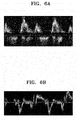
- FIGS. 6A and 6B show images obtained by changing a setting range according to a target area being observed.
- an ultrasound diagnosis apparatus may include first and second image processors that respectively acquire pieces of Doppler data with respect to two or more setting ranges based on one ultrasound signal (or echo signal). By combining together the acquired two or more pieces of Doppler data according to a predetermined method, it is possible to provide important information to the user.
- FIGS. 7A and 7B show images obtained by an ultrasound diagnosis apparatus by adjusting a setting range.
- Doppler is a method of observing a blood flow velocity using ultrasound waves. Furthermore, pulsed wave Doppler or continuous wave Doppler may be generally used for relatively accurate measurement of blood flow velocity. In this case, various setting values may be used to predict a range of a blood flow velocity or obtain a user's desired image. However, use of these setting values or setting ranges may cause the user to miss important information. Furthermore, when the user changes a setting to observe more information, unimportant information may be included and thus, the user may miss actual important information.
- an ultrasound diagnosis apparatus may respectively acquire pieces of Doppler data with respect to two setting ranges and process the acquired Doppler data by using a predetermined method, thereby enabling a user to easily identify important information.
- an ultrasound diagnosis apparatus may respectively acquire pieces of Doppler data with respect to two or more setting ranges.
- FIG. 8 shows an image for explaining a method, performed by an ultrasound diagnosis apparatus, of acquiring Doppler data with respect to a heart of an object.
- a waveform shown in FIG. 8 represents a pulsed wave Doppler signal.
- the pulsed wave Doppler signal may be used to display a blood flow image.
- a click signal is indicated by arrows and may be used to detect a valve signal. However, since the click signal is not clearly identified, it may not be easy to clearly provide a valve signal to the user.
- an example in which such a valve signal is extracted from a blood flow image and provided to the user according to an embodiment will be described.
- FIG. 9A illustrates a first image obtained based on first Doppler data
- FIG. 9B illustrates a second image obtained based on second Doppler data.
- FIG. 9C illustrates a feature extraction image obtained from a second image
- FIG. 9D illustrates a first resulting image obtained by adding the feature extraction image to the first image.
- the processor 420 may obtain the feature extraction image of FIG. 9C from the first image of FIG. 9A and the second image of FIG. 9B .
- the processor 420 may also obtain the first resulting image of FIG. 9D by adding the feature extraction image of FIG. 9C to the first or second image.
- FIG. 10 is a detailed flowchart of a method of operating the ultrasound diagnosis apparatus 400, according to an embodiment.
- Operation S170 described with reference to FIG. 5 may include operations S273 and S276.
- the processor 420 may determine the presence of an abnormality in the heart based on the first and second Doppler data (S273). In this case, to do so, the processor 420 may calculate a same volume interval in a cardiac cycle of the heart. For example, the processor 420 may determine the presence of an abnormality in the heart by determining a length of the same volume interval. In detail, the processor 420 may determine the presence of an abnormality in the heart by determining whether the length of the same volume interval is less than or equal to a reference value.
- the processor 420 may display a first resulting image based on a result of the determining in operation S273 (S276). For example, when any abnormality of the heart is present, the processor 420 may indicate the presence of an abnormality in the heart on the first resulting image by displaying a separate marker. For example, the processor 420 may indicate the presence of an abnormality in the heart on the first resulting image based on an input received via the user interface.
- FIG. 11 is a detailed flowchart of a method of operating the ultrasound diagnosis apparatus 400, according to an embodiment.
- Operation S170 described with reference to FIG. 5 may include operations S373 and S376.
- the processor 420 may transmit a difference between the first Doppler data and the second Doppler data to the display 430 (S373).
- the processor 420 may then display a first resulting image based on the difference between the first and second Doppler data (S376).
- FIG. 12 is a block diagram of a configuration of an ultrasound diagnosis apparatus according to another embodiment.
- the ultrasound diagnosis apparatus may include a Doppler signal receiver 510, a processor 520, and a display 530.
- the processor 520 may include a first image generator 525, a second image generator 523, and a feature extractor 527.
- FIG. 13 is a detailed flowchart of a method of operating the ultrasound diagnosis apparatus of FIG. 12 , according to an embodiment.
- the Doppler signal receiver 510 may receive an ultrasound signal to an object and receive an echo signal reflected from the heart (S210).
- the first image generator 525 may obtain a first image by acquiring Doppler data with respect to a first setting range
- the second image generator 523 may obtain a second image by acquiring Doppler data with respect to a second setting range (S230).
- the first image generator 525 may generate first Doppler data by transforming an echo signal received from a fetus's heart only within the first setting range and obtain the first image based on the first Doppler data.
- the second image generator 523 may generate second Doppler data by transforming the same echo signal that is used to obtain the first image only within the second setting range and obtain the second image based on the second Doppler data.
- image 1 as shown in FIG. 9A and image 2 as shown in FIG. 9B may be obtained.
- the feature extractor 527 may extract features from the second image (S270). By performing operation S270, a feature extraction image as shown in FIG. 9C may be obtained.
- the processor 520 may generate a resulting image by adding the extracted features to the first image (S290). By performing operation S290, an image representation as shown in FIG. 9D may be obtained.
- the first and second images may be processed using various methods.
- the number of images being processed is not limited to two (2) but may be implemented in various ways.
- the processor 520 may extract features by combining pieces of data regarding a plurality of images in various ways and generate a resulting image by combining the extracted features with differently processed data.
- the ultrasound diagnosis apparatuses described above may be implemented using hardware components, software components, and/or a combination thereof.
- the apparatuses and components illustrated in the embodiments may be implemented using one or more general-purpose or special-purpose computers, such as a processor, a controller, an arithmetic logic unit (ALU), a digital signal processor, a microcomputer, a field programmable array (FPA), a programmable logic unit (PLU), a microprocessor, or any other device capable of responding to and executing instructions.
- ALU arithmetic logic unit
- FPA field programmable array
- PLU programmable logic unit
- a processing device may run an operating system (OS) and one or more software applications running on the OS.
- the processing device may also access, store, manipulate, process, and create data in response to execution of software.
- OS operating system
- the processing device may also access, store, manipulate, process, and create data in response to execution of software.
- a processing device may include a plurality of processing elements and/or a plurality of types of processing elements.
- a processing device may include a plurality of processors or a processor and a controller.
- the processing device may have different processing configurations such as parallel processors.
- Software may include a computer program, a piece of code, an instruction, or one or more combinations thereof and independently or collectively instruct or configure the processing device to operate as desired.
- Software and/or data may be embodied permanently or temporarily in any type of machine, component, physical equipment, virtual equipment, computer storage medium or device, or in a transmitted signal wave so as to be interpreted by the processing device or to provide instructions or data to the processing device.
- the software may also be distributed over network-coupled computer systems so that the software is stored and executed in a distributed fashion.
- the software and data may be stored in one or more computer-readable recording media.
- the methods according to the embodiments may be recorded in non-transitory computer-readable recording media including program instructions to implement various operations embodied by a computer.
- the non-transitory computer-readable recording media may also include, alone or in combination with the program instructions, data files, data structures, and the like.
- the program instructions recorded in the non-transitory computer-readable recording media may be designed and configured specially for the embodiments or be known and available to those of ordinary skill in computer software.
- non-transitory computer-readable recording media include magnetic media such as hard disks, floppy disks, and magnetic tape, optical media such as CD-ROM discs and DVDs, magneto-optical media such as floptical discs, and hardware devices that are specially configured to store and perform program instructions, such as ROM, RAM, flash memory, and the like.
- Examples of program instructions include both machine code made by a compiler and a high-level programming language to be executed in the computer by using an interpreter.
- the above-described hardware devices may be configured to act as one or more software modules in order to perform the operations of the above-described embodiments, or vice versa.
Abstract
Description
- This application is based on and claims priority under 35 U.S.C. §119 to Korean Patent Application No.
10-2018-0013432, filed on February 2, 2018 - The disclosure relates to ultrasound diagnosis apparatuses and methods of operating the same.
- Ultrasound diagnosis apparatuses transmit ultrasound signals generated by transducers of a probe to an object and receive information about echo signals reflected from the object, thereby obtaining an image of an internal part of the object. In particular, ultrasound diagnosis apparatuses are used for medical purposes including observing an internal area of an object, detecting foreign substances, and assessing injuries. Such ultrasound diagnosis apparatuses exhibit high stability, display images in real time, and are safe due to there being no radiation exposure, compared to diagnostic X-ray apparatuses. Therefore, an ultrasound diagnosis apparatus is widely used together with other types of imaging diagnosis apparatuses.
- Provided are methods and apparatuses for ultrasound diagnosis apparatuses and methods that are used to further facilitate ultrasound diagnosis.
- Additional aspects will be set forth in part in the description which follows and, in part, will be apparent from the description, or may be learned by practice of the presented embodiments.
- In accordance with an aspect of the disclosure, a method of operating an ultrasound diagnosis apparatus includes:
claim 1 - In accordance with another aspect of the disclosure, an ultrasound diagnosis apparatus for performing diagnosis with respect to a heart of a fetus includes: claim 11
- In accordance with another aspect of the disclosure, a computer-readable recording medium has recorded thereon a program for performing a method of operating an ultrasound diagnosis apparatus, the method including: claim 21
- The above and other aspects, features, and advantages of certain embodiments of the present disclosure will be more apparent from the following description taken in conjunction with the accompanying drawings, in which:
-
FIG. 1 is a block diagram illustrating an ultrasound diagnosis apparatus according to an embodiment; -
FIGS. 2A, 2B, and 2C are diagrams respectively illustrating ultrasound diagnosis apparatuses according to an embodiment; -
FIG. 3 is a block diagram of a configuration of an ultrasound diagnosis apparatus according to an embodiment; -
FIG. 4 is a block diagram of a configuration of an ultrasound diagnosis apparatus according to another embodiment; -
FIG. 5 is a flowchart of a method of operating an ultrasound diagnosis apparatus, according to an embodiment; -
FIGS. 6A and 6B show images obtained by changing a setting range according to a target area being examined; -
FIGS. 7A and 7B show images obtained by an ultrasound diagnosis apparatus by adjusting a setting range; -
FIG. 8 shows an image for explaining a method, performed by an ultrasound diagnosis apparatus, of acquiring Doppler data with respect to a heart of an object; -
FIGS. 9A through 9D are images for explaining a first resulting image provided by an ultrasound diagnosis apparatus, according to an embodiment; -
FIG. 10 is a detailed flowchart of a method of operating an ultrasound diagnosis apparatus, according to an embodiment; -
FIG. 11 is a detailed flowchart of a method of operating an ultrasound diagnosis apparatus, according to an embodiment; -
FIG. 12 is a block diagram of a configuration of an ultrasound diagnosis apparatus according to another embodiment; and -
FIG. 13 is a detailed flowchart of a method of operating an ultrasound diagnosis apparatus, according to an embodiment. - Hereinafter, the terms used in the specification will be briefly described, and then the present invention will be described in detail. The terms used in this specification are those general terms currently widely used in the art in consideration of functions regarding the present invention, but the terms may vary according to the intention of those of ordinary skill in the art, precedents, or new technology in the art. Also, specified terms may be selected by the applicant, and in this case, the detailed meaning thereof will be described in the detailed description of the invention. Thus, the terms used in the specification should be understood not as simple names but based on the meaning of the terms and the overall description of the invention.
- Throughout the specification, it will also be understood that when a component "includes" an element, unless there is another opposite description thereto, it should be understood that the component does not exclude another element and may further include another element. In addition, terms such as "... unit", "... module", or the like refer to units that perform at least one function or operation, and the units may be implemented as hardware or software or as a combination of hardware and software.
- Also, the term "unit" in the specification means a software component or hardware component such as a field-programmable gate array (FPGA) or an application-specific integrated circuit (ASIC), and performs a specific function. However, the term "unit" is not limited to software or hardware. The "unit" may be formed so as to be in an addressable storage medium, or may be formed so as to operate one or more processors. Thus, for example, the term "unit" may refer to components such as software components, object-oriented software components, class components, and task components, and may include processes, functions, attributes, procedures, subroutines, segments of program code, drivers, firmware, micro codes, circuits, data, a database, data structures, tables, arrays, or variables. A function provided by the components and "units" may be associated with a smaller number of components and "units", or may be divided into additional components and "units".
- It will be understood that, although the terms "first", "second", etc. may be used herein to describe various elements and/or components, these elements and/or components should not be limited by these terms. These terms are only used to distinguish one element or component from another element or component. For example, a first element or component may be termed a second element or component or vice versa without departing from the teachings of embodiments. As used herein, the term "and/or" includes any and all combinations of one or more of the associated listed items. Expressions such as "at least one of," when preceding a list of elements, modify the entire list of elements and do not modify the individual elements of the list.
- Throughout the specification, an "image" may mean multi-dimensional data formed of discrete image elements (e.g., pixels in a two-dimensional (2D) image and voxels in a three-dimensional (3D) image).
- Throughout the specification, an "ultrasound image" refers to an image of an object, which is obtained using ultrasound waves. An ultrasound image may be an image obtained by transmitting ultrasound signals generated by transducers of a probe to an object and receiving information about echo signals reflected from the object. Furthermore, an ultrasound image may take different forms. For example, the ultrasound image may be at least one of an amplitude (A) mode image, a brightness (B) mode image, a color (C) mode image, and a Doppler (D) mode image. In addition, an ultrasound image may be a 2D or 3D image.
- Furthermore, an "object" may be a human, an animal, or a part of a human or animal. For example, the object may be an organ (e.g., the liver, the heart, the womb, the brain, a breast, or the abdomen), a blood vessel, or a combination thereof. Furthermore, the object may be a phantom. The phantom means a material having a density, an effective atomic number, and a volume that are approximately the same as those of an organism. For example, the phantom may be a spherical phantom having properties similar to a human body.
- Furthermore, throughout the specification, a "user" may be, but is not limited to, a medical expert, such as a medical doctor, a nurse, a medical laboratory technologist, a medical image expert, or a technician who repairs a medical apparatus
- Embodiments will be described more fully hereinafter with reference to the accompanying drawings so that they may be easily implemented by one of ordinary skill in the art. However, the embodiments may have different forms and should not be construed as being limited to the descriptions set forth herein.
- Embodiments of the invention now will be described more fully hereinafter with reference to the accompanying drawings, in which illustrative embodiments of the invention are shown.
-
FIG. 1 is a block diagram illustrating a configuration of anultrasound diagnosis apparatus 100, i.e., a diagnostic apparatus, according to an embodiment. - Referring to
FIG. 1 , theultrasound diagnosis apparatus 100 may include aprobe 20, anultrasound transceiver 110, acontroller 120, animage processor 130, one ormore displays 140, astorage 150, e.g., a memory, acommunicator 160, i.e., a communication device or an interface, and aninput interface 170. - The
ultrasound diagnosis apparatus 100 may be of a cart-type or a portable-type ultrasound diagnosis apparatus, that is portable, moveable, mobile, or hand-held. Examples of a portable-type ultrasound diagnosis apparatus may include a smart phone, a laptop computer, a personal digital assistant (PDA), and a tablet personal computer (PC), each of which may include a probe and a software application, but embodiments are not limited thereto. - The
probe 20 may include a plurality of transducers. The plurality of transducers may transmit ultrasound signals to anobject 10 in response to transmitting signals received by theprobe 20, from atransmitter 113. The plurality of transducers may receive ultrasound signals reflected from theobject 10 to generate reception signals. In addition, theprobe 20 and theultrasound diagnosis apparatus 100 may be formed in one body (e.g., disposed in a single housing), or theprobe 20 and theultrasound diagnosis apparatus 100 may be formed separately (e.g., disposed separately in separate housings) but linked wirelessly or via wires. In addition, theultrasound diagnosis apparatus 100 may include one ormore probes 20 according to embodiments. - The
controller 120 may control thetransmitter 113 for thetransmitter 113 to generate transmitting signals to be applied to each of the plurality of transducers based on a position and a focal point of the plurality of transducers included in theprobe 20. - The
controller 120 may control theultrasound receiver 115 to generate ultrasound data by converting reception signals received from theprobe 20 from analogue to digital signals and summing the reception signals converted into digital form, based on a position and a focal point of the plurality of transducers. - The
image processor 130 may generate an ultrasound image by using ultrasound data generated from theultrasound receiver 115. - The
display 140 may display a generated ultrasound image and various pieces of information processed by theultrasound diagnosis apparatus 100. Theultrasound diagnosis apparatus 100 may include two ormore displays 140 according to the present embodiment. Thedisplay 140 may include a touch screen in combination with a touch panel. - The
controller 120 may control the operations of theultrasound diagnosis apparatus 100 and flow of signals between the internal elements of theultrasound diagnosis apparatus 100. Thecontroller 120 may include a memory for storing a program or data to perform functions of theultrasound diagnosis apparatus 100 and a processor and/or a microprocessor (not shown) for processing the program or data. For example, thecontroller 120 may control the operation of theultrasound diagnosis apparatus 100 by receiving a control signal from theinput interface 170 or an external apparatus. - The
ultrasound diagnosis apparatus 100 may include thecommunicator 160 and may be connected to external apparatuses, for example, servers, medical apparatuses, and portable devices such as smart phones, tablet personal computers (PCs), wearable devices, etc., via thecommunicator 160. - The
communicator 160 may include at least one element capable of communicating with the external apparatuses. For example, thecommunicator 160 may include at least one among a short-range communication module, a wired communication module, and a wireless communication module. - The
communicator 160 may receive a control signal and data from an external apparatus and transmit the received control signal to thecontroller 120 so that thecontroller 120 may control theultrasound diagnosis apparatus 100 in response to the received control signal. - The
controller 120 may transmit a control signal to the external apparatus via thecommunicator 160 so that the external apparatus may be controlled in response to the control signal of thecontroller 120. - For example, the external apparatus connected to the
ultrasound diagnosis apparatus 100 may process the data of the external apparatus in response to the control signal of thecontroller 120 received via thecommunicator 160. - A program for controlling the
ultrasound diagnosis apparatus 100 may be installed in the external apparatus. The program may include command languages to perform part of operation of thecontroller 120 or the entire operation of thecontroller 120. - The program may be pre-installed in the external apparatus or may be installed by a user of the external apparatus by downloading the program from a server that provides applications. The server that provides applications may include a recording medium where the program is stored.
- The
storage 150 may store various data or programs for driving and controlling theultrasound diagnosis apparatus 100, input and/or output ultrasound data, ultrasound images, applications, etc. - The
input interface 170 may receive a user's input to control theultrasound diagnosis apparatus 100 and may include a keyboard, button, keypad, mouse, trackball, jog switch, knob, a touchpad, a touch screen, a microphone, a motion input means, a biometrics input means, etc. For example, the user's input may include inputs for manipulating buttons, keypads, mice, trackballs, jog switches, or knobs, inputs for touching a touchpad or a touch screen, a voice input, a motion input, and a bioinformation input, for example, iris recognition or fingerprint recognition, but an embodiment is not limited thereto. - An example of the
ultrasound diagnosis apparatus 100 according to the present embodiment is described below with reference toFIGS. 2A, 2B, and 2C . -
FIGS. 2A, 2B, and 2C are diagrams illustratingultrasound diagnosis apparatuses - Referring to
FIGS. 2A and 2B , theultrasound diagnosis apparatus 100a may include amain display 121 and a sub-display 122. At least one among themain display 121 and the sub-display 122 may include a touch screen. Themain display 121 and the sub-display 122 may display ultrasound images and/or various information processed by theultrasound diagnosis apparatus 100a. Themain display 121 and the sub-display 122 may provide graphical user interfaces (GUI), thereby receiving user's inputs of data to control theultrasound diagnosis apparatus 100a. For example, themain display 121 may display an ultrasound image and the sub-display 122 may display a control panel to control display of the ultrasound image as a GUI. The sub-display 122 may receive an input of data to control the display of an image through the control panel displayed as a GUI. Theultrasound diagnosis apparatus 100a may control the display of the ultrasound image on themain display 121 by using the input control data. - Referring to
FIG. 2B , theultrasound diagnosis apparatus 100b may include acontrol panel 165. Thecontrol panel 165 may include buttons, trackballs, jog switches, or knobs, and may receive data to control theultrasound diagnosis apparatus 100 from the user. For example, thecontrol panel 165 may include a time gain compensation (TGC) button 171 and afreeze button 172. The TGC button 171 is to set a TGC value for each depth of an ultrasound image. Also, when an input of thefreeze button 172 is detected during scanning an ultrasound image, theultrasound diagnosis apparatus 100 may keep displaying a frame image at that time point. - The buttons, trackballs, jog switches, and knobs included in the
control panel 165 may be provided as a GUI to themain display 121 or the sub-display 122. - Referring to
FIG. 2C , theultrasound diagnosis apparatus 100c may be implemented as a portable ultrasound diagnosis apparatus. An example of the portable ultrasound diagnosis apparatus may include, for example, smart phones including probes and applications, laptop computers, personal digital assistants (PDAs), or tablet PCs, but an embodiment is not limited thereto. - The
ultrasound diagnosis apparatus 100 may include theprobe 20 and amain body 40. Theprobe 20 may be connected to one side of themain body 40 by wire or wirelessly. Themain body 40 may include atouch screen 145. Thetouch screen 145 may display an ultrasound image, various pieces of information processed by theultrasound diagnosis apparatus 100, and a GUI. -
FIG. 3 is a block diagram of a configuration of anultrasound diagnosis apparatus 300 according to an embodiment. - Referring to
FIG. 3 , theultrasound diagnosis apparatus 300 according to the present embodiment may include aprobe 310, aprocessor 320, and adisplay 330. However, all of the components shown inFIG. 3 are not essential components. Theultrasound diagnosis apparatus 300 may include more or fewer components than those shown inFIG. 3 . Configurations and operations of theprobe 310, theprocessor 320, and thedisplay 330 will now be described in detail. - The
probe 310 may include a plurality of transducers that convert ultrasound signals into electrical signals or vice versa. In other words, theprobe 310 may include a transducer array consisting of a plurality of transducers. The plurality of transducers may be arranged in a one-dimensional (1D) or 2D array, and each of the plurality of transducers generates ultrasound signals separately or simultaneously. An ultrasound signal transmitted by each transducer is reflected off a discontinuous impedance surface within an object. Each transducer may convert a received reflected echo signal into an electrical reception signal. Theprobe 310 may transmit ultrasound signals to the heart of an object and receive echo signals reflected therefrom. In this case, the object may be a human. In detail, the object may include an adult, a child, a fetus, etc. - The
processor 320 may receive an echo signal from theprobe 310. Theprocessor 320 may then acquire first Doppler data with respect to a first setting range based on the received echo signal. Furthermore, theprocessor 320 may acquire second Doppler data with respect to a second setting range based on the echo signal. In this case, the first Doppler data may refer to data regarding blood flow of the heart, and the second Doppler data may refer to data regarding valves of the heart. - The
processor 320 may acquire data regarding a first resulting image to be displayed on thedisplay 330. Theprocessor 320 may acquire the data regarding the first resulting image based on the first Doppler data and the second Doppler data. For example, theprocessor 320 may acquire data regarding the first resulting image by using a difference between the first Doppler data and the second Doppler data. Theprocessor 320 may then transmit the data regarding the first resulting image to thedisplay 330. - The
display 330 displays a predetermined screen. In detail, thedisplay 330 may display a predetermined screen according to control by theprocessor 320. Thedisplay 330 includes a display panel (not shown) on which a resulting image (e.g., an ultrasound image or diagnostic image), etc. may be displayed. - The
ultrasound diagnosis apparatus 300 may include a central arithmetic processor that controls all operations of theprobe 310, theprocessor 320, and thedisplay 330. The central arithmetic processor may be implemented as an array of a plurality of logic gates or a combination of a general purpose microprocessor and a memory for storing a program that can be run on the general purpose microprocessor. Furthermore, it will be appreciated by those of ordinary skill in the art that the central arithmetic processor may be formed by different types of hardware. -
FIG. 4 is a block diagram of a configuration of anultrasound diagnosis apparatus 400 according to another embodiment. - Referring to
FIG. 4 , theultrasound diagnosis apparatus 400 according to the present embodiment may include aprobe 410, aprocessor 420, adisplay 430, afirst image processor 450, and asecond image processor 440. - Since the
probe 410, theprocessor 420, and thedisplay 430 included in theultrasound diagnosis apparatus 400 ofFIG. 1 respectively correspond to theprobe 310, theprocessor 320, and thedisplay 330 in theultrasound diagnosis apparatus 300 described with reference toFIG. 3 , descriptions that are provided above with respect toFIG. 3 will be omitted below. Theultrasound diagnosis apparatus 400 may include more or fewer components than those shown inFIG. 4 . - The
ultrasound diagnosis apparatus 400 may include the first andsecond image processors first image processor 450 may acquire first Doppler data with respect to a first setting range based on an echo signal. Thesecond image processor 440 may acquire second Doppler data with respect to a second setting range based on the same echo signal that is used by thefirst image processor 450. The first andsecond image processors processor 420. Unlike inFIG. 4 , the first andsecond image processors processor 420. - For example, the
first image processor 450 may generate data regarding a first image based on the first Doppler data. For example, thefirst image processor 450 may generate data regarding the first image by extracting data that satisfies the first setting range among the first Doppler data. - For example, the
second image processor 440 may generate data regarding a second image based on the second Doppler data. For example, thesecond image processor 440 may generate data regarding the second image by extracting data that satisfies the second setting range among the second Doppler data. - In this case, the first Doppler data and the second Doppler data are acquired by transforming the same echo signal or are generated therefrom. Thus, the
ultrasound diagnosis apparatus 400 according to the present embodiment may generate a resulting image via one-time diagnosis, thereby making it convenient for a user to perform diagnosis. - For example, the
processor 420 may extract features by comparing the data regarding the first image with the data regarding the second image. Theprocessor 420 may generate the first resulting image by adding the extracted features to the first image. The first resulting image may be generated using other various methods. - For example, the first or second setting range may mean a range of a setting value including at least one of a gain, a sensitivity, a power, and a blood flow velocity.
- The
ultrasound diagnosis apparatus 400 may further include a user interface (not shown). The user interface may refer to a device via which data for controlling theultrasound diagnosis apparatus 400 is received from the user. - The
processor 420 may control thedisplay 430 to generate and output a user interface screen for receiving a predetermined command or data from the user. Thedisplay 430 may display, on the display panel, an input screen for respectively setting landmarks corresponding to predetermined movements of the heart in the first and second Doppler data. In this case, the predetermined movements may be an opening movement of heart valves and flow of blood through the heart. - For example, the
ultrasound diagnosis apparatus 400 may further include a communicator (not shown). The communicator may receive and/or transmit data from and/or to an external device. For example, the communicator may transmit synchronized first and second Doppler data to an external terminal. Furthermore, the communicator may transmit at least one piece of data related to a function of the heart to the external terminal. In this case, the external terminal may be a patient's terminal. Furthermore, the external device a server for providing may be a relay server of an application for providing health information to a patient or a server that manages medical records of the patient. The communicator may connect to a wireless probe or an external device via a communication network based on Wi-Fi or Wi-Fi Direct (WFD) technology. In detail, examples of a wireless communication network to which the communicator can connect may include, but are not limited to, Wireless LAN (WLAN), Wi-Fi, Bluetooth, ZigBee, WFD, Ultra Wideband (UWB), Infrared Data Association (IrDA), Bluetooth Low Energy (BLE), and Near Field Communication (NFC). - The
ultrasound diagnosis apparatus 400 may further include a memory (not shown). The memory may store data related to an ultrasound image (e.g., an ultrasound image, ultrasound data, scan-related data, data related to diagnosis of a patient, etc.), data transmitted from an external device to theultrasound diagnosis apparatus 400, etc. The data transmitted from the external device may include patient-related information, data necessary for diagnosis and treatment of a patient, a patient's past medical history, a medical work list corresponding to instructions regarding diagnosis on a patient, and the like. - Furthermore, the memory may store a program for executing a method of operating the
ultrasound diagnosis apparatus 400. The memory may include a code representing a method of operating theultrasound diagnosis apparatus 400. - The
ultrasound diagnosis apparatus 400 may include a central arithmetic processor that controls all operations of theprobe 410, theprocessor 420, thedisplay 430, thefirst image processor 450, thesecond image processor 440, and the memory. The central arithmetic processor may be implemented as an array of a plurality of logic gates or a combination of a general purpose microprocessor and a memory for storing a program that can be executed on the general purpose microprocessor. Furthermore, it will be appreciated by those of ordinary skill in the art that the central arithmetic processor may be formed by different types of hardware. - Hereinafter, various operations performed by the ultrasound diagnosis apparatus 300 (400) and applications thereof will be described in detail. Although none of the probe 310 (410), the processor 320 (420), the display 330 (430), the user interface, the communicator, and the memory are specified, features and aspects that would be clearly understood by and are obvious to those of ordinary skill in the art may be considered as a typical implementation. The scope of the present disclosure is not limited by a name of a particular component or a physical/logical structure.
-
FIG. 5 is a flowchart of a method of operating an ultrasound diagnosis apparatus, according to an embodiment. - The method according to the present embodiment may include operations of: transmitting an ultrasound signal to an object and receiving an echo signal reflected from the heart (S110); acquiring first Doppler data with respect to a first setting range and second Doppler data with respect to a second setting range (S130); and displaying a first resulting image obtained based on the first and second Doppler data (S170).
- For example, in operations S130 and S170, the first and second setting ranges may each be ranges of a magnitude of a signal and a velocity of blood flow. Furthermore, the first Doppler data may be data in which a magnitude of a signal is a within a first range, and a velocity of blood flow is within a second range. The second Doppler data may be data in which the magnitude of the signal is within a third range, and the velocity of blood flow is within a third range.
- According to an embodiment, the first Doppler data may be acquired with respect to the first setting range by using an echo signal. Furthermore, the second Doppler data may be acquired with respect to the second setting range by using the same echo signal.
- According to an embodiment, in operation S170, to obtain the first resulting image, the
processor 420 may mix the first Doppler data with the second Doppler data according to a predetermined method. -
FIGS. 6A and 6B show images obtained by changing a setting range according to a target area being observed. - For example,
FIG. 6A may show an image obtained by optimizing a setting range for observation of a blood flow velocity, andFIG. 6B may show an image obtained by optimizing a setting range for observation of movement of an organ. In this way, the type of an image that can be obtained by the user varies according to a setting range. However, it may be inconvenient for a user to observe a plurality of these images or individually generate and observe the images. - According to an embodiment, as shown in
FIG. 4 , an ultrasound diagnosis apparatus may include first and second image processors that respectively acquire pieces of Doppler data with respect to two or more setting ranges based on one ultrasound signal (or echo signal). By combining together the acquired two or more pieces of Doppler data according to a predetermined method, it is possible to provide important information to the user. -
FIGS. 7A and 7B show images obtained by an ultrasound diagnosis apparatus by adjusting a setting range. - Doppler is a method of observing a blood flow velocity using ultrasound waves. Furthermore, pulsed wave Doppler or continuous wave Doppler may be generally used for relatively accurate measurement of blood flow velocity. In this case, various setting values may be used to predict a range of a blood flow velocity or obtain a user's desired image. However, use of these setting values or setting ranges may cause the user to miss important information. Furthermore, when the user changes a setting to observe more information, unimportant information may be included and thus, the user may miss actual important information.
- For example,
FIG. 7A may be an image obtained by generally adjusting a setting range for observation of blood flow, andFIG. 7B may be an image obtained by excessively adjusting a setting range. In other words, both general setting as shown inFIG. 7A and excessive setting as shown inFIG. 7B may make it difficult for the user to identify important information. - According to an embodiment, an ultrasound diagnosis apparatus may respectively acquire pieces of Doppler data with respect to two setting ranges and process the acquired Doppler data by using a predetermined method, thereby enabling a user to easily identify important information. According to another embodiment, an ultrasound diagnosis apparatus may respectively acquire pieces of Doppler data with respect to two or more setting ranges.
-
FIG. 8 shows an image for explaining a method, performed by an ultrasound diagnosis apparatus, of acquiring Doppler data with respect to a heart of an object. - A waveform shown in
FIG. 8 represents a pulsed wave Doppler signal. The pulsed wave Doppler signal may be used to display a blood flow image. A click signal is indicated by arrows and may be used to detect a valve signal. However, since the click signal is not clearly identified, it may not be easy to clearly provide a valve signal to the user. Hereinafter, an example in which such a valve signal is extracted from a blood flow image and provided to the user according to an embodiment will be described. -
FIGS. 9A through 9D show images for explaining a first resulting image provided by an ultrasound diagnosis apparatus, according to an embodiment. -
FIG. 9A illustrates a first image obtained based on first Doppler data, andFIG. 9B illustrates a second image obtained based on second Doppler data. -
FIG. 9C illustrates a feature extraction image obtained from a second image, andFIG. 9D illustrates a first resulting image obtained by adding the feature extraction image to the first image. - For example, the
processor 420 may obtain the feature extraction image ofFIG. 9C from the first image ofFIG. 9A and the second image ofFIG. 9B . Theprocessor 420 may also obtain the first resulting image ofFIG. 9D by adding the feature extraction image ofFIG. 9C to the first or second image. -
FIG. 10 is a detailed flowchart of a method of operating theultrasound diagnosis apparatus 400, according to an embodiment. - Operation S170 described with reference to
FIG. 5 may include operations S273 and S276. Referring toFIG. 10 , theprocessor 420 may determine the presence of an abnormality in the heart based on the first and second Doppler data (S273). In this case, to do so, theprocessor 420 may calculate a same volume interval in a cardiac cycle of the heart. For example, theprocessor 420 may determine the presence of an abnormality in the heart by determining a length of the same volume interval. In detail, theprocessor 420 may determine the presence of an abnormality in the heart by determining whether the length of the same volume interval is less than or equal to a reference value. - The
processor 420 may display a first resulting image based on a result of the determining in operation S273 (S276). For example, when any abnormality of the heart is present, theprocessor 420 may indicate the presence of an abnormality in the heart on the first resulting image by displaying a separate marker. For example, theprocessor 420 may indicate the presence of an abnormality in the heart on the first resulting image based on an input received via the user interface. -
FIG. 11 is a detailed flowchart of a method of operating theultrasound diagnosis apparatus 400, according to an embodiment. - Operation S170 described with reference to
FIG. 5 may include operations S373 and S376. Referring toFIG. 11 , theprocessor 420 may transmit a difference between the first Doppler data and the second Doppler data to the display 430 (S373). Theprocessor 420 may then display a first resulting image based on the difference between the first and second Doppler data (S376). -
FIG. 12 is a block diagram of a configuration of an ultrasound diagnosis apparatus according to another embodiment. - Referring to
FIG. 12 , the ultrasound diagnosis apparatus according to the present embodiment may include aDoppler signal receiver 510, aprocessor 520, and adisplay 530. Theprocessor 520 may include afirst image generator 525, asecond image generator 523, and afeature extractor 527. -
FIG. 13 is a detailed flowchart of a method of operating the ultrasound diagnosis apparatus ofFIG. 12 , according to an embodiment. - The
Doppler signal receiver 510 may receive an ultrasound signal to an object and receive an echo signal reflected from the heart (S210). - The
first image generator 525 may obtain a first image by acquiring Doppler data with respect to a first setting range, and thesecond image generator 523 may obtain a second image by acquiring Doppler data with respect to a second setting range (S230). - For example, the
first image generator 525 may generate first Doppler data by transforming an echo signal received from a fetus's heart only within the first setting range and obtain the first image based on the first Doppler data. Thesecond image generator 523 may generate second Doppler data by transforming the same echo signal that is used to obtain the first image only within the second setting range and obtain the second image based on the second Doppler data. - By performing these operations,
image 1 as shown inFIG. 9A andimage 2 as shown inFIG. 9B may be obtained. - The
feature extractor 527 may extract features from the second image (S270). By performing operation S270, a feature extraction image as shown inFIG. 9C may be obtained. Theprocessor 520 may generate a resulting image by adding the extracted features to the first image (S290). By performing operation S290, an image representation as shown inFIG. 9D may be obtained. - According to various embodiments, the first and second images may be processed using various methods. Furthermore, the number of images being processed is not limited to two (2) but may be implemented in various ways.
- According to various embodiments, the
processor 520 may extract features by combining pieces of data regarding a plurality of images in various ways and generate a resulting image by combining the extracted features with differently processed data. - The ultrasound diagnosis apparatuses described above may be implemented using hardware components, software components, and/or a combination thereof. For example, the apparatuses and components illustrated in the embodiments may be implemented using one or more general-purpose or special-purpose computers, such as a processor, a controller, an arithmetic logic unit (ALU), a digital signal processor, a microcomputer, a field programmable array (FPA), a programmable logic unit (PLU), a microprocessor, or any other device capable of responding to and executing instructions.
- A processing device may run an operating system (OS) and one or more software applications running on the OS. The processing device may also access, store, manipulate, process, and create data in response to execution of software.
- Although a single processing device may be illustrated for convenience, one of ordinary skill in the art will appreciate that a processing device may include a plurality of processing elements and/or a plurality of types of processing elements. For example, a processing device may include a plurality of processors or a processor and a controller. In addition, the processing device may have different processing configurations such as parallel processors.
- Software may include a computer program, a piece of code, an instruction, or one or more combinations thereof and independently or collectively instruct or configure the processing device to operate as desired.
- Software and/or data may be embodied permanently or temporarily in any type of machine, component, physical equipment, virtual equipment, computer storage medium or device, or in a transmitted signal wave so as to be interpreted by the processing device or to provide instructions or data to the processing device. The software may also be distributed over network-coupled computer systems so that the software is stored and executed in a distributed fashion. The software and data may be stored in one or more computer-readable recording media.
- The methods according to the embodiments may be recorded in non-transitory computer-readable recording media including program instructions to implement various operations embodied by a computer. The non-transitory computer-readable recording media may also include, alone or in combination with the program instructions, data files, data structures, and the like. The program instructions recorded in the non-transitory computer-readable recording media may be designed and configured specially for the embodiments or be known and available to those of ordinary skill in computer software.
- Examples of non-transitory computer-readable recording media include magnetic media such as hard disks, floppy disks, and magnetic tape, optical media such as CD-ROM discs and DVDs, magneto-optical media such as floptical discs, and hardware devices that are specially configured to store and perform program instructions, such as ROM, RAM, flash memory, and the like.
- Examples of program instructions include both machine code made by a compiler and a high-level programming language to be executed in the computer by using an interpreter.
- The above-described hardware devices may be configured to act as one or more software modules in order to perform the operations of the above-described embodiments, or vice versa.
- While one or more embodiments have been described with reference to the figures, it will be understood by those of ordinary skill in the art that various modifications and changes in form and details may be made from the above descriptions without departing from the spirit and scope as defined by the following claims. For example, adequate effects may be achieved even if the above techniques are performed in a different order than that described above, and/or the aforementioned elements, such as systems, structures, devices, or circuits, are combined or coupled in different forms and modes than those described above or are replaced or supplemented by other components or their equivalents.
- Thus, the scope of the present disclosure is defined not by the detailed description thereof but by the appended claims and their equivalents.
Claims (15)
- A method of operating an ultrasound diagnosis apparatus for performing diagnosis with respect to a heart of a fetus, the method comprising:transmitting an ultrasound signal to the heart of the fetus and receiving an echo signal reflected from the heart;acquiring first Doppler data and second Doppler data respectively with respect to first and second setting ranges by using the echo signal; anddisplaying a first resulting image obtained based on the first Doppler data and the second Doppler data.
- The method of claim 1, wherein the first Doppler data is data regarding blood flow of the heart, and the second Doppler data is data regarding valves of the heart.
- The method of claim 1, wherein the displaying of the first resulting image comprises:determining presence of an abnormality in the heart based on the first Doppler data and the second Doppler data; anddisplaying the first resulting image, based on a result of the determining.
- The method of claim 3, wherein the determining of the presence of the abnormality in the heart comprises determining the presence of the abnormality in the heart by calculating an isovolumic interval in a cardiac cycle of the heart.
- The method of claim 4, wherein the determining of the presence of the abnormality in the heart comprises determining the presence of the abnormality in the heart by determining whether the isovolumic interval is less than or equal to a predetermined time.
- The method of claim 1, wherein the displaying of the first resulting image comprises:transmitting a difference between the first Doppler data and the second Doppler data to a display; anddisplaying the first resulting image based on the difference between the first Doppler data and the second Doppler data.
- The method of claim 1, wherein the displaying of the first resulting image comprises:generating first image data and second image data respectively based on the first Doppler data and the second Doppler data; andgenerating feature extraction data representing properties of the heart, based on the first image data and the second image data.
- The method of claim 7, wherein the first resulting image is represented such that a user recognizes the properties of the heart from the feature extraction data.
- The method of claim 1, wherein the first and second setting ranges each include a range of a magnitude of a signal and a range of a velocity of blood flow, and
wherein the first and second Doppler data are each data in which the magnitude of the signal is within a predetermined range, and the velocity of the blood flow is within a predetermined range. - The method of claim 1, further comprising mixing the first Doppler data with the second Doppler data according to a predetermined method to obtain the first resulting image.
- An ultrasound diagnosis apparatus for performing diagnosis with respect to a heart of a fetus, the ultrasound diagnosis apparatus comprising:a probe configured to transmit an ultrasound signal to the heart of the fetus and receive an echo signal reflected from the heart;a processor configured to respectively acquire first Doppler data and second Doppler data with respect to first and second setting ranges by using the echo signal; anda display configured to display a first resulting image obtained based on the first Doppler data and the second Doppler data.
- The ultrasound diagnosis apparatus of claim 11, wherein the processor is further configured to determine presence of an abnormality in the heart, based on the first Doppler data and the second Doppler data, and
wherein the display is further configured to display the first resulting image based on a result of the determining. - The ultrasound diagnosis apparatus of claim 12, wherein the processor is further configured to determine the presence of the abnormality in the heart by calculating an isovolumic interval in a cardiac cycle of the heart.
- The ultrasound diagnosis apparatus of claim 13, wherein the processor is further configured to determine the presence of the abnormality in the heart by determining whether the isovolumic interval is less than or equal to a predetermined time.
- The ultrasound diagnosis apparatus of claim 11, wherein the processor is further configured to respectively generate first image data and second image data, based on the first Doppler data and the second Doppler data and produce feature extraction data representing properties of the heart, based on the first image data and the second image data.
Applications Claiming Priority (1)
| Application Number | Priority Date | Filing Date | Title |
|---|---|---|---|
| KR1020180013432A KR102575208B1 (en) | 2018-02-02 | 2018-02-02 | Ultrasound diagnosis apparatus and operating method for the same |
Publications (2)
| Publication Number | Publication Date |
|---|---|
| EP3520703A1 true EP3520703A1 (en) | 2019-08-07 |
| EP3520703B1 EP3520703B1 (en) | 2024-05-01 |
Family
ID=63579241
Family Applications (1)
| Application Number | Title | Priority Date | Filing Date |
|---|---|---|---|
| EP18194350.7A Active EP3520703B1 (en) | 2018-02-02 | 2018-09-13 | Ultrasound diagnosis apparatus and computer-readable recording medium storing a program for executing a method of operating same |
Country Status (3)
| Country | Link |
|---|---|
| US (1) | US20190239856A1 (en) |
| EP (1) | EP3520703B1 (en) |
| KR (1) | KR102575208B1 (en) |
Family Cites Families (3)
| Publication number | Priority date | Publication date | Assignee | Title |
|---|---|---|---|---|
| US8882671B2 (en) * | 2008-10-16 | 2014-11-11 | Kabushiki Kaisha Toshiba | Ultrasonic diagnostic device, ultrasonic image processing apparatus, ultrasonic image acquiring method and ultrasonic diagnosis display method |
| JP5788229B2 (en) * | 2011-06-06 | 2015-09-30 | 株式会社東芝 | Ultrasonic diagnostic equipment |
| WO2015076508A1 (en) * | 2013-11-21 | 2015-05-28 | Samsung Medison Co., Ltd. | Method and apparatus for displaying ultrasound image |
-
2018
- 2018-02-02 KR KR1020180013432A patent/KR102575208B1/en active IP Right Grant
- 2018-09-13 EP EP18194350.7A patent/EP3520703B1/en active Active
- 2018-10-09 US US16/155,168 patent/US20190239856A1/en not_active Abandoned
Non-Patent Citations (5)
| Title |
|---|
| BUI YEN K ET AL: "Tissue Doppler Is More Sensitive and Reproducible than Spectral Pulsed-Wave Doppler for Fetal Right Ventricle Myocardial Performance Index Determination in Normal and Diabetic Pregnancies", JOURNAL OF THE AMERICAN SOCIETY OF ECHOCARDIOGRAPHY, MOSBY-YEAR BOOK, INC. ST. LOUIS, MO, US, vol. 26, no. 5, 15 March 2013 (2013-03-15), pages 507 - 514, XP028585753, ISSN: 0894-7317, DOI: 10.1016/J.ECHO.2013.02.006 * |
| CHEN JIAO ET AL: "Right Heart Function of Fetuses and Infants with Large Ventricular Septal Defect: A Longitudinal Case-Control Study", PEDIATRIC CARDIOLOGY, SPRINGER NEW YORK LLC, US, vol. 37, no. 8, 25 August 2016 (2016-08-25), pages 1488 - 1497, XP036100341, ISSN: 0172-0643, [retrieved on 20160825], DOI: 10.1007/S00246-016-1462-Z * |
| E. HERNANDEZ-ANDRADE ET AL: "A modified myocardial performance (Tei) index based on the use of valve clicks improves reproducibility of fetal left cardiac function assessment : Reproducibility of a modified fetal myocardial performance index", ULTRASOUND IN OBSTETRICS AND GYNECOLOGY, vol. 26, no. 3, 22 August 2005 (2005-08-22), GB, pages 227 - 232, XP055583186, ISSN: 0960-7692, DOI: 10.1002/uog.1959 * |
| NAWAYTOU HYTHEM M ET AL: "Right Ventricular Systolic-to-Diastolic Time Index: Hypoplastic Left Heart Fetuses Differ Significantly from Normal Fetuses", JOURNAL OF THE AMERICAN SOCIETY OF ECHOCARDIOGRAPHY, MOSBY-YEAR BOOK, INC. ST. LOUIS, MO, US, vol. 29, no. 2, 26 September 2015 (2015-09-26), pages 143 - 149, XP029406958, ISSN: 0894-7317, DOI: 10.1016/J.ECHO.2015.08.014 * |
| T. KOGA ET AL: "A new and simple Doppler method for measurement of fetal cardiac isovolumetric contraction time : Fetal isovolumetric contraction time", ULTRASOUND IN OBSTETRICS AND GYNECOLOGY, vol. 18, no. 3, 1 September 2001 (2001-09-01), GB, pages 264 - 267, XP055582551, ISSN: 0960-7692, DOI: 10.1046/j.0960-7692.2001.00462.x * |
Also Published As
| Publication number | Publication date |
|---|---|
| EP3520703B1 (en) | 2024-05-01 |
| US20190239856A1 (en) | 2019-08-08 |
| KR20190093964A (en) | 2019-08-12 |
| KR102575208B1 (en) | 2023-09-07 |
Similar Documents
| Publication | Publication Date | Title |
|---|---|---|
| EP3653131B1 (en) | Ultrasound diagnosis apparatus for determining abnormality of fetal heart, and operating method thereof | |
| EP3114999A1 (en) | Apparatus and method of processing medical image | |
| US10806433B2 (en) | Ultrasound apparatus and method of operating the same | |
| EP3420913B1 (en) | Ultrasound imaging apparatus and control method thereof | |
| EP3184050B1 (en) | Method and apparatus for displaying ultrasound images | |
| US11013494B2 (en) | Ultrasound imaging apparatus and ultrasound image display method | |
| EP3673813B1 (en) | Ultrasound diagnosis apparatus | |
| CN107809956B (en) | Ultrasound device and method of operating the same | |
| EP3520704B1 (en) | Ultrasound diagnosis apparatus and method of controlling the same | |
| EP3542724A1 (en) | Ultrasonic diagnostic device and operation method thereof | |
| US11096667B2 (en) | Ultrasound imaging apparatus and method of controlling the same | |
| EP3510936A1 (en) | Ultrasound imaging apparatus and method of controlling the same | |
| EP3689246A1 (en) | Ultrasound diagnosis apparatus and method of operating the same | |
| US10514450B2 (en) | Ultrasound apparatus and operating method thereof | |
| EP3520703B1 (en) | Ultrasound diagnosis apparatus and computer-readable recording medium storing a program for executing a method of operating same | |
| US11844646B2 (en) | Ultrasound diagnosis apparatus and operating method for the same | |
| EP3851051B1 (en) | Ultrasound diagnosis apparatus and operating method thereof |
Legal Events
| Date | Code | Title | Description |
|---|---|---|---|
| PUAI | Public reference made under article 153(3) epc to a published international application that has entered the european phase |
Free format text: ORIGINAL CODE: 0009012 |
|
| STAA | Information on the status of an ep patent application or granted ep patent |
Free format text: STATUS: THE APPLICATION HAS BEEN PUBLISHED |
|
| AK | Designated contracting states |
Kind code of ref document: A1 Designated state(s): AL AT BE BG CH CY CZ DE DK EE ES FI FR GB GR HR HU IE IS IT LI LT LU LV MC MK MT NL NO PL PT RO RS SE SI SK SM TR |
|
| AX | Request for extension of the european patent |
Extension state: BA ME |
|
| STAA | Information on the status of an ep patent application or granted ep patent |
Free format text: STATUS: REQUEST FOR EXAMINATION WAS MADE |
|
| 17P | Request for examination filed |
Effective date: 20200131 |
|
| RBV | Designated contracting states (corrected) |
Designated state(s): AL AT BE BG CH CY CZ DE DK EE ES FI FR GB GR HR HU IE IS IT LI LT LU LV MC MK MT NL NO PL PT RO RS SE SI SK SM TR |
|
| STAA | Information on the status of an ep patent application or granted ep patent |
Free format text: STATUS: EXAMINATION IS IN PROGRESS |
|
| 17Q | First examination report despatched |
Effective date: 20220518 |
|
| GRAP | Despatch of communication of intention to grant a patent |
Free format text: ORIGINAL CODE: EPIDOSNIGR1 |
|
| STAA | Information on the status of an ep patent application or granted ep patent |
Free format text: STATUS: GRANT OF PATENT IS INTENDED |
|
| INTG | Intention to grant announced |
Effective date: 20231213 |
|
| GRAS | Grant fee paid |
Free format text: ORIGINAL CODE: EPIDOSNIGR3 |
|
| GRAA | (expected) grant |
Free format text: ORIGINAL CODE: 0009210 |
|
| STAA | Information on the status of an ep patent application or granted ep patent |
Free format text: STATUS: THE PATENT HAS BEEN GRANTED |