EP3520702A1 - Method of obtaining contrast image and ultrasound diagnosis apparatus for performing the method - Google Patents
Method of obtaining contrast image and ultrasound diagnosis apparatus for performing the method Download PDFInfo
- Publication number
- EP3520702A1 EP3520702A1 EP18186063.6A EP18186063A EP3520702A1 EP 3520702 A1 EP3520702 A1 EP 3520702A1 EP 18186063 A EP18186063 A EP 18186063A EP 3520702 A1 EP3520702 A1 EP 3520702A1
- Authority
- EP
- European Patent Office
- Prior art keywords
- roi
- image
- ultrasound
- contrast
- diagnosis apparatus
- Prior art date
- Legal status (The legal status is an assumption and is not a legal conclusion. Google has not performed a legal analysis and makes no representation as to the accuracy of the status listed.)
- Granted
Links
- 238000002604 ultrasonography Methods 0.000 title claims abstract description 220
- 238000003745 diagnosis Methods 0.000 title claims abstract description 118
- 238000000034 method Methods 0.000 title claims abstract description 31
- 239000002872 contrast media Substances 0.000 claims abstract description 102
- 239000000523 sample Substances 0.000 claims description 30
- 238000003384 imaging method Methods 0.000 claims description 25
- 206010028980 Neoplasm Diseases 0.000 description 13
- 210000004204 blood vessel Anatomy 0.000 description 11
- 230000003902 lesion Effects 0.000 description 8
- 210000001519 tissue Anatomy 0.000 description 7
- 230000004044 response Effects 0.000 description 6
- 238000004891 communication Methods 0.000 description 5
- 210000000056 organ Anatomy 0.000 description 4
- 230000005540 biological transmission Effects 0.000 description 2
- 238000002591 computed tomography Methods 0.000 description 2
- 238000010586 diagram Methods 0.000 description 2
- 238000012285 ultrasound imaging Methods 0.000 description 2
- 241001465754 Metazoa Species 0.000 description 1
- 241000699670 Mus sp. Species 0.000 description 1
- 230000017531 blood circulation Effects 0.000 description 1
- 238000002607 contrast-enhanced ultrasound Methods 0.000 description 1
- 230000006378 damage Effects 0.000 description 1
- 238000002059 diagnostic imaging Methods 0.000 description 1
- 238000005516 engineering process Methods 0.000 description 1
- 230000006870 function Effects 0.000 description 1
- 230000014509 gene expression Effects 0.000 description 1
- 238000002347 injection Methods 0.000 description 1
- 239000007924 injection Substances 0.000 description 1
- 238000002595 magnetic resonance imaging Methods 0.000 description 1
- 230000007246 mechanism Effects 0.000 description 1
- 238000012986 modification Methods 0.000 description 1
- 230000004048 modification Effects 0.000 description 1
- 230000008569 process Effects 0.000 description 1
- 210000004872 soft tissue Anatomy 0.000 description 1
- 239000000126 substance Substances 0.000 description 1
- 210000003462 vein Anatomy 0.000 description 1
Images


Classifications
-
- A—HUMAN NECESSITIES
- A61—MEDICAL OR VETERINARY SCIENCE; HYGIENE
- A61B—DIAGNOSIS; SURGERY; IDENTIFICATION
- A61B8/00—Diagnosis using ultrasonic, sonic or infrasonic waves
- A61B8/54—Control of the diagnostic device
-
- A—HUMAN NECESSITIES
- A61—MEDICAL OR VETERINARY SCIENCE; HYGIENE
- A61B—DIAGNOSIS; SURGERY; IDENTIFICATION
- A61B8/00—Diagnosis using ultrasonic, sonic or infrasonic waves
- A61B8/44—Constructional features of the ultrasonic, sonic or infrasonic diagnostic device
- A61B8/4483—Constructional features of the ultrasonic, sonic or infrasonic diagnostic device characterised by features of the ultrasound transducer
-
- A—HUMAN NECESSITIES
- A61—MEDICAL OR VETERINARY SCIENCE; HYGIENE
- A61B—DIAGNOSIS; SURGERY; IDENTIFICATION
- A61B8/00—Diagnosis using ultrasonic, sonic or infrasonic waves
- A61B8/46—Ultrasonic, sonic or infrasonic diagnostic devices with special arrangements for interfacing with the operator or the patient
- A61B8/461—Displaying means of special interest
- A61B8/463—Displaying means of special interest characterised by displaying multiple images or images and diagnostic data on one display
-
- A—HUMAN NECESSITIES
- A61—MEDICAL OR VETERINARY SCIENCE; HYGIENE
- A61B—DIAGNOSIS; SURGERY; IDENTIFICATION
- A61B8/00—Diagnosis using ultrasonic, sonic or infrasonic waves
- A61B8/46—Ultrasonic, sonic or infrasonic diagnostic devices with special arrangements for interfacing with the operator or the patient
- A61B8/467—Ultrasonic, sonic or infrasonic diagnostic devices with special arrangements for interfacing with the operator or the patient characterised by special input means
- A61B8/469—Ultrasonic, sonic or infrasonic diagnostic devices with special arrangements for interfacing with the operator or the patient characterised by special input means for selection of a region of interest
-
- A—HUMAN NECESSITIES
- A61—MEDICAL OR VETERINARY SCIENCE; HYGIENE
- A61B—DIAGNOSIS; SURGERY; IDENTIFICATION
- A61B8/00—Diagnosis using ultrasonic, sonic or infrasonic waves
- A61B8/48—Diagnostic techniques
- A61B8/481—Diagnostic techniques involving the use of contrast agent, e.g. microbubbles introduced into the bloodstream
-
- A—HUMAN NECESSITIES
- A61—MEDICAL OR VETERINARY SCIENCE; HYGIENE
- A61B—DIAGNOSIS; SURGERY; IDENTIFICATION
- A61B8/00—Diagnosis using ultrasonic, sonic or infrasonic waves
- A61B8/48—Diagnostic techniques
- A61B8/488—Diagnostic techniques involving Doppler signals
-
- A—HUMAN NECESSITIES
- A61—MEDICAL OR VETERINARY SCIENCE; HYGIENE
- A61B—DIAGNOSIS; SURGERY; IDENTIFICATION
- A61B8/00—Diagnosis using ultrasonic, sonic or infrasonic waves
- A61B8/52—Devices using data or image processing specially adapted for diagnosis using ultrasonic, sonic or infrasonic waves
- A61B8/5207—Devices using data or image processing specially adapted for diagnosis using ultrasonic, sonic or infrasonic waves involving processing of raw data to produce diagnostic data, e.g. for generating an image
-
- A—HUMAN NECESSITIES
- A61—MEDICAL OR VETERINARY SCIENCE; HYGIENE
- A61B—DIAGNOSIS; SURGERY; IDENTIFICATION
- A61B8/00—Diagnosis using ultrasonic, sonic or infrasonic waves
- A61B8/52—Devices using data or image processing specially adapted for diagnosis using ultrasonic, sonic or infrasonic waves
- A61B8/5215—Devices using data or image processing specially adapted for diagnosis using ultrasonic, sonic or infrasonic waves involving processing of medical diagnostic data
- A61B8/5238—Devices using data or image processing specially adapted for diagnosis using ultrasonic, sonic or infrasonic waves involving processing of medical diagnostic data for combining image data of patient, e.g. merging several images from different acquisition modes into one image
- A61B8/5246—Devices using data or image processing specially adapted for diagnosis using ultrasonic, sonic or infrasonic waves involving processing of medical diagnostic data for combining image data of patient, e.g. merging several images from different acquisition modes into one image combining images from the same or different imaging techniques, e.g. color Doppler and B-mode
-
- G—PHYSICS
- G01—MEASURING; TESTING
- G01S—RADIO DIRECTION-FINDING; RADIO NAVIGATION; DETERMINING DISTANCE OR VELOCITY BY USE OF RADIO WAVES; LOCATING OR PRESENCE-DETECTING BY USE OF THE REFLECTION OR RERADIATION OF RADIO WAVES; ANALOGOUS ARRANGEMENTS USING OTHER WAVES
- G01S15/00—Systems using the reflection or reradiation of acoustic waves, e.g. sonar systems
- G01S15/88—Sonar systems specially adapted for specific applications
- G01S15/89—Sonar systems specially adapted for specific applications for mapping or imaging
- G01S15/8906—Short-range imaging systems; Acoustic microscope systems using pulse-echo techniques
- G01S15/8979—Combined Doppler and pulse-echo imaging systems
- G01S15/8988—Colour Doppler imaging
Definitions
- One or more embodiments relate to a method of obtaining a contrast image and an ultrasound diagnosis apparatus for performing the method, and more particularly, to a method of flashing a contrast agent and an ultrasound diagnosis apparatus for performing the method.
- An ultrasound diagnosis apparatus applies an ultrasound signal generated by a transducer of a probe to an object and receives information of a signal reflected from the object, to obtain at least one image of a body part (e.g., soft tissue or blood flow) inside the object.
- a body part e.g., soft tissue or blood flow
- 'contrast-enhanced ultrasound image' or 'contrast image' may refer to an image obtained by injecting a contrast agent into veins, etc. of an object, transmitting an ultrasound signal to blood vessels of the object, and imaging a reflective signal of the contrast agent that vibrates in the blood vessels.
- a contrast agent or a contrast medium that is a chemical substance for increasing a contrast of an image to improve the visibility of tissue or blood vessels during a computer-tomography (CT) scan or a magnetic resonance imaging (MRI) scan may be used to clearly distinguish a biological structure or a lesion from surrounding tissue.
- CT computer-tomography
- MRI magnetic resonance imaging
- One or more embodiments include an apparatus and method for reducing destruction of a contrast agent during contrast imaging.
- one or more embodiments include an apparatus and method for frequently showing the flow of a contrast agent to a lesion during contrast imaging.
- one or more embodiments include an apparatus and method for easily setting a region of interest (ROI) during contrast imaging.
- ROI region of interest
- an ultrasound diagnosis apparatus includes: an ultrasound transceiver; a display; and a controller configured to obtain an ultrasound image and a contrast image of an object by using the ultrasound transceiver, determine a region of interest (ROI) in at least one of the ultrasound image and the contrast image, transmit a flash pulse to destroy a contrast agent in the ROI from among regions of the object, image the contrast agent re-introduced into the ROI, and control the display to display the contrast image of the ROI.
- ROI region of interest
- the controller may be further configured to transmit the flash pulse to destroy the contrast agent in the ROI by controlling a probe to transmit the flash pulse from transducer elements corresponding to the ROI from among a plurality of transducer elements of the probe.
- the controller may be further configured to transmit the flash pulse to destroy the contrast agent in the ROI by determining the ROI as a focusing region and performing beamforming based on the determined focusing region.
- the controller may be further configured to receive a user input that adjusts a mechanical index of the flash pulse and transmit the flash pulse having the adjusted mechanical index.
- the controller may be further configured to control the display to display an image indicating the ROI in the ultrasound image at a position of the ROI in the contrast image.
- the ultrasound diagnosis apparatus may further include a user input interface configured to receive a user input for setting the ROI in the at least one of the ultrasound image and the contrast image of the object.
- the controller may be further configured to, when a user input that measures a certain region in the ultrasound image is received, determine the measured certain region as the ROI.
- the ultrasound image may be a color Doppler image
- the controller may be further configured to determine a region where a color Doppler flow in the color Doppler image is displayed as the ROI.
- the controller may be further configured to control the display to display the ultrasound image and the contrast image together and display a position of a region in the ultrasound image corresponding to the ROI set in the contrast image, on the ultrasound image.
- the controller may be further configured to, when the ROI is determined, display an expected contrast image to be obtained when the flash pulse is transmitted to the determined ROI.
- an image may include any medical image acquired by a medical imaging apparatus such as an ultrasound imaging apparatus.
- an 'object' which is a thing to be imaged, may include a human, an animal, or a part thereof.
- an object may include a part of a human (e.g., an organ) or a phantom.
- an "ultrasound image” refers to an image of an object processed based on an ultrasound signal transmitted to the object and reflected therefrom.
- the term "and/or” includes any and all combinations of one or more of the associated listed items. Expressions such as “at least one of”, when preceding a list of elements, modify the entire list of elements and do not modify the individual elements of the list.
- FIG. 1 is a view for explaining a method by which an ultrasound diagnosis apparatus 100 removes only a contrast agent of a certain region in a scan region during contrast imaging, according to an embodiment.
- a contrast image may show a flow of the contrast agent, and the flow of the contrast agent may reveal a location, a shape, or characteristics of a lesion. For example, since tumor tissue includes more blood vessels than surrounding tissue, a larger amount of contrast agent may be introduced into the tumor tissue, thereby making the tumor tissue brighter than the surrounding tissue.
- the amount of contrast agent passing through organs and remaining in the body may gradually decrease as time passes. For example, when a contrast agent is not artificially destroyed, the contrast agent may remain in the body for about 5 minutes.
- a user may monitor again a flow of the contrast agent introduced into the scan region by flashing the contrast agent in the scan region. Also, as the amount of contrast agent remaining in the body is reduced, in order to rapidly destroy the contrast agent in the body in a short time for the purpose of re-injection of the contrast agent, the user may remove the contrast agent remaining in the body in a short time by flashing the contrast agent in the scan region several times.
- the term 'flashing' may refer to transmitting an ultrasound pulse with a mechanical index (MI) great enough to destroy the contrast agent into the body.
- the ultrasound diagnosis apparatus 100 may destroy the contrast agent in the scan region by transmitting an ultrasound pulse with an MI of 1.8 to the scan region.
- the term 'MI' may refer to a peak negative pressure of an ultrasound signal.
- the ultrasound pulse for destroying the contrast agent may be referred to as a flash pulse.
- the contrast agent may be more easily destroyed by a flash pulse with a greater MI.
- the contrast agent may not be destroyed by a flash pulse with an MI equal to or less than a reference value.
- a region of interest (ROI) of the user may be a certain region in the scan region, instead of the entire scan region. Also, according to cases, the user may want to see a flow of the contrast agent introduced into the entire scan region or may want to see a flow of the contrast agent introduced into a certain ROI of the scan region.
- ROI region of interest
- the amount of contrast agent that is destroyed may increase. As the amount of contrast agent that is destroyed increases, a cycle in which the contrast agent is re-injected may decrease. Also, if the entire scan region is flashed, a time taken for the contrast agent to be introduced into the ROI after flashing may increase, thereby increasing a contrast imaging time.
- the ultrasound diagnosis apparatus 100 may remove only a contrast agent of a certain region of a scan region 40 during contrast imaging.
- the ultrasound diagnosis apparatus 100 may flash only the contrast agent in the ROI 30 of the entire scan region 40.
- the amount of contrast agent that is destroyed in the body may be reduced and a cycle in which the contrast agent is re-introduced into the ROI 30 may also be reduced.
- FIG. 2 is a view for explaining a method by which the ultrasound diagnosis apparatus 100 displays a contrast image of the ROI 30 by flashing only a contrast agent of the ROI 30 of a scan region, according to an embodiment.
- a user may check a region of a lesion 5 to be scanned based on a B-mode image 60 before contrast imaging.
- the ultrasound diagnosis apparatus 100 may transmit an ultrasound signal for B-mode imaging to an object and may generate and display the B-mode image 60 based on an echo signal received from the object.
- the ultrasound diagnosis apparatus 100 may transmit an ultrasound signal for contrast imaging to the object and may generate and display the contrast image 50 based on an echo signal received from the object.
- the user may inject a contrast agent into the object before B-mode imaging, and may inject the contrast agent into the object before contrast imaging after the B-mode imaging. Also, the user may start the contrast imaging at the same position as a position of a probe during the B-mode imaging, without changing the position of the probe after the B-mode imaging.
- the contrast agent As the contrast agent is introduced into the scan region, the contrast agent may be first introduced into an organ 9, a thick blood vessel 7, or a tumor 5 having thick blood vessels and a high density. Accordingly, in the obtained contrast image 50, the lesion 5, the thick blood vessel 7, and the organ 9 in the scan region may look brighter than other regions.
- the user may determine a type of the tumor 5 based on a speed or characteristics of the contrast agent that is introduced. For example, the user may determine a type of the tumor 5 based on whether a brightness level gradually increases from the inside of the tumor 5 to the outside of the tumor 5 or gradually increases from the outside of the tumor 5 to the inside of the tumor 5.
- the ultrasound diagnosis apparatus 100 may flash only the contrast agent in the ROI 30 of the scan region.
- the ROI 30 may be set by the user, or may be automatically determined by the ultrasound diagnosis apparatus 100 according to the user's manipulation of the B-mode image 60.
- the ROI 30 may be a region where the tumor 5 is located.
- the ROI 30 on the contrast image may be in black and white and regions other than the ROI 30 may be bright.
- the contrast image 50 may show again a flow of the contrast agent introduced into the tumor 5.
- FIG. 3 is a flowchart of a method by which the ultrasound diagnosis apparatus 100 flashes a contrast agent located in an ROI of a scan region, according to an embodiment.
- the ultrasound diagnosis apparatus 100 may obtain an ultrasound image of an object and a contrast image of the object.
- the ultrasound image may include a B-mode image, an M-mode image, and a Doppler image.
- the ultrasound image and the contrast image may be two-dimensional (2D) images or three-dimensional (3D) images.
- the ultrasound diagnosis apparatus 100 may include a menu or a button for obtaining the ultrasound image and the contrast image.
- the ultrasound diagnosis apparatus 100 may obtain the ultrasound image of a scan region by transmitting a first ultrasound signal to the object and receiving an ultrasound echo signal from the object.
- the ultrasound diagnosis apparatus 100 may obtain the contrast image of the scan region by transmitting a second ultrasound signal to the object and receiving an ultrasound echo signal reflected from the contrast agent in the object.
- the first ultrasound signal and the second ultrasound signal may be different from each other.
- the ultrasound diagnosis apparatus 100 may display the ultrasound image and the contrast image together. Also, according to embodiments, when a toggle mode is provided, the ultrasound diagnosis apparatus 10 may alternately display the ultrasound image and the contrast image based on a user input that selects a toggle button. Also, according to embodiments, the ultrasound diagnosis apparatus 100 may display the ultrasound image and the contrast image so that the ultrasound image and the contrast image overlap each other.
- the ultrasound diagnosis apparatus 100 may determine an ROI in at least one of the ultrasound image and the contrast image.
- the ultrasound diagnosis apparatus 100 may receive a user input that sets the ROI in at least one of the ultrasound image and the contrast image. For example, the ultrasound diagnosis apparatus 100 may provide a menu for setting a region to be flashed to at least one of the ultrasound image and the contrast image.
- the ultrasound diagnosis apparatus 100 may receive a user input that sets the ROI on the ultrasound image, or may receive a user input that sets the ROI on the contrast image.
- the ultrasound diagnosis apparatus 100 may automatically determine the measured certain region as the ROI. Also, the ultrasound diagnosis apparatus 100 may provide guide information for checking whether the measured certain region is to be set as the ROI and may determine the measured certain region as the ROI based on a user response.
- the ultrasound diagnosis apparatus 100 may determine the enlarged certain region as the ROI. Also, the ultrasound diagnosis apparatus 100 may provide guide information for checking whether the enlarged certain region is to be set as the ROI and may determine the enlarged certain region as the ROI based on a user response.
- the ultrasound diagnosis apparatus 100 may automatically determine a region where a color Doppler flow in the color Doppler image is displayed as the ROI. Also, when the ultrasound image is a color Doppler image, the ultrasound diagnosis apparatus 100 may automatically determine a region set by the user in the color Doppler image as the ROI. Once the ultrasound diagnosis apparatus 100 automatically determines the ROI, the ultrasound diagnosis apparatus 100 may display the determined ROI so that the user may check the ROI.
- the ROI may have, but is not limited to, a box shape, a circular shape, or a scan line shape.
- a plurality of the ROIs may be provided.
- the number of ROIs may be 2, 3, 4, or more.
- the ultrasound diagnosis apparatus 100 may transmit a flash pulse to destroy the contrast agent in the ROI from among regions of the object.
- the ultrasound diagnosis apparatus 100 may receive a user input for transmitting the flash pulse to the object.
- the ultrasound diagnosis apparatus 100 may include a menu or a button for transmitting the flash pulse to the object.
- the ultrasound diagnosis apparatus 100 may transmit the flash pulse to destroy the contrast agent in the ROI by controlling a probe to transmit the flash pulse from transducer elements corresponding to the ROI from among all transducer elements of the probe.
- the transducer elements may be referred to as elements or probe elements according to embodiments.
- the ultrasound diagnosis apparatus 100 may transmit the flash pulse to destroy the contrast agent in the ROI by determining the ROI as a focusing region and performing beamforming based on the focusing region.
- the ultrasound diagnosis apparatus 100 may transmit the flash pulse to the same ROI two or more times. For example, as a user input for destroying the contrast agent in the ROI is received, the ultrasound diagnosis apparatus 100 may transmit the flash pulse to the same ROI a preset number of times. The number of times the flash pulse is transmitted may be determined by a user input.
- the contrast agent located in a region through which the flash pulse transmitted from the transducer elements passes before reaching the ROI or a region through which the flash pulse is passes after reaching the ROI may also be destroyed.
- the ROI has a scan line shape
- the contrast agent located in a surrounding region outside the ROI may also be destroyed. Accordingly, even when the ultrasound diagnosis apparatus 100 transmits the flash pulse to destroy the contrast agent in the ROI from among the regions of the object, the contrast agent located in the surrounding region outside the ROI may also be destroyed.
- a total size of the ROI and the surrounding region outside the ROI is much less than a size of the entire scan region, the amount of contrast agent that is destroyed may be reduced.
- the ultrasound diagnosis apparatus 100 may display an expected contrast image to be obtained when the flash pulse is transmitted to the determined ROI. For example, the ultrasound diagnosis apparatus 100 may extract frame data displayed on the ROI of the contrast image based on the contrast image obtained in operation S310, may generate a video corresponding to the ROI based on the extracted frame data, and may display the generated video on the ROI of the expected contrast image.
- the ultrasound diagnosis apparatus 100 may provide a user interface for adjusting an MI of the flash pulse.
- the ultrasound diagnosis apparatus 100 may receive a user input that adjusts the MI of the flash pulse through the user interface and may transmit the flash pulse having the adjusted MI to the object.
- the ultrasound diagnosis apparatus 100 may display the expected contrast image to be obtained when the flash pulse having the adjusted MI is transmitted.
- the ultrasound diagnosis apparatus 100 may display the contrast image of the ROI by imaging the contrast agent re-introduced into the ROI.
- the ultrasound diagnosis apparatus 100 may generate the contrast image of the scan region by transmitting a second ultrasound signal to the object and receiving an ultrasound echo signal from the contrast agent in the object.
- the contrast image may show a flow of the contrast agent introduced into the ROI.
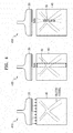
- FIG. 4 is a view for explaining a method by which the ultrasound diagnosis apparatus 100 transmits a flash pulse to destroy only a contrast agent located in an ROI of a scan region, according to an embodiment.
- the ultrasound diagnosis apparatus 100 may destroy a contrast agent located in the entire scan region 40 by transmitting a flash pulse to the entire scan region 40.
- the ultrasound diagnosis apparatus 100 may control a probe 20 to transmit the flash pulse to the entire scan region 40 from all transducer elements located in the probe 20.
- the ultrasound diagnosis apparatus 100 may transmit the flash pulse to destroy only the contrast agent located in the ROI 30 of the scan region 40.
- the ultrasound diagnosis apparatus 100 may transmit the flash pulse to destroy the contrast agent in the ROI 30 by controlling a transceiver to transmit the flash pulse only from transducer elements corresponding to the ROI 30 from among a plurality of transducer elements of the probe 20.
- the ultrasound diagnosis apparatus 100 may determine transducer elements located within a pre-determined distance from a transducer element that is the closest to the ROI 30 from among the plurality of transducer elements as the transducer elements corresponding to the ROI 30, based on a position of the ROI 30.
- the ultrasound diagnosis apparatus 100 may determine scan lines over which the ROI 30 extends from among a plurality of scan lines constituting an ultrasound image or a contrast image, and may determine transducer elements located within a pre-determined distance from the determined scan lines as the transducer elements corresponding to the ROI 30.
- the ultrasound diagnosis apparatus 100 may transmit the flash pulse to destroy the contrast agent in the ROI 30 by determining the ROI 30 as a focusing region and performing beamforming based on the focusing region.
- the ultrasound diagnosis apparatus 100 may destroy the contrast agent in the plurality of ROIs by determining transducer elements respectively corresponding to the plurality of ROIs 30 and controlling the transceiver to transmit the flash pulse only from the determined transducer elements.
- FIG. 5 is a view illustrating a user interface through which the ultrasound diagnosis apparatus 100 obtains a contrast image, according to an embodiment.
- the ultrasound diagnosis apparatus 100 may provide a user interface for obtaining a contrast image.
- the ultrasound diagnosis apparatus 100 may display a contrast imaging button 510 for obtaining the contrast image.
- the ultrasound diagnosis apparatus 100 may transmit a second ultrasound signal for obtaining the contrast image by using a probe to a scan region, may receive an echo signal reflected from a contrast agent in the scan region, and display the contrast image of the scan region.
- the ultrasound diagnosis apparatus 100 may display an ROI setting button 520 for setting an ROI to be flashed.
- the ultrasound diagnosis apparatus 100 may provide a user interface for setting the ROI on the contrast image or an ultrasound image. For example, as shown in FIG. 6 , as a user input that selects a start point and an end point by using a cursor is received, the ultrasound diagnosis apparatus 100 may provide a user interface that selects a box region with the selected start point and the selected end point as vertices as the ROI.
- a user interface that selects a scan line from the start line to the end line as the ROI may be provided.
- a user interface that may allow the ROI to be drawn with a pen or a brush may be provided.
- the ultrasound diagnosis apparatus 100 may display an MI adjusting button 530 for adjusting an MI of a flash pulse.
- an MI value of the flash pulse selected by a user may be identified.
- the ultrasound diagnosis apparatus 100 may display a flash button 540 for transmitting the flash pulse in the determined ROI. As a user input that selects the flash button 540 is received, the ultrasound diagnosis apparatus 100 may transmit the flash pulse having the identified MI value in the ROI.
- FIG. 6 is a view for explaining a method by which the ultrasound diagnosis apparatus 100 displays data of an ultrasound image corresponding to an ROI on a contrast image, according to an embodiment.
- the ultrasound diagnosis apparatus 100 may receive a user input that sets the ROI 30 on the contrast image 50. As a user input that selects a start point and an end point by using a cursor is received, the ultrasound diagnosis apparatus 100 may determine a box region with the selected start point and the selected end point as vertices as the ROI 30.
- a contrast agent When a user sets the ROI 30 on the contrast image 50, a contrast agent may be filled even in small blood vessels in a scan region and thus it may be difficult to determine a location of a lesion on the contrast image 50. Accordingly, the user may be difficult to determine whether the ROI 30 includes a lesion.
- the ultrasound diagnosis apparatus 100 may determine data of the ultrasound image corresponding to the ROI 30 and may display an image 610 indicating the determined data on the ROI 30 in the contrast image 50.
- the data of the ultrasound image corresponding to the ROI 30 may be data in a region of the ultrasound image whose position is the same as a position of the ROI 30.
- the ultrasound diagnosis apparatus 100 displays the image 610 indicating the data of the ultrasound image corresponding to the ROI 30 on the ROI 30 in the contrast image 50, the user may determine whether the selected ROI 30 includes a lesion.
- FIG. 7 is a view for explaining a method by which the ultrasound diagnosis apparatus 100 displays a position of a region 710 in an ultrasound image, e.g., the B-mode image 60, corresponding to the ROI 30 set on the contrast image 50, according to an embodiment.
- the ultrasound diagnosis apparatus 100 may receive a user input that selects the ROI 30 on the contrast image 50. For example, as a user input that selects a start line and an end line on the contrast image 50 is received, the ultrasound diagnosis apparatus 100 may determine a scan line from the start line to the end line as the ROI 30.
- the ultrasound diagnosis apparatus 100 may display a position of the region 710 in the ultrasound image corresponding to the ROI 30 on the ultrasound image.
- FIG. 8 is a block diagram illustrating a configuration of the ultrasound diagnosis apparatus 100, i.e., a diagnostic apparatus, according to an embodiment.
- the ultrasound diagnosis apparatus 100 may include the probe 20, an ultrasound transceiver 110, a controller 120, an image processor 130, one or more displays 140, a storage 150, a communicator 160, and an input interface 170.
- the ultrasound diagnosis apparatus 100 may be of a cart-type or a portable-type ultrasound diagnosis apparatus that is portable, moveable, mobile, or hand-held.
- Examples of the portable-type ultrasound diagnosis apparatus 100 may include a smart phone, a laptop computer, a personal digital assistant (PDA), and a tablet personal computer (PC), each of which may include a probe and a software application, but embodiments are not limited thereto.
- the probe 20 may include a plurality of transducer elements.
- the plurality of transducer elements may transmit ultrasound signals to an object 10 in response to transmitting signals received by the probe 20, from a transmitter 113.
- the plurality of transducer elements may receive ultrasound signals reflected from the object 10 to generate reception signals.
- the probe 20 and the ultrasound diagnosis apparatus 100 may be formed in one body, or the probe 20 and the ultrasound diagnosis apparatus 100 may be formed separately but linked wirelessly or via wires.
- the ultrasound diagnosis apparatus 100 may include one or more probes 20 according to embodiments.
- the controller 120 may control the transmitter 113 for the transmitter 113 to generate transmitting signals to be applied to the plurality of transducer elements based on a position and a focal point of the plurality of transducer elements included in the probe 20.
- the controller 120 may control an ultrasound receiver 115 to generate ultrasound data by converting reception signals received from the probe 20 from analogue to digital signals and summing the reception signals converted into digital form, based on a position and a focal point of the plurality of transducer elements.
- the image processor 130 may generate an ultrasound image by using ultrasound data generated from the ultrasound receiver 115.
- the display 140 may display a generated ultrasound image and various pieces of information processed by the ultrasound diagnosis apparatus 100.
- the ultrasound diagnosis apparatus 100 may include one or more displays 140 according to the present embodiment.
- the display 140 may include a touch screen in combination with a touch panel.
- the controller 120 may control the operations of the ultrasound diagnosis apparatus 100 and the flow of signals between the internal elements of the ultrasound diagnosis apparatus 100.
- the controller 120 may include a memory for storing a program or data to perform functions of the ultrasound diagnosis apparatus 100 and a processor for processing the program or data.
- the controller 120 may control the operation of the ultrasound diagnosis apparatus 100 by receiving a control signal from the input interface 170 or an external apparatus.
- the ultrasound diagnosis apparatus 100 may include the communicator 160 and may be connected to external apparatuses, for example, servers, medical apparatuses, and portable devices such as smart phones, tablet personal computers (PCs), wearable devices, etc., via the communicator 160.
- external apparatuses for example, servers, medical apparatuses, and portable devices such as smart phones, tablet personal computers (PCs), wearable devices, etc.
- the communicator 160 may include at least one element capable of communicating with the external apparatuses.
- the communicator 160 may include at least one among a short-range communication module, a wired communication module, and a wireless communication module.
- the communicator 160 may receive a control signal and data from an external apparatus and transmit the received control signal to the controller 120 so that the controller 120 may control the ultrasound diagnosis apparatus 100 in response to the received control signal.
- the controller 120 may transmit a control signal to the external apparatus via the communicator 160 so that the external apparatus may be controlled in response to the control signal of the controller 120.
- the external apparatus connected to the ultrasound diagnosis apparatus 100 may process the data of the external apparatus in response to the control signal of the controller 120 received via the communicator 160.
- a program for controlling the ultrasound diagnosis apparatus 100 may be installed in the external apparatus.
- the program may include command languages to perform part of operation of the controller 120 or the entire operation of the controller 120.
- the program may be pre-installed in the external apparatus or may be installed by a user of the external apparatus by downloading the program from a server that provides applications.
- the server that provides applications may include a recording medium where the program is stored.
- the storage 150 may store various data or programs for driving and controlling the ultrasound diagnosis apparatus 100, input and/or output ultrasound data, ultrasound images, applications, etc.
- the input interface 170 may receive a user's input to control the ultrasound diagnosis apparatus 100 and may include a keyboard, button, keypad, mouse, trackball, jog switch, knob, a touchpad, a touch screen, a microphone, a motion input means, a biometrics input means, etc.
- the user's input may include inputs for manipulating buttons, keypads, mice, trackballs, jog switches, or knobs, inputs for touching a touchpad or a touch screen, a voice input, a motion input, and a bioinformation input, for example, iris recognition or fingerprint recognition, but embodiments are not limited thereto.
- the controller 120 may obtain an ultrasound image and a contrast image of an object by using the ultrasound transceiver 110.
- controller 120 may determine an ROI in at least one of the ultrasound image and the contrast image.
- controller 120 may transmit a flash pulse to destroy a contrast agent in the ROI from among regions of the object.
- the controller 120 may transmit the flash pulse to destroy the contrast agent in the ROI by controlling the probe 20 to transmit the flash pulse only from transducer elements corresponding to the ROI from among a plurality of transducer elements of the probe 20.
- the controller 120 may transmit the flash pulse to destroy the contrast agent in the ROI by determining the ROI as a focusing region and performing beamforming based on the determined focusing region.
- controller 120 may control the display 140 to display the contrast image of the ROI by imaging the contrast agent re-introduced into the ROI.
- the controller 120 may transmit a second ultrasound signal for contrast imaging to the object and may obtain the contrast image of the ROI based on an ultrasound echo signal reflected from the contrast agent in the object. Also, the controller 120 may control the display 140 to display the obtained contrast image.
- the controller 120 may receive a user input that adjusts an MI of the flash pulse through the input interface 170 such as a knob.
- controller 120 may transmit the flash pulse having the adjusted MI.
- controller 120 may control the display 140 to display an image indicating the ROI in the ultrasound image at a position of the ROI in the contrast image.
- controller 120 may control the input interface 170 to receive a user input that sets the ROI in at least one of the ultrasound image and the contrast image of the object.
- the controller 120 may determine the measured certain region as the ROI.
- the controller 120 may determine a region where a color Doppler flow in a color Doppler image is displayed as the ROI.
- the controller 120 may control the display the display 140 to display the ultrasound image and the contrast image together and display a position of a region in the ultrasound image corresponding to the ROI set in the contrast image, on the ultrasound image.
- the controller 120 may generate an expected contrast image to be obtained when the flash pulse is transmitted to the determined ROI.
- controller 120 may control the display 140 to display the generated expected contrast image.
- the present disclosure may be embodied as a recording medium including instructions that may be executed in computers, e.g., a program module executed in computers.
- a computer-readable recording medium may be an arbitrary available medium accessible by a computer, and examples thereof include all volatile and non-volatile media and separable and non-separable media.
- examples of the computer-readable recording medium may include a computer storage medium and a communication medium. Examples of the computer storage medium include all volatile and non-volatile media and separable and non-separable media, which have been implemented by an arbitrary method or technology, for storing information such as computer-readable commands, data structures, program modules, and other data.
- the communication medium typically includes a computer-readable command, a data structure, a program module, other data of a modulated data signal, or another transmission mechanism, and an example thereof includes an arbitrary information transmission medium.
- unit used herein may be a hardware component such as a processor a circuit and/or a software component executed in a hardware component such as a processor.
Abstract
Description
- One or more embodiments relate to a method of obtaining a contrast image and an ultrasound diagnosis apparatus for performing the method, and more particularly, to a method of flashing a contrast agent and an ultrasound diagnosis apparatus for performing the method.
- An ultrasound diagnosis apparatus applies an ultrasound signal generated by a transducer of a probe to an object and receives information of a signal reflected from the object, to obtain at least one image of a body part (e.g., soft tissue or blood flow) inside the object.
- The term 'contrast-enhanced ultrasound image' or 'contrast image' may refer to an image obtained by injecting a contrast agent into veins, etc. of an object, transmitting an ultrasound signal to blood vessels of the object, and imaging a reflective signal of the contrast agent that vibrates in the blood vessels.
- A contrast agent or a contrast medium that is a chemical substance for increasing a contrast of an image to improve the visibility of tissue or blood vessels during a computer-tomography (CT) scan or a magnetic resonance imaging (MRI) scan may be used to clearly distinguish a biological structure or a lesion from surrounding tissue.
- One or more embodiments include an apparatus and method for reducing destruction of a contrast agent during contrast imaging.
- Also, one or more embodiments include an apparatus and method for frequently showing the flow of a contrast agent to a lesion during contrast imaging.
- Also, one or more embodiments include an apparatus and method for easily setting a region of interest (ROI) during contrast imaging.
- Additional aspects will be set forth in part in the description which follows and, in part, will be apparent from the description, or may be learned by practice of the presented embodiments.
- According to one or more embodiments, an ultrasound diagnosis apparatus includes: an ultrasound transceiver; a display; and a controller configured to obtain an ultrasound image and a contrast image of an object by using the ultrasound transceiver, determine a region of interest (ROI) in at least one of the ultrasound image and the contrast image, transmit a flash pulse to destroy a contrast agent in the ROI from among regions of the object, image the contrast agent re-introduced into the ROI, and control the display to display the contrast image of the ROI.
- The controller may be further configured to transmit the flash pulse to destroy the contrast agent in the ROI by controlling a probe to transmit the flash pulse from transducer elements corresponding to the ROI from among a plurality of transducer elements of the probe.
- The controller may be further configured to transmit the flash pulse to destroy the contrast agent in the ROI by determining the ROI as a focusing region and performing beamforming based on the determined focusing region.
- The controller may be further configured to receive a user input that adjusts a mechanical index of the flash pulse and transmit the flash pulse having the adjusted mechanical index.
- The controller may be further configured to control the display to display an image indicating the ROI in the ultrasound image at a position of the ROI in the contrast image.
- The ultrasound diagnosis apparatus may further include a user input interface configured to receive a user input for setting the ROI in the at least one of the ultrasound image and the contrast image of the object.
- The controller may be further configured to, when a user input that measures a certain region in the ultrasound image is received, determine the measured certain region as the ROI.
- The ultrasound image may be a color Doppler image, and the controller may be further configured to determine a region where a color Doppler flow in the color Doppler image is displayed as the ROI.
- The controller may be further configured to control the display to display the ultrasound image and the contrast image together and display a position of a region in the ultrasound image corresponding to the ROI set in the contrast image, on the ultrasound image.
- The controller may be further configured to, when the ROI is determined, display an expected contrast image to be obtained when the flash pulse is transmitted to the determined ROI.
- These and/or other aspects will become apparent and more readily appreciated from the following description of the embodiments, taken in conjunction with the accompanying drawings in which reference numerals denote structural elements and in which:
-
FIG. 1 is a view for explaining a method by which an ultrasound diagnosis apparatus removes only a contrast agent of a certain region in a scan region during contrast imaging, according to an embodiment; -
FIG. 2 is a view for explaining a method by which the ultrasound diagnosis apparatus displays a contrast image of a region of interest (ROI) by flashing only a contrast agent of the ROI of a scan region, according to an embodiment; -
FIG. 3 is a flowchart of a method by which the ultrasound diagnosis apparatus flashes a contrast agent located in an ROI of a scan region, according to an embodiment; -
FIG. 4 is a view for explaining a method by which the ultrasound diagnosis apparatus transmits a flash pulse to destroy only a contrast agent located in an ROI of a scan region, according to an embodiment; -
FIG. 5 is a view illustrating a user interface through which the ultrasound diagnosis apparatus obtains a contrast image, according to an embodiment; -
FIG. 6 is a view for explaining a method by which the ultrasound diagnosis apparatus displays data of an ultrasound image corresponding to an ROI on a contrast image, according to an embodiment; -
FIG. 7 is a view for explaining a method by which the ultrasound diagnosis apparatus displays a position of a region in an ultrasound image corresponding to an ROI set on a contrast image, according to an embodiment; and -
FIG. 8 is a block diagram illustrating a configuration of the ultrasound diagnosis apparatus, according to an embodiment. - Hereinafter, principles and embodiments of the present disclosure will be described in detail in order to fully convey the scope of the present disclosure and enable one of ordinary skill in the art to embody and practice the present disclosure. The embodiments may be implemented in various forms.
- The same reference numerals denote the same elements throughout the specification. All elements of embodiments are not described in the specification, and descriptions of matters well known in the art to which the present disclosure pertains or repeated descriptions between embodiments will not be given. Terms such as 'part' and 'portion' used herein denote those that may be embodied by software or hardware. According to embodiments, a plurality of parts or portions may be embodied by a single unit or element, or a single part or portion may include a plurality of elements. Operation principles and embodiments of the present disclosure will now be explained with reference to the accompanying drawings.
- In embodiments, an image may include any medical image acquired by a medical imaging apparatus such as an ultrasound imaging apparatus.
- Also, in the present specification, an 'object', which is a thing to be imaged, may include a human, an animal, or a part thereof. For example, an object may include a part of a human (e.g., an organ) or a phantom.
- Throughout the specification, an "ultrasound image" refers to an image of an object processed based on an ultrasound signal transmitted to the object and reflected therefrom.
- As used herein, the term "and/or" includes any and all combinations of one or more of the associated listed items. Expressions such as "at least one of", when preceding a list of elements, modify the entire list of elements and do not modify the individual elements of the list.
- The present disclosure will now be described more fully with reference to the accompanying drawings, in which embodiments of the present disclosure are shown.
-
FIG. 1 is a view for explaining a method by which anultrasound diagnosis apparatus 100 removes only a contrast agent of a certain region in a scan region during contrast imaging, according to an embodiment. - As a contrast agent flows through blood vessels, a contrast image may show a flow of the contrast agent, and the flow of the contrast agent may reveal a location, a shape, or characteristics of a lesion. For example, since tumor tissue includes more blood vessels than surrounding tissue, a larger amount of contrast agent may be introduced into the tumor tissue, thereby making the tumor tissue brighter than the surrounding tissue.
- However, since a contrast agent has characteristics similar to those of air bubbles or is discharged from the body, the amount of contrast agent passing through organs and remaining in the body may gradually decrease as time passes. For example, when a contrast agent is not artificially destroyed, the contrast agent may remain in the body for about 5 minutes.
- When a contrast agent is introduced into a scan region and is fully filled in blood vessels in the scan region, a user may monitor again a flow of the contrast agent introduced into the scan region by flashing the contrast agent in the scan region. Also, as the amount of contrast agent remaining in the body is reduced, in order to rapidly destroy the contrast agent in the body in a short time for the purpose of re-injection of the contrast agent, the user may remove the contrast agent remaining in the body in a short time by flashing the contrast agent in the scan region several times.
- The term 'flashing' may refer to transmitting an ultrasound pulse with a mechanical index (MI) great enough to destroy the contrast agent into the body. For example, the
ultrasound diagnosis apparatus 100 may destroy the contrast agent in the scan region by transmitting an ultrasound pulse with an MI of 1.8 to the scan region. The term 'MI' may refer to a peak negative pressure of an ultrasound signal. Also, the ultrasound pulse for destroying the contrast agent may be referred to as a flash pulse. The contrast agent may be more easily destroyed by a flash pulse with a greater MI. In contrast, the contrast agent may not be destroyed by a flash pulse with an MI equal to or less than a reference value. - A region of interest (ROI) of the user may be a certain region in the scan region, instead of the entire scan region. Also, according to cases, the user may want to see a flow of the contrast agent introduced into the entire scan region or may want to see a flow of the contrast agent introduced into a certain ROI of the scan region.
- However, if the entire scan region is continuously flashed, the amount of contrast agent that is destroyed may increase. As the amount of contrast agent that is destroyed increases, a cycle in which the contrast agent is re-injected may decrease. Also, if the entire scan region is flashed, a time taken for the contrast agent to be introduced into the ROI after flashing may increase, thereby increasing a contrast imaging time.
- Referring to
FIG. 1 , theultrasound diagnosis apparatus 100 may remove only a contrast agent of a certain region of ascan region 40 during contrast imaging. - For example, as a user input that sets an
ROI 30 on acontrast image 50 is received and a user input that presses a flash button is received, theultrasound diagnosis apparatus 100 may flash only the contrast agent in theROI 30 of theentire scan region 40. - Since only the contrast agent in the
ROI 30 of theentire scan region 40 is flashed, the amount of contrast agent that is destroyed in the body may be reduced and a cycle in which the contrast agent is re-introduced into theROI 30 may also be reduced. -
FIG. 2 is a view for explaining a method by which theultrasound diagnosis apparatus 100 displays a contrast image of theROI 30 by flashing only a contrast agent of theROI 30 of a scan region, according to an embodiment. - Referring to an image denoted by
reference numeral 210, a user may check a region of alesion 5 to be scanned based on a B-mode image 60 before contrast imaging. - For example, as a user input for obtaining the B-
mode image 60 is received, theultrasound diagnosis apparatus 100 may transmit an ultrasound signal for B-mode imaging to an object and may generate and display the B-mode image 60 based on an echo signal received from the object. - Referring to an image denoted by
reference numeral 220, as a user input for obtaining thecontrast image 50 is received, theultrasound diagnosis apparatus 100 may transmit an ultrasound signal for contrast imaging to the object and may generate and display thecontrast image 50 based on an echo signal received from the object. - In this case, the user may inject a contrast agent into the object before B-mode imaging, and may inject the contrast agent into the object before contrast imaging after the B-mode imaging. Also, the user may start the contrast imaging at the same position as a position of a probe during the B-mode imaging, without changing the position of the probe after the B-mode imaging.
- As the contrast agent is introduced into the scan region, the contrast agent may be first introduced into an
organ 9, athick blood vessel 7, or atumor 5 having thick blood vessels and a high density. Accordingly, in the obtainedcontrast image 50, thelesion 5, thethick blood vessel 7, and theorgan 9 in the scan region may look brighter than other regions. - Also, the user may determine a type of the
tumor 5 based on a speed or characteristics of the contrast agent that is introduced. For example, the user may determine a type of thetumor 5 based on whether a brightness level gradually increases from the inside of thetumor 5 to the outside of thetumor 5 or gradually increases from the outside of thetumor 5 to the inside of thetumor 5. - Referring to an image denoted by
reference numeral 230, as the contrast agent is introduced into even small blood vessels in the scan region, the entire scan region in thecontrast image 50 brightens, thereby causing the user to fail to distinguish thetumor 5. - Referring to an image denoted by
reference numeral 240, theultrasound diagnosis apparatus 100 may flash only the contrast agent in theROI 30 of the scan region. TheROI 30 may be set by the user, or may be automatically determined by theultrasound diagnosis apparatus 100 according to the user's manipulation of the B-mode image 60. In the image denoted byreference numeral 240, theROI 30 may be a region where thetumor 5 is located. - As only the contrast agent in the
ROI 30 is flashed, theROI 30 on the contrast image may be in black and white and regions other than theROI 30 may be bright. - Referring to an image denoted by
reference numeral 250, as the contrast agent is re-introduced into theROI 30 from the regions other than theROI 30, thecontrast image 50 may show again a flow of the contrast agent introduced into thetumor 5. -
FIG. 3 is a flowchart of a method by which theultrasound diagnosis apparatus 100 flashes a contrast agent located in an ROI of a scan region, according to an embodiment. - In operation S310, the
ultrasound diagnosis apparatus 100 may obtain an ultrasound image of an object and a contrast image of the object. Examples of the ultrasound image may include a B-mode image, an M-mode image, and a Doppler image. The ultrasound image and the contrast image may be two-dimensional (2D) images or three-dimensional (3D) images. - The
ultrasound diagnosis apparatus 100 may include a menu or a button for obtaining the ultrasound image and the contrast image. As a user input for obtaining the ultrasound image of the object is received, theultrasound diagnosis apparatus 100 may obtain the ultrasound image of a scan region by transmitting a first ultrasound signal to the object and receiving an ultrasound echo signal from the object. Also, as a user input for obtaining the contrast image of the object after a contrast agent is injected is received, theultrasound diagnosis apparatus 100 may obtain the contrast image of the scan region by transmitting a second ultrasound signal to the object and receiving an ultrasound echo signal reflected from the contrast agent in the object. The first ultrasound signal and the second ultrasound signal may be different from each other. - In this case, the
ultrasound diagnosis apparatus 100 may display the ultrasound image and the contrast image together. Also, according to embodiments, when a toggle mode is provided, theultrasound diagnosis apparatus 10 may alternately display the ultrasound image and the contrast image based on a user input that selects a toggle button. Also, according to embodiments, theultrasound diagnosis apparatus 100 may display the ultrasound image and the contrast image so that the ultrasound image and the contrast image overlap each other. - In operation S320, the
ultrasound diagnosis apparatus 100 may determine an ROI in at least one of the ultrasound image and the contrast image. - The
ultrasound diagnosis apparatus 100 may receive a user input that sets the ROI in at least one of the ultrasound image and the contrast image. For example, theultrasound diagnosis apparatus 100 may provide a menu for setting a region to be flashed to at least one of the ultrasound image and the contrast image. - The
ultrasound diagnosis apparatus 100 may receive a user input that sets the ROI on the ultrasound image, or may receive a user input that sets the ROI on the contrast image. - Also, as a user input that measures a certain region in the ultrasound image is received, the
ultrasound diagnosis apparatus 100 may automatically determine the measured certain region as the ROI. Also, theultrasound diagnosis apparatus 100 may provide guide information for checking whether the measured certain region is to be set as the ROI and may determine the measured certain region as the ROI based on a user response. - Also, as a user input that enlarges a certain region in the ultrasound image is received, the
ultrasound diagnosis apparatus 100 may determine the enlarged certain region as the ROI. Also, theultrasound diagnosis apparatus 100 may provide guide information for checking whether the enlarged certain region is to be set as the ROI and may determine the enlarged certain region as the ROI based on a user response. - Also, when the ultrasound image is a color Doppler image, the
ultrasound diagnosis apparatus 100 may automatically determine a region where a color Doppler flow in the color Doppler image is displayed as the ROI. Also, when the ultrasound image is a color Doppler image, theultrasound diagnosis apparatus 100 may automatically determine a region set by the user in the color Doppler image as the ROI. Once theultrasound diagnosis apparatus 100 automatically determines the ROI, theultrasound diagnosis apparatus 100 may display the determined ROI so that the user may check the ROI. - The ROI may have, but is not limited to, a box shape, a circular shape, or a scan line shape.
- Also, a plurality of the ROIs may be provided. For example, the number of ROIs may be 2, 3, 4, or more.
- In operation S330, the
ultrasound diagnosis apparatus 100 may transmit a flash pulse to destroy the contrast agent in the ROI from among regions of the object. - The
ultrasound diagnosis apparatus 100 may receive a user input for transmitting the flash pulse to the object. Theultrasound diagnosis apparatus 100 may include a menu or a button for transmitting the flash pulse to the object. - As a user input for transmitting the flash pulse is received, the
ultrasound diagnosis apparatus 100 may transmit the flash pulse to destroy the contrast agent in the ROI by controlling a probe to transmit the flash pulse from transducer elements corresponding to the ROI from among all transducer elements of the probe. The transducer elements may be referred to as elements or probe elements according to embodiments. - Also, the
ultrasound diagnosis apparatus 100 may transmit the flash pulse to destroy the contrast agent in the ROI by determining the ROI as a focusing region and performing beamforming based on the focusing region. - Also, the
ultrasound diagnosis apparatus 100 may transmit the flash pulse to the same ROI two or more times. For example, as a user input for destroying the contrast agent in the ROI is received, theultrasound diagnosis apparatus 100 may transmit the flash pulse to the same ROI a preset number of times. The number of times the flash pulse is transmitted may be determined by a user input. - When the ROI is located slightly far from the transducer elements, the contrast agent located in a region through which the flash pulse transmitted from the transducer elements passes before reaching the ROI or a region through which the flash pulse is passes after reaching the ROI may also be destroyed. Also, even when the ROI has a scan line shape, since a beam generated when the flash pulse is beamformed and is transmitted to the ROI is not linear, the contrast agent located in a surrounding region outside the ROI may also be destroyed. Accordingly, even when the
ultrasound diagnosis apparatus 100 transmits the flash pulse to destroy the contrast agent in the ROI from among the regions of the object, the contrast agent located in the surrounding region outside the ROI may also be destroyed. However, since a total size of the ROI and the surrounding region outside the ROI is much less than a size of the entire scan region, the amount of contrast agent that is destroyed may be reduced. - Also, as the ROI is determined, the
ultrasound diagnosis apparatus 100 may display an expected contrast image to be obtained when the flash pulse is transmitted to the determined ROI. For example, theultrasound diagnosis apparatus 100 may extract frame data displayed on the ROI of the contrast image based on the contrast image obtained in operation S310, may generate a video corresponding to the ROI based on the extracted frame data, and may display the generated video on the ROI of the expected contrast image. - Also, although most users may want to destroy the whole contrast agent in the ROI by setting an MI to be equal to or greater than a reference value, some users may want to reduce the amount of contrast agent that is destroyed and a cycle in which the contrast agent is filled again by destroying only a part of the contrast agent in the ROI.
- The
ultrasound diagnosis apparatus 100 may provide a user interface for adjusting an MI of the flash pulse. Theultrasound diagnosis apparatus 100 may receive a user input that adjusts the MI of the flash pulse through the user interface and may transmit the flash pulse having the adjusted MI to the object. - Also, as a user input that adjusts the MI of the flash pulse is received, the
ultrasound diagnosis apparatus 100 may display the expected contrast image to be obtained when the flash pulse having the adjusted MI is transmitted. In operation S340, theultrasound diagnosis apparatus 100 may display the contrast image of the ROI by imaging the contrast agent re-introduced into the ROI. - As a user input for imaging the contrast image is received, the
ultrasound diagnosis apparatus 100 may generate the contrast image of the scan region by transmitting a second ultrasound signal to the object and receiving an ultrasound echo signal from the contrast agent in the object. - As the contrast agent located outside the ROI is introduced into the ROI, the contrast image may show a flow of the contrast agent introduced into the ROI.
-
FIG. 4 is a view for explaining a method by which theultrasound diagnosis apparatus 100 transmits a flash pulse to destroy only a contrast agent located in an ROI of a scan region, according to an embodiment. - Referring to an image denoted by
reference numeral 410 ofFIG. 4 , theultrasound diagnosis apparatus 100 may destroy a contrast agent located in theentire scan region 40 by transmitting a flash pulse to theentire scan region 40. For example, theultrasound diagnosis apparatus 100 may control aprobe 20 to transmit the flash pulse to theentire scan region 40 from all transducer elements located in theprobe 20. - Referring to an image denoted by
reference numeral 420 ofFIG. 4 , theultrasound diagnosis apparatus 100 may transmit the flash pulse to destroy only the contrast agent located in theROI 30 of thescan region 40. - The
ultrasound diagnosis apparatus 100 may transmit the flash pulse to destroy the contrast agent in theROI 30 by controlling a transceiver to transmit the flash pulse only from transducer elements corresponding to theROI 30 from among a plurality of transducer elements of theprobe 20. - For example, the
ultrasound diagnosis apparatus 100 may determine transducer elements located within a pre-determined distance from a transducer element that is the closest to theROI 30 from among the plurality of transducer elements as the transducer elements corresponding to theROI 30, based on a position of theROI 30. - Also, for example, the
ultrasound diagnosis apparatus 100 may determine scan lines over which theROI 30 extends from among a plurality of scan lines constituting an ultrasound image or a contrast image, and may determine transducer elements located within a pre-determined distance from the determined scan lines as the transducer elements corresponding to theROI 30. - Referring to an image denoted by
reference numeral 430 ofFIG. 4 , theultrasound diagnosis apparatus 100 may transmit the flash pulse to destroy the contrast agent in theROI 30 by determining theROI 30 as a focusing region and performing beamforming based on the focusing region. - Also, when a plurality of the
ROIs 30 are provided, theultrasound diagnosis apparatus 100 may destroy the contrast agent in the plurality of ROIs by determining transducer elements respectively corresponding to the plurality ofROIs 30 and controlling the transceiver to transmit the flash pulse only from the determined transducer elements. -
FIG. 5 is a view illustrating a user interface through which theultrasound diagnosis apparatus 100 obtains a contrast image, according to an embodiment. - Referring to
FIG. 5 , theultrasound diagnosis apparatus 100 may provide a user interface for obtaining a contrast image. - The
ultrasound diagnosis apparatus 100 may display acontrast imaging button 510 for obtaining the contrast image. - As a user input that selects the
contrast imaging button 510 is received, theultrasound diagnosis apparatus 100 may transmit a second ultrasound signal for obtaining the contrast image by using a probe to a scan region, may receive an echo signal reflected from a contrast agent in the scan region, and display the contrast image of the scan region. - Also, the
ultrasound diagnosis apparatus 100 may display anROI setting button 520 for setting an ROI to be flashed. As a user input that selects theROI setting button 520 is received, theultrasound diagnosis apparatus 100 may provide a user interface for setting the ROI on the contrast image or an ultrasound image. For example, as shown inFIG. 6 , as a user input that selects a start point and an end point by using a cursor is received, theultrasound diagnosis apparatus 100 may provide a user interface that selects a box region with the selected start point and the selected end point as vertices as the ROI. - Also, according to an embodiment, as shown in
FIG. 7 , as a user input that selects a start line and an end line is received, a user interface that selects a scan line from the start line to the end line as the ROI may be provided. - Also, according to embodiments, a user interface that may allow the ROI to be drawn with a pen or a brush may be provided.
- Also, the
ultrasound diagnosis apparatus 100 may display anMI adjusting button 530 for adjusting an MI of a flash pulse. - As a user input that selects the
MI adjusting button 530 and turns aknob 535 corresponding to theMI adjusting button 530 is received, an MI value of the flash pulse selected by a user may be identified. - Also, the
ultrasound diagnosis apparatus 100 may display aflash button 540 for transmitting the flash pulse in the determined ROI. As a user input that selects theflash button 540 is received, theultrasound diagnosis apparatus 100 may transmit the flash pulse having the identified MI value in the ROI. -
FIG. 6 is a view for explaining a method by which theultrasound diagnosis apparatus 100 displays data of an ultrasound image corresponding to an ROI on a contrast image, according to an embodiment. - Referring to
FIG. 6 , theultrasound diagnosis apparatus 100 may receive a user input that sets theROI 30 on thecontrast image 50. As a user input that selects a start point and an end point by using a cursor is received, theultrasound diagnosis apparatus 100 may determine a box region with the selected start point and the selected end point as vertices as theROI 30. - When a user sets the
ROI 30 on thecontrast image 50, a contrast agent may be filled even in small blood vessels in a scan region and thus it may be difficult to determine a location of a lesion on thecontrast image 50. Accordingly, the user may be difficult to determine whether theROI 30 includes a lesion. - The
ultrasound diagnosis apparatus 100 may determine data of the ultrasound image corresponding to theROI 30 and may display animage 610 indicating the determined data on theROI 30 in thecontrast image 50. - Since ultrasound imaging is performed and then contrast imaging is performed in a state where a probe is fixed, a position of the probe when the ultrasound image is obtained and a position of the probe when the
contrast image 50 is obtained may be the same. Accordingly, the data of the ultrasound image corresponding to theROI 30 may be data in a region of the ultrasound image whose position is the same as a position of theROI 30. - Since the
ultrasound diagnosis apparatus 100 displays theimage 610 indicating the data of the ultrasound image corresponding to theROI 30 on theROI 30 in thecontrast image 50, the user may determine whether the selectedROI 30 includes a lesion. -
FIG. 7 is a view for explaining a method by which theultrasound diagnosis apparatus 100 displays a position of aregion 710 in an ultrasound image, e.g., the B-mode image 60, corresponding to theROI 30 set on thecontrast image 50, according to an embodiment. - Referring to
FIG. 7 , theultrasound diagnosis apparatus 100 may receive a user input that selects theROI 30 on thecontrast image 50. For example, as a user input that selects a start line and an end line on thecontrast image 50 is received, theultrasound diagnosis apparatus 100 may determine a scan line from the start line to the end line as theROI 30. - As the
ROI 30 on thecontrast image 50 is determined, theultrasound diagnosis apparatus 100 may display a position of theregion 710 in the ultrasound image corresponding to theROI 30 on the ultrasound image. -
FIG. 8 is a block diagram illustrating a configuration of theultrasound diagnosis apparatus 100, i.e., a diagnostic apparatus, according to an embodiment. - Referring to
FIG. 8 , theultrasound diagnosis apparatus 100 may include theprobe 20, anultrasound transceiver 110, acontroller 120, animage processor 130, one ormore displays 140, astorage 150, acommunicator 160, and aninput interface 170. - The
ultrasound diagnosis apparatus 100 may be of a cart-type or a portable-type ultrasound diagnosis apparatus that is portable, moveable, mobile, or hand-held. Examples of the portable-typeultrasound diagnosis apparatus 100 may include a smart phone, a laptop computer, a personal digital assistant (PDA), and a tablet personal computer (PC), each of which may include a probe and a software application, but embodiments are not limited thereto. - The
probe 20 may include a plurality of transducer elements. The plurality of transducer elements may transmit ultrasound signals to anobject 10 in response to transmitting signals received by theprobe 20, from atransmitter 113. The plurality of transducer elements may receive ultrasound signals reflected from theobject 10 to generate reception signals. In addition, theprobe 20 and theultrasound diagnosis apparatus 100 may be formed in one body, or theprobe 20 and theultrasound diagnosis apparatus 100 may be formed separately but linked wirelessly or via wires. In addition, theultrasound diagnosis apparatus 100 may include one ormore probes 20 according to embodiments. - The
controller 120 may control thetransmitter 113 for thetransmitter 113 to generate transmitting signals to be applied to the plurality of transducer elements based on a position and a focal point of the plurality of transducer elements included in theprobe 20. - The
controller 120 may control anultrasound receiver 115 to generate ultrasound data by converting reception signals received from theprobe 20 from analogue to digital signals and summing the reception signals converted into digital form, based on a position and a focal point of the plurality of transducer elements. - The
image processor 130 may generate an ultrasound image by using ultrasound data generated from theultrasound receiver 115. - The
display 140 may display a generated ultrasound image and various pieces of information processed by theultrasound diagnosis apparatus 100. Theultrasound diagnosis apparatus 100 may include one ormore displays 140 according to the present embodiment. Thedisplay 140 may include a touch screen in combination with a touch panel. - The
controller 120 may control the operations of theultrasound diagnosis apparatus 100 and the flow of signals between the internal elements of theultrasound diagnosis apparatus 100. Thecontroller 120 may include a memory for storing a program or data to perform functions of theultrasound diagnosis apparatus 100 and a processor for processing the program or data. For example, thecontroller 120 may control the operation of theultrasound diagnosis apparatus 100 by receiving a control signal from theinput interface 170 or an external apparatus. - The
ultrasound diagnosis apparatus 100 may include thecommunicator 160 and may be connected to external apparatuses, for example, servers, medical apparatuses, and portable devices such as smart phones, tablet personal computers (PCs), wearable devices, etc., via thecommunicator 160. - The
communicator 160 may include at least one element capable of communicating with the external apparatuses. For example, thecommunicator 160 may include at least one among a short-range communication module, a wired communication module, and a wireless communication module. - The
communicator 160 may receive a control signal and data from an external apparatus and transmit the received control signal to thecontroller 120 so that thecontroller 120 may control theultrasound diagnosis apparatus 100 in response to the received control signal. - The
controller 120 may transmit a control signal to the external apparatus via thecommunicator 160 so that the external apparatus may be controlled in response to the control signal of thecontroller 120. - For example, the external apparatus connected to the
ultrasound diagnosis apparatus 100 may process the data of the external apparatus in response to the control signal of thecontroller 120 received via thecommunicator 160. - A program for controlling the
ultrasound diagnosis apparatus 100 may be installed in the external apparatus. The program may include command languages to perform part of operation of thecontroller 120 or the entire operation of thecontroller 120. - The program may be pre-installed in the external apparatus or may be installed by a user of the external apparatus by downloading the program from a server that provides applications. The server that provides applications may include a recording medium where the program is stored.
- The
storage 150 may store various data or programs for driving and controlling theultrasound diagnosis apparatus 100, input and/or output ultrasound data, ultrasound images, applications, etc. - The
input interface 170 may receive a user's input to control theultrasound diagnosis apparatus 100 and may include a keyboard, button, keypad, mouse, trackball, jog switch, knob, a touchpad, a touch screen, a microphone, a motion input means, a biometrics input means, etc. For example, the user's input may include inputs for manipulating buttons, keypads, mice, trackballs, jog switches, or knobs, inputs for touching a touchpad or a touch screen, a voice input, a motion input, and a bioinformation input, for example, iris recognition or fingerprint recognition, but embodiments are not limited thereto. - The
controller 120 may obtain an ultrasound image and a contrast image of an object by using theultrasound transceiver 110. - Also, the
controller 120 may determine an ROI in at least one of the ultrasound image and the contrast image. - Also, the
controller 120 may transmit a flash pulse to destroy a contrast agent in the ROI from among regions of the object. - For example, the
controller 120 may transmit the flash pulse to destroy the contrast agent in the ROI by controlling theprobe 20 to transmit the flash pulse only from transducer elements corresponding to the ROI from among a plurality of transducer elements of theprobe 20. - Also, for example, the
controller 120 may transmit the flash pulse to destroy the contrast agent in the ROI by determining the ROI as a focusing region and performing beamforming based on the determined focusing region. - Also, the
controller 120 may control thedisplay 140 to display the contrast image of the ROI by imaging the contrast agent re-introduced into the ROI. - For example, the
controller 120 may transmit a second ultrasound signal for contrast imaging to the object and may obtain the contrast image of the ROI based on an ultrasound echo signal reflected from the contrast agent in the object. Also, thecontroller 120 may control thedisplay 140 to display the obtained contrast image. - Also, the
controller 120 may receive a user input that adjusts an MI of the flash pulse through theinput interface 170 such as a knob. - Also, the
controller 120 may transmit the flash pulse having the adjusted MI. - Also, the
controller 120 may control thedisplay 140 to display an image indicating the ROI in the ultrasound image at a position of the ROI in the contrast image. - Also, the
controller 120 may control theinput interface 170 to receive a user input that sets the ROI in at least one of the ultrasound image and the contrast image of the object. - Also, as a user input that measures a certain region in the ultrasound image is received, the
controller 120 may determine the measured certain region as the ROI. - Also, the
controller 120 may determine a region where a color Doppler flow in a color Doppler image is displayed as the ROI. - Also, the
controller 120 may control the display thedisplay 140 to display the ultrasound image and the contrast image together and display a position of a region in the ultrasound image corresponding to the ROI set in the contrast image, on the ultrasound image. - Also, as the ROI is determined, the
controller 120 may generate an expected contrast image to be obtained when the flash pulse is transmitted to the determined ROI. - Also, the
controller 120 may control thedisplay 140 to display the generated expected contrast image. - The present disclosure may be embodied as a recording medium including instructions that may be executed in computers, e.g., a program module executed in computers. A computer-readable recording medium may be an arbitrary available medium accessible by a computer, and examples thereof include all volatile and non-volatile media and separable and non-separable media. Further, examples of the computer-readable recording medium may include a computer storage medium and a communication medium. Examples of the computer storage medium include all volatile and non-volatile media and separable and non-separable media, which have been implemented by an arbitrary method or technology, for storing information such as computer-readable commands, data structures, program modules, and other data. The communication medium typically includes a computer-readable command, a data structure, a program module, other data of a modulated data signal, or another transmission mechanism, and an example thereof includes an arbitrary information transmission medium.
- Also, the term "unit" used herein may be a hardware component such as a processor a circuit and/or a software component executed in a hardware component such as a processor.
- While the present disclosure has been particularly shown and described with reference to embodiments thereof, it will be understood by one of ordinary skill in the art that various changes in form and details may be made therein without departing from the scope of the present disclosure as defined by the following claims. Hence, it will be understood that the embodiments described above are not limiting of the scope of the present disclosure. For example, each component described in a single type may be executed in a distributed manner, and components described distributed may also be executed in an integrated form.
- The scope of the present disclosure is indicated by the claims rather than by the detailed description of the present disclosure, and it should be understood that the claims and all modifications or modified forms drawn from the concept of the claims are included in the scope of the present disclosure.
Claims (15)
- An ultrasound diagnosis apparatus comprising:an ultrasound transceiver;a display; anda controller configured to obtain an ultrasound image and a contrast image of an object by using the ultrasound transceiver, determine a region of interest (ROI) in at least one image of the ultrasound image and the contrast image, transmit a flash pulse to destroy a contrast agent in the ROI from among regions of the object, image the contrast agent re-introduced into the ROI, and control the display to display the contrast image of the ROI.
- The ultrasound diagnosis apparatus of claim 1, wherein the controller is further configured to transmit the flash pulse to destroy the contrast agent in the ROI by controlling a probe to transmit the flash pulse from transducer elements corresponding to the ROI from among a plurality of transducer elements of the probe.
- The ultrasound diagnosis apparatus of claim 1, wherein the controller is further configured to transmit the flash pulse to destroy the contrast agent in the ROI by determining the ROI as a focusing region and performing beamforming based on the determined focusing region.
- The ultrasound diagnosis apparatus of any of the previous claims, wherein the controller is further configured to receive a user input that adjusts a mechanical index of the flash pulse and transmit the flash pulse having the adjusted mechanical index.
- The ultrasound diagnosis apparatus of any of the previous claims, wherein the controller is further configured to control the display to display an image indicating the ROI in the ultrasound image at a position of the ROI in the contrast image.
- The ultrasound diagnosis apparatus of any of the previous claims, further comprising a user input interface configured to receive a user input for setting the ROI in the at least one of the ultrasound image and the contrast image of the object.
- The ultrasound diagnosis apparatus of any of the previous claims, wherein the controller is further configured to, when a user input that measures a certain region in the ultrasound image is received, determine the measured certain region as the ROI.
- The ultrasound diagnosis apparatus of any of the previous claims, wherein the ultrasound image is a color Doppler image, and
the controller is further configured to determine a region where a color Doppler flow in the color Doppler image is displayed as the ROI. - The ultrasound diagnosis apparatus of any of the previous claims, wherein the controller is further configured to control the display to display the ultrasound image and the contrast image together and display a position of a region in the ultrasound image corresponding to the ROI set in the contrast image, on the ultrasound image.
- The ultrasound diagnosis apparatus of any of the previous claims, wherein the controller is further configured to, when the ROI is determined, display an expected contrast image to be obtained when the flash pulse is transmitted to the determined ROI.
- A method of obtaining a contrast image, the method comprising:obtaining an ultrasound image and a contrast image of an object;determining a region of interest (ROI) in at least one of the ultrasound image and the contrast image;transmitting a flash pulse to destroy a contrast agent in the ROI from among regions of the object; anddisplaying the contrast image of the ROI by imaging the contrast agent re-introduced into the ROI.
- The method of claim 11, wherein the transmitting of the flash pulse to destroy the contrast agent in the ROI comprises controlling a probe to transmit the flash pulse from transducer elements corresponding to the ROI from among a plurality of transducer elements of the probe.
- The method of claim 11, wherein the transmitting of the flash pulse to destroy the contrast agent in the ROI comprises determining the ROI as a focusing region and performing beamforming based on the determined focusing region.
- The method of any of the claims 11-13, further comprising receiving a user input that adjusts a mechanical index of the flash pulse and transmitting the flash pulse having the adjusted mechanical index.
- The method of any of the claims 11-14, further comprising, when the ROI is determined in the at least one of the ultrasound image and the contrast image, displaying an image indicating the ROI in the ultrasound image at a position of the ROI in the contrast image.
Applications Claiming Priority (1)
| Application Number | Priority Date | Filing Date | Title |
|---|---|---|---|
| KR1020180013086A KR102605153B1 (en) | 2018-02-01 | 2018-02-01 | Method of obtaining a contrast image and ultrasound apparatus thereof |
Publications (2)
| Publication Number | Publication Date |
|---|---|
| EP3520702A1 true EP3520702A1 (en) | 2019-08-07 |
| EP3520702B1 EP3520702B1 (en) | 2024-01-03 |
Family
ID=63079824
Family Applications (1)
| Application Number | Title | Priority Date | Filing Date |
|---|---|---|---|
| EP18186063.6A Active EP3520702B1 (en) | 2018-02-01 | 2018-07-27 | Method of obtaining contrast image and ultrasound diagnosis apparatus for performing the method |
Country Status (3)
| Country | Link |
|---|---|
| US (1) | US11457898B2 (en) |
| EP (1) | EP3520702B1 (en) |
| KR (1) | KR102605153B1 (en) |
Citations (4)
| Publication number | Priority date | Publication date | Assignee | Title |
|---|---|---|---|---|
| US20040092817A1 (en) * | 2002-11-08 | 2004-05-13 | Brock-Fisher George A. | Elevation beamwidth control for control for contrast imaging |
| US20050234340A1 (en) * | 2004-03-31 | 2005-10-20 | Brock-Fisher George A | Bolus control for contrast imaging with 3D |
| US20080095415A1 (en) * | 2004-07-26 | 2008-04-24 | Koninklijke Philips Electronics, N.V. | Ultrasonic Myocardial Tagging |
| US20080097206A1 (en) * | 2006-09-27 | 2008-04-24 | Chomas James E | Enhanced contrast agent augmented ultrasound thrombus treatment |
Family Cites Families (22)
| Publication number | Priority date | Publication date | Assignee | Title |
|---|---|---|---|---|
| JP3683945B2 (en) * | 1995-07-13 | 2005-08-17 | 株式会社東芝 | Ultrasonic diagnostic equipment |
| US6015384A (en) * | 1998-08-31 | 2000-01-18 | Acuson Corporation | Ultrasonic system and method for tissue viability imaging |
| JP4511679B2 (en) | 2000-03-24 | 2010-07-28 | Geヘルスケア・ジャパン株式会社 | Ultrasonic image generation method, ultrasonic image generation apparatus, and ultrasonic diagnostic apparatus |
| US6547738B2 (en) | 2001-05-03 | 2003-04-15 | Ge Medical Systems Global Technology Company, Llc | Methods and apparatus for using ultrasound with contrast agent |
| JP2002360573A (en) | 2001-06-11 | 2002-12-17 | Yasuto Takeuchi | Projection reconstitution type focal plane array doppler imaging device |
| JP3863414B2 (en) | 2001-11-22 | 2006-12-27 | 株式会社東芝 | Ultrasonic diagnostic equipment |
| JP3752446B2 (en) * | 2001-11-29 | 2006-03-08 | ジーイー・メディカル・システムズ・グローバル・テクノロジー・カンパニー・エルエルシー | Ultrasonic diagnostic equipment |
| JP4439224B2 (en) | 2003-09-02 | 2010-03-24 | 株式会社東芝 | Ultrasonic diagnostic equipment |
| US20060116583A1 (en) | 2004-11-26 | 2006-06-01 | Yoichi Ogasawara | Ultrasonic diagnostic apparatus and control method thereof |
| DE602006016126D1 (en) * | 2005-04-14 | 2010-09-23 | Bracco Suisse Ag | PERFUSION ASSESSMENT BASED ON ANIMATED PERFUSION DISPLAY |
| US20080242988A1 (en) | 2007-03-28 | 2008-10-02 | Tetsuya Yoshida | Ultrasound diagnostic apparatus, ultrasound image processing apparatus, and ultrasound image processing method |
| JP2009028194A (en) | 2007-07-26 | 2009-02-12 | Ge Medical Systems Global Technology Co Llc | Ultrasonic imaging system |
| JP5263867B2 (en) | 2007-10-15 | 2013-08-14 | ジーイー・メディカル・システムズ・グローバル・テクノロジー・カンパニー・エルエルシー | Ultrasonic imaging device |
| JP2010075586A (en) | 2008-09-29 | 2010-04-08 | Ge Medical Systems Global Technology Co Llc | Ultrasonic diagnostic apparatus |
| JP5455379B2 (en) | 2009-01-07 | 2014-03-26 | 株式会社東芝 | Medical image processing apparatus, ultrasonic diagnostic apparatus, and medical image processing program |
| JP4583494B2 (en) | 2009-11-16 | 2010-11-17 | 株式会社東芝 | Ultrasonic diagnostic equipment |
| JP2011115457A (en) | 2009-12-04 | 2011-06-16 | Toshiba Corp | Ultrasonograph and program for controlling for displaying brightness change curve |
| US9066674B2 (en) * | 2010-03-17 | 2015-06-30 | Siemens Medical Solutions Usa, Inc. | Motion synchronized destruction for three-dimensional reperfusion mapping in medical diagnostic ultrasound imaging |
| JP5632203B2 (en) | 2010-06-08 | 2014-11-26 | 株式会社東芝 | Ultrasonic diagnostic apparatus, ultrasonic image processing apparatus, and ultrasonic image processing program |
| JP2012024132A (en) | 2010-07-20 | 2012-02-09 | Toshiba Corp | Ultrasonic diagnostic apparatus, and image managing device and program |
| JP2013099378A (en) | 2011-11-07 | 2013-05-23 | Toshiba Corp | Ultrasonic diagnostic apparatus and ultrasonic diagnostic program |
| JP5905177B1 (en) | 2014-10-06 | 2016-04-20 | オリンパス株式会社 | Ultrasonic observation equipment |
-
2018
- 2018-02-01 KR KR1020180013086A patent/KR102605153B1/en active IP Right Grant
- 2018-07-03 US US16/026,536 patent/US11457898B2/en active Active
- 2018-07-27 EP EP18186063.6A patent/EP3520702B1/en active Active
Patent Citations (4)
| Publication number | Priority date | Publication date | Assignee | Title |
|---|---|---|---|---|
| US20040092817A1 (en) * | 2002-11-08 | 2004-05-13 | Brock-Fisher George A. | Elevation beamwidth control for control for contrast imaging |
| US20050234340A1 (en) * | 2004-03-31 | 2005-10-20 | Brock-Fisher George A | Bolus control for contrast imaging with 3D |
| US20080095415A1 (en) * | 2004-07-26 | 2008-04-24 | Koninklijke Philips Electronics, N.V. | Ultrasonic Myocardial Tagging |
| US20080097206A1 (en) * | 2006-09-27 | 2008-04-24 | Chomas James E | Enhanced contrast agent augmented ultrasound thrombus treatment |
Also Published As
| Publication number | Publication date |
|---|---|
| US11457898B2 (en) | 2022-10-04 |
| US20190231321A1 (en) | 2019-08-01 |
| KR102605153B1 (en) | 2023-11-23 |
| EP3520702B1 (en) | 2024-01-03 |
| KR20190093447A (en) | 2019-08-09 |
Similar Documents
| Publication | Publication Date | Title |
|---|---|---|
| EP3653131B1 (en) | Ultrasound diagnosis apparatus for determining abnormality of fetal heart, and operating method thereof | |
| US20180214134A1 (en) | Ultrasound diagnosis apparatus and method of operating the same | |
| US10402074B2 (en) | Ultrasound imaging apparatus and method of controlling the same | |
| US11013494B2 (en) | Ultrasound imaging apparatus and ultrasound image display method | |
| US11317895B2 (en) | Ultrasound diagnosis apparatus and method of operating the same | |
| US11436729B2 (en) | Medical image processing apparatus | |
| EP3040030A1 (en) | Ultrasound image providing apparatus and method | |
| US11096667B2 (en) | Ultrasound imaging apparatus and method of controlling the same | |
| US20210282750A1 (en) | Ultrasound imaging apparatus, control method thereof, and computer program | |
| EP3520704B1 (en) | Ultrasound diagnosis apparatus and method of controlling the same | |
| US9911224B2 (en) | Volume rendering apparatus and method using voxel brightness gain values and voxel selecting model | |
| EP3520702B1 (en) | Method of obtaining contrast image and ultrasound diagnosis apparatus for performing the method | |
| US10265052B2 (en) | Method of displaying ultrasound image and ultrasound diagnosis apparatus | |
| US20210236092A1 (en) | Ultrasound imaging apparatus, method of controlling the same, and computer program | |
| US11076833B2 (en) | Ultrasound imaging apparatus and method for displaying ultrasound image | |
| EP3524168B1 (en) | Ultrasound imaging apparatus and method of controlling same | |
| US10191632B2 (en) | Input apparatus and medical image apparatus comprising the same | |
| EP3851051B1 (en) | Ultrasound diagnosis apparatus and operating method thereof | |
| KR102656563B1 (en) | Ultrasound imaging aparatus and method for controlling ultrasound imaging apparatus | |
| KR102655278B1 (en) | Ultrasound diagnostic apparatus and method for operating the same |
Legal Events
| Date | Code | Title | Description |
|---|---|---|---|
| PUAI | Public reference made under article 153(3) epc to a published international application that has entered the european phase |
Free format text: ORIGINAL CODE: 0009012 |
|
| STAA | Information on the status of an ep patent application or granted ep patent |
Free format text: STATUS: THE APPLICATION HAS BEEN PUBLISHED |
|
| AK | Designated contracting states |
Kind code of ref document: A1 Designated state(s): AL AT BE BG CH CY CZ DE DK EE ES FI FR GB GR HR HU IE IS IT LI LT LU LV MC MK MT NL NO PL PT RO RS SE SI SK SM TR |
|
| AX | Request for extension of the european patent |
Extension state: BA ME |
|
| STAA | Information on the status of an ep patent application or granted ep patent |
Free format text: STATUS: REQUEST FOR EXAMINATION WAS MADE |
|
| 17P | Request for examination filed |
Effective date: 20200124 |
|
| RBV | Designated contracting states (corrected) |
Designated state(s): AL AT BE BG CH CY CZ DE DK EE ES FI FR GB GR HR HU IE IS IT LI LT LU LV MC MK MT NL NO PL PT RO RS SE SI SK SM TR |
|
| STAA | Information on the status of an ep patent application or granted ep patent |
Free format text: STATUS: EXAMINATION IS IN PROGRESS |
|
| 17Q | First examination report despatched |
Effective date: 20200318 |
|
| STAA | Information on the status of an ep patent application or granted ep patent |
Free format text: STATUS: EXAMINATION IS IN PROGRESS |
|
| GRAP | Despatch of communication of intention to grant a patent |
Free format text: ORIGINAL CODE: EPIDOSNIGR1 |
|
| STAA | Information on the status of an ep patent application or granted ep patent |
Free format text: STATUS: GRANT OF PATENT IS INTENDED |
|
| INTG | Intention to grant announced |
Effective date: 20230927 |
|
| GRAS | Grant fee paid |
Free format text: ORIGINAL CODE: EPIDOSNIGR3 |
|
| GRAA | (expected) grant |
Free format text: ORIGINAL CODE: 0009210 |
|
| STAA | Information on the status of an ep patent application or granted ep patent |
Free format text: STATUS: THE PATENT HAS BEEN GRANTED |
|
| AK | Designated contracting states |
Kind code of ref document: B1 Designated state(s): AL AT BE BG CH CY CZ DE DK EE ES FI FR GB GR HR HU IE IS IT LI LT LU LV MC MK MT NL NO PL PT RO RS SE SI SK SM TR |
|
| REG | Reference to a national code |
Ref country code: GB Ref legal event code: FG4D |
|
| REG | Reference to a national code |
Ref country code: CH Ref legal event code: EP |
|
| REG | Reference to a national code |
Ref country code: DE Ref legal event code: R096 Ref document number: 602018063523 Country of ref document: DE |
|
| REG | Reference to a national code |
Ref country code: IE Ref legal event code: FG4D |