EP3520253B1 - Zeitsynchronisation in einem live-inhaltsverteilungssystem - Google Patents
Zeitsynchronisation in einem live-inhaltsverteilungssystem Download PDFInfo
- Publication number
- EP3520253B1 EP3520253B1 EP17777887.5A EP17777887A EP3520253B1 EP 3520253 B1 EP3520253 B1 EP 3520253B1 EP 17777887 A EP17777887 A EP 17777887A EP 3520253 B1 EP3520253 B1 EP 3520253B1
- Authority
- EP
- European Patent Office
- Prior art keywords
- server
- client device
- clock signal
- mode
- local clock
- Prior art date
- Legal status (The legal status is an assumption and is not a legal conclusion. Google has not performed a legal analysis and makes no representation as to the accuracy of the status listed.)
- Active
Links
Images



Classifications
-
- H—ELECTRICITY
- H04—ELECTRIC COMMUNICATION TECHNIQUE
- H04J—MULTIPLEX COMMUNICATION
- H04J3/00—Time-division multiplex systems
- H04J3/02—Details
- H04J3/06—Synchronising arrangements
- H04J3/0635—Clock or time synchronisation in a network
- H04J3/0638—Clock or time synchronisation among nodes; Internode synchronisation
- H04J3/0658—Clock or time synchronisation among packet nodes
- H04J3/0661—Clock or time synchronisation among packet nodes using timestamps
- H04J3/0667—Bidirectional timestamps, e.g. NTP or PTP for compensation of clock drift and for compensation of propagation delays
-
- H—ELECTRICITY
- H04—ELECTRIC COMMUNICATION TECHNIQUE
- H04N—PICTORIAL COMMUNICATION, e.g. TELEVISION
- H04N21/00—Selective content distribution, e.g. interactive television or video on demand [VOD]
- H04N21/20—Servers specifically adapted for the distribution of content, e.g. VOD servers; Operations thereof
- H04N21/23—Processing of content or additional data; Elementary server operations; Server middleware
- H04N21/242—Synchronisation processes, e.g. processing of PCR [Programme Clock References]
-
- H—ELECTRICITY
- H04—ELECTRIC COMMUNICATION TECHNIQUE
- H04J—MULTIPLEX COMMUNICATION
- H04J3/00—Time-division multiplex systems
- H04J3/02—Details
- H04J3/06—Synchronising arrangements
- H04J3/0635—Clock or time synchronisation in a network
- H04J3/0676—Mutual
-
- H—ELECTRICITY
- H04—ELECTRIC COMMUNICATION TECHNIQUE
- H04N—PICTORIAL COMMUNICATION, e.g. TELEVISION
- H04N21/00—Selective content distribution, e.g. interactive television or video on demand [VOD]
- H04N21/20—Servers specifically adapted for the distribution of content, e.g. VOD servers; Operations thereof
- H04N21/21—Server components or server architectures
- H04N21/218—Source of audio or video content, e.g. local disk arrays
- H04N21/2187—Live feed
-
- H—ELECTRICITY
- H04—ELECTRIC COMMUNICATION TECHNIQUE
- H04N—PICTORIAL COMMUNICATION, e.g. TELEVISION
- H04N21/00—Selective content distribution, e.g. interactive television or video on demand [VOD]
- H04N21/40—Client devices specifically adapted for the reception of or interaction with content, e.g. set-top-box [STB]; Operations thereof
- H04N21/43—Processing of content or additional data, e.g. demultiplexing additional data from a digital video stream; Elementary client operations, e.g. monitoring of home network or synchronising decoder's clock; Client middleware
- H04N21/4302—Content synchronisation processes, e.g. decoder synchronisation
- H04N21/4305—Synchronising client clock from received content stream, e.g. locking decoder clock with encoder clock, extraction of the PCR packets
Definitions
- the present invention relates to the field of communication network systems for node-to-node transmission of data, and more particularly to a method for time synchronization of client devices using two-way time transfer in a network for live media content distribution.
- the present inventive concept is based on an insight that by utilizing a time-transfer method selectively, the amount of timing information transported between the server and the clients or other servers in a two-way time transfer system and an associated performance degradation caused by the central processor unit (CPU) having to process frequent messaging to calculate RTT can be considerably reduced.
- the object is achieved by a method according to the present invention as defined in claim 1.
- a method in a network system capable of node-to-node time-transfer for synchronizing a respective local clock of an originating server and at least one client device or other server by means of two-way time transfer.
- the two-way time transfer comprises providing a local clock signal in the originating server, and for each of the at least one client device(s) or other server(s) which is connected to the originating server: receiving in the originating server a local clock signal of the client device or other server, estimating a time difference at the originating server based on the local clock signal of the originating server and the received clock signal from the client device or other server, transferring said local clock signal of the originating server and the estimated time difference at the server to the client device or other server, estimating a time difference at the client device or other server based on a local clock signal of the client device or other server and the received clock signal of the originating server, and adjusting the local clock signal of the client device or other server based on the received estimated time difference at the originating server, the estimated time difference at the client device or other server, and the local clock signal of the client device or other server.
- the method further comprises a first mode in which two-way time transfer is selectively employed.
- Selectively employed two-way time transfer is defined as a two-way time transfer where the amount of per client specific time information being exchanged by the server and client devices is controlled, e.g. by time limiting the first mode, or during the first mode reducing the occurrence of full two-way time transfer based synchronization of client devices.
- the amount of per client specific time information exchanged by the server and the client devices is advantageously decreased which is desirable when sending time information to many devices, e.g. in Live TV distribution.
- the server and respective client clock signals are transferred as time stamps.
- the CPU may use the same data for all client devices rather than processing payload per device.
- the method further comprises employing a second mode in which only the local clock signal of the originating server and the local clock signal of the client device or other server are exchanged between the originating server and the client device or other server. This is advantageous as this provides that a majority of the timing messages, i.e.
- timing information sent between server and different client devices, in the second mode are identical (from server to device). Buffering of timing information is decreased, and rewriting of payload for each client device is avoided which may otherwise lower performance of the CPU in the server and thereby the number of video streams the server can send.
- two-way time transfer is employed according to at least one of: during predetermined time intervals T, and with a predetermined frequency for rate R, which is advantageous as the amount of messaging in the network is reduced.
- the first mode is employed until reaching a predetermined threshold of the estimated time difference at the originating server, or the client device or the other server. That is, when the time difference between the client/other server and the originating server local clocks decreases below a predetermined threshold, the need for performing selective two-way time transfer decreases.
- the method further comprises in the first mode estimating at least one of the predetermined time interval T, and the predetermined frequency f, and the rate R based on at least one of the estimated time difference at the originating server or the estimated time difference at the client device or other server.
- This is preferably done in the first mode as it allows an optimized performance of the accuracy of the clock synchronization and the amount of per device specific messaging based on the current performance level of the server-client communication.
- the time difference is big the frequency of employing the two way time-transfer in the first mode is increased or the predetermined time interval T is increased, or other measures on a system level may be adjusted, e.g. if the RTT increases the ABR level is preferably decreased.
- the second mode further comprises determining unidirectional delay and/or estimating RTT between the originating server and the client device or other server based on the local clock signal of the originating server and the local clock signal of the client device or other server.
- unidirectional delay and RTT can be frequently estimated without performance degradation in the network. This allows for early detection of any overload or congestion in the network. A sudden step in RTT is a strong indicator of change in delay over the link.
- the method comprises providing ABR adjustments based on the determined unidirectional delay or RTT. This may be done in the first mode as well as in the second mode, although the second mode is preferred because it creates a way of measuring the delay more frequently at a lower cost. This allows the system to quickly discover congestion and to react by adjusting the ABR level.
- the second mode is activated based on at least one of: the predetermined interval T, has passed, and a threshold value Q of the estimated time difference at the client or server has been reached.
- the threshold value is a minimum value of the time difference to provide a sufficient level of synchronization between the clock of the server and the respective client.
- the threshold value may be selected to be fixed or dynamic depending on the specific application.
- the first mode is activated based on at least one of a predetermined frequency, a timer or the estimated time difference at the client or server.
- a timer or the estimated time difference at the client or server When the second mode is activate, an average of how the time difference in the server or the client changes over time may be monitored, and a decision to reenter the first mode may be based upon the monitored average of the time difference change over time. This is preferably done at the client device, as this distributes the processing of data in the network system from the server to its connected client devices.
- the performance of the server-client communication may advantageously be monitored both in the first mode and in the second mode and is used to determine when the first mode or the second mode is active, respectively.
- an initiating mode employing full two-way time transfer when the originating server is first connected to a new client device or another server, which is advantageous to rapidly get a very accurate clock, which is synchronized with the server clock, in the new client device.
- the present inventive concept is applicable for server-to-server communication in a system for distributing, e.g. content like video over the Internet.
- the communicating servers may synchronize their local clocks using another system such as NTP.
- the protocol traffic for such system will not necessarily pass the same path as the content streams.
- the local clocks will however be synchronized so the second mode of the current inventive method can be applied to measure the unidirectional delay from server to server in the direction of the content streams.
- the server to client measurements of unidirectional delay indicates congestion in response to which the servers can adjust the amount of traffic between themselves. Since all servers in the case of distributing content like video, normally sends and receives all ABR levels, the specific server detecting congestion will indicate to the server from where the content streams are received to remove ABR levels, remove complete channels and potentially issue rerouting of traffic.
- the time stamp exchanged will not pass the same path as the content data, meaning that measurements of differences in the delay in prior art systems will not indicate congestion in the path of the content stream.
- the second mode according to the present inventive concept however ensures that the time stamps follows the same path as the content and therefore indicates congestion precisely.
- unidirectional delay is determined in the content stream direction.
- a node in a communication network comprising means for performing a method according to the inventive concept. It may further comprise means for transmitting the outgoing data stream, e.g. a transmitter.
- the node comprises a memory storing computer-readable instructions, and a processor configured to execute the computer-readable instructions to a method according to the present inventive concept.
- a non-transitory computer readable storage medium storing computer-readable instructions executable by a processor to cause the processor to perform the method presented herein.
- Embodiments of the present inventive method are preferably implemented in a distribution, media content provider, or communication system by means of software modules for signaling and providing data transport in form of software, a Field-Programmable Gate Array (FPGA), an Application Specific Integrated Circuit (ASIC) or other suitable device or programmable unit, adapted to perform the method of the present invention, an implementation in a cloud service or virtualized machine (not shown in diagrams).
- the software module and/or data-transport module may be integrated in a node comprising suitable processing means and memory means, or may be implemented in an external device comprising suitable processing means and memory means, and which is arranged for interconnection with an existing node.
- the node is preferably arranged at an edge node, e.g. in communication with a streaming edge server, or is integrated in/or constitutes a streaming edge server.
- FIG. 1 is a block diagram schematically illustrating a communication network system 100 of e.g. IP type for live distribution of media content, in view of which aspects of the present inventive concept will be described.
- a server 101 which may be a streaming edge server, or playout server, receiving data from an ingress server (not shown) of a distribution system (not shown), is arranged for providing media content to one or more recipients or client devices 151, 152, 153.
- the media content is sent as a data stream DS using unicast or multicast via respective communication links over a network 200, and is typically provided as a stream of contiguous packets, which may have different size, and may represent different types of packets with some header or trailer portion identifying the type.
- data transmission of the data stream DS from the ingress device to the client devices 151, 152, 153 may involve transmitting e.g. video content or other media content in the form of video packets (multicast video packets), and e.g. audio packets.
- the data stream DS is received at the streaming edge server (playout server), here embodied by the server 101, from which the multiple client devices 151, 152, 153 located at different viewer locations request media content to display.
- the media content is distributed to the client devices 151, 152, 153 in separate data streams DS 1 , DS 2 , and DS 3 (illustrated as DS x in Fig. 1 ) over a respective communication link, which may be provided over a computer network (e.g.
- Each client device 151, 152, 153 comprises means for processing received media content and to select media content to play.
- the primary distribution network and the secondary network 200 do not need to be dedicated networks but can be shared with other services.
- a common timing is needed in the system to provide synchronized presentation of the media content, e.g. a video, in each of the client devices.
- the method (and corresponding devices) is employed in a two-way time transfer communication network system in which the devices are capable of two-way time transfer utilizing the server-to-client transmission of data packets.
- Each device e.g. the server 101 and each client device 151 - 153, comprises a local clock, and means capable of transmitting device clock information and receiving clock information to and from the server and the respective client device.
- This exchange of clock information may optionally be handled via at least one network interface (NIC) or alternatively handled directly in the CPU.
- NIC network interface
- this allows comparison of time, and round-trip time, RTT, and allows for reporting time differences between the server and the respective client device.
- the client devices 151, 152, and 153 connecting to the server to request live media content may be e.g. different versions of smart phones, IP connectable TV-sets or computers from different manufacturers and thus have different performance with respect to clock speed/frequencies, tolerances etc.
- the client devices thus need to be synchronized to provide simultaneous playout, i.e. to provide a synchronized playout time, of the packets of the media stream DS x .
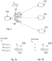
- Fig. 2 is a schematic illustration of how the server 101 communicates with each client device 151, 152, 153 sending timing information T sx in messages, here in the form of packets 10 sent at a specific time instance.
- FIGs. 3a and 3b an example of such message data packet 10a containing timing information T sx according to an embodiment of the inventive concept is given, which is sent at a specific time instance s when the local clock of the server 101 provides a time stamp t s to each client device 151, 152, 153 (note that specific time instance is denoted s, and client device is denoted x in timing information T sx ).
- Fig. 3a and 3b an example of such message data packet 10a containing timing information T sx according to an embodiment of the inventive concept is given, which is sent at a specific time instance s when the local clock of the server 101 provides a time stamp t s to each client device 151, 152, 153 (note that specific time instance is denoted s,
- the timing information T sx comprises a time difference ⁇ (t s -t x ) and the time stamp t s , where t x is a respective per client device time stamp received in the server. Note that for each timing packet 10a, the timing information is different.
- Each packet 10a contains a portion 11a which comprises per client timing information and payload, e.g. the same media content to be displayed by all client devices at a predefined presentation time (not shown). Note in the first mode, that portion 11a of the packet 10a is different for each client device due to the different timing information.
- time differences estimated in the respective client devices are sent to the server in addition to the client device time stamps t x , which is advantageous if the local clocks of the server and the client devices need to be mutually synchronized, or simply as information to the server regarding time differences associated with each client device.
- the second mode according to an embodiment of the present inventive concept is illustrated and here the timing information T sx comprises only the time stamp t s .
- the timing information is identical for all clients.
- Each packet 10b contains a portion 11b which comprises per client timing information and payload, e.g. media content to be displayed. Note that for the second mode, that portion 11b is identical for all client devices.
- the distribution system further comprises a control device for handling synchronization of playout time of media content at the client devices, which here is embodied by a separate control server 101a, arranged in communication with server 101b for data streaming and the client devices 151, 152, 153 either arranged separately from the server 101, or integrated in the server 101 as illustrated with the dashed box (server 101) in Fig. 1 .
- the control device 101a is preferably a software module and/or data-transport module comprising a processor, and memory device, or when implemented in an external device comprising a processor and memory device.
- a first mode with selective two-way time transfer according to the invention is (individually) employed for a connected client device, which is subsequently followed by step S420, in which a second mode is activated.
- the playout of the live media content DS to all client devices connected to that server are synchronized with respect to the local clock of the server 101 by means of providing the local clock signal and transferring a time stamp of the same to the (each) client device which is connected to the server, receiving in the server a local clock signal of the client device, estimating in the server a time difference based on the local clock signal of the server and the received clock signal from the client device, transferring the estimated time difference between the server and the client device to the client device, and adjusting the local clock signal of the client device based on the estimated time difference.
- This procedure may be repeated until the time difference between the client device and the server reaches an acceptable threshold value, which represents a quality factor Q of the synchronization of the respective client device clock with respect to the server, or within a predetermined time period T before continuing to step S420.
- step S420 the use of two-way time transfer may be made selective by the employing, i.e. returning to step S410, the two-way time transfer (first mode) with a predetermined frequency for rate.
- a predetermined frequency for rate examples of typical applicable frequency is 10 times per second.
- the first mode is employed during a predetermined time interval T, which typically can be 100 ms each second.
- full two-way time transfer is employed to adjust the device clock.
- this will be relevant for all devices and to preserve BW/processing the lowest ABR level may be employed.
- only newly connected devices will initially use full two-way time transfer.
- the two-way time transfer is selectively used (or sent) entering the first mode, step S410, with low frequency f to reduce the number of per client device specific messages and to maintain the client device clock adjusted, or entering and exiting the selective two-way time transfer (first mode) based on other factors as illustrated with reference to Fig. 5 .
- the method in between employing the two-way time transfer selectively (first mode), when in a step S415, either a time period T or optionally based on the measured quality factor Q, which may be directly derived from the estimated time difference between the client device- and the server clocks, the method enters a step S420 in which the server only sends time stamps of its own clock (not the time difference between its clock and the respective client device clock), meaning that all client devices receive the same message.
- This message comprising a time stamp of the local clock of the server, can then be used to determine in a step S422 (see Fig. 7 ) unidirectional delay from server to device and the RTT by simply multiplying the unidirectional delay from server to device with 2 when symmetric delay is assumed.
- the method may comprise an optional step of providing ABR adjustments, or other method, e.g. selective retransmission, to reduce the traffic to avoid congestion, based on the determined unidirectional delay (or RTT). If in the second mode, it is determined that the unidirectional delay (or RTT) increases above or below a predetermined range or if increase/decrease of the unidirectional delay (or RTT) is very rapid, the ABR is adjusted accordingly.
- the estimation of the server to device delay will be accurate since both the server- and device clocks are sufficiently synchronized and the difference between the received clock and the local clock estimates the unidirectional delay.
- step S410 based on the preset frequency f for employing the first mode or alternatively a predetermined time interval I or a measured or estimated performance factor like RTT, step S410 is subsequently employed.
- the shown embodiment of the method comprises a step S412 which may be positioned between step S410 and step S415.
- the method then further comprises estimating at least one of the predetermined time interval I, and the predetermined frequency f based on the estimated time difference which is available in the first mode when two-way time transfer is selectively provided.
- the client devices may correct the erroneously received information amongst other techniques by retransmission techniques, which enable the erroneously received information to be retransmitted to the receiver, for example, by using automatic retransmission request (ARQ).
- ARQ automatic retransmission request
- the RTT is estimated based on the unidirectional delay in the system to determine timer settings for retransmission of NACKs to recover from lost NACKs or retransmitted data, typically timers are set to 4 X RTT to balance out unnecessary retransmissions of NACK and data in relation to delays in the system.
- timers are set to 4 X RTT to balance out unnecessary retransmissions of NACK and data in relation to delays in the system.
Landscapes
- Engineering & Computer Science (AREA)
- Signal Processing (AREA)
- Multimedia (AREA)
- Computer Networks & Wireless Communication (AREA)
- Databases & Information Systems (AREA)
- Data Exchanges In Wide-Area Networks (AREA)
- Two-Way Televisions, Distribution Of Moving Picture Or The Like (AREA)
Claims (12)
- Verfahren in einem Netzwerksystem, das zur Knoten-zu-Knoten-Zeitübertragung geeignet ist, um eine jeweilige lokale Uhr eines Ursprungsservers und mindestens eines Client-Geräts oder eines anderen Servers mittels Zwei-Wege-Zeitübertragung zu synchronisieren, wobei die Zwei-Wege-Zeitübertragung die Bereitstellung eines lokalen Taktsignals auf dem Ursprungsserver umfasst, und
für jedes der mindestens einen Client-Geräte oder der anderen Server, die mit dem Ursprungsserver verbunden sind:Empfangen, am Ursprungsserver, eines lokalen Taktsignals des mindestens einen Client-Geräts oder anderen Servers;Schätzen einer Zeitdifferenz am Ursprungsserver basierend auf dem lokalen Taktsignal des Ursprungsservers und dem von dem mindestens einen Client-Gerät oder anderen Server empfangenen Taktsignal;Übertragen des lokalen Taktsignals des Ursprungsservers und der geschätzten Zeitdifferenz am Ursprungsserver an das mindestens eine Client-Gerät oder den anderen Server;Schätzen einer Zeitdifferenz an dem mindestens einen Client-Gerät oder anderen Server basierend auf einem lokalen Taktsignal des mindestens einen Client-Geräts oder anderen Servers und dem empfangenen Taktsignal des Ursprungsservers; undAnpassen des lokalen Taktsignals des mindestens einen Client-Geräts oder anderen Servers basierend auf der empfangenen geschätzten Zeitdifferenz am Ursprungsserver, der geschätzten Zeitdifferenz an dem mindestens einen Client-Gerät oder anderen Server, und dem lokalen Taktsignal des mindestens ein Client-Geräts oder anderen Servers, wobei das Verfahren dadurch gekennzeichnet ist, dass es einen ersten Modus umfasst, in dem die Zwei-Wege-Zeitübertragung selektiv verwendet wird, und ferner die Verwendung eines zweiten Modus umfasst, in dem nur das lokale Taktsignal des Ursprungsservers und das lokale Taktsignal des mindestens einen Client-Geräts oder anderen Servers zwischen dem Ursprungsserver und dem mindestens einen Client-Gerät oder anderen Server ausgetauscht werden. - Verfahren nach Anspruch 1, wobei in dem ersten Modus eine Zwei-Wege-Zeitübertragung verwendet wird gemäß mindestens einem von:während vorbestimmter Zeitintervalle T, undmit einer vorgegebenen Frequenz f oder Rate R.
- Verfahren nach Anspruch 2, ferner umfassend, in dem ersten Modus, Schätzen mindestens eines von dem vorgegebenen Zeitintervall T, der vorgegebenen Frequenz f und der Rate R basierend auf mindestens einem von der geschätzten Zeitdifferenz am Ursprungsserver, und der geschätzten Zeitdifferenz an dem mindestens einem Client-Gerät oder anderen Server.
- Verfahren nach einem der vorhergehenden Ansprüche, wobei der erste Modus verwendet wird, bis ein vorgegebener Schwellenwert der geschätzten Zeitdifferenz am Ursprungsserver, oder dem mindestens einem Client-Gerät oder dem anderen Server, erreicht wird.
- Verfahren nach einem der vorhergehenden Ansprüche, ferner umfassend Bestimmen einer unidirektionalen Verzögerung und/oder Umlaufzeit, RTT, zwischen dem Ursprungsserver und dem mindestens einen Client-Gerät oder anderen Server basierend auf dem lokalen Taktsignal des Ursprungsservers und dem lokalen Taktsignal des mindestens einen Client-Geräts oder anderen Servers.
- Verfahren nach Anspruch 5, ferner umfassend Bereitstellen von ABR-Anpassungen basierend auf der bestimmten unidirektionalen Verzögerung oder RTT.
- Verfahren nach einem der vorhergehenden Ansprüche, wobei der zweite Modus basierend auf mindestens einem von aktiviert wird: das vorgegebene Zeitintervall T ist verstrichen, und der vorgegebene Schwellenwert der geschätzten Zeitdifferenz an dem mindestens einen Client-Gerät oder anderen Server in dem ersten Modus wurde erreicht.
- Verfahren nach einem der vorhergehenden Ansprüche, wobei der erste Modus basierend auf einem von einer vorgegebenen Frequenz, einem Zeitgeber, oder der geschätzten Zeitdifferenz an dem mindestens einen Client-Gerät oder anderen Server aktiviert wird.
- Verfahren nach einem der vorhergehenden Ansprüche, ferner umfassend einen Initiierungsmodus, der eine vollständige Zwei-Wege-Zeitübertragung verwendet, wenn der Ursprungsserver zum ersten Mal mit einem neuen Client-Gerät oder einem anderen Server verbunden wird.
- Verfahren nach einem der Ansprüche 5-6, wobei die unidirektionale Verzögerung in der Richtung des Inhaltsstroms bestimmt wird.
- Knoten für ein Kommunikationssystem, das für eine Knoten-zu-Knoten-Kommunikation ausgelegt ist, wobei der Knoten umfasst:
einen Speicher, der computerlesbare Anweisungen speichert, und einen Prozessor, der dazu ausgebildet ist, die computerlesbaren Anweisungen für ein Verfahren nach einem der Ansprüche 1 bis 10 auszuführen. - Nichtflüchtiges computerlesbares Speichermedium, das computerlesbare Anweisungen speichert, die von einem Prozessor ausgeführt werden können, um den Prozessor zu veranlassen, das Verfahren nach einem der Ansprüche 1 bis 10 auszuführen.
Applications Claiming Priority (2)
| Application Number | Priority Date | Filing Date | Title |
|---|---|---|---|
| SE1651288 | 2016-09-30 | ||
| PCT/EP2017/074806 WO2018060441A1 (en) | 2016-09-30 | 2017-09-29 | Time synchronization in a live content distribution system |
Publications (3)
| Publication Number | Publication Date |
|---|---|
| EP3520253A1 EP3520253A1 (de) | 2019-08-07 |
| EP3520253C0 EP3520253C0 (de) | 2023-11-01 |
| EP3520253B1 true EP3520253B1 (de) | 2023-11-01 |
Family
ID=60001918
Family Applications (1)
| Application Number | Title | Priority Date | Filing Date |
|---|---|---|---|
| EP17777887.5A Active EP3520253B1 (de) | 2016-09-30 | 2017-09-29 | Zeitsynchronisation in einem live-inhaltsverteilungssystem |
Country Status (4)
| Country | Link |
|---|---|
| US (2) | US10972775B2 (de) |
| EP (1) | EP3520253B1 (de) |
| CN (2) | CN109716683B (de) |
| WO (1) | WO2018060441A1 (de) |
Families Citing this family (2)
| Publication number | Priority date | Publication date | Assignee | Title |
|---|---|---|---|---|
| JP7694267B2 (ja) * | 2021-09-01 | 2025-06-18 | 日本電気株式会社 | 通信制御装置、通信制御方法、及び通信制御プログラム |
| JP2024107722A (ja) * | 2023-01-30 | 2024-08-09 | トヨタ自動車株式会社 | 情報処理装置及び情報処理方法 |
Family Cites Families (21)
| Publication number | Priority date | Publication date | Assignee | Title |
|---|---|---|---|---|
| US6625176B1 (en) * | 1999-04-12 | 2003-09-23 | International Business Machines Corporation | Method and apparatus for adjustment of time delays in synchronous clocked bus systems |
| US7191355B1 (en) | 2002-02-19 | 2007-03-13 | Nortel Networks Limited | Clock synchronization backup mechanism for circuit emulation service |
| US20040223515A1 (en) * | 2003-01-14 | 2004-11-11 | Rygielski Ronald E. | Method and apparatus for the synchronization of a system time of a communications network with a clock reference |
| US7535931B1 (en) * | 2003-07-14 | 2009-05-19 | Symmetricom, Inc. | Two-way timing protocol |
| CN100370805C (zh) * | 2005-05-23 | 2008-02-20 | 华为技术有限公司 | 广播电视业务的接收端与源端同步的实现方法及系统 |
| CN101155132B (zh) * | 2006-09-27 | 2012-07-04 | 中兴通讯股份有限公司 | 一种间接实时流量控制系统及其方法 |
| CN101202701B (zh) * | 2006-12-12 | 2012-09-05 | 中兴通讯股份有限公司 | 分组网络中为汇聚的可用比特率业务分配带宽的方法 |
| EP1990938A1 (de) * | 2007-05-10 | 2008-11-12 | Deutsche Thomson OHG | Verfahren zum Synchronisieren einer Uhr einer Netzwerkkomponente mit der Uhr einer anderen Netzwerkkomponente sowie Netzwerkkomponente |
| CN101394324B (zh) * | 2008-09-12 | 2011-05-18 | 武汉理工大学 | 一种适用于网络控制系统的混合式单向时延估计方法 |
| US8363681B2 (en) * | 2008-10-16 | 2013-01-29 | Entropic Communications, Inc. | Method and apparatus for using ranging measurements in a multimedia home network |
| WO2011025746A1 (en) * | 2009-08-25 | 2011-03-03 | Semtech Corporation | Measurement and adjustment of real-time values according to residence time in networking equipment without access to real time |
| GB201003206D0 (en) * | 2010-02-25 | 2010-04-14 | Skype Ltd | Method of estimating congestion |
| CN101895384A (zh) * | 2010-07-07 | 2010-11-24 | 中兴通讯股份有限公司 | 一种实现边界时钟的方法和装置 |
| US9106645B1 (en) * | 2011-01-26 | 2015-08-11 | Symantec Corporation | Automatic reset for time-based credentials on a mobile device |
| EP2541815B1 (de) | 2011-06-28 | 2013-12-18 | Alcatel Lucent | Taktsynchronisationsnetzwerk |
| CN102790913B (zh) | 2012-07-03 | 2016-11-16 | 深圳市时代经纬科技有限公司 | 一种基于3g网络音视频传输方法 |
| EP2993816A1 (de) * | 2014-09-03 | 2016-03-09 | Thomson Licensing | Verfahren zum Austausch von Nachrichten in einem Netzwerksystem und Vorrichtung zur Verwendung in dem Verfahren entsprechend der Erfindung |
| US9537592B2 (en) * | 2014-10-29 | 2017-01-03 | Meggitt Training Systems, Inc. | Systems and methods for synching a host computer with a variety of external devices |
| CN107005961A (zh) | 2014-12-08 | 2017-08-01 | 耐克斯特纳威公司 | 用于选择性地接收和处理rf信标处的rf信号的系统和方法 |
| CN104660361A (zh) * | 2015-02-11 | 2015-05-27 | 杨德朝 | 分布式网络授时的滤波方法 |
| EP3135923A1 (de) | 2015-08-18 | 2017-03-01 | Sulzer Management AG | Ausstosskopf für eine vertikale pumpe und vertikale pumpe |
-
2017
- 2017-09-29 US US16/338,131 patent/US10972775B2/en active Active
- 2017-09-29 EP EP17777887.5A patent/EP3520253B1/de active Active
- 2017-09-29 WO PCT/EP2017/074806 patent/WO2018060441A1/en not_active Ceased
- 2017-09-29 CN CN201780057191.7A patent/CN109716683B/zh active Active
- 2017-09-29 CN CN202011575808.4A patent/CN112866758B/zh active Active
-
2020
- 2020-12-22 US US17/130,772 patent/US11659215B2/en active Active
Also Published As
| Publication number | Publication date |
|---|---|
| US20210112294A1 (en) | 2021-04-15 |
| CN109716683B (zh) | 2021-03-19 |
| WO2018060441A1 (en) | 2018-04-05 |
| US20190273957A1 (en) | 2019-09-05 |
| CN109716683A (zh) | 2019-05-03 |
| US10972775B2 (en) | 2021-04-06 |
| US11659215B2 (en) | 2023-05-23 |
| EP3520253C0 (de) | 2023-11-01 |
| EP3520253A1 (de) | 2019-08-07 |
| CN112866758B (zh) | 2024-01-05 |
| CN112866758A (zh) | 2021-05-28 |
Similar Documents
| Publication | Publication Date | Title |
|---|---|---|
| US11611498B2 (en) | Round-trip time evaluation system, method, and apparatus | |
| EP2374249B1 (de) | Datenratensteuermechanismus | |
| US9577935B2 (en) | Unified congestion control for real-time media support | |
| US9143418B2 (en) | Network transmission capacity measurement | |
| US11102273B2 (en) | Uplink performance management | |
| JP5824347B2 (ja) | 時刻同期装置及び方法 | |
| EP3560152B1 (de) | Bestimmung der bandbreite einer kommunikationsverbindung | |
| US20110205895A1 (en) | Method of estimating congestion | |
| US12308949B2 (en) | Link profiling for asymmetric delay compensation | |
| JP2004007361A (ja) | データ送信制御方法及びこの方法のプログラム並びにこれを用いるデータ送信装置 | |
| US11659215B2 (en) | Time synchronization in a live content distribution system | |
| JP2009017143A (ja) | 受信端末及び受信方法 | |
| WO2012071851A1 (zh) | 根据网络抖动调整bfd发送间隔的方法及装置 | |
| US11973683B2 (en) | Communication nodes and methods performed therein for handling packets in an information centric network | |
| EP2561644B1 (de) | Beurteilung einer verfügbaren Pfadbitrate auf Grundlage einer Quittungspfadauswahl | |
| CN118802081B (zh) | 数据重传方法、装置、设备、存储介质以及程序产品 | |
| US11445341B2 (en) | Dynamic weighing device | |
| EP3907943B1 (de) | Schätzung einer umlaufzeit | |
| KR101665924B1 (ko) | NTP(network time protocol) 타임 오프셋을 이용한 주파수 오차 추정 시스템 | |
| JP6717209B2 (ja) | パケット列送・受信装置、ネットワーク状態推定システムおよび制御方法 | |
| KR20120119094A (ko) | 병목지점 검출 방법 및 장치 |
Legal Events
| Date | Code | Title | Description |
|---|---|---|---|
| STAA | Information on the status of an ep patent application or granted ep patent |
Free format text: STATUS: UNKNOWN |
|
| STAA | Information on the status of an ep patent application or granted ep patent |
Free format text: STATUS: THE INTERNATIONAL PUBLICATION HAS BEEN MADE |
|
| PUAI | Public reference made under article 153(3) epc to a published international application that has entered the european phase |
Free format text: ORIGINAL CODE: 0009012 |
|
| STAA | Information on the status of an ep patent application or granted ep patent |
Free format text: STATUS: REQUEST FOR EXAMINATION WAS MADE |
|
| 17P | Request for examination filed |
Effective date: 20190418 |
|
| AK | Designated contracting states |
Kind code of ref document: A1 Designated state(s): AL AT BE BG CH CY CZ DE DK EE ES FI FR GB GR HR HU IE IS IT LI LT LU LV MC MK MT NL NO PL PT RO RS SE SI SK SM TR |
|
| AX | Request for extension of the european patent |
Extension state: BA ME |
|
| DAV | Request for validation of the european patent (deleted) | ||
| DAX | Request for extension of the european patent (deleted) | ||
| RAP1 | Party data changed (applicant data changed or rights of an application transferred) |
Owner name: NET INSIGHT AB |
|
| STAA | Information on the status of an ep patent application or granted ep patent |
Free format text: STATUS: EXAMINATION IS IN PROGRESS |
|
| 17Q | First examination report despatched |
Effective date: 20210922 |
|
| GRAP | Despatch of communication of intention to grant a patent |
Free format text: ORIGINAL CODE: EPIDOSNIGR1 |
|
| STAA | Information on the status of an ep patent application or granted ep patent |
Free format text: STATUS: GRANT OF PATENT IS INTENDED |
|
| INTG | Intention to grant announced |
Effective date: 20230203 |
|
| GRAJ | Information related to disapproval of communication of intention to grant by the applicant or resumption of examination proceedings by the epo deleted |
Free format text: ORIGINAL CODE: EPIDOSDIGR1 |
|
| STAA | Information on the status of an ep patent application or granted ep patent |
Free format text: STATUS: EXAMINATION IS IN PROGRESS |
|
| GRAP | Despatch of communication of intention to grant a patent |
Free format text: ORIGINAL CODE: EPIDOSNIGR1 |
|
| STAA | Information on the status of an ep patent application or granted ep patent |
Free format text: STATUS: GRANT OF PATENT IS INTENDED |
|
| INTC | Intention to grant announced (deleted) | ||
| INTG | Intention to grant announced |
Effective date: 20230615 |
|
| GRAS | Grant fee paid |
Free format text: ORIGINAL CODE: EPIDOSNIGR3 |
|
| GRAA | (expected) grant |
Free format text: ORIGINAL CODE: 0009210 |
|
| STAA | Information on the status of an ep patent application or granted ep patent |
Free format text: STATUS: THE PATENT HAS BEEN GRANTED |
|
| AK | Designated contracting states |
Kind code of ref document: B1 Designated state(s): AL AT BE BG CH CY CZ DE DK EE ES FI FR GB GR HR HU IE IS IT LI LT LU LV MC MK MT NL NO PL PT RO RS SE SI SK SM TR |
|
| REG | Reference to a national code |
Ref country code: GB Ref legal event code: FG4D |
|
| REG | Reference to a national code |
Ref country code: CH Ref legal event code: EP |
|
| REG | Reference to a national code |
Ref country code: IE Ref legal event code: FG4D |
|
| REG | Reference to a national code |
Ref country code: DE Ref legal event code: R096 Ref document number: 602017076027 Country of ref document: DE |
|
| U01 | Request for unitary effect filed |
Effective date: 20231101 |
|
| U07 | Unitary effect registered |
Designated state(s): AT BE BG DE DK EE FI FR IT LT LU LV MT NL PT SE SI Effective date: 20231107 |
|
| PG25 | Lapsed in a contracting state [announced via postgrant information from national office to epo] |
Ref country code: GR Free format text: LAPSE BECAUSE OF FAILURE TO SUBMIT A TRANSLATION OF THE DESCRIPTION OR TO PAY THE FEE WITHIN THE PRESCRIBED TIME-LIMIT Effective date: 20240202 |
|
| PG25 | Lapsed in a contracting state [announced via postgrant information from national office to epo] |
Ref country code: IS Free format text: LAPSE BECAUSE OF FAILURE TO SUBMIT A TRANSLATION OF THE DESCRIPTION OR TO PAY THE FEE WITHIN THE PRESCRIBED TIME-LIMIT Effective date: 20240301 |
|
| PG25 | Lapsed in a contracting state [announced via postgrant information from national office to epo] |
Ref country code: ES Free format text: LAPSE BECAUSE OF FAILURE TO SUBMIT A TRANSLATION OF THE DESCRIPTION OR TO PAY THE FEE WITHIN THE PRESCRIBED TIME-LIMIT Effective date: 20231101 |
|
| PG25 | Lapsed in a contracting state [announced via postgrant information from national office to epo] |
Ref country code: IS Free format text: LAPSE BECAUSE OF FAILURE TO SUBMIT A TRANSLATION OF THE DESCRIPTION OR TO PAY THE FEE WITHIN THE PRESCRIBED TIME-LIMIT Effective date: 20240301 Ref country code: GR Free format text: LAPSE BECAUSE OF FAILURE TO SUBMIT A TRANSLATION OF THE DESCRIPTION OR TO PAY THE FEE WITHIN THE PRESCRIBED TIME-LIMIT Effective date: 20240202 Ref country code: ES Free format text: LAPSE BECAUSE OF FAILURE TO SUBMIT A TRANSLATION OF THE DESCRIPTION OR TO PAY THE FEE WITHIN THE PRESCRIBED TIME-LIMIT Effective date: 20231101 |
|
| PG25 | Lapsed in a contracting state [announced via postgrant information from national office to epo] |
Ref country code: RS Free format text: LAPSE BECAUSE OF FAILURE TO SUBMIT A TRANSLATION OF THE DESCRIPTION OR TO PAY THE FEE WITHIN THE PRESCRIBED TIME-LIMIT Effective date: 20231101 Ref country code: PL Free format text: LAPSE BECAUSE OF FAILURE TO SUBMIT A TRANSLATION OF THE DESCRIPTION OR TO PAY THE FEE WITHIN THE PRESCRIBED TIME-LIMIT Effective date: 20231101 Ref country code: NO Free format text: LAPSE BECAUSE OF FAILURE TO SUBMIT A TRANSLATION OF THE DESCRIPTION OR TO PAY THE FEE WITHIN THE PRESCRIBED TIME-LIMIT Effective date: 20240201 Ref country code: HR Free format text: LAPSE BECAUSE OF FAILURE TO SUBMIT A TRANSLATION OF THE DESCRIPTION OR TO PAY THE FEE WITHIN THE PRESCRIBED TIME-LIMIT Effective date: 20231101 |
|
| PG25 | Lapsed in a contracting state [announced via postgrant information from national office to epo] |
Ref country code: CZ Free format text: LAPSE BECAUSE OF FAILURE TO SUBMIT A TRANSLATION OF THE DESCRIPTION OR TO PAY THE FEE WITHIN THE PRESCRIBED TIME-LIMIT Effective date: 20231101 |
|
| PG25 | Lapsed in a contracting state [announced via postgrant information from national office to epo] |
Ref country code: SK Free format text: LAPSE BECAUSE OF FAILURE TO SUBMIT A TRANSLATION OF THE DESCRIPTION OR TO PAY THE FEE WITHIN THE PRESCRIBED TIME-LIMIT Effective date: 20231101 |
|
| PG25 | Lapsed in a contracting state [announced via postgrant information from national office to epo] |
Ref country code: SM Free format text: LAPSE BECAUSE OF FAILURE TO SUBMIT A TRANSLATION OF THE DESCRIPTION OR TO PAY THE FEE WITHIN THE PRESCRIBED TIME-LIMIT Effective date: 20231101 Ref country code: SK Free format text: LAPSE BECAUSE OF FAILURE TO SUBMIT A TRANSLATION OF THE DESCRIPTION OR TO PAY THE FEE WITHIN THE PRESCRIBED TIME-LIMIT Effective date: 20231101 Ref country code: CZ Free format text: LAPSE BECAUSE OF FAILURE TO SUBMIT A TRANSLATION OF THE DESCRIPTION OR TO PAY THE FEE WITHIN THE PRESCRIBED TIME-LIMIT Effective date: 20231101 |
|
| REG | Reference to a national code |
Ref country code: DE Ref legal event code: R097 Ref document number: 602017076027 Country of ref document: DE |
|
| PLBE | No opposition filed within time limit |
Free format text: ORIGINAL CODE: 0009261 |
|
| STAA | Information on the status of an ep patent application or granted ep patent |
Free format text: STATUS: NO OPPOSITION FILED WITHIN TIME LIMIT |
|
| U20 | Renewal fee for the european patent with unitary effect paid |
Year of fee payment: 8 Effective date: 20240814 |
|
| 26N | No opposition filed |
Effective date: 20240802 |
|
| PG25 | Lapsed in a contracting state [announced via postgrant information from national office to epo] |
Ref country code: MC Free format text: LAPSE BECAUSE OF FAILURE TO SUBMIT A TRANSLATION OF THE DESCRIPTION OR TO PAY THE FEE WITHIN THE PRESCRIBED TIME-LIMIT Effective date: 20231101 |
|
| REG | Reference to a national code |
Ref country code: CH Ref legal event code: PL |
|
| PG25 | Lapsed in a contracting state [announced via postgrant information from national office to epo] |
Ref country code: CH Free format text: LAPSE BECAUSE OF NON-PAYMENT OF DUE FEES Effective date: 20240930 |
|
| PG25 | Lapsed in a contracting state [announced via postgrant information from national office to epo] |
Ref country code: IE Free format text: LAPSE BECAUSE OF NON-PAYMENT OF DUE FEES Effective date: 20240929 |
|
| U20 | Renewal fee for the european patent with unitary effect paid |
Year of fee payment: 9 Effective date: 20250815 |
|
| PGFP | Annual fee paid to national office [announced via postgrant information from national office to epo] |
Ref country code: GB Payment date: 20250813 Year of fee payment: 9 |
|
| PG25 | Lapsed in a contracting state [announced via postgrant information from national office to epo] |
Ref country code: RO Free format text: LAPSE BECAUSE OF FAILURE TO SUBMIT A TRANSLATION OF THE DESCRIPTION OR TO PAY THE FEE WITHIN THE PRESCRIBED TIME-LIMIT Effective date: 20231101 |
|
| PG25 | Lapsed in a contracting state [announced via postgrant information from national office to epo] |
Ref country code: CY Free format text: LAPSE BECAUSE OF FAILURE TO SUBMIT A TRANSLATION OF THE DESCRIPTION OR TO PAY THE FEE WITHIN THE PRESCRIBED TIME-LIMIT; INVALID AB INITIO Effective date: 20170929 |
|
| PG25 | Lapsed in a contracting state [announced via postgrant information from national office to epo] |
Ref country code: HU Free format text: LAPSE BECAUSE OF FAILURE TO SUBMIT A TRANSLATION OF THE DESCRIPTION OR TO PAY THE FEE WITHIN THE PRESCRIBED TIME-LIMIT; INVALID AB INITIO Effective date: 20170929 |
|
| PG25 | Lapsed in a contracting state [announced via postgrant information from national office to epo] |
Ref country code: TR Free format text: LAPSE BECAUSE OF FAILURE TO SUBMIT A TRANSLATION OF THE DESCRIPTION OR TO PAY THE FEE WITHIN THE PRESCRIBED TIME-LIMIT Effective date: 20231101 |