EP3519996B1 - Process for designing a virtual sensor, corresponding virtual sensor, system, and computer-program products - Google Patents
Process for designing a virtual sensor, corresponding virtual sensor, system, and computer-program products Download PDFInfo
- Publication number
- EP3519996B1 EP3519996B1 EP17785017.9A EP17785017A EP3519996B1 EP 3519996 B1 EP3519996 B1 EP 3519996B1 EP 17785017 A EP17785017 A EP 17785017A EP 3519996 B1 EP3519996 B1 EP 3519996B1
- Authority
- EP
- European Patent Office
- Prior art keywords
- variable
- function
- interest
- virtual sensor
- lipschitz
- Prior art date
- Legal status (The legal status is an assumption and is not a legal conclusion. Google has not performed a legal analysis and makes no representation as to the accuracy of the status listed.)
- Active
Links
Images



Classifications
-
- F—MECHANICAL ENGINEERING; LIGHTING; HEATING; WEAPONS; BLASTING
- F01—MACHINES OR ENGINES IN GENERAL; ENGINE PLANTS IN GENERAL; STEAM ENGINES
- F01N—GAS-FLOW SILENCERS OR EXHAUST APPARATUS FOR MACHINES OR ENGINES IN GENERAL; GAS-FLOW SILENCERS OR EXHAUST APPARATUS FOR INTERNAL-COMBUSTION ENGINES
- F01N9/00—Electrical control of exhaust gas treating apparatus
- F01N9/005—Electrical control of exhaust gas treating apparatus using models instead of sensors to determine operating characteristics of exhaust systems, e.g. calculating catalyst temperature instead of measuring it directly
-
- F—MECHANICAL ENGINEERING; LIGHTING; HEATING; WEAPONS; BLASTING
- F02—COMBUSTION ENGINES; HOT-GAS OR COMBUSTION-PRODUCT ENGINE PLANTS
- F02D—CONTROLLING COMBUSTION ENGINES
- F02D41/00—Electrical control of supply of combustible mixture or its constituents
- F02D41/02—Circuit arrangements for generating control signals
- F02D41/14—Introducing closed-loop corrections
- F02D41/1438—Introducing closed-loop corrections using means for determining characteristics of the combustion gases; Sensors therefor
- F02D41/1444—Introducing closed-loop corrections using means for determining characteristics of the combustion gases; Sensors therefor characterised by the characteristics of the combustion gases
- F02D41/146—Introducing closed-loop corrections using means for determining characteristics of the combustion gases; Sensors therefor characterised by the characteristics of the combustion gases the characteristics being an NOx content or concentration
- F02D41/1461—Introducing closed-loop corrections using means for determining characteristics of the combustion gases; Sensors therefor characterised by the characteristics of the combustion gases the characteristics being an NOx content or concentration of the exhaust gases emitted by the engine
- F02D41/1462—Introducing closed-loop corrections using means for determining characteristics of the combustion gases; Sensors therefor characterised by the characteristics of the combustion gases the characteristics being an NOx content or concentration of the exhaust gases emitted by the engine with determination means using an estimation
-
- F—MECHANICAL ENGINEERING; LIGHTING; HEATING; WEAPONS; BLASTING
- F01—MACHINES OR ENGINES IN GENERAL; ENGINE PLANTS IN GENERAL; STEAM ENGINES
- F01N—GAS-FLOW SILENCERS OR EXHAUST APPARATUS FOR MACHINES OR ENGINES IN GENERAL; GAS-FLOW SILENCERS OR EXHAUST APPARATUS FOR INTERNAL-COMBUSTION ENGINES
- F01N11/00—Monitoring or diagnostic devices for exhaust-gas treatment apparatus
- F01N11/007—Monitoring or diagnostic devices for exhaust-gas treatment apparatus the diagnostic devices measuring oxygen or air concentration downstream of the exhaust apparatus
-
- F—MECHANICAL ENGINEERING; LIGHTING; HEATING; WEAPONS; BLASTING
- F02—COMBUSTION ENGINES; HOT-GAS OR COMBUSTION-PRODUCT ENGINE PLANTS
- F02D—CONTROLLING COMBUSTION ENGINES
- F02D41/00—Electrical control of supply of combustible mixture or its constituents
- F02D41/02—Circuit arrangements for generating control signals
- F02D41/021—Introducing corrections for particular conditions exterior to the engine
-
- G—PHYSICS
- G06—COMPUTING OR CALCULATING; COUNTING
- G06F—ELECTRIC DIGITAL DATA PROCESSING
- G06F30/00—Computer-aided design [CAD]
- G06F30/10—Geometric CAD
- G06F30/15—Vehicle, aircraft or watercraft design
-
- G—PHYSICS
- G06—COMPUTING OR CALCULATING; COUNTING
- G06F—ELECTRIC DIGITAL DATA PROCESSING
- G06F30/00—Computer-aided design [CAD]
- G06F30/30—Circuit design
-
- F—MECHANICAL ENGINEERING; LIGHTING; HEATING; WEAPONS; BLASTING
- F01—MACHINES OR ENGINES IN GENERAL; ENGINE PLANTS IN GENERAL; STEAM ENGINES
- F01N—GAS-FLOW SILENCERS OR EXHAUST APPARATUS FOR MACHINES OR ENGINES IN GENERAL; GAS-FLOW SILENCERS OR EXHAUST APPARATUS FOR INTERNAL-COMBUSTION ENGINES
- F01N2560/00—Exhaust systems with means for detecting or measuring exhaust gas components or characteristics
- F01N2560/02—Exhaust systems with means for detecting or measuring exhaust gas components or characteristics the means being an exhaust gas sensor
- F01N2560/026—Exhaust systems with means for detecting or measuring exhaust gas components or characteristics the means being an exhaust gas sensor for measuring or detecting NOx
-
- F—MECHANICAL ENGINEERING; LIGHTING; HEATING; WEAPONS; BLASTING
- F01—MACHINES OR ENGINES IN GENERAL; ENGINE PLANTS IN GENERAL; STEAM ENGINES
- F01N—GAS-FLOW SILENCERS OR EXHAUST APPARATUS FOR MACHINES OR ENGINES IN GENERAL; GAS-FLOW SILENCERS OR EXHAUST APPARATUS FOR INTERNAL-COMBUSTION ENGINES
- F01N2900/00—Details of electrical control or of the monitoring of the exhaust gas treating apparatus
- F01N2900/06—Parameters used for exhaust control or diagnosing
- F01N2900/08—Parameters used for exhaust control or diagnosing said parameters being related to the engine
-
- F—MECHANICAL ENGINEERING; LIGHTING; HEATING; WEAPONS; BLASTING
- F02—COMBUSTION ENGINES; HOT-GAS OR COMBUSTION-PRODUCT ENGINE PLANTS
- F02D—CONTROLLING COMBUSTION ENGINES
- F02D2200/00—Input parameters for engine control
- F02D2200/02—Input parameters for engine control the parameters being related to the engine
- F02D2200/021—Engine temperature
- F02D2200/022—Estimation of engine temperature
-
- F—MECHANICAL ENGINEERING; LIGHTING; HEATING; WEAPONS; BLASTING
- F02—COMBUSTION ENGINES; HOT-GAS OR COMBUSTION-PRODUCT ENGINE PLANTS
- F02D—CONTROLLING COMBUSTION ENGINES
- F02D2200/00—Input parameters for engine control
- F02D2200/02—Input parameters for engine control the parameters being related to the engine
- F02D2200/024—Fluid pressure of lubricating oil or working fluid
-
- F—MECHANICAL ENGINEERING; LIGHTING; HEATING; WEAPONS; BLASTING
- F02—COMBUSTION ENGINES; HOT-GAS OR COMBUSTION-PRODUCT ENGINE PLANTS
- F02D—CONTROLLING COMBUSTION ENGINES
- F02D2200/00—Input parameters for engine control
- F02D2200/02—Input parameters for engine control the parameters being related to the engine
- F02D2200/04—Engine intake system parameters
- F02D2200/0406—Intake manifold pressure
- F02D2200/0408—Estimation of intake manifold pressure
-
- F—MECHANICAL ENGINEERING; LIGHTING; HEATING; WEAPONS; BLASTING
- F02—COMBUSTION ENGINES; HOT-GAS OR COMBUSTION-PRODUCT ENGINE PLANTS
- F02D—CONTROLLING COMBUSTION ENGINES
- F02D2200/00—Input parameters for engine control
- F02D2200/02—Input parameters for engine control the parameters being related to the engine
- F02D2200/04—Engine intake system parameters
- F02D2200/0414—Air temperature
- F02D2200/0416—Estimation of air temperature
-
- F—MECHANICAL ENGINEERING; LIGHTING; HEATING; WEAPONS; BLASTING
- F02—COMBUSTION ENGINES; HOT-GAS OR COMBUSTION-PRODUCT ENGINE PLANTS
- F02D—CONTROLLING COMBUSTION ENGINES
- F02D2200/00—Input parameters for engine control
- F02D2200/02—Input parameters for engine control the parameters being related to the engine
- F02D2200/04—Engine intake system parameters
- F02D2200/0418—Air humidity
-
- F—MECHANICAL ENGINEERING; LIGHTING; HEATING; WEAPONS; BLASTING
- F02—COMBUSTION ENGINES; HOT-GAS OR COMBUSTION-PRODUCT ENGINE PLANTS
- F02D—CONTROLLING COMBUSTION ENGINES
- F02D2200/00—Input parameters for engine control
- F02D2200/02—Input parameters for engine control the parameters being related to the engine
- F02D2200/06—Fuel or fuel supply system parameters
- F02D2200/0602—Fuel pressure
- F02D2200/0604—Estimation of fuel pressure
-
- F—MECHANICAL ENGINEERING; LIGHTING; HEATING; WEAPONS; BLASTING
- F02—COMBUSTION ENGINES; HOT-GAS OR COMBUSTION-PRODUCT ENGINE PLANTS
- F02D—CONTROLLING COMBUSTION ENGINES
- F02D2200/00—Input parameters for engine control
- F02D2200/02—Input parameters for engine control the parameters being related to the engine
- F02D2200/10—Parameters related to the engine output, e.g. engine torque or engine speed
- F02D2200/1002—Output torque
- F02D2200/1004—Estimation of the output torque
-
- F—MECHANICAL ENGINEERING; LIGHTING; HEATING; WEAPONS; BLASTING
- F02—COMBUSTION ENGINES; HOT-GAS OR COMBUSTION-PRODUCT ENGINE PLANTS
- F02D—CONTROLLING COMBUSTION ENGINES
- F02D2200/00—Input parameters for engine control
- F02D2200/02—Input parameters for engine control the parameters being related to the engine
- F02D2200/10—Parameters related to the engine output, e.g. engine torque or engine speed
- F02D2200/101—Engine speed
-
- Y—GENERAL TAGGING OF NEW TECHNOLOGICAL DEVELOPMENTS; GENERAL TAGGING OF CROSS-SECTIONAL TECHNOLOGIES SPANNING OVER SEVERAL SECTIONS OF THE IPC; TECHNICAL SUBJECTS COVERED BY FORMER USPC CROSS-REFERENCE ART COLLECTIONS [XRACs] AND DIGESTS
- Y02—TECHNOLOGIES OR APPLICATIONS FOR MITIGATION OR ADAPTATION AGAINST CLIMATE CHANGE
- Y02T—CLIMATE CHANGE MITIGATION TECHNOLOGIES RELATED TO TRANSPORTATION
- Y02T10/00—Road transport of goods or passengers
- Y02T10/10—Internal combustion engine [ICE] based vehicles
- Y02T10/40—Engine management systems
Definitions
- the present disclosure relates to solutions for designing a virtual sensor and to a corresponding virtual sensor.
- the solutions described herein are particularly useful for designing a virtual sensor that is able to estimate in real time emissions (NO x , PM, HC, CO, etc.) of heat engines in the automotive field.
- EGR Exhaust-Gas Recirculation
- SCR Selective Catalytic Reduction
- DOC Diesel Oxidation Catalyst
- DPF Diesel Particulate Filter
- DPF combines oxygen, uncombusted hydrocarbons (HC), and carbon monoxide (CO) into carbon dioxide and water vapour.
- DPF is a filter that has the purpose of physically filtering the particulate matter (PM).
- SCR enables, by means of injection of ammonia, conversion of NO x into nitrogen molecules and water.
- the choice of said families ( p ) depends upon the specific methodology used for designing the estimator. For instance, in the case where the estimator is obtained using a mathematical model based upon chemical/physical laws, the vector of parameters p of size q contains a number of parameters of the model, which depend upon the specific type of engine.
- ⁇ j are the assigned base functions (exponentials, sigmoids, etc.).
- the document No. US 6,882,929 describes a solution in which a NO x sensor is designed using an artificial neural network.
- Other solutions for the design/implementation and for a respective use of a virtual sensor are described in the documents Nos. EP 0 712 463 B1 and EP 0 877 309 B1 .
- the first important critical aspect is the calculation of the value p ⁇ for the vector of parameters p ⁇ that will satisfy Eq. (4).
- the function J ( p ) is a non-convex function and possibly presents a number of local minima. Consequently, minimisation of Eq. (4) is typically performed using iterative methods starting from an assigned initial value p 0 . These methods are not able to guarantee in all cases reaching of the absolute minimum of J ( p ) and may stop at a relative minimum, with the result that the estimation performance could be even significantly inferior than what can be obtained from the absolute minimum.
- a second critical aspect is the choice of the parametric family ( p ).
- a fundamental problem is that of choosing the level of detail of the mathematical models in the case of methods based upon chemical/physical laws, or else the number of base functions in the case of data-driven methods. In both cases, this reflects upon the choice of the size q of the vector p . Values of q that are too small may lead to unacceptable errors. Values of q that are very large may lead to the danger of overfitting; i.e., the estimator obtained achieves acceptable errors only on the data used for deriving the estimator, but not for other data, even ones regarding normal operating conditions. In effect, there do not exist systematic methods for making this choice, which is consequently conducted in a basically empirical manner, frequently requiring even long design times.
- a third important critical feature is the evaluation of the performance of the above methods in relation to the disturbance that may alter the measured variables .
- Reliable evaluations are obtained only in very particular conditions (linearity, Gaussian disturbances, etc.), which are unlikely to arise in the estimation of complex phenomena as the ones involved in the combustion systems.
- an important aspect is that, on account of production spread, there may be differences between the data of some variables regarding different engines that are not easy to characterize in statistical terms. This spread may produce unacceptable deterioration in the performance of the virtual sensor designed. It would be important to design a "robust" estimator, capable of achieving acceptable performance even in the presence of production spread. However, this problem is not tackled by any method according to the prior art.
- the present application relates to a method of producing a virtual sensor according to the preamble of Claim 1, which is known, e.g. from document US 6,882,929 .
- Documents US 2005/022789 A1 , US 2014/012797 A1 , US 2010/050025 A1 and US 2003/216855 A1 may also be of interest for the present application.
- the invention is defined by the appended claims.
- the main object of one or more embodiments of the present disclosure is to overcome the limitations of the solutions proposed by the prior art.
- the above is obtained by providing a non-parametric estimation process, which avoids the problem of search for the appropriate parametric family of the estimator.
- the disturbances that act on the data used for estimation it is possible to consider information that is better suited, as compared to the statistical information required in the prior art, to taking into account the production spread. In this way, it is possible to obtain directly a so-called "optimal" estimator, preventing the problems of parametric-statistical methods due to the fact that they might stop on local minima.
- the experimental data are appropriately organised in such a way as to obtain a virtual sensor, referred to as "robustly optimal virtual sensor", which minimises the effects on the estimation errors in the presence of the expected production spread on the data used for the estimate.
- the above object is achieved by a method for producing a virtual sensor having the characteristics forming the subject of Claim 1.
- the claims also regard a corresponding computer-program product.
- various embodiments of the present description regard a process for designing, i.e. producing, a virtual sensor that is able to estimate a variable of interest v as a function of a set of available variables u i , which typically comprises a plurality of variables.
- a design data-set D d is acquired, which comprises a number N of measured values ⁇ ( t i ) of the variable of interest ⁇ and corresponding measured values ⁇ i ( t i ) of the available variables u i .
- the values of the variable of interest ⁇ and of the available variables u i can be measured and stored, during one or more experimental tests with an actuator, such as an engine, using sensors capable of measuring such values (see also Figure 2 ).
- an actuator such as an engine
- sensors capable of measuring such values see also Figure 2 .
- a limit ⁇ on the disturbances of the available variables u i and a limit ⁇ on the errors of the method of measurement of the variable of interest v are determined.
- the limit ⁇ on the errors of the method of measurement of the variable v can be determined on the basis of the accuracy data of the sensor used for measuring the variable of interest v during the experimental tests, and the limit or limits ⁇ can be determined from the information on the perturbations of the measurements ⁇ i as a result of the process spread involved in (mass) production of the actuator used during the experimental tests and/or as a result of the different operating conditions in which the actuator is operating.
- the design data-set D d is modified in such a way as to add values of the variable of interest v and corresponding values of the available variables u i that do not correspond to measured values but that fall within the limit ⁇ around measured values ⁇ i ( t i ) of one or more available variables u i and/or within the limit ⁇ around measured values ⁇ ( t i ) of the variable of interest v .
- a Lipschitz function f * with a respective Lipschitz constant ( ⁇ ) is then selected, which is designed to estimate the variable of interest ⁇ ( t ) as a function of a number n of past values of each available variable u i .
- the aforesaid Lipschitz function f * is chosen by executing the following steps one or more times for different numbers n .
- a value for the Lipschitz constant ⁇ is determined. Then, there are defined a maximum limit f ( r ( t )) and a minimum limit f ( r ( t )) for the estimate of the variable of interest v as a function of the design data-set D d , and moreover the number n , the value for the Lipschitz constant ⁇ , the limit ⁇ on the disturbances of the available variables u i , and the limit ⁇ on the errors of the method of measurement of the variable of interest v , and a Lipschitz function f • is chosen comprised between the maximum limit f ( r ( t )) and the minimum limit f ( r ( t )) . For instance, in various embodiments the value ⁇ ( t ) of the variable of interest v is estimated with the mean value between the maximum limit f ( r ( t )) and the minimum limit ⁇ ( r ( t )) .
- an estimation error ⁇ * ( f • ) for each Lipschitz function f • there is then determined an estimation error ⁇ * ( f • ) for each Lipschitz function f • , and there is selected the Lipschitz function f *, associated to which is a respective Lipschitz constant ⁇ * and a respective number n *, that presents the minimum estimation error ⁇ * ( f* ( ⁇ *, n *)).
- the selected Lipschitz function f * is then implemented in an electronic circuit. Consequently, the electronic circuit (which corresponds to the virtual sensor) is configured for estimating (by means of the Lipschitz function selected) the variable of interest v as a function of the available variables u i .
- the selected Lipschitz function f * is approximated with a function f a made up of base functions, and the approximated Lipschitz function f a is implemented in the electronic circuit.
- variable of interest v represents a type of emission of an internal-combustion engine, such as NO x emission
- the set of available variables u i comprises one or more of the following variables: fuel demand, engine r.p.m., engine torque, percentage opening of the EGR valve, percentage closing of the VGT turbine, temperature in the intake manifold, pressure in the intake manifold, pressure in the common rail, flow of exhaust gases in the exhaust manifold, temperature of the coolant, concentration of oxygen in the combustion chamber, absolute humidity, temperature in the combustion chamber, and pressure in the combustion chamber.
- a further virtual sensor is used for estimating the temperature in the combustion chamber and/or the pressure in the combustion chamber.
- the second virtual sensor that is able to estimate a second variable of interest v , for example the temperature in the combustion chamber or the pressure in the combustion chamber, as a function of a second set of available variables.
- the second variable of interest hence corresponds to one of the available variables u i in the set of available variables u i of the first virtual sensor.
- the first virtual sensor and the second virtual sensor can be implemented also within one and the same electronic circuit.
- the present description relates to solutions for designing a virtual sensor, such as a virtual sensor that is able to estimate one or more types of emission of an internal-combustion engine, for example NO x emission of a diesel engine.
- Figure 2 shows an embodiment of a generic control system.
- the system comprises an actuator 10 and a control unit 20 configured to drive the actuator 10 on the basis of one or more control signals.
- the control unit 20 can drive the actuator 10 on the basis of one or more of the following control signals:
- sensors 34 configured for monitoring the behaviour of the actuator 10, which, however, are not used for control of the actuator 10.
- the actuator 10 is an internal-combustion engine.
- the control unit 20 is typically implemented within the engine control unit, and the reference parameter S1 could be the required value of engine r.p.m.
- At least one of the sensors 30, 32, and/or 34 is a virtual sensor 40; i.e., at least one of the signals S2, S3, and/or S4 corresponds to an estimate v ⁇ of a variable of interest v .
- the virtual sensor 40 can be implemented within the control unit 20, for example in the form of a software module, or on a separate electronic board.
- the control module 20 can send these measured values to the virtual sensor 40.
- the virtual sensor 40 could be a software module within the control unit 20 that preferably has direct access to the variables acquired and/or calculated within the control unit 20.
- control module 20 can exchange the values with the virtual sensor 40 through any wired or wireless communication system, such as a CAN (Controller Area Network) bus of a vehicle.
- the virtual sensor 40 could receive one or more of the measured values also directly from the various sensors 30, 32 and/or 34.
- variable of interest ⁇ ( t ) that is to be measured is a type of emission produced by the engine 10, for example NO x .
- variables that can be used in various embodiments for estimation of NO x Name of variable Description ⁇ 1 Fuel demand ⁇ 2 Engine r.p.m. ⁇ 3 Engine torque ⁇ 4 Percentage opening of the EGR valve ⁇ 5 Percentage closing of the VGT turbine ⁇ 6 Temperature in the intake manifold ⁇ 7 Pressure in the intake manifold ⁇ 8 Pressure in the common rail ⁇ 9 Flow of exhaust gases in the exhaust manifold ⁇ 10 Temperature of the coolant ⁇ 11 Concentration of oxygen in the combustion chamber ⁇ 12 Absolute humidity
- the virtual sensor 40 on the basis of the variables MQ, supplies in real time an estimate v ⁇ of the variable of interest v, for example of engine emission, such as emission of uncombusted hydrocarbons (HC), nitrogen oxides (NO x ), carbon monoxide (CO), or particulate matter (PM).
- engine emission such as emission of uncombusted hydrocarbons (HC), nitrogen oxides (NO x ), carbon monoxide (CO), or particulate matter (PM).
- Figure 4 shows an embodiment of a process for designing the virtual sensor 40, which can be implemented, for example, within a software for the design of virtual sensors, i.e., a computer-program product that can be executed, for example, on a computer or a computing system with distributed architecture (the so-called cloud-computing system), which implements the process for automatic design of the virtual sensor 40.
- a software for the design of virtual sensors i.e., a computer-program product that can be executed, for example, on a computer or a computing system with distributed architecture (the so-called cloud-computing system), which implements the process for automatic design of the virtual sensor 40.
- the acquisitions of the above reference data D d may be made by means of experimental measurements on a testing actuator 10, either in the laboratory or during actual operation, or else by means of simulations of an accurate model of the actuator 10, or else in part experimentally and in part by simulation.
- the reference data D d are acquired using operating conditions that are typically considered for evaluating the performance of the actuator 10, for example of the engine and its emission levels.
- these conditions may comprise both dynamic tests (homologation cycles such as NEDC, WLTP, FTP, Artemis) and actual on-the-road tests, as well as stationary tests conducted on different possible engine operating points.
- the step 1004 comprises a step 1006 for computing a function f • that is able to provide a robust estimate, i.e., with a guaranteed error limit even in the presence of variability of the variables u i due to the spread in the engine-production processes, an optimisation step 1008 for computing a function f * that yields a robustly optimal estimate, which minimises the guaranteed error, and an optional approximation step 1010 for approximating the function f * with a function f a with reduced computational complexity.
- step 1012 may be used, in a step 1012, for implementing the virtual sensor 40.
- step 1012 can automatically generate a source code that can be transferred onto the platform on which it will have to operate, such as a source code (for example, a C code) that can be compiled for the control unit 20 (for example, the engine control unit) or another microprocessor, or a VHDL/VERILOG code for programming of an FPGA or for implementation of an ASIC.
- a source code for example, a C code
- the control unit 20 for example, the engine control unit
- VHDL/VERILOG code for programming of an FPGA or for implementation of an ASIC.
- an estimator of the variable of interest ⁇ based upon the variables MQ may be represented as in Eq. (1).
- the functions f • , f *, or f a are not sought within an assigned parametric family, but rather within a non-parametric family ( ⁇ ) of continuous Lipschitz functions.
- F ⁇ f ⁇ C :
- C is the set of the continuous functions that operate in the space R m ⁇ n .
- the set R b defines the space between the minimum and maximum measured values of the variables ⁇ i , hence being automatically limited to the range of the values actually measured.
- FIG. 5 shows, in this context, two arbitrary points r ⁇ ( t ) , ⁇ ( t ) in the set R b .
- Eq. (6) envisages that the distance between the two values f ( r ⁇ ( t )) and f ( ⁇ ( t )) must be less than the distance between the two points r ⁇ ( t ) , ⁇ ( t ) , determined as shown in Eq. (6), for example with the infinity norm or alternatively another norm, for example the Euclidean norm, multiplied by the Lipschitz constant ⁇ .
- the actuator 10 for example the engine, which represents an emission-generation system, may, in general, be described by a system of nonlinear state equations of appropriate order n , of which the variables u i are in part the inputs and in part the measured outputs.
- the variable of interest v for example, the emission
- v i is a continuous Lipschitz function of the state variables and can be estimated from a knowledge of the variables u i
- the function f 0 is in general not known, and in various embodiments an estimate thereof is directly derived from the experimental data. It may be noted that the family of functions ( ⁇ ) where estimation functions f • and f * are sought is constituted by functions that, operating on measurements u i corrupted by disturbances that are not known but are limited by a value ⁇ ⁇
- this property is used in step 1004 for computing the functions f • and f * that enable so-called robust and robustly optimal estimators to be obtained, capable of supplying a low or even minimum estimation error that can be obtained in the various operating conditions in which the estimator will have to operate and in the presence of disturbances on the measurements u i that, on account of production spread, are not known but are smaller in modulus than ⁇ .
- the data contained in the data-set D d do not yield information on the behaviour of the function f ⁇ outside of the data-set R b defined in Eq. (7).
- the validation sets are chosen in such a way that R v ⁇ R b , where R v is the set of the regressors formed using the data of the data-set D v .
- D v is hence defined as the set of all the possible sets D v such that R v ⁇ R b .
- design of the virtual sensor 40 is based upon the fact that the function f 0 is not known, but it is known that f 0 ⁇ F ⁇ and is such that v ⁇ t ⁇ f 0 r ⁇ t ⁇ v ⁇ t ⁇ f 0 r t + f 0 r t ⁇ f 0 r ⁇ t ⁇ + ⁇ ⁇ r ⁇ t ⁇ R b
- Figure 6 shows an arbitrary measured regressor r ⁇ ( t ), which for simplicity comprises just one variable u 1 , and the respective measured value ⁇ ( t ) .
- the measured value ⁇ has an uncertainty due to the measurement that is limited by ⁇
- the measured value for the variable u 1 has a respective limit ⁇ on the disturbances. Consequently, the overall uncertainty, assuming that the function f 0 is a Lipschitz function with constant ⁇ , is limited by the sum of ⁇ (uncertainty of measurement of ⁇ ) and ⁇ (possible variation of the function f 0 in the limit ⁇ on the disturbances of u 1 ).
- a function f • ( ⁇ ) is hence determined such as to minimise for the assigned value of ⁇ the limit of the estimation error: ⁇ ⁇ f • ⁇ ⁇ ⁇ ⁇ f ⁇ , ⁇ f ⁇ ⁇ F ⁇
- the function f • ( ⁇ ) is determined as described in what follows, on the basis of the "set-membership” theory, as described, for example, in the paper by Milanese, M., Novara, C., "Set membership identification of nonlinear systems", Automatica, 40, pp. 957-975, 2004 .
- two data are shown, which correspond, respectively, to the measured values r ⁇ ( t 1 ), r ⁇ ( t 2 ) and to the measured values ⁇ ( t 1 ), ⁇ ( t 2 ) of the variable of interest v , and the functions f and f are calculated according to Eqs. (18) and (19).
- f • is a function of the Lipschitz constant ⁇ and of the memory n of the estimator, the dependence of which will be expressed only if necessary and which must be chosen in such a way that the set FFS is not empty.
- each pair of values n , ⁇ * ( n ) is such that FFS is not empty.
- Figure 8 shows in this context an embodiment of a virtual sensor 40.
- the virtual sensor 40 comprises a processing unit 400, such as a microprocessor programmed with a computer program or a digital circuit, and one or more memories 402.
- the virtual sensor 40 may be implemented, for example, within the control unit 20 or on a separate electronic circuit.
- step 1012 the following data are stored in the memory 402:
- the virtual sensor 40 is configured for receiving the current regressor r ⁇ ( t ) and computing the maximum value ⁇ ( r ( t )) and the minimum value f ( r ( t )) for the current regressor r ⁇ ( t ), as illustrated in Eqs. (18) and (19).
- the estimator f * depends upon the experimental data included in the design data-set D d , upon ⁇ , ⁇ , ⁇ , and upon the memory n of the estimator.
- the memory n of the estimator may even be a vector; i.e., each available variable ⁇ i could have a respective memory n i .
- the step 1006 could hence be repeated for various combinations of values n i , once again choosing in step 1008 the combination that presents the minimum error, as shown in Eq. (25).
- the limit ⁇ on the errors of the method of measurement of the variable v can be chosen from the data of accuracy of the instrument for measuring v used during the experimental tests, and the limit ⁇ can be derived from the information on the perturbations of the measurements ⁇ i resulting from process spread involved in (mass) production of the actuator 10, for example of the engine, and from the different operating conditions of the actuator 10.
- the limit ⁇ may even be a vector; i.e., each available variable ⁇ i could have a respective limit ⁇ i .
- one or more available variables ⁇ i can be normalized in such a way as to use the same limit ⁇ .
- the design data-set D d is modified in such a way as to reflect the limit ⁇ on the errors of the method of measurement of the variable v and/or the limit ⁇ on the disturbances of the data of the variables u i .
- one or more data P v i.e., combinations ⁇ ⁇ 1 ( t i ) , ⁇ 2 ( t i ), ..., ⁇ m ( t i ), ⁇ ( t i ) ⁇ , are added to the data-set D d that normally contains only measured data P M .
- these added points P v are chosen so as to reflect the limit ⁇ on the errors of the method of measurement of the variable v and/or the limit ⁇ on the disturbances of the data of the variables u i .
- one or more data P v are added within the area delimited by the limits ⁇ ⁇ and ⁇ ⁇ with respect to a measured point P M , thus emulating the tolerances of measurement and/or production, etc.
- two data P v1 and P v2 are added.
- the above additional data P v are subsequently considered as measured data P M , i.e., the subsequent design step 1004 treats indistinctly the measured data P M and the additional data P v in the data-set D d .
- the estimator takes into account the fact that there may be data with equal errors ⁇ , thus improving the characteristics of robustness of the estimator.
- the virtual sensor 40 that directly implements the set-membership solution f* ( ⁇ *, n *) described previously is a robustly optimal solution, which, however, could require computing times and occupation of memory that are not compatible with the performance of the hardware platform on which it has to operate in real time.
- the optional step 1010 thus provides a procedure that enables an approximation f a of f * to be obtained, evaluating balancing between degradation of the accuracy of the estimate and reduction of the computing times and of occupation of memory.
- r ⁇ ( t i ) are the values of the regressors obtained from the measured data in the data-sets D d
- ⁇ is an assigned level of precision.
- Eqs. (26) and (27) differ from those of the prior art, since the approximated function f a ( r ) is not calculated as a function of the measured values ⁇ ( t i ), but the corresponding estimate f* ( r ⁇ (t i )) is used, which hence takes into consideration also the limit ⁇ on the errors of the method of measurement of the variable v and the limit ⁇ on the disturbances of the data of the variables u i .
- Figure 10 shows an embodiment that enables further improvement of the result of the approximation.
- a two-step convex optimisation is used.
- the optimal vector a * is then calculated with the following optimisation algorithm:
- Figure 11 shows in this context a first embodiment of a virtual sensor 40a that is able to estimate the NO x emission of an engine.
- the inputs listed previously have been used, namely, the variables ⁇ 1 , ... ⁇ 12 .
- the input variables have been modified in such a way as to simulate not only the different operating conditions but also the process spread involved in mass-production of the engine.
- the inputs concerned by the aforesaid perturbations used as inputs of the virtual sensor 40 are ⁇ 3 (engine torque with a perturbation of ⁇ 5%), ⁇ 6 (temperature in the intake manifold with a perturbation of ⁇ 3°C), and ⁇ 7 (pressure in the intake manifold with a perturbation of ⁇ 40 mbar).
- ⁇ 0.05
- Figure 13 shows a second embodiment of a virtual sensor 40b that is able to estimate the emission of an engine (for example, NO x ), where, in addition to the variables ⁇ 1 , ... ⁇ 12 , two further available variables ⁇ 13 and ⁇ 14 are also considered, which correspond to the pressure p and to the temperature T in the combustion chamber.
- physical sensors for detecting the temperature and pressure in the combustion chamber are costly, and their precision deteriorates rapidly on account of the conditions in which they operate.
- Figure 14 shows a third embodiment of a virtual sensor 40c that is able to estimate the emission of an engine (for example, NO x ).
- an engine for example, NO x
- the physical sensor for detecting the temperature in the combustion chamber and/or the physical sensor for detecting the pressure in the combustion chamber have/has been replaced with virtual sensors 40d and 40e. Consequently, in various embodiments, the virtual sensor 40c may in actual fact comprise three virtual sensors:
- the virtual sensors 40a, 40b, 40d, and/or 40 can be designed following the process described previously, i.e., on the basis of the set-membership procedure and possibly its consequent approximation.
- the estimators 40d and 40e use as inputs variables that are in any case available in real time.
- the sensors 40d and 40e can be designed as a function of the available variables ⁇ 1 , .. . ⁇ 12 .
- the virtual sensor 40d that is able to estimate the temperature T ⁇ in the combustion chamber is designed only as a function of the variables ⁇ 2 (engine r.p.m.), ⁇ 3 (engine torque), and ⁇ 4 (percentage opening of the EGR valve).
- the virtual sensor 40e that is able to estimate the pressure p ⁇ in the combustion chamber is designed only as a function of the variables ⁇ 1 (fuel demand), ⁇ 2 (engine r.p.m.), and ⁇ 7 (pressure in the intake manifold).
- the entire virtual sensor 40c ( Figure 14) uses as inputs u i those of the virtual sensor 40a ( Figure 12 ), but as compared to the latter enables higher levels of precision to be achieved comparable with those of the virtual sensor 40b ( Figure 13 ).
- This is justified by the fact that, for the step of design of the virtual sensors 40b and 40d/40e, measurements of pressure/temperature in the combustion chamber (as available variable and as variable of interest, respectively) are used, which are not, instead, used in the design of the single-stage virtual sensor 40a. Consequently, in this solution the information content of the design data-set is greater than the information content of the data-set used for the single-stage design, thus enabling improvement of the estimation performance.
- a virtual sensor 40 (for example, the virtual sensor 40c) configured for estimating a variable of interest v and comprising:
- the first and second virtual sensors use at least in part the same available variables u i .
Landscapes
- Engineering & Computer Science (AREA)
- Physics & Mathematics (AREA)
- General Engineering & Computer Science (AREA)
- Geometry (AREA)
- Chemical & Material Sciences (AREA)
- Theoretical Computer Science (AREA)
- General Physics & Mathematics (AREA)
- Combustion & Propulsion (AREA)
- Mechanical Engineering (AREA)
- Computer Hardware Design (AREA)
- Evolutionary Computation (AREA)
- Chemical Kinetics & Catalysis (AREA)
- Mathematical Optimization (AREA)
- Computational Mathematics (AREA)
- Pure & Applied Mathematics (AREA)
- Automation & Control Theory (AREA)
- Mathematical Analysis (AREA)
- Aviation & Aerospace Engineering (AREA)
- Analytical Chemistry (AREA)
- Combined Controls Of Internal Combustion Engines (AREA)
- Electrophonic Musical Instruments (AREA)
- Burglar Alarm Systems (AREA)
- Pinball Game Machines (AREA)
Description
- The present disclosure relates to solutions for designing a virtual sensor and to a corresponding virtual sensor. The solutions described herein are particularly useful for designing a virtual sensor that is able to estimate in real time emissions (NOx, PM, HC, CO, etc.) of heat engines in the automotive field.
- Generation of exhaust gases deriving from the combustion of air and fuel (especially in diesel engines in which the fuel mixture is heterogeneous) depends upon many factors, such as high combustion temperature, high presence of oxygen in the combustion chamber, and long time of stay in these conditions. In addition to the products of complete combustion, also undesirable pollutant substances such as uncombusted hydrocarbons (HC), nitrogen oxides (NOx), carbon monoxide (CO), and particulate matter (PM) are emitted.
- The emissions of pollutant substances have been limited for commercially available vehicles with the introduction in the last few decades of increasingly stringent standards, which force automobile manufacturers to develop solutions for abatement of substances of this sort, such as EGR (Exhaust-Gas Recirculation), SCR (Selective Catalytic Reduction), DOC (Diesel Oxidation Catalyst), and DPF (Diesel Particulate Filter). EGR is a system that enables recirculation of a portion of exhaust gases in the intake manifold of the engine. The above gases are inert gases that do not participate in combustion, thus reducing the amount of mixture useful for combustion itself. Consequently, by reducing the temperature in the chamber, there is a drop in the emission of NOx. DOC combines oxygen, uncombusted hydrocarbons (HC), and carbon monoxide (CO) into carbon dioxide and water vapour. DPF is a filter that has the purpose of physically filtering the particulate matter (PM). SCR enables, by means of injection of ammonia, conversion of NOx into nitrogen molecules and water.
- The continuous improvement of systems for treatment of emissions requires accurate measurement information on the exhaust gases, which is used both for the abatement control systems and in order to evaluate the effective reduction of pollutant agents. For instance, for SCR control, two sensors for instantaneous measurement of NOx are typically used, positioned upstream and downstream of the SCR. However, there are various types of problems regarding these types of sensors, such as cost of the sensor and its installation, weight, periodic regeneration, ON time, and deterioration over time.
- In order to overcome the above problems, considerable attention has been dedicated in the last few years to the possibility of providing solutions capable of estimating the variable of interest, which is measured by the physical sensor, using data and measurements of other variables of the combustion system, available in the engine control unit. These estimation methods, also referred to as "virtual sensors", appropriately implemented in the engine control unit, or else on other hardware platforms (microprocessors, FPGAs, ASICs, etc.), can be used either as backup, in the case of malfunctioning or failure of the physical sensor, or to avoid the need for installation thereof, with a saving on costs for purchase and installation.
- A large number of processes have been proposed in the last few years regarding methods and systems for estimation of emissions. These are based upon methodologies that are very different from one another and can be grouped into two major categories: the methods based upon chemical/physical laws (for example, Kalman models and filters) and those that use data-driven methods (for example, neural networks, wavelets, etc.). All these methods lead to an estimation of the variable of interest v(t) using a parametric-statistical setting, where the estimation v̂(t) of ν(t) is calculated as a nonlinear function of variables u 1(t), ..., um (t) available, for example via the engine control unit:


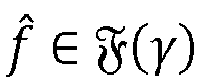
- The function f̂ is chosen within an assigned family of parametric functions(p):


- The choice of said families(p) depends upon the specific methodology used for designing the estimator. For instance, in the case where the estimator is obtained using a mathematical model based upon chemical/physical laws, the vector of parameters p of size q contains a number of parameters of the model, which depend upon the specific type of engine. In the case where a data-driven method is used, for example based upon neural networks, the parametric family may be described as:

US 6,882,929 describes a solution in which a NOx sensor is designed using an artificial neural network. Other solutions for the design/implementation and for a respective use of a virtual sensor are described in the documents Nos.EP 0 712 463 B1 andEP 0 877 309 B1 . - In these methods, the estimated function f̂ is obtained typically by choosing a specific value p̂ for the vector p typically calculated with the procedure described in what follows. It is assumed that there is a number N of data, whereby, in addition to the measured data, i = 1, ..., m for the available variables, measurements ṽ of the variable of interest v are also obtained. To assign the value p̂ to the vector p, an appropriate estimation-error function J(p) is calculated. For instance, one of the most widely used is:


- In general, the value p̂ for the vector of parameters p is hence chosen such that:

-
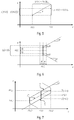
Figure 1 shows in this context an example where just one available variable u 1 is considered and n = 1, i.e., r̃(ti) = [ũ 1(ti - Δt)]. Illustrated in this figure are four data that correspond to the measured values r̃(t 1), r̃(t 2), r̃(t 3), r̃(t 4) of the available variable r and to the measured values ṽ(t 1), ṽ(t 2), ṽ(t 3), ṽ(t 4) of the variable of interest v. Moreover illustrated is the function f̂ in the form fp (r̃) = p 1 + p 2 r̃ + p 3r̃2 that minimises the functional described by Eq. (3). - These methods, however, present important critical features. The first important critical aspect is the calculation of the value p̂ for the vector of parameters p̂ that will satisfy Eq. (4). For instance, typically, the function J(p) is a non-convex function and possibly presents a number of local minima. Consequently, minimisation of Eq. (4) is typically performed using iterative methods starting from an assigned initial value p 0. These methods are not able to guarantee in all cases reaching of the absolute minimum of J(p) and may stop at a relative minimum, with the result that the estimation performance could be even significantly inferior than what can be obtained from the absolute minimum.
- A second critical aspect is the choice of the parametric family(p). A fundamental problem is that of choosing the level of detail of the mathematical models in the case of methods based upon chemical/physical laws, or else the number of base functions in the case of data-driven methods. In both cases, this reflects upon the choice of the size q of the vector p. Values of q that are too small may lead to unacceptable errors. Values of q that are very large may lead to the danger of overfitting; i.e., the estimator obtained achieves acceptable errors only on the data used for deriving the estimator, but not for other data, even ones regarding normal operating conditions. In effect, there do not exist systematic methods for making this choice, which is consequently conducted in a basically empirical manner, frequently requiring even long design times.
- A third important critical feature is the evaluation of the performance of the above methods in relation to the disturbance that may alter the measured variables. Reliable evaluations are obtained only in very particular conditions (linearity, Gaussian disturbances, etc.), which are unlikely to arise in the estimation of complex phenomena as the ones involved in the combustion systems. In particular, in the case investigated here, an important aspect is that, on account of production spread, there may be differences between the data of some variables regarding different engines that are not easy to characterize in statistical terms. This spread may produce unacceptable deterioration in the performance of the virtual sensor designed. It would be important to design a "robust" estimator, capable of achieving acceptable performance even in the presence of production spread. However, this problem is not tackled by any method according to the prior art.
- On account of these problems, none of the above methods appears to have achieved the capacity for estimating the emissions of heat engines with the necessary accuracy required by the operating conditions in which a commercially available vehicle has to work, as highlighted by the limited use on vehicles currently on the market.
- Accordingly, the present application relates to a method of producing a virtual sensor according to the preamble of Claim 1, which is known, e.g. from document
US 6,882,929 . DocumentsUS 2005/022789 A1 ,US 2014/012797 A1 ,US 2010/050025 A1 andUS 2003/216855 A1 may also be of interest for the present application. - The invention is defined by the appended claims. The main object of one or more embodiments of the present disclosure is to overcome the limitations of the solutions proposed by the prior art.
- In various embodiments, the above is obtained by providing a non-parametric estimation process, which avoids the problem of search for the appropriate parametric family of the estimator. Moreover, as regards the disturbances that act on the data used for estimation, it is possible to consider information that is better suited, as compared to the statistical information required in the prior art, to taking into account the production spread. In this way, it is possible to obtain directly a so-called "optimal" estimator, preventing the problems of parametric-statistical methods due to the fact that they might stop on local minima.
- Moreover, in various embodiments, the experimental data are appropriately organised in such a way as to obtain a virtual sensor, referred to as "robustly optimal virtual sensor", which minimises the effects on the estimation errors in the presence of the expected production spread on the data used for the estimate.
- According to various embodiments, the above object is achieved by a method for producing a virtual sensor having the characteristics forming the subject of Claim 1. The claims also regard a corresponding computer-program product.
- The claims form an integral part of the teaching provided in relation to the invention.
- As mentioned previously, various embodiments of the present description regard a process for designing, i.e. producing, a virtual sensor that is able to estimate a variable of interest v as a function of a set of available variables ui , which typically comprises a plurality of variables.
- In various embodiments, a design data-set Dd is acquired, which comprises a number N of measured values ṽ(ti ) of the variable of interest ν and corresponding measured values ũi (ti ) of the available variables ui . For this purpose, the values of the variable of interest ν and of the available variables ui can be measured and stored, during one or more experimental tests with an actuator, such as an engine, using sensors capable of measuring such values (see also
Figure 2 ). Moreover, a limit δ on the disturbances of the available variables ui and a limit η on the errors of the method of measurement of the variable of interest v are determined. For instance, the limit η on the errors of the method of measurement of the variable v can be determined on the basis of the accuracy data of the sensor used for measuring the variable of interest v during the experimental tests, and the limit or limits δ can be determined from the information on the perturbations of the measurements ũi as a result of the process spread involved in (mass) production of the actuator used during the experimental tests and/or as a result of the different operating conditions in which the actuator is operating. - In particular, in various embodiments, the design data-set Dd is modified in such a way as to add values of the variable of interest v and corresponding values of the available variables ui that do not correspond to measured values but that fall within the limit δ around measured values ũi (ti ) of one or more available variables ui and/or within the limit η around measured values ṽ(ti ) of the variable of interest v.
- In various embodiments, a Lipschitz function f* with a respective Lipschitz constant (γ) is then selected, which is designed to estimate the variable of interest ν(t) as a function of a number n of past values of each available variable ui .
- In particular, in various embodiments, the aforesaid Lipschitz function f* is chosen by executing the following steps one or more times for different numbers n.
- At the start, a value for the Lipschitz constant γ is determined. Then, there are defined a maximum limit
f (r(t)) and a minimum limit f (r(t)) for the estimate of the variable of interest v as a function of the design data-set Dd, and moreover the number n, the value for the Lipschitz constant γ, the limit δ on the disturbances of the available variables ui , and the limit η on the errors of the method of measurement of the variable of interest v, and a Lipschitz function f• is chosen comprised between the maximum limitf (r(t)) and the minimum limit f (r(t)). For instance, in various embodiments the value ν(t) of the variable of interest v is estimated with the mean value between the maximum limitf (r(t)) and the minimum limit ƒ (r(t)). - In various embodiments, there is then determined an estimation error ε*(f• ) for each Lipschitz function f •, and there is selected the Lipschitz function f*, associated to which is a respective Lipschitz constant γ* and a respective number n*, that presents the minimum estimation error ε*(f*(γ*, n*)).
- In various embodiments, the selected Lipschitz function f* is then implemented in an electronic circuit. Consequently, the electronic circuit (which corresponds to the virtual sensor) is configured for estimating (by means of the Lipschitz function selected) the variable of interest v as a function of the available variables ui .
- For instance, in various embodiments, for this purpose the selected Lipschitz function f* is approximated with a function fa made up of base functions, and the approximated Lipschitz function fa is implemented in the electronic circuit.
- For instance, in various embodiments, the variable of interest v represents a type of emission of an internal-combustion engine, such as NOx emission, and the set of available variables ui comprises one or more of the following variables: fuel demand, engine r.p.m., engine torque, percentage opening of the EGR valve, percentage closing of the VGT turbine, temperature in the intake manifold, pressure in the intake manifold, pressure in the common rail, flow of exhaust gases in the exhaust manifold, temperature of the coolant, concentration of oxygen in the combustion chamber, absolute humidity, temperature in the combustion chamber, and pressure in the combustion chamber. For instance, in various embodiments, a further virtual sensor is used for estimating the temperature in the combustion chamber and/or the pressure in the combustion chamber. For this purpose, it is possible to design at least one second virtual sensor that is able to estimate a second variable of interest v, for example the temperature in the combustion chamber or the pressure in the combustion chamber, as a function of a second set of available variables. In the embodiment considered, the second variable of interest hence corresponds to one of the available variables ui in the set of available variables ui of the first virtual sensor. In various embodiments, the first virtual sensor and the second virtual sensor can be implemented also within one and the same electronic circuit.
- Embodiments of the present description will now be described in detail with reference to the attached drawings, which are provided purely by way of non-limiting example and in which:
-
Figure 1 has already been described previously; -
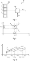
Figure 2 shows an embodiment of a control system; -
Figures 3 shows an embodiment of a virtual sensor that can be used in the system ofFigure 2 ; -
Figure 4 illustrates a flowchart of a process for designing a virtual sensor; -
Figures 5, 6, and 7 show details of the design process ofFigure 4 ; -
Figure 8 illustrates an embodiment of a virtual sensor; -
Figure 9 shows an embodiment that enables reduction of the estimation error of the virtual sensor; -
Figure 10 shows an embodiment that enables reduction of the complexity of the virtual sensor; and -
Figures 11, 12, and 13 show various embodiments of virtual sensors that are particularly useful for estimating a type of emission of an internal-combustion engine. - In the ensuing description, various specific details are illustrated aimed at enabling an in-depth understanding of the embodiments. The embodiments may be provided without one or more of the specific details, or with other methods, components, materials, etc. In other cases, known structures, materials, or operations are not illustrated or described in detail so that various aspects of the embodiments will not be obscured.
- Reference to "an embodiment" or "one embodiment" in the framework of the present description is intended to indicate that a particular configuration, structure, or characteristic described in relation to the embodiment is comprised in at least one embodiment. Hence, phrases such as "in an embodiment" or "in one embodiment" that may be present in various points of the ensuing description do not necessarily refer to one and the same embodiment. Moreover, particular conformations, structures or characteristics may be combined in any adequate manner in one or more embodiments.
- The references used herein are merely provided for convenience and hence do not define the sphere of protection or the scope of the embodiments.
- As mentioned previously, the present description relates to solutions for designing a virtual sensor, such as a virtual sensor that is able to estimate one or more types of emission of an internal-combustion engine, for example NOx emission of a diesel engine.
-
Figure 2 shows an embodiment of a generic control system. - In the embodiment considered, the system comprises an
actuator 10 and acontrol unit 20 configured to drive theactuator 10 on the basis of one or more control signals. For instance, in the embodiment considered, thecontrol unit 20 can drive theactuator 10 on the basis of one or more of the following control signals: - one or more reference signals S1;
- one or more signals of a feed-back type S2, i.e., signals obtained via one or
more sensors 30 configured for monitoring the behaviour of theactuator 10; and - one or more signals of a feed-forward type S3, i.e., signals obtained from one or more
further sensors 32 that supply information useful for a predictive control. - In general, there may also be provided one or more
further sensors 34 configured for monitoring the behaviour of theactuator 10, which, however, are not used for control of theactuator 10. - For instance, in various embodiments, the
actuator 10 is an internal-combustion engine. In this case, thecontrol unit 20 is typically implemented within the engine control unit, and the reference parameter S1 could be the required value of engine r.p.m. - In various embodiments, at least one of the
sensors virtual sensor 40; i.e., at least one of the signals S2, S3, and/or S4 corresponds to an estimate v̂ of a variable of interest v. - In general, the
virtual sensor 40 can be implemented within thecontrol unit 20, for example in the form of a software module, or on a separate electronic board. - Consequently, as illustrated in
Figure 3 , thevirtual sensor 40 receives, at each sampling instant ti = i·Δt, a set of measured values MQ = {ũ 1 , ũ 2 , ..., ũm } and estimates a corresponding value ν̂(t) for the variable of interest ν(t) as a function of the measured values MQ. For instance, in the architecture illustrated inFigure 2 , thecontrol module 20 can send these measured values to thevirtual sensor 40. For example, as mentioned previously, thevirtual sensor 40 could be a software module within thecontrol unit 20 that preferably has direct access to the variables acquired and/or calculated within thecontrol unit 20. Instead, in the case where thevirtual sensor 40 is implemented on a separate electronic board, thecontrol module 20 can exchange the values with thevirtual sensor 40 through any wired or wireless communication system, such as a CAN (Controller Area Network) bus of a vehicle. In general, thevirtual sensor 40 could receive one or more of the measured values also directly from thevarious sensors - For instance, in various embodiments, the variable of interest ν(t) that is to be measured is a type of emission produced by the
engine 10, for example NOx. By way of example, appearing in the following table are variables that can be used in various embodiments for estimation of NOx:Name of variable Description ũ 1 Fuel demand ũ 2 Engine r.p.m. ũ 3 Engine torque ũ 4 Percentage opening of the EGR valve ũ 5 Percentage closing of the VGT turbine ũ 6 Temperature in the intake manifold ũ 7 Pressure in the intake manifold ũ 8 Pressure in the common rail ũ 9 Flow of exhaust gases in the exhaust manifold ũ 10 Temperature of the coolant ũ 11 Concentration of oxygen in the combustion chamber ũ 12 Absolute humidity - Consequently, in general the
virtual sensor 40, on the basis of the variables MQ, supplies in real time an estimate v̂ of the variable of interest v, for example of engine emission, such as emission of uncombusted hydrocarbons (HC), nitrogen oxides (NOx), carbon monoxide (CO), or particulate matter (PM). -
Figure 4 shows an embodiment of a process for designing thevirtual sensor 40, which can be implemented, for example, within a software for the design of virtual sensors, i.e., a computer-program product that can be executed, for example, on a computer or a computing system with distributed architecture (the so-called cloud-computing system), which implements the process for automatic design of thevirtual sensor 40. - After an
initial step 1000, astep 1002 is carried out of acquisition of data Dd for acquiring both the measured values MQ = {ũ 1, ũ 2, ... ,ũm } and the corresponding measured values ṽ of the variable of interest ν:
- The acquisitions of the above reference data Dd may be made by means of experimental measurements on a
testing actuator 10, either in the laboratory or during actual operation, or else by means of simulations of an accurate model of theactuator 10, or else in part experimentally and in part by simulation. For instance, in various embodiments, the reference data Dd are acquired using operating conditions that are typically considered for evaluating the performance of theactuator 10, for example of the engine and its emission levels. For instance, these conditions may comprise both dynamic tests (homologation cycles such as NEDC, WLTP, FTP, Artemis) and actual on-the-road tests, as well as stationary tests conducted on different possible engine operating points. - The set of reference data Dd is then used in a
step 1004 for designing thevirtual sensor 40. As will be described hereinafter, in various embodiments, thestep 1004 comprises astep 1006 for computing a function f• that is able to provide a robust estimate, i.e., with a guaranteed error limit even in the presence of variability of the variables ui due to the spread in the engine-production processes, anoptimisation step 1008 for computing a function f* that yields a robustly optimal estimate, which minimises the guaranteed error, and anoptional approximation step 1010 for approximating the function f* with a function fa with reduced computational complexity. - In various embodiments, the functions f•, f*, or fa may be used, in a
step 1012, for implementing thevirtual sensor 40. For instance, in various embodiments,step 1012 can automatically generate a source code that can be transferred onto the platform on which it will have to operate, such as a source code (for example, a C code) that can be compiled for the control unit 20 (for example, the engine control unit) or another microprocessor, or a VHDL/VERILOG code for programming of an FPGA or for implementation of an ASIC. - In general, as already mentioned in the section "Description of the prior art", an estimator of the variable of interest ν based upon the variables MQ may be represented as in Eq. (1). In various embodiments, unlike the technique used in the prior art, the functions f•, f*, or fa are not sought within an assigned parametric family, but rather within a non-parametric family(γ) of continuous Lipschitz functions. For instance, in various embodiments, the following family of functions is used:


- The set Rb is the rectangular parallelepiped in the space Rm×n of minimum volume that contains the set Rd made up of all the regressors formed using the data of the data-set Dd and can be calculated as:

- Consequently, the set Rb defines the space between the minimum and maximum measured values of the variables ũi , hence being automatically limited to the range of the values actually measured.
-
Figure 5 shows, in this context, two arbitrary points r̂(t), ř(t) in the set Rb . Basically, Eq. (6) envisages that the distance between the two values f(r̂(t)) and f(ř(t)) must be less than the distance between the two points r̂(t), ř(t), determined as shown in Eq. (6), for example with the infinity norm or alternatively another norm, for example the Euclidean norm, multiplied by the Lipschitz constant γ. - The rationale for the previous choices stems from the following considerations. The
actuator 10, for example the engine, which represents an emission-generation system, may, in general, be described by a system of nonlinear state equations of appropriate order n, of which the variables ui are in part the inputs and in part the measured outputs. If the variable of interest v (for example, the emission) is a continuous Lipschitz function of the state variables and can be estimated from a knowledge of the variables ui , then, from the general theory of observability of nonlinear systems, there exists a function ƒ 0 such that, for an appropriate value of γ,
- The function f 0 is in general not known, and in various embodiments an estimate thereof is directly derived from the experimental data. It may be noted that the family of functions(γ) where estimation functions f• and f* are sought is constituted by functions that, operating on measurements ui corrupted by disturbances that are not known but are limited by a value δ ≥ |ui - ũi |, yield estimation errors that (as will be illustrated hereinafter) are limited by the amount γδ .
- In various embodiments, this property is used in
step 1004 for computing the functions f• and f* that enable so-called robust and robustly optimal estimators to be obtained, capable of supplying a low or even minimum estimation error that can be obtained in the various operating conditions in which the estimator will have to operate and in the presence of disturbances on the measurements ui that, on account of production spread, are not known but are smaller in modulus than δ. - Moreover, the performance of any


- In general, the data contained in the data-set Dd do not yield information on the behaviour of the function f̂ outside of the data-set Rb defined in Eq. (7). In fact, two estimation functions f̂a,

- In various embodiments, for assigning functions


- In fact, from Eq. (8), we have:

- Moreover, the limit |ui - ũi | ≤ δ implies that:

- Consequently, from Eqs. (8) and (12), it follows that

- Hence from Eqs. (11) and (13) we have

- Consequently, in various embodiments, design of the
virtual sensor 40 is based upon the fact that the function f 0 is not known, but it is known that

- For instance,
Figure 6 shows an arbitrary measured regressor r̃(t), which for simplicity comprises just one variable u 1, and the respective measured value ṽ(t). In general, the measured value ṽ has an uncertainty due to the measurement that is limited by η, and likewise the measured value for the variable u 1 has a respective limit δ on the disturbances. Consequently, the overall uncertainty, assuming that the function f 0 is a Lipschitz function with constant γ, is limited by the sum of η (uncertainty of measurement of ṽ) and γδ (possible variation of the function f 0 in the limit δ on the disturbances of u 1). This uncertainty hence defines the set of values of the function f 0 for a given measured regressor r̃(t) and respective measured value ṽ of the variable of interest v. As already explained, the function f 0 is not known. However, thedesign step 1006 can exploit the fact that, if the Lipschitz constant γ is such that the set of functions FFS is not an empty set, from Eq. (15) we have the information that

- Consequently, the minimum limit that may be obtained from Eq. (14) for assigned function

- From Eq. (17) it hence follows that for any function

- In various embodiments, in step 1006 a function f •(γ) is hence determined such as to minimise for the assigned value of γ the limit of the estimation error:

- The function f •(γ) is determined as described in what follows, on the basis of the "set-membership" theory, as described, for example, in the paper by Milanese, M., Novara, C., "Set membership identification of nonlinear systems", Automatica, 40, pp. 957-975, 2004.
- In particular, in various embodiments, a maximum value
f (r(t)) is determined for the variable v as a function of the regressor currently measured r̃(t):
- Likewise, a minimum value f (r(t)) is obtained for the variable v as a function of the regressor currently measured r̃(t):

-
Figure 7 shows in this context an example in which just a single available variable ũ 1 is considered and n = 1, i.e., r̃(ti ) = [ũ 1(ti - Δt)]. In this figure, two data are shown, which correspond, respectively, to the measured values r̃(t 1), r̃(t 2) and to the measured values ṽ(t 1), ṽ(t 2) of the variable of interest v, and the functionsf and f are calculated according to Eqs. (18) and (19). - In various embodiments, the
virtual sensor 40, in particular theprocessing unit 400, is configured for estimating the value v*(t) as the mean value between the maximum valueƒ (r(t)) and the minimum value f (r(t)), i.e., by computing the value v*(t) with the following function f•∀r̃(t) ∈ Rb (see alsoFigure 7 ):
- Consequently, the maximum error ε* of the function f • is limited to

- The function f• is a function of the Lipschitz constant γ and of the memory n of the estimator, the dependence of which will be expressed only if necessary and which must be chosen in such a way that the set FFS is not empty. For instance, a condition that is necessary and sufficient for this set not to be empty is the following:

- In various embodiments, in
step 1006 thevirtual sensor 40 is designed with a given n, and the minimum Lipschitz constant γ*(n) that satisfies Eq. (22) is calculated as follows:
- Hence, each pair of values n, γ*(n) is such that FFS is not empty.
- In various embodiments, the
previous step 1006 is then repeated for other values of n in such a way as to choose a value n* such that:
step 1008 in accordance with Eq. (21), as follows:
- In various embodiments, there are hence chosen n = n* and γ = γ* that enable calculation of the function f*=f• (γ*, n*), which yields a robustly optimal estimator, i.e., one such that ε*(f*) is the minimum estimation error that can be guaranteed for any validation data-set

- Calculation of Eq. (23) is quite easy, whereas calculation of Eq. (25) is more complex, and it is substantially possible to use the method described in the paper by Milanese, M., Novara, C., "Computation of local radius of information in SM-IBC identification of non-linear systems", J. Complexity 23, pp. 937-951, 2007.
-
Figure 8 shows in this context an embodiment of avirtual sensor 40. In the embodiment considered, thevirtual sensor 40 comprises aprocessing unit 400, such as a microprocessor programmed with a computer program or a digital circuit, and one ormore memories 402. As explained previously, thevirtual sensor 40 may be implemented, for example, within thecontrol unit 20 or on a separate electronic circuit. - In various embodiments, in
step 1012 the following data are stored in the memory 402: - the measured data in the design data-set Dd;
- the Lipschitz constant γ;
- data that identify the term η + γδ, for example directly the limit η on the errors of the method of measurement of the variable v and the limit δ on the disturbances of the data of the variables ui .
- Moreover, in various embodiments, the
virtual sensor 40 is configured for receiving the current regressor r̃(t) and computing the maximum valueƒ (r(t)) and the minimum value f (r(t)) for the current regressor r̃(t), as illustrated in Eqs. (18) and (19). - Consequently, in various embodiments, the estimator f* depends upon the experimental data included in the design data-set Dd, upon η, γ, δ, and upon the memory n of the estimator. In general, the memory n of the estimator may even be a vector; i.e., each available variable ũ i could have a respective memory ni . In this case, the
step 1006 could hence be repeated for various combinations of values ni , once again choosing instep 1008 the combination that presents the minimum error, as shown in Eq. (25). - In various embodiments, the limit η on the errors of the method of measurement of the variable v can be chosen from the data of accuracy of the instrument for measuring v used during the experimental tests, and the limit δ can be derived from the information on the perturbations of the measurements ũi resulting from process spread involved in (mass) production of the
actuator 10, for example of the engine, and from the different operating conditions of theactuator 10. In general, the limit δ may even be a vector; i.e., each available variable ũ i could have a respective limit δi . However, one or more available variables ũ i can be normalized in such a way as to use the same limit δ. - As explained previously, in various embodiments, the design data-set Dd is modified in such a way as to reflect the limit η on the errors of the method of measurement of the variable v and/or the limit δ on the disturbances of the data of the variables ui .
- For instance, as illustrated in
Figure 9 , in various embodiments, one or more data Pv, i.e., combinations {ũ 1(ti ), ũ 2(ti ), ..., ũm (ti ), ṽ(ti )}, are added to the data-set Dd that normally contains only measured data PM. In particular, these added points Pv are chosen so as to reflect the limit η on the errors of the method of measurement of the variable v and/or the limit δ on the disturbances of the data of the variables ui . For instance, in various embodiments one or more data Pv are added within the area delimited by the limits ±η and ±δ with respect to a measured point PM, thus emulating the tolerances of measurement and/or production, etc. For instance, inFigure 9 two data Pv1 and Pv2 are added. - For example, in various embodiments, four additional data are added for each measured datum PMi = r̃(ti ), ṽ(ti )] in the data-set Dd ; namely,




- The above additional data Pv are subsequently considered as measured data PM, i.e., the
subsequent design step 1004 treats indistinctly the measured data PM and the additional data Pv in the data-set Dd. - In this way, the estimator takes into account the fact that there may be data with equal errors δ, thus improving the characteristics of robustness of the estimator.
- The
virtual sensor 40 that directly implements the set-membership solution f*(γ*, n*) described previously is a robustly optimal solution, which, however, could require computing times and occupation of memory that are not compatible with the performance of the hardware platform on which it has to operate in real time. - In various embodiments, the
optional step 1010 thus provides a procedure that enables an approximation fa of f* to be obtained, evaluating balancing between degradation of the accuracy of the estimate and reduction of the computing times and of occupation of memory. - For instance, in various embodiments, an approximating function fa is sought such that

- In various embodiments, the approximating function fa is chosen of the form:

- In particular, Eqs. (26) and (27) differ from those of the prior art, since the approximated function fa (r) is not calculated as a function of the measured values ṽ(ti ), but the corresponding estimate f*(r̃(ti )) is used, which hence takes into consideration also the limit η on the errors of the method of measurement of the variable v and the limit δ on the disturbances of the data of the variables ui .
-
Figure 10 shows an embodiment that enables further improvement of the result of the approximation. In particular, in the embodiment considered, the function fa(r) is estimated not only using in Eq. (26) the measured regressors r̃(ti ), i = n + 1, ..., N, but also adding further regressors r̃v (ti ), which hence increase the number of points used for estimation of the function fa (r). - In various embodiments, in order to prevent phenomena of overfitting, approximated functions fa are sought with the minimum number of ai ≠ 0 that will in any case guarantee the assigned level µ of precision to be achieved. This problem is in general an NP-hard problem, so that typically its solution cannot be obtained in computing times that are acceptable for the problems considered in this description. However, it is possible to use approximate solutions proposed in the literature that are such as to lead to a number of elements ai ≠ 0, which, even though it is not equal to the minimum number that guarantees the assigned level µ of precision to be achieved, is in general much smaller than Ms ; see, for example, the paper by Novara C., Fagiano L., Milanese M., "Sparse Set Membership Identification of Nonlinear Functions", 50th IEEE Conference on Decision and Control, Orlando, 2011, and the references appearing therein.
- For instance, in various embodiments, a two-step convex optimisation is used.
- We define:


- z λ (a): subset of z(a) ⊂ λ = {1, 2, ..., k}
- card(r(a)): number of elements of r(a)
-
supp (a) = {i ∈ {1,2, ..., MS }: ai = 0} - In various embodiments, the following optimisation problem is first solved for the initial vector a 1:


- In the first step, the vector a 1 is thus obtained by solving a convex-optimisation problem, which in general yields a large number of coefficients

- In various embodiments, the optimal vector a* is then calculated with the following optimisation algorithm:

- Consequently, in the second step only a part of the elements of a 1 are progressively included in the vector a* as long as Eq. (26) applies. In this way, it is possible to obtain a vector a* the nonzero elements of which are typically in a number m*, which is considerably smaller than that of the initial solution a 1. Consequently, the function

-
Figure 11 shows in this context a first embodiment of avirtual sensor 40a that is able to estimate the NOx emission of an engine. For instance, during design of thevirtual sensor 40a the inputs listed previously have been used, namely, the variables ũ 1, ... ũ 12 . For instance, the respective design data-set Dd may be obtained with NEDC, WLTP, FTP and Artemis dynamic homologation tests with engine hot and engine cold, with stationary tests, and with real-drive tests, acquired with a respective sampling period, for example, Δt = 1s. - In various embodiments, the input variables have been modified in such a way as to simulate not only the different operating conditions but also the process spread involved in mass-production of the engine. For instance, in various embodiments, the inputs concerned by the aforesaid perturbations used as inputs of the
virtual sensor 40 are ũ 3 (engine torque with a perturbation of ±5%), ũ 6 (temperature in the intake manifold with a perturbation of ±3°C), and ũ 7 (pressure in the intake manifold with a perturbation of ±40 mbar). - In the embodiment considered, the number of experimental data that constitute the design data-set Dd is N = 105.
- Using the design process described previously for implementation on a 32-bit board with a clock frequency of 120 MHz, the estimator f* obtained with the set-membership procedure requires an occupation of memory of 5 MB and a computing time necessary for estimation of v*, at each sampling period Δt = 1s, of 780 ms.
- Instead, to obtain an estimation function

step 1010 an approximating function has been chosen as in Eq. (27) with a number of polynomial base functions Ms = N. In fact, the smaller the value of µ, the more closely

-
Figure 13 shows a second embodiment of avirtual sensor 40b that is able to estimate the emission of an engine (for example, NOx), where, in addition to the variables ũ 1, ... ũ 12 , two further available variables ũ 13 and ũ 14 are also considered, which correspond to the pressure p and to the temperature T in the combustion chamber. The design data-set Dd used for designing thevirtual sensor 40 hence comprises measurements also for these variables ũ 13 = p and ũ 14 = T. However, physical sensors for detecting the temperature and pressure in the combustion chamber are costly, and their precision deteriorates rapidly on account of the conditions in which they operate. - Figure 14 shows a third embodiment of a
virtual sensor 40c that is able to estimate the emission of an engine (for example, NOx). - In particular, to overcome technological problems of physical sensors for detecting the temperature and pressure in the combustion chamber, the physical sensor for detecting the temperature in the combustion chamber and/or the physical sensor for detecting the pressure in the combustion chamber have/has been replaced with
virtual sensors virtual sensor 40c may in actual fact comprise three virtual sensors: - a first
virtual sensor 40d designed to estimate temperature T̂ in the combustion chamber; - a second
virtual sensor 40e designed to estimate the pressure p̂ in the combustion chamber; and - a third
virtual sensor 40b designed to estimate the engine emission (for example, NOx), which receives all the variables ũ 1 ... ũ 14, i.e., also the available variables ũ 13 and ũ 14, which correspond, however, to the estimates T̂ and p̂ of the temperature and of the pressure in the combustion chamber. - In various embodiments, the
virtual sensors - It may be noted that the
estimators sensors virtual sensor 40d that is able to estimate the temperature T̂ in the combustion chamber is designed only as a function of the variables ũ 2 (engine r.p.m.), ũ 3 (engine torque), and ũ 4 (percentage opening of the EGR valve). Instead, in various embodiments, thevirtual sensor 40e that is able to estimate the pressure p̂ in the combustion chamber is designed only as a function of the variables ũ 1 (fuel demand), ũ 2 (engine r.p.m.), and ũ 7 (pressure in the intake manifold). - Hence, in the embodiment considered, the entire
virtual sensor 40c (Figure 14) uses as inputs ui those of thevirtual sensor 40a (Figure 12 ), but as compared to the latter enables higher levels of precision to be achieved comparable with those of thevirtual sensor 40b (Figure 13 ). This is justified by the fact that, for the step of design of thevirtual sensors virtual sensor 40a. Consequently, in this solution the information content of the design data-set is greater than the information content of the data-set used for the single-stage design, thus enabling improvement of the estimation performance. - Various embodiments of the present disclosure hence regard a virtual sensor 40 (for example, the
virtual sensor 40c) configured for estimating a variable of interest v and comprising: - a first virtual sensor (for example, the
virtual sensor 40b) configured for estimating the variable of interest v, where the first virtual sensor is designed according to the process described herein using a design data-set comprising measured values ṽ(t) of the variable of interest and corresponding measured values ũi of a given set of available variables ui , - at least one second virtual sensor (for example, the
virtual sensors 40d and/or 40e) configured for estimating a second variable of interest, where the second variable of interest corresponds to one of the available variables ui used by the first virtual sensor, and where the second virtual sensor is designed according to the process described herein using a second design data-set comprising measured values of the second variable of interest and corresponding measured values ũ i of a given second set of available variables ui . - In particular, in various embodiments, the first and second virtual sensors use at least in part the same available variables ui .
- Moreover, it would also be possible to design the second virtual sensor first and use, for design of the first virtual sensor, values already estimated with the second virtual sensor.
- Of course, without prejudice to the principle of the invention, the details of construction and the embodiments may vary widely with respect to what has been described and illustrated herein purely by way of example, without thereby departing from the scope of the present invention, as defined by the ensuing claims.
Claims (10)
- A method of producing a first virtual sensor (40) configured to estimate a variable of interest v as a function of a set of available variables ui provided by a plurality of sensors (20, 30, 32, 34), wherein said variable of interest v is indicative of an emission of an internal combustion engine (10), the method comprising the steps of:- acquiring (1002) by means of experimental measurements on a testing internal combustion engine (10) and/or by means of simulations of an accurate model of said internal combustion engine (10) a design dataset Dd comprising a number N of measured values ṽ(ti ) of said variable of interest v and corresponding measured values ũi (ti ) of said available variables ui ;- determining a function adapted to estimate the variable of interest v(t) as a function of a number n of past values of each available variable ui ; and- implementing (1012) said function in an electronic circuit, whereby said electronic circuit is configured to estimate said variable of interest ν(t) as a function of said set of available variables ui ;characterized in that the method comprises the steps of:- determining a boundary δ of the disturbances of said available variables ui as a function of the information on the perturbations of the measurements as a result of the production tolerances of said internal combustion engine (10) and the different operating conditions in which said internal combustion engine (10) is operating, and determining a boundary η of the measurement errors of the variable of interest v as a function of the accuracy data of the sensor used for measuring the variable of interest v during the experimental tests;- selecting (1004) a Lipschitz function f* with a respective Lipschitz constant (γ) adapted to estimate the variable of interest v(t) as a function of a number n of past values of each available variable ui by executing the following steps one or more times for different numbers n:a) determining a value for said Lipschitz constant γ;b) defining (1006) an upper boundary
f (r(t)) and a lower boundary f (r(t)) for the estimation of said variable of interest v as a function of said design dataset Dd, the number n, said value for said Lipschitz constant γ, said boundary δ of the disturbances of said available variables ui and said boundary η of the measurement errors of the variable of interest v, and selecting a Lipschitz function f • comprised between said upper boundaryƒ (r(t)) and said lower boundary f (r(t));c) determining (1008) an estimation error ε*(f •) for said Lipschitz function f • and selecting the Lipschitz function f*, having associated a respective Lipschitz constant γ* and a respective number n*, which has the lowest estimation error ε*(f*(γ*, n*));- implementing (1012) said selected Lipschitz function f* in said electronic circuit. - Method according to Claim 1, wherein said value for said Lipschitz constant γ is determined with the following equation:

- Method according to Claim 1 or Claim 2, wherein said upper boundary
f (r(t)) and said lower boundary f (r(t)) for the estimation of said variable of interest v are defined through the following equations:

- Method according to any of the previous claims, wherein said selecting a Lipschitz function f • comprised between said upper boundary
ƒ (r(t)) and said lower boundary f (r(t)) comprises estimating the value v(t) of the variable of interest v with the average value between the upper boundaryƒ (r(t)) and the lower boundary ƒ (r(t)). - Method according to any of the previous claims, comprising:- modifying said design dataset Dd in order to add values of said variable of interest v and corresponding values of said available variables ui which do not correspond to measured values but which are within the boundary δ around measured values ũi (ti ) of one or more of said available variables ui and/or the boundary η around measured values ṽ(ti ) of said variable of interest v.
- Method according to any of the previous claims, comprising:- approximating (1010) said selected Lipschitz function f* with a function fa being composed of base functions; and- implementing (1012) said approximated Lipschitz function fa in said electronic circuit.
- Method according to any of the previous claims, comprising:- designing at least a second virtual sensor (40d, 40e) adapted to estimate a second variable of interest v as a function of a second set of available variables, wherein the second variable of interest corresponds to one of the available variables u i in said set of available variables ui of said first virtual sensor (40b), wherein the second virtual sensor (40d, 40e) is designed using a second design dataset comprising measured values of said second variable of interest and corresponding measured values for said second set of available variables; and- implementing said first virtual sensor and said second virtual sensor within the same electronic circuit.
- Method according to any of the previous claims, wherein said set of available variables ui comprises one or more of the following variables:- fuel demand;- engine r.p.m.;- engine torque;- temperature in the intake manifold;- pressure in the intake manifold;- pressure in the common rail;- flow of exhaust gases in the exhaust manifold;- temperature of the coolant;- concentration of oxygen in the combustion chamber;- absolute humidity;- temperature in the combustion chamber; and- pressure in the combustion chamber.
- Method according to any of the previous claims, wherein said variable of interest v is indicative of an emission of NOx of said internal combustion engine (10).
- A computer-program product that can be loaded into the memory of at least one processor and comprises portions of software code for implementing the steps of the method according to any of Claims 1 to 9.
Applications Claiming Priority (2)
| Application Number | Priority Date | Filing Date | Title |
|---|---|---|---|
| IT102016000098423A IT201600098423A1 (en) | 2016-09-30 | 2016-09-30 | PROCEDURE FOR THE DESIGN OF A VIRTUAL SENSOR, ITS VIRTUAL SENSOR, SYSTEM AND IT PRODUCTS |
| PCT/IB2017/055843 WO2018060847A1 (en) | 2016-09-30 | 2017-09-26 | Process for designing a virtual sensor, corresponding virtual sensor, system, and computer-program products |
Publications (2)
| Publication Number | Publication Date |
|---|---|
| EP3519996A1 EP3519996A1 (en) | 2019-08-07 |
| EP3519996B1 true EP3519996B1 (en) | 2021-08-04 |
Family
ID=57960641
Family Applications (1)
| Application Number | Title | Priority Date | Filing Date |
|---|---|---|---|
| EP17785017.9A Active EP3519996B1 (en) | 2016-09-30 | 2017-09-26 | Process for designing a virtual sensor, corresponding virtual sensor, system, and computer-program products |
Country Status (5)
| Country | Link |
|---|---|
| US (1) | US10859022B2 (en) |
| EP (1) | EP3519996B1 (en) |
| CN (1) | CN110121708B (en) |
| IT (1) | IT201600098423A1 (en) |
| WO (1) | WO2018060847A1 (en) |
Families Citing this family (6)
| Publication number | Priority date | Publication date | Assignee | Title |
|---|---|---|---|---|
| DE102018208683A1 (en) * | 2018-06-01 | 2019-12-05 | Robert Bosch Gmbh | Method and control unit for regulating a fill level of a storage tank of a catalytic converter for an exhaust gas component |
| US10895854B1 (en) * | 2019-07-03 | 2021-01-19 | Mitsubishi Electric Research Laboratories, Inc. | System and method for control constrained operation of machine with partially unmodeled dynamics using Lipschitz constant |
| DE102019121589A1 (en) * | 2019-08-09 | 2021-02-11 | Compredict Gmbh | Procedure for determining a sensor configuration |
| CN113343458B (en) * | 2021-05-31 | 2023-07-18 | 潍柴动力股份有限公司 | Engine sensor type selection method, device, electronic equipment and storage medium |
| US12129783B2 (en) * | 2022-03-25 | 2024-10-29 | Ford Global Technologies, Llc | System and methods for estimating emissions |
| CN115798624B (en) * | 2023-02-01 | 2023-06-09 | 中国汽车技术研究中心有限公司 | Intelligent modeling method for diesel vehicle tail gas SCR reaction process |
Family Cites Families (13)
| Publication number | Priority date | Publication date | Assignee | Title |
|---|---|---|---|---|
| US6711489B2 (en) * | 2001-12-05 | 2004-03-23 | Visteon Global Technologies, Inc. | Method for estimating engine cylinder variables using second order sliding modes |
| US6882929B2 (en) * | 2002-05-15 | 2005-04-19 | Caterpillar Inc | NOx emission-control system using a virtual sensor |
| EP1477651A1 (en) * | 2003-05-12 | 2004-11-17 | STMicroelectronics S.r.l. | Method and device for determining the pressure in the combustion chamber of an internal combustion engine, in particular a spontaneous ignition engine, for controlling fuel injection in the engine |
| PT1788461E (en) * | 2005-11-22 | 2009-09-24 | Faculte Polytechnique De Mons | A device for and a method of designing a sensor arrangement for a safe automated system, an automated system, a program element and a computer-readable medium |
| US8478506B2 (en) * | 2006-09-29 | 2013-07-02 | Caterpillar Inc. | Virtual sensor based engine control system and method |
| EP2191405B1 (en) * | 2007-06-27 | 2019-05-01 | Roche Diabetes Care GmbH | Medical diagnosis, therapy, and prognosis system for invoked events and method thereof |
| US7917333B2 (en) * | 2008-08-20 | 2011-03-29 | Caterpillar Inc. | Virtual sensor network (VSN) based control system and method |
| US20140012791A1 (en) * | 2012-07-05 | 2014-01-09 | Caterpillar Inc. | Systems and methods for sensor error detection and compensation |
| US20150006433A1 (en) * | 2013-03-15 | 2015-01-01 | C4Cast.Com, Inc. | Resource Allocation Based on Available Predictions |
| FR3017705B1 (en) * | 2014-02-18 | 2017-07-07 | Airbus Operations Sas | METHOD OF MELTING SENSOR DATA. |
| WO2016020834A1 (en) * | 2014-08-04 | 2016-02-11 | Modelway S.R.L. | A method for estimating variables affecting the vehicle dynamics and corresponding virtual sensor |
| US20160117594A1 (en) * | 2014-10-22 | 2016-04-28 | Yandy Perez Ramos | Method and system for developing a virtual sensor for determining a parameter in a distributed network |
| US10487767B2 (en) * | 2017-03-17 | 2019-11-26 | Ford Global Technologies, Llc | Method and system for monitoring air filter condition |
-
2016
- 2016-09-30 IT IT102016000098423A patent/IT201600098423A1/en unknown
-
2017
- 2017-09-26 US US16/338,220 patent/US10859022B2/en active Active
- 2017-09-26 CN CN201780060554.2A patent/CN110121708B/en active Active
- 2017-09-26 WO PCT/IB2017/055843 patent/WO2018060847A1/en not_active Ceased
- 2017-09-26 EP EP17785017.9A patent/EP3519996B1/en active Active
Also Published As
| Publication number | Publication date |
|---|---|
| US20200032731A1 (en) | 2020-01-30 |
| CN110121708B (en) | 2023-08-18 |
| CN110121708A (en) | 2019-08-13 |
| US10859022B2 (en) | 2020-12-08 |
| IT201600098423A1 (en) | 2018-03-30 |
| WO2018060847A1 (en) | 2018-04-05 |
| EP3519996A1 (en) | 2019-08-07 |
Similar Documents
| Publication | Publication Date | Title |
|---|---|---|
| EP3519996B1 (en) | Process for designing a virtual sensor, corresponding virtual sensor, system, and computer-program products | |
| Wang et al. | NOx emissions prediction based on mutual information and back propagation neural network using correlation quantitative analysis | |
| Mohammadpour et al. | A survey on diagnostic methods for automotive engines | |
| JP2019190306A (en) | Mechanical learning device of unburnt fuel quantity | |
| Pla et al. | Simultaneous NO x and NH 3 slip prediction in a SCR catalyst under real driving conditions including potential urea injection failures | |
| Soleimani et al. | Reliability challenges for automotive aftertreatment systems: a state-of-the-art perspective | |
| Guardiola et al. | ECU-oriented models for NOx prediction. Part 1: a mean value engine model for NOx prediction | |
| US20220351022A1 (en) | Method and Arrangement for Predicting Engine Out Nitrogen Oxides (EONOx) using a Neural Network | |
| Petrillo et al. | Improving the NOx reduction performance of an Euro VI d SCR System in real-world condition via nonlinear model predictive control | |
| Pla et al. | Ammonia injection optimization for selective catalytic reduction aftertreatment systems | |
| Guardiola et al. | An on-board method to estimate the light-off temperature of diesel oxidation catalysts | |
| Kihas et al. | Engine-Out NOx models for on-ECU implementation: A brief overview | |
| Singalandapuram Mahadevan et al. | Development of a Kalman filter estimator for simulation and control of particulate matter distribution of a diesel catalyzed particulate filter | |
| Guardiola et al. | A bias correction method for fast fuel-to-air ratio estimation in diesel engines | |
| Sapio et al. | Neural-network-based modeling of SCR systems for emission simulation: A comprehensive approach | |
| Rainer et al. | Iterative DoE-improved emission models and better optimisation results within a shortened measurement time | |
| Barbier et al. | Predicting instantaneous engine-out NOx emissions in a real-driving vehicle data scenario | |
| Uppalapati et al. | Development and validation of engine calibration using 1d predictive models | |
| Giovannardi et al. | AI-based virtual sensing of gaseous pollutant emissions at the tailpipe of a high-performance vehicle | |
| Mentink et al. | Experimental validation of a virtual engine-out NOx sensor for diesel emission control | |
| US7664593B2 (en) | Method and system for estimating exhaust gas temperature and internal combustion engine equipped with such a system | |
| Yuan et al. | A novel NH3 slip control for diesel engine selective catalytic reduction aftertreatment system | |
| Barbier et al. | Predicting NOx emissions during sensor light-off by leveraging sensor layout diversity in connected fleets | |
| CN114961949A (en) | Fault diagnosis method, device, equipment and medium for SCR system | |
| Piffl | Countermeasures to Ensure Conformity of Production |
Legal Events
| Date | Code | Title | Description |
|---|---|---|---|
| STAA | Information on the status of an ep patent application or granted ep patent |
Free format text: STATUS: UNKNOWN |
|
| STAA | Information on the status of an ep patent application or granted ep patent |
Free format text: STATUS: THE INTERNATIONAL PUBLICATION HAS BEEN MADE |
|
| PUAI | Public reference made under article 153(3) epc to a published international application that has entered the european phase |
Free format text: ORIGINAL CODE: 0009012 |
|
| STAA | Information on the status of an ep patent application or granted ep patent |
Free format text: STATUS: REQUEST FOR EXAMINATION WAS MADE |
|
| 17P | Request for examination filed |
Effective date: 20190329 |
|
| AK | Designated contracting states |
Kind code of ref document: A1 Designated state(s): AL AT BE BG CH CY CZ DE DK EE ES FI FR GB GR HR HU IE IS IT LI LT LU LV MC MK MT NL NO PL PT RO RS SE SI SK SM TR |
|
| AX | Request for extension of the european patent |
Extension state: BA ME |
|
| DAV | Request for validation of the european patent (deleted) | ||
| DAX | Request for extension of the european patent (deleted) | ||
| REG | Reference to a national code |
Ref country code: DE Ref legal event code: R079 Ref document number: 602017043441 Country of ref document: DE Free format text: PREVIOUS MAIN CLASS: G06F0017500000 Ipc: G06F0030150000 |
|
| GRAP | Despatch of communication of intention to grant a patent |
Free format text: ORIGINAL CODE: EPIDOSNIGR1 |
|
| STAA | Information on the status of an ep patent application or granted ep patent |
Free format text: STATUS: GRANT OF PATENT IS INTENDED |
|
| RIC1 | Information provided on ipc code assigned before grant |
Ipc: F01N 9/00 20060101ALI20210208BHEP Ipc: G06F 30/30 20200101ALI20210208BHEP Ipc: G06F 30/15 20200101AFI20210208BHEP |
|
| INTG | Intention to grant announced |
Effective date: 20210225 |
|
| GRAS | Grant fee paid |
Free format text: ORIGINAL CODE: EPIDOSNIGR3 |
|
| GRAA | (expected) grant |
Free format text: ORIGINAL CODE: 0009210 |
|
| STAA | Information on the status of an ep patent application or granted ep patent |
Free format text: STATUS: THE PATENT HAS BEEN GRANTED |
|
| AK | Designated contracting states |
Kind code of ref document: B1 Designated state(s): AL AT BE BG CH CY CZ DE DK EE ES FI FR GB GR HR HU IE IS IT LI LT LU LV MC MK MT NL NO PL PT RO RS SE SI SK SM TR |
|
| REG | Reference to a national code |
Ref country code: GB Ref legal event code: FG4D |
|
| REG | Reference to a national code |
Ref country code: AT Ref legal event code: REF Ref document number: 1417739 Country of ref document: AT Kind code of ref document: T Effective date: 20210815 |
|
| REG | Reference to a national code |
Ref country code: CH Ref legal event code: EP |
|
| REG | Reference to a national code |
Ref country code: DE Ref legal event code: R096 Ref document number: 602017043441 Country of ref document: DE |
|
| REG | Reference to a national code |
Ref country code: IE Ref legal event code: FG4D |
|
| REG | Reference to a national code |
Ref country code: LT Ref legal event code: MG9D |
|
| REG | Reference to a national code |
Ref country code: NL Ref legal event code: MP Effective date: 20210804 |
|
| REG | Reference to a national code |
Ref country code: AT Ref legal event code: MK05 Ref document number: 1417739 Country of ref document: AT Kind code of ref document: T Effective date: 20210804 |
|
| PG25 | Lapsed in a contracting state [announced via postgrant information from national office to epo] |
Ref country code: HR Free format text: LAPSE BECAUSE OF FAILURE TO SUBMIT A TRANSLATION OF THE DESCRIPTION OR TO PAY THE FEE WITHIN THE PRESCRIBED TIME-LIMIT Effective date: 20210804 Ref country code: SE Free format text: LAPSE BECAUSE OF FAILURE TO SUBMIT A TRANSLATION OF THE DESCRIPTION OR TO PAY THE FEE WITHIN THE PRESCRIBED TIME-LIMIT Effective date: 20210804 Ref country code: RS Free format text: LAPSE BECAUSE OF FAILURE TO SUBMIT A TRANSLATION OF THE DESCRIPTION OR TO PAY THE FEE WITHIN THE PRESCRIBED TIME-LIMIT Effective date: 20210804 Ref country code: LT Free format text: LAPSE BECAUSE OF FAILURE TO SUBMIT A TRANSLATION OF THE DESCRIPTION OR TO PAY THE FEE WITHIN THE PRESCRIBED TIME-LIMIT Effective date: 20210804 Ref country code: AT Free format text: LAPSE BECAUSE OF FAILURE TO SUBMIT A TRANSLATION OF THE DESCRIPTION OR TO PAY THE FEE WITHIN THE PRESCRIBED TIME-LIMIT Effective date: 20210804 Ref country code: BG Free format text: LAPSE BECAUSE OF FAILURE TO SUBMIT A TRANSLATION OF THE DESCRIPTION OR TO PAY THE FEE WITHIN THE PRESCRIBED TIME-LIMIT Effective date: 20211104 Ref country code: NO Free format text: LAPSE BECAUSE OF FAILURE TO SUBMIT A TRANSLATION OF THE DESCRIPTION OR TO PAY THE FEE WITHIN THE PRESCRIBED TIME-LIMIT Effective date: 20211104 Ref country code: PT Free format text: LAPSE BECAUSE OF FAILURE TO SUBMIT A TRANSLATION OF THE DESCRIPTION OR TO PAY THE FEE WITHIN THE PRESCRIBED TIME-LIMIT Effective date: 20211206 Ref country code: ES Free format text: LAPSE BECAUSE OF FAILURE TO SUBMIT A TRANSLATION OF THE DESCRIPTION OR TO PAY THE FEE WITHIN THE PRESCRIBED TIME-LIMIT Effective date: 20210804 Ref country code: FI Free format text: LAPSE BECAUSE OF FAILURE TO SUBMIT A TRANSLATION OF THE DESCRIPTION OR TO PAY THE FEE WITHIN THE PRESCRIBED TIME-LIMIT Effective date: 20210804 |
|
| PG25 | Lapsed in a contracting state [announced via postgrant information from national office to epo] |
Ref country code: PL Free format text: LAPSE BECAUSE OF FAILURE TO SUBMIT A TRANSLATION OF THE DESCRIPTION OR TO PAY THE FEE WITHIN THE PRESCRIBED TIME-LIMIT Effective date: 20210804 Ref country code: LV Free format text: LAPSE BECAUSE OF FAILURE TO SUBMIT A TRANSLATION OF THE DESCRIPTION OR TO PAY THE FEE WITHIN THE PRESCRIBED TIME-LIMIT Effective date: 20210804 Ref country code: GR Free format text: LAPSE BECAUSE OF FAILURE TO SUBMIT A TRANSLATION OF THE DESCRIPTION OR TO PAY THE FEE WITHIN THE PRESCRIBED TIME-LIMIT Effective date: 20211105 |
|
| PG25 | Lapsed in a contracting state [announced via postgrant information from national office to epo] |
Ref country code: NL Free format text: LAPSE BECAUSE OF FAILURE TO SUBMIT A TRANSLATION OF THE DESCRIPTION OR TO PAY THE FEE WITHIN THE PRESCRIBED TIME-LIMIT Effective date: 20210804 |
|
| PG25 | Lapsed in a contracting state [announced via postgrant information from national office to epo] |
Ref country code: DK Free format text: LAPSE BECAUSE OF FAILURE TO SUBMIT A TRANSLATION OF THE DESCRIPTION OR TO PAY THE FEE WITHIN THE PRESCRIBED TIME-LIMIT Effective date: 20210804 |
|
| REG | Reference to a national code |
Ref country code: CH Ref legal event code: PL |
|
| REG | Reference to a national code |
Ref country code: DE Ref legal event code: R097 Ref document number: 602017043441 Country of ref document: DE |
|
| REG | Reference to a national code |
Ref country code: BE Ref legal event code: MM Effective date: 20210930 |
|
| PG25 | Lapsed in a contracting state [announced via postgrant information from national office to epo] |
Ref country code: SM Free format text: LAPSE BECAUSE OF FAILURE TO SUBMIT A TRANSLATION OF THE DESCRIPTION OR TO PAY THE FEE WITHIN THE PRESCRIBED TIME-LIMIT Effective date: 20210804 Ref country code: SK Free format text: LAPSE BECAUSE OF FAILURE TO SUBMIT A TRANSLATION OF THE DESCRIPTION OR TO PAY THE FEE WITHIN THE PRESCRIBED TIME-LIMIT Effective date: 20210804 Ref country code: RO Free format text: LAPSE BECAUSE OF FAILURE TO SUBMIT A TRANSLATION OF THE DESCRIPTION OR TO PAY THE FEE WITHIN THE PRESCRIBED TIME-LIMIT Effective date: 20210804 Ref country code: MC Free format text: LAPSE BECAUSE OF FAILURE TO SUBMIT A TRANSLATION OF THE DESCRIPTION OR TO PAY THE FEE WITHIN THE PRESCRIBED TIME-LIMIT Effective date: 20210804 Ref country code: EE Free format text: LAPSE BECAUSE OF FAILURE TO SUBMIT A TRANSLATION OF THE DESCRIPTION OR TO PAY THE FEE WITHIN THE PRESCRIBED TIME-LIMIT Effective date: 20210804 Ref country code: CZ Free format text: LAPSE BECAUSE OF FAILURE TO SUBMIT A TRANSLATION OF THE DESCRIPTION OR TO PAY THE FEE WITHIN THE PRESCRIBED TIME-LIMIT Effective date: 20210804 Ref country code: AL Free format text: LAPSE BECAUSE OF FAILURE TO SUBMIT A TRANSLATION OF THE DESCRIPTION OR TO PAY THE FEE WITHIN THE PRESCRIBED TIME-LIMIT Effective date: 20210804 |
|
| PLBE | No opposition filed within time limit |
Free format text: ORIGINAL CODE: 0009261 |
|
| STAA | Information on the status of an ep patent application or granted ep patent |
Free format text: STATUS: NO OPPOSITION FILED WITHIN TIME LIMIT |
|
| 26N | No opposition filed |
Effective date: 20220506 |
|
| PG25 | Lapsed in a contracting state [announced via postgrant information from national office to epo] |
Ref country code: LU Free format text: LAPSE BECAUSE OF NON-PAYMENT OF DUE FEES Effective date: 20210926 Ref country code: IT Free format text: LAPSE BECAUSE OF FAILURE TO SUBMIT A TRANSLATION OF THE DESCRIPTION OR TO PAY THE FEE WITHIN THE PRESCRIBED TIME-LIMIT Effective date: 20210804 Ref country code: IE Free format text: LAPSE BECAUSE OF NON-PAYMENT OF DUE FEES Effective date: 20210926 Ref country code: BE Free format text: LAPSE BECAUSE OF NON-PAYMENT OF DUE FEES Effective date: 20210930 |
|
| PG25 | Lapsed in a contracting state [announced via postgrant information from national office to epo] |
Ref country code: SI Free format text: LAPSE BECAUSE OF FAILURE TO SUBMIT A TRANSLATION OF THE DESCRIPTION OR TO PAY THE FEE WITHIN THE PRESCRIBED TIME-LIMIT Effective date: 20210804 Ref country code: LI Free format text: LAPSE BECAUSE OF NON-PAYMENT OF DUE FEES Effective date: 20210930 Ref country code: CH Free format text: LAPSE BECAUSE OF NON-PAYMENT OF DUE FEES Effective date: 20210930 |
|
| PG25 | Lapsed in a contracting state [announced via postgrant information from national office to epo] |
Ref country code: CY Free format text: LAPSE BECAUSE OF FAILURE TO SUBMIT A TRANSLATION OF THE DESCRIPTION OR TO PAY THE FEE WITHIN THE PRESCRIBED TIME-LIMIT Effective date: 20210804 |
|
| PG25 | Lapsed in a contracting state [announced via postgrant information from national office to epo] |
Ref country code: HU Free format text: LAPSE BECAUSE OF FAILURE TO SUBMIT A TRANSLATION OF THE DESCRIPTION OR TO PAY THE FEE WITHIN THE PRESCRIBED TIME-LIMIT; INVALID AB INITIO Effective date: 20170926 |
|
| PG25 | Lapsed in a contracting state [announced via postgrant information from national office to epo] |
Ref country code: MK Free format text: LAPSE BECAUSE OF FAILURE TO SUBMIT A TRANSLATION OF THE DESCRIPTION OR TO PAY THE FEE WITHIN THE PRESCRIBED TIME-LIMIT Effective date: 20210804 |
|
| PG25 | Lapsed in a contracting state [announced via postgrant information from national office to epo] |
Ref country code: MT Free format text: LAPSE BECAUSE OF FAILURE TO SUBMIT A TRANSLATION OF THE DESCRIPTION OR TO PAY THE FEE WITHIN THE PRESCRIBED TIME-LIMIT Effective date: 20210804 |
|
| PGFP | Annual fee paid to national office [announced via postgrant information from national office to epo] |
Ref country code: DE Payment date: 20250926 Year of fee payment: 9 |
|
| PGFP | Annual fee paid to national office [announced via postgrant information from national office to epo] |
Ref country code: GB Payment date: 20250923 Year of fee payment: 9 |
|
| PGFP | Annual fee paid to national office [announced via postgrant information from national office to epo] |
Ref country code: FR Payment date: 20250925 Year of fee payment: 9 |
|
| PG25 | Lapsed in a contracting state [announced via postgrant information from national office to epo] |
Ref country code: TR Free format text: LAPSE BECAUSE OF FAILURE TO SUBMIT A TRANSLATION OF THE DESCRIPTION OR TO PAY THE FEE WITHIN THE PRESCRIBED TIME-LIMIT Effective date: 20210804 |