EP0877309B1 - Virtual vehicle sensors based on neural networks trained using data generated by simulation models - Google Patents
Virtual vehicle sensors based on neural networks trained using data generated by simulation models Download PDFInfo
- Publication number
- EP0877309B1 EP0877309B1 EP98303453A EP98303453A EP0877309B1 EP 0877309 B1 EP0877309 B1 EP 0877309B1 EP 98303453 A EP98303453 A EP 98303453A EP 98303453 A EP98303453 A EP 98303453A EP 0877309 B1 EP0877309 B1 EP 0877309B1
- Authority
- EP
- European Patent Office
- Prior art keywords
- neural network
- values
- operating
- operating parameters
- engine
- Prior art date
- Legal status (The legal status is an assumption and is not a legal conclusion. Google has not performed a legal analysis and makes no representation as to the accuracy of the status listed.)
- Expired - Lifetime
Links
- 238000013528 artificial neural network Methods 0.000 title claims description 29
- 238000004088 simulation Methods 0.000 title description 7
- 238000000034 method Methods 0.000 claims description 20
- 230000006870 function Effects 0.000 claims description 14
- 238000012360 testing method Methods 0.000 claims description 13
- 238000004519 manufacturing process Methods 0.000 claims description 6
- 238000012544 monitoring process Methods 0.000 claims description 6
- 238000004891 communication Methods 0.000 claims description 4
- 238000012545 processing Methods 0.000 claims 3
- 239000007789 gas Substances 0.000 description 15
- 239000000446 fuel Substances 0.000 description 14
- 238000002485 combustion reaction Methods 0.000 description 8
- 238000012549 training Methods 0.000 description 8
- 238000013461 design Methods 0.000 description 4
- 238000010586 diagram Methods 0.000 description 4
- 230000003197 catalytic effect Effects 0.000 description 3
- 238000010790 dilution Methods 0.000 description 3
- 239000012895 dilution Substances 0.000 description 3
- 239000000203 mixture Substances 0.000 description 3
- 230000008569 process Effects 0.000 description 3
- IJGRMHOSHXDMSA-UHFFFAOYSA-N Atomic nitrogen Chemical compound N#N IJGRMHOSHXDMSA-UHFFFAOYSA-N 0.000 description 2
- QVGXLLKOCUKJST-UHFFFAOYSA-N atomic oxygen Chemical compound [O] QVGXLLKOCUKJST-UHFFFAOYSA-N 0.000 description 2
- 238000011217 control strategy Methods 0.000 description 2
- 230000001276 controlling effect Effects 0.000 description 2
- 239000002826 coolant Substances 0.000 description 2
- 230000000694 effects Effects 0.000 description 2
- 238000002347 injection Methods 0.000 description 2
- 239000007924 injection Substances 0.000 description 2
- 238000013507 mapping Methods 0.000 description 2
- 239000001301 oxygen Substances 0.000 description 2
- 229910052760 oxygen Inorganic materials 0.000 description 2
- 238000009428 plumbing Methods 0.000 description 2
- 230000009286 beneficial effect Effects 0.000 description 1
- 230000003139 buffering effect Effects 0.000 description 1
- 238000006243 chemical reaction Methods 0.000 description 1
- 230000000295 complement effect Effects 0.000 description 1
- 230000003750 conditioning effect Effects 0.000 description 1
- 238000011161 development Methods 0.000 description 1
- 230000003116 impacting effect Effects 0.000 description 1
- 238000009434 installation Methods 0.000 description 1
- 238000012886 linear function Methods 0.000 description 1
- 230000007257 malfunction Effects 0.000 description 1
- 230000007246 mechanism Effects 0.000 description 1
- 230000001537 neural effect Effects 0.000 description 1
- 210000002569 neuron Anatomy 0.000 description 1
- 229910052757 nitrogen Inorganic materials 0.000 description 1
- 238000004806 packaging method and process Methods 0.000 description 1
- 230000000135 prohibitive effect Effects 0.000 description 1
- 238000004064 recycling Methods 0.000 description 1
- 230000001105 regulatory effect Effects 0.000 description 1
- 230000008439 repair process Effects 0.000 description 1
- 238000011144 upstream manufacturing Methods 0.000 description 1
Images


Classifications
-
- F—MECHANICAL ENGINEERING; LIGHTING; HEATING; WEAPONS; BLASTING
- F02—COMBUSTION ENGINES; HOT-GAS OR COMBUSTION-PRODUCT ENGINE PLANTS
- F02D—CONTROLLING COMBUSTION ENGINES
- F02D41/00—Electrical control of supply of combustible mixture or its constituents
- F02D41/0025—Controlling engines characterised by use of non-liquid fuels, pluralities of fuels, or non-fuel substances added to the combustible mixtures
- F02D41/0047—Controlling exhaust gas recirculation [EGR]
- F02D41/0065—Specific aspects of external EGR control
- F02D41/0072—Estimating, calculating or determining the EGR rate, amount or flow
-
- F—MECHANICAL ENGINEERING; LIGHTING; HEATING; WEAPONS; BLASTING
- F02—COMBUSTION ENGINES; HOT-GAS OR COMBUSTION-PRODUCT ENGINE PLANTS
- F02D—CONTROLLING COMBUSTION ENGINES
- F02D41/00—Electrical control of supply of combustible mixture or its constituents
- F02D41/0025—Controlling engines characterised by use of non-liquid fuels, pluralities of fuels, or non-fuel substances added to the combustible mixtures
- F02D41/0047—Controlling exhaust gas recirculation [EGR]
- F02D41/006—Controlling exhaust gas recirculation [EGR] using internal EGR
- F02D41/0062—Estimating, calculating or determining the internal EGR rate, amount or flow
-
- F—MECHANICAL ENGINEERING; LIGHTING; HEATING; WEAPONS; BLASTING
- F02—COMBUSTION ENGINES; HOT-GAS OR COMBUSTION-PRODUCT ENGINE PLANTS
- F02D—CONTROLLING COMBUSTION ENGINES
- F02D41/00—Electrical control of supply of combustible mixture or its constituents
- F02D41/02—Circuit arrangements for generating control signals
- F02D41/14—Introducing closed-loop corrections
- F02D41/1401—Introducing closed-loop corrections characterised by the control or regulation method
- F02D41/1405—Neural network control
-
- G—PHYSICS
- G05—CONTROLLING; REGULATING
- G05B—CONTROL OR REGULATING SYSTEMS IN GENERAL; FUNCTIONAL ELEMENTS OF SUCH SYSTEMS; MONITORING OR TESTING ARRANGEMENTS FOR SUCH SYSTEMS OR ELEMENTS
- G05B13/00—Adaptive control systems, i.e. systems automatically adjusting themselves to have a performance which is optimum according to some preassigned criterion
- G05B13/02—Adaptive control systems, i.e. systems automatically adjusting themselves to have a performance which is optimum according to some preassigned criterion electric
- G05B13/0265—Adaptive control systems, i.e. systems automatically adjusting themselves to have a performance which is optimum according to some preassigned criterion electric the criterion being a learning criterion
- G05B13/027—Adaptive control systems, i.e. systems automatically adjusting themselves to have a performance which is optimum according to some preassigned criterion electric the criterion being a learning criterion using neural networks only
-
- F—MECHANICAL ENGINEERING; LIGHTING; HEATING; WEAPONS; BLASTING
- F02—COMBUSTION ENGINES; HOT-GAS OR COMBUSTION-PRODUCT ENGINE PLANTS
- F02D—CONTROLLING COMBUSTION ENGINES
- F02D41/00—Electrical control of supply of combustible mixture or its constituents
- F02D41/02—Circuit arrangements for generating control signals
- F02D41/14—Introducing closed-loop corrections
- F02D41/1401—Introducing closed-loop corrections characterised by the control or regulation method
- F02D2041/1433—Introducing closed-loop corrections characterised by the control or regulation method using a model or simulation of the system
-
- F—MECHANICAL ENGINEERING; LIGHTING; HEATING; WEAPONS; BLASTING
- F02—COMBUSTION ENGINES; HOT-GAS OR COMBUSTION-PRODUCT ENGINE PLANTS
- F02D—CONTROLLING COMBUSTION ENGINES
- F02D41/00—Electrical control of supply of combustible mixture or its constituents
- F02D41/02—Circuit arrangements for generating control signals
- F02D41/14—Introducing closed-loop corrections
- F02D41/1401—Introducing closed-loop corrections characterised by the control or regulation method
- F02D2041/1433—Introducing closed-loop corrections characterised by the control or regulation method using a model or simulation of the system
- F02D2041/1437—Simulation
-
- Y—GENERAL TAGGING OF NEW TECHNOLOGICAL DEVELOPMENTS; GENERAL TAGGING OF CROSS-SECTIONAL TECHNOLOGIES SPANNING OVER SEVERAL SECTIONS OF THE IPC; TECHNICAL SUBJECTS COVERED BY FORMER USPC CROSS-REFERENCE ART COLLECTIONS [XRACs] AND DIGESTS
- Y02—TECHNOLOGIES OR APPLICATIONS FOR MITIGATION OR ADAPTATION AGAINST CLIMATE CHANGE
- Y02T—CLIMATE CHANGE MITIGATION TECHNOLOGIES RELATED TO TRANSPORTATION
- Y02T10/00—Road transport of goods or passengers
- Y02T10/10—Internal combustion engine [ICE] based vehicles
- Y02T10/40—Engine management systems
Definitions
- the present invention relates to virtual vehicle sensors which use neural networks trained using a simulation model to monitor a vehicle parameter.
- Modern engines utilise an electronic engine control module (ECM) to continuously monitor and control engine operation to optimize fuel economy, emissions control, and performance.
- ECM electronic engine control module
- the ECM uses various physical sensors to collect information reflecting current operating conditions. The information is used to generate output signals for various actuators which control operation of the engine. Using the actuators, the ECM controls the air-fuel ratio, fuel injection, ignition timing, and various other functions to control operation of the engine.
- Optimal control of the engine over a wide range of engine operating conditions (and ambient conditions) depends on the availability, accuracy, and reliability of data gathered by the engine sensors.
- An ideal engine control system would be capable of directly measuring each engine operating parameter which affects any control variable.
- any realizable design is subject to considerations such as the cost, durability, repairability, and/or technological feasibility (including packaging considerations) of appropriate sensors.
- the deployment of more and more physical sensors results in per-unit cost penalties in development and manufacturing. Replacement and repair costs also rise due to the increased number of sensors and difficulty in diagnosing sensor malfunctions.
- actual systems typically involve design compromises to accommodate technological difficulties and reduce the cost and complexity of the physical system employed to monitor and control the engine. It is therefore desirable to improve the availability, accuracy, and reliability of data used to effect engine control without significantly impacting the cost, complexity, or repairability of the vehicle.
- US-A-5 539 638 describes a method of monitoring the operation of an internal combustion engine with a plurality of monitoring sensors.
- a predictive model processor is provided that uses model parameters stored in a memory to predict from the sensor inputs a predicted emissions output.
- the model is trained by means of a training database generated with inputs provided by the sensors and an actual emissions sensor output.
- the present invention uses one or more neural networks within the ECM which act as virtual sensing devices to replace or enhance traditional physical engine sensors.
- the present invention provides a method of manufacturing a sensor for use with a vehicle component having a controller in communication with a plurality of physical sensors each generating a signal indicative of first operating parameters, the sensor determining values for a second operating parameter based on values for the plurality of first operating parameters, the method comprising the steps of:
- the present invention allows sensing of operating parameters which are currently difficult or cost-prohibitive to measure directly.
- the present invention utilizes simulation models to generate more comprehensive data representing more operating conditions than would be economically feasible using traditional testing and mapping.
- the comprehensive data results in more accurate training of the neural networks thereby leading to a more accurate sensor.
- the sensor may be used to provide monitoring of fundamental physical quantities characterizing operation of the vehicle components which are otherwise unavailable using physical sensors.
- the present invention is applicable to a wide variety of control systems although particularly suited for control of vehicle engines.
- a control system 10 includes a vehicle component such as engine 12 in communication with a controller 14.
- System 10 includes a plurality of physical sensors, indicated generally by reference numeral 16. Any number of physical sensors 16 may be used depending upon the particular application and the particular vehicle component being controlled.
- Physical sensors 16 may include a mass air flow (MAF) sensor 18, a throttle position sensor (TPS) 20, an engine speed sensor (RPM) 22, and/or a coolant temperature (TMP) sensor 24.
- MAF mass air flow
- TPS throttle position sensor
- RPM engine speed sensor
- TMP coolant temperature
- engine 12 is coupled to a catalytic converter 26 via an exhaust pipe 28.
- Catalytic converter 26 is typically coupled to a muffler (not specifically illustrated) via exhaust pipe 30.
- additional physical sensors 16 may include an upstream exhaust gas oxygen (EGO) sensor 32, a downstream EGO sensor 34, and a catalytic converter temperature sensor 36.
- EGO exhaust gas oxygen
- VSS vehicle speed sensor
- MAP manifold absolute pressure
- controller 14 monitors signals generated by physical sensors 16 to determine values for the corresponding operating parameters of engine 12. Signals generated by physical sensors 16 are communicated to one or more input ports 40. Appropriate signal conditioning, buffering, circuit protection, and signal conversion is typically provided by circuitry within controller 14. For example, a temperature signal generated by coolant temperature sensor 24 may be filtered, buffered, and converted to a digital signal by the circuitry within controller 14 prior to passing through input ports 40.
- Controller 14 of Figure 1 preferably includes a microprocessor unit (MPU) 42 in communication with various computer-readable storage media, indicated generally by reference numeral 44.
- Computer-readable storage media 44 may include various types of volatile and non-volatile memory such as keep-alive memory (KAM) 46, read only memory (ROM) 48, and random access memory (RAM) 50.
- KAM keep-alive memory
- ROM read only memory
- RAM random access memory
- Computer-readable storage media 44 communicate with microprocessor 42 via address and data bus 52.
- Microprocessor 42 processes values corresponding to various operating parameters as indicated by the signals received through input ports 40 in accordance with data and instructions stored in computer-readable media 44.
- Microprocessor 42 generates control and command signals which are communicated via output ports 54 to various actuators, indicated generally by reference numeral 56.
- Actuators may include a fuel controller 58 which provides appropriate signals for one or more fuel injectors (not specifically illustrated).
- Other actuators may include a spark controller 60 and an exhaust gas recirculation (EGR) valve 62.
- EGR valve 62 is used to control the amount of exhaust gases routed from exhaust 28 to intake 64 via plumbing 66.
- controller 14 includes a neural network-based virtual sensor 68 according to the present invention.
- the virtual sensor is preferably embedded within controller 14 and may exist across or within one or more computer-readable storage media 44.
- various instructions may be stored in one type or one physical storage media while working data is stored in another physical device which may or may not be of the same type of storage media.
- Virtual sensor 68 may be used to determine a value for an engine operating parameter which is difficult or costly to measure directly. Values for various physical-based parameters are input to virtual sensor 68, such as those values which represent the physical signals generated by physical sensors 16. Various other signals may provide input to virtual sensor 68 to dynamically determine values for various engine operating parameters. Such signals may be indicative of air/fuel ratio, cam timing, air charge temperature, oil temperature, and the like. Virtual sensor 68 forms a linear combination of non-linear functions of physically-based parameters. Virtual sensor 68 then determines values for various other engine operating parameters which are difficult to measure. Such parameters may include residual mass fraction, emissions, knock index, peak pressure rise rate, exhaust gas temperature, and exhaust gas oxygen content.
- the output from one or more virtual sensors enables controller 14 to better account for the internal processes of engine 12.
- This information may be used to improve control of engine 12 by adjusting various functions such as spark timing, EGR level, fuel injection timing, cam timing, or fuel pulsewidth to minimize fuel consumption, emissions, knock tendency, engine instability, and noise, vibration, and harshness (NVH) effects.
- the present invention improves engine control by providing information representing dynamic engine state conditions based on various non-linear relationships among physical-based signals. The non-linear relationships are captured automatically by the neural network during training, as described in greater detail herein.
- Virtual sensor 68 includes various inputs 80 generated by physical sensors and/or other virtual sensors.
- An input layer 82 includes nodes 84 associated with each of the inputs 80.
- the neural network-based sensor 68 also includes one or more hidden layers 86 and an output layer 88.
- Nodes 84 of input layer 82 communicate with one or more nodes 90 of hidden layers 86 via connections 92.
- Block 94 represents a polynomial function of its inputs to generate a sensor output 96.
- the degree of the polynomial employed in block 94 is constrained to be one less than the number of nodes in output layer 88. For most virtual sensors, a feed-forward neural network will provide satisfactory performance. It should be recognized, however, that the number and structure of nodes for each layer will vary depending upon the particular parameter being determined.
- FIG. 2 depicts a neural network for a set of engine performance variables using knowledge that most of the variables are low-order polynomial functions of the spark input when all the other parameters are fixed. Instead of predicting the output directly, the neural network of Figure 2 predicts the polynomial coefficients represented by block 94 as functions of the other engine operating parameters. It should be noted that this type of neural-regression model is not restricted to the use of polynomials as any functional module may be employed which allows determination of the partial derivatives of the module's output with respect to the neural network's weights to be computed.
- non-polynomial functions are often preferred because of the tendency of interpolating polynomials to exhibit large errors when used to extrapolate outside the bounds of the underlying data.
- the training of the network or the adjustment of the weights associated with each of the connections 92 between nodes or neurons can be carried out using established algorithms, such as the Levenburg-Marquardt algorithm or the Node Decoupled Extended Kalman filter algorithm developed by Puskorius and Feldkamp.
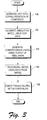
- the latter algorithm exhibits superior convergence properties resulting in faster training of the network while also yielding networks possessing better generalization capabilities compared to simple back propagation algorithms. It is desirable to utilize an architecture which is capable of representing a particular parameter map to a desired degree of accuracy while lending itself to automatic training procedures as explained and illustrated with reference to Figure 3.
- Block 100 represents the generation of test data during operation of a vehicle component, such as an engine.
- the test data provides representative values for a plurality of operating parameters for a particular set of operating conditions.
- this objective cannot be accomplished using conventional dynamometer testing alone because some engine parameters are not easily measured, and such a comprehensive map would be cost prohibitive.
- the present invention requires only enough test data to calibrate a physically-based simulation model as represented by block 102.
- test data generated in block 100 is used to calibrate the simulation model represented by block 102 at one or several representative "anchor" points.
- the simulation program can then be used to interpolate or extrapolate a more complete set of data as represented by block 104.
- This comprehensive map characterizes performance of the vehicle component as a function of predetermined design and control parameters.
- This information is then used to program or train the neural network-based virtual sensor as represented by block 106.
- the sensor is then embedded in the controller in the form of data and instructions as represented by block 108.
- the model-based mapping using established first principle parametric simulation models requires only about 1% of the experimental test data compared to the data required for a full empirical map. As such, the present invention has the potential for a two-thirds savings in cost while reducing the time required to generate a complete map from about a month to the order of a week.
- the present invention may be utilized to provide a virtual sensor for any of a number of operating parameters for various vehicle components to realize a "virtual" closed-loop control system.
- the present invention may be utilized to provide a virtual sensor for engine control systems which dynamically determine the residual mass fraction using various physically-based sensor inputs.
- the residual mass fraction refers to that fraction of the cylinder contents trapped in the current cycle which has been burned in some previous cycle. This may also be referred to as the burned gas fraction.
- RMF has both external and internal sources in conventional internal combustion engine operation.
- Exhaust gas recycling or recirculation (EGR) is the primary external source. EGR is introduced by routing some of the exhaust gases from the exhaust manifold back to the intake manifold via external plumbing. The amount of EGR introduced into the intake is regulated by an EGR valve at the point where the exhaust gases enter the intake manifold.
- the internal source (sometimes referred to as internal EGR) arises due to the inability of the gas exchange process in conventional engine designs to completely replace the burned gases with fresh air/fuel mixture.
- the amount of residual is influenced by the setting of the EGR valve, the throttle position, and the valve overlap, i.e. the period of time where both the intake and exhaust valves are open. Excessive dilution by residual from any source can degrade combustion quality. However, limited levels of residual under throttled operation have beneficial effects on emissions and fuel economy.
- EGR EGR
- the appropriate amount of EGR is generally determined experimentally by testing the engine at each condition on a dynamometer prior to installation in the vehicle. The engine controller is then programmed to supply the correct level of EGR as a function of engine speed and torque.
- variable valve timing mechanisms As practical in-vehicle devices, the level of internal EGR can be controlled by changing the opening and closing times of the intake and exhaust valves. This method of controlling RMF can either supplant or complement the external EGR system.
- a control strategy analogous to the EGR methodology could be devised for variable valve timing. One could find an optimal valve timing at each operating condition and program the resulting set into the engine controller.
- RMF is the fundamental engine parameter which is being controlled.
- the present invention may be utilized to develop a more robust control strategy since RMF may be dynamically determined and therefore controlled.
- RMF the value for a particular parameter
- traditional control techniques may be applied, i.e. comparing the measured value to the optimal, and adjusting either EGR or valve timing to correct any deviation.
- the cycle simulation program used according to the present invention calculates the thermodynamic state of the engine as a function of time, or crank angle, during the combustion cycle.
- the simulation tracks pressures, temperatures, and composition of the gases in the cylinder, intake system, and exhaust system by solving a set of differential equations.
- the engine can then be tested at all the relevant speed/torque combinations representative of its operating range.
- dilution RMF can be varied by changing EGR and/or valve timing as previously described.
- the cycle simulation program can be used to calculate the value of RMF as these parameters are varied to generate a comprehensive map.
- the optimal level of dilution is ascertained, the associated RMF is established as the target value for that speed and torque.
- the cycle simulation program can be used to calculate RMF as a function of all engine operating parameters (speed, torque, EGR, valve timing, spark advance, inlet temperature, etc.) These results can then be used to construct the virtual RMF sensor. If the virtual sensor is implemented through a neural net, these data comprise the training set by which the net learns the functional dependence of RMF on various other physical-based operating parameters. Of course, a virtual sensor according to the present invention may also use the outputs from various other virtual sensors as inputs.
- the controller interrogates the virtual sensor to determine the RMF associated with the current values for the operating parameters. This RMF value is compared to the previously determined optimal value for the current operating conditions as described above. If necessary, the controller can signal the actuator(s) controlling the appropriate parameter(s) e.g, valve timing to move RMF toward the optimal value.
Landscapes
- Engineering & Computer Science (AREA)
- Artificial Intelligence (AREA)
- Evolutionary Computation (AREA)
- Mechanical Engineering (AREA)
- General Engineering & Computer Science (AREA)
- Combustion & Propulsion (AREA)
- Chemical & Material Sciences (AREA)
- Health & Medical Sciences (AREA)
- Computer Vision & Pattern Recognition (AREA)
- Medical Informatics (AREA)
- Software Systems (AREA)
- Physics & Mathematics (AREA)
- General Physics & Mathematics (AREA)
- Automation & Control Theory (AREA)
- Combined Controls Of Internal Combustion Engines (AREA)
Description
- The present invention relates to virtual vehicle sensors which use neural networks trained using a simulation model to monitor a vehicle parameter.
- Modern engines utilise an electronic engine control module (ECM) to continuously monitor and control engine operation to optimize fuel economy, emissions control, and performance. The ECM uses various physical sensors to collect information reflecting current operating conditions. The information is used to generate output signals for various actuators which control operation of the engine. Using the actuators, the ECM controls the air-fuel ratio, fuel injection, ignition timing, and various other functions to control operation of the engine. Optimal control of the engine over a wide range of engine operating conditions (and ambient conditions) depends on the availability, accuracy, and reliability of data gathered by the engine sensors.
- An ideal engine control system would be capable of directly measuring each engine operating parameter which affects any control variable. However, any realizable design is subject to considerations such as the cost, durability, repairability, and/or technological feasibility (including packaging considerations) of appropriate sensors. The deployment of more and more physical sensors results in per-unit cost penalties in development and manufacturing. Replacement and repair costs also rise due to the increased number of sensors and difficulty in diagnosing sensor malfunctions. As such, actual systems typically involve design compromises to accommodate technological difficulties and reduce the cost and complexity of the physical system employed to monitor and control the engine. It is therefore desirable to improve the availability, accuracy, and reliability of data used to effect engine control without significantly impacting the cost, complexity, or repairability of the vehicle.
- US-A-5 539 638 describes a method of monitoring the operation of an internal combustion engine with a plurality of monitoring sensors. A predictive model processor is provided that uses model parameters stored in a memory to predict from the sensor inputs a predicted emissions output. The model is trained by means of a training database generated with inputs provided by the sensors and an actual emissions sensor output.
- The present invention uses one or more neural networks within the ECM which act as virtual sensing devices to replace or enhance traditional physical engine sensors.
- The present invention provides a method of manufacturing a sensor for use with a vehicle component having a controller in communication with a plurality of physical sensors each generating a signal indicative of first operating parameters, the sensor determining values for a second operating parameter based on values for the plurality of first operating parameters, the method comprising the steps of:
- monitoring signals generated by the plurality of physical sensors to generate test data representative of values for the first operating parameters for a first set of operating conditions; and
- embedding a trained neural network into the controller to determine values for the second operating parameter based on values for the plurality of first operating parameters; characterised in that the method further comprises;
- calibrating a simulator for simulating operation of the vehicle using the test data;
- generating at least one map which characterizes performance of the vehicle component as a function of predetermined parameters, the map being based on output of the simulator for a second set of operating conditions; and
- adjusting weights corresponding to nodes of the neural network based on the at least one map so as to train the neural network.
-
- Numerous advantages are associated with the present invention. For example, the present invention allows sensing of operating parameters which are currently difficult or cost-prohibitive to measure directly. The present invention utilizes simulation models to generate more comprehensive data representing more operating conditions than would be economically feasible using traditional testing and mapping. The comprehensive data results in more accurate training of the neural networks thereby leading to a more accurate sensor. The sensor may be used to provide monitoring of fundamental physical quantities characterizing operation of the vehicle components which are otherwise unavailable using physical sensors. The present invention is applicable to a wide variety of control systems although particularly suited for control of vehicle engines.
- The invention will now be described, by way of example, with reference to the accompanying drawings, in which:
- Figure 1 is a block diagram illustrating an engine control application utilizing one embodiment of the present invention;
- Figure 2 is a block diagram illustrating a virtual sensor based on a neural network structure according to the present invention; and
- Figure 3 is a flowchart illustrating a method for developing and manufacturing a virtual sensor according to the present invention.
-
- Referring now to Figure 1, a block diagram is shown illustrating one potential application for a virtual sensor according to the present invention. A
control system 10 includes a vehicle component such asengine 12 in communication with acontroller 14.System 10 includes a plurality of physical sensors, indicated generally byreference numeral 16. Any number ofphysical sensors 16 may be used depending upon the particular application and the particular vehicle component being controlled.Physical sensors 16 may include a mass air flow (MAF)sensor 18, a throttle position sensor (TPS) 20, an engine speed sensor (RPM) 22, and/or a coolant temperature (TMP)sensor 24. - In many gasoline-powered automotive applications,
engine 12 is coupled to acatalytic converter 26 via anexhaust pipe 28.Catalytic converter 26 is typically coupled to a muffler (not specifically illustrated) viaexhaust pipe 30. In these applications, additionalphysical sensors 16 may include an upstream exhaust gas oxygen (EGO)sensor 32, adownstream EGO sensor 34, and a catalyticconverter temperature sensor 36. Various other vehicle sensors may also be included, such as vehicle speed sensor (VSS) 38 and manifold absolute pressure (MAP)sensor 39. - In operation,
controller 14 monitors signals generated byphysical sensors 16 to determine values for the corresponding operating parameters ofengine 12. Signals generated byphysical sensors 16 are communicated to one ormore input ports 40. Appropriate signal conditioning, buffering, circuit protection, and signal conversion is typically provided by circuitry withincontroller 14. For example, a temperature signal generated bycoolant temperature sensor 24 may be filtered, buffered, and converted to a digital signal by the circuitry withincontroller 14 prior to passing throughinput ports 40. -
Controller 14 of Figure 1 preferably includes a microprocessor unit (MPU) 42 in communication with various computer-readable storage media, indicated generally byreference numeral 44. Computer-readable storage media 44 may include various types of volatile and non-volatile memory such as keep-alive memory (KAM) 46, read only memory (ROM) 48, and random access memory (RAM) 50. Computer-readable storage media 44 communicate withmicroprocessor 42 via address anddata bus 52.Microprocessor 42 processes values corresponding to various operating parameters as indicated by the signals received throughinput ports 40 in accordance with data and instructions stored in computer-readable media 44. -
Microprocessor 42 generates control and command signals which are communicated viaoutput ports 54 to various actuators, indicated generally byreference numeral 56. Actuators may include afuel controller 58 which provides appropriate signals for one or more fuel injectors (not specifically illustrated). Other actuators may include aspark controller 60 and an exhaust gas recirculation (EGR)valve 62. EGRvalve 62 is used to control the amount of exhaust gases routed fromexhaust 28 to intake 64 viaplumbing 66. - As also illustrated in Figure 1,
controller 14 includes a neural network-basedvirtual sensor 68 according to the present invention. The virtual sensor is preferably embedded withincontroller 14 and may exist across or within one or more computer-readable storage media 44. For example, various instructions may be stored in one type or one physical storage media while working data is stored in another physical device which may or may not be of the same type of storage media. -
Virtual sensor 68 may be used to determine a value for an engine operating parameter which is difficult or costly to measure directly. Values for various physical-based parameters are input tovirtual sensor 68, such as those values which represent the physical signals generated byphysical sensors 16. Various other signals may provide input tovirtual sensor 68 to dynamically determine values for various engine operating parameters. Such signals may be indicative of air/fuel ratio, cam timing, air charge temperature, oil temperature, and the like.Virtual sensor 68 forms a linear combination of non-linear functions of physically-based parameters.Virtual sensor 68 then determines values for various other engine operating parameters which are difficult to measure. Such parameters may include residual mass fraction, emissions, knock index, peak pressure rise rate, exhaust gas temperature, and exhaust gas oxygen content. The output from one or more virtual sensors enablescontroller 14 to better account for the internal processes ofengine 12. This information may be used to improve control ofengine 12 by adjusting various functions such as spark timing, EGR level, fuel injection timing, cam timing, or fuel pulsewidth to minimize fuel consumption, emissions, knock tendency, engine instability, and noise, vibration, and harshness (NVH) effects. As such, the present invention improves engine control by providing information representing dynamic engine state conditions based on various non-linear relationships among physical-based signals. The non-linear relationships are captured automatically by the neural network during training, as described in greater detail herein. - Referring now to Figure 2, a block diagram illustrating a neural network structure for a virtual sensor according to the present invention is shown.
Virtual sensor 68 includesvarious inputs 80 generated by physical sensors and/or other virtual sensors. Aninput layer 82 includesnodes 84 associated with each of theinputs 80. The neural network-basedsensor 68 also includes one or morehidden layers 86 and an output layer 88.Nodes 84 ofinput layer 82 communicate with one ormore nodes 90 of hiddenlayers 86 viaconnections 92. During training of the network, the various connections along with associated weights are determined.Block 94 represents a polynomial function of its inputs to generate asensor output 96. The degree of the polynomial employed inblock 94 is constrained to be one less than the number of nodes in output layer 88. For most virtual sensors, a feed-forward neural network will provide satisfactory performance. It should be recognized, however, that the number and structure of nodes for each layer will vary depending upon the particular parameter being determined. - The particular structure illustrated in Figure 2 depicts a neural network for a set of engine performance variables using knowledge that most of the variables are low-order polynomial functions of the spark input when all the other parameters are fixed. Instead of predicting the output directly, the neural network of Figure 2 predicts the polynomial coefficients represented by
block 94 as functions of the other engine operating parameters. It should be noted that this type of neural-regression model is not restricted to the use of polynomials as any functional module may be employed which allows determination of the partial derivatives of the module's output with respect to the neural network's weights to be computed. - Indeed, the choice of non-polynomial functions is often preferred because of the tendency of interpolating polynomials to exhibit large errors when used to extrapolate outside the bounds of the underlying data.
- Once a particular network structure or model is determined, the training of the network or the adjustment of the weights associated with each of the
connections 92 between nodes or neurons can be carried out using established algorithms, such as the Levenburg-Marquardt algorithm or the Node Decoupled Extended Kalman filter algorithm developed by Puskorius and Feldkamp. For some engine control applications, the latter algorithm exhibits superior convergence properties resulting in faster training of the network while also yielding networks possessing better generalization capabilities compared to simple back propagation algorithms. It is desirable to utilize an architecture which is capable of representing a particular parameter map to a desired degree of accuracy while lending itself to automatic training procedures as explained and illustrated with reference to Figure 3. - Referring now to Figure 3, a flowchart illustrating a method for manufacturing or developing neural network-based virtual sensors is shown.
Block 100 represents the generation of test data during operation of a vehicle component, such as an engine. The test data provides representative values for a plurality of operating parameters for a particular set of operating conditions. To capture the relationship among the various inputs over all the operating conditions, it is desirable to generate a large set of data which reflects the typically non-linear relationship among basic engine operating parameters and the desired sensor output. Typically, this objective cannot be accomplished using conventional dynamometer testing alone because some engine parameters are not easily measured, and such a comprehensive map would be cost prohibitive. As such, the present invention requires only enough test data to calibrate a physically-based simulation model as represented byblock 102. - Preferably, test data generated in
block 100 is used to calibrate the simulation model represented byblock 102 at one or several representative "anchor" points. The simulation program can then be used to interpolate or extrapolate a more complete set of data as represented byblock 104. This comprehensive map characterizes performance of the vehicle component as a function of predetermined design and control parameters. This information is then used to program or train the neural network-based virtual sensor as represented byblock 106. The sensor is then embedded in the controller in the form of data and instructions as represented byblock 108. - The model-based mapping using established first principle parametric simulation models requires only about 1% of the experimental test data compared to the data required for a full empirical map. As such, the present invention has the potential for a two-thirds savings in cost while reducing the time required to generate a complete map from about a month to the order of a week.
- As described above, the present invention may be utilized to provide a virtual sensor for any of a number of operating parameters for various vehicle components to realize a "virtual" closed-loop control system. As an example, the present invention may be utilized to provide a virtual sensor for engine control systems which dynamically determine the residual mass fraction using various physically-based sensor inputs.
- The residual mass fraction (RMF), as used herein, refers to that fraction of the cylinder contents trapped in the current cycle which has been burned in some previous cycle. This may also be referred to as the burned gas fraction. RMF has both external and internal sources in conventional internal combustion engine operation. Exhaust gas recycling or recirculation (EGR) is the primary external source. EGR is introduced by routing some of the exhaust gases from the exhaust manifold back to the intake manifold via external plumbing. The amount of EGR introduced into the intake is regulated by an EGR valve at the point where the exhaust gases enter the intake manifold. The internal source (sometimes referred to as internal EGR) arises due to the inability of the gas exchange process in conventional engine designs to completely replace the burned gases with fresh air/fuel mixture. The amount of residual is influenced by the setting of the EGR valve, the throttle position, and the valve overlap, i.e. the period of time where both the intake and exhaust valves are open. Excessive dilution by residual from any source can degrade combustion quality. However, limited levels of residual under throttled operation have beneficial effects on emissions and fuel economy.
- As RMF increases, it displaces fresh charge. In order to trap the fuel and air required to maintain the required level of engine torque output, the throttle must be opened up so that more total gases become trapped in the combustion chamber. The heat liberated by the combustion is distributed over a larger mass, thus lowering peak temperatures during combustion. Production of oxides of nitrogen (NOx), being very sensitive to combustion temperature, is thereby reduced significantly. Opening up the throttle valve also increases the intake pressure which reduces throttling losses and improves fuel economy.
- It is common practice to use EGR to control the level of RMF to maximize fuel economy and minimize NOx emissions at each speed and torque throughout the operating range of the engine. The appropriate amount of EGR is generally determined experimentally by testing the engine at each condition on a dynamometer prior to installation in the vehicle. The engine controller is then programmed to supply the correct level of EGR as a function of engine speed and torque.
- With the advent of variable valve timing mechanisms as practical in-vehicle devices, the level of internal EGR can be controlled by changing the opening and closing times of the intake and exhaust valves. This method of controlling RMF can either supplant or complement the external EGR system. A control strategy analogous to the EGR methodology could be devised for variable valve timing. One could find an optimal valve timing at each operating condition and program the resulting set into the engine controller.
- In either case, RMF is the fundamental engine parameter which is being controlled. The present invention may be utilized to develop a more robust control strategy since RMF may be dynamically determined and therefore controlled. Once the value for a particular parameter (RMF in this case) can be directly determined, traditional control techniques may be applied, i.e. comparing the measured value to the optimal, and adjusting either EGR or valve timing to correct any deviation.
- The cycle simulation program used according to the present invention calculates the thermodynamic state of the engine as a function of time, or crank angle, during the combustion cycle. The simulation tracks pressures, temperatures, and composition of the gases in the cylinder, intake system, and exhaust system by solving a set of differential equations. The composition of the cylinder is governed by the conservation equations for total mass and fresh charge fraction:

- m
- represents the total mass in the cylinder,
- c
- represents the mass fraction of fresh charge in the cylinder,
- r
- represents the RMF in the cylinder,
- m ˙i
- represents the mass flow rate into the cylinder through the intake valve(s),
- m ˙e
- represents the mass flow rate out of the cylinder through the exhaust valve(s),
-

- represents the charge fraction associated with m ˙i (c if m ˙i < 0, ci if m ˙i > 0),
-

- represents the charge fraction associated with m ˙e (c if m ˙e > 0, ce if m ˙e < 0,
- ci
- represents charge fraction of gas residing in the intake port, and
- ce
- represents charge fraction of gas residing in the exhaust port.
- The engine can then be tested at all the relevant speed/torque combinations representative of its operating range. At each point, dilution RMF can be varied by changing EGR and/or valve timing as previously described. The cycle simulation program can be used to calculate the value of RMF as these parameters are varied to generate a comprehensive map. When the optimal level of dilution is ascertained, the associated RMF is established as the target value for that speed and torque.
- Meanwhile, the cycle simulation program can be used to calculate RMF as a function of all engine operating parameters (speed, torque, EGR, valve timing, spark advance, inlet temperature, etc.) These results can then be used to construct the virtual RMF sensor. If the virtual sensor is implemented through a neural net, these data comprise the training set by which the net learns the functional dependence of RMF on various other physical-based operating parameters. Of course, a virtual sensor according to the present invention may also use the outputs from various other virtual sensors as inputs.
- During operation in the vehicle, the controller interrogates the virtual sensor to determine the RMF associated with the current values for the operating parameters. This RMF value is compared to the previously determined optimal value for the current operating conditions as described above. If necessary, the controller can signal the actuator(s) controlling the appropriate parameter(s) e.g, valve timing to move RMF toward the optimal value.
Claims (7)
- A method of manufacturing a sensor (68) for use with a vehicle component (12) having a controller (14) in communication with a plurality of physical sensors (16) each generating a signal indicative of first operating parameters, the sensor (68) determining values for a second operating parameter based on values for the plurality of first operating parameters, the method comprising the steps of:characterised in that the method further comprises;monitoring (100) signals generated by the plurality of physical sensors (16) to generate test data representative of values for the first operating parameters for a first set of operating conditions; andembedding (108) a trained neural network into the controller (14) to determine values for the second operating parameter based on values for the plurality of first operating parameters;calibrating (102) a simulator for simulating operation of the vehicle using the test data;generating (104) at least one map which characterizes performance of the vehicle component as a function of predetermined parameters, the map being based on output of the simulator for a second set of operating conditions; andadjusting (106) weights corresponding to nodes of the neural network based on the at least one map so as to train the neural network.
- A method as claimed in claim 1, wherein the vehicle component comprises an engine (12) and wherein the step (100) of monitoring signals generated by the plurality of physical sensors to generate test data representative of values for the first operating parameters for a first set of operating conditions comprises operating the engine (12) on a dynamometer.
- A method as claimed in claim 1 or 2, wherein the step (108) of embedding a trained neural network into the controller comprises storing a representation of the trained neural network in computer readable media (44), the representation including a plurality of instructions executable by a microprocessor (42) and data representing the weights corresponding to the nodes of the neural network.
- A method as claimed in claim 1, 2 or 3, wherein the step (106) of adjusting weights corresponding to nodes of the neural network comprises adjusting weights corresponding to monotonically increasing piecewise differentiable function nodes of the neural network.
- A method as claimed in claim 1, 2, 3 or 4, further comprising the steps of;processing the values for the first operating parameters using the trained neural network to determine a value for the second operating parameter; andcontrolling the vehicle component based on the value of the second operating parameter.
- A method as claimed in claim 5, wherein the step of processing the values for the first operating parameters using the trained neural network to determine a value for the second operating parameter comprises determining polynomial coefficients for the second operating parameter, the coefficients being functions of the first plurality of operating parameters.
- A method as claimed in claim 5 or 6, wherein the step of processing the values for the first operating parameters using the trained neural network to determine a value for the second operating parameter is employed in relation to a second operating parameter lacking a physical sensor for directly providing values indicative of current operating conditions.
Applications Claiming Priority (2)
| Application Number | Priority Date | Filing Date | Title |
|---|---|---|---|
| US852829 | 1997-05-07 | ||
| US08/852,829 US6236908B1 (en) | 1997-05-07 | 1997-05-07 | Virtual vehicle sensors based on neural networks trained using data generated by simulation models |
Publications (2)
| Publication Number | Publication Date |
|---|---|
| EP0877309A1 EP0877309A1 (en) | 1998-11-11 |
| EP0877309B1 true EP0877309B1 (en) | 2000-06-21 |
Family
ID=25314327
Family Applications (1)
| Application Number | Title | Priority Date | Filing Date |
|---|---|---|---|
| EP98303453A Expired - Lifetime EP0877309B1 (en) | 1997-05-07 | 1998-05-01 | Virtual vehicle sensors based on neural networks trained using data generated by simulation models |
Country Status (3)
| Country | Link |
|---|---|
| US (1) | US6236908B1 (en) |
| EP (1) | EP0877309B1 (en) |
| DE (1) | DE69800186T2 (en) |
Cited By (15)
| Publication number | Priority date | Publication date | Assignee | Title |
|---|---|---|---|---|
| DE10203919A1 (en) * | 2002-01-31 | 2003-08-21 | Bayerische Motoren Werke Ag | Reconstructing physical magnitudes for further processing in association with engine controller using neural network, produces models for individual system sections |
| WO2005028837A3 (en) * | 2003-09-23 | 2005-06-02 | Westport Res Inc | Method for controlling combustion in an internal combustion engine and predicting performance and emissions |
| AT500978B1 (en) * | 2003-05-13 | 2006-05-15 | Avl List Gmbh | METHOD FOR OPTIMIZING VEHICLES |
| WO2007020456A3 (en) * | 2005-08-19 | 2007-08-16 | Axeon Ltd | Neural network method and apparatus |
| DE102014000397A1 (en) | 2014-01-17 | 2015-07-23 | Fev Gmbh | Model-based cylinder fill detection for an internal combustion engine |
| US10036338B2 (en) | 2016-04-26 | 2018-07-31 | Honeywell International Inc. | Condition-based powertrain control system |
| US10124750B2 (en) | 2016-04-26 | 2018-11-13 | Honeywell International Inc. | Vehicle security module system |
| US10235479B2 (en) | 2015-05-06 | 2019-03-19 | Garrett Transportation I Inc. | Identification approach for internal combustion engine mean value models |
| US10272779B2 (en) | 2015-08-05 | 2019-04-30 | Garrett Transportation I Inc. | System and approach for dynamic vehicle speed optimization |
| US10309287B2 (en) | 2016-11-29 | 2019-06-04 | Garrett Transportation I Inc. | Inferential sensor |
| US10309281B2 (en) | 2011-09-19 | 2019-06-04 | Garrett Transportation I Inc. | Coordinated engine and emissions control system |
| US10423131B2 (en) | 2015-07-31 | 2019-09-24 | Garrett Transportation I Inc. | Quadratic program solver for MPC using variable ordering |
| US10474964B2 (en) | 2016-01-26 | 2019-11-12 | Ford Global Technologies, Llc | Training algorithm for collision avoidance |
| US11057213B2 (en) | 2017-10-13 | 2021-07-06 | Garrett Transportation I, Inc. | Authentication system for electronic control unit on a bus |
| US11156180B2 (en) | 2011-11-04 | 2021-10-26 | Garrett Transportation I, Inc. | Integrated optimization and control of an engine and aftertreatment system |
Families Citing this family (107)
| Publication number | Priority date | Publication date | Assignee | Title |
|---|---|---|---|---|
| US6594602B1 (en) * | 1999-04-23 | 2003-07-15 | Halliburton Energy Services, Inc. | Methods of calibrating pressure and temperature transducers and associated apparatus |
| US6761077B1 (en) | 1999-08-25 | 2004-07-13 | Faurecia Exhaust Systems, Inc. | Dual mast system for simulation testing |
| DE10010681A1 (en) * | 2000-03-04 | 2001-09-06 | Heinz J Theuerkauf | Simulating signal from electronic sensor in motor vehicle using virtual sensor in vehicle control device, based on neural network model |
| US6957172B2 (en) * | 2000-03-09 | 2005-10-18 | Smartsignal Corporation | Complex signal decomposition and modeling |
| EP1306511B1 (en) | 2000-07-27 | 2004-12-29 | Lear Automotive (EEDS) Spain, S.L. | System and method for optimizing the control program of a window-lifting device with anti-jam protection |
| US6556939B1 (en) * | 2000-11-22 | 2003-04-29 | Smartsignal Corporation | Inferential signal generator for instrumented equipment and processes |
| US6493689B2 (en) * | 2000-12-29 | 2002-12-10 | General Dynamics Advanced Technology Systems, Inc. | Neural net controller for noise and vibration reduction |
| US6789620B2 (en) | 2001-02-16 | 2004-09-14 | Halliburton Energy Services, Inc. | Downhole sensing and flow control utilizing neural networks |
| GB2379513B (en) * | 2001-02-16 | 2005-06-29 | Halliburton Energy Serv Inc | Downhole sensing and flow control utilizing neural networks |
| JP4686909B2 (en) * | 2001-06-07 | 2011-05-25 | 株式会社アドヴィックス | Sensor abnormality detection method |
| US6687601B2 (en) | 2002-03-21 | 2004-02-03 | Cummins, Inc. | System for diagnosing an air handling mechanism of an internal combustion engine |
| US6697729B2 (en) | 2002-04-08 | 2004-02-24 | Cummins, Inc. | System for estimating NOx content of exhaust gas produced by an internal combustion engine |
| US6882929B2 (en) * | 2002-05-15 | 2005-04-19 | Caterpillar Inc | NOx emission-control system using a virtual sensor |
| US6785604B2 (en) | 2002-05-15 | 2004-08-31 | Caterpillar Inc | Diagnostic systems for turbocharged engines |
| US7035834B2 (en) * | 2002-05-15 | 2006-04-25 | Caterpillar Inc. | Engine control system using a cascaded neural network |
| US7053787B2 (en) * | 2002-07-02 | 2006-05-30 | Halliburton Energy Services, Inc. | Slickline signal filtering apparatus and methods |
| US20050137995A1 (en) * | 2002-08-16 | 2005-06-23 | Powitec Intelligent Technologies Gmbh | Method for regulating a thermodynamic process by means of neural networks |
| EP1416143A1 (en) * | 2002-10-29 | 2004-05-06 | STMicroelectronics S.r.l. | Virtual sensor for the exhaust emissions of an endothermic motor and corresponding injection control system |
| US6772099B2 (en) * | 2003-01-08 | 2004-08-03 | Dell Products L.P. | System and method for interpreting sensor data utilizing virtual sensors |
| US6925376B2 (en) * | 2003-04-01 | 2005-08-02 | Cummins, Inc. | System for diagnosing operation of a cooling system for an internal combustion engine |
| US6850833B1 (en) | 2003-11-03 | 2005-02-01 | Cummins, Inc. | System for diagnosing delta pressure sensor operation |
| FR2862342B1 (en) * | 2003-11-19 | 2006-02-17 | Renault Sas | METHOD AND SYSTEM FOR ESTIMATING QUANTITIES OF PARTICLES EMITTED IN EXHAUST GASES OF A DIESEL ENGINE OF A MOTOR VEHICLE |
| JP2007533911A (en) * | 2004-04-20 | 2007-11-22 | サウスウエスト リサーチ インスティテュート | Virtual cylinder pressure sensor with individual estimators for pressure related values |
| DE112005001710B4 (en) | 2004-07-22 | 2019-10-10 | Avl List Gmbh | Method for investigating the behavior of complex systems, in particular of internal combustion engines |
| JP4376799B2 (en) * | 2005-01-19 | 2009-12-02 | 株式会社日立製作所 | Ignition timing control device for internal combustion engine |
| EP2275946A1 (en) * | 2005-03-04 | 2011-01-19 | STMicroelectronics S.r.l. | Probabilistic neural network and relative training method |
| US20060229753A1 (en) * | 2005-04-08 | 2006-10-12 | Caterpillar Inc. | Probabilistic modeling system for product design |
| US7877239B2 (en) * | 2005-04-08 | 2011-01-25 | Caterpillar Inc | Symmetric random scatter process for probabilistic modeling system for product design |
| US20060230097A1 (en) * | 2005-04-08 | 2006-10-12 | Caterpillar Inc. | Process model monitoring method and system |
| US8364610B2 (en) | 2005-04-08 | 2013-01-29 | Caterpillar Inc. | Process modeling and optimization method and system |
| US20060229852A1 (en) * | 2005-04-08 | 2006-10-12 | Caterpillar Inc. | Zeta statistic process method and system |
| US7565333B2 (en) * | 2005-04-08 | 2009-07-21 | Caterpillar Inc. | Control system and method |
| US8209156B2 (en) * | 2005-04-08 | 2012-06-26 | Caterpillar Inc. | Asymmetric random scatter process for probabilistic modeling system for product design |
| US20070061144A1 (en) * | 2005-08-30 | 2007-03-15 | Caterpillar Inc. | Batch statistics process model method and system |
| US7765029B2 (en) * | 2005-09-13 | 2010-07-27 | Neurosciences Research Foundation, Inc. | Hybrid control device |
| US7487134B2 (en) * | 2005-10-25 | 2009-02-03 | Caterpillar Inc. | Medical risk stratifying method and system |
| US7499842B2 (en) | 2005-11-18 | 2009-03-03 | Caterpillar Inc. | Process model based virtual sensor and method |
| US20070118487A1 (en) * | 2005-11-18 | 2007-05-24 | Caterpillar Inc. | Product cost modeling method and system |
| DE102006054425A1 (en) * | 2005-11-22 | 2007-05-31 | Continental Teves Ag & Co. Ohg | Method for determination of value of model parameter of reference vehicle model, involves determination of statistical value of model parameter whereby artificial neural network is adapted with learning procedure |
| FR2893982A1 (en) * | 2005-11-25 | 2007-06-01 | Renault Sas | METHOD AND SYSTEM FOR ESTIMATING EXHAUST GAS TEMPERATURE INTERNALLY FROM A POST PROCESSING SYSTEM |
| FR2893983B1 (en) * | 2005-11-29 | 2011-03-25 | Renault Sas | METHOD AND SYSTEM FOR ESTIMATING EXHAUST GAS TEMPERATURE AND INTERNAL COMBUSTION ENGINE EQUIPPED WITH SUCH A SYSTEM |
| US7233855B1 (en) * | 2005-12-08 | 2007-06-19 | Gm Global Technology Operations, Inc. | Apparatus and method for comparing the fuel consumption of an alternative fuel vehicle with that of a traditionally fueled comparison vehicle |
| US7953521B2 (en) * | 2005-12-30 | 2011-05-31 | Microsoft Corporation | Learning controller for vehicle control |
| US7505949B2 (en) * | 2006-01-31 | 2009-03-17 | Caterpillar Inc. | Process model error correction method and system |
| US20070203810A1 (en) * | 2006-02-13 | 2007-08-30 | Caterpillar Inc. | Supply chain modeling method and system |
| CA2538984C (en) * | 2006-03-10 | 2007-11-06 | Westport Research Inc. | Method of accurately metering a gaseous fuel that is injected directly into a combustion chamber of an internal combustion engine |
| US8275577B2 (en) | 2006-09-19 | 2012-09-25 | Smartsignal Corporation | Kernel-based method for detecting boiler tube leaks |
| US8478506B2 (en) * | 2006-09-29 | 2013-07-02 | Caterpillar Inc. | Virtual sensor based engine control system and method |
| US8311774B2 (en) | 2006-12-15 | 2012-11-13 | Smartsignal Corporation | Robust distance measures for on-line monitoring |
| US7588368B2 (en) * | 2006-12-20 | 2009-09-15 | Cummins Inc. | System for diagnosing temperature sensor operation in an exhaust gas aftertreatment system |
| US7680586B2 (en) * | 2006-12-20 | 2010-03-16 | Cummins Inc. | Mass air flow sensor signal compensation system |
| US7483774B2 (en) * | 2006-12-21 | 2009-01-27 | Caterpillar Inc. | Method and system for intelligent maintenance |
| US20080154811A1 (en) * | 2006-12-21 | 2008-06-26 | Caterpillar Inc. | Method and system for verifying virtual sensors |
| US8315302B2 (en) * | 2007-05-31 | 2012-11-20 | Infineon Technologies Ag | Pulse width modulator using interpolator |
| US7787969B2 (en) * | 2007-06-15 | 2010-08-31 | Caterpillar Inc | Virtual sensor system and method |
| US7831416B2 (en) * | 2007-07-17 | 2010-11-09 | Caterpillar Inc | Probabilistic modeling system for product design |
| US7788070B2 (en) * | 2007-07-30 | 2010-08-31 | Caterpillar Inc. | Product design optimization method and system |
| WO2009025561A1 (en) * | 2007-08-17 | 2009-02-26 | Institutt For Energiteknikk | System and method for empirical ensemble-based virtual sensing |
| US7542879B2 (en) * | 2007-08-31 | 2009-06-02 | Caterpillar Inc. | Virtual sensor based control system and method |
| US7593804B2 (en) * | 2007-10-31 | 2009-09-22 | Caterpillar Inc. | Fixed-point virtual sensor control system and method |
| US8036764B2 (en) | 2007-11-02 | 2011-10-11 | Caterpillar Inc. | Virtual sensor network (VSN) system and method |
| US8224468B2 (en) * | 2007-11-02 | 2012-07-17 | Caterpillar Inc. | Calibration certificate for virtual sensor network (VSN) |
| DE602008001660D1 (en) | 2008-01-29 | 2010-08-12 | Honda Motor Co Ltd | Control system for an internal combustion engine |
| DE602008001659D1 (en) | 2008-01-29 | 2010-08-12 | Honda Motor Co Ltd | Control system for an internal combustion engine |
| GB2490818B (en) * | 2008-05-19 | 2013-07-17 | Ford Global Tech Llc | A Method of Producing a Pair of Virtual Sensors for an Engine |
| US20090293457A1 (en) * | 2008-05-30 | 2009-12-03 | Grichnik Anthony J | System and method for controlling NOx reactant supply |
| US8086640B2 (en) * | 2008-05-30 | 2011-12-27 | Caterpillar Inc. | System and method for improving data coverage in modeling systems |
| US7917333B2 (en) * | 2008-08-20 | 2011-03-29 | Caterpillar Inc. | Virtual sensor network (VSN) based control system and method |
| US8510088B2 (en) * | 2008-09-30 | 2013-08-13 | Uchicago Argonne Llc | Flexible evaluator for vehicle propulsion systems |
| US8400323B2 (en) * | 2009-12-21 | 2013-03-19 | Delphi Technologies, Inc. | Capacitive occupant sensing system and method |
| US8793004B2 (en) | 2011-06-15 | 2014-07-29 | Caterpillar Inc. | Virtual sensor system and method for generating output parameters |
| US8812914B2 (en) * | 2011-10-24 | 2014-08-19 | Fisher Controls International, Llc | Field control devices having pre-defined error-states and related methods |
| US9650934B2 (en) | 2011-11-04 | 2017-05-16 | Honeywell spol.s.r.o. | Engine and aftertreatment optimization system |
| US9328698B2 (en) | 2013-05-14 | 2016-05-03 | Ford Global Technologies, Llc | Automotive virtual humidity sensor |
| US11948703B2 (en) | 2019-04-01 | 2024-04-02 | Anya L. Getman | Methods and devices for electrically insulating a power line |
| US9483038B2 (en) * | 2014-04-03 | 2016-11-01 | Rockwell Automation Technologies, Inc. | System for generating or modifying cams |
| WO2016057287A1 (en) * | 2014-10-06 | 2016-04-14 | Ptc Inc. | Virtual sensors supported by a computer aided design (cad) model and software |
| US11136932B2 (en) | 2014-12-17 | 2021-10-05 | Cummins Inc. | Charge-flow adjustment in closed-loop exhaust temperature control on dual fuel engines |
| EP3051367B1 (en) | 2015-01-28 | 2020-11-25 | Honeywell spol s.r.o. | An approach and system for handling constraints for measured disturbances with uncertain preview |
| EP3056706A1 (en) | 2015-02-16 | 2016-08-17 | Honeywell International Inc. | An approach for aftertreatment system modeling and model identification |
| US10853104B2 (en) * | 2015-02-27 | 2020-12-01 | Plasma Business Intelligence, Inc. | Virtual environment for simulating a real-world environment with a large number of virtual and real connected devices |
| US10047686B2 (en) * | 2015-07-31 | 2018-08-14 | GM Global Technology Operations LLC | Physics based single cylinder charging model |
| US9740944B2 (en) * | 2015-12-18 | 2017-08-22 | Ford Global Technologies, Llc | Virtual sensor data generation for wheel stop detection |
| US10415492B2 (en) | 2016-01-29 | 2019-09-17 | Garrett Transportation I Inc. | Engine system with inferential sensor |
| US9803576B2 (en) | 2016-02-16 | 2017-10-31 | Robert Bosch Gmbh | System and method to predict calibration values based on existing calibrations |
| US10055675B2 (en) * | 2016-06-15 | 2018-08-21 | Ford Global Technologies, Llc | Training algorithm for collision avoidance using auditory data |
| US11210436B2 (en) * | 2016-07-07 | 2021-12-28 | Ford Global Technologies, Llc | Virtual sensor-data-generation system and method supporting development of algorithms facilitating navigation of railway crossings in varying weather conditions |
| US10210451B2 (en) * | 2016-07-22 | 2019-02-19 | Alpine Electronics of Silicon Valley, Inc. | Neural network applications in resource constrained environments |
| US10323942B2 (en) * | 2016-09-23 | 2019-06-18 | Qualcomm Incorporated | User-specific learning for improved pedestrian motion modeling in a mobile device |
| US10388005B2 (en) | 2017-08-11 | 2019-08-20 | United Technologies Corporation | Sensor system for data enhancement |
| US10387803B2 (en) | 2017-08-11 | 2019-08-20 | United Technologies Corporation | Sensor system for transcoding data |
| JP6501018B1 (en) * | 2018-04-20 | 2019-04-17 | トヨタ自動車株式会社 | Machine learning device for unburned fuel |
| ES2852401T3 (en) | 2018-07-06 | 2021-09-13 | Siemens Ag | Positioning method, device and system for positioning a sensor |
| JP7043030B2 (en) * | 2018-08-01 | 2022-03-29 | オムロン株式会社 | Photoelectric sensor |
| US11714388B1 (en) | 2018-08-10 | 2023-08-01 | Apple Inc. | Conditional error models |
| US11051230B2 (en) | 2018-08-22 | 2021-06-29 | Bae Systems Information And Electronic Systems Integration Inc. | Wireless resilient routing reconfiguration linear program |
| JP6702389B2 (en) * | 2018-10-09 | 2020-06-03 | トヨタ自動車株式会社 | Vehicle drive control device, vehicle-mounted electronic control unit, learned model, machine learning system, vehicle drive control method, electronic control unit manufacturing method, and output parameter calculation device |
| US10788396B2 (en) * | 2018-12-19 | 2020-09-29 | Fca Us Llc | Using an artificial neural network for combustion phasing control in a spark ignited internal combustion engine |
| DE102019107209B4 (en) * | 2019-03-21 | 2024-02-15 | Dr. Ing. H.C. F. Porsche Aktiengesellschaft | Sorting storage device and method for operating a sorting storage device |
| US11526724B2 (en) * | 2019-08-21 | 2022-12-13 | GM Global Technology Operations LLC | Virtual sensor for estimating online unmeasurable variables via successive time derivatives |
| CN114599870A (en) * | 2019-10-25 | 2022-06-07 | 沃尔沃卡车集团 | System and method for virtual turbocharger speed sensor using neural network |
| KR102165878B1 (en) * | 2020-01-20 | 2020-10-14 | 주식회사 현대케피코 | Method for Estimation of Engine Torque by Artificial Neural Network |
| US11459962B2 (en) * | 2020-03-02 | 2022-10-04 | Sparkcognitton, Inc. | Electronic valve control |
| US20220034753A1 (en) * | 2020-07-31 | 2022-02-03 | SparkCognition, Inc. | Calibration of offline real-world systems using simulations |
| WO2022238082A1 (en) * | 2021-05-10 | 2022-11-17 | Vitesco Technologies GmbH | Computer-implemented method and control device for controlling a drive train of a vehicle by means of a convolutional neural network |
| US20230153623A1 (en) * | 2021-11-18 | 2023-05-18 | GM Global Technology Operations LLC | Adaptively pruning neural network systems |
| DE102023207816A1 (en) * | 2023-08-15 | 2025-02-20 | Robert Bosch Gesellschaft mit beschränkter Haftung | Method for evaluating a data set with respect to suitability for determining a calculation function of a virtual sensor |
Family Cites Families (12)
| Publication number | Priority date | Publication date | Assignee | Title |
|---|---|---|---|---|
| JP2792633B2 (en) | 1990-02-09 | 1998-09-03 | 株式会社日立製作所 | Control device |
| US5274714A (en) * | 1990-06-04 | 1993-12-28 | Neuristics, Inc. | Method and apparatus for determining and organizing feature vectors for neural network recognition |
| US5212765A (en) * | 1990-08-03 | 1993-05-18 | E. I. Du Pont De Nemours & Co., Inc. | On-line training neural network system for process control |
| US5130936A (en) * | 1990-09-14 | 1992-07-14 | Arinc Research Corporation | Method and apparatus for diagnostic testing including a neural network for determining testing sufficiency |
| US5313407A (en) * | 1992-06-03 | 1994-05-17 | Ford Motor Company | Integrated active vibration cancellation and machine diagnostic system |
| US5539638A (en) | 1993-08-05 | 1996-07-23 | Pavilion Technologies, Inc. | Virtual emissions monitor for automobile |
| US5386373A (en) * | 1993-08-05 | 1995-01-31 | Pavilion Technologies, Inc. | Virtual continuous emission monitoring system with sensor validation |
| US5583964A (en) | 1994-05-02 | 1996-12-10 | Motorola, Inc. | Computer utilizing neural network and method of using same |
| US5625750A (en) * | 1994-06-29 | 1997-04-29 | Ford Motor Company | Catalyst monitor with direct prediction of hydrocarbon conversion efficiency by dynamic neural networks |
| US5559285A (en) * | 1994-12-05 | 1996-09-24 | Ford Motor Company | Fuzzy logic method for detecting misfiers in internal combustion engines |
| US5745653A (en) * | 1996-02-05 | 1998-04-28 | Ford Global Technologies, Inc. | Generic neural network training and processing system |
| US5781700A (en) * | 1996-02-05 | 1998-07-14 | Ford Global Technologies, Inc. | Trained Neural network air/fuel control system |
-
1997
- 1997-05-07 US US08/852,829 patent/US6236908B1/en not_active Expired - Fee Related
-
1998
- 1998-05-01 EP EP98303453A patent/EP0877309B1/en not_active Expired - Lifetime
- 1998-05-01 DE DE69800186T patent/DE69800186T2/en not_active Expired - Fee Related
Cited By (20)
| Publication number | Priority date | Publication date | Assignee | Title |
|---|---|---|---|---|
| DE10203919A1 (en) * | 2002-01-31 | 2003-08-21 | Bayerische Motoren Werke Ag | Reconstructing physical magnitudes for further processing in association with engine controller using neural network, produces models for individual system sections |
| AT500978B1 (en) * | 2003-05-13 | 2006-05-15 | Avl List Gmbh | METHOD FOR OPTIMIZING VEHICLES |
| WO2005028837A3 (en) * | 2003-09-23 | 2005-06-02 | Westport Res Inc | Method for controlling combustion in an internal combustion engine and predicting performance and emissions |
| WO2007020456A3 (en) * | 2005-08-19 | 2007-08-16 | Axeon Ltd | Neural network method and apparatus |
| US10309281B2 (en) | 2011-09-19 | 2019-06-04 | Garrett Transportation I Inc. | Coordinated engine and emissions control system |
| US11619189B2 (en) | 2011-11-04 | 2023-04-04 | Garrett Transportation I Inc. | Integrated optimization and control of an engine and aftertreatment system |
| US11156180B2 (en) | 2011-11-04 | 2021-10-26 | Garrett Transportation I, Inc. | Integrated optimization and control of an engine and aftertreatment system |
| DE102014000397A1 (en) | 2014-01-17 | 2015-07-23 | Fev Gmbh | Model-based cylinder fill detection for an internal combustion engine |
| US10533510B2 (en) | 2014-01-17 | 2020-01-14 | Fev Gmbh | Model-based cylinder charge detection for an internal combustion engine |
| US10235479B2 (en) | 2015-05-06 | 2019-03-19 | Garrett Transportation I Inc. | Identification approach for internal combustion engine mean value models |
| US11144017B2 (en) | 2015-07-31 | 2021-10-12 | Garrett Transportation I, Inc. | Quadratic program solver for MPC using variable ordering |
| US10423131B2 (en) | 2015-07-31 | 2019-09-24 | Garrett Transportation I Inc. | Quadratic program solver for MPC using variable ordering |
| US11687047B2 (en) | 2015-07-31 | 2023-06-27 | Garrett Transportation I Inc. | Quadratic program solver for MPC using variable ordering |
| US10272779B2 (en) | 2015-08-05 | 2019-04-30 | Garrett Transportation I Inc. | System and approach for dynamic vehicle speed optimization |
| US11180024B2 (en) | 2015-08-05 | 2021-11-23 | Garrett Transportation I Inc. | System and approach for dynamic vehicle speed optimization |
| US10474964B2 (en) | 2016-01-26 | 2019-11-12 | Ford Global Technologies, Llc | Training algorithm for collision avoidance |
| US10124750B2 (en) | 2016-04-26 | 2018-11-13 | Honeywell International Inc. | Vehicle security module system |
| US10036338B2 (en) | 2016-04-26 | 2018-07-31 | Honeywell International Inc. | Condition-based powertrain control system |
| US10309287B2 (en) | 2016-11-29 | 2019-06-04 | Garrett Transportation I Inc. | Inferential sensor |
| US11057213B2 (en) | 2017-10-13 | 2021-07-06 | Garrett Transportation I, Inc. | Authentication system for electronic control unit on a bus |
Also Published As
| Publication number | Publication date |
|---|---|
| DE69800186T2 (en) | 2000-11-09 |
| US6236908B1 (en) | 2001-05-22 |
| EP0877309A1 (en) | 1998-11-11 |
| DE69800186D1 (en) | 2000-07-27 |
Similar Documents
| Publication | Publication Date | Title |
|---|---|---|
| EP0877309B1 (en) | Virtual vehicle sensors based on neural networks trained using data generated by simulation models | |
| EP0582085B1 (en) | Fuel metering control system and cylinder air flow estimation method in internalcombustion engine | |
| Stotsky et al. | Application of input estimation techniques to charge estimation and control in automotive engines | |
| US9222426B2 (en) | Transient air flow control | |
| JP4335249B2 (en) | Control device for internal combustion engine | |
| EP1227233A1 (en) | A method and system for engine air-charge estimation | |
| Wang et al. | A review of spark-ignition engine air charge estimation methods | |
| US20090164099A1 (en) | Controller for an internal combustion engine | |
| US6856888B2 (en) | Vehicular control system | |
| Neumann et al. | Reduction of Transient Engine-Out NO x-Emissions by Advanced Digital Combustion Rate Shaping: D. Neumann et al. | |
| US6644104B2 (en) | Intake air-flow rate detecting apparatus and detecting method of internal combustion engine | |
| US8346458B2 (en) | Compensating for random catalyst behavior | |
| US5542393A (en) | Fuel injection amount control system for internal combustion engines | |
| Schlosser et al. | Accelerated powertrain development through model based calibration | |
| Beltrami et al. | AFR control in SI engine with neural prediction of cylinder air mass | |
| US7134429B2 (en) | Method and device for controlling an internal combustion engine | |
| He et al. | Integrated simulation of the engine and control system of a turbocharged diesel engine | |
| Krug et al. | Physical modelling and use of modern system identification for real-time simulation of spark ignition engines in all phases of engine development | |
| Leroy et al. | Controlling air and burned gas masses of turbocharged VVT SI engines | |
| JP4496162B2 (en) | Apparatus and method for controlling ignition timing of internal combustion engine | |
| CN121586804A (en) | Control device for internal combustion engine and control method for internal combustion engine | |
| JP2011169227A (en) | Device for control of internal combustion engine | |
| Lahti | Engine management systems | |
| JP4304411B2 (en) | Fuel injection control device for internal combustion engine | |
| JP2745797B2 (en) | Idling speed controller |
Legal Events
| Date | Code | Title | Description |
|---|---|---|---|
| PUAI | Public reference made under article 153(3) epc to a published international application that has entered the european phase |
Free format text: ORIGINAL CODE: 0009012 |
|
| AK | Designated contracting states |
Kind code of ref document: A1 Designated state(s): DE FR GB |
|
| AX | Request for extension of the european patent |
Free format text: AL;LT;LV;MK;RO;SI |
|
| 17P | Request for examination filed |
Effective date: 19981127 |
|
| 17Q | First examination report despatched |
Effective date: 19990204 |
|
| GRAG | Despatch of communication of intention to grant |
Free format text: ORIGINAL CODE: EPIDOS AGRA |
|
| AKX | Designation fees paid |
Free format text: DE FR GB |
|
| GRAG | Despatch of communication of intention to grant |
Free format text: ORIGINAL CODE: EPIDOS AGRA |
|
| GRAH | Despatch of communication of intention to grant a patent |
Free format text: ORIGINAL CODE: EPIDOS IGRA |
|
| GRAH | Despatch of communication of intention to grant a patent |
Free format text: ORIGINAL CODE: EPIDOS IGRA |
|
| GRAA | (expected) grant |
Free format text: ORIGINAL CODE: 0009210 |
|
| AK | Designated contracting states |
Kind code of ref document: B1 Designated state(s): DE FR GB |
|
| REF | Corresponds to: |
Ref document number: 69800186 Country of ref document: DE Date of ref document: 20000727 |
|
| ET | Fr: translation filed | ||
| PLBE | No opposition filed within time limit |
Free format text: ORIGINAL CODE: 0009261 |
|
| STAA | Information on the status of an ep patent application or granted ep patent |
Free format text: STATUS: NO OPPOSITION FILED WITHIN TIME LIMIT |
|
| 26N | No opposition filed | ||
| REG | Reference to a national code |
Ref country code: GB Ref legal event code: IF02 |
|
| REG | Reference to a national code |
Ref country code: GB Ref legal event code: 732E |
|
| PGFP | Annual fee paid to national office [announced via postgrant information from national office to epo] |
Ref country code: GB Payment date: 20040406 Year of fee payment: 7 |
|
| PGFP | Annual fee paid to national office [announced via postgrant information from national office to epo] |
Ref country code: FR Payment date: 20040503 Year of fee payment: 7 |
|
| PGFP | Annual fee paid to national office [announced via postgrant information from national office to epo] |
Ref country code: DE Payment date: 20040528 Year of fee payment: 7 |
|
| REG | Reference to a national code |
Ref country code: FR Ref legal event code: TP |
|
| PG25 | Lapsed in a contracting state [announced via postgrant information from national office to epo] |
Ref country code: GB Free format text: LAPSE BECAUSE OF NON-PAYMENT OF DUE FEES Effective date: 20050501 |
|
| PG25 | Lapsed in a contracting state [announced via postgrant information from national office to epo] |
Ref country code: DE Free format text: LAPSE BECAUSE OF NON-PAYMENT OF DUE FEES Effective date: 20051201 |
|
| GBPC | Gb: european patent ceased through non-payment of renewal fee |
Effective date: 20050501 |
|
| PG25 | Lapsed in a contracting state [announced via postgrant information from national office to epo] |
Ref country code: FR Free format text: LAPSE BECAUSE OF NON-PAYMENT OF DUE FEES Effective date: 20060131 |
|
| REG | Reference to a national code |
Ref country code: FR Ref legal event code: ST Effective date: 20060131 |