EP3519174B1 - Molding element for manufacturing a noise reducing tread - Google Patents
Molding element for manufacturing a noise reducing tread Download PDFInfo
- Publication number
- EP3519174B1 EP3519174B1 EP17781208.8A EP17781208A EP3519174B1 EP 3519174 B1 EP3519174 B1 EP 3519174B1 EP 17781208 A EP17781208 A EP 17781208A EP 3519174 B1 EP3519174 B1 EP 3519174B1
- Authority
- EP
- European Patent Office
- Prior art keywords
- insert
- spacer
- space
- groove
- molding element
- Prior art date
- Legal status (The legal status is an assumption and is not a legal conclusion. Google has not performed a legal analysis and makes no representation as to the accuracy of the status listed.)
- Active
Links
- 238000000465 moulding Methods 0.000 title claims description 70
- 238000004519 manufacturing process Methods 0.000 title claims description 8
- 125000006850 spacer group Chemical group 0.000 claims description 123
- 238000005096 rolling process Methods 0.000 claims description 7
- 239000000463 material Substances 0.000 description 7
- 238000000034 method Methods 0.000 description 5
- 230000008859 change Effects 0.000 description 3
- 239000011248 coating agent Substances 0.000 description 3
- 238000000576 coating method Methods 0.000 description 3
- 230000006835 compression Effects 0.000 description 2
- 238000007906 compression Methods 0.000 description 2
- 238000005520 cutting process Methods 0.000 description 2
- XLYOFNOQVPJJNP-UHFFFAOYSA-N water Substances O XLYOFNOQVPJJNP-UHFFFAOYSA-N 0.000 description 2
- 238000009825 accumulation Methods 0.000 description 1
- 230000009471 action Effects 0.000 description 1
- 238000004026 adhesive bonding Methods 0.000 description 1
- 230000004323 axial length Effects 0.000 description 1
- 238000005452 bending Methods 0.000 description 1
- 230000015572 biosynthetic process Effects 0.000 description 1
- 239000000919 ceramic Substances 0.000 description 1
- 239000002131 composite material Substances 0.000 description 1
- 238000010276 construction Methods 0.000 description 1
- 230000001419 dependent effect Effects 0.000 description 1
- 239000013536 elastomeric material Substances 0.000 description 1
- -1 for example) Substances 0.000 description 1
- 230000003116 impacting effect Effects 0.000 description 1
- 230000006872 improvement Effects 0.000 description 1
- 239000002184 metal Substances 0.000 description 1
- 239000000203 mixture Substances 0.000 description 1
- 239000004033 plastic Substances 0.000 description 1
- 230000008569 process Effects 0.000 description 1
- 229920005989 resin Polymers 0.000 description 1
- 239000011347 resin Substances 0.000 description 1
- 229920003002 synthetic resin Polymers 0.000 description 1
- 239000000057 synthetic resin Substances 0.000 description 1
- 238000004073 vulcanization Methods 0.000 description 1
- 238000003466 welding Methods 0.000 description 1
Images


Classifications
-
- B—PERFORMING OPERATIONS; TRANSPORTING
- B29—WORKING OF PLASTICS; WORKING OF SUBSTANCES IN A PLASTIC STATE IN GENERAL
- B29D—PRODUCING PARTICULAR ARTICLES FROM PLASTICS OR FROM SUBSTANCES IN A PLASTIC STATE
- B29D30/00—Producing pneumatic or solid tyres or parts thereof
- B29D30/06—Pneumatic tyres or parts thereof (e.g. produced by casting, moulding, compression moulding, injection moulding, centrifugal casting)
- B29D30/0601—Vulcanising tyres; Vulcanising presses for tyres
- B29D30/0606—Vulcanising moulds not integral with vulcanising presses
- B29D2030/0607—Constructional features of the moulds
- B29D2030/0612—Means for forming recesses or protrusions in the tyres, e.g. grooves or ribs, to create the tread or sidewalls patterns
Definitions
- the present invention relates to a molding element, in particular to a molding element for a mold used for manufacturing a tread for a tire having a closing device in a groove.
- a groove resonance is generated by occurrence of resonance in an air column defined between a groove in a tread and a road surface in contact with the tire.
- the frequency of this groove resonance is dependent on a length of the air column formed between groove and the road surface in the contact patch.
- This groove resonance has a consequence in an interior noise and an exterior noise on a vehicle equipping such tires, a frequency of which interior and exterior noise is often at around 1 kHz where human ear is sensitive.
- each flexible fence In order to reduce such groove resonance, it is known to provide a plurality of closing device in the form of a thin flexible fence made of rubber-based material in each groove. It is effective that each flexible fence covers all or at least major part of the sectional area in the groove. Each flexible fence can extend from a groove bottom, or from at least one of groove sidewalls delimiting such groove. Because being relatively thin, each flexible fence has to bend for opening the groove section to flow water on the road surface, in particular on the wet road.
- the length of the air column is reduced so as to be shorter than the total length of groove in a contact patch, which leads to change the frequency of groove resonance.
- This change of resonance frequency makes the sound generated by the groove resonance less sensitive to human ear.
- WO2013/178473 discloses, in Fig.4 , a method for manufacturing a tread for a tire provided with at least one flexible wall (closing device) in a groove, the method comprising steps of molding the tread with a groove and at least one connecting element arranged inside the groove transversely so as to connect sidewalls of the groove, and cutting the connecting element at the junction with each the sidewall of the groove.
- productivity of such tread is low, as the method requires additional process of cutting the connecting element after molding.
- WO2013/120783 discloses, in Fig.5 , a mold for molding a tread for a tire provided with at least one closing device, the mold comprising two cavities created in two added elements for the flexible fence separated by a first element, the assembly made up of the first element and the added elements forms an insert.
- a thickness of the insert and a thickness of a space receiving such the insert in a molding element may be different due to accumulation of a thickness variation of each part of the insert even all the parts forming the insert are within their thickness tolerance. If the thickness of the insert is thicker than the thickness of the space receiving such the insert, the insert may not be able to be received in the space, or a tread after curing may have a rubber flashing on its contact face because the insert may disturb a complete contact between the molding elements. If the thickness of the insert is thinner than the thickness of the space receiving such the insert, a tread after curing may have a rubber flashing in a groove close to the closing device.
- a "tire” means all types of elastic tire whether or not subjected to an internal pressure.
- a "tread" of a tire means a quantity of rubber material bounded by lateral surfaces and by two main surfaces one of which is intended to come into contact with ground when the tire is rolling.
- a “mold” means a collection of separate molding elements which, when brought closer towards one another, delimit a toroidal molding space.
- a “molding element" of a mold means part of a mold.
- a molding element is, for example, a mold segment.
- a "molding surface" of a molding element means a surface of the mold that is intended to mold a surface of the tread.
- a “groove” is a space between two rubber faces/sidewalls which do not contact between themselves under usual rolling condition connected by another rubber face/bottom.
- a groove has a width and a depth.
- the present invention provide a molding element for a mold used for manufacturing a tread of a tire having a plurality of contacting element delimited by a plurality of grooves, the molding element having a molding surface for forming a contact face of the contacting elements intended to come into contact with ground during rolling and a groove forming rib portion for forming the groove between adjacent contacting elements comprising two opposed rib side faces for forming two opposed groove side faces and a rib top face connecting two rib side faces for forming a groove bottom, the groove forming rib portion comprising at least one space of a depth Ls opening to at least one of the rib side faces and/or to the rib top face and an insert being received in the space for forming a portion of the groove and a closing device in the groove, the insert is received in the space together with at least one spacer in a form of a leaf spring, a disc spring, a flat spring or a combination of these springs, the insert and the spacer before being received into the space having a total thickness Li, the
- This arrangement improves quality of a tread provided with a plurality of flexible fence of a closing device in a groove while ensuring good productivity of such the mold element.
- a difference in thickness between the insert and a space receiving the insert in a molding element can be filled up or compensated by spring characteristics of the spacer leading better quality of the tread with the flexible fence of the closing device as the spacer in the form of the leaf spring, the disc spring, the flat spring or the combination of these springs would be compressed and deformed when received in the space and changes its form to fill a gap between the insert and the molding element.
- the difference in thickness between the insert and the space receiving the insert in the molding element can be filled up or compensated thanks to the spring characteristics of the spacer, productivity of the molding element is maintained.
- the spacer has at least two contact faces intended to be in contact with the insert and/or a face of the groove forming rib portion facing to the space, a gap between the spacer and the insert and/or between the spacer and a face of the groove forming rib portion facing to the space can easily be maintained for not having a rubber flashing not only on a contact face but also in a groove close to the closing device leading further better quality of the tread with the flexible fence of the closing device.
- the total thickness Li of the insert and the spacer before being received into the space is larger than or equal to the depth Ls of the space, and a difference between the total thickness Li of the insert and the spacer before being received into the space and the depth Ls of the space is smaller than or equal to 1.0mm.
- this gap is more than 1.0mm, deformation of the spacer due to compression upon being received into the space with the insert may affect formation of the groove after curing, or may affect a slit in the insert for forming the flexible fence of the closing device resulting low quality of the tread after curing.
- This gap between the total thickness Li of the insert and the spacer before being received into the space and the depth Ls of the space is preferably greater than or equal to 0.0mm and smaller than or equal to 0.5mm, more preferably smaller than or equal to 0.3mm and still more preferably smaller than or equal to 0.2mm.
- a gap between the insert and the spacer when received into the space is smaller than or equal to 0.05mm.
- the insert is received in the space together with the spacer and at least one supporting plate.
- the total thickness Li of the insert and the spacer should also consider the supporting plate in its length.
- a molding element 1 for a mold used for manufacturing a tread 101 of a tire, a mold comprising the molding element 1, and a tread 101 molded and vulcanized using the mold according to a first embodiment of the present invention will be described referring to Figs. 1 to 7 .
- Fig.1 is a schematic plan view of a tread for a tire molded with a mold comprising a molding element according to the first embodiment of the present invention.
- Fig.2 is an enlarged schematic plan view showing a portion indicated as II in Fig.1 .
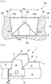
- Fig.3 is a schematic cross sectional view taken along line III-III in Fig. 1 .
- Fig.4 is a schematic perspective view of a portion of the molding element without an insert or a spacer according to the first embodiment of the present invention.
- Fig.5 is a schematic perspective view of a portion of the molding element with the insert and the spacer according to the first embodiment of the present invention.
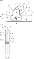
- Fig.6 is a schematic side view of the insert with the spacer before being received in a space according to the first embodiment of the present invention.
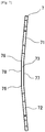
- Fig.7 is a schematic top view of the spacer according to the first embodiment of the present invention.
- the tread 101 is a tread for a tire having dimension 205/55R16 and comprises a contact face 102 intended to come into contact with the ground during rolling, a plurality of grooves 103 extending in a tire circumferential direction indicated as XX'.
- the groove 103 is delimited by two groove side faces 1031, 1032 facing each other and being connected by a groove bottom 1033.
- the groove 103 has a width W at a level of the contact face 102 and a depth D (as shown in Fig.3 ).
- a contact patch 106 has a contact patch length L in a tire circumferential direction when the tire with the tread 101 is mounted onto its standard rim and inflated at its nominal pressure and its nominal load is applied.
- the standard rim for this size is 6.5J
- the nominal pressure is 250kPa
- the nominal load is 615kg.
- a plurality of closing device 105 is provided in the groove 103.
- the closing device 105 comprises one first flexible fence 1051 and two second flexible fences 1052 for dividing an air column created between the ground and the groove 103 in the contact patch 106 during rolling.
- Closing devices 105 are provided at a regular interval of distance P in the tire circumferential direction in the groove 103.
- the distance P is preferably shorter than the contact patch length L as to at least one closing device 105 in each groove 103 is always located in the contact patch 106 during rolling.
- the first flexible fence 1051 has a thickness of t1 and extends from the groove bottom 1033 of the groove 103.
- Two second flexible fences 1052 have a thickness of t2 and extend from each of the opposite groove sidewalls 1031, 1032.
- Two second flexible fences 1052 in the same closing device 105 are offset each other in a circumferential direction in the groove 103.
- the first flexible fence 1051 is placed at a position circumferentially between two second flexible fences 1052, 1052 and distant from first flexible fence 1051 in circumferential direction (a direction along which the groove 103 extends) in the groove 103, as shown in Fig.2 .
- the thickness t1 of the first flexible fence 1051 is thinner than the thickness t2 of the second flexible fence 1052, as shown in Fig.2 .
- the first and the second flexible fences 1051, 1052 partly overlap in a circumferential direction (in sectional view of the groove 103), and the two second flexible fences 1052, 1052 also overlap partly in a circumferential direction (in sectional view of the groove 103).
- the first and the second flexible fences 1051, 1052 cover at least equal to 70% of the cross sectional area of the groove 103, as shown in Fig.3 .
- the first flexible fence 1051 has a pentagon shape extending from the groove bottom 1033 toward radially outward direction of the tread 101.
- the width of the first flexible fence 1051 is less than the width of the groove bottom 1033 at its bottom and the height of the first flexible fence 1051 is less than the depth D of the groove 103.
- a radially inward edge of the second flexible fence 1052 extends obliquely upwardly from the groove sidewall 1031, 1032 so as to form a triangular space thereunder with the groove bottom 1033.
- a radially outward portion of the second flexible fence 1052 extends substantially parallel to the contact face 102.
- a radially outer edge of the second flexible fence 1052 extends substantially parallel to the contact face 102.
- the axial length (width) of the second flexible fence 1052 is less than the width W of the groove 103.
- the tread 101 has the same structure as the conventional tread except for an arrangement regarding the closing device 105 and is intended to be applied to a conventional pneumatic radial, non-radial and other non-pneumatic tire. Thus, description of the internal construction of the tread 101 will be omitted.
- the groove 103 is provided with the plurality of closing device 105 each covering at least equal to 70% of the radial cross sectional area of the groove 103. Therefore, the length of the air column formed by the groove 103 in the contact patch 106 is shifted to a length whose groove resonance peak is outside of the frequency audible range for the human ear. Thus, groove resonance due to air column resonance of the groove 103 can be harmless.
- the flexible fences of the closing device 105 are provided so as to be distant each other with the offset in a direction along which the groove 103 extends. Therefore, it is possible to effectively improve groove resonance due to air column as a sound wave generated by groove resonance has difficulty to propagate between each the flexible fences of the closing device 105.
- the closing device 105 includes one first flexible fence 1051 and two second flexible fences 1052 and each of the second flexible fences 1052 extends from each of opposite groove sidewalls 1031, 1032. Therefore, it is possible to effectively cover as broader cross sectional area of the groove 103 as possible by the closing device 105, while maintaining good productivity of the tread 101 with the flexible fences as closing device 105, as the sectional area covered by each flexible fence can be reduced, resulting in higher flexibility of an arrangement of the first and the second flexible fences 1051, 1052.
- the first flexible fence 1051 and the second flexible fence 1052 of the closing device 105 overlap partly in a circumferential direction (in sectional view of the groove 103). Also, two second flexible fences 1052 of the closing device 105 overlap partly in a circumferential direction (in sectional view of the groove 103). Therefore, it is possible to further effectively attenuate groove resonance due to air column resonance of the groove 103, as the sound wave generated by groove resonance has more difficulty to propagate between each the flexible fences of the closing device 105.
- the thickness t1 of the first flexible fence 1051 is thinner than the thickness t2 of the second flexible fence 1052. It is possible to have easier bending of the first flexible fence 1051 even with reduced groove depth, which results further improvement on drainage capability.
- the offset between the flexible fences 1051, 1052 of the closing device 105 may be different for each locations, and the thickness t2 of the second flexible fence 1052 may have different thickness one another.
- a molding element 1 for a mold used for manufacturing the tread 101 will be described referring to Figs.4 , 5 , 6 and 7 .
- the molding element 1 has a base portion 2 having a molding surface 21 intended to mold the contact face 102 of the contacting element 104.
- the base portion 2 has two side faces 11, 12 facing to circumferentially opposed directions. These side faces 11, 12 define circumferential extremities of the molding element 1.
- one side face 11 or 12 of one molding element 1 is contacted to the other side face 12 or 11 of the adjacent molding elements to form a mold.
- the molding element 1 also has a groove forming rib portion 3.
- the groove forming rib portion 3 has a trapezoid cross section and radially integrally extends from the molding surface 21 of the base portion 2 in a radially inward direction of the molding element 1.
- the groove forming rib portion 3 includes two opposed rib side faces 31, 32 intended to mold two opposed groove side faces 1031, 1032, and a rib top face 33 intended to mold a bottom of the groove 1033.
- a radial position of the rib top face 33 can be the same among the these groove forming rib portions 3, or can be different among the these groove forming rib portions 3.
- the circumferential length of the groove forming rib portion 3 is shorter than that of the base portion 2 by depth Ls.
- a circumferential end surface 38 of the groove forming rib portion 3 is placed at a position backwardly from the side face 12 of the base portion 2 by depth Ls.
- a rectangular area in the side face 12 below (or radially outwardly of) the groove forming rib portion 3 is backwardly offset from the side face 12 of the base portion 2 by depth Ls so as to form a space 39, specifically a rectangular recessed space 39 having depth Ls.
- the molding element 1 also comprises an insert 5 including an upper portion 5a having a trapezoid cross section corresponding to that of the groove forming rib portion 3 and a lower portion 5b having a rectangular cross section corresponding to that of the rectangular recessed space 39, as shown in Fig. 5 .
- the insert 5 is fixedly secured to the base portion 2 and the groove forming rib portion 3 together with a spacer 7 such that the spacer 7 abuts against the circumferential end surface 38 of the groove forming rib portion 3 and the lower portion 5b is received in the rectangular recessed space 39, as shown in Fig.5 .
- Total thickness of the insert 5 and the spacer 7 after received in the space 39 is the same as the above offset depth Ls of the circumferential end surface 38 of the groove forming rib portion 3 and the depth Ls of the rectangular recessed space 39. Therefore, an outer surface 58 of the insert 5 is flush with the side face 12 of the base portion 2.
- the insert 5 and the spacer 7 are fixed to the groove forming rib portion 3 by a fixing means such that the spacer is placed between the insert 5 and the circumferential end surface 38 of the groove forming rib portion 3 and such that a screw extending through a hole 391 in a groove forming rib portion 3 and a hole 59 in the insert 5.
- the insert 5 and the spacer 7 may be fixed to the groove forming rib portion 3 by other manner such as welding, gluing, etc. In this case, the holes 59, 391 may not be provided.
- the insert 5 and the spacer 7 may be fixed to the groove forming rib portion 3 in a reverse order, that is to say the insert 5 is fixedly secured directly to the base portion 2 and the groove forming rib portion 3 such that the upper portion 5a of the insert 5 abuts against the circumferential end surface 38 of the groove forming rib portion 3.
- the insert 5 may be sandwiched by two spacers 7, or multiple numbers of spacer 7 may be provided at the same time. In such the case, each spacer 7 may have same or different thickness.
- the insert 5 and the spacer 7 can be placed in any position in the groove forming rib portion 3.
- the insert 5 together with the spacer 7 can be placed so as to be disclosed in WO2010/146180A1 , for example.
- the insert 5 can be integrally provided with the spacer 7.
- a surface 57 of the insert 5 contacts with a surface 78 of the spacer 7 between two bended portions 76, 76 before being received in the space 39, as shown in Fig.7 , thus creating a small space between the insert 5 and the spacer 7 outward of the bended portion 76 of the spacer 7.
- the spacer 7 changes its shape to almost or completely flat shape, thus the surface 57 of the insert 5 contacts almost completely with the surface 78 of the spacer 7.
- An insert top face 53 of the insert 5 which face has a slit (not shown) for molding the first flexible fence 1051 is provided so as to be flush with a spacer top face 73 when the insert 5 is received in the space 39 together with the spacer 7.
- An insert side face 52 of the insert 5 which face has a slit 521 for molding the second flexible fence 1052 is provided so as to be flush with a spacer side face 72 when the insert 5 is received in the space 39 together with the spacer 7.
- An insert side face 51 of the insert 5 which face has another slit (not shown) for forming the second flexible fence 1052 is provided so as to be flush with a spacer side face 71 (not shown) when the insert 5 is received in the space 39 together with the spacer 7.
- a contour of the spacer 7 is generally or completely the same as an outline shape of the inert 5.
- the space 7 is provided with a hole (not shown) aligned with the hole 59 of the insert 5 and the hole 391 of the space 39 for receiving a screw.
- a length Li between the outer surface 58 of the insert 5 and a surface 77 of the space 7 that are not in contact each other creates a length Li which is equal to or longer than the length (the depth) Ls of the space 39.
- a difference between the length Li of the insert 5 and the spacer 7 before being received into the space 39 and the length (the depth) Ls of the space 39 is preferably smaller than or equal to 1.0mm, more preferably greater than or equal to 0.0mm and smaller than or equal to 0.5mm, still more preferably smaller than or equal to 0.3mm and particularly smaller than or equal to 0.2mm.
- a gap between the insert 5 and the spacer 7 when being received in the space 39 is less than or equal to 0.05mm, preferably less than or equal to 0.04mm for avoid a rubber flashing after curing.
- any material able to resist force applied during vulcanization and possible to exert the spring characteristics for example metal, ceramic, resin (such as synthetic resin, for example), elastomeric material, plastic, composite material or mixture of these materials, is usable as a material for making the spring for the spacer 7.
- Both the insert 5 and the spacer 7 may be covered completely or partly with a non-stick material or coating for better and easier demolding.
- the non-stick material is, for example xylane.
- a difference in thickness between the insert 5 and the space 39 receiving the insert 5 in a molding element 1 can be filled up or compensated by the spring characteristics (deformation) of the spacer 7 leading better quality of the tread 101 with the flexible fence 1051, 1052 of the closing device 105 as the spacer 7 in the form of the leaf spring would be compressed when received in the space 39 and changes its form to fill a gap between the insert 5 and the molding element 1.
- the difference in thickness between the insert 5 and the space 39 receiving the insert 5 in the molding element 1 can be filled up or compensated thanks to the spring characteristics of the spacer 7, productivity of the molding element is maintained.
- the spacer 7 has at least two surfaces 77, 78 intended to be in contact with the insert 5 and/or a face 38 of the groove forming rib portion 3 facing to or defining the space 39, a gap between the spacer 7 and the insert 5 and/or between the spacer 7 and the face 38 of the groove forming rib portion 3 facing to the space 39 can easily be maintained for not having a rubber flashing not only on a contact face 102 but also in a groove 103 close to the closing device 105 leading further better quality of the tread 101 with the flexible fence 1051, 1052 of the closing device 105.
- This difference between the total thickness Li of the insert 5 and the spacer 7 before being received into the space 39 and the length (the depth) Ls of the space 39 is preferably greater than or equal to 0.0mm and smaller than or equal to 0.5mm, more preferably smaller than or equal to 0.3mm and still more preferably smaller than or equal to 0.2mm.
- the gap between the insert 5 and the spacer 7 when received into the space 39 is less than or equal to 0.05mm, it is possible to have further high quality of the tread 101 with the flexible fence 1051, 1052 of the closing device 105 as it is possible to avoid a rubber flashing from such the gap after curing.
- This gap between the insert 5 and the spacer 7 when received into the space 39 is preferably smaller than or equal to 0.04mm.
- the spacer 7 may be attached to the insert 5 inversely before being received into the space 39, that is to say two lateral ends of the spacer 7 contact with the insert 5 before being received into the space 39.
- FIG.8 is a schematic top view of a spacer according to the second embodiment of the present invention.
- the constitution of the second embodiment is similar to that of the first embodiment other than the arrangement shown in Fig.8 , thus description will be made referring to Fig.8 .
- a spacer 27 includes two parts, a bended part 27a and a flat part 27b, and the bended part 27a and the flat part 27b are joined at an interface 74.
- the bended part 27a bends at two bended portions 276, 276.
- the bended part 27a changes its shape to almost or completely flat so as to be integrated with or conform to the flat part 27b, thus a spacer top face 273 will be flush with an insert top face 53, two spacer side faces 271, 272 will be flush with two insert side faces 51, 52 respectively.
- Two surfaces 277, 278 of the spacer 27 would contact to the insert 5 or to the molding element 1.
- the spacer 27 includes two parts, it is possible to have high quality of the tread 101 with the flexible fence 1051, 1052 of the closing device 105 as it is possible to achieve improved contact of the spacer 7 with the insert 5 or with the molding element by using deformable portion (the bended part 27a) and non-deformable portion (the flat part 27b) separated each other.
- FIG.9 is a schematic top view of a spacer according to the third embodiment of the present invention.
- Fig. 10 is a schematic side view of the insert with the spacer and a supporting plate before being received in a space according to the third embodiment of the present invention.
- the constitution of this third embodiment is similar to that of the first embodiment other than the arrangement shown in Fig.9 and Fig. 10 , thus description will be made referring to Fig.9 and Fig. 10 .
- a spacer 37 includes two bended parts 37a, 37b joined at an interface 374. Each the bended parts 37a, 37b bend at two bended portions 376, 376, as shown in Fig.9 .
- the bended parts 37a, 37b change their shape to almost or completely flat shape so as to be aligned and stacked each other, thus a spacer top face 373 will be flush with an insert top face 53, and two spacer side faces 371, 372 will be flush with two insert side faces 51, 52, respectively.
- Two surfaces 377, 378 of the spacer 37 would contact to the insert 5 or to the molding element 1.
- the insert 5 is arranged so as to be integrated with the spacer 37 and a supporting plate 9.
- a surface 57 of the insert 5 contacts with a surface 378 of the spacer 37
- the supporting plate 9 contacts with a surface 377 of the spacer 37.
- the insert 5 includes an insert top face 53 having a slit for forming the first flexible fence 1051 (not shown) and being flush with a spacer top face 373 when the insert 5 is received in the space 39 together with the spacer 37 and the supporting plate 9.
- the insert 5 also includes an insert side face 52 having a slit 521 for forming the second flexible fence 1052 and being flush with a spacer side face 372 when the insert 5 is received in the space 39 together with the spacer 37 and the supporting plate 9.
- the insert 5 also includes an insert side face 51 having another slit for forming the second flexible fence 1052 (not shown) and being flush with a spacer side face 371 (not shown) when the insert 5 is received in the space 39 together with the spacer 37 and the supporting plate 9.
- the spacer 37 and the supporting plate 9 When received in the space 39, the spacer 37 and the supporting plate 9 have generally or completely the same contour as the inert 5.
- the insert 5 is received in the space 39 together with the spacer 37 and at least one supporting plate 9, it is possible to have high quality of the tread 101 with the flexible fence 1051, 1052 of the closing device 105 as it is possible to have good contact of the insert 5 together with the spacer 37 and the supporting plate 9 to the molding element 1 by using deformable portion (the spacer 37) and non-deformable portion (the supporting plate 9) separated each other.
- the total thickness Li of the insert and the spacer should also consider the supporting plate 9 in its length.
- Two supporting plates may be provided so as to sandwich both the insert 5 and the spacer 37.
- the supporting plate 9 also may be provided between the insert 5 and the spacer 37.
Description
- The present invention relates to a molding element, in particular to a molding element for a mold used for manufacturing a tread for a tire having a closing device in a groove.
- A groove resonance is generated by occurrence of resonance in an air column defined between a groove in a tread and a road surface in contact with the tire. The frequency of this groove resonance is dependent on a length of the air column formed between groove and the road surface in the contact patch.
- This groove resonance has a consequence in an interior noise and an exterior noise on a vehicle equipping such tires, a frequency of which interior and exterior noise is often at around 1 kHz where human ear is sensitive.
- In order to reduce such groove resonance, it is known to provide a plurality of closing device in the form of a thin flexible fence made of rubber-based material in each groove. It is effective that each flexible fence covers all or at least major part of the sectional area in the groove. Each flexible fence can extend from a groove bottom, or from at least one of groove sidewalls delimiting such groove. Because being relatively thin, each flexible fence has to bend for opening the groove section to flow water on the road surface, in particular on the wet road.
- Thanks to such flexible fences, the length of the air column is reduced so as to be shorter than the total length of groove in a contact patch, which leads to change the frequency of groove resonance. This change of resonance frequency makes the sound generated by the groove resonance less sensitive to human ear.
- For preserving function of drainage, in case of driving in rainy weather, it is necessary for such flexible fence to bend in a suitable way under the action of the pressure of water for opening the section of the groove. Several solutions have been proposed using this type of closing device to reduce groove resonance of the groove.
-
WO2013/178473 discloses, inFig.4 , a method for manufacturing a tread for a tire provided with at least one flexible wall (closing device) in a groove, the method comprising steps of molding the tread with a groove and at least one connecting element arranged inside the groove transversely so as to connect sidewalls of the groove, and cutting the connecting element at the junction with each the sidewall of the groove. However with such method productivity of such tread is low, as the method requires additional process of cutting the connecting element after molding. -
WO2013/120783 discloses, inFig.5 , a mold for molding a tread for a tire provided with at least one closing device, the mold comprising two cavities created in two added elements for the flexible fence separated by a first element, the assembly made up of the first element and the added elements forms an insert. -
- [PTL 1]
WO2013/178473 - [PTL 2]
WO2013/120783 - However, since the insert comprises several parts, a thickness of the insert and a thickness of a space receiving such the insert in a molding element may be different due to accumulation of a thickness variation of each part of the insert even all the parts forming the insert are within their thickness tolerance. If the thickness of the insert is thicker than the thickness of the space receiving such the insert, the insert may not be able to be received in the space, or a tread after curing may have a rubber flashing on its contact face because the insert may disturb a complete contact between the molding elements. If the thickness of the insert is thinner than the thickness of the space receiving such the insert, a tread after curing may have a rubber flashing in a groove close to the closing device. Such the problem becomes more remarkable when each the parts in the insert is treated with an anti-sticking coating for better demolding; need to consider a tolerance of a thickness of the anti-sticking coating either. Therefore, it is required to provide element to absorb such the difference in thickness between the insert and the space for receiving the insert in the molding element for better quality of the tread with the flexible fence of the closing device after curing without impacting productivity of such the molding element.
- A "tire" means all types of elastic tire whether or not subjected to an internal pressure.
- A "tread" of a tire means a quantity of rubber material bounded by lateral surfaces and by two main surfaces one of which is intended to come into contact with ground when the tire is rolling.
- A "mold" means a collection of separate molding elements which, when brought closer towards one another, delimit a toroidal molding space.
- A "molding element" of a mold means part of a mold. A molding element is, for example, a mold segment.
- A "molding surface" of a molding element means a surface of the mold that is intended to mold a surface of the tread.
- A "groove" is a space between two rubber faces/sidewalls which do not contact between themselves under usual rolling condition connected by another rubber face/bottom. A groove has a width and a depth.
- It is thus an object of the invention to provide a molding element for a mold used for manufacturing a tread of a tire, such molding element can improve quality of the tread provided with of the flexible fence of the closing device after curing while ensuring productivity of such the molding element.
- The present invention provide a molding element for a mold used for manufacturing a tread of a tire having a plurality of contacting element delimited by a plurality of grooves, the molding element having a molding surface for forming a contact face of the contacting elements intended to come into contact with ground during rolling and a groove forming rib portion for forming the groove between adjacent contacting elements comprising two opposed rib side faces for forming two opposed groove side faces and a rib top face connecting two rib side faces for forming a groove bottom, the groove forming rib portion comprising at least one space of a depth Ls opening to at least one of the rib side faces and/or to the rib top face and an insert being received in the space for forming a portion of the groove and a closing device in the groove, the insert is received in the space together with at least one spacer in a form of a leaf spring, a disc spring, a flat spring or a combination of these springs, the insert and the spacer before being received into the space having a total thickness Li, the spacer has at least two contact faces intended to be in contact with the insert and/or a face of the groove forming rib portion defining to the space, the spacer has no surface facing to a slit in the insert for forming a flexible fence of the closing device.
- This arrangement improves quality of a tread provided with a plurality of flexible fence of a closing device in a groove while ensuring good productivity of such the mold element.
- Since the insert is received in the space together with at least one spacer in a form of a leaf spring, a disc spring, a flat spring or a combination of these springs, a difference in thickness between the insert and a space receiving the insert in a molding element can be filled up or compensated by spring characteristics of the spacer leading better quality of the tread with the flexible fence of the closing device as the spacer in the form of the leaf spring, the disc spring, the flat spring or the combination of these springs would be compressed and deformed when received in the space and changes its form to fill a gap between the insert and the molding element. As the difference in thickness between the insert and the space receiving the insert in the molding element can be filled up or compensated thanks to the spring characteristics of the spacer, productivity of the molding element is maintained.
- Since the spacer has at least two contact faces intended to be in contact with the insert and/or a face of the groove forming rib portion facing to the space, a gap between the spacer and the insert and/or between the spacer and a face of the groove forming rib portion facing to the space can easily be maintained for not having a rubber flashing not only on a contact face but also in a groove close to the closing device leading further better quality of the tread with the flexible fence of the closing device.
- In another preferred embodiment, the total thickness Li of the insert and the spacer before being received into the space is larger than or equal to the depth Ls of the space, and a difference between the total thickness Li of the insert and the spacer before being received into the space and the depth Ls of the space is smaller than or equal to 1.0mm.
- If this gap is more than 1.0mm, deformation of the spacer due to compression upon being received into the space with the insert may affect formation of the groove after curing, or may affect a slit in the insert for forming the flexible fence of the closing device resulting low quality of the tread after curing.
- This gap between the total thickness Li of the insert and the spacer before being received into the space and the depth Ls of the space is preferably greater than or equal to 0.0mm and smaller than or equal to 0.5mm, more preferably smaller than or equal to 0.3mm and still more preferably smaller than or equal to 0.2mm.
- In another preferred embodiment, a gap between the insert and the spacer when received into the space is smaller than or equal to 0.05mm.
- According to this arrangement, it is possible to have further high quality of the tread with the flexible fence of the closing device as it is possible to avoid a rubber flashing from such the gap after curing.
- In another preferred embodiment, the insert is received in the space together with the spacer and at least one supporting plate.
- According to this arrangement, it is possible to have further high quality of the tread with the flexible fence of the closing device as it is possible to achieve improved contact between the insert and the spacer and the molding element by using deformable portion (the spacer) and non-deformable portion (the supporting plate) separated each other.
- In case the insert is provided together with the spacer and the supporting plate, the total thickness Li of the insert and the spacer should also consider the supporting plate in its length.
- Other characteristics and advantages of the invention arise from the description made hereafter in reference to the annexed drawings which show, as nonrestrictive examples, the embodiment of the invention.
- In these drawings:
- [
Fig. 1 ]
Fig.1 is a schematic plan view of a tread for a tire molded with a mold comprising a molding element according to a first embodiment of the present invention; - [
Fig. 2 ]
Fig.2 is an enlarged schematic plan view showing a portion indicated as II inFig. 1 ; - [
Fig. 3 ]
Fig.3 is a schematic cross sectional view taken along line III-III inFig.1 ; - [
Fig. 4 ]
Fig.4 is a schematic perspective view of a portion of the molding element without an insert or a spacer according to the first embodiment of the present invention; - [
Fig. 5 ]
Fig.5 is a schematic perspective view of a portion of the molding element with the insert and the spacer according to the first embodiment of the present invention; - [
Fig. 6 ]
Fig.6 is a schematic side view of the insert with the spacer before being received in a space according to the first embodiment of the present invention; - [
Fig. 7 ]
Fig.7 is a schematic top view of the spacer according to the first embodiment of the present invention; - [
Fig. 8 ]
Fig.8 is a schematic top view of a spacer according to a second embodiment of the present invention; - [
Fig. 9 ]
Fig.9 is a schematic top view of a spacer according to a third embodiment of the present invention; - [
Fig. 10 ]
Fig. 10 is a schematic side view of the insert with the spacer and a supporting plate before receiving in a space according to the third embodiment of the present invention; - Preferred embodiments of the present invention will be described below referring to the drawings.
- A
molding element 1 for a mold used for manufacturing atread 101 of a tire, a mold comprising themolding element 1, and atread 101 molded and vulcanized using the mold according to a first embodiment of the present invention will be described referring toFigs. 1 to 7 . -
Fig.1 is a schematic plan view of a tread for a tire molded with a mold comprising a molding element according to the first embodiment of the present invention.Fig.2 is an enlarged schematic plan view showing a portion indicated as II inFig.1 .Fig.3 is a schematic cross sectional view taken along line III-III inFig. 1 .Fig.4 is a schematic perspective view of a portion of the molding element without an insert or a spacer according to the first embodiment of the present invention.Fig.5 is a schematic perspective view of a portion of the molding element with the insert and the spacer according to the first embodiment of the present invention.Fig.6 is a schematic side view of the insert with the spacer before being received in a space according to the first embodiment of the present invention.Fig.7 is a schematic top view of the spacer according to the first embodiment of the present invention. - The
tread 101 is a tread for a tire having dimension 205/55R16 and comprises acontact face 102 intended to come into contact with the ground during rolling, a plurality ofgrooves 103 extending in a tire circumferential direction indicated as XX'. Thegroove 103 is delimited by two groove side faces 1031, 1032 facing each other and being connected by agroove bottom 1033. Thegroove 103 has a width W at a level of thecontact face 102 and a depth D (as shown inFig.3 ). - As shown in
Fig.1 , acontact patch 106 has a contact patch length L in a tire circumferential direction when the tire with thetread 101 is mounted onto its standard rim and inflated at its nominal pressure and its nominal load is applied. According to 'ETRTO Standard Manual 2016' the standard rim for this size is 6.5J, the nominal pressure is 250kPa and the nominal load is 615kg. - As shown in
Fig.1 , in thegroove 103, a plurality ofclosing device 105 is provided. Theclosing device 105 comprises one firstflexible fence 1051 and two secondflexible fences 1052 for dividing an air column created between the ground and thegroove 103 in thecontact patch 106 during rolling. Closingdevices 105 are provided at a regular interval of distance P in the tire circumferential direction in thegroove 103. The distance P is preferably shorter than the contact patch length L as to at least oneclosing device 105 in eachgroove 103 is always located in thecontact patch 106 during rolling. - The first
flexible fence 1051 has a thickness of t1 and extends from thegroove bottom 1033 of thegroove 103. Two secondflexible fences 1052 have a thickness of t2 and extend from each of the opposite groove sidewalls 1031, 1032. Two secondflexible fences 1052 in thesame closing device 105 are offset each other in a circumferential direction in thegroove 103. The firstflexible fence 1051 is placed at a position circumferentially between two secondflexible fences flexible fence 1051 in circumferential direction (a direction along which thegroove 103 extends) in thegroove 103, as shown inFig.2 . - The thickness t1 of the first
flexible fence 1051 is thinner than the thickness t2 of the secondflexible fence 1052, as shown inFig.2 . The first and the secondflexible fences flexible fences flexible fences groove 103, as shown inFig.3 . - As shown in
Fig.3 , the firstflexible fence 1051 has a pentagon shape extending from thegroove bottom 1033 toward radially outward direction of thetread 101. The width of the firstflexible fence 1051 is less than the width of thegroove bottom 1033 at its bottom and the height of the firstflexible fence 1051 is less than the depth D of thegroove 103. - Further, a radially inward edge of the second
flexible fence 1052 extends obliquely upwardly from thegroove sidewall groove bottom 1033. A radially outward portion of the secondflexible fence 1052 extends substantially parallel to thecontact face 102. A radially outer edge of the secondflexible fence 1052 extends substantially parallel to thecontact face 102. The axial length (width) of the secondflexible fence 1052 is less than the width W of thegroove 103. - The
tread 101 has the same structure as the conventional tread except for an arrangement regarding theclosing device 105 and is intended to be applied to a conventional pneumatic radial, non-radial and other non-pneumatic tire. Thus, description of the internal construction of thetread 101 will be omitted. - The
groove 103 is provided with the plurality ofclosing device 105 each covering at least equal to 70% of the radial cross sectional area of thegroove 103. Therefore, the length of the air column formed by thegroove 103 in thecontact patch 106 is shifted to a length whose groove resonance peak is outside of the frequency audible range for the human ear. Thus, groove resonance due to air column resonance of thegroove 103 can be harmless. - The flexible fences of the
closing device 105 are provided so as to be distant each other with the offset in a direction along which thegroove 103 extends. Therefore, it is possible to effectively improve groove resonance due to air column as a sound wave generated by groove resonance has difficulty to propagate between each the flexible fences of theclosing device 105. - The
closing device 105 includes one firstflexible fence 1051 and two secondflexible fences 1052 and each of the secondflexible fences 1052 extends from each of opposite groove sidewalls 1031, 1032. Therefore, it is possible to effectively cover as broader cross sectional area of thegroove 103 as possible by theclosing device 105, while maintaining good productivity of thetread 101 with the flexible fences as closingdevice 105, as the sectional area covered by each flexible fence can be reduced, resulting in higher flexibility of an arrangement of the first and the secondflexible fences - The first
flexible fence 1051 and the secondflexible fence 1052 of theclosing device 105 overlap partly in a circumferential direction (in sectional view of the groove 103). Also, two secondflexible fences 1052 of theclosing device 105 overlap partly in a circumferential direction (in sectional view of the groove 103). Therefore, it is possible to further effectively attenuate groove resonance due to air column resonance of thegroove 103, as the sound wave generated by groove resonance has more difficulty to propagate between each the flexible fences of theclosing device 105. - The thickness t1 of the first
flexible fence 1051 is thinner than the thickness t2 of the secondflexible fence 1052. It is possible to have easier bending of the firstflexible fence 1051 even with reduced groove depth, which results further improvement on drainage capability. - The offset between the
flexible fences closing device 105 may be different for each locations, and the thickness t2 of the secondflexible fence 1052 may have different thickness one another. - Next, a
molding element 1 for a mold used for manufacturing thetread 101 will be described referring toFigs.4 ,5 ,6 and7 . - As shown in
Fig.4 , themolding element 1 has abase portion 2 having amolding surface 21 intended to mold thecontact face 102 of the contactingelement 104. Thebase portion 2 has two side faces 11, 12 facing to circumferentially opposed directions. These side faces 11, 12 define circumferential extremities of themolding element 1. - In use, one
side face molding element 1 is contacted to the other side face 12 or 11 of the adjacent molding elements to form a mold. - As shown in
Fig.4 , themolding element 1 also has a groove formingrib portion 3. The groove formingrib portion 3 has a trapezoid cross section and radially integrally extends from themolding surface 21 of thebase portion 2 in a radially inward direction of themolding element 1. - The groove forming
rib portion 3 includes two opposed rib side faces 31, 32 intended to mold two opposed groove side faces 1031, 1032, and a rib top face 33 intended to mold a bottom of thegroove 1033. In case plurality of groove formingrib portions 3 is provided in onemolding element 1, a radial position of the rib top face 33 can be the same among the these groove formingrib portions 3, or can be different among the these groove formingrib portions 3. - The circumferential length of the groove forming
rib portion 3 is shorter than that of thebase portion 2 by depth Ls. As shown inFig.4 , acircumferential end surface 38 of the groove formingrib portion 3 is placed at a position backwardly from theside face 12 of thebase portion 2 by depth Ls. Further, a rectangular area in theside face 12 below (or radially outwardly of) the groove formingrib portion 3 is backwardly offset from theside face 12 of thebase portion 2 by depth Ls so as to form aspace 39, specifically a rectangular recessedspace 39 having depth Ls. - The
molding element 1 also comprises aninsert 5 including anupper portion 5a having a trapezoid cross section corresponding to that of the groove formingrib portion 3 and alower portion 5b having a rectangular cross section corresponding to that of the rectangular recessedspace 39, as shown inFig. 5 . - The
insert 5 is fixedly secured to thebase portion 2 and the groove formingrib portion 3 together with aspacer 7 such that thespacer 7 abuts against thecircumferential end surface 38 of the groove formingrib portion 3 and thelower portion 5b is received in the rectangular recessedspace 39, as shown inFig.5 . - Total thickness of the
insert 5 and thespacer 7 after received in thespace 39 is the same as the above offset depth Ls of thecircumferential end surface 38 of the groove formingrib portion 3 and the depth Ls of the rectangular recessedspace 39. Therefore, anouter surface 58 of theinsert 5 is flush with theside face 12 of thebase portion 2. - The
insert 5 and thespacer 7 are fixed to the groove formingrib portion 3 by a fixing means such that the spacer is placed between theinsert 5 and thecircumferential end surface 38 of the groove formingrib portion 3 and such that a screw extending through ahole 391 in a groove formingrib portion 3 and ahole 59 in theinsert 5. - The
insert 5 and thespacer 7 may be fixed to the groove formingrib portion 3 by other manner such as welding, gluing, etc. In this case, theholes - The
insert 5 and thespacer 7 may be fixed to the groove formingrib portion 3 in a reverse order, that is to say theinsert 5 is fixedly secured directly to thebase portion 2 and the groove formingrib portion 3 such that theupper portion 5a of theinsert 5 abuts against thecircumferential end surface 38 of the groove formingrib portion 3. - The
insert 5 may be sandwiched by twospacers 7, or multiple numbers ofspacer 7 may be provided at the same time. In such the case, eachspacer 7 may have same or different thickness. - The
insert 5 and thespacer 7 can be placed in any position in the groove formingrib portion 3. In case a space for receiving theinsert 5 and thespacer 7 is provided at a position which is not facing to theside face molding element 1, theinsert 5 together with thespacer 7 can be placed so as to be disclosed inWO2010/146180A1 , for example. - As shown in
Fig.6 , theinsert 5 can be integrally provided with thespacer 7. Asurface 57 of theinsert 5 contacts with asurface 78 of thespacer 7 between twobended portions space 39, as shown inFig.7 , thus creating a small space between theinsert 5 and thespacer 7 outward of thebended portion 76 of thespacer 7. When theinsert 5 is received in thespace 39 together with thespacer 7, thespacer 7 changes its shape to almost or completely flat shape, thus thesurface 57 of theinsert 5 contacts almost completely with thesurface 78 of thespacer 7. - An insert
top face 53 of theinsert 5 which face has a slit (not shown) for molding the firstflexible fence 1051 is provided so as to be flush with a spacertop face 73 when theinsert 5 is received in thespace 39 together with thespacer 7. An insert side face 52 of theinsert 5 which face has aslit 521 for molding the secondflexible fence 1052 is provided so as to be flush with a spacer side face 72 when theinsert 5 is received in thespace 39 together with thespacer 7. An insert side face 51 of theinsert 5 which face has another slit (not shown) for forming the secondflexible fence 1052 is provided so as to be flush with a spacer side face 71 (not shown) when theinsert 5 is received in thespace 39 together with thespacer 7. - When received in the
space 39, a contour of thespacer 7 is generally or completely the same as an outline shape of the inert 5. Thespace 7 is provided with a hole (not shown) aligned with thehole 59 of theinsert 5 and thehole 391 of thespace 39 for receiving a screw. - When the
insert 5 is assembled with thespacer 7 before being received in thespace 39, a length Li between theouter surface 58 of theinsert 5 and asurface 77 of thespace 7 that are not in contact each other creates a length Li which is equal to or longer than the length (the depth) Ls of thespace 39. A difference between the length Li of theinsert 5 and thespacer 7 before being received into thespace 39 and the length (the depth) Ls of thespace 39 is preferably smaller than or equal to 1.0mm, more preferably greater than or equal to 0.0mm and smaller than or equal to 0.5mm, still more preferably smaller than or equal to 0.3mm and particularly smaller than or equal to 0.2mm. - A gap between the
insert 5 and thespacer 7 when being received in thespace 39 is less than or equal to 0.05mm, preferably less than or equal to 0.04mm for avoid a rubber flashing after curing. - Any material able to resist force applied during vulcanization and possible to exert the spring characteristics, for example metal, ceramic, resin (such as synthetic resin, for example), elastomeric material, plastic, composite material or mixture of these materials, is usable as a material for making the spring for the
spacer 7. - Both the
insert 5 and thespacer 7 may be covered completely or partly with a non-stick material or coating for better and easier demolding. The non-stick material is, for example xylane. - Since the
insert 5 is received in thespace 39 together with at least onespacer 7 in a form of a leaf spring, a disc spring, a flat spring or a combination of these springs, a difference in thickness between theinsert 5 and thespace 39 receiving theinsert 5 in amolding element 1 can be filled up or compensated by the spring characteristics (deformation) of thespacer 7 leading better quality of thetread 101 with theflexible fence closing device 105 as thespacer 7 in the form of the leaf spring would be compressed when received in thespace 39 and changes its form to fill a gap between theinsert 5 and themolding element 1. As the difference in thickness between theinsert 5 and thespace 39 receiving theinsert 5 in themolding element 1 can be filled up or compensated thanks to the spring characteristics of thespacer 7, productivity of the molding element is maintained. - Since the
spacer 7 has at least twosurfaces insert 5 and/or aface 38 of the groove formingrib portion 3 facing to or defining thespace 39, a gap between thespacer 7 and theinsert 5 and/or between thespacer 7 and theface 38 of the groove formingrib portion 3 facing to thespace 39 can easily be maintained for not having a rubber flashing not only on acontact face 102 but also in agroove 103 close to theclosing device 105 leading further better quality of thetread 101 with theflexible fence closing device 105. - Since the difference between the total thickness Li of the
insert 5 and thespacer 7 before being received into thespace 39 and the length (the depth) Ls of thespace 39 is less than or equal to 1.0mm, a deformation of thespacer 7 due to compression subjected upon being received into thespace 39 may not affect a form of thegroove 103 after curing, and may not affect the slit in theinsert 5 for folding theflexible fence closing device 105 resulting maintained high quality of thetread 101 after curing. - This difference between the total thickness Li of the
insert 5 and thespacer 7 before being received into thespace 39 and the length (the depth) Ls of thespace 39 is preferably greater than or equal to 0.0mm and smaller than or equal to 0.5mm, more preferably smaller than or equal to 0.3mm and still more preferably smaller than or equal to 0.2mm. - Since the gap between the
insert 5 and thespacer 7 when received into thespace 39 is less than or equal to 0.05mm, it is possible to have further high quality of thetread 101 with theflexible fence closing device 105 as it is possible to avoid a rubber flashing from such the gap after curing. This gap between theinsert 5 and thespacer 7 when received into thespace 39 is preferably smaller than or equal to 0.04mm. - The
spacer 7 may be attached to theinsert 5 inversely before being received into thespace 39, that is to say two lateral ends of thespacer 7 contact with theinsert 5 before being received into thespace 39. - A molding element according to a second embodiment of the present invention will be described referring to
Fig.8. Fig.8 is a schematic top view of a spacer according to the second embodiment of the present invention. The constitution of the second embodiment is similar to that of the first embodiment other than the arrangement shown inFig.8 , thus description will be made referring toFig.8 . - In the second embodiment, a
spacer 27 includes two parts, abended part 27a and aflat part 27b, and thebended part 27a and theflat part 27b are joined at aninterface 74. Thebended part 27a bends at twobended portions space 39 together with theinsert 5, thebended part 27a changes its shape to almost or completely flat so as to be integrated with or conform to theflat part 27b, thus a spacertop face 273 will be flush with aninsert top face 53, two spacer side faces 271, 272 will be flush with two insert side faces 51, 52 respectively. Twosurfaces spacer 27 would contact to theinsert 5 or to themolding element 1. - Since the
spacer 27 includes two parts, it is possible to have high quality of thetread 101 with theflexible fence closing device 105 as it is possible to achieve improved contact of thespacer 7 with theinsert 5 or with the molding element by using deformable portion (thebended part 27a) and non-deformable portion (theflat part 27b) separated each other. - A molding element according to a third embodiment of the present invention will be described referring to
Fig.9 andFig.10 .Fig.9 is a schematic top view of a spacer according to the third embodiment of the present invention.Fig. 10 is a schematic side view of the insert with the spacer and a supporting plate before being received in a space according to the third embodiment of the present invention. The constitution of this third embodiment is similar to that of the first embodiment other than the arrangement shown inFig.9 andFig. 10 , thus description will be made referring toFig.9 andFig. 10 . - In the third embodiment, a
spacer 37 includes twobended parts interface 374. Each thebended parts bended portions Fig.9 . In use, when being received into thespace 39 together with theinsert 5, thebended parts top face 373 will be flush with aninsert top face 53, and two spacer side faces 371, 372 will be flush with two insert side faces 51, 52, respectively. Twosurfaces spacer 37 would contact to theinsert 5 or to themolding element 1. - As shown in
Fig. 10 , theinsert 5 is arranged so as to be integrated with thespacer 37 and a supportingplate 9. Asurface 57 of theinsert 5 contacts with asurface 378 of thespacer 37, and the supportingplate 9 contacts with asurface 377 of thespacer 37. When theinsert 5 is received in thespace 39 together with thespacer 37 and the supportingplate 9, thespacer 37 changes its shape to almost or completely flat shape, thus thesurface 57 of theinsert 5 contacts almost completely with thesurface 378 of thespacer 37, the supportingplate 9 contacts almost completely with thesurface 377 of thespacer 37. - The
insert 5 includes an insert top face 53 having a slit for forming the first flexible fence 1051 (not shown) and being flush with a spacertop face 373 when theinsert 5 is received in thespace 39 together with thespacer 37 and the supportingplate 9. Theinsert 5 also includes an insert side face 52 having aslit 521 for forming the secondflexible fence 1052 and being flush with aspacer side face 372 when theinsert 5 is received in thespace 39 together with thespacer 37 and the supportingplate 9. Theinsert 5 also includes an insert side face 51 having another slit for forming the second flexible fence 1052 (not shown) and being flush with a spacer side face 371 (not shown) when theinsert 5 is received in thespace 39 together with thespacer 37 and the supportingplate 9. - When received in the
space 39, thespacer 37 and the supportingplate 9 have generally or completely the same contour as the inert 5. - Since the
insert 5 is received in thespace 39 together with thespacer 37 and at least one supportingplate 9, it is possible to have high quality of thetread 101 with theflexible fence closing device 105 as it is possible to have good contact of theinsert 5 together with thespacer 37 and the supportingplate 9 to themolding element 1 by using deformable portion (the spacer 37) and non-deformable portion (the supporting plate 9) separated each other. In such the case that theinsert 5 is provided together with thespacer 37 and the supportingplate 9, the total thickness Li of the insert and the spacer should also consider the supportingplate 9 in its length. - Two supporting plates may be provided so as to sandwich both the
insert 5 and thespacer 37. The supportingplate 9 also may be provided between theinsert 5 and thespacer 37. -
- 1
- molding element
- 11, 12
- side face
- 2
- base portion
- 21
- molding surface
- 3
- groove forming rib portion
- 31, 32
- rib side face
- 33
- rib top face
- 38
- end surface
- 39
- space
- 391
- hole
- 5
- insert
- 51, 52
- insert side face
- 521
- slit
- 53
- insert top face
- 57, 58
- surface
- 59
- hole
- 7, 27, 37
- spacer
- 71, 72, 271, 272, 371, 372
- spacer side face
- 73
- spacer top face
- 74,374
- interface
- 76, 276, 376
- bended portion
- 77, 78, 277, 278, 377, 378
- surface
- 9
- supporting plate
- 101
- tread
- 102
- contact face
- 103
- groove
- 1031, 1032
- groove side face
- 1033
- groove bottom
- 104
- contacting element
- 105
- closing device
- 1051, 1052
- flexible fence
- 106
- contact patch
Claims (5)
- A molding element (1) for a mold used for manufacturing a tread (101) of a tire having a plurality of contacting element (104) delimited by a plurality of grooves (103), the molding element (1) having a molding surface (21) for forming a contact face (102) of the contacting elements (104) intended to come into contact with ground during rolling and a groove forming rib portion (3) for forming the groove (103) between adjacent contacting elements (104) comprising two opposed rib side faces (31, 32) for forming two opposed groove side faces (1031, 1032) and a rib top face (33) connecting two rib side faces (31, 32) for forming a groove bottom (1033), the groove forming rib portion (3) comprising at least one space (39) of a depth Ls opening to at least one of the rib side faces (31, 32) and/or to the rib top face (33) and an insert (5) being received in the space (39) for forming a portion of the groove (103) and a closing device (105) in the groove (103),
the molding element being characterized in that the insert comprises at least two slits (521), at least one slit (521) opening to one of insert side faces (51, 52) for forming at least one second flexible fence (1052) and another slit (521) opening to an insert top face (53) for forming a first flexible fence (1051),
wherein the insert (5) is received in the space (39) together with at least one spacer (7) in a form of a leaf spring, a disc spring, a flat spring or a combination of these springs, the insert (5) and the spacer (7) before being received into the space (39) having a total thickness Li, wherein the spacer (7) has at least two surfaces (77, 78) intended to be in contact with the insert (5) and/or a face of the groove forming rib portion (3) defining to the space (39), and wherein the spacer (7) has no communication with the slits (521) in the insert (5) for forming the first flexible fence (1051) and the second flexible fence (1052) of the closing device (105). - The molding element (1) according to claim 1, wherein the total thickness Li of the insert and the spacer before being received into the space is larger than or equal to the depth Ls of the space, a difference between total thickness Li of the insert (5) and the spacer (7) before receiving into the space (39) and a depth Ls of the space (39) is smaller than or equal to 1.0mm.
- The molding element (1) according to claim 1 or claim 2, wherein a gap between the insert (5) and the spacer (7) when received into the space (39) is smaller than or equal to 0.05mm.
- The molding element (1) according to any one of the claims 1 to 3, wherein the insert (5) is received in the space (39) together with the spacer (7) and at least one supporting plate (9).
- A mold for vulcanizing and molding a tread for a tire, wherein the mold comprises at least one molding element (1) according to any one of the claims 1 to 4.
Applications Claiming Priority (2)
| Application Number | Priority Date | Filing Date | Title |
|---|---|---|---|
| JP2016079876 | 2016-09-29 | ||
| PCT/JP2017/035543 WO2018062507A2 (en) | 2016-09-29 | 2017-09-29 | Molding element for manufacturing a noise reducing tread |
Publications (2)
| Publication Number | Publication Date |
|---|---|
| EP3519174A2 EP3519174A2 (en) | 2019-08-07 |
| EP3519174B1 true EP3519174B1 (en) | 2020-12-16 |
Family
ID=57241138
Family Applications (1)
| Application Number | Title | Priority Date | Filing Date |
|---|---|---|---|
| EP17781208.8A Active EP3519174B1 (en) | 2016-09-29 | 2017-09-29 | Molding element for manufacturing a noise reducing tread |
Country Status (3)
| Country | Link |
|---|---|
| EP (1) | EP3519174B1 (en) |
| CN (1) | CN109789655B (en) |
| WO (1) | WO2018062507A2 (en) |
Family Cites Families (15)
| Publication number | Priority date | Publication date | Assignee | Title |
|---|---|---|---|---|
| US5223065A (en) * | 1988-01-26 | 1993-06-29 | The Yokohama Rubber Co., Ltd. | Pneumatic tire |
| AT400238B (en) * | 1992-09-24 | 1995-11-27 | Semperit Ag | TIRES |
| JP3815758B2 (en) * | 1997-10-06 | 2006-08-30 | 株式会社ブリヂストン | Heavy duty pneumatic tire |
| JP2000102925A (en) * | 1998-09-28 | 2000-04-11 | Ngk Fine Mold Kk | Sipe forming skeleton and production of tire mold |
| US6196818B1 (en) * | 1999-03-15 | 2001-03-06 | Bridgestone/Firestone Research, Inc. | Mold section and die ribs for tire curing mold |
| JP2002234313A (en) * | 2001-02-08 | 2002-08-20 | Bridgestone Corp | Pneumatic tire |
| US20020134202A1 (en) * | 2001-03-23 | 2002-09-26 | Andre Domange | Composite blade |
| FR2908068B1 (en) * | 2006-11-02 | 2009-01-16 | Michelin Soc Tech | METHOD FOR MOLDING A PNEUMATIC HAVING IMPROVED NOISE PERFORMANCE |
| BRPI0823145B1 (en) * | 2008-10-31 | 2018-12-04 | Pirelli | tire molding and vulcanization process and apparatus |
| FR2946915B1 (en) * | 2009-06-19 | 2011-06-17 | Michelin Soc Tech | REMOVABLE DEVICE FOR MOLDING A FLEXIBLE WALL IN A PNEUMATIC SCULPTURE SILL |
| FR2983115B1 (en) * | 2011-11-25 | 2014-06-20 | Michelin Soc Tech | MOLD COMPRISING A CAVITY FOR MOLDING A CLOSURE DEVICE IN A GROOVE |
| FR2986736B1 (en) * | 2012-02-13 | 2014-10-03 | Michelin & Cie | MOLD FOR THE VULCANIZATION OF A TIRE TREAD OF A TIRE COMPRISING AT LEAST ONE ELEMENT REPORTED IN A CORD |
| FR2991234B1 (en) | 2012-05-31 | 2015-04-03 | Michelin & Cie | METHOD FOR MANUFACTURING A FLEXIBLE WALL IN A PNEUMATIC BEARING TRAP |
| FR3029843A1 (en) * | 2014-12-12 | 2016-06-17 | Michelin & Cie | TIRE NOISE ATTENUATING DEVICE FOR TIRE |
| CN104708741B (en) * | 2015-03-25 | 2017-10-03 | 山东豪迈机械科技股份有限公司 | Tire-mold |
-
2017
- 2017-09-29 EP EP17781208.8A patent/EP3519174B1/en active Active
- 2017-09-29 WO PCT/JP2017/035543 patent/WO2018062507A2/en unknown
- 2017-09-29 CN CN201780060083.5A patent/CN109789655B/en active Active
Non-Patent Citations (1)
| Title |
|---|
| None * |
Also Published As
| Publication number | Publication date |
|---|---|
| WO2018062507A3 (en) | 2018-05-17 |
| WO2018062507A2 (en) | 2018-04-05 |
| EP3519174A2 (en) | 2019-08-07 |
| CN109789655A (en) | 2019-05-21 |
| CN109789655B (en) | 2021-07-23 |
Similar Documents
| Publication | Publication Date | Title |
|---|---|---|
| CN108430803B (en) | Noise reducing tread | |
| US11511504B2 (en) | Molding element for manufacturing a noise reducing tread | |
| CN109715415A (en) | Pneumatic vehicle tire | |
| EP3519173B1 (en) | Molding element for manufacturing a noise reducing tread | |
| EP3519174B1 (en) | Molding element for manufacturing a noise reducing tread | |
| EP3475045B1 (en) | Molding element for manufacturing a noise reducing tread | |
| US11247366B2 (en) | Molding element for manufacturing a noise reducing tread | |
| US11628640B2 (en) | Molding element for manufacturing a noise reducing tread | |
| EP3475044B1 (en) | Molding element for manufacturing a noise reducing tread | |
| RU2530200C2 (en) | Tire tread with cavities and slots | |
| EP3356102B1 (en) | Molding element for manufacturing a noise reducing tread | |
| WO2015090672A1 (en) | Moulding element comprising cutting means for moulding and vulcanizing a tyre tread |
Legal Events
| Date | Code | Title | Description |
|---|---|---|---|
| STAA | Information on the status of an ep patent application or granted ep patent |
Free format text: STATUS: UNKNOWN |
|
| STAA | Information on the status of an ep patent application or granted ep patent |
Free format text: STATUS: THE INTERNATIONAL PUBLICATION HAS BEEN MADE |
|
| PUAI | Public reference made under article 153(3) epc to a published international application that has entered the european phase |
Free format text: ORIGINAL CODE: 0009012 |
|
| STAA | Information on the status of an ep patent application or granted ep patent |
Free format text: STATUS: REQUEST FOR EXAMINATION WAS MADE |
|
| 17P | Request for examination filed |
Effective date: 20190328 |
|
| AK | Designated contracting states |
Kind code of ref document: A2 Designated state(s): AL AT BE BG CH CY CZ DE DK EE ES FI FR GB GR HR HU IE IS IT LI LT LU LV MC MK MT NL NO PL PT RO RS SE SI SK SM TR |
|
| AX | Request for extension of the european patent |
Extension state: BA ME |
|
| DAV | Request for validation of the european patent (deleted) | ||
| DAX | Request for extension of the european patent (deleted) | ||
| GRAP | Despatch of communication of intention to grant a patent |
Free format text: ORIGINAL CODE: EPIDOSNIGR1 |
|
| STAA | Information on the status of an ep patent application or granted ep patent |
Free format text: STATUS: GRANT OF PATENT IS INTENDED |
|
| INTG | Intention to grant announced |
Effective date: 20200525 |
|
| RIN1 | Information on inventor provided before grant (corrected) |
Inventor name: ROTY , GAEL Inventor name: PENGSALOONG, KHOTCHAKORN |
|
| GRAJ | Information related to disapproval of communication of intention to grant by the applicant or resumption of examination proceedings by the epo deleted |
Free format text: ORIGINAL CODE: EPIDOSDIGR1 |
|
| STAA | Information on the status of an ep patent application or granted ep patent |
Free format text: STATUS: REQUEST FOR EXAMINATION WAS MADE |
|
| INTC | Intention to grant announced (deleted) | ||
| GRAR | Information related to intention to grant a patent recorded |
Free format text: ORIGINAL CODE: EPIDOSNIGR71 |
|
| GRAS | Grant fee paid |
Free format text: ORIGINAL CODE: EPIDOSNIGR3 |
|
| STAA | Information on the status of an ep patent application or granted ep patent |
Free format text: STATUS: GRANT OF PATENT IS INTENDED |
|
| GRAA | (expected) grant |
Free format text: ORIGINAL CODE: 0009210 |
|
| STAA | Information on the status of an ep patent application or granted ep patent |
Free format text: STATUS: THE PATENT HAS BEEN GRANTED |
|
| AK | Designated contracting states |
Kind code of ref document: B1 Designated state(s): AL AT BE BG CH CY CZ DE DK EE ES FI FR GB GR HR HU IE IS IT LI LT LU LV MC MK MT NL NO PL PT RO RS SE SI SK SM TR |
|
| INTG | Intention to grant announced |
Effective date: 20201110 |
|
| REG | Reference to a national code |
Ref country code: GB Ref legal event code: FG4D |
|
| REG | Reference to a national code |
Ref country code: DE Ref legal event code: R096 Ref document number: 602017029711 Country of ref document: DE |
|
| REG | Reference to a national code |
Ref country code: IE Ref legal event code: FG4D |
|
| REG | Reference to a national code |
Ref country code: AT Ref legal event code: REF Ref document number: 1345207 Country of ref document: AT Kind code of ref document: T Effective date: 20210115 |
|
| PG25 | Lapsed in a contracting state [announced via postgrant information from national office to epo] |
Ref country code: RS Free format text: LAPSE BECAUSE OF FAILURE TO SUBMIT A TRANSLATION OF THE DESCRIPTION OR TO PAY THE FEE WITHIN THE PRESCRIBED TIME-LIMIT Effective date: 20201216 Ref country code: FI Free format text: LAPSE BECAUSE OF FAILURE TO SUBMIT A TRANSLATION OF THE DESCRIPTION OR TO PAY THE FEE WITHIN THE PRESCRIBED TIME-LIMIT Effective date: 20201216 Ref country code: NO Free format text: LAPSE BECAUSE OF FAILURE TO SUBMIT A TRANSLATION OF THE DESCRIPTION OR TO PAY THE FEE WITHIN THE PRESCRIBED TIME-LIMIT Effective date: 20210316 Ref country code: GR Free format text: LAPSE BECAUSE OF FAILURE TO SUBMIT A TRANSLATION OF THE DESCRIPTION OR TO PAY THE FEE WITHIN THE PRESCRIBED TIME-LIMIT Effective date: 20210317 |
|
| REG | Reference to a national code |
Ref country code: AT Ref legal event code: MK05 Ref document number: 1345207 Country of ref document: AT Kind code of ref document: T Effective date: 20201216 |
|
| REG | Reference to a national code |
Ref country code: NL Ref legal event code: MP Effective date: 20201216 |
|
| PG25 | Lapsed in a contracting state [announced via postgrant information from national office to epo] |
Ref country code: BG Free format text: LAPSE BECAUSE OF FAILURE TO SUBMIT A TRANSLATION OF THE DESCRIPTION OR TO PAY THE FEE WITHIN THE PRESCRIBED TIME-LIMIT Effective date: 20210316 Ref country code: LV Free format text: LAPSE BECAUSE OF FAILURE TO SUBMIT A TRANSLATION OF THE DESCRIPTION OR TO PAY THE FEE WITHIN THE PRESCRIBED TIME-LIMIT Effective date: 20201216 Ref country code: SE Free format text: LAPSE BECAUSE OF FAILURE TO SUBMIT A TRANSLATION OF THE DESCRIPTION OR TO PAY THE FEE WITHIN THE PRESCRIBED TIME-LIMIT Effective date: 20201216 |
|
| PG25 | Lapsed in a contracting state [announced via postgrant information from national office to epo] |
Ref country code: NL Free format text: LAPSE BECAUSE OF FAILURE TO SUBMIT A TRANSLATION OF THE DESCRIPTION OR TO PAY THE FEE WITHIN THE PRESCRIBED TIME-LIMIT Effective date: 20201216 Ref country code: HR Free format text: LAPSE BECAUSE OF FAILURE TO SUBMIT A TRANSLATION OF THE DESCRIPTION OR TO PAY THE FEE WITHIN THE PRESCRIBED TIME-LIMIT Effective date: 20201216 |
|
| REG | Reference to a national code |
Ref country code: LT Ref legal event code: MG9D |
|
| PG25 | Lapsed in a contracting state [announced via postgrant information from national office to epo] |
Ref country code: CZ Free format text: LAPSE BECAUSE OF FAILURE TO SUBMIT A TRANSLATION OF THE DESCRIPTION OR TO PAY THE FEE WITHIN THE PRESCRIBED TIME-LIMIT Effective date: 20201216 Ref country code: EE Free format text: LAPSE BECAUSE OF FAILURE TO SUBMIT A TRANSLATION OF THE DESCRIPTION OR TO PAY THE FEE WITHIN THE PRESCRIBED TIME-LIMIT Effective date: 20201216 Ref country code: LT Free format text: LAPSE BECAUSE OF FAILURE TO SUBMIT A TRANSLATION OF THE DESCRIPTION OR TO PAY THE FEE WITHIN THE PRESCRIBED TIME-LIMIT Effective date: 20201216 Ref country code: SM Free format text: LAPSE BECAUSE OF FAILURE TO SUBMIT A TRANSLATION OF THE DESCRIPTION OR TO PAY THE FEE WITHIN THE PRESCRIBED TIME-LIMIT Effective date: 20201216 Ref country code: PT Free format text: LAPSE BECAUSE OF FAILURE TO SUBMIT A TRANSLATION OF THE DESCRIPTION OR TO PAY THE FEE WITHIN THE PRESCRIBED TIME-LIMIT Effective date: 20210416 Ref country code: RO Free format text: LAPSE BECAUSE OF FAILURE TO SUBMIT A TRANSLATION OF THE DESCRIPTION OR TO PAY THE FEE WITHIN THE PRESCRIBED TIME-LIMIT Effective date: 20201216 Ref country code: SK Free format text: LAPSE BECAUSE OF FAILURE TO SUBMIT A TRANSLATION OF THE DESCRIPTION OR TO PAY THE FEE WITHIN THE PRESCRIBED TIME-LIMIT Effective date: 20201216 |
|
| PG25 | Lapsed in a contracting state [announced via postgrant information from national office to epo] |
Ref country code: PL Free format text: LAPSE BECAUSE OF FAILURE TO SUBMIT A TRANSLATION OF THE DESCRIPTION OR TO PAY THE FEE WITHIN THE PRESCRIBED TIME-LIMIT Effective date: 20201216 Ref country code: AT Free format text: LAPSE BECAUSE OF FAILURE TO SUBMIT A TRANSLATION OF THE DESCRIPTION OR TO PAY THE FEE WITHIN THE PRESCRIBED TIME-LIMIT Effective date: 20201216 |
|
| REG | Reference to a national code |
Ref country code: DE Ref legal event code: R097 Ref document number: 602017029711 Country of ref document: DE |
|
| PG25 | Lapsed in a contracting state [announced via postgrant information from national office to epo] |
Ref country code: IS Free format text: LAPSE BECAUSE OF FAILURE TO SUBMIT A TRANSLATION OF THE DESCRIPTION OR TO PAY THE FEE WITHIN THE PRESCRIBED TIME-LIMIT Effective date: 20210416 |
|
| PLBE | No opposition filed within time limit |
Free format text: ORIGINAL CODE: 0009261 |
|
| STAA | Information on the status of an ep patent application or granted ep patent |
Free format text: STATUS: NO OPPOSITION FILED WITHIN TIME LIMIT |
|
| PG25 | Lapsed in a contracting state [announced via postgrant information from national office to epo] |
Ref country code: AL Free format text: LAPSE BECAUSE OF FAILURE TO SUBMIT A TRANSLATION OF THE DESCRIPTION OR TO PAY THE FEE WITHIN THE PRESCRIBED TIME-LIMIT Effective date: 20201216 Ref country code: IT Free format text: LAPSE BECAUSE OF FAILURE TO SUBMIT A TRANSLATION OF THE DESCRIPTION OR TO PAY THE FEE WITHIN THE PRESCRIBED TIME-LIMIT Effective date: 20201216 |
|
| 26N | No opposition filed |
Effective date: 20210917 |
|
| PG25 | Lapsed in a contracting state [announced via postgrant information from national office to epo] |
Ref country code: DK Free format text: LAPSE BECAUSE OF FAILURE TO SUBMIT A TRANSLATION OF THE DESCRIPTION OR TO PAY THE FEE WITHIN THE PRESCRIBED TIME-LIMIT Effective date: 20201216 |
|
| PG25 | Lapsed in a contracting state [announced via postgrant information from national office to epo] |
Ref country code: ES Free format text: LAPSE BECAUSE OF FAILURE TO SUBMIT A TRANSLATION OF THE DESCRIPTION OR TO PAY THE FEE WITHIN THE PRESCRIBED TIME-LIMIT Effective date: 20201216 |
|
| PG25 | Lapsed in a contracting state [announced via postgrant information from national office to epo] |
Ref country code: SI Free format text: LAPSE BECAUSE OF FAILURE TO SUBMIT A TRANSLATION OF THE DESCRIPTION OR TO PAY THE FEE WITHIN THE PRESCRIBED TIME-LIMIT Effective date: 20201216 |
|
| REG | Reference to a national code |
Ref country code: CH Ref legal event code: PL |
|
| REG | Reference to a national code |
Ref country code: BE Ref legal event code: MM Effective date: 20210930 |
|
| GBPC | Gb: european patent ceased through non-payment of renewal fee |
Effective date: 20210929 |
|
| PG25 | Lapsed in a contracting state [announced via postgrant information from national office to epo] |
Ref country code: IS Free format text: LAPSE BECAUSE OF FAILURE TO SUBMIT A TRANSLATION OF THE DESCRIPTION OR TO PAY THE FEE WITHIN THE PRESCRIBED TIME-LIMIT Effective date: 20210416 Ref country code: MC Free format text: LAPSE BECAUSE OF FAILURE TO SUBMIT A TRANSLATION OF THE DESCRIPTION OR TO PAY THE FEE WITHIN THE PRESCRIBED TIME-LIMIT Effective date: 20201216 |
|
| PG25 | Lapsed in a contracting state [announced via postgrant information from national office to epo] |
Ref country code: LU Free format text: LAPSE BECAUSE OF NON-PAYMENT OF DUE FEES Effective date: 20210929 Ref country code: IE Free format text: LAPSE BECAUSE OF NON-PAYMENT OF DUE FEES Effective date: 20210929 Ref country code: GB Free format text: LAPSE BECAUSE OF NON-PAYMENT OF DUE FEES Effective date: 20210929 Ref country code: BE Free format text: LAPSE BECAUSE OF NON-PAYMENT OF DUE FEES Effective date: 20210930 |
|
| PG25 | Lapsed in a contracting state [announced via postgrant information from national office to epo] |
Ref country code: LI Free format text: LAPSE BECAUSE OF NON-PAYMENT OF DUE FEES Effective date: 20210930 Ref country code: CH Free format text: LAPSE BECAUSE OF NON-PAYMENT OF DUE FEES Effective date: 20210930 |
|
| PG25 | Lapsed in a contracting state [announced via postgrant information from national office to epo] |
Ref country code: CY Free format text: LAPSE BECAUSE OF FAILURE TO SUBMIT A TRANSLATION OF THE DESCRIPTION OR TO PAY THE FEE WITHIN THE PRESCRIBED TIME-LIMIT Effective date: 20201216 |
|
| PG25 | Lapsed in a contracting state [announced via postgrant information from national office to epo] |
Ref country code: HU Free format text: LAPSE BECAUSE OF FAILURE TO SUBMIT A TRANSLATION OF THE DESCRIPTION OR TO PAY THE FEE WITHIN THE PRESCRIBED TIME-LIMIT; INVALID AB INITIO Effective date: 20170929 |
|
| PGFP | Annual fee paid to national office [announced via postgrant information from national office to epo] |
Ref country code: FR Payment date: 20230928 Year of fee payment: 7 Ref country code: DE Payment date: 20230920 Year of fee payment: 7 |