EP3519018B1 - A medicament delivery device - Google Patents
A medicament delivery device Download PDFInfo
- Publication number
- EP3519018B1 EP3519018B1 EP17781017.3A EP17781017A EP3519018B1 EP 3519018 B1 EP3519018 B1 EP 3519018B1 EP 17781017 A EP17781017 A EP 17781017A EP 3519018 B1 EP3519018 B1 EP 3519018B1
- Authority
- EP
- European Patent Office
- Prior art keywords
- housing
- delivery device
- needle
- dispensing
- medicament
- Prior art date
- Legal status (The legal status is an assumption and is not a legal conclusion. Google has not performed a legal analysis and makes no representation as to the accuracy of the status listed.)
- Active
Links
- 239000003814 drug Substances 0.000 title claims description 173
- 238000002347 injection Methods 0.000 claims description 43
- 239000007924 injection Substances 0.000 claims description 43
- 230000002093 peripheral effect Effects 0.000 claims description 39
- 230000033001 locomotion Effects 0.000 claims description 16
- 238000000034 method Methods 0.000 claims description 4
- 101000976075 Homo sapiens Insulin Proteins 0.000 description 22
- 230000008878 coupling Effects 0.000 description 21
- 238000010168 coupling process Methods 0.000 description 21
- 238000005859 coupling reaction Methods 0.000 description 21
- PBGKTOXHQIOBKM-FHFVDXKLSA-N insulin (human) Chemical compound C([C@@H](C(=O)N[C@@H](CC(C)C)C(=O)N[C@H]1CSSC[C@H]2C(=O)N[C@H](C(=O)N[C@@H](CO)C(=O)N[C@H](C(=O)N[C@H](C(N[C@@H](CO)C(=O)N[C@@H](CC(C)C)C(=O)N[C@@H](CC=3C=CC(O)=CC=3)C(=O)N[C@@H](CCC(N)=O)C(=O)N[C@@H](CC(C)C)C(=O)N[C@@H](CCC(O)=O)C(=O)N[C@@H](CC(N)=O)C(=O)N[C@@H](CC=3C=CC(O)=CC=3)C(=O)N[C@@H](CSSC[C@H](NC(=O)[C@H](C(C)C)NC(=O)[C@H](CC(C)C)NC(=O)[C@H](CC=3C=CC(O)=CC=3)NC(=O)[C@H](CC(C)C)NC(=O)[C@H](C)NC(=O)[C@H](CCC(O)=O)NC(=O)[C@H](C(C)C)NC(=O)[C@H](CC(C)C)NC(=O)[C@H](CC=3NC=NC=3)NC(=O)[C@H](CO)NC(=O)CNC1=O)C(=O)NCC(=O)N[C@@H](CCC(O)=O)C(=O)N[C@@H](CCCNC(N)=N)C(=O)NCC(=O)N[C@@H](CC=1C=CC=CC=1)C(=O)N[C@@H](CC=1C=CC=CC=1)C(=O)N[C@@H](CC=1C=CC(O)=CC=1)C(=O)N[C@@H]([C@@H](C)O)C(=O)N1[C@@H](CCC1)C(=O)N[C@@H](CCCCN)C(=O)N[C@@H]([C@@H](C)O)C(O)=O)C(=O)N[C@@H](CC(N)=O)C(O)=O)=O)CSSC[C@@H](C(N2)=O)NC(=O)[C@H](CCC(N)=O)NC(=O)[C@H](CCC(O)=O)NC(=O)[C@H](C(C)C)NC(=O)[C@@H](NC(=O)CN)[C@@H](C)CC)[C@@H](C)CC)[C@@H](C)O)NC(=O)[C@H](CCC(N)=O)NC(=O)[C@H](CC(N)=O)NC(=O)[C@@H](NC(=O)[C@@H](N)CC=1C=CC=CC=1)C(C)C)C1=CN=CN1 PBGKTOXHQIOBKM-FHFVDXKLSA-N 0.000 description 21
- 229940079593 drug Drugs 0.000 description 19
- 239000012790 adhesive layer Substances 0.000 description 14
- 239000002585 base Substances 0.000 description 13
- 108090000765 processed proteins & peptides Proteins 0.000 description 13
- 102000004196 processed proteins & peptides Human genes 0.000 description 12
- 210000003491 skin Anatomy 0.000 description 12
- 150000003839 salts Chemical class 0.000 description 11
- 239000000427 antigen Substances 0.000 description 10
- 102000036639 antigens Human genes 0.000 description 10
- 108091007433 antigens Proteins 0.000 description 10
- 229920001184 polypeptide Polymers 0.000 description 10
- 238000004806 packaging method and process Methods 0.000 description 9
- 150000001875 compounds Chemical class 0.000 description 8
- 108010021625 Immunoglobulin Fragments Proteins 0.000 description 7
- 102000008394 Immunoglobulin Fragments Human genes 0.000 description 7
- HTQBXNHDCUEHJF-XWLPCZSASA-N Exenatide Chemical compound C([C@@H](C(=O)N[C@@H]([C@@H](C)CC)C(=O)N[C@@H](CCC(O)=O)C(=O)N[C@@H](CC=1C2=CC=CC=C2NC=1)C(=O)N[C@@H](CC(C)C)C(=O)N[C@@H](CCCCN)C(=O)N[C@@H](CC(N)=O)C(=O)NCC(=O)NCC(=O)N1[C@@H](CCC1)C(=O)N[C@@H](CO)C(=O)N[C@@H](CO)C(=O)NCC(=O)N[C@@H](C)C(=O)N1[C@@H](CCC1)C(=O)N1[C@@H](CCC1)C(=O)N1[C@@H](CCC1)C(=O)N[C@@H](CO)C(N)=O)NC(=O)[C@H](CC(C)C)NC(=O)[C@H](CCCNC(N)=N)NC(=O)[C@@H](NC(=O)[C@H](C)NC(=O)[C@H](CCC(O)=O)NC(=O)[C@H](CCC(O)=O)NC(=O)[C@H](CCC(O)=O)NC(=O)[C@H](CCSC)NC(=O)[C@H](CCC(N)=O)NC(=O)[C@H](CCCCN)NC(=O)[C@H](CO)NC(=O)[C@H](CC(C)C)NC(=O)[C@H](CC(O)=O)NC(=O)[C@H](CO)NC(=O)[C@@H](NC(=O)[C@H](CC=1C=CC=CC=1)NC(=O)[C@@H](NC(=O)CNC(=O)[C@H](CCC(O)=O)NC(=O)CNC(=O)[C@@H](N)CC=1NC=NC=1)[C@@H](C)O)[C@@H](C)O)C(C)C)C1=CC=CC=C1 HTQBXNHDCUEHJF-XWLPCZSASA-N 0.000 description 6
- 108010011459 Exenatide Proteins 0.000 description 6
- 108010088406 Glucagon-Like Peptides Proteins 0.000 description 6
- 208000037265 diseases, disorders, signs and symptoms Diseases 0.000 description 6
- 238000012377 drug delivery Methods 0.000 description 6
- 238000011282 treatment Methods 0.000 description 6
- 239000012634 fragment Substances 0.000 description 5
- 239000000463 material Substances 0.000 description 5
- 102100035360 Cerebellar degeneration-related antigen 1 Human genes 0.000 description 4
- 230000000994 depressogenic effect Effects 0.000 description 4
- 206010012601 diabetes mellitus Diseases 0.000 description 4
- 208000035475 disorder Diseases 0.000 description 4
- 150000004676 glycans Chemical class 0.000 description 4
- NOESYZHRGYRDHS-UHFFFAOYSA-N insulin Chemical compound N1C(=O)C(NC(=O)C(CCC(N)=O)NC(=O)C(CCC(O)=O)NC(=O)C(C(C)C)NC(=O)C(NC(=O)CN)C(C)CC)CSSCC(C(NC(CO)C(=O)NC(CC(C)C)C(=O)NC(CC=2C=CC(O)=CC=2)C(=O)NC(CCC(N)=O)C(=O)NC(CC(C)C)C(=O)NC(CCC(O)=O)C(=O)NC(CC(N)=O)C(=O)NC(CC=2C=CC(O)=CC=2)C(=O)NC(CSSCC(NC(=O)C(C(C)C)NC(=O)C(CC(C)C)NC(=O)C(CC=2C=CC(O)=CC=2)NC(=O)C(CC(C)C)NC(=O)C(C)NC(=O)C(CCC(O)=O)NC(=O)C(C(C)C)NC(=O)C(CC(C)C)NC(=O)C(CC=2NC=NC=2)NC(=O)C(CO)NC(=O)CNC2=O)C(=O)NCC(=O)NC(CCC(O)=O)C(=O)NC(CCCNC(N)=N)C(=O)NCC(=O)NC(CC=3C=CC=CC=3)C(=O)NC(CC=3C=CC=CC=3)C(=O)NC(CC=3C=CC(O)=CC=3)C(=O)NC(C(C)O)C(=O)N3C(CCC3)C(=O)NC(CCCCN)C(=O)NC(C)C(O)=O)C(=O)NC(CC(N)=O)C(O)=O)=O)NC(=O)C(C(C)CC)NC(=O)C(CO)NC(=O)C(C(C)O)NC(=O)C1CSSCC2NC(=O)C(CC(C)C)NC(=O)C(NC(=O)C(CCC(N)=O)NC(=O)C(CC(N)=O)NC(=O)C(NC(=O)C(N)CC=1C=CC=CC=1)C(C)C)CC1=CN=CN1 NOESYZHRGYRDHS-UHFFFAOYSA-N 0.000 description 4
- 239000000203 mixture Substances 0.000 description 4
- -1 naked and cDNA) Chemical class 0.000 description 4
- 239000008194 pharmaceutical composition Substances 0.000 description 4
- 229920001282 polysaccharide Polymers 0.000 description 4
- 239000005017 polysaccharide Substances 0.000 description 4
- 238000003825 pressing Methods 0.000 description 4
- 102000009109 Fc receptors Human genes 0.000 description 3
- 108010087819 Fc receptors Proteins 0.000 description 3
- 108060003951 Immunoglobulin Proteins 0.000 description 3
- YSDQQAXHVYUZIW-QCIJIYAXSA-N Liraglutide Chemical compound C([C@@H](C(=O)N[C@@H](CC(C)C)C(=O)N[C@@H](CCC(O)=O)C(=O)NCC(=O)N[C@@H](CCC(N)=O)C(=O)N[C@@H](C)C(=O)N[C@@H](C)C(=O)N[C@@H](CCCCNC(=O)CC[C@H](NC(=O)CCCCCCCCCCCCCCC)C(O)=O)C(=O)N[C@@H](CCC(O)=O)C(=O)N[C@@H](CC=1C=CC=CC=1)C(=O)N[C@@H]([C@@H](C)CC)C(=O)N[C@@H](C)C(=O)N[C@@H](CC=1C2=CC=CC=C2NC=1)C(=O)N[C@@H](CC(C)C)C(=O)N[C@@H](C(C)C)C(=O)N[C@@H](CCCNC(N)=N)C(=O)NCC(=O)N[C@@H](CCCNC(N)=N)C(=O)NCC(O)=O)NC(=O)[C@H](CO)NC(=O)[C@H](CO)NC(=O)[C@@H](NC(=O)[C@H](CC(O)=O)NC(=O)[C@H](CO)NC(=O)[C@@H](NC(=O)[C@H](CC=1C=CC=CC=1)NC(=O)[C@@H](NC(=O)CNC(=O)[C@H](CCC(O)=O)NC(=O)[C@H](C)NC(=O)[C@@H](N)CC=1NC=NC=1)[C@@H](C)O)[C@@H](C)O)C(C)C)C1=CC=C(O)C=C1 YSDQQAXHVYUZIW-QCIJIYAXSA-N 0.000 description 3
- XVVOERDUTLJJHN-UHFFFAOYSA-N Lixisenatide Chemical compound C=1NC2=CC=CC=C2C=1CC(C(=O)NC(CC(C)C)C(=O)NC(CCCCN)C(=O)NC(CC(N)=O)C(=O)NCC(=O)NCC(=O)N1C(CCC1)C(=O)NC(CO)C(=O)NC(CO)C(=O)NCC(=O)NC(C)C(=O)N1C(CCC1)C(=O)N1C(CCC1)C(=O)NC(CO)C(=O)NC(CCCCN)C(=O)NC(CCCCN)C(=O)NC(CCCCN)C(=O)NC(CCCCN)C(=O)NC(CCCCN)C(=O)NC(CCCCN)C(N)=O)NC(=O)C(CCC(O)=O)NC(=O)C(C(C)CC)NC(=O)C(NC(=O)C(CC(C)C)NC(=O)C(CCCNC(N)=N)NC(=O)C(NC(=O)C(C)NC(=O)C(CCC(O)=O)NC(=O)C(CCC(O)=O)NC(=O)C(CCC(O)=O)NC(=O)C(CCSC)NC(=O)C(CCC(N)=O)NC(=O)C(CCCCN)NC(=O)C(CO)NC(=O)C(CC(C)C)NC(=O)C(CC(O)=O)NC(=O)C(CO)NC(=O)C(NC(=O)C(CC=1C=CC=CC=1)NC(=O)C(NC(=O)CNC(=O)C(CCC(O)=O)NC(=O)CNC(=O)C(N)CC=1NC=NC=1)C(C)O)C(C)O)C(C)C)CC1=CC=CC=C1 XVVOERDUTLJJHN-UHFFFAOYSA-N 0.000 description 3
- 241001465754 Metazoa Species 0.000 description 3
- 150000001413 amino acids Chemical class 0.000 description 3
- 229940088597 hormone Drugs 0.000 description 3
- 239000005556 hormone Substances 0.000 description 3
- 102000018358 immunoglobulin Human genes 0.000 description 3
- 229960001093 lixisenatide Drugs 0.000 description 3
- 108010004367 lixisenatide Proteins 0.000 description 3
- 239000003055 low molecular weight heparin Substances 0.000 description 3
- 229940127215 low-molecular weight heparin Drugs 0.000 description 3
- 108020004707 nucleic acids Proteins 0.000 description 3
- 102000039446 nucleic acids Human genes 0.000 description 3
- 150000007523 nucleic acids Chemical class 0.000 description 3
- 230000000717 retained effect Effects 0.000 description 3
- 239000000126 substance Substances 0.000 description 3
- KIUKXJAPPMFGSW-DNGZLQJQSA-N (2S,3S,4S,5R,6R)-6-[(2S,3R,4R,5S,6R)-3-Acetamido-2-[(2S,3S,4R,5R,6R)-6-[(2R,3R,4R,5S,6R)-3-acetamido-2,5-dihydroxy-6-(hydroxymethyl)oxan-4-yl]oxy-2-carboxy-4,5-dihydroxyoxan-3-yl]oxy-5-hydroxy-6-(hydroxymethyl)oxan-4-yl]oxy-3,4,5-trihydroxyoxane-2-carboxylic acid Chemical compound CC(=O)N[C@H]1[C@H](O)O[C@H](CO)[C@@H](O)[C@@H]1O[C@H]1[C@H](O)[C@@H](O)[C@H](O[C@H]2[C@@H]([C@@H](O[C@H]3[C@@H]([C@@H](O)[C@H](O)[C@H](O3)C(O)=O)O)[C@H](O)[C@@H](CO)O2)NC(C)=O)[C@@H](C(O)=O)O1 KIUKXJAPPMFGSW-DNGZLQJQSA-N 0.000 description 2
- 208000004476 Acute Coronary Syndrome Diseases 0.000 description 2
- 108020004414 DNA Proteins 0.000 description 2
- 102000053602 DNA Human genes 0.000 description 2
- 208000002249 Diabetes Complications Diseases 0.000 description 2
- 229940089838 Glucagon-like peptide 1 receptor agonist Drugs 0.000 description 2
- 108010019598 Liraglutide Proteins 0.000 description 2
- 108091034117 Oligonucleotide Proteins 0.000 description 2
- 108020004459 Small interfering RNA Proteins 0.000 description 2
- 239000002253 acid Substances 0.000 description 2
- 150000001447 alkali salts Chemical class 0.000 description 2
- 229910052784 alkaline earth metal Inorganic materials 0.000 description 2
- 230000000692 anti-sense effect Effects 0.000 description 2
- 210000004207 dermis Anatomy 0.000 description 2
- 229940090124 dipeptidyl peptidase 4 (dpp-4) inhibitors for blood glucose lowering Drugs 0.000 description 2
- 201000010099 disease Diseases 0.000 description 2
- 239000003937 drug carrier Substances 0.000 description 2
- 229960001519 exenatide Drugs 0.000 description 2
- 239000012530 fluid Substances 0.000 description 2
- 238000009472 formulation Methods 0.000 description 2
- 229920002674 hyaluronan Polymers 0.000 description 2
- 238000007918 intramuscular administration Methods 0.000 description 2
- 239000007788 liquid Substances 0.000 description 2
- 239000012528 membrane Substances 0.000 description 2
- 229910052751 metal Inorganic materials 0.000 description 2
- 239000002184 metal Substances 0.000 description 2
- 108091060283 mipomersen Proteins 0.000 description 2
- 229940090048 pen injector Drugs 0.000 description 2
- 230000010412 perfusion Effects 0.000 description 2
- 238000011321 prophylaxis Methods 0.000 description 2
- 108090000623 proteins and genes Proteins 0.000 description 2
- 239000004055 small Interfering RNA Substances 0.000 description 2
- 150000003384 small molecules Chemical class 0.000 description 2
- 239000012453 solvate Substances 0.000 description 2
- 238000007920 subcutaneous administration Methods 0.000 description 2
- 230000001225 therapeutic effect Effects 0.000 description 2
- MSFZPBXAGPYVFD-NFBCFJMWSA-N (2r)-2-amino-3-[1-[3-[2-[2-[2-[4-[[(5s)-5,6-diamino-6-oxohexyl]amino]butylamino]-2-oxoethoxy]ethoxy]ethylamino]-3-oxopropyl]-2,5-dioxopyrrolidin-3-yl]sulfanylpropanoic acid Chemical compound NC(=O)[C@@H](N)CCCCNCCCCNC(=O)COCCOCCNC(=O)CCN1C(=O)CC(SC[C@H](N)C(O)=O)C1=O MSFZPBXAGPYVFD-NFBCFJMWSA-N 0.000 description 1
- 125000004169 (C1-C6) alkyl group Chemical group 0.000 description 1
- 125000001831 (C6-C10) heteroaryl group Chemical group 0.000 description 1
- 108091032973 (ribonucleotides)n+m Proteins 0.000 description 1
- 208000035285 Allergic Seasonal Rhinitis Diseases 0.000 description 1
- QGZKDVFQNNGYKY-UHFFFAOYSA-O Ammonium Chemical compound [NH4+] QGZKDVFQNNGYKY-UHFFFAOYSA-O 0.000 description 1
- 206010002383 Angina Pectoris Diseases 0.000 description 1
- 108020004491 Antisense DNA Proteins 0.000 description 1
- 108020005544 Antisense RNA Proteins 0.000 description 1
- 201000001320 Atherosclerosis Diseases 0.000 description 1
- 108010037003 Buserelin Proteins 0.000 description 1
- 125000000882 C2-C6 alkenyl group Chemical group 0.000 description 1
- 125000000041 C6-C10 aryl group Chemical group 0.000 description 1
- 108090000994 Catalytic RNA Proteins 0.000 description 1
- 102000053642 Catalytic RNA Human genes 0.000 description 1
- 108010047041 Complementarity Determining Regions Proteins 0.000 description 1
- 108010000437 Deamino Arginine Vasopressin Proteins 0.000 description 1
- URRAHSMDPCMOTH-LNLFQRSKSA-N Denagliptin Chemical compound C=1C=C(F)C=CC=1C([C@H](N)C(=O)N1[C@@H](C[C@H](F)C1)C#N)C1=CC=C(F)C=C1 URRAHSMDPCMOTH-LNLFQRSKSA-N 0.000 description 1
- 206010012689 Diabetic retinopathy Diseases 0.000 description 1
- 208000005189 Embolism Diseases 0.000 description 1
- 102000004190 Enzymes Human genes 0.000 description 1
- 108090000790 Enzymes Proteins 0.000 description 1
- 102000012673 Follicle Stimulating Hormone Human genes 0.000 description 1
- 108010079345 Follicle Stimulating Hormone Proteins 0.000 description 1
- 102400000932 Gonadoliberin-1 Human genes 0.000 description 1
- 108010069236 Goserelin Proteins 0.000 description 1
- BLCLNMBMMGCOAS-URPVMXJPSA-N Goserelin Chemical compound C([C@@H](C(=O)N[C@H](COC(C)(C)C)C(=O)N[C@@H](CC(C)C)C(=O)N[C@@H](CCCN=C(N)N)C(=O)N1[C@@H](CCC1)C(=O)NNC(N)=O)NC(=O)[C@H](CO)NC(=O)[C@H](CC=1C2=CC=CC=C2NC=1)NC(=O)[C@H](CC=1NC=NC=1)NC(=O)[C@H]1NC(=O)CC1)C1=CC=C(O)C=C1 BLCLNMBMMGCOAS-URPVMXJPSA-N 0.000 description 1
- 241000270431 Heloderma suspectum Species 0.000 description 1
- HTTJABKRGRZYRN-UHFFFAOYSA-N Heparin Chemical compound OC1C(NC(=O)C)C(O)OC(COS(O)(=O)=O)C1OC1C(OS(O)(=O)=O)C(O)C(OC2C(C(OS(O)(=O)=O)C(OC3C(C(O)C(O)C(O3)C(O)=O)OS(O)(=O)=O)C(CO)O2)NS(O)(=O)=O)C(C(O)=O)O1 HTTJABKRGRZYRN-UHFFFAOYSA-N 0.000 description 1
- 101500026183 Homo sapiens Gonadoliberin-1 Proteins 0.000 description 1
- 102000002265 Human Growth Hormone Human genes 0.000 description 1
- 108010000521 Human Growth Hormone Proteins 0.000 description 1
- 239000000854 Human Growth Hormone Substances 0.000 description 1
- 208000000563 Hyperlipoproteinemia Type II Diseases 0.000 description 1
- 108010054477 Immunoglobulin Fab Fragments Proteins 0.000 description 1
- 102000001706 Immunoglobulin Fab Fragments Human genes 0.000 description 1
- 206010061218 Inflammation Diseases 0.000 description 1
- 108090001061 Insulin Proteins 0.000 description 1
- 102000004877 Insulin Human genes 0.000 description 1
- 108010057186 Insulin Glargine Proteins 0.000 description 1
- COCFEDIXXNGUNL-RFKWWTKHSA-N Insulin glargine Chemical compound C([C@@H](C(=O)N[C@@H](CC(C)C)C(=O)N[C@H]1CSSC[C@H]2C(=O)N[C@H](C(=O)N[C@@H](CO)C(=O)N[C@H](C(=O)N[C@H](C(N[C@@H](CO)C(=O)N[C@@H](CC(C)C)C(=O)N[C@@H](CC=3C=CC(O)=CC=3)C(=O)N[C@@H](CCC(N)=O)C(=O)N[C@@H](CC(C)C)C(=O)N[C@@H](CCC(O)=O)C(=O)N[C@@H](CC(N)=O)C(=O)N[C@@H](CC=3C=CC(O)=CC=3)C(=O)N[C@@H](CSSC[C@H](NC(=O)[C@H](C(C)C)NC(=O)[C@H](CC(C)C)NC(=O)[C@H](CC=3C=CC(O)=CC=3)NC(=O)[C@H](CC(C)C)NC(=O)[C@H](C)NC(=O)[C@H](CCC(O)=O)NC(=O)[C@H](C(C)C)NC(=O)[C@H](CC(C)C)NC(=O)[C@H](CC=3NC=NC=3)NC(=O)[C@H](CO)NC(=O)CNC1=O)C(=O)NCC(=O)N[C@@H](CCC(O)=O)C(=O)N[C@@H](CCCNC(N)=N)C(=O)NCC(=O)N[C@@H](CC=1C=CC=CC=1)C(=O)N[C@@H](CC=1C=CC=CC=1)C(=O)N[C@@H](CC=1C=CC(O)=CC=1)C(=O)N[C@@H]([C@@H](C)O)C(=O)N1[C@@H](CCC1)C(=O)N[C@@H](CCCCN)C(=O)N[C@@H]([C@@H](C)O)C(=O)N[C@@H](CCCNC(N)=N)C(=O)N[C@@H](CCCNC(N)=N)C(O)=O)C(=O)NCC(O)=O)=O)CSSC[C@@H](C(N2)=O)NC(=O)[C@H](CCC(N)=O)NC(=O)[C@H](CCC(O)=O)NC(=O)[C@H](C(C)C)NC(=O)[C@@H](NC(=O)CN)[C@@H](C)CC)[C@@H](C)CC)[C@@H](C)O)NC(=O)[C@H](CCC(N)=O)NC(=O)[C@H](CC(N)=O)NC(=O)[C@@H](NC(=O)[C@@H](N)CC=1C=CC=CC=1)C(C)C)C1=CN=CN1 COCFEDIXXNGUNL-RFKWWTKHSA-N 0.000 description 1
- 108090000978 Interleukin-4 Proteins 0.000 description 1
- 108090001005 Interleukin-6 Proteins 0.000 description 1
- 108010000817 Leuprolide Proteins 0.000 description 1
- 102100024640 Low-density lipoprotein receptor Human genes 0.000 description 1
- 102000009151 Luteinizing Hormone Human genes 0.000 description 1
- 108010073521 Luteinizing Hormone Proteins 0.000 description 1
- OKKJLVBELUTLKV-UHFFFAOYSA-N Methanol Chemical class OC OKKJLVBELUTLKV-UHFFFAOYSA-N 0.000 description 1
- 241001529936 Murinae Species 0.000 description 1
- 108010021717 Nafarelin Proteins 0.000 description 1
- 206010028980 Neoplasm Diseases 0.000 description 1
- ONIBWKKTOPOVIA-UHFFFAOYSA-N Proline Natural products OC(=O)C1CCCN1 ONIBWKKTOPOVIA-UHFFFAOYSA-N 0.000 description 1
- 208000010378 Pulmonary Embolism Diseases 0.000 description 1
- DLSWIYLPEUIQAV-UHFFFAOYSA-N Semaglutide Chemical compound CCC(C)C(NC(=O)C(Cc1ccccc1)NC(=O)C(CCC(O)=O)NC(=O)C(CCCCNC(=O)COCCOCCNC(=O)COCCOCCNC(=O)CCC(NC(=O)CCCCCCCCCCCCCCCCC(O)=O)C(O)=O)NC(=O)C(C)NC(=O)C(C)NC(=O)C(CCC(N)=O)NC(=O)CNC(=O)C(CCC(O)=O)NC(=O)C(CC(C)C)NC(=O)C(Cc1ccc(O)cc1)NC(=O)C(CO)NC(=O)C(CO)NC(=O)C(NC(=O)C(CC(O)=O)NC(=O)C(CO)NC(=O)C(NC(=O)C(Cc1ccccc1)NC(=O)C(NC(=O)CNC(=O)C(CCC(O)=O)NC(=O)C(C)(C)NC(=O)C(N)Cc1cnc[nH]1)C(C)O)C(C)O)C(C)C)C(=O)NC(C)C(=O)NC(Cc1c[nH]c2ccccc12)C(=O)NC(CC(C)C)C(=O)NC(C(C)C)C(=O)NC(CCCNC(N)=N)C(=O)NCC(=O)NC(CCCNC(N)=N)C(=O)NCC(O)=O DLSWIYLPEUIQAV-UHFFFAOYSA-N 0.000 description 1
- 108010003723 Single-Domain Antibodies Proteins 0.000 description 1
- 108020004682 Single-Stranded DNA Proteins 0.000 description 1
- 229920002385 Sodium hyaluronate Polymers 0.000 description 1
- 108010010056 Terlipressin Proteins 0.000 description 1
- 208000001435 Thromboembolism Diseases 0.000 description 1
- 108010050144 Triptorelin Pamoate Proteins 0.000 description 1
- 206010045261 Type IIa hyperlipidaemia Diseases 0.000 description 1
- JLCPHMBAVCMARE-UHFFFAOYSA-N [3-[[3-[[3-[[3-[[3-[[3-[[3-[[3-[[3-[[3-[[3-[[5-(2-amino-6-oxo-1H-purin-9-yl)-3-[[3-[[3-[[3-[[3-[[3-[[5-(2-amino-6-oxo-1H-purin-9-yl)-3-[[5-(2-amino-6-oxo-1H-purin-9-yl)-3-hydroxyoxolan-2-yl]methoxy-hydroxyphosphoryl]oxyoxolan-2-yl]methoxy-hydroxyphosphoryl]oxy-5-(5-methyl-2,4-dioxopyrimidin-1-yl)oxolan-2-yl]methoxy-hydroxyphosphoryl]oxy-5-(6-aminopurin-9-yl)oxolan-2-yl]methoxy-hydroxyphosphoryl]oxy-5-(6-aminopurin-9-yl)oxolan-2-yl]methoxy-hydroxyphosphoryl]oxy-5-(6-aminopurin-9-yl)oxolan-2-yl]methoxy-hydroxyphosphoryl]oxy-5-(6-aminopurin-9-yl)oxolan-2-yl]methoxy-hydroxyphosphoryl]oxyoxolan-2-yl]methoxy-hydroxyphosphoryl]oxy-5-(5-methyl-2,4-dioxopyrimidin-1-yl)oxolan-2-yl]methoxy-hydroxyphosphoryl]oxy-5-(4-amino-2-oxopyrimidin-1-yl)oxolan-2-yl]methoxy-hydroxyphosphoryl]oxy-5-(5-methyl-2,4-dioxopyrimidin-1-yl)oxolan-2-yl]methoxy-hydroxyphosphoryl]oxy-5-(5-methyl-2,4-dioxopyrimidin-1-yl)oxolan-2-yl]methoxy-hydroxyphosphoryl]oxy-5-(6-aminopurin-9-yl)oxolan-2-yl]methoxy-hydroxyphosphoryl]oxy-5-(6-aminopurin-9-yl)oxolan-2-yl]methoxy-hydroxyphosphoryl]oxy-5-(4-amino-2-oxopyrimidin-1-yl)oxolan-2-yl]methoxy-hydroxyphosphoryl]oxy-5-(4-amino-2-oxopyrimidin-1-yl)oxolan-2-yl]methoxy-hydroxyphosphoryl]oxy-5-(4-amino-2-oxopyrimidin-1-yl)oxolan-2-yl]methoxy-hydroxyphosphoryl]oxy-5-(6-aminopurin-9-yl)oxolan-2-yl]methoxy-hydroxyphosphoryl]oxy-5-(4-amino-2-oxopyrimidin-1-yl)oxolan-2-yl]methyl [5-(6-aminopurin-9-yl)-2-(hydroxymethyl)oxolan-3-yl] hydrogen phosphate Polymers Cc1cn(C2CC(OP(O)(=O)OCC3OC(CC3OP(O)(=O)OCC3OC(CC3O)n3cnc4c3nc(N)[nH]c4=O)n3cnc4c3nc(N)[nH]c4=O)C(COP(O)(=O)OC3CC(OC3COP(O)(=O)OC3CC(OC3COP(O)(=O)OC3CC(OC3COP(O)(=O)OC3CC(OC3COP(O)(=O)OC3CC(OC3COP(O)(=O)OC3CC(OC3COP(O)(=O)OC3CC(OC3COP(O)(=O)OC3CC(OC3COP(O)(=O)OC3CC(OC3COP(O)(=O)OC3CC(OC3COP(O)(=O)OC3CC(OC3COP(O)(=O)OC3CC(OC3COP(O)(=O)OC3CC(OC3COP(O)(=O)OC3CC(OC3COP(O)(=O)OC3CC(OC3COP(O)(=O)OC3CC(OC3COP(O)(=O)OC3CC(OC3CO)n3cnc4c(N)ncnc34)n3ccc(N)nc3=O)n3cnc4c(N)ncnc34)n3ccc(N)nc3=O)n3ccc(N)nc3=O)n3ccc(N)nc3=O)n3cnc4c(N)ncnc34)n3cnc4c(N)ncnc34)n3cc(C)c(=O)[nH]c3=O)n3cc(C)c(=O)[nH]c3=O)n3ccc(N)nc3=O)n3cc(C)c(=O)[nH]c3=O)n3cnc4c3nc(N)[nH]c4=O)n3cnc4c(N)ncnc34)n3cnc4c(N)ncnc34)n3cnc4c(N)ncnc34)n3cnc4c(N)ncnc34)O2)c(=O)[nH]c1=O JLCPHMBAVCMARE-UHFFFAOYSA-N 0.000 description 1
- 239000004480 active ingredient Substances 0.000 description 1
- 239000008186 active pharmaceutical agent Substances 0.000 description 1
- 229960004733 albiglutide Drugs 0.000 description 1
- OGWAVGNOAMXIIM-UHFFFAOYSA-N albiglutide Chemical compound O=C(O)C(NC(=O)CNC(=O)C(NC(=O)C(NC(=O)C(NC(=O)C(NC(=O)C(NC(=O)C(NC(=O)C(NC(=O)C(NC(=O)C(NC(=O)C(NC(=O)C(NC(=O)C(NC(=O)CNC(=O)C(NC(=O)C(NC(=O)C(NC(=O)C(NC(=O)C(NC(=O)C(NC(=O)C(NC(=O)C(NC(=O)C(NC(=O)C(NC(=O)C(NC(=O)CNC(=O)C(NC(=O)CNC(=O)C(N)CC=1(N=CNC=1))CCC(=O)O)C(O)C)CC2(=CC=CC=C2))C(O)C)CO)CC(=O)O)C(C)C)CO)CO)CC3(=CC=C(O)C=C3))CC(C)C)CCC(=O)O)CCC(=O)N)C)C)CCCCN)CCC(=O)O)CC4(=CC=CC=C4))C(CC)C)C)CC=6(C5(=C(C=CC=C5)NC=6)))CC(C)C)C(C)C)CCCCN)CCCNC(=N)N OGWAVGNOAMXIIM-UHFFFAOYSA-N 0.000 description 1
- 229960004539 alirocumab Drugs 0.000 description 1
- 239000003513 alkali Substances 0.000 description 1
- 150000001342 alkaline earth metals Chemical class 0.000 description 1
- 239000003708 ampul Substances 0.000 description 1
- 239000005557 antagonist Substances 0.000 description 1
- 239000003816 antisense DNA Substances 0.000 description 1
- 229940090047 auto-injector Drugs 0.000 description 1
- 229940093265 berberine Drugs 0.000 description 1
- YBHILYKTIRIUTE-UHFFFAOYSA-N berberine Chemical compound C1=C2CC[N+]3=CC4=C(OC)C(OC)=CC=C4C=C3C2=CC2=C1OCO2 YBHILYKTIRIUTE-UHFFFAOYSA-N 0.000 description 1
- QISXPYZVZJBNDM-UHFFFAOYSA-N berberine Natural products COc1ccc2C=C3N(Cc2c1OC)C=Cc4cc5OCOc5cc34 QISXPYZVZJBNDM-UHFFFAOYSA-N 0.000 description 1
- 230000005540 biological transmission Effects 0.000 description 1
- 230000015572 biosynthetic process Effects 0.000 description 1
- 229960002719 buserelin Drugs 0.000 description 1
- CUWODFFVMXJOKD-UVLQAERKSA-N buserelin Chemical compound CCNC(=O)[C@@H]1CCCN1C(=O)[C@H](CCCN=C(N)N)NC(=O)[C@H](CC(C)C)NC(=O)[C@@H](COC(C)(C)C)NC(=O)[C@@H](NC(=O)[C@H](CO)NC(=O)[C@H](CC=1C2=CC=CC=C2NC=1)NC(=O)[C@H](CC=1NC=NC=1)NC(=O)[C@H]1NC(=O)CC1)CC1=CC=C(O)C=C1 CUWODFFVMXJOKD-UVLQAERKSA-N 0.000 description 1
- 229940014641 bydureon Drugs 0.000 description 1
- 229940084891 byetta Drugs 0.000 description 1
- 201000011510 cancer Diseases 0.000 description 1
- 239000002775 capsule Substances 0.000 description 1
- 150000001720 carbohydrates Chemical class 0.000 description 1
- 235000014633 carbohydrates Nutrition 0.000 description 1
- 230000015556 catabolic process Effects 0.000 description 1
- 150000001768 cations Chemical class 0.000 description 1
- JUFFVKRROAPVBI-PVOYSMBESA-N chembl1210015 Chemical compound C([C@@H](C(=O)N[C@@H]([C@@H](C)CC)C(=O)N[C@@H](CCC(O)=O)C(=O)N[C@@H](CC=1C2=CC=CC=C2NC=1)C(=O)N[C@@H](CC(C)C)C(=O)N[C@@H](CCCCN)C(=O)N[C@@H](CC(=O)N[C@H]1[C@@H]([C@@H](O)[C@H](O[C@H]2[C@@H]([C@@H](O)[C@@H](O)[C@@H](CO[C@]3(O[C@@H](C[C@H](O)[C@H](O)CO)[C@H](NC(C)=O)[C@@H](O)C3)C(O)=O)O2)O)[C@@H](CO)O1)NC(C)=O)C(=O)NCC(=O)NCC(=O)N1[C@@H](CCC1)C(=O)N[C@@H](CO)C(=O)N[C@@H](CO)C(=O)NCC(=O)N[C@@H](C)C(=O)N1[C@@H](CCC1)C(=O)N1[C@@H](CCC1)C(=O)N1[C@@H](CCC1)C(=O)N[C@@H](CO)C(N)=O)NC(=O)[C@H](CC(C)C)NC(=O)[C@H](CCCNC(N)=N)NC(=O)[C@@H](NC(=O)[C@H](C)NC(=O)[C@H](CCC(O)=O)NC(=O)[C@H](CCC(O)=O)NC(=O)[C@H](CCC(O)=O)NC(=O)[C@H](CCSC)NC(=O)[C@H](CCC(N)=O)NC(=O)[C@H](CCCCN)NC(=O)[C@H](CO)NC(=O)[C@H](CC(C)C)NC(=O)[C@H](CC(O)=O)NC(=O)[C@H](CO)NC(=O)[C@@H](NC(=O)[C@H](CC=1C=CC=CC=1)NC(=O)[C@@H](NC(=O)CNC(=O)[C@H](CCC(O)=O)NC(=O)CNC(=O)[C@@H](N)CC=1NC=NC=1)[C@@H](C)O)[C@@H](C)O)C(C)C)C1=CC=CC=C1 JUFFVKRROAPVBI-PVOYSMBESA-N 0.000 description 1
- TZRFSLHOCZEXCC-HIVFKXHNSA-N chembl2219536 Chemical compound N1([C@H]2C[C@@H]([C@H](O2)COP(O)(=O)S[C@@H]2[C@H](O[C@H](C2)N2C3=C(C(NC(N)=N3)=O)N=C2)COP(O)(=O)S[C@@H]2[C@H](O[C@H](C2)N2C(NC(=O)C(C)=C2)=O)COP(O)(=O)S[C@@H]2[C@H](O[C@H](C2)N2C(N=C(N)C(C)=C2)=O)COP(O)(=O)S[C@@H]2[C@H](O[C@H](C2)N2C(NC(=O)C(C)=C2)=O)COP(O)(=O)S[C@@H]2[C@H](O[C@H](C2)N2C3=C(C(NC(N)=N3)=O)N=C2)COP(O)(=O)S[C@@H]2[C@H](O[C@H](C2)N2C3=NC=NC(N)=C3N=C2)COP(O)(=O)S[C@H]2[C@H]([C@@H](O[C@@H]2COP(O)(=O)S[C@H]2[C@H]([C@@H](O[C@@H]2COP(O)(=O)S[C@H]2[C@H]([C@@H](O[C@@H]2COP(O)(=O)S[C@H]2[C@H]([C@@H](O[C@@H]2COP(O)(=O)S[C@H]2[C@H]([C@@H](O[C@@H]2CO)N2C3=C(C(NC(N)=N3)=O)N=C2)OCCOC)N2C(N=C(N)C(C)=C2)=O)OCCOC)N2C(N=C(N)C(C)=C2)=O)OCCOC)N2C(NC(=O)C(C)=C2)=O)OCCOC)N2C(N=C(N)C(C)=C2)=O)OCCOC)SP(O)(=O)OC[C@H]2O[C@H](C[C@@H]2SP(O)(=O)OC[C@H]2O[C@H](C[C@@H]2SP(O)(=O)OC[C@H]2O[C@H](C[C@@H]2SP(O)(=O)OC[C@@H]2[C@H]([C@H]([C@@H](O2)N2C3=C(C(NC(N)=N3)=O)N=C2)OCCOC)SP(O)(=O)OC[C@H]2[C@@H]([C@@H]([C@H](O2)N2C(N=C(N)C(C)=C2)=O)OCCOC)SP(O)(=O)OC[C@H]2[C@@H]([C@@H]([C@H](O2)N2C3=NC=NC(N)=C3N=C2)OCCOC)SP(O)(=O)OC[C@H]2[C@@H]([C@@H]([C@H](O2)N2C(N=C(N)C(C)=C2)=O)OCCOC)SP(O)(=O)OC[C@H]2[C@H](O)[C@@H]([C@H](O2)N2C(N=C(N)C(C)=C2)=O)OCCOC)N2C(N=C(N)C(C)=C2)=O)N2C(NC(=O)C(C)=C2)=O)N2C(NC(=O)C(C)=C2)=O)C=C(C)C(N)=NC1=O TZRFSLHOCZEXCC-HIVFKXHNSA-N 0.000 description 1
- 238000004891 communication Methods 0.000 description 1
- 230000000295 complement effect Effects 0.000 description 1
- 239000002299 complementary DNA Substances 0.000 description 1
- 239000003184 complementary RNA Substances 0.000 description 1
- 239000000356 contaminant Substances 0.000 description 1
- 230000006378 damage Effects 0.000 description 1
- 125000003074 decanoyl group Chemical group [H]C([H])([H])C([H])([H])C([H])([H])C([H])([H])C([H])([H])C([H])([H])C([H])([H])C([H])([H])C([H])([H])C(*)=O 0.000 description 1
- 238000006731 degradation reaction Methods 0.000 description 1
- 229950010300 denagliptin Drugs 0.000 description 1
- 239000007933 dermal patch Substances 0.000 description 1
- 229960004281 desmopressin Drugs 0.000 description 1
- NFLWUMRGJYTJIN-NXBWRCJVSA-N desmopressin Chemical compound C([C@H]1C(=O)N[C@H](C(N[C@@H](CC(N)=O)C(=O)N[C@@H](CSSCCC(=O)N[C@@H](CC=2C=CC(O)=CC=2)C(=O)N1)C(=O)N1[C@@H](CCC1)C(=O)N[C@@H](CCCNC(N)=N)C(=O)NCC(N)=O)=O)CCC(=O)N)C1=CC=CC=C1 NFLWUMRGJYTJIN-NXBWRCJVSA-N 0.000 description 1
- 238000001514 detection method Methods 0.000 description 1
- 239000003085 diluting agent Substances 0.000 description 1
- 239000013583 drug formulation Substances 0.000 description 1
- 108010005794 dulaglutide Proteins 0.000 description 1
- 229960005175 dulaglutide Drugs 0.000 description 1
- 229950003468 dupilumab Drugs 0.000 description 1
- 239000012636 effector Substances 0.000 description 1
- 230000000694 effects Effects 0.000 description 1
- 229960005153 enoxaparin sodium Drugs 0.000 description 1
- 230000007613 environmental effect Effects 0.000 description 1
- 210000000981 epithelium Anatomy 0.000 description 1
- 201000001386 familial hypercholesterolemia Diseases 0.000 description 1
- 239000011888 foil Substances 0.000 description 1
- 108020001507 fusion proteins Proteins 0.000 description 1
- 102000037865 fusion proteins Human genes 0.000 description 1
- 210000001035 gastrointestinal tract Anatomy 0.000 description 1
- 229960001442 gonadorelin Drugs 0.000 description 1
- XLXSAKCOAKORKW-AQJXLSMYSA-N gonadorelin Chemical compound C([C@@H](C(=O)NCC(=O)N[C@@H](CC(C)C)C(=O)N[C@@H](CCCNC(N)=N)C(=O)N1[C@@H](CCC1)C(=O)NCC(N)=O)NC(=O)[C@H](CO)NC(=O)[C@H](CC=1C2=CC=CC=C2NC=1)NC(=O)[C@H](CC=1N=CNC=1)NC(=O)[C@H]1NC(=O)CC1)C1=CC=C(O)C=C1 XLXSAKCOAKORKW-AQJXLSMYSA-N 0.000 description 1
- 229960002913 goserelin Drugs 0.000 description 1
- 239000003102 growth factor Substances 0.000 description 1
- 229960002897 heparin Drugs 0.000 description 1
- 229920000669 heparin Polymers 0.000 description 1
- 229960003160 hyaluronic acid Drugs 0.000 description 1
- 150000004677 hydrates Chemical class 0.000 description 1
- 229910052739 hydrogen Inorganic materials 0.000 description 1
- 239000001257 hydrogen Substances 0.000 description 1
- 125000004435 hydrogen atom Chemical class [H]* 0.000 description 1
- 239000000960 hypophysis hormone Substances 0.000 description 1
- 210000003016 hypothalamus Anatomy 0.000 description 1
- 230000004054 inflammatory process Effects 0.000 description 1
- 229940125396 insulin Drugs 0.000 description 1
- 239000004026 insulin derivative Substances 0.000 description 1
- 229960002869 insulin glargine Drugs 0.000 description 1
- 238000001990 intravenous administration Methods 0.000 description 1
- 229940098262 kynamro Drugs 0.000 description 1
- 150000002605 large molecules Chemical class 0.000 description 1
- 239000010410 layer Substances 0.000 description 1
- GFIJNRVAKGFPGQ-LIJARHBVSA-N leuprolide Chemical compound CCNC(=O)[C@@H]1CCCN1C(=O)[C@H](CCCNC(N)=N)NC(=O)[C@H](CC(C)C)NC(=O)[C@@H](CC(C)C)NC(=O)[C@@H](NC(=O)[C@H](CO)NC(=O)[C@H](CC=1C2=CC=CC=C2NC=1)NC(=O)[C@H](CC=1N=CNC=1)NC(=O)[C@H]1NC(=O)CC1)CC1=CC=C(O)C=C1 GFIJNRVAKGFPGQ-LIJARHBVSA-N 0.000 description 1
- 229960004338 leuprorelin Drugs 0.000 description 1
- 239000002502 liposome Substances 0.000 description 1
- 229960002701 liraglutide Drugs 0.000 description 1
- 230000007774 longterm Effects 0.000 description 1
- 229920002521 macromolecule Polymers 0.000 description 1
- 208000002780 macular degeneration Diseases 0.000 description 1
- 229960004778 mipomersen Drugs 0.000 description 1
- OSGPYAHSKOGBFY-KMHHXCEHSA-A mipomersen sodium Chemical compound [Na+].[Na+].[Na+].[Na+].[Na+].[Na+].[Na+].[Na+].[Na+].[Na+].[Na+].[Na+].[Na+].[Na+].[Na+].[Na+].[Na+].[Na+].[Na+].N1([C@H]2C[C@@H]([C@H](O2)COP([O-])(=O)S[C@@H]2[C@H](O[C@H](C2)N2C3=C(C(NC(N)=N3)=O)N=C2)COP([O-])(=O)S[C@@H]2[C@H](O[C@H](C2)N2C(NC(=O)C(C)=C2)=O)COP([O-])(=O)S[C@@H]2[C@H](O[C@H](C2)N2C(N=C(N)C(C)=C2)=O)COP([O-])(=O)S[C@@H]2[C@H](O[C@H](C2)N2C(NC(=O)C(C)=C2)=O)COP([O-])(=O)S[C@@H]2[C@H](O[C@H](C2)N2C3=C(C(NC(N)=N3)=O)N=C2)COP([O-])(=O)S[C@@H]2[C@H](O[C@H](C2)N2C3=NC=NC(N)=C3N=C2)COP([O-])(=O)S[C@H]2[C@H]([C@@H](O[C@@H]2COP([O-])(=O)S[C@H]2[C@H]([C@@H](O[C@@H]2COP([O-])(=O)S[C@H]2[C@H]([C@@H](O[C@@H]2COP([O-])(=O)S[C@H]2[C@H]([C@@H](O[C@@H]2COP([O-])(=O)S[C@H]2[C@H]([C@@H](O[C@@H]2CO)N2C3=C(C(NC(N)=N3)=O)N=C2)OCCOC)N2C(N=C(N)C(C)=C2)=O)OCCOC)N2C(N=C(N)C(C)=C2)=O)OCCOC)N2C(NC(=O)C(C)=C2)=O)OCCOC)N2C(N=C(N)C(C)=C2)=O)OCCOC)SP([O-])(=O)OC[C@H]2O[C@H](C[C@@H]2SP([O-])(=O)OC[C@H]2O[C@H](C[C@@H]2SP([O-])(=O)OC[C@H]2O[C@H](C[C@@H]2SP([O-])(=O)OC[C@@H]2[C@H]([C@H]([C@@H](O2)N2C3=C(C(NC(N)=N3)=O)N=C2)OCCOC)SP([O-])(=O)OC[C@H]2[C@@H]([C@@H]([C@H](O2)N2C(N=C(N)C(C)=C2)=O)OCCOC)SP([O-])(=O)OC[C@H]2[C@@H]([C@@H]([C@H](O2)N2C3=NC=NC(N)=C3N=C2)OCCOC)SP([O-])(=O)OC[C@H]2[C@@H]([C@@H]([C@H](O2)N2C(N=C(N)C(C)=C2)=O)OCCOC)SP([O-])(=O)OC[C@H]2[C@H](O)[C@@H]([C@H](O2)N2C(N=C(N)C(C)=C2)=O)OCCOC)N2C(N=C(N)C(C)=C2)=O)N2C(NC(=O)C(C)=C2)=O)N2C(NC(=O)C(C)=C2)=O)C=C(C)C(N)=NC1=O OSGPYAHSKOGBFY-KMHHXCEHSA-A 0.000 description 1
- 208000010125 myocardial infarction Diseases 0.000 description 1
- RWHUEXWOYVBUCI-ITQXDASVSA-N nafarelin Chemical compound C([C@@H](C(=O)N[C@H](CC=1C=C2C=CC=CC2=CC=1)C(=O)N[C@@H](CC(C)C)C(=O)N[C@@H](CCCN=C(N)N)C(=O)N1[C@@H](CCC1)C(=O)NCC(N)=O)NC(=O)[C@H](CO)NC(=O)[C@H](CC=1C2=CC=CC=C2NC=1)NC(=O)[C@H](CC=1NC=NC=1)NC(=O)[C@H]1NC(=O)CC1)C1=CC=C(O)C=C1 RWHUEXWOYVBUCI-ITQXDASVSA-N 0.000 description 1
- 229960002333 nafarelin Drugs 0.000 description 1
- 230000003204 osmotic effect Effects 0.000 description 1
- 239000013612 plasmid Substances 0.000 description 1
- 125000001500 prolyl group Chemical group [H]N1C([H])(C(=O)[*])C([H])([H])C([H])([H])C1([H])[H] 0.000 description 1
- 102000004169 proteins and genes Human genes 0.000 description 1
- 230000002685 pulmonary effect Effects 0.000 description 1
- 108700027806 rGLP-1 Proteins 0.000 description 1
- 230000001105 regulatory effect Effects 0.000 description 1
- 206010039073 rheumatoid arthritis Diseases 0.000 description 1
- 108091092562 ribozyme Proteins 0.000 description 1
- 210000003079 salivary gland Anatomy 0.000 description 1
- 229950006348 sarilumab Drugs 0.000 description 1
- 229960004937 saxagliptin Drugs 0.000 description 1
- QGJUIPDUBHWZPV-SGTAVMJGSA-N saxagliptin Chemical compound C1C(C2)CC(C3)CC2(O)CC13[C@H](N)C(=O)N1[C@H](C#N)C[C@@H]2C[C@@H]21 QGJUIPDUBHWZPV-SGTAVMJGSA-N 0.000 description 1
- 108010033693 saxagliptin Proteins 0.000 description 1
- 108010060325 semaglutide Proteins 0.000 description 1
- 229950011186 semaglutide Drugs 0.000 description 1
- 229960004034 sitagliptin Drugs 0.000 description 1
- MFFMDFFZMYYVKS-SECBINFHSA-N sitagliptin Chemical compound C([C@H](CC(=O)N1CC=2N(C(=NN=2)C(F)(F)F)CC1)N)C1=CC(F)=C(F)C=C1F MFFMDFFZMYYVKS-SECBINFHSA-N 0.000 description 1
- 229940010747 sodium hyaluronate Drugs 0.000 description 1
- YWIVKILSMZOHHF-QJZPQSOGSA-N sodium;(2s,3s,4s,5r,6r)-6-[(2s,3r,4r,5s,6r)-3-acetamido-2-[(2s,3s,4r,5r,6r)-6-[(2r,3r,4r,5s,6r)-3-acetamido-2,5-dihydroxy-6-(hydroxymethyl)oxan-4-yl]oxy-2-carboxy-4,5-dihydroxyoxan-3-yl]oxy-5-hydroxy-6-(hydroxymethyl)oxan-4-yl]oxy-3,4,5-trihydroxyoxane-2- Chemical compound [Na+].CC(=O)N[C@H]1[C@H](O)O[C@H](CO)[C@@H](O)[C@@H]1O[C@H]1[C@H](O)[C@@H](O)[C@H](O[C@H]2[C@@H]([C@@H](O[C@H]3[C@@H]([C@@H](O)[C@H](O)[C@H](O3)C(O)=O)O)[C@H](O)[C@@H](CO)O2)NC(C)=O)[C@@H](C(O)=O)O1 YWIVKILSMZOHHF-QJZPQSOGSA-N 0.000 description 1
- 229960004532 somatropin Drugs 0.000 description 1
- 229940036220 synvisc Drugs 0.000 description 1
- WRGVLTAWMNZWGT-VQSPYGJZSA-N taspoglutide Chemical compound C([C@@H](C(=O)N[C@@H]([C@@H](C)CC)C(=O)N[C@@H](C)C(=O)N[C@@H](CC=1C2=CC=CC=C2NC=1)C(=O)N[C@@H](CC(C)C)C(=O)N[C@@H](C(C)C)C(=O)N[C@@H](CCCCN)C(=O)NC(C)(C)C(=O)N[C@@H](CCCNC(N)=N)C(N)=O)NC(=O)[C@H](CCC(O)=O)NC(=O)[C@H](CCCCN)NC(=O)[C@H](C)NC(=O)[C@H](C)NC(=O)[C@H](CCC(N)=O)NC(=O)CNC(=O)[C@H](CCC(O)=O)NC(=O)[C@H](CC(C)C)NC(=O)[C@H](CC=1C=CC(O)=CC=1)NC(=O)[C@H](CO)NC(=O)[C@H](CO)NC(=O)[C@@H](NC(=O)[C@H](CC(O)=O)NC(=O)[C@H](CO)NC(=O)[C@@H](NC(=O)[C@H](CC=1C=CC=CC=1)NC(=O)[C@@H](NC(=O)CNC(=O)[C@H](CCC(O)=O)NC(=O)C(C)(C)NC(=O)[C@@H](N)CC=1NC=NC=1)[C@@H](C)O)[C@@H](C)O)C(C)C)C1=CC=CC=C1 WRGVLTAWMNZWGT-VQSPYGJZSA-N 0.000 description 1
- 108010048573 taspoglutide Proteins 0.000 description 1
- 229950007151 taspoglutide Drugs 0.000 description 1
- 229960003813 terlipressin Drugs 0.000 description 1
- BENFXAYNYRLAIU-QSVFAHTRSA-N terlipressin Chemical compound NCCCC[C@@H](C(=O)NCC(N)=O)NC(=O)[C@@H]1CCCN1C(=O)[C@H]1NC(=O)[C@H](CC(N)=O)NC(=O)[C@H](CCC(N)=O)NC(=O)[C@H](CC=2C=CC=CC=2)NC(=O)[C@H](CC=2C=CC(O)=CC=2)NC(=O)[C@@H](NC(=O)CNC(=O)CNC(=O)CN)CSSC1 BENFXAYNYRLAIU-QSVFAHTRSA-N 0.000 description 1
- CIJQTPFWFXOSEO-NDMITSJXSA-J tetrasodium;(2r,3r,4s)-2-[(2r,3s,4r,5r,6s)-5-acetamido-6-[(1r,2r,3r,4r)-4-[(2r,3s,4r,5r,6r)-5-acetamido-6-[(4r,5r,6r)-2-carboxylato-4,5-dihydroxy-6-[[(1r,3r,4r,5r)-3-hydroxy-4-(sulfonatoamino)-6,8-dioxabicyclo[3.2.1]octan-2-yl]oxy]oxan-3-yl]oxy-2-(hydroxy Chemical compound [Na+].[Na+].[Na+].[Na+].O([C@@H]1[C@@H](COS(O)(=O)=O)O[C@@H]([C@@H]([C@H]1O)NC(C)=O)O[C@@H]1C(C[C@H]([C@@H]([C@H]1O)O)O[C@@H]1[C@@H](CO)O[C@H](OC2C(O[C@@H](OC3[C@@H]([C@@H](NS([O-])(=O)=O)[C@@H]4OC[C@H]3O4)O)[C@H](O)[C@H]2O)C([O-])=O)[C@H](NC(C)=O)[C@H]1C)C([O-])=O)[C@@H]1OC(C([O-])=O)=C[C@H](O)[C@H]1O CIJQTPFWFXOSEO-NDMITSJXSA-J 0.000 description 1
- 229960004824 triptorelin Drugs 0.000 description 1
- VXKHXGOKWPXYNA-PGBVPBMZSA-N triptorelin Chemical compound C([C@@H](C(=O)N[C@H](CC=1C2=CC=CC=C2NC=1)C(=O)N[C@@H](CC(C)C)C(=O)N[C@@H](CCCNC(N)=N)C(=O)N1[C@@H](CCC1)C(=O)NCC(N)=O)NC(=O)[C@H](CO)NC(=O)[C@H](CC=1C2=CC=CC=C2NC=1)NC(=O)[C@H](CC=1N=CNC=1)NC(=O)[C@H]1NC(=O)CC1)C1=CC=C(O)C=C1 VXKHXGOKWPXYNA-PGBVPBMZSA-N 0.000 description 1
- 239000013598 vector Substances 0.000 description 1
- 210000003462 vein Anatomy 0.000 description 1
- 229940007428 victoza Drugs 0.000 description 1
- 229960001254 vildagliptin Drugs 0.000 description 1
- SYOKIDBDQMKNDQ-XWTIBIIYSA-N vildagliptin Chemical compound C1C(O)(C2)CC(C3)CC1CC32NCC(=O)N1CCC[C@H]1C#N SYOKIDBDQMKNDQ-XWTIBIIYSA-N 0.000 description 1
Images


Classifications
-
- A—HUMAN NECESSITIES
- A61—MEDICAL OR VETERINARY SCIENCE; HYGIENE
- A61M—DEVICES FOR INTRODUCING MEDIA INTO, OR ONTO, THE BODY; DEVICES FOR TRANSDUCING BODY MEDIA OR FOR TAKING MEDIA FROM THE BODY; DEVICES FOR PRODUCING OR ENDING SLEEP OR STUPOR
- A61M5/00—Devices for bringing media into the body in a subcutaneous, intra-vascular or intramuscular way; Accessories therefor, e.g. filling or cleaning devices, arm-rests
- A61M5/14—Infusion devices, e.g. infusing by gravity; Blood infusion; Accessories therefor
- A61M5/142—Pressure infusion, e.g. using pumps
- A61M5/145—Pressure infusion, e.g. using pumps using pressurised reservoirs, e.g. pressurised by means of pistons
- A61M5/148—Pressure infusion, e.g. using pumps using pressurised reservoirs, e.g. pressurised by means of pistons flexible, e.g. independent bags
-
- A—HUMAN NECESSITIES
- A61—MEDICAL OR VETERINARY SCIENCE; HYGIENE
- A61M—DEVICES FOR INTRODUCING MEDIA INTO, OR ONTO, THE BODY; DEVICES FOR TRANSDUCING BODY MEDIA OR FOR TAKING MEDIA FROM THE BODY; DEVICES FOR PRODUCING OR ENDING SLEEP OR STUPOR
- A61M5/00—Devices for bringing media into the body in a subcutaneous, intra-vascular or intramuscular way; Accessories therefor, e.g. filling or cleaning devices, arm-rests
- A61M5/14—Infusion devices, e.g. infusing by gravity; Blood infusion; Accessories therefor
- A61M5/142—Pressure infusion, e.g. using pumps
- A61M5/14244—Pressure infusion, e.g. using pumps adapted to be carried by the patient, e.g. portable on the body
- A61M5/14248—Pressure infusion, e.g. using pumps adapted to be carried by the patient, e.g. portable on the body of the skin patch type
-
- A—HUMAN NECESSITIES
- A61—MEDICAL OR VETERINARY SCIENCE; HYGIENE
- A61M—DEVICES FOR INTRODUCING MEDIA INTO, OR ONTO, THE BODY; DEVICES FOR TRANSDUCING BODY MEDIA OR FOR TAKING MEDIA FROM THE BODY; DEVICES FOR PRODUCING OR ENDING SLEEP OR STUPOR
- A61M5/00—Devices for bringing media into the body in a subcutaneous, intra-vascular or intramuscular way; Accessories therefor, e.g. filling or cleaning devices, arm-rests
- A61M5/178—Syringes
- A61M5/20—Automatic syringes, e.g. with automatically actuated piston rod, with automatic needle injection, filling automatically
- A61M5/2033—Spring-loaded one-shot injectors with or without automatic needle insertion
-
- A—HUMAN NECESSITIES
- A61—MEDICAL OR VETERINARY SCIENCE; HYGIENE
- A61M—DEVICES FOR INTRODUCING MEDIA INTO, OR ONTO, THE BODY; DEVICES FOR TRANSDUCING BODY MEDIA OR FOR TAKING MEDIA FROM THE BODY; DEVICES FOR PRODUCING OR ENDING SLEEP OR STUPOR
- A61M5/00—Devices for bringing media into the body in a subcutaneous, intra-vascular or intramuscular way; Accessories therefor, e.g. filling or cleaning devices, arm-rests
- A61M5/14—Infusion devices, e.g. infusing by gravity; Blood infusion; Accessories therefor
- A61M2005/1401—Functional features
- A61M2005/1402—Priming
-
- A—HUMAN NECESSITIES
- A61—MEDICAL OR VETERINARY SCIENCE; HYGIENE
- A61M—DEVICES FOR INTRODUCING MEDIA INTO, OR ONTO, THE BODY; DEVICES FOR TRANSDUCING BODY MEDIA OR FOR TAKING MEDIA FROM THE BODY; DEVICES FOR PRODUCING OR ENDING SLEEP OR STUPOR
- A61M5/00—Devices for bringing media into the body in a subcutaneous, intra-vascular or intramuscular way; Accessories therefor, e.g. filling or cleaning devices, arm-rests
- A61M5/14—Infusion devices, e.g. infusing by gravity; Blood infusion; Accessories therefor
- A61M5/142—Pressure infusion, e.g. using pumps
- A61M5/14244—Pressure infusion, e.g. using pumps adapted to be carried by the patient, e.g. portable on the body
- A61M5/14248—Pressure infusion, e.g. using pumps adapted to be carried by the patient, e.g. portable on the body of the skin patch type
- A61M2005/14252—Pressure infusion, e.g. using pumps adapted to be carried by the patient, e.g. portable on the body of the skin patch type with needle insertion means
- A61M2005/14256—Pressure infusion, e.g. using pumps adapted to be carried by the patient, e.g. portable on the body of the skin patch type with needle insertion means with means for preventing access to the needle after use
-
- A—HUMAN NECESSITIES
- A61—MEDICAL OR VETERINARY SCIENCE; HYGIENE
- A61M—DEVICES FOR INTRODUCING MEDIA INTO, OR ONTO, THE BODY; DEVICES FOR TRANSDUCING BODY MEDIA OR FOR TAKING MEDIA FROM THE BODY; DEVICES FOR PRODUCING OR ENDING SLEEP OR STUPOR
- A61M5/00—Devices for bringing media into the body in a subcutaneous, intra-vascular or intramuscular way; Accessories therefor, e.g. filling or cleaning devices, arm-rests
- A61M5/14—Infusion devices, e.g. infusing by gravity; Blood infusion; Accessories therefor
- A61M5/142—Pressure infusion, e.g. using pumps
- A61M5/14244—Pressure infusion, e.g. using pumps adapted to be carried by the patient, e.g. portable on the body
- A61M2005/14272—Pressure infusion, e.g. using pumps adapted to be carried by the patient, e.g. portable on the body for emergency, field or home use, e.g. self-contained kits to be carried by the doctor
-
- A—HUMAN NECESSITIES
- A61—MEDICAL OR VETERINARY SCIENCE; HYGIENE
- A61M—DEVICES FOR INTRODUCING MEDIA INTO, OR ONTO, THE BODY; DEVICES FOR TRANSDUCING BODY MEDIA OR FOR TAKING MEDIA FROM THE BODY; DEVICES FOR PRODUCING OR ENDING SLEEP OR STUPOR
- A61M5/00—Devices for bringing media into the body in a subcutaneous, intra-vascular or intramuscular way; Accessories therefor, e.g. filling or cleaning devices, arm-rests
- A61M5/14—Infusion devices, e.g. infusing by gravity; Blood infusion; Accessories therefor
- A61M5/142—Pressure infusion, e.g. using pumps
- A61M5/145—Pressure infusion, e.g. using pumps using pressurised reservoirs, e.g. pressurised by means of pistons
- A61M2005/14506—Pressure infusion, e.g. using pumps using pressurised reservoirs, e.g. pressurised by means of pistons mechanically driven, e.g. spring or clockwork
-
- A—HUMAN NECESSITIES
- A61—MEDICAL OR VETERINARY SCIENCE; HYGIENE
- A61M—DEVICES FOR INTRODUCING MEDIA INTO, OR ONTO, THE BODY; DEVICES FOR TRANSDUCING BODY MEDIA OR FOR TAKING MEDIA FROM THE BODY; DEVICES FOR PRODUCING OR ENDING SLEEP OR STUPOR
- A61M5/00—Devices for bringing media into the body in a subcutaneous, intra-vascular or intramuscular way; Accessories therefor, e.g. filling or cleaning devices, arm-rests
- A61M5/178—Syringes
- A61M5/20—Automatic syringes, e.g. with automatically actuated piston rod, with automatic needle injection, filling automatically
- A61M2005/206—With automatic needle insertion
-
- A—HUMAN NECESSITIES
- A61—MEDICAL OR VETERINARY SCIENCE; HYGIENE
- A61M—DEVICES FOR INTRODUCING MEDIA INTO, OR ONTO, THE BODY; DEVICES FOR TRANSDUCING BODY MEDIA OR FOR TAKING MEDIA FROM THE BODY; DEVICES FOR PRODUCING OR ENDING SLEEP OR STUPOR
- A61M5/00—Devices for bringing media into the body in a subcutaneous, intra-vascular or intramuscular way; Accessories therefor, e.g. filling or cleaning devices, arm-rests
- A61M5/178—Syringes
- A61M5/20—Automatic syringes, e.g. with automatically actuated piston rod, with automatic needle injection, filling automatically
- A61M2005/2073—Automatic syringes, e.g. with automatically actuated piston rod, with automatic needle injection, filling automatically preventing premature release, e.g. by making use of a safety lock
Definitions
- the present invention relates to a medicament delivery device.
- Various injection devices for delivering injections of medicament are known in the art.
- Another type of injection pump that is gaining traction is the bolus injector device.
- Some bolus injector devices are intended to be used with relatively large volumes of medicament, typically at least 1 ml and maybe a few ml. Injection of such large volumes of medicament can take some minutes or even hours.
- Such high capacity bolus injector devices can be called large volume devices (LVDs). Generally such devices are operated by the patients themselves, although they may also be operated by medical personnel.
- LDDs large volume devices
- WO 92/11879 A1 discloses an apparatus with a housing attached to the skin adhesively and defining a chamber within which suction is applied at a treatment site. After formation of a suction blister the blister is disrupted to expose a dermis layer of skin from which the epithelium has been removed. Liquid drug is then introduced into the chamber for transdermal perfusion directly through the dermis. Suction is applied to the chamber without connection to an external source of suction by means of an evacuated cell separated from the chamber by a disruptable membrane. A tubular member is actuated to rupture the membrane, disrupt the blister and deliver liquid to the chamber in successive stages of operation of the apparatus.
- US 2011/306929 A1 discloses a fluid delivery device including an automatic needle retraction mechanism configured to automatically retract a delivery end of a needle into a housing.
- the needle assembly may be configured to automatically withdraw the delivery end of the needle into the housing upon an actuator moving from the first position to the second position.
- the needle assembly may be configured to automatically withdraw the delivery end of the needle into the housing upon decoupling a bottom surface of the housing from a skin surface.
- WO 2011/101376 A1 discloses a clutch mechanism for the transmission of a rotary movement from a gear arrangement comprising a first gear member and a second gear member.
- the first gear member is rotatable about a longitudinal axis but axially fixed wherein the first gear member, upon rotation, is arranged for moving a second gear member which is prevented from rotating.
- the clutch mechanism comprises a circumferential shoulder arranged at the second gear member and at least one or a number of resilient clutch fingers with respective inclined inner surfaces arranged at the first gear member, the shoulder arranged for increasingly pressing against the inclined surfaces thereby flexing the clutch fingers outward when the shoulder reaches the clutch fingers in the course of its translation.
- the clutch mechanism further comprises tube arranged around the clutch fingers, the tube having a number of internal longitudinal splines for engaging the flexed-out clutch fingers.
- a medicament delivery device comprising: a housing having first and second portions; a dispensing mechanism that comprises a reservoir disposed in the housing, wherein the dispensing mechanism is operable to dispense medicament from the reservoir when the reservoir contains medicament; and, an actuator, wherein the first portion of the housing comprises a distal end and the second portion is moveable towards the distal end from an initial position, wherein actuation of the actuator is impeded such that the dispensing mechanism is rendered inoperable, to a primed position, wherein the actuator is actuatable to operate the dispensing mechanism, wherein the actuator is retracted into the housing when the second portion is in the initial position to prevent actuation of the actuator and protrudes out of the housing when the second portion is in the primed position.
- such a configuration makes it clear to the patient whether the second portion is in the initial or primed position and prevents the patient from trying to force operation of the actuator.
- the patient when the second portion of the housing is in the initial position the patient is prevented from accidentally operating the dispensing mechanism.
- the patient is able to easily render the actuator actuatable to enable operation of the dispensing mechanism by moving the second portion of the housing towards the first portion of the housing.
- the dispensing mechanism further comprises a dispensing member and a biasing member configured to urge the dispensing member to move in a first direction relative to the housing to expel medicament from the reservoir when the reservoir contains medicament.
- the biasing member is configured to resiliently deform when the second portion of the housing is moved from the initial position to the primed position such that the biasing member exerts a biasing force on the dispensing member to urge the dispensing member in the first direction.
- the biasing member only needs to be primed immediately before use, rather than being stored in resiliently deformed state which may otherwise result in degradation of the biasing member over time causing a reduction in the biasing force.
- the medicament delivery device comprises a dispensing lock that is moveable between a locked state, wherein the dispensing member is held in position relative to the housing against the biasing force of the biasing member, and an unlocked state, wherein the dispensing member is able to move in the first direction.
- the actuator may comprise a push button.
- the medicament delivery device may comprise a needle that is configured to protrude from the distal end of the first portion.
- first and second portions of the housing comprise respective peripheral walls, and wherein the peripheral wall of one of the first and second portions is configured to be received within the peripheral wall of the other one of the first and second portions.
- the housing is configured such that the second portion is slidable relative to the first portion from the initial position to the primed position. This sliding motion of the second portion may be easy for the patient to perform, which is particularly advantageous if the patient is elderly or infirm.
- At least one of the first and second portions comprises a screw thread.
- the medicament delivery device comprises a latch configured to resist movement of the second portion relative to the first portion from the primed position to the initial position. This helps to prevent the actuator from being accidentally rendered operable.
- the first and/or second portion of the housing comprises a filling port for supplying the reservoir with medicament.
- the reservoir may contain medicament.
- the distal end of the first portion of the housing comprises an adhesive layer. Therefore, the first portion may be attached to an injection site of the patient.
- the second portion comprises a proximal end wall and, preferably, the proximal end wall has a substantially flat surface.
- the first portion of the housing comprises a proximal end that is remote to the distal end.
- the reservoir is located between the first and second portions of the housing.
- the actuator is at least partially received in the second portion of the housing.
- the actuator may be moveably mounted to the second portion of the housing.
- the actuator may be slidably mounted to the second portion of the housing. The actuator may be retracted into the second portion of the housing when the second portion of the housing is in the initial position.
- the first and second portions of the housing define a chamber that receives the dispensing mechanism.
- a method of preparing a medicament delivery device comprising a housing having first and second portions, a dispensing mechanism that comprises a reservoir disposed in the housing, and an actuator, the method comprising: positioning a distal end of the first portion in proximity to an injection site of a patient; and, moving the second portion towards the distal end of the first portion from an initial position, wherein actuation of the actuator is impeded such that operation of the dispensing mechanism is prevented, to a primed position, wherein the actuator is moveable relative to the housing to operate the dispensing mechanism to dispense medicament from the reservoir to the injection site, wherein the actuator is retracted into the housing when the second portion is in the initial position to prevent actuation of the actuator and protrudes out of the housing when the second portion is in the primed position.
- a medicament delivery device may be configured to inject a medicament into a patient.
- delivery could be sub-cutaneous, intra-muscular, or intravenous.
- Such a device could be operated by a patient or care-giver, such as a nurse or physician, and can include various types of safety syringe, pen-injector, or auto-injector.
- the device can include a cartridge-based system that requires piercing a sealed ampule before use. Volumes of medicament delivered with these various devices can range from about 0.5 ml to about 2 ml.
- Yet another device can include a large volume device (“LVD”) or patch pump, configured to adhere to a patient's skin for a period of time (e.g., about 5, 15, 30, 60, or 120 minutes) to deliver a "large” volume of medicament (typically about 2 ml to about 10 ml).
- LLD large volume device
- patch pump configured to adhere to a patient's skin for a period of time (e.g., about 5, 15, 30, 60, or 120 minutes) to deliver a "large” volume of medicament (typically about 2 ml to about 10 ml).
- the presently described devices may also be customized in order to operate within required specifications.
- the device may be customized to inject a medicament within a certain time period (e.g., about 3 to about 20 seconds for auto-injectors, and about 10 minutes to about 60 minutes for a large volume device).
- Other specifications can include a low or minimal level of discomfort, or to certain conditions related to human factors, shelf-life, expiry, biocompatibility, environmental considerations, etc.
- Such variations can arise due to various factors, such as, for example, a drug ranging in viscosity from about 3 cP to about 50 cP. Consequently, a drug delivery device will often include a hollow needle ranging from about 25 to about 31 Gauge in size. Common sizes are 27 and 29 Gauge.
- Figs. 1 to 9B show a medicament delivery device 10, which in the exemplary embodiment comprises a bolus injector device, according to a first embodiment of the invention.
- the medicament delivery device 10 may be in the form of a large volume device.
- the medicament delivery device 10 comprises a housing 11, a needle 12, a needle actuating mechanism 13, a dispensing mechanism 14 and an actuator 15.
- the housing 11 comprises a distal portion 16 and a proximal portion 17.
- distal refers to a location that is relatively closer to a site of injection and the term “proximal” refers to a location that is relatively further away from the injection site.
- the distal portion 16 of the housing 11 comprises a cylindrical peripheral wall 18 and an end wall 19 that together have a generally U-shaped cross-section.
- the distal portion 16 of the housing 11 further comprises a cylindrical internal wall 16A that is arranged concentrically with the cylindrical peripheral wall 18 of the distal portion 16.
- the proximal portion 17 of the housing 11 comprises a cylindrical peripheral wall 20 and an end wall 21 that together have a generally U-shaped cross-section.
- the proximal portion 17 of the housing 11 comprises a cylindrical internal wall 17A that is arranged concentrically with the cylindrical peripheral wall 20 of the proximal portion 17.
- the peripheral wall 18 of the distal portion 16 of the housing 11 is slidably received in the peripheral wall 20 of the proximal portion 17 such that the end wall 19 of the distal portion 16 is spaced from the end wall 21 of the proximal portion 17 and a recess 22 is formed therebetween.
- the distal and proximal portions 16, 17 of the housing 11 together form a generally cylindrical shape that has a central axis (see the dashed line A-A in Fig. 2 ).
- the end wall 19 of the distal portion 16 has an outer surface 19A and an inner surface 19B and the end wall 21 of the proximal portion 17 has an outer surface 21 A and an inner surface 21B.
- One or both of the outer surfaces 19A, 21A of the end walls 19, 21 of the distal and proximal portions 16, 17 may be substantially flat.
- the outer surface 19A of the end wall 19 of the distal portion 16 comprises an adhesive layer (not shown) that is initially covered by a label (not shown).
- the label is removed from the adhesive layer and then the adhesive layer is stuck to the patient's skin at the injection site of the patient such that the end wall 19 of the distal portion 16 is adhered to the injection site.
- the dispensing mechanism 14 comprises a medicament reservoir 23, a dispensing member 24, a dispensing biasing member 25 and a dispensing lock 26.
- the medicament reservoir 23 is in the form of an annular flexible bag 23.
- the flexible bag 23 is disposed in the recess 22 in the housing 11 and abuts the inner surface 19B of the end wall 19 of the distal portion 16.
- the flexible bag 23 is fluidly connected to an aperture 18A in the peripheral wall 18 of the distal portion 16.
- the aperture 18A forms a filling port 18A that allows for the flexible bag 23 to be filled with medicament through the peripheral wall 18 of the distal portion 16.
- the flexible bag 23 and/or the aperture 18A may comprise a one-way valve (not shown) that is configured to prevent medicament from flowing out of the flexible bag 23 via the aperture 18A.
- a bung (not shown) may be provided that is inserted into the aperture 18A to seal the aperture 18A after the flexible bag 23 has been filled with medicament.
- the dispensing member 24 is in the form of a plate 24.
- the plate 24 may be annular.
- the plate 24 is disposed in the recess 22 in the housing 11 such that the flexible bag 23 is located between a distal-facing surface 24A of the plate 24 and the inner surface 19B of the end wall 19 of the distal portion 16.
- the plate 24 is slidable in the recess 22 in the direction of the central axis A-A of the housing 11 such that the plate 24 is moveable relative to flexible bag 23.
- the dispensing biasing member 25 is in the form of a dispensing spring 25.
- the dispensing spring 25 may be a helical spring.
- the dispensing spring 25 is disposed in the recess 22 in the housing 11 and extends about the central axis A-A of the housing 11.
- the dispensing spring 25 is positioned between the internal wall 17A of the proximal portion 17 and the peripheral wall 20 of the proximal portion 17.
- the dispensing spring 25 is disposed on the opposite side of the plate 24 to the flexible bag 23. A first end of the dispensing spring 25 is located against the inner surface 21B of the end wall 21 of the proximal portion 17 and a remote second end of the dispensing spring 25 is located against a proximal-facing surface 24B of the plate 24.
- the proximal portion 17 is moveable relative to the distal portion 16 of the housing 11 between an initial position (shown in Fig. 1 ) and a primed position (shown in Figs. 2 , 4 , 7 and 8 ).
- an initial position shown in Fig. 1
- a primed position shown in Figs. 2 , 4 , 7 and 8 .
- the end wall 21 of the proximal portion 17 is spaced from the plate 24 and the end wall 19 of the distal portion 16 such that the dispensing spring 25 is substantially uncompressed.
- only a small section of the peripheral wall 18 of the distal portion 16 is received in the peripheral wall 20 of the proximal portion 17.
- the end wall 21 of the proximal portion 17 is moved towards the end wall 19 of the distal portion 16 such that the distance between the end walls 19, 21 is reduced.
- An increased amount of the peripheral wall 18 of the distal portion 16 is received in the peripheral wall 20 of the proximal portion 17 when the proximal portion 17 is in the primed position.
- the dispensing lock 26 comprises a pair of dispensing locking members 27 that are connected to the distal portion 16 of the housing 11 by corresponding pivotal couplings 28.
- Each of the dispensing locking members 27 comprises an elongate member 29 and a projection 30 that is integrally formed with the elongate member 29.
- the elongate members 29 have a first end 29A and a second end 29B.
- the elongate members 29 are each attached to a corresponding pivotal coupling 28 towards the first end 29A of the elongate members 29.
- the second end 29B of each elongate member 29 is spaced from the corresponding pivotal coupling 28 such that each second end 29B is pivotable about the corresponding pivotal coupling 28.
- a recess 29C is provided in the second end 29B of each elongate member 29.
- each dispensing locking member 27 extends at an angle from a corresponding elongate member 29 and is located proximate to the first end 29A of the elongate member 29.
- Each projection 30 has a free end 30A that is remote to said corresponding elongate member 29.
- the elongate member 29 and projection 30 may be arranged such that the dispensing locking members 27 are each generally L-shaped or V-shaped.
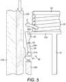
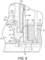
- the dispensing locking members 27 are pivotable from a locked state (shown in Figs. 2 and 3 ) to an unlocked state (shown in Figs. 4 and 6 ).
- a locked state shown in Figs. 2 and 3
- an unlocked state shown in Figs. 4 and 6
- each of the dispensing locking members 27 is positioned such that the elongate member 29 extends towards the end wall 21 of the proximal portion 17 at an angle away from the central axis A-A of the housing 11 in the direction from the first end 29A to the second end 29B of the elongate member 29.
- the dispensing locking members 27 are positioned such that the projections 30 extend towards the end wall 21 of the proximal portion 17 at an angle towards the central axis A-A of the housing 11 in the direction towards the free end 30A of the projection 30.
- the plate 24 When the dispensing locking members 27 are in the locked state, the plate 24 is located in the recesses 29C of the elongate members 29 such that the plate 24 is prevented from moving towards the end wall 19 of the distal portion 16 of the housing 11.
- the configuration of the recesses 29C is such that a portion of each elongate member 29 abuts a radially inwardly facing surface 24C of the plate 24 and therefore, when the dispensing locking members 27 are in the locked state and abut the plate 24, the dispensing locking members 27 are prevented from rotating in a direction wherein the second ends 29B of the elongate members 29 move radially outwardly away from the central axis A-A of the housing 11.
- the dispensing locking members 27 are moveable to the unlocked state, wherein the dispensing locking members 27 are rotated (in the direction of arrow 'B' in Fig. 6 ) such that the second end 29B of each elongate member 29 and the free end 30A of the corresponding projection 30 pivot about the respective pivotal couplings 28 to move radially inwardly towards the central axis A-A of the housing 11.
- the second end 29B of each elongate member 29 is spaced from the plate 24 such that the plate 24 is not received in the recesses 29C of the elongate members 29. Therefore, the plate 24 is not restricted from moving towards the end wall 19 of the distal portion 16 by the dispensing locking members 27.
- the actuator 15 is in the form of a button 15 that has a peripheral wall 15A and an end wall 15B.
- the button 15 is received in the proximal portion 17 of the housing 11 such that the peripheral wall 15A of the button 15 is located on the inside of the internal wall 17A of the proximal portion 17 and is concentrically aligned therewith.
- the button 15 is slidable within the internal wall 17A of the proximal portion 17 in the direction of the central axis A-A of the housing 11.
- the needle 12 is moveable relative to the distal portion 16 of the housing 11 between a retracted position (shown in Figs. 1 to 4 , 8 and 9B ) and an extended position (shown in Figs. 7 and 9A ).
- a retracted position shown in Figs. 1 to 4 , 8 and 9B
- an extended position shown in Figs. 7 and 9A .
- the needle 12 When the needle 12 is moved from the retracted position to the extended position, the needle 12 is moved linearly in the direction of the central axis A-A of the housing 11 such that the end of the needle 12 projects out of an aperture 19C in the end wall 19 of the distal portion 16.
- the needle 12 pierces the patient's skin to extend into the injection site to deliver medicament thereto.
- the medicament delivery device 10 further comprises a septum 31 that is fixed to the inner surface 19B of the end wall 19 of the distal portion 16.
- the septum 31 is located over the aperture 19C in the end wall 19 of the distal portion 16.
- the needle 12, which is initially in the retracted position is protected by the septum 31. More specifically, the septum 31 prevents the ingress of contaminants through the aperture 19C in the end wall 19 of the distal portion 16 and into contact with the sterile needle 12.
- the septum 31 may be manufactured from an impermeable material such as plastic, rubber or metal foil.
- the septum 31 is fixed to the outer surface 19A of the end wall 19 of the distal portion 16 or is located in the aperture 19C in the end wall 19.
- the needle actuating mechanism 13 comprises needle extension and retraction biasing members 32, 33, extension and retraction holding elements 34, 35, and needle extension and retraction locks 36, 37.
- the needle extension biasing member 32 is in the form of a needle extension spring 32.
- the needle extension spring 32 may be a helical spring.
- the needle extension spring 32 is located inside the peripheral wall 15A of the button 15 and extends about the central axis A-A of the housing 11.
- the needle extension spring 32 is disposed between a base 12A of the needle 12 and the extension holding element 34.
- the extension holding element 34 is fixed relative to the distal portion 16 of the housing 11 and is located on the opposite side of the base 12A of the needle 12 to the septum 31.
- the extension holding element 34 is configured to act as a stop against which the proximal end of the needle extension spring 32 abuts such that the proximal end of the needle extension spring 32 is prevented from moving towards the end wall 21 of the proximal portion 17 in the direction of the central axis A-A of the housing 11.
- the needle extension spring 32 When the needle 12 is in the initial retracted position, the needle extension spring 32 is compressed between the base 12A of the needle 12 and the extension holding element 34 such that the needle extension spring 32 urges the needle 12 away from the extension holding element 34 in the direction of the central axis A-A of the housing 11 such that the needle 12 is biased to move into the extended position.
- the needle extension lock 36 comprises a pair of extension locking members 38 that are connected to the distal portion 16 of the housing 11 by respective pivotal couplings 39.
- Each of the extension locking members 38 comprises an elongate member 38A and first and second projections 40, 41 that are integrally formed with the elongate member 38A.
- the first projection 40 is located at the distal end of the elongate member 38A and the second projection 41 is located towards the proximal end of the elongate member 38A.
- Each elongate member 38A is attached to the respective pivotal coupling 39 at a point between the proximal and distal ends of the elongate member 38A such that the first and second projections 40, 41 are pivotable about the respective pivotal coupling 39.
- the extension locking members 38 are moveable from a locked state (shown in Fig. 3 ) to an unlocked state (shown in Fig. 5 ).
- the locked state the extension locking members 38 are positioned such that the elongate members 38A extend substantially parallel to the central axis A-A of the housing 11 and the first projection 40 of each extension locking member 38 is located nearer to the end wall 21 of the proximal portion 17 of the housing 11 than the second projection 41.
- each extension locking member 38 extends radially inwardly towards the central axis A-A of the housing 11 when the extension locking members 38 are in the locked state.
- Each of the first projections 40 comprises a proximal-facing surface 40A that abuts the base 12A of the needle 12 when the extension locking members 38 are in the locked state such that movement of the needle 12 in the direction of the central axis A-A of the housing 11 towards the end wall 19 of the distal portion 16 is prevented.
- the extension locking members 38 retain the needle 12 in the retracted position against the force of the needle extension spring 32, which is held in a compressed state between the base 12A of the needle 12 and the extension holding element 34.
- each extension locking member 38 extends radially outwardly away from the central axis A-A of the housing 11 when the extension locking members 38 are in the locked state.
- Each of the second projections 41 comprises an angled surface 41A that faces at an angle away from the central axis A-A of the housing 11 and towards the end wall 21 of the proximal portion 17.
- the button 15 comprises a lip 15C that extends radially inwardly from the inside of the peripheral wall 15A of the button 15 in the direction towards the central axis A-A of the housing 11.
- the lip 15C may be generally annular.
- the lip 15C of the button 15 is configured to abut the angled surface 41A of both of the extension locking members 38 when the button 15 is moved within the housing 11 towards the end wall 19 of the distal portion 16. This causes the second projection 41 of each extension locking member 38 to be urged radially inwardly towards the central axis A-A such that the extension locking members 38 are rotated from the locked state to the unlocked state (in the direction of arrow 'C' in Fig. 5 ).
- the first projections 40 are moved radially outwardly such that they no longer abut the base 12A of the needle 12 and therefore the base 12A of the needle 12 is able to move away from the extension holding element 34 under the force of the needle extension spring 32.
- the needle 12 moves from the retracted position to the extended position under the force of the needle extension spring 32.
- the needle retraction biasing member 33 is in the form of a needle retraction spring 33.
- the needle retraction spring 33 may be a helical spring.
- the needle retraction spring 33 is located inside the distal portion 16 of the housing 11 and extends about the central axis A-A thereof.
- the needle retraction spring 33 is disposed between the retraction holding element 35 and the septum 31.
- the septum 31 is fixed relative to the distal portion 16 of the housing 11 and therefore acts as a stop against which the distal end of the needle retraction spring 33 abuts.
- the retraction holding element 35 is slidably received in the internal wall 16A of the distal portion 16 of the housing 11.
- the needle retraction spring 33 is initially compressed between the septum 31 and the retraction holding element 35 such that the needle retraction spring 33 urges the retraction holding element 35 away from the septum 31 in the direction of the central axis A-A of the housing 11.
- the needle retraction lock 37 initially retains the retraction holding element 35 in position against the force of the needle retraction spring 33 such that the needle retraction spring 33 is compressed.
- the needle retraction lock 37 comprises a pair of retraction locking members 42 that are connected to the distal portion 16 of the housing 11 by respective pivotal couplings 43.
- Each of the retraction locking members 42 comprises first and second elongate members 44, 45, a recess 46, and a projection 47.
- the first and second elongate members 44, 45 are integrally formed at one end.
- the first and second elongate members 44, 45 extend at an angle to each other.
- the first and second elongate members 44, 45 of each retraction locking member 42 extend substantially perpendicular to each other.
- the first and second elongate members 44, 45 comprise respective free ends 44A, 45B that are remote to the pivotal coupling 43.
- the recess 46 is located at the free end 44A of the first elongate member 44 and the projection 47 is located at the free end 45A of the second elongate member 45.
- the retraction locking members 42 are pivotable from a locked state (shown in Fig. 9A ) to an unlocked state (shown in Fig. 9B ).
- each of the retraction locking members 42 is positioned such that the first elongate members 44 extend radially outwardly away from the central axis A-A of the housing 11 and, in one embodiment, are substantially perpendicular to the central axis A-A of the housing 11.
- the free end 44A of each first elongate member 44 overlaps the plate 24 in the radial direction.
- each of the retraction locking members 42 is positioned such that the second elongate members 45 extend towards the end wall 21 of the proximal portion 17 from the respective pivotal coupling 43 and, in one embodiment, are substantially parallel to the central axis A-A of the housing 11.
- each retraction locking member 42 When the retraction locking members 42 are in the locked state, the projection 47 of each retraction locking member 42 extends radially inwardly towards the central axis A-A of the housing 11 to abut a proximal-facing surface of the retraction holding element 35.
- the retraction holding element 35 is prevented from moving towards the end wall 21 of the proximal portion 17 and thus the needle retraction spring 33 is held in a compressed state between the septum 31 and the retraction holding element 35.
- the movement of the plate 24 towards the end wall 19 of the distal portion 16 results in a force being exerted on the free end 44A of each first elongate member 44.
- each retraction locking member 42 is urged to rotate about a respective pivotal coupling 43 from the locked state to the unlocked state (in the direction of arrow 'D' in Fig. 9B ).
- each second elongate member 45 When the retraction locking members 42 are rotated to the unlocked state, the projection 47 at the free end 45A of each second elongate member 45 is moved radially outwardly away from the central axis A-A of the housing 11 such that the projections 47 are spaced from the retraction holding element 35.
- the projections 47 no longer hold the retraction holding element 35 in place against the force of the needle retraction spring 33 and so the retraction holding element 35 is moved towards the end wall 21 of the proximal end 17 by the needle retraction spring 33.
- the needle 12 extends through an aperture 35A in the retraction holding element 35 such that when the needle 12 is in the extended position and the retraction locking members 42 are in the locked state (as shown in Fig. 9A ) the base 12A of the needle 12 is located in proximity to the retraction holding element 35.
- the retraction holding element 35 is released such that the needle retraction spring 33 urges the retraction holding element 35 against the base 12A of the needle 12 to move the needle 12 towards the end wall 21 of the proximal portion 17 and into the retracted position (as shown in Fig. 9B ).
- a clearance gap (not shown) may be provided between each retraction locking member 42 and the septum 31 and end wall 19 of the distal portion 16 to facilitate movement of the retraction locking members 42 between the locked and unlocked states.
- the septum 31 may be manufactured from a flexible material that facilitates movement of the retraction locking members 42.
- the medicament delivery device 10 further comprises a coupling 48 between the distal and proximal portions 16, 17 of the housing 11.
- the coupling 48 is configured to resist the proximal portion 17 from being moving away from the primed position towards the initial position.
- the coupling 48 may be configured to prevent the force of the dispensing spring 25, which is located between the plate 24 and the end wall 21 of the proximal portion 17, from moving the end wall 21 of the proximal portion 17 away from the end wall 19 of the distal portion 16 when the proximal portion 17 is in the primed position.
- the coupling 48 is in the form of a latch 48.
- the latch 48 comprises first, second and third stops 49, 50, 51.
- the first stop 49 is in the form of a first lip 49 that is integrally formed with the peripheral wall 20 of the proximal portion 17 of the housing 11.
- the first lip 49 extends radially inwardly towards the central axis A-A of the housing 11.
- the first lip 49 extends from the end of the peripheral wall 20 of the proximal portion 17 that is remote to the end wall 21 of the proximal portion 17.
- the first lip 49 comprises a proximal-facing surface 49A.
- the second stop 50 is in the form of a second lip 50 that is integrally formed with the peripheral wall 18 of the distal portion 16.
- the second lip 50 extends radially outwardly away from the central axis A-A of the housing 11.
- the second lip 50 extends from the end of the peripheral wall 18 of the distal portion 16 that is remote to the end wall 19 of the distal portion 16.
- the second lip 50 comprises a distal-facing surface 50A.
- the proximal-facing surface 49A of the first lip 49 abuts the distal-facing surface 50A of the second lip 50 to limit the range of axial movement between the proximal portion 17 and the distal portion 16 such that the proximal portion 17 is prevented from moving away from the distal portion 16 and being separated therefrom.
- the third stop 51 is in the form of a recess 51 that extends into the outer surface of the peripheral wall 18 of the distal portion 16.
- a distal-facing surface 51A is formed at the edge of the recess 51.
- the latch 48 further comprises an angled surface 52 that extends between the distal-facing surface 50A of the second stop 50 and the distal-facing surface 51A of the third stop 51.
- the angled surface 52 is angled slightly with respect to the central axis A-A of the housing 11 such that the angled surface 52 extends slightly away from the central axis A-A of the housing in the direction from the second stop 50 to the third stop 51.
- the angled surface 52 is formed from a portion of the outer surface of the peripheral wall 18 of the distal portion 16.
- the angled surface 52 is configured such that when the proximal portion 17 is moved from the initial position to the primed position the first lip 49 moves over the angled surface 52 and is urged radially outwardly by the angled surface 52 such that the first lip 49 is urged away from the central axis A-A of the housing 11.
- the thickness and material of the proximal portion 17 is such that when the first lip 49 moves over the angled surface 52 the peripheral wall 20 of the proximal portion 17 resiliently deforms radially outwardly. This flexing of the peripheral wall 20 facilitates movement of the first lip 49 over the angled surface 52.
- the distal portion 16 may also have a thickness and/or be manufactured from a material that allows for the peripheral wall 18 of the distal portion 16 to flex radially inwardly as the first lip 49 moves over the angled surface 52.
- the distal and proximal portions 16, 17 may be manufactured from, for example, plastic or metal.
- Movement of the proximal portion 17 from the initial positon to the primed position causes the first lip 49 to move over the angled surface 52 from the second lip 50 towards the recess 51.
- the first lip 49 moves radially inwardly to 'snap' into the recess 51 such that the proximal-facing surface 49A of the first lip 49 abuts the distal-facing surface 51A at the edge of the recess 51.
- the proximal portion 17 is held in place in the primed position such that the end wall 21 of the proximal portion 17 is resisted from moving away from the end wall 19 of the distal portion 16.
- the angled surface 52 is arranged to provide a small amount of resistance to the first lip 49 moving over the angled surface 52 from the second lip 50 towards the recess 51, due to the first lip 49 being urged radially outwardly when the proximal portion 17 is moved towards the primed position. Therefore, the patient must overcome a small amount of resistance to move the proximal portion 17 relative to the distal portion 16 from the initial position to the primed position. This reduces the likelihood of the proximal portion 17 being accidentally moved to the primed position.
- the medicament delivery device 10 is typically stored in a sterile packaging (not shown).
- the patient first removes the medicament delivery device 10 from the sterile packaging.
- the proximal portion 17 of the housing 11 is in the initial position, the needle 12 is in the retracted position, and the button 15 is retracted into the proximal portion 17 (as shown in Fig. 1 ) such that the patient is not able to access the button 15 to actuate the button 15.
- the inner dimension of the internal wall 17A of the proximal portion 17 may be sufficiently small that the patient is not able to insert a finger into the internal wall 17A to access the button 15.
- the patient is not able to depress the button 15 to operate the dispensing mechanism 14 to dispense medicament from the flexible bag 23 and thus the dispensing mechanism 14 is rendered inoperable.
- the patient is not able to operate the needle actuating mechanism 13 to move the needle 12 to the extended position.
- the patient then supplies medicament to the dispensing mechanism 14 of the medicament delivery device 10. More specifically, the patient supplies medicament to the flexible bag 23 via the filling port 18A in the peripheral wall 18 of the distal portion 16 of the housing 11.
- the medicament may be supplied from, for example, a syringe, container, or pressurised canister.
- the medicament reservoir 23 is pre-filled with medicament, in which case the filling port 18A may be omitted.
- the label (not shown) is then removed from the adhesive layer (not shown) on the outer surface 19A of the end wall 19 of the distal portion 16.
- the adhesive layer is then adhered to the patient's skin at the injection site such that the end wall 19 of the distal portion 16 is secured to the injection site.
- the patient then applies a force to the proximal portion 17 of the housing 11 to move the proximal portion 17 from the initial position to the primed position.
- the patient may use one hand to apply a force to the outer surface 21A of the distal wall 21 of the proximal portion 17 to push said distal wall 21 towards the distal wall 19 of the distal portion 16.
- the dispensing spring 25 is compressed between the inner surface 21B of the distal wall 21 of the proximal portion 17 and the proximal facing surface 24B of the plate 24 such that a biasing force is exerted on the plate 24 that urges the plate 24 towards the end wall 19 of the distal portion 16.
- the dispensing locking members 27 are initially in the locked state to hold the plate 24 in position against the force of the dispensing spring 25.
- the first stop 49 engages with the third stop 51 such that the proximal portion 17 is retained in the primed position.
- the engagement between the first and third stops 49, 51 is such to prevent the proximal portion 17 from moving away from the primed position under the force of the dispensing spring 25. Therefore, once the patient has moved the proximal portion 17 to the primed position the patient no longer needs to apply a force to the end wall 21 of the proximal portion 17 to retain the proximal portion 17 in the primed position.
- the button 15 is received in the internal wall 17A of the proximal portion 17 of the housing 11 such that when the proximal portion 17 is moved to the primed position the proximal portion 17 slides relative to the button 15. This causes the button 15 to project from the proximal portion 17 (as shown in Fig. 2 ). Therefore, the button 15 may be actuated by the patient.
- the button 15 projects from the end wall 21 of the proximal portion 17 when the proximal portion 17 is in the primed position.
- the medicament delivery device 10 is primed for supplying medicament to the injection site of the patient.
- the patient depresses the end wall 15B of the button 15 such that the button 15 is slid into the proximal portion 17 of the housing 11.
- This causes the button 15 to engage with the needle extension lock 36 such that the needle extension spring 32 is released to move the needle 12 to the extended position.
- the button 15 is slid towards the end wall 19 of the distal portion 16 until the projection 15C of the button 15 is urged against the angled surface 41A of the second projection 41 of each extension locking member 38, resulting in each extension locking member 38 rotating from the locked state (shown in Fig. 3 ) to the unlocked state (shown in Fig.
- a conduit (not shown) is provided that is fluidly connected to the inside of the flexible bag 23.
- the needle 12 comprises an aperture (not shown) that aligns with the conduit to fluidly communicate therewith when the needle 12 is moved to the extended position such that medicament is able to flow out of the flexible bag 23, through the conduit, and into the aperture of the needle 12 to be dispensed from the needle 12.
- the patient continues to push the button 15 into the housing 11 to then engage the button 15 with the dispensing lock 26 such that, after the needle 12 has been moved to the extended position, the dispensing spring 25 is released to urge the plate 24 towards the end wall 19 of the distal portion 16 such that medicament is dispensed from the flexible bag 23.
- the distal end of the button 15 is urged against the free end 30A of the projection 30 of each dispensing locking member 27, resulting in each dispensing locking member 27 rotating from the locked state (shown in Fig. 3 ) to the unlocked state (shown in Fig. 6 ).
- this allows the plate 24 to move towards the end wall 19 of the distal portion 16 under the force of the dispensing spring 25. Therefore, the flexible bag 23 is compressed between the plate 24 and the end wall 19 of the distal portion 16 such that the pressure of the medicament in the flexible bag 23 is increased and therefore the medicament flows out of the flexible bag 23 and flows through the needle 12 to enter the injection site of the patient.
- the patient may stop pressing the button 15.
- the plate 24 will continue to move towards the end wall 19 of the distal portion 16 such that the flexible bag 23 is compressed and thus medicament is delivered to the injection site of the patient via the needle 12. Therefore, the medicament delivery device 10 may be used to deliver medicament to the injection site of the patient over an extended time period, for example, several hours, without requiring the patient to continuously apply a force to the button 15.
- Medicament will continue to be delivered to the injection site until the plate 24 moves to a position within the housing 11 wherein the plate 24 engages with the needle retraction lock 37 such that the needle retraction spring 33 is released to move the needle 12 to the retracted position.
- the plate 24 is moved towards the end wall 19 of the distal portion 16 under the force of the dispensing spring 25 until the plate 24 is urged against the free end 44A of each first elongate member 44 of the retraction locking members 42, resulting in each retraction locking member 42 rotating from the locked state (shown in Fig. 9A ) to the unlocked state (shown in Fig. 9B ).
- this allows the retraction holding element 35 to move away from the end wall 19 of the distal portion 16 under the force of the needle retraction spring 33 such that the retraction holding element 35 is urged against the base 12A of the needle 12 to move the needle 12 into the housing 11 to the retracted position (as shown in Figs. 8 and 9B ).
- the patient may then remove the medicament delivery device 10 from the injection site.
- a lock may be provided to lock the button 15 in position when the proximal portion 17 is in the initial positon.
- the lock may comprise a locking member that is in a locked state when the proximal portion 17 is in the initial position to prevent movement of the button 15 relative to the housing 11.
- the locking member is moved to an unlocked state when the proximal portion 17 is moved to the primed position such that the button 15 can be moved relative to the housing 11.
- a medicament delivery device 60 according to a second embodiment of the invention is shown.
- the medicament delivery device 60 of the second embodiment of the invention is similar to the medicament delivery device 10 of the first embodiment, with like features retaining the same reference numerals.
- a difference is that the coupling 48 of the medicament delivery device 10 of the first embodiment is omitted and is replaced with an alternative coupling 61.
- the coupling 61 of the medicament delivery device 60 of the second embodiment comprises first and second screw threads 62, 63.
- the first screw thread 62 is formed in the inner surface of the peripheral wall 20 of the proximal portion 17.
- the second screw thread 63 is formed in the outer surface of the peripheral wall 18 of the distal portion 16.
- the first and second screw threads 62, 63 are configured to engage to couple the distal and proximal portions 16, 17 of the housing 11 such that the proximal portion 17 can be screwed to the distal portion 16 of the housing 11. Therefore, the proximal portion 17 is moveable from an initial position (shown in Fig. 10 ), wherein the proximal portion 17 is coupled to the distal portion 16 such that the end walls 19, 21 of the distal and proximal portions 16, 17 are spaced apart, to a primed position (shown in Fig. 11 ), wherein the proximal portion 17 is twisted such that the screw threads 62, 63 engage and thus the end walls 19, 21 of the distal and proximal portions 16, 17 are moved closer together.
- the medicament delivery device 60 of the second embodiment comprises a needle actuating mechanism 13 and a dispensing mechanism 14 that are similar to those of the medicament delivery device 10 of the first embodiment described above.
- the medicament delivery device 60 is typically stored in a sterile packaging (not shown).
- the patient first removes the medicament delivery device 60 from the sterile packaging.
- the proximal portion 17 of the housing 11 is in the initial position, the needle 12 is in the retracted position, and the button 15 is retracted into the proximal portion 17 (as shown in Fig. 10 ) such that the patient is not able to access the button 15 to actuate the button 15.
- the patient is not able to depress the button 15 to operate the dispensing mechanism 14 to dispense medicament from the flexible bag 23 or operate the needle actuating mechanism 13 to move the needle 12 to the extended position.
- the patient then supplies medicament to the flexible bag 23 of the medicament delivery device 60, removes the label (not shown) from the adhesive layer (not shown), and adheres the adhesive layer to the patient's skin such that the end wall 19 of the distal portion 16 is secured to the injection site.
- the patient rotates the proximal portion 17 relative to the distal portion 16 such that the engagement of the first and second screw threads 62, 63 causes the proximal portion 17 to move from the initial position to the primed position. More specifically, the rotation of the proximal portion 17 relative to the distal portion 16 causes the proximal portion 17 to move relative to the distal portion 16 in the direction of the central axis A-A of the housing 11 such that the end wall 21 of the proximal portion 17 moves towards the end wall 19 of the distal portion 16.
- the patient may use one hand to twist the proximal portion 17 relative to the distal portion 16 to move the proximal portion 17 to the primed position.
- the dispensing spring 25 As the proximal portion 17 is moved towards the primed position, the dispensing spring 25 is compressed between the distal wall 21 of the proximal portion 17 and the plate 24 such that the dispensing spring 25 exerts a biasing force on the plate 24 that urges the plate 24 towards the end wall 19 of the distal portion 16.
- the dispensing locking members (not shown) of the dispensing mechanism 14 are initially in the locked state to hold the plate 24 in position against the force of the dispensing spring 25.
- the proximal portion 17 When the proximal portion 17 reaches the primed position, the proximal portion 17 is retained in the primed position by the engagement of the first and second screw threads 62, 63.
- the configuration of the first and second screw threads 62, 63 is such to prevent the proximal portion 17 from moving away from the primed position under the force of the dispensing spring 25. This may be achieved, for example, due to the pitch of the first and second screw threads 62, 63. Therefore, once the patient has moved the proximal portion 17 to the primed position the patient no longer needs to apply a force to the proximal portion 17 to retain the proximal portion 17 in the primed position.
- the actuator 15 protrudes from the end wall 21 of the proximal portion 17 when the proximal portion 17 is in the primed position.
- the remaining operation of the medicament delivery device 60 is the same as that of the medicament delivery device 10 of the first embodiment of the invention and therefore, for the sake of brevity, a detailed description thereof is not repeated hereinafter.
- the patient pushes the button 15 into the proximal portion 17 such that the button 15 engages with the needle extension lock of the needle actuating mechanism 13 such that the needle extension spring is released to move the needle 12 to the extended position.
- the patient further presses the button 15 into the proximal portion 17 until the button 15 engages with the dispensing lock of the dispensing mechanism 14 such that, after the needle 12 has been moved to the extended position, the dispensing spring 25 is released to urge the plate 24 towards the end wall 19 of the distal portion 16. Therefore, medicament is dispensed from the flexible bag 23.
- the patient may then stop pressing the button 15.
- the plate 24 will continue to move towards the end wall 19 of the distal portion 16 such that the flexible bag 23 is compressed to dispense medicament to the injection site of the patient via the needle 12.
- Medicament will continue to be delivered to the injection site until the plate 24 moves to a position within the housing 11 wherein the plate 24 engages with the needle retraction lock of the needle actuating mechanism 13 such that the needle retraction spring is released to move the needle 12 to the retracted position. In this position, the plate 24 is urged against the retraction locking members of the needle retraction lock such that further movement of the plate 24 towards the end wall 19 of the distal portion 16 is prevented. The patient may then remove the medicament delivery device 60 from the injection site.
- one of the first and second screw threads 62, 63 is omitted and is replaced by a protrusion that engages with the other one of the first and second screw threads 62, 63.
- the medicament delivery device 70 comprises a housing 71, a needle 72, a needle actuating mechanism 73, a dispensing mechanism 74, and an actuator 75 in the form of a button 75.
- the housing 71 comprises a distal portion 76 and a proximal portion 77.
- the distal portion 76 comprises a peripheral wall 78 and an end wall 79 and the proximal portion 77 comprises a peripheral wall 80 and an end wall 81.
- the peripheral wall 78 of the distal portion 76 of the housing 71 is slidably received in the peripheral wall 80 of the proximal portion 77 such that the end wall 79 of the distal portion 76 is spaced from the end wall 81 of the proximal portion 77 and a recess 82 is formed therebetween.
- the end wall 79 of the distal portion 76 comprises an adhesive layer (not shown) that is initially covered by a label (not shown). In use, the label is removed from the adhesive layer and then the adhesive layer is stuck to the injection site of the patient such that the end wall 79 of the distal portion 76 is adhered to the injection site.
- the dispensing mechanism 74 comprises a medicament reservoir 83, a dispensing member 84, a dispensing biasing member 85 and a dispensing lock (not shown).
- the medicament reservoir 83 is in the form of rigid container 83.
- the rigid container 83 may be a cylinder 83.
- the dispensing member 84 is in the form of a plunger 84 that is slidably received in the cylinder 83.
- the dispensing biasing member 85 is in the form of a dispensing spring 85.
- the dispensing spring 85 extends between the plunger 84 and the end wall 81 of the proximal portion 77.
- the dispensing spring 85 is configured to urge the plunger 84 to slide in the cylinder 83 towards the end wall 79 of the distal portion 76 to dispense medicament from the cylinder 83.
- the proximal portion 77 is moveable relative to the distal portion 76 of the housing 71 between an initial position (shown in Fig. 12 ) and a primed position (shown in Figs. 13 to 16 ).
- the end wall 81 of the proximal portion 77 is spaced from the plunger 84 such that the dispensing spring 85 is substantially uncompressed.
- the end wall 81 of the proximal portion 77 is moved towards the end wall 79 of the distal portion 76 such that the distance between said end walls 79, 81 is reduced.
- the distance between the plunger 84 and the end wall 81 of the proximal portion 77 is also reduced such that the dispensing spring 85 is compressed therebetween.
- the dispensing mechanism 74 comprises a dispensing lock (not shown) that is configured to retain the plunger 84 in position relative to the cylinder 83 against the force of the dispensing spring 85.
- the dispensing lock of the medicament delivery device 70 of the third embodiment is similar to the dispensing lock 26 of the medicament delivery device 10 of the first embodiment and therefore, for the sake of brevity, a detailed description of the dispensing lock will not be repeated hereinafter.
- the dispensing lock comprises a locking member (not shown) that is moveable from a locked state, wherein the plunger 84 in held in position relative to the cylinder 83 against the force of the dispensing spring 85, to an unlocked state, wherein the plunger 84 is able to move in the cylinder 83 .
- the needle 72 is slidable relative to the distal portion 76 of the housing 71 between a retracted position (shown in Figs. 12, 13 and 16 ), wherein the needle 72 is fully received within the housing 71, and an extended position (shown in Figs. 14 and 15 ), wherein the needle 72 projects from the end wall 79 of the distal portion 76 of the housing 71.
- the needle actuating mechanism 73 of the medicament delivery device 70 of the third embodiment is similar to the needle actuating mechanism 13 of the medicament delivery device 10 of the first embodiment and so a detailed description will not be repeated hereinafter.
- the needle actuating mechanism 73 includes needle extension and retraction springs, extension and retraction holding elements, and needle extension and retraction locks that are configured in a similar manner to those of the first embodiment.
- the needle extension and retraction locks may comprise corresponding locking members that are moveable from a locked state, wherein the respective extension and retraction springs are held in a compressed position, to an unlocked state, wherein the respective extension and retraction springs are released.
- the medicament delivery device 70 is typically stored in a sterile packaging (not shown).
- the patient first removes the medicament delivery device 70 from the sterile packaging.
- the proximal portion 77 of the housing 71 is in the initial position, the needle 72 is in the retracted position, and the button 75 is retracted into the proximal portion 77 (as shown in Fig. 12 ) such that the patient is not able to access the button 75 to actuate the button 75.
- the patient is not able to depress the button 75 to operate the dispensing mechanism 74 to dispense medicament from the medicament reservoir 83 or to operate the needle actuating mechanism 73 to move the needle 72 to the extended position.
- the medicament reservoir 84 may be pre-filled with medicament or may be filled by the patient via a filling port (not shown).
- the patient removes the label (not shown) from the adhesive layer (not shown), and adheres the adhesive layer to the patient's skin such that the end wall 79 of the distal portion 76 is secured to the injection site.
- the patient urges the end wall 81 the proximal portion 77 towards to the end wall 19 of the distal portion 76 such that the proximal portion 77 moves from the initial position to the primed position.
- the dispensing spring 85 is compressed between the plunger 84 and the distal wall 81 of the proximal portion 77 such that a biasing force is exerted on the plunger 84 that biases the plunger 84 to move within the cylinder 83 towards the end wall 79 of the distal portion 76.
- the plunger 84 is initially held in position relative to the cylinder 83 by the needle extension lock (not shown).
- the proximal portion 77 When the proximal portion 77 reaches the primed position, the proximal portion 77 is retained in the primed position by a coupling, for example, a latch (not shown).
- the coupling comprises a pair of engaging screw threads.
- the button 75 protrudes from the end wall 81 of the proximal portion 77 when the proximal portion 77 is in the primed position.
- a passage 72B in the base 72A of the needle 72 aligns with a conduit 86 extending from an outlet 83A in the cylinder 83.
- the passage 72B is fluidly communicated with the conduit 86.
- the patient continues to depress the button 75 until the button 75 engages with the dispensing lock (not shown) such that, after the needle 72 has been moved to the extended position, the dispensing spring 85 is released to urge the plunger 84 towards the end wall 79 of the distal portion 76.
- This causes the plunger 84 to move within the cylinder 83 to dispense medicament from the cylinder 83 (as shown in Fig. 15 ).
- the medicament flows from the outlet 83A in the cylinder 83 and into the conduit 86.
- the medicament flows through the conduit 86 and enters the passage 72B in the needle 72 wherein the medicament flows through the needle 72 to the injection site of the patient.
- the patient may then stop pressing the button 75.
- the plunger 84 will continue to move within the cylinder 83 under the force of the dispensing spring 85 to dispense medicament from the cylinder 83. Medicament will continue to be delivered to the injection site until the plunger 84 moves to a position within the cylinder 83 wherein the plunger 84 engages with the needle retraction lock (not shown) such that the needle retraction spring is released to move the needle 72 to the retracted position (as shown in Fig. 16 ). The patient may then remove the medicament delivery device 70 from the injection site.
- the needle extension and retraction springs 32, 33 are pre-compressed such that the springs 32, 33 are in a compressed state prior to the proximal portion 17, 77 of the housing 11, 71 being moved to the primed position.
- the needle extension and retraction springs 32, 33 are in a substantially uncompressed state when the proximal portion 17, 77 is in the initial position and movement of the proximal portion 17, 77 to the primed position compresses the extension and retraction springs 32, 33.
- extension holding element 34 may instead be fixed relative to the proximal portion 17, 77 such that movement of the proximal portion 17, 77 from the initial position to the primed position moves the extension holding element 34 towards the end wall 19, 79 of the distal portion 16, 76.
- the needle extension spring 32 is compressed between the extension holding element 34 and the base 12A, 72A of the needle 12, 72.
- the proximal portion 17, 77 is moved from the initial position to the primed position to compress the dispensing spring 25, 85, in an alternative embodiment (not shown) the dispensing spring 25, 85 is pre-compressed.
- the actuator 15, 75 is fully received within the housing 11, 71 when the proximal portion 17, 77 is in the initial position.
- the actuator 15, 75 is configured to project from the proximal portion 17, 77 of the housing 11, 71 when the proximal portion 17, 77 is in the initial and primed positions.
- the actuator 15, 75 is of sufficient length to project from the end wall 21, 81 of the proximal portion 17, 77 when the proximal portion 17, 77 is in the initial position.
- the dispensing biasing member 25, 85 and the needle extension and retraction biasing members 32, 33 comprise respective springs 25, 85 32, 33.
- one or more of the dispensing biasing member 25, 85, the needle extension biasing member 32 and the needle retraction biasing member 33 comprise a different type of biasing member, for example, a portion of resiliently deformable material that is compressed to exert a biasing force.
- the needle 12, 72 is moveable relative to the housing 11, 71 between the retracted and extended positions.
- the needle 12, 72 is fixed in the extended position such that the needle 12, 72 permanently projects from the housing 11, 71.
- the dispensing lock 26 is mechanically operated, the end of the button 15, 75 being urged against the dispensing locking members 27 to rotate the dispensing locking members 27 from the locked state to the unlocked state.
- the dispensing lock 26 is electrically operated.
- the dispensing lock may comprise an electromagnetic latch (not shown) that holds the dispensing member 24, 84 in position relative to the distal portion 16, 76 of the housing 11, 71.
- the electromagnetic latch changes state such that the dispensing member 24, 84 is released to move towards the end wall 19, 79 of the distal portion 16, 76 under the force of the dispensing spring 25, 85.
- the needle actuating mechanism 13, 73 may instead be electrically operated, for example, comprising a motor (not shown) that moves the needle 12, 72 between the retracted and extended positions.
- the dispensing mechanism 14, 74 comprises a dispensing member 24, 84 and a dispensing biasing member 25, 85 configured to urge the dispensing member 24, 84 to move relative to the housing 11 to expel medicament from the reservoir 23, 83.
- the dispensing mechanism may have a different arrangement.
- the dispensing mechanism comprises a pump that is operable to pump medicament from the reservoir to deliver the medicament to the needle. For example, when the actuator is in the primed position, the patient may actuate the actuator to operate the pump to deliver medicament from the reservoir.
- the reservoir comprises a barrel for containing medicament, wherein operation of the dispensing mechanism moves a plunger within the barrel to dispense medicament from the barrel, wherein the plunger is moved relative to the barrel by a drive mechanism, for example, an electric motor or a hydraulic or pneumatic drive mechanism.
- the motor may be a linear motor or may be a rotary motor that drives a rack and pinion gear assembly to move the plunger relative to the barrel.
- actuation of the actuator may close a switch to operate the dispensing mechanism, for example, to operate a motor of a pump to dispense medicament from the reservoir or to operate a drive mechanism to move a plunger.
- actuation of the actuator may be detected by a sensor, for example, a proximity sensor, wherein the dispensing mechanism is operated upon detection of actuation of the actuator.
- a drug or medicament can include at least one small or large molecule, or combinations thereof, in various types of formulations, for the treatment of one or more diseases.
- exemplary pharmaceutically active compounds may include small molecules; polypeptides, peptides and proteins (e.g., hormones, growth factors, antibodies, antibody fragments, and enzymes); carbohydrates and polysaccharides; and nucleic acids, double or single stranded DNA (including naked and cDNA), RNA, antisense nucleic acids such as antisense DNA and RNA, small interfering RNA (siRNA), ribozymes, genes, and oligonucleotides. Nucleic acids may be incorporated into molecular delivery systems such as vectors, plasmids, or liposomes. Mixtures of one or more of these drugs are also contemplated.
- a drug delivery device shall encompass any type of device or system configured to dispense a drug into a human or animal body.
- a drug delivery device may be an injection device (e.g., syringe, pen injector, auto injector, large-volume device, pump, perfusion system, or other device configured for intraocular, subcutaneous, intramuscular, or intravascular delivery), skin patch (e.g., osmotic, chemical, micro-needle), inhaler (e.g., nasal or pulmonary), implantable (e.g., coated stent, capsule), or feeding systems for the gastrointestinal tract.
- the presently described drugs may be particularly useful with injection devices that include a needle, e.g., a small gauge needle.
- the drug or medicament may be contained in a primary package or "drug container" adapted for use with a drug delivery device.
- the drug container may be, e.g., a cartridge, syringe, reservoir, or other vessel configured to provide a suitable chamber for storage (e.g., short- or long-term storage) of one or more pharmaceutically active compounds.
- the chamber may be designed to store a drug for at least one day (e.g., 1 to at least 30 days).
- the chamber may be designed to store a drug for about 1 month to about 2 years. Storage may occur at room temperature (e.g., about 20°C), or refrigerated temperatures (e.g., from about - 4°C to about 4°C).
- the drug container may be or may include a dual-chamber cartridge configured to store two or more components of a drug formulation (e.g., a drug and a diluent, or two different types of drugs) separately, one in each chamber.
- the two chambers of the dual-chamber cartridge may be configured to allow mixing between the two or more components of the drug or medicament prior to and/or during dispensing into the human or animal body.
- the two chambers may be configured such that they are in fluid communication with each other (e.g., by way of a conduit between the two chambers) and allow mixing of the two components when desired by a user prior to dispensing.
- the two chambers may be configured to allow mixing as the components are being dispensed into the human or animal body.
- the drug delivery devices and drugs described herein can be used for the treatment and/or prophylaxis of many different types of disorders.
- exemplary disorders include, e.g., diabetes mellitus or complications associated with diabetes mellitus such as diabetic retinopathy, thromboembolism disorders such as deep vein or pulmonary thromboembolism.
- Further exemplary disorders are acute coronary syndrome (ACS), angina, myocardial infarction, cancer, macular degeneration, inflammation, hay fever, atherosclerosis and/or rheumatoid arthritis.
- ACS acute coronary syndrome
- angina myocardial infarction
- cancer macular degeneration
- inflammation hay fever
- atherosclerosis and/or rheumatoid arthritis.
- Exemplary drugs for the treatment and/or prophylaxis of diabetes mellitus or complications associated with diabetes mellitus include an insulin, e.g., human insulin, or a human insulin analogue or derivative, a glucagon-like peptide (GLP-1), GLP-1 analogues or GLP-1 receptor agonists, or an analogue or derivative thereof, a dipeptidyl peptidase-4 (DPP4) inhibitor, or a pharmaceutically acceptable salt or solvate thereof, or any mixture thereof.
- the term "derivative” refers to any substance which is sufficiently structurally similar to the original substance so as to have substantially similar functionality or activity (e.g., therapeutic effectiveness).
- Exemplary insulin analogues are Gly(A21), Arg(B31), Arg(B32) human insulin (insulin glargine); Lys(B3), Glu(B29) human insulin; Lys(B28), Pro(B29) human insulin; Asp(B28) human insulin; human insulin, wherein proline in position B28 is replaced by Asp, Lys, Leu, Val or Ala and wherein in position B29 Lys may be replaced by Pro; Ala(B26) human insulin; Des(B28-B30) human insulin; Des(B27) human insulin and Des(B30) human insulin.
- Exemplary insulin derivatives are, for example, B29-N-myristoyl-des(B30) human insulin; B29-N-palmitoyl-des(B30) human insulin; B29-N-myristoyl human insulin; B29-N-palmitoyl human insulin; B28-N-myristoyl LysB28ProB29 human insulin; B28-N-palmitoyl-LysB28ProB29 human insulin; B30-N-myristoyl-ThrB29LysB30 human insulin; B30-N-palmitoyl- ThrB29LysB30 human insulin; B29-N-(N-palmitoyl-gamma-glutamyl)-des(B30) human insulin; B29-N-(N-lithocholyl-gamma-glutamyl)-des(B30) human insulin; B29-N-( ⁇ -carboxyheptadecanoyl)-des(B30) human insulin and B29-N
- GLP-1, GLP-1 analogues and GLP-1 receptor agonists are, for example: Lixisenatide / AVE0010 / ZP10 / Lyxumia, Exenatide / Exendin-4 / Byetta / Bydureon / ITCA 650 / AC-2993 (a 39 amino acid peptide which is produced by the salivary glands of the Gila monster), Liraglutide / Victoza, Semaglutide, Taspoglutide, Syncria / Albiglutide, Dulaglutide, rExendin-4, CJC-1134-PC, PB-1023, TTP-054, Langlenatide/ HM-11260C, CM-3, GLP-1 Eligen, ORMD-0901, NN-9924, NN-9926, NN-9927, Nodexen, Viador-GLP-1, CVX-096, ZYOG-1, ZYD-1, GSK-2374697, DA-3091, MAR-701,
- An exemplary oligonucleotide is, for example: mipomersen / Kynamro, a cholesterol-reducing antisense therapeutic for the treatment of familial hypercholesterolemia.
- DPP4 inhibitors are Vildagliptin, Sitagliptin, Denagliptin, Saxagliptin, Berberine.
- hormones include hypophysis hormones or hypothalamus hormones or regulatory active peptides and their antagonists, such as Gonadotropine (Follitropin, Lutropin, Choriongonadotropin, Menotropin), Somatropine (Somatropin), Desmopressin, Terlipressin, Gonadorelin, Triptorelin, Leuprorelin, Buserelin, Nafarelin, and Goserelin.
- Gonadotropine Follitropin, Lutropin, Choriongonadotropin, Menotropin
- Somatropine Somatropin
- Desmopressin Terlipressin
- Gonadorelin Triptorelin
- Leuprorelin Buserelin
- Nafarelin Nafarelin
- Goserelin Goserelin.
- Exemplary polysaccharides include a glucosaminoglycane, a hyaluronic acid, a heparin, a low molecular weight heparin or an ultra-low molecular weight heparin or a derivative thereof, or a sulphated polysaccharide, e.g. a poly-sulphated form of the above-mentioned polysaccharides, and/or a pharmaceutically acceptable salt thereof.
- An example of a pharmaceutically acceptable salt of a poly-sulphated low molecular weight heparin is enoxaparin sodium.
- An example of a hyaluronic acid derivative is Hylan G-F 20 / Synvisc, a sodium hyaluronate.
- antibody refers to an immunoglobulin molecule or an antigen-binding portion thereof.
- antigen-binding portions of immunoglobulin molecules include F(ab) and F(ab')2 fragments, which retain the ability to bind antigen.
- the antibody can be polyclonal, monoclonal, recombinant, chimeric, de-immunized or humanized, fully human, non-human, (e.g., murine), or single chain antibody.
- the antibody has effector function and can fix complement.
- the antibody has reduced or no ability to bind an Fc receptor.
- the antibody can be an isotype or subtype, an antibody fragment or mutant, which does not support binding to an Fc receptor, e.g., it has a mutagenized or deleted Fc receptor binding region.
- fragment refers to a polypeptide derived from an antibody polypeptide molecule (e.g., an antibody heavy and/or light chain polypeptide) that does not comprise a full-length antibody polypeptide, but that still comprises at least a portion of a full-length antibody polypeptide that is capable of binding to an antigen.
- Antibody fragments can comprise a cleaved portion of a full length antibody polypeptide, although the term is not limited to such cleaved fragments.
- Antibody fragments that are useful in the present invention include, for example, Fab fragments, F(ab')2 fragments, scFv (single-chain Fv) fragments, linear antibodies, monospecific or multispecific antibody fragments such as bispecific, trispecific, and multispecific antibodies (e.g., diabodies, triabodies, tetrabodies), minibodies, chelating recombinant antibodies, tribodies or bibodies, intrabodies, nanobodies, small modular immunopharmaceuticals (SMIP), binding-domain immunoglobulin fusion proteins, camelized antibodies, and VHH containing antibodies. Additional examples of antigen-binding antibody fragments are known in the art.
- CDR complementarity-determining region
- framework region refers to amino acid sequences within the variable region of both heavy and light chain polypeptides that are not CDR sequences, and are primarily responsible for maintaining correct positioning of the CDR sequences to permit antigen binding.
- framework regions themselves typically do not directly participate in antigen binding, as is known in the art, certain residues within the framework regions of certain antibodies can directly participate in antigen binding or can affect the ability of one or more amino acids in CDRs to interact with antigen.
- Exemplary antibodies are anti PCSK-9 mAb (e.g., Alirocumab), anti IL-6 mAb (e.g., Sarilumab), and anti IL-4 mAb (e.g., Dupilumab).
- anti PCSK-9 mAb e.g., Alirocumab
- anti IL-6 mAb e.g., Sarilumab
- anti IL-4 mAb e.g., Dupilumab
- the compounds described herein may be used in pharmaceutical formulations comprising (a) the compound(s) or pharmaceutically acceptable salts thereof, and (b) a pharmaceutically acceptable carrier.
- the compounds may also be used in pharmaceutical formulations that include one or more other active pharmaceutical ingredients or in pharmaceutical formulations in which the present compound or a pharmaceutically acceptable salt thereof is the only active ingredient.
- the pharmaceutical formulations of the present disclosure encompass any formulation made by admixing a compound described herein and a pharmaceutically acceptable carrier.
- Pharmaceutically acceptable salts of any drug described herein are also contemplated for use in drug delivery devices.
- Pharmaceutically acceptable salts are for example acid addition salts and basic salts.
- Acid addition salts are e.g. HCI or HBr salts.
- Basic salts are e.g. salts having a cation selected from an alkali or alkaline earth metal, e.g.
- R1 to R4 independently of each other mean: hydrogen, an optionally substituted C1 C6-alkyl group, an optionally substituted C2-C6-alkenyl group, an optionally substituted C6-C10-aryl group, or an optionally substituted C6-C10-heteroaryl group.
- R1 to R4 independently of each other mean: hydrogen, an optionally substituted C1 C6-alkyl group, an optionally substituted C2-C6-alkenyl group, an optionally substituted C6-C10-aryl group, or an optionally substituted C6-C10-heteroaryl group.
- solvates are for example hydrates or alkanolates such as methanolates or ethanlates.
Description
- The present invention relates to a medicament delivery device.
- A variety of diseases exist that require regular treatment by injection of a medicament and such injections can be performed by using injection devices. Various injection devices for delivering injections of medicament are known in the art. Another type of injection pump that is gaining traction is the bolus injector device. Some bolus injector devices are intended to be used with relatively large volumes of medicament, typically at least 1 ml and maybe a few ml. Injection of such large volumes of medicament can take some minutes or even hours. Such high capacity bolus injector devices can be called large volume devices (LVDs). Generally such devices are operated by the patients themselves, although they may also be operated by medical personnel.
-
WO 92/11879 A1 -
US 2011/306929 A1 discloses a fluid delivery device including an automatic needle retraction mechanism configured to automatically retract a delivery end of a needle into a housing. The needle assembly may be configured to automatically withdraw the delivery end of the needle into the housing upon an actuator moving from the first position to the second position. The needle assembly may be configured to automatically withdraw the delivery end of the needle into the housing upon decoupling a bottom surface of the housing from a skin surface. -
WO 2011/101376 A1 discloses a clutch mechanism for the transmission of a rotary movement from a gear arrangement comprising a first gear member and a second gear member. The first gear member is rotatable about a longitudinal axis but axially fixed wherein the first gear member, upon rotation, is arranged for moving a second gear member which is prevented from rotating. The clutch mechanism comprises a circumferential shoulder arranged at the second gear member and at least one or a number of resilient clutch fingers with respective inclined inner surfaces arranged at the first gear member, the shoulder arranged for increasingly pressing against the inclined surfaces thereby flexing the clutch fingers outward when the shoulder reaches the clutch fingers in the course of its translation. The clutch mechanism further comprises tube arranged around the clutch fingers, the tube having a number of internal longitudinal splines for engaging the flexed-out clutch fingers. - It is an object of the present invention to provide an improved medicament delivery device.
- According to the present invention, there is provided a medicament delivery device comprising: a housing having first and second portions; a dispensing mechanism that comprises a reservoir disposed in the housing, wherein the dispensing mechanism is operable to dispense medicament from the reservoir when the reservoir contains medicament; and, an actuator, wherein the first portion of the housing comprises a distal end and the second portion is moveable towards the distal end from an initial position, wherein actuation of the actuator is impeded such that the dispensing mechanism is rendered inoperable, to a primed position, wherein the actuator is actuatable to operate the dispensing mechanism, wherein the actuator is retracted into the housing when the second portion is in the initial position to prevent actuation of the actuator and protrudes out of the housing when the second portion is in the primed position.
- Advantageously, such a configuration makes it clear to the patient whether the second portion is in the initial or primed position and prevents the patient from trying to force operation of the actuator.
- Advantageously, when the second portion of the housing is in the initial position the patient is prevented from accidentally operating the dispensing mechanism. The patient is able to easily render the actuator actuatable to enable operation of the dispensing mechanism by moving the second portion of the housing towards the first portion of the housing.
- In one embodiment, the dispensing mechanism further comprises a dispensing member and a biasing member configured to urge the dispensing member to move in a first direction relative to the housing to expel medicament from the reservoir when the reservoir contains medicament.
- In one embodiment, the biasing member is configured to resiliently deform when the second portion of the housing is moved from the initial position to the primed position such that the biasing member exerts a biasing force on the dispensing member to urge the dispensing member in the first direction. Thus, the biasing member only needs to be primed immediately before use, rather than being stored in resiliently deformed state which may otherwise result in degradation of the biasing member over time causing a reduction in the biasing force.
- In one embodiment, the medicament delivery device comprises a dispensing lock that is moveable between a locked state, wherein the dispensing member is held in position relative to the housing against the biasing force of the biasing member, and an unlocked state, wherein the dispensing member is able to move in the first direction.
- The actuator may comprise a push button. The medicament delivery device may comprise a needle that is configured to protrude from the distal end of the first portion.
- In one embodiment, the first and second portions of the housing comprise respective peripheral walls, and wherein the peripheral wall of one of the first and second portions is configured to be received within the peripheral wall of the other one of the first and second portions.
- In one embodiment, the housing is configured such that the second portion is slidable relative to the first portion from the initial position to the primed position. This sliding motion of the second portion may be easy for the patient to perform, which is particularly advantageous if the patient is elderly or infirm.
- In one embodiment, at least one of the first and second portions comprises a screw thread.
- In one embodiment, the medicament delivery device comprises a latch configured to resist movement of the second portion relative to the first portion from the primed position to the initial position. This helps to prevent the actuator from being accidentally rendered operable.
- In one embodiment, the first and/or second portion of the housing comprises a filling port for supplying the reservoir with medicament.
- The reservoir may contain medicament.
- In one embodiment, the distal end of the first portion of the housing comprises an adhesive layer. Therefore, the first portion may be attached to an injection site of the patient.
- In one embodiment, the second portion comprises a proximal end wall and, preferably, the proximal end wall has a substantially flat surface.
- In one embodiment, the first portion of the housing comprises a proximal end that is remote to the distal end.
- In one embodiment, the reservoir is located between the first and second portions of the housing.
- In one embodiment, the actuator is at least partially received in the second portion of the housing. The actuator may be moveably mounted to the second portion of the housing. The actuator may be slidably mounted to the second portion of the housing. The actuator may be retracted into the second portion of the housing when the second portion of the housing is in the initial position.
- In one embodiment, the first and second portions of the housing define a chamber that receives the dispensing mechanism.
- According to the present invention, there is also provided a method of preparing a medicament delivery device comprising a housing having first and second portions, a dispensing mechanism that comprises a reservoir disposed in the housing, and an actuator, the method comprising: positioning a distal end of the first portion in proximity to an injection site of a patient; and, moving the second portion towards the distal end of the first portion from an initial position, wherein actuation of the actuator is impeded such that operation of the dispensing mechanism is prevented, to a primed position, wherein the actuator is moveable relative to the housing to operate the dispensing mechanism to dispense medicament from the reservoir to the injection site, wherein the actuator is retracted into the housing when the second portion is in the initial position to prevent actuation of the actuator and protrudes out of the housing when the second portion is in the primed position.
- These and other aspects of the invention will be apparent from and elucidated with reference to the embodiments described hereinafter.
- Embodiments of the invention will now be described, by way of example only, with reference to the accompanying drawings, in which:
-
Fig. 1 is a schematic cross-sectional side view of a medicament delivery device according to a first embodiment of the invention, wherein a proximal portion of the housing is in an initial position; -
Fig. 2 is a schematic cross-sectional side view of the medicament delivery device ofFig. 1 , wherein the proximal portion is in a primed position and a button projects from the proximal portion; -
Fig. 3 is a close-up schematic cross-sectional side view of part of the medicament delivery device ofFig. 1 ; -
Fig. 4 is a schematic cross-sectional side view of the medicament delivery device ofFig. 1 , wherein the button is partially depressed into the housing and a needle is in a retracted position; -
Fig. 5 is a close-up schematic cross-sectional side view of a needle extension lock of the medicament delivery device ofFig. 1 , wherein a pair of needle locking members are moved to an unlocked state; -
Fig. 6 is a close-up schematic cross-sectional side view of a dispensing lock of the medicament delivery device ofFig. 1 , wherein a pair of extension locking members are moved to an unlocked state; -
Fig. 7 is a schematic cross-sectional side view of the medicament delivery device ofFig. 1 , wherein the needle is in an extended position and medicament is dispensed from the needle; -
Fig. 8 is a schematic cross-sectional side view of the medicament delivery device ofFig. 1 , wherein the needle is in the retracted position; -
Fig. 9A is a close-up schematic cross-sectional side view of a needle retraction lock of the medicament delivery device ofFig. 1 , wherein a pair of retraction locking members are in a locked state; -
Fig. 9B is a close-up schematic cross-sectional side view of the needle retraction lock of the medicament delivery device ofFig. 1 , wherein the pair of retraction locking members are in an unlocked state; -
Fig. 10 is a schematic cross-sectional side view of a medicament delivery device according to a second embodiment of the invention, wherein a proximal portion of the housing is in an initial position; -
Fig. 11 is a schematic cross-sectional side view of the medicament delivery device ofFig. 10 , wherein the proximal portion is in a primed position and a button projects from the proximal portion; -
Fig. 12 is a schematic cross-sectional side view of a medicament delivery device according to a third embodiment of the invention, wherein a proximal portion of the housing is in an initial position; -
Fig. 13 is a schematic cross-sectional side view of the medicament delivery device ofFig. 12 , wherein the proximal portion is in a primed position and a button projects from the proximal portion; -
Fig. 14 is a schematic cross-sectional side view of the medicament delivery device ofFig. 12 , wherein the button is depressed into the housing and a needle is in an extended position; -
Fig. 15 is a schematic cross-sectional side view of the medicament delivery device ofFig. 12 , wherein the needle is in the extended position and medicament is dispensed from the needle; and, -
Fig. 16 is a schematic cross-sectional side view of the medicament delivery device ofFig. 12 , wherein the needle is in the retracted position. - A medicament delivery device, as described herein, may be configured to inject a medicament into a patient. For example, delivery could be sub-cutaneous, intra-muscular, or intravenous. Such a device could be operated by a patient or care-giver, such as a nurse or physician, and can include various types of safety syringe, pen-injector, or auto-injector. The device can include a cartridge-based system that requires piercing a sealed ampule before use. Volumes of medicament delivered with these various devices can range from about 0.5 ml to about 2 ml. Yet another device can include a large volume device ("LVD") or patch pump, configured to adhere to a patient's skin for a period of time (e.g., about 5, 15, 30, 60, or 120 minutes) to deliver a "large" volume of medicament (typically about 2 ml to about 10 ml).
- In combination with a specific medicament, the presently described devices may also be customized in order to operate within required specifications. For example, the device may be customized to inject a medicament within a certain time period (e.g., about 3 to about 20 seconds for auto-injectors, and about 10 minutes to about 60 minutes for a large volume device). Other specifications can include a low or minimal level of discomfort, or to certain conditions related to human factors, shelf-life, expiry, biocompatibility, environmental considerations, etc. Such variations can arise due to various factors, such as, for example, a drug ranging in viscosity from about 3 cP to about 50 cP. Consequently, a drug delivery device will often include a hollow needle ranging from about 25 to about 31 Gauge in size. Common sizes are 27 and 29 Gauge.
-
Figs. 1 to 9B show amedicament delivery device 10, which in the exemplary embodiment comprises a bolus injector device, according to a first embodiment of the invention. Themedicament delivery device 10 may be in the form of a large volume device. - The
medicament delivery device 10 comprises ahousing 11, aneedle 12, aneedle actuating mechanism 13, adispensing mechanism 14 and anactuator 15. - The
housing 11 comprises adistal portion 16 and aproximal portion 17. The term "distal" refers to a location that is relatively closer to a site of injection and the term "proximal" refers to a location that is relatively further away from the injection site. - The
distal portion 16 of thehousing 11 comprises a cylindricalperipheral wall 18 and anend wall 19 that together have a generally U-shaped cross-section. Thedistal portion 16 of thehousing 11 further comprises a cylindricalinternal wall 16A that is arranged concentrically with the cylindricalperipheral wall 18 of thedistal portion 16. Theproximal portion 17 of thehousing 11 comprises a cylindricalperipheral wall 20 and anend wall 21 that together have a generally U-shaped cross-section. Theproximal portion 17 of thehousing 11 comprises a cylindricalinternal wall 17A that is arranged concentrically with the cylindricalperipheral wall 20 of theproximal portion 17. - The
peripheral wall 18 of thedistal portion 16 of thehousing 11 is slidably received in theperipheral wall 20 of theproximal portion 17 such that theend wall 19 of thedistal portion 16 is spaced from theend wall 21 of theproximal portion 17 and arecess 22 is formed therebetween. The distal andproximal portions housing 11 together form a generally cylindrical shape that has a central axis (see the dashed line A-A inFig. 2 ). - The
end wall 19 of thedistal portion 16 has anouter surface 19A and aninner surface 19B and theend wall 21 of theproximal portion 17 has anouter surface 21 A and aninner surface 21B. One or both of theouter surfaces end walls proximal portions - The
outer surface 19A of theend wall 19 of thedistal portion 16 comprises an adhesive layer (not shown) that is initially covered by a label (not shown). In use, the label is removed from the adhesive layer and then the adhesive layer is stuck to the patient's skin at the injection site of the patient such that theend wall 19 of thedistal portion 16 is adhered to the injection site. - The
dispensing mechanism 14 comprises amedicament reservoir 23, a dispensingmember 24, adispensing biasing member 25 and a dispensinglock 26. - The
medicament reservoir 23 is in the form of an annularflexible bag 23. Theflexible bag 23 is disposed in therecess 22 in thehousing 11 and abuts theinner surface 19B of theend wall 19 of thedistal portion 16. Theflexible bag 23 is fluidly connected to anaperture 18A in theperipheral wall 18 of thedistal portion 16. Theaperture 18A forms a fillingport 18A that allows for theflexible bag 23 to be filled with medicament through theperipheral wall 18 of thedistal portion 16. Theflexible bag 23 and/or theaperture 18A may comprise a one-way valve (not shown) that is configured to prevent medicament from flowing out of theflexible bag 23 via theaperture 18A. Alternatively, or additionally, a bung (not shown) may be provided that is inserted into theaperture 18A to seal theaperture 18A after theflexible bag 23 has been filled with medicament. - The dispensing
member 24 is in the form of aplate 24. Theplate 24 may be annular. Theplate 24 is disposed in therecess 22 in thehousing 11 such that theflexible bag 23 is located between a distal-facingsurface 24A of theplate 24 and theinner surface 19B of theend wall 19 of thedistal portion 16. Theplate 24 is slidable in therecess 22 in the direction of the central axis A-A of thehousing 11 such that theplate 24 is moveable relative toflexible bag 23. - The
dispensing biasing member 25 is in the form of a dispensingspring 25. The dispensingspring 25 may be a helical spring. The dispensingspring 25 is disposed in therecess 22 in thehousing 11 and extends about the central axis A-A of thehousing 11. The dispensingspring 25 is positioned between theinternal wall 17A of theproximal portion 17 and theperipheral wall 20 of theproximal portion 17. - The dispensing
spring 25 is disposed on the opposite side of theplate 24 to theflexible bag 23. A first end of the dispensingspring 25 is located against theinner surface 21B of theend wall 21 of theproximal portion 17 and a remote second end of the dispensingspring 25 is located against a proximal-facingsurface 24B of theplate 24. - The
proximal portion 17 is moveable relative to thedistal portion 16 of thehousing 11 between an initial position (shown inFig. 1 ) and a primed position (shown inFigs. 2 ,4 ,7 and 8 ). When theproximal portion 17 is in the initial position, theend wall 21 of theproximal portion 17 is spaced from theplate 24 and theend wall 19 of thedistal portion 16 such that the dispensingspring 25 is substantially uncompressed. Furthermore, when theproximal portion 17 is in the initial position, only a small section of theperipheral wall 18 of thedistal portion 16 is received in theperipheral wall 20 of theproximal portion 17. - When the
proximal portion 17 is moved to the primed position, theend wall 21 of theproximal portion 17 is moved towards theend wall 19 of thedistal portion 16 such that the distance between theend walls peripheral wall 18 of thedistal portion 16 is received in theperipheral wall 20 of theproximal portion 17 when theproximal portion 17 is in the primed position. - The dispensing
lock 26 comprises a pair of dispensing lockingmembers 27 that are connected to thedistal portion 16 of thehousing 11 by correspondingpivotal couplings 28. Each of thedispensing locking members 27 comprises anelongate member 29 and aprojection 30 that is integrally formed with theelongate member 29. - The
elongate members 29 have afirst end 29A and asecond end 29B. Theelongate members 29 are each attached to a correspondingpivotal coupling 28 towards thefirst end 29A of theelongate members 29. Thesecond end 29B of eachelongate member 29 is spaced from the correspondingpivotal coupling 28 such that eachsecond end 29B is pivotable about the correspondingpivotal coupling 28. Arecess 29C is provided in thesecond end 29B of eachelongate member 29. - The
projection 30 of eachdispensing locking member 27 extends at an angle from a correspondingelongate member 29 and is located proximate to thefirst end 29A of theelongate member 29. Eachprojection 30 has afree end 30A that is remote to said correspondingelongate member 29. Theelongate member 29 andprojection 30 may be arranged such that thedispensing locking members 27 are each generally L-shaped or V-shaped. - The
dispensing locking members 27 are pivotable from a locked state (shown inFigs. 2 and3 ) to an unlocked state (shown inFigs. 4 and6 ). In the locked state, each of thedispensing locking members 27 is positioned such that theelongate member 29 extends towards theend wall 21 of theproximal portion 17 at an angle away from the central axis A-A of thehousing 11 in the direction from thefirst end 29A to thesecond end 29B of theelongate member 29. Moreover, in the locked state, thedispensing locking members 27 are positioned such that theprojections 30 extend towards theend wall 21 of theproximal portion 17 at an angle towards the central axis A-A of thehousing 11 in the direction towards thefree end 30A of theprojection 30. - When the
dispensing locking members 27 are in the locked state, theplate 24 is located in therecesses 29C of theelongate members 29 such that theplate 24 is prevented from moving towards theend wall 19 of thedistal portion 16 of thehousing 11. The configuration of therecesses 29C is such that a portion of eachelongate member 29 abuts a radially inwardly facingsurface 24C of theplate 24 and therefore, when thedispensing locking members 27 are in the locked state and abut theplate 24, thedispensing locking members 27 are prevented from rotating in a direction wherein the second ends 29B of theelongate members 29 move radially outwardly away from the central axis A-A of thehousing 11. - The
dispensing locking members 27 are moveable to the unlocked state, wherein thedispensing locking members 27 are rotated (in the direction of arrow 'B' inFig. 6 ) such that thesecond end 29B of eachelongate member 29 and thefree end 30A of the correspondingprojection 30 pivot about the respectivepivotal couplings 28 to move radially inwardly towards the central axis A-A of thehousing 11. When thedispensing locking members 27 are in the unlocked state, thesecond end 29B of eachelongate member 29 is spaced from theplate 24 such that theplate 24 is not received in therecesses 29C of theelongate members 29. Therefore, theplate 24 is not restricted from moving towards theend wall 19 of thedistal portion 16 by thedispensing locking members 27. - The
actuator 15 is in the form of abutton 15 that has aperipheral wall 15A and anend wall 15B. Thebutton 15 is received in theproximal portion 17 of thehousing 11 such that theperipheral wall 15A of thebutton 15 is located on the inside of theinternal wall 17A of theproximal portion 17 and is concentrically aligned therewith. Thebutton 15 is slidable within theinternal wall 17A of theproximal portion 17 in the direction of the central axis A-A of thehousing 11. - The
needle 12 is moveable relative to thedistal portion 16 of thehousing 11 between a retracted position (shown inFigs. 1 to 4 ,8 and9B ) and an extended position (shown inFigs. 7 and9A ). When theneedle 12 is in the retracted position, theneedle 12 is fully received in therecess 22 in thehousing 11 such that theneedle 12 is shielded to prevent damage to theneedle 12 and to protect the patient from being accidentally injured by theneedle 12. - When the
needle 12 is moved from the retracted position to the extended position, theneedle 12 is moved linearly in the direction of the central axis A-A of thehousing 11 such that the end of theneedle 12 projects out of anaperture 19C in theend wall 19 of thedistal portion 16. Thus, when the adhesive layer of thedistal portion 16 is adhered to the injection site of a patient, theneedle 12 pierces the patient's skin to extend into the injection site to deliver medicament thereto. - The
medicament delivery device 10 further comprises aseptum 31 that is fixed to theinner surface 19B of theend wall 19 of thedistal portion 16. Theseptum 31 is located over theaperture 19C in theend wall 19 of thedistal portion 16. Theneedle 12, which is initially in the retracted position, is protected by theseptum 31. More specifically, theseptum 31 prevents the ingress of contaminants through theaperture 19C in theend wall 19 of thedistal portion 16 and into contact with thesterile needle 12. When theneedle 12 is moved to the extended position, theneedle 12 pierces theseptum 31 and the end of theneedle 12 passes through theseptum 31 to project from theend wall 19. Theseptum 31 may be manufactured from an impermeable material such as plastic, rubber or metal foil. In alternative embodiments, theseptum 31 is fixed to theouter surface 19A of theend wall 19 of thedistal portion 16 or is located in theaperture 19C in theend wall 19. - The
needle actuating mechanism 13 comprises needle extension andretraction biasing members retraction holding elements - The needle
extension biasing member 32 is in the form of aneedle extension spring 32. Theneedle extension spring 32 may be a helical spring. Theneedle extension spring 32 is located inside theperipheral wall 15A of thebutton 15 and extends about the central axis A-A of thehousing 11. Theneedle extension spring 32 is disposed between a base 12A of theneedle 12 and theextension holding element 34. - The
extension holding element 34 is fixed relative to thedistal portion 16 of thehousing 11 and is located on the opposite side of thebase 12A of theneedle 12 to theseptum 31. Theextension holding element 34 is configured to act as a stop against which the proximal end of theneedle extension spring 32 abuts such that the proximal end of theneedle extension spring 32 is prevented from moving towards theend wall 21 of theproximal portion 17 in the direction of the central axis A-A of thehousing 11. When theneedle 12 is in the initial retracted position, theneedle extension spring 32 is compressed between the base 12A of theneedle 12 and theextension holding element 34 such that theneedle extension spring 32 urges theneedle 12 away from theextension holding element 34 in the direction of the central axis A-A of thehousing 11 such that theneedle 12 is biased to move into the extended position. - The
needle extension lock 36 comprises a pair ofextension locking members 38 that are connected to thedistal portion 16 of thehousing 11 by respectivepivotal couplings 39. Each of theextension locking members 38 comprises anelongate member 38A and first andsecond projections elongate member 38A. Thefirst projection 40 is located at the distal end of theelongate member 38A and thesecond projection 41 is located towards the proximal end of theelongate member 38A. - Each
elongate member 38A is attached to the respectivepivotal coupling 39 at a point between the proximal and distal ends of theelongate member 38A such that the first andsecond projections pivotal coupling 39. - The
extension locking members 38 are moveable from a locked state (shown inFig. 3 ) to an unlocked state (shown inFig. 5 ). In the locked state, theextension locking members 38 are positioned such that theelongate members 38A extend substantially parallel to the central axis A-A of thehousing 11 and thefirst projection 40 of eachextension locking member 38 is located nearer to theend wall 21 of theproximal portion 17 of thehousing 11 than thesecond projection 41. - The
first projection 40 of eachextension locking member 38 extends radially inwardly towards the central axis A-A of thehousing 11 when theextension locking members 38 are in the locked state. Each of thefirst projections 40 comprises a proximal-facingsurface 40A that abuts thebase 12A of theneedle 12 when theextension locking members 38 are in the locked state such that movement of theneedle 12 in the direction of the central axis A-A of thehousing 11 towards theend wall 19 of thedistal portion 16 is prevented. Thus, when theextension locking members 38 are in the locked state, theextension locking members 38 retain theneedle 12 in the retracted position against the force of theneedle extension spring 32, which is held in a compressed state between the base 12A of theneedle 12 and theextension holding element 34. - The
second projection 41 of eachextension locking member 38 extends radially outwardly away from the central axis A-A of thehousing 11 when theextension locking members 38 are in the locked state. Each of thesecond projections 41 comprises an angled surface 41A that faces at an angle away from the central axis A-A of thehousing 11 and towards theend wall 21 of theproximal portion 17. - The
button 15 comprises alip 15C that extends radially inwardly from the inside of theperipheral wall 15A of thebutton 15 in the direction towards the central axis A-A of thehousing 11. Thelip 15C may be generally annular. - The
lip 15C of thebutton 15 is configured to abut the angled surface 41A of both of theextension locking members 38 when thebutton 15 is moved within thehousing 11 towards theend wall 19 of thedistal portion 16. This causes thesecond projection 41 of eachextension locking member 38 to be urged radially inwardly towards the central axis A-A such that theextension locking members 38 are rotated from the locked state to the unlocked state (in the direction of arrow 'C' inFig. 5 ). In the unlocked state, thefirst projections 40 are moved radially outwardly such that they no longer abut thebase 12A of theneedle 12 and therefore thebase 12A of theneedle 12 is able to move away from theextension holding element 34 under the force of theneedle extension spring 32. Thus, when theextension locking members 38 are in the unlocked state, theneedle 12 moves from the retracted position to the extended position under the force of theneedle extension spring 32. - The needle
retraction biasing member 33 is in the form of aneedle retraction spring 33. Theneedle retraction spring 33 may be a helical spring. Theneedle retraction spring 33 is located inside thedistal portion 16 of thehousing 11 and extends about the central axis A-A thereof. Theneedle retraction spring 33 is disposed between theretraction holding element 35 and theseptum 31. Theseptum 31 is fixed relative to thedistal portion 16 of thehousing 11 and therefore acts as a stop against which the distal end of theneedle retraction spring 33 abuts. - The
retraction holding element 35 is slidably received in theinternal wall 16A of thedistal portion 16 of thehousing 11. Theneedle retraction spring 33 is initially compressed between theseptum 31 and theretraction holding element 35 such that theneedle retraction spring 33 urges theretraction holding element 35 away from theseptum 31 in the direction of the central axis A-A of thehousing 11. Theneedle retraction lock 37 initially retains theretraction holding element 35 in position against the force of theneedle retraction spring 33 such that theneedle retraction spring 33 is compressed. - The
needle retraction lock 37 comprises a pair ofretraction locking members 42 that are connected to thedistal portion 16 of thehousing 11 by respectivepivotal couplings 43. Each of theretraction locking members 42 comprises first and secondelongate members recess 46, and aprojection 47. The first and secondelongate members elongate members elongate members retraction locking member 42 extend substantially perpendicular to each other. - The first and second
elongate members free ends 44A, 45B that are remote to thepivotal coupling 43. Therecess 46 is located at thefree end 44A of the firstelongate member 44 and theprojection 47 is located at thefree end 45A of the secondelongate member 45. - The
retraction locking members 42 are pivotable from a locked state (shown inFig. 9A ) to an unlocked state (shown inFig. 9B ). In the locked state, each of theretraction locking members 42 is positioned such that the firstelongate members 44 extend radially outwardly away from the central axis A-A of thehousing 11 and, in one embodiment, are substantially perpendicular to the central axis A-A of thehousing 11. Thefree end 44A of each firstelongate member 44 overlaps theplate 24 in the radial direction. Moreover, in the locked state, each of theretraction locking members 42 is positioned such that the secondelongate members 45 extend towards theend wall 21 of theproximal portion 17 from the respectivepivotal coupling 43 and, in one embodiment, are substantially parallel to the central axis A-A of thehousing 11. - When the
retraction locking members 42 are in the locked state, theprojection 47 of eachretraction locking member 42 extends radially inwardly towards the central axis A-A of thehousing 11 to abut a proximal-facing surface of theretraction holding element 35. Thus, theretraction holding element 35 is prevented from moving towards theend wall 21 of theproximal portion 17 and thus theneedle retraction spring 33 is held in a compressed state between theseptum 31 and theretraction holding element 35. - Movement of the
plate 24 within thehousing 11 towards theend wall 19 of thedistal portion 16, due to operation of thedispensing mechanism 14, causes theplate 24 to be urged against thefree end 44A of each firstelongate member 44 such that theplate 24 is received in therecess 46 of each firstelongate member 44. Thus, the movement of theplate 24 towards theend wall 19 of thedistal portion 16 results in a force being exerted on thefree end 44A of each firstelongate member 44. This force causes thefree end 44A of each firstelongate member 44 to be urged towards theend wall 19 of thedistal portion 16 such that eachretraction locking member 42 is urged to rotate about a respectivepivotal coupling 43 from the locked state to the unlocked state (in the direction of arrow 'D' inFig. 9B ). - When the
retraction locking members 42 are rotated to the unlocked state, theprojection 47 at thefree end 45A of each secondelongate member 45 is moved radially outwardly away from the central axis A-A of thehousing 11 such that theprojections 47 are spaced from theretraction holding element 35. Thus, theprojections 47 no longer hold theretraction holding element 35 in place against the force of theneedle retraction spring 33 and so theretraction holding element 35 is moved towards theend wall 21 of theproximal end 17 by theneedle retraction spring 33. - The
needle 12 extends through anaperture 35A in theretraction holding element 35 such that when theneedle 12 is in the extended position and theretraction locking members 42 are in the locked state (as shown inFig. 9A ) thebase 12A of theneedle 12 is located in proximity to theretraction holding element 35. Thus, when theretraction locking members 42 are subsequently moved to the unlocked state, theretraction holding element 35 is released such that theneedle retraction spring 33 urges theretraction holding element 35 against thebase 12A of theneedle 12 to move theneedle 12 towards theend wall 21 of theproximal portion 17 and into the retracted position (as shown inFig. 9B ). - A clearance gap (not shown) may be provided between each
retraction locking member 42 and theseptum 31 andend wall 19 of thedistal portion 16 to facilitate movement of theretraction locking members 42 between the locked and unlocked states. Alternatively, theseptum 31 may be manufactured from a flexible material that facilitates movement of theretraction locking members 42. - The
medicament delivery device 10 further comprises acoupling 48 between the distal andproximal portions housing 11. Thecoupling 48 is configured to resist theproximal portion 17 from being moving away from the primed position towards the initial position. Thecoupling 48 may be configured to prevent the force of the dispensingspring 25, which is located between theplate 24 and theend wall 21 of theproximal portion 17, from moving theend wall 21 of theproximal portion 17 away from theend wall 19 of thedistal portion 16 when theproximal portion 17 is in the primed position. - The
coupling 48 is in the form of alatch 48. Thelatch 48 comprises first, second andthird stops first stop 49 is in the form of afirst lip 49 that is integrally formed with theperipheral wall 20 of theproximal portion 17 of thehousing 11. Thefirst lip 49 extends radially inwardly towards the central axis A-A of thehousing 11. Thefirst lip 49 extends from the end of theperipheral wall 20 of theproximal portion 17 that is remote to theend wall 21 of theproximal portion 17. Thefirst lip 49 comprises a proximal-facingsurface 49A. - The
second stop 50 is in the form of asecond lip 50 that is integrally formed with theperipheral wall 18 of thedistal portion 16. Thesecond lip 50 extends radially outwardly away from the central axis A-A of thehousing 11. Thesecond lip 50 extends from the end of theperipheral wall 18 of thedistal portion 16 that is remote to theend wall 19 of thedistal portion 16. Thesecond lip 50 comprises a distal-facingsurface 50A. - When the
proximal portion 17 of thehousing 11 is in the initial position (as shown inFig. 1 ), the proximal-facingsurface 49A of thefirst lip 49 abuts the distal-facingsurface 50A of thesecond lip 50 to limit the range of axial movement between theproximal portion 17 and thedistal portion 16 such that theproximal portion 17 is prevented from moving away from thedistal portion 16 and being separated therefrom. - The
third stop 51 is in the form of arecess 51 that extends into the outer surface of theperipheral wall 18 of thedistal portion 16. A distal-facing surface 51A is formed at the edge of therecess 51. - The
latch 48 further comprises an angled surface 52 that extends between the distal-facingsurface 50A of thesecond stop 50 and the distal-facing surface 51A of thethird stop 51. The angled surface 52 is angled slightly with respect to the central axis A-A of thehousing 11 such that the angled surface 52 extends slightly away from the central axis A-A of the housing in the direction from thesecond stop 50 to thethird stop 51. The angled surface 52 is formed from a portion of the outer surface of theperipheral wall 18 of thedistal portion 16. - The angled surface 52 is configured such that when the
proximal portion 17 is moved from the initial position to the primed position thefirst lip 49 moves over the angled surface 52 and is urged radially outwardly by the angled surface 52 such that thefirst lip 49 is urged away from the central axis A-A of thehousing 11. The thickness and material of theproximal portion 17 is such that when thefirst lip 49 moves over the angled surface 52 theperipheral wall 20 of theproximal portion 17 resiliently deforms radially outwardly. This flexing of theperipheral wall 20 facilitates movement of thefirst lip 49 over the angled surface 52. Similarly, thedistal portion 16 may also have a thickness and/or be manufactured from a material that allows for theperipheral wall 18 of thedistal portion 16 to flex radially inwardly as thefirst lip 49 moves over the angled surface 52. The distal andproximal portions - Movement of the
proximal portion 17 from the initial positon to the primed position causes thefirst lip 49 to move over the angled surface 52 from thesecond lip 50 towards therecess 51. When thefirst lip 49 reaches therecess 51, thefirst lip 49 moves radially inwardly to 'snap' into therecess 51 such that the proximal-facingsurface 49A of thefirst lip 49 abuts the distal-facing surface 51A at the edge of therecess 51. Thus, theproximal portion 17 is held in place in the primed position such that theend wall 21 of theproximal portion 17 is resisted from moving away from theend wall 19 of thedistal portion 16. - The angled surface 52 is arranged to provide a small amount of resistance to the
first lip 49 moving over the angled surface 52 from thesecond lip 50 towards therecess 51, due to thefirst lip 49 being urged radially outwardly when theproximal portion 17 is moved towards the primed position. Therefore, the patient must overcome a small amount of resistance to move theproximal portion 17 relative to thedistal portion 16 from the initial position to the primed position. This reduces the likelihood of theproximal portion 17 being accidentally moved to the primed position. - An exemplary operation of the
medicament delivery device 10 will now be described. Themedicament delivery device 10 is typically stored in a sterile packaging (not shown). The patient first removes themedicament delivery device 10 from the sterile packaging. When themedicament delivery device 10 is removed from the sterile packaging theproximal portion 17 of thehousing 11 is in the initial position, theneedle 12 is in the retracted position, and thebutton 15 is retracted into the proximal portion 17 (as shown inFig. 1 ) such that the patient is not able to access thebutton 15 to actuate thebutton 15. For example, the inner dimension of theinternal wall 17A of theproximal portion 17 may be sufficiently small that the patient is not able to insert a finger into theinternal wall 17A to access thebutton 15. Thus, the patient is not able to depress thebutton 15 to operate thedispensing mechanism 14 to dispense medicament from theflexible bag 23 and thus thedispensing mechanism 14 is rendered inoperable. Moreover, the patient is not able to operate theneedle actuating mechanism 13 to move theneedle 12 to the extended position. - The patient then supplies medicament to the
dispensing mechanism 14 of themedicament delivery device 10. More specifically, the patient supplies medicament to theflexible bag 23 via the fillingport 18A in theperipheral wall 18 of thedistal portion 16 of thehousing 11. The medicament may be supplied from, for example, a syringe, container, or pressurised canister. In an alternative embodiment, themedicament reservoir 23 is pre-filled with medicament, in which case the fillingport 18A may be omitted. - The label (not shown) is then removed from the adhesive layer (not shown) on the
outer surface 19A of theend wall 19 of thedistal portion 16. The adhesive layer is then adhered to the patient's skin at the injection site such that theend wall 19 of thedistal portion 16 is secured to the injection site. - The patient then applies a force to the
proximal portion 17 of thehousing 11 to move theproximal portion 17 from the initial position to the primed position. For example, the patient may use one hand to apply a force to theouter surface 21A of thedistal wall 21 of theproximal portion 17 to push saiddistal wall 21 towards thedistal wall 19 of thedistal portion 16. As theproximal portion 17 is moved towards the primed position, the dispensingspring 25 is compressed between theinner surface 21B of thedistal wall 21 of theproximal portion 17 and the proximal facingsurface 24B of theplate 24 such that a biasing force is exerted on theplate 24 that urges theplate 24 towards theend wall 19 of thedistal portion 16. However, thedispensing locking members 27 are initially in the locked state to hold theplate 24 in position against the force of the dispensingspring 25. - When the
proximal portion 17 reaches the primed position, thefirst stop 49 engages with thethird stop 51 such that theproximal portion 17 is retained in the primed position. The dispensingspring 25, which is compressed, urges thedistal wall 21 of theproximal portion 17 away from theplate 24 when theproximal portion 17 is in the primed position such that theproximal portion 17 is biased away from the primed position by the force of the dispensingspring 25. However, the engagement between the first andthird stops proximal portion 17 from moving away from the primed position under the force of the dispensingspring 25. Therefore, once the patient has moved theproximal portion 17 to the primed position the patient no longer needs to apply a force to theend wall 21 of theproximal portion 17 to retain theproximal portion 17 in the primed position. - The
button 15 is received in theinternal wall 17A of theproximal portion 17 of thehousing 11 such that when theproximal portion 17 is moved to the primed position theproximal portion 17 slides relative to thebutton 15. This causes thebutton 15 to project from the proximal portion 17 (as shown inFig. 2 ). Therefore, thebutton 15 may be actuated by the patient. Thebutton 15 projects from theend wall 21 of theproximal portion 17 when theproximal portion 17 is in the primed position. - With the
proximal portion 17 in the primed position, themedicament delivery device 10 is primed for supplying medicament to the injection site of the patient. The patient depresses theend wall 15B of thebutton 15 such that thebutton 15 is slid into theproximal portion 17 of thehousing 11. This causes thebutton 15 to engage with theneedle extension lock 36 such that theneedle extension spring 32 is released to move theneedle 12 to the extended position. In more detail, thebutton 15 is slid towards theend wall 19 of thedistal portion 16 until theprojection 15C of thebutton 15 is urged against the angled surface 41A of thesecond projection 41 of eachextension locking member 38, resulting in eachextension locking member 38 rotating from the locked state (shown inFig. 3 ) to the unlocked state (shown inFig. 5 ). As discussed above, this allows thebase 12A of theneedle 12 to move away from theextension holding element 34 under the force of theneedle extension spring 32 such that theneedle 12 moves axially to pass through theseptum 31 to extend out of theaperture 19C in theend wall 19 of thedistal portion 16. Thus, theneedle 12 is moved to the extended position (as shown inFig. 7 ). Theend wall 19 of thedistal portion 16 is adhered to the patient's skin and therefore when theneedle 12 is moved to the extended position theneedle 12 enters the injection site of the patient. - When the
needle 12 is moved to the extended position theneedle 12 is fluidly communicated with the inside of theflexible bag 23. In one embodiment, a conduit (not shown) is provided that is fluidly connected to the inside of theflexible bag 23. Theneedle 12 comprises an aperture (not shown) that aligns with the conduit to fluidly communicate therewith when theneedle 12 is moved to the extended position such that medicament is able to flow out of theflexible bag 23, through the conduit, and into the aperture of theneedle 12 to be dispensed from theneedle 12. - The patient continues to push the
button 15 into thehousing 11 to then engage thebutton 15 with the dispensinglock 26 such that, after theneedle 12 has been moved to the extended position, the dispensingspring 25 is released to urge theplate 24 towards theend wall 19 of thedistal portion 16 such that medicament is dispensed from theflexible bag 23. More specifically, the distal end of thebutton 15 is urged against thefree end 30A of theprojection 30 of eachdispensing locking member 27, resulting in eachdispensing locking member 27 rotating from the locked state (shown inFig. 3 ) to the unlocked state (shown inFig. 6 ). As discussed above, this allows theplate 24 to move towards theend wall 19 of thedistal portion 16 under the force of the dispensingspring 25. Therefore, theflexible bag 23 is compressed between theplate 24 and theend wall 19 of thedistal portion 16 such that the pressure of the medicament in theflexible bag 23 is increased and therefore the medicament flows out of theflexible bag 23 and flows through theneedle 12 to enter the injection site of the patient. - Once the
button 15 has been depressed to the extent that thedispensing locking members 27 are moved to the unlocked state to commence medicament delivery, the patient may stop pressing thebutton 15. Theplate 24 will continue to move towards theend wall 19 of thedistal portion 16 such that theflexible bag 23 is compressed and thus medicament is delivered to the injection site of the patient via theneedle 12. Therefore, themedicament delivery device 10 may be used to deliver medicament to the injection site of the patient over an extended time period, for example, several hours, without requiring the patient to continuously apply a force to thebutton 15. - Medicament will continue to be delivered to the injection site until the
plate 24 moves to a position within thehousing 11 wherein theplate 24 engages with theneedle retraction lock 37 such that theneedle retraction spring 33 is released to move theneedle 12 to the retracted position. In more detail, theplate 24 is moved towards theend wall 19 of thedistal portion 16 under the force of the dispensingspring 25 until theplate 24 is urged against thefree end 44A of each firstelongate member 44 of theretraction locking members 42, resulting in eachretraction locking member 42 rotating from the locked state (shown inFig. 9A ) to the unlocked state (shown inFig. 9B ). As discussed above, this allows theretraction holding element 35 to move away from theend wall 19 of thedistal portion 16 under the force of theneedle retraction spring 33 such that theretraction holding element 35 is urged against thebase 12A of theneedle 12 to move theneedle 12 into thehousing 11 to the retracted position (as shown inFigs. 8 and9B ). The patient may then remove themedicament delivery device 10 from the injection site. - In one embodiment (not shown), a lock may be provided to lock the
button 15 in position when theproximal portion 17 is in the initial positon. The lock may comprise a locking member that is in a locked state when theproximal portion 17 is in the initial position to prevent movement of thebutton 15 relative to thehousing 11. The locking member is moved to an unlocked state when theproximal portion 17 is moved to the primed position such that thebutton 15 can be moved relative to thehousing 11. - Referring now to
Figs. 10 and 11 , amedicament delivery device 60 according to a second embodiment of the invention is shown. Themedicament delivery device 60 of the second embodiment of the invention is similar to themedicament delivery device 10 of the first embodiment, with like features retaining the same reference numerals. A difference is that thecoupling 48 of themedicament delivery device 10 of the first embodiment is omitted and is replaced with analternative coupling 61. - The
coupling 61 of themedicament delivery device 60 of the second embodiment comprises first andsecond screw threads first screw thread 62 is formed in the inner surface of theperipheral wall 20 of theproximal portion 17. Thesecond screw thread 63 is formed in the outer surface of theperipheral wall 18 of thedistal portion 16. - The first and
second screw threads proximal portions housing 11 such that theproximal portion 17 can be screwed to thedistal portion 16 of thehousing 11. Therefore, theproximal portion 17 is moveable from an initial position (shown inFig. 10 ), wherein theproximal portion 17 is coupled to thedistal portion 16 such that theend walls proximal portions Fig. 11 ), wherein theproximal portion 17 is twisted such that thescrew threads end walls proximal portions - The
medicament delivery device 60 of the second embodiment comprises aneedle actuating mechanism 13 and adispensing mechanism 14 that are similar to those of themedicament delivery device 10 of the first embodiment described above. - An exemplary operation of the
medicament delivery device 60 will now be described. Themedicament delivery device 60 is typically stored in a sterile packaging (not shown). The patient first removes themedicament delivery device 60 from the sterile packaging. When themedicament delivery device 60 is removed from the sterile packaging theproximal portion 17 of thehousing 11 is in the initial position, theneedle 12 is in the retracted position, and thebutton 15 is retracted into the proximal portion 17 (as shown inFig. 10 ) such that the patient is not able to access thebutton 15 to actuate thebutton 15. Thus, the patient is not able to depress thebutton 15 to operate thedispensing mechanism 14 to dispense medicament from theflexible bag 23 or operate theneedle actuating mechanism 13 to move theneedle 12 to the extended position. - The patient then supplies medicament to the
flexible bag 23 of themedicament delivery device 60, removes the label (not shown) from the adhesive layer (not shown), and adheres the adhesive layer to the patient's skin such that theend wall 19 of thedistal portion 16 is secured to the injection site. - When the patient wishes to commence the injection, the patient rotates the
proximal portion 17 relative to thedistal portion 16 such that the engagement of the first andsecond screw threads proximal portion 17 to move from the initial position to the primed position. More specifically, the rotation of theproximal portion 17 relative to thedistal portion 16 causes theproximal portion 17 to move relative to thedistal portion 16 in the direction of the central axis A-A of thehousing 11 such that theend wall 21 of theproximal portion 17 moves towards theend wall 19 of thedistal portion 16. The patient may use one hand to twist theproximal portion 17 relative to thedistal portion 16 to move theproximal portion 17 to the primed position. - As the
proximal portion 17 is moved towards the primed position, the dispensingspring 25 is compressed between thedistal wall 21 of theproximal portion 17 and theplate 24 such that the dispensingspring 25 exerts a biasing force on theplate 24 that urges theplate 24 towards theend wall 19 of thedistal portion 16. However, the dispensing locking members (not shown) of thedispensing mechanism 14 are initially in the locked state to hold theplate 24 in position against the force of the dispensingspring 25. - When the
proximal portion 17 reaches the primed position, theproximal portion 17 is retained in the primed position by the engagement of the first andsecond screw threads spring 25, which is compressed, urges thedistal wall 21 of theproximal portion 17 away from theplate 24 when theproximal portion 17 is in the primed position such that theproximal portion 17 is biased away from the primed position by the force of the dispensingspring 25. However, the configuration of the first andsecond screw threads proximal portion 17 from moving away from the primed position under the force of the dispensingspring 25. This may be achieved, for example, due to the pitch of the first andsecond screw threads proximal portion 17 to the primed position the patient no longer needs to apply a force to theproximal portion 17 to retain theproximal portion 17 in the primed position. - The
actuator 15 protrudes from theend wall 21 of theproximal portion 17 when theproximal portion 17 is in the primed position. - The remaining operation of the
medicament delivery device 60 is the same as that of themedicament delivery device 10 of the first embodiment of the invention and therefore, for the sake of brevity, a detailed description thereof is not repeated hereinafter. Briefly, when theproximal portion 17 is in the primed position, the patient pushes thebutton 15 into theproximal portion 17 such that thebutton 15 engages with the needle extension lock of theneedle actuating mechanism 13 such that the needle extension spring is released to move theneedle 12 to the extended position. The patient further presses thebutton 15 into theproximal portion 17 until thebutton 15 engages with the dispensing lock of thedispensing mechanism 14 such that, after theneedle 12 has been moved to the extended position, the dispensingspring 25 is released to urge theplate 24 towards theend wall 19 of thedistal portion 16. Therefore, medicament is dispensed from theflexible bag 23. The patient may then stop pressing thebutton 15. Theplate 24 will continue to move towards theend wall 19 of thedistal portion 16 such that theflexible bag 23 is compressed to dispense medicament to the injection site of the patient via theneedle 12. - Medicament will continue to be delivered to the injection site until the
plate 24 moves to a position within thehousing 11 wherein theplate 24 engages with the needle retraction lock of theneedle actuating mechanism 13 such that the needle retraction spring is released to move theneedle 12 to the retracted position. In this position, theplate 24 is urged against the retraction locking members of the needle retraction lock such that further movement of theplate 24 towards theend wall 19 of thedistal portion 16 is prevented. The patient may then remove themedicament delivery device 60 from the injection site. - In an alternative embodiment, one of the first and
second screw threads second screw threads - Referring now to
Figs. 12 to 16 , aninjection device 70 according to a third embodiment of the invention is shown. Themedicament delivery device 70 comprises ahousing 71, aneedle 72, aneedle actuating mechanism 73, adispensing mechanism 74, and anactuator 75 in the form of abutton 75. - The
housing 71 comprises adistal portion 76 and aproximal portion 77. Thedistal portion 76 comprises aperipheral wall 78 and anend wall 79 and theproximal portion 77 comprises aperipheral wall 80 and anend wall 81. Theperipheral wall 78 of thedistal portion 76 of thehousing 71 is slidably received in theperipheral wall 80 of theproximal portion 77 such that theend wall 79 of thedistal portion 76 is spaced from theend wall 81 of theproximal portion 77 and arecess 82 is formed therebetween. Theend wall 79 of thedistal portion 76 comprises an adhesive layer (not shown) that is initially covered by a label (not shown). In use, the label is removed from the adhesive layer and then the adhesive layer is stuck to the injection site of the patient such that theend wall 79 of thedistal portion 76 is adhered to the injection site. - The
dispensing mechanism 74 comprises amedicament reservoir 83, a dispensingmember 84, adispensing biasing member 85 and a dispensing lock (not shown). - The
medicament reservoir 83 is in the form ofrigid container 83. Therigid container 83 may be acylinder 83. The dispensingmember 84 is in the form of aplunger 84 that is slidably received in thecylinder 83. - The
dispensing biasing member 85 is in the form of a dispensingspring 85. The dispensingspring 85 extends between theplunger 84 and theend wall 81 of theproximal portion 77. The dispensingspring 85 is configured to urge theplunger 84 to slide in thecylinder 83 towards theend wall 79 of thedistal portion 76 to dispense medicament from thecylinder 83. - The
proximal portion 77 is moveable relative to thedistal portion 76 of thehousing 71 between an initial position (shown inFig. 12 ) and a primed position (shown inFigs. 13 to 16 ). When theproximal portion 77 is in the initial position, theend wall 81 of theproximal portion 77 is spaced from theplunger 84 such that the dispensingspring 85 is substantially uncompressed. When theproximal portion 77 is moved to the primed position, theend wall 81 of theproximal portion 77 is moved towards theend wall 79 of thedistal portion 76 such that the distance between saidend walls plunger 84 and theend wall 81 of theproximal portion 77 is also reduced such that the dispensingspring 85 is compressed therebetween. - The
dispensing mechanism 74 comprises a dispensing lock (not shown) that is configured to retain theplunger 84 in position relative to thecylinder 83 against the force of the dispensingspring 85. The dispensing lock of themedicament delivery device 70 of the third embodiment is similar to the dispensinglock 26 of themedicament delivery device 10 of the first embodiment and therefore, for the sake of brevity, a detailed description of the dispensing lock will not be repeated hereinafter. The dispensing lock comprises a locking member (not shown) that is moveable from a locked state, wherein theplunger 84 in held in position relative to thecylinder 83 against the force of the dispensingspring 85, to an unlocked state, wherein theplunger 84 is able to move in thecylinder 83 . - The
needle 72 is slidable relative to thedistal portion 76 of thehousing 71 between a retracted position (shown inFigs. 12, 13 and16 ), wherein theneedle 72 is fully received within thehousing 71, and an extended position (shown inFigs. 14 and 15 ), wherein theneedle 72 projects from theend wall 79 of thedistal portion 76 of thehousing 71. - The
needle actuating mechanism 73 of themedicament delivery device 70 of the third embodiment is similar to theneedle actuating mechanism 13 of themedicament delivery device 10 of the first embodiment and so a detailed description will not be repeated hereinafter. Briefly, theneedle actuating mechanism 73 includes needle extension and retraction springs, extension and retraction holding elements, and needle extension and retraction locks that are configured in a similar manner to those of the first embodiment. For example, the needle extension and retraction locks may comprise corresponding locking members that are moveable from a locked state, wherein the respective extension and retraction springs are held in a compressed position, to an unlocked state, wherein the respective extension and retraction springs are released. - An exemplary operation of the
medicament delivery device 70 will now be described. Themedicament delivery device 70 is typically stored in a sterile packaging (not shown). The patient first removes themedicament delivery device 70 from the sterile packaging. When themedicament delivery device 70 is removed from the sterile packaging theproximal portion 77 of thehousing 71 is in the initial position, theneedle 72 is in the retracted position, and thebutton 75 is retracted into the proximal portion 77 (as shown inFig. 12 ) such that the patient is not able to access thebutton 75 to actuate thebutton 75. Thus, the patient is not able to depress thebutton 75 to operate thedispensing mechanism 74 to dispense medicament from themedicament reservoir 83 or to operate theneedle actuating mechanism 73 to move theneedle 72 to the extended position. Themedicament reservoir 84 may be pre-filled with medicament or may be filled by the patient via a filling port (not shown). - The patient removes the label (not shown) from the adhesive layer (not shown), and adheres the adhesive layer to the patient's skin such that the
end wall 79 of thedistal portion 76 is secured to the injection site. - When the patient wishes to commence the injection, the patient urges the
end wall 81 theproximal portion 77 towards to theend wall 19 of thedistal portion 76 such that theproximal portion 77 moves from the initial position to the primed position. As theproximal portion 77 is moved towards the primed position, the dispensingspring 85 is compressed between theplunger 84 and thedistal wall 81 of theproximal portion 77 such that a biasing force is exerted on theplunger 84 that biases theplunger 84 to move within thecylinder 83 towards theend wall 79 of thedistal portion 76. However, theplunger 84 is initially held in position relative to thecylinder 83 by the needle extension lock (not shown). - When the
proximal portion 77 reaches the primed position, theproximal portion 77 is retained in the primed position by a coupling, for example, a latch (not shown). In another embodiment (not shown), the coupling comprises a pair of engaging screw threads. Thebutton 75 protrudes from theend wall 81 of theproximal portion 77 when theproximal portion 77 is in the primed position. - When the
proximal portion 77 is in the primed position, the patient pushes thebutton 75 into theproximal portion 77 to engage thebutton 75 with the needle extension lock (not shown) such that the needle extension spring is released to move theneedle 72 to the extended position (as shown inFig. 14 ). When theneedle 72 moves to the extended position, apassage 72B in thebase 72A of theneedle 72 aligns with aconduit 86 extending from anoutlet 83A in thecylinder 83. Thus, thepassage 72B is fluidly communicated with theconduit 86. The patient continues to depress thebutton 75 until thebutton 75 engages with the dispensing lock (not shown) such that, after theneedle 72 has been moved to the extended position, the dispensingspring 85 is released to urge theplunger 84 towards theend wall 79 of thedistal portion 76. This causes theplunger 84 to move within thecylinder 83 to dispense medicament from the cylinder 83 (as shown inFig. 15 ). The medicament flows from theoutlet 83A in thecylinder 83 and into theconduit 86. The medicament flows through theconduit 86 and enters thepassage 72B in theneedle 72 wherein the medicament flows through theneedle 72 to the injection site of the patient. The patient may then stop pressing thebutton 75. Theplunger 84 will continue to move within thecylinder 83 under the force of the dispensingspring 85 to dispense medicament from thecylinder 83. Medicament will continue to be delivered to the injection site until theplunger 84 moves to a position within thecylinder 83 wherein theplunger 84 engages with the needle retraction lock (not shown) such that the needle retraction spring is released to move theneedle 72 to the retracted position (as shown inFig. 16 ). The patient may then remove themedicament delivery device 70 from the injection site. - In the above described embodiments the needle extension and retraction springs 32, 33 are pre-compressed such that the
springs proximal portion housing proximal portion proximal portion extension holding element 34 may instead be fixed relative to theproximal portion proximal portion extension holding element 34 towards theend wall distal portion needle extension spring 32 is compressed between theextension holding element 34 and thebase needle - Although in the above described embodiment the
proximal portion spring spring - In the above described embodiment the
actuator housing proximal portion actuator proximal portion housing proximal portion actuator end wall proximal portion proximal portion - In the above described embodiment, the
dispensing biasing member retraction biasing members respective springs dispensing biasing member extension biasing member 32 and the needleretraction biasing member 33 comprise a different type of biasing member, for example, a portion of resiliently deformable material that is compressed to exert a biasing force. - In the above described embodiment, the
needle housing needle needle housing end wall distal portion needle - In the above described embodiment, the dispensing
lock 26 is mechanically operated, the end of thebutton dispensing locking members 27 to rotate thedispensing locking members 27 from the locked state to the unlocked state. However, in an alternative embodiment the dispensinglock 26 is electrically operated. For example, the dispensing lock may comprise an electromagnetic latch (not shown) that holds the dispensingmember distal portion housing button member end wall distal portion spring needle actuating mechanism needle - In the above described embodiments, the
dispensing mechanism member dispensing biasing member member housing 11 to expel medicament from thereservoir - In some embodiments, actuation of the actuator may close a switch to operate the dispensing mechanism, for example, to operate a motor of a pump to dispense medicament from the reservoir or to operate a drive mechanism to move a plunger. Alternatively actuation of the actuator may be detected by a sensor, for example, a proximity sensor, wherein the dispensing mechanism is operated upon detection of actuation of the actuator.
- The terms "drug" or "medicament" are used herein to describe one or more pharmaceutically active compounds. As described below, a drug or medicament can include at least one small or large molecule, or combinations thereof, in various types of formulations, for the treatment of one or more diseases. Exemplary pharmaceutically active compounds may include small molecules; polypeptides, peptides and proteins (e.g., hormones, growth factors, antibodies, antibody fragments, and enzymes); carbohydrates and polysaccharides; and nucleic acids, double or single stranded DNA (including naked and cDNA), RNA, antisense nucleic acids such as antisense DNA and RNA, small interfering RNA (siRNA), ribozymes, genes, and oligonucleotides. Nucleic acids may be incorporated into molecular delivery systems such as vectors, plasmids, or liposomes. Mixtures of one or more of these drugs are also contemplated.
- The term "drug delivery device" shall encompass any type of device or system configured to dispense a drug into a human or animal body. Without limitation, a drug delivery device may be an injection device (e.g., syringe, pen injector, auto injector, large-volume device, pump, perfusion system, or other device configured for intraocular, subcutaneous, intramuscular, or intravascular delivery), skin patch (e.g., osmotic, chemical, micro-needle), inhaler (e.g., nasal or pulmonary), implantable (e.g., coated stent, capsule), or feeding systems for the gastrointestinal tract. The presently described drugs may be particularly useful with injection devices that include a needle, e.g., a small gauge needle.
- The drug or medicament may be contained in a primary package or "drug container" adapted for use with a drug delivery device. The drug container may be, e.g., a cartridge, syringe, reservoir, or other vessel configured to provide a suitable chamber for storage (e.g., short- or long-term storage) of one or more pharmaceutically active compounds. For example, in some instances, the chamber may be designed to store a drug for at least one day (e.g., 1 to at least 30 days). In some instances, the chamber may be designed to store a drug for about 1 month to about 2 years. Storage may occur at room temperature (e.g., about 20°C), or refrigerated temperatures (e.g., from about - 4°C to about 4°C). In some instances, the drug container may be or may include a dual-chamber cartridge configured to store two or more components of a drug formulation (e.g., a drug and a diluent, or two different types of drugs) separately, one in each chamber. In such instances, the two chambers of the dual-chamber cartridge may be configured to allow mixing between the two or more components of the drug or medicament prior to and/or during dispensing into the human or animal body. For example, the two chambers may be configured such that they are in fluid communication with each other (e.g., by way of a conduit between the two chambers) and allow mixing of the two components when desired by a user prior to dispensing. Alternatively or in addition, the two chambers may be configured to allow mixing as the components are being dispensed into the human or animal body.
- The drug delivery devices and drugs described herein can be used for the treatment and/or prophylaxis of many different types of disorders. Exemplary disorders include, e.g., diabetes mellitus or complications associated with diabetes mellitus such as diabetic retinopathy, thromboembolism disorders such as deep vein or pulmonary thromboembolism. Further exemplary disorders are acute coronary syndrome (ACS), angina, myocardial infarction, cancer, macular degeneration, inflammation, hay fever, atherosclerosis and/or rheumatoid arthritis.
- Exemplary drugs for the treatment and/or prophylaxis of diabetes mellitus or complications associated with diabetes mellitus include an insulin, e.g., human insulin, or a human insulin analogue or derivative, a glucagon-like peptide (GLP-1), GLP-1 analogues or GLP-1 receptor agonists, or an analogue or derivative thereof, a dipeptidyl peptidase-4 (DPP4) inhibitor, or a pharmaceutically acceptable salt or solvate thereof, or any mixture thereof. As used herein, the term "derivative" refers to any substance which is sufficiently structurally similar to the original substance so as to have substantially similar functionality or activity (e.g., therapeutic effectiveness).
- Exemplary insulin analogues are Gly(A21), Arg(B31), Arg(B32) human insulin (insulin glargine); Lys(B3), Glu(B29) human insulin; Lys(B28), Pro(B29) human insulin; Asp(B28) human insulin; human insulin, wherein proline in position B28 is replaced by Asp, Lys, Leu, Val or Ala and wherein in position B29 Lys may be replaced by Pro; Ala(B26) human insulin; Des(B28-B30) human insulin; Des(B27) human insulin and Des(B30) human insulin.
- Exemplary insulin derivatives are, for example, B29-N-myristoyl-des(B30) human insulin; B29-N-palmitoyl-des(B30) human insulin; B29-N-myristoyl human insulin; B29-N-palmitoyl human insulin; B28-N-myristoyl LysB28ProB29 human insulin; B28-N-palmitoyl-LysB28ProB29 human insulin; B30-N-myristoyl-ThrB29LysB30 human insulin; B30-N-palmitoyl- ThrB29LysB30 human insulin; B29-N-(N-palmitoyl-gamma-glutamyl)-des(B30) human insulin; B29-N-(N-lithocholyl-gamma-glutamyl)-des(B30) human insulin; B29-N-(ω-carboxyheptadecanoyl)-des(B30) human insulin and B29-N-(ω-carboxyhepta¬decanoyl) human insulin. Exemplary GLP-1, GLP-1 analogues and GLP-1 receptor agonists are, for example: Lixisenatide / AVE0010 / ZP10 / Lyxumia, Exenatide / Exendin-4 / Byetta / Bydureon / ITCA 650 / AC-2993 (a 39 amino acid peptide which is produced by the salivary glands of the Gila monster), Liraglutide / Victoza, Semaglutide, Taspoglutide, Syncria / Albiglutide, Dulaglutide, rExendin-4, CJC-1134-PC, PB-1023, TTP-054, Langlenatide/ HM-11260C, CM-3, GLP-1 Eligen, ORMD-0901, NN-9924, NN-9926, NN-9927, Nodexen, Viador-GLP-1, CVX-096, ZYOG-1, ZYD-1, GSK-2374697, DA-3091, MAR-701, MAR709, ZP-2929, ZP-3022, TT-401, BHM-034. MOD-6030, CAM-2036, DA-15864, ARI-2651, ARI-2255, Exenatide-XTEN and Glucagon-Xten.
- An exemplary oligonucleotide is, for example: mipomersen / Kynamro, a cholesterol-reducing antisense therapeutic for the treatment of familial hypercholesterolemia.
- Exemplary DPP4 inhibitors are Vildagliptin, Sitagliptin, Denagliptin, Saxagliptin, Berberine.
- Exemplary hormones include hypophysis hormones or hypothalamus hormones or regulatory active peptides and their antagonists, such as Gonadotropine (Follitropin, Lutropin, Choriongonadotropin, Menotropin), Somatropine (Somatropin), Desmopressin, Terlipressin, Gonadorelin, Triptorelin, Leuprorelin, Buserelin, Nafarelin, and Goserelin.
- Exemplary polysaccharides include a glucosaminoglycane, a hyaluronic acid, a heparin, a low molecular weight heparin or an ultra-low molecular weight heparin or a derivative thereof, or a sulphated polysaccharide, e.g. a poly-sulphated form of the above-mentioned polysaccharides, and/or a pharmaceutically acceptable salt thereof. An example of a pharmaceutically acceptable salt of a poly-sulphated low molecular weight heparin is enoxaparin sodium. An example of a hyaluronic acid derivative is
Hylan G-F 20 / Synvisc, a sodium hyaluronate. - The term "antibody", as used herein, refers to an immunoglobulin molecule or an antigen-binding portion thereof. Examples of antigen-binding portions of immunoglobulin molecules include F(ab) and F(ab')2 fragments, which retain the ability to bind antigen. The antibody can be polyclonal, monoclonal, recombinant, chimeric, de-immunized or humanized, fully human, non-human, (e.g., murine), or single chain antibody. In some embodiments, the antibody has effector function and can fix complement. In some embodiments, the antibody has reduced or no ability to bind an Fc receptor. For example, the antibody can be an isotype or subtype, an antibody fragment or mutant, which does not support binding to an Fc receptor, e.g., it has a mutagenized or deleted Fc receptor binding region.
- The terms "fragment" or "antibody fragment" refer to a polypeptide derived from an antibody polypeptide molecule (e.g., an antibody heavy and/or light chain polypeptide) that does not comprise a full-length antibody polypeptide, but that still comprises at least a portion of a full-length antibody polypeptide that is capable of binding to an antigen. Antibody fragments can comprise a cleaved portion of a full length antibody polypeptide, although the term is not limited to such cleaved fragments. Antibody fragments that are useful in the present invention include, for example, Fab fragments, F(ab')2 fragments, scFv (single-chain Fv) fragments, linear antibodies, monospecific or multispecific antibody fragments such as bispecific, trispecific, and multispecific antibodies (e.g., diabodies, triabodies, tetrabodies), minibodies, chelating recombinant antibodies, tribodies or bibodies, intrabodies, nanobodies, small modular immunopharmaceuticals (SMIP), binding-domain immunoglobulin fusion proteins, camelized antibodies, and VHH containing antibodies. Additional examples of antigen-binding antibody fragments are known in the art.
- The terms "Complementarity-determining region" or "CDR" refer to short polypeptide sequences within the variable region of both heavy and light chain polypeptides that are primarily responsible for mediating specific antigen recognition. The term "framework region" refers to amino acid sequences within the variable region of both heavy and light chain polypeptides that are not CDR sequences, and are primarily responsible for maintaining correct positioning of the CDR sequences to permit antigen binding. Although the framework regions themselves typically do not directly participate in antigen binding, as is known in the art, certain residues within the framework regions of certain antibodies can directly participate in antigen binding or can affect the ability of one or more amino acids in CDRs to interact with antigen.
- Exemplary antibodies are anti PCSK-9 mAb (e.g., Alirocumab), anti IL-6 mAb (e.g., Sarilumab), and anti IL-4 mAb (e.g., Dupilumab).
- The compounds described herein may be used in pharmaceutical formulations comprising (a) the compound(s) or pharmaceutically acceptable salts thereof, and (b) a pharmaceutically acceptable carrier. The compounds may also be used in pharmaceutical formulations that include one or more other active pharmaceutical ingredients or in pharmaceutical formulations in which the present compound or a pharmaceutically acceptable salt thereof is the only active ingredient. Accordingly, the pharmaceutical formulations of the present disclosure encompass any formulation made by admixing a compound described herein and a pharmaceutically acceptable carrier.
- Pharmaceutically acceptable salts of any drug described herein are also contemplated for use in drug delivery devices. Pharmaceutically acceptable salts are for example acid addition salts and basic salts. Acid addition salts are e.g. HCI or HBr salts. Basic salts are e.g. salts having a cation selected from an alkali or alkaline earth metal, e.g. Na+, or K+, or Ca2+, or an ammonium ion N+(R1)(R2)(R3)(R4), wherein R1 to R4 independently of each other mean: hydrogen, an optionally substituted C1 C6-alkyl group, an optionally substituted C2-C6-alkenyl group, an optionally substituted C6-C10-aryl group, or an optionally substituted C6-C10-heteroaryl group. Further examples of pharmaceutically acceptable salts are known to those of skill in the arts.
- Pharmaceutically acceptable solvates are for example hydrates or alkanolates such as methanolates or ethanlates.
Claims (15)
- A medicament delivery device (10, 60, 70) comprising:a housing (11, 71) having first and second portions (16, 76, 17, 77);a dispensing mechanism (14, 74) that comprises a reservoir (23, 83) disposed in the housing (11, 71), wherein the dispensing mechanism (14, 74) is operable to dispense medicament from the reservoir (23, 83) when the reservoir (23, 83) contains medicament; and,an actuator (15, 75),wherein the first portion (16, 76) of the housing (11, 71) comprises a distal end (19, 79) and the second portion (17, 77) is moveable towards the distal end (19, 79) from an initial position, wherein actuation of the actuator (15, 75) is impeded such that the dispensing mechanism (14, 74) is rendered inoperable, to a primed position, wherein the actuator (15, 75) is actuatable to operate the dispensing mechanism (14, 74), wherein the actuator (15, 75) is retracted into the housing (11, 71) when the second portion (17, 77) is in the initial position to prevent actuation of the actuator (15, 75) and protrudes out of the housing (11, 71) when the second portion (17, 77) is in the primed position.
- A medicament delivery device (10, 60, 70) according to claim 1, wherein the dispensing mechanism (14, 74) further comprises a dispensing member (24, 84) and a biasing member (25, 85) configured to urge the dispensing member (24, 84) to move in a first direction relative to the housing (11, 71) to expel medicament from the reservoir (23, 83) when the reservoir (23, 83) contains medicament.
- A medicament delivery device (10, 60, 70) according to claim 2, wherein the biasing member (25, 85) is configured to resiliently deform when the second portion (17, 77) of the housing (11, 71) is moved from the initial position to the primed position such that the biasing member (25, 85) exerts a biasing force on the dispensing member (24, 84) to urge the dispensing member (24, 84) in the first direction.
- A medicament delivery device (10, 60, 70) according to claim 3, comprising a dispensing lock (26) that is moveable between a locked state, wherein the dispensing member (24, 84) is held in position relative to the housing (11, 71) against the biasing force of the biasing member (25, 85), and an unlocked state, wherein the dispensing member (24, 84) is able to move in the first direction.
- A medicament delivery device (10, 60, 70) according to any preceding claim, wherein the actuator (15, 75) comprises a push button.
- A medicament delivery device (10, 60, 70) according to any preceding claim, comprising a needle (12, 72) that is configured to protrude from the distal end (19, 79) of the first portion (16, 76).
- A medicament delivery device (10, 60, 70) according to any preceding claim, wherein the first and second portions (16, 17, 76, 77) of the housing (11, 71) comprise respective peripheral walls (18, 20, 78, 80), and wherein the peripheral wall (18, 20, 78, 80) of one of the first and second portions (16, 17, 76, 77) is configured to be received within the peripheral wall (18, 20, 78, 80) of the other one of the first and second portions (16, 17, 76, 77).
- A medicament delivery device (10, 70) according to any preceding claim, wherein the housing (11, 71) is configured such that the second portion (17, 77) is slidable relative to the first portion (16, 76) from the initial position to the primed position.
- A medicament delivery device (60) according to any of claims 1 to 7, wherein at least one of the first and second portions (16, 17) comprises a screw thread (62, 63).
- A medicament delivery device (10) according to any preceding claim, comprising a latch (48) configured to resist movement of the second portion (17) relative to the first portion (16) from the primed position to the initial position.
- A medicament delivery device (10, 60, 70) according to any preceding claim, wherein the medicament delivery device (10, 60, 70) is a large volume device.
- A medicament delivery device (10, 60, 70) according to any preceding claim, wherein the reservoir (23, 83) contains a medicament.
- A medicament delivery device (10, 60, 70) according to any preceding claim, wherein the reservoir (23, 83) is located between the first and second portions (16, 17, 76, 77) of the housing (11, 71) and/or wherein the first and second portions (16, 17, 76, 77) of the housing (11, 71) define a chamber that receives the dispensing mechanism (14, 74).
- A medicament delivery device (10, 60, 70) according to any preceding claim, wherein the actuator (15, 75) is at least partially received in the second portion (17, 77) of the housing (11, 71).
- A method of preparing a medicament delivery device (10, 60, 70) comprising a housing (11, 71) having first and second portions (16, 17, 76, 77), a dispensing mechanism (14, 74) that comprises a reservoir (23, 83) disposed in the housing (11, 71), and an actuator (15, 75), the method comprising:positioning a distal end (19, 79) of the first portion (16, 76) in proximity to an injection site of a patient; and,moving the second portion (17, 77) towards the distal end (19, 79) of the first portion (16, 76) from an initial position, wherein actuation of the actuator (15, 75) is impeded such that operation of the dispensing mechanism (14, 74) is prevented, to a primed position, wherein the actuator (15, 75) is moveable relative to the housing (11, 71) to operate the dispensing mechanism (14, 74) to dispense medicament from the reservoir (23, 83) to the injection site, wherein the actuator (23, 83) is retracted into the housing (11, 71) when the second portion (17, 77) is in the initial position to prevent actuation of the actuator (15, 75) and protrudes out of the housing (11, 71) when the second portion (17, 77) is in the primed position.
Applications Claiming Priority (2)
| Application Number | Priority Date | Filing Date | Title |
|---|---|---|---|
| EP16190880 | 2016-09-27 | ||
| PCT/EP2017/073720 WO2018060023A1 (en) | 2016-09-27 | 2017-09-20 | A medicament delivery device |
Publications (2)
| Publication Number | Publication Date |
|---|---|
| EP3519018A1 EP3519018A1 (en) | 2019-08-07 |
| EP3519018B1 true EP3519018B1 (en) | 2021-03-24 |
Family
ID=57018011
Family Applications (1)
| Application Number | Title | Priority Date | Filing Date |
|---|---|---|---|
| EP17781017.3A Active EP3519018B1 (en) | 2016-09-27 | 2017-09-20 | A medicament delivery device |
Country Status (6)
| Country | Link |
|---|---|
| US (2) | US11298457B2 (en) |
| EP (1) | EP3519018B1 (en) |
| JP (1) | JP2019528949A (en) |
| CN (1) | CN110035781B (en) |
| DK (1) | DK3519018T3 (en) |
| WO (1) | WO2018060023A1 (en) |
Families Citing this family (12)
| Publication number | Priority date | Publication date | Assignee | Title |
|---|---|---|---|---|
| PL1762259T3 (en) | 2005-09-12 | 2011-03-31 | Unomedical As | Inserter for an infusion set with a first and second spring units |
| WO2012123274A1 (en) | 2011-03-14 | 2012-09-20 | Unomedical A/S | Inserter system with transport protection |
| EP2583715A1 (en) | 2011-10-19 | 2013-04-24 | Unomedical A/S | Infusion tube system and method for manufacture |
| WO2016196934A1 (en) | 2015-06-04 | 2016-12-08 | Medimop Medical Projects Ltd. | Cartridge insertion for drug delivery device |
| CN108778370B (en) | 2016-01-19 | 2021-10-08 | 优诺医疗有限公司 | Cannula and infusion device |
| US11819666B2 (en) | 2017-05-30 | 2023-11-21 | West Pharma. Services IL, Ltd. | Modular drive train for wearable injector |
| US11305067B2 (en) | 2017-08-10 | 2022-04-19 | West Pharma. Services IL, Ltd. | Activation button assembly and injection needle insertion mechanism for injector |
| JP7402799B2 (en) | 2017-12-22 | 2023-12-21 | ウェスト ファーマ サービシーズ イスラエル リミテッド | Syringes available with different cartridge sizes |
| JOP20200220A1 (en) | 2018-03-13 | 2020-09-07 | Coalesce Product Development Ltd | Devices for injecting medicaments and methods of use |
| SG11202111673SA (en) | 2019-05-20 | 2021-11-29 | Unomedical As | Rotatable infusion device and methods thereof |
| US20220316191A1 (en) * | 2021-03-31 | 2022-10-06 | The Procter & Gamble Company | Systems and methods for point of use water modification |
| WO2023090745A1 (en) * | 2021-11-16 | 2023-05-25 | 이오플로우㈜ | Reservoir assembly and drug solution injection device comprising same |
Family Cites Families (34)
| Publication number | Priority date | Publication date | Assignee | Title |
|---|---|---|---|---|
| SU787035A1 (en) * | 1978-01-11 | 1980-12-15 | Всесоюзный научно-исследовательский и испытательный институт медицинской техники | Device for injection of medical preparations |
| CA1283827C (en) | 1986-12-18 | 1991-05-07 | Giorgio Cirelli | Appliance for injection of liquid formulations |
| US4894054A (en) * | 1988-06-20 | 1990-01-16 | Miskinyar Shir A | Preloaded automatic disposable syringe |
| SE9101022D0 (en) * | 1991-01-09 | 1991-04-08 | Paal Svedman | MEDICAL SUSPENSION DEVICE |
| CA2159052C (en) * | 1994-10-28 | 2007-03-06 | Rainer Alex | Injection device |
| ES2673480T3 (en) | 2002-03-26 | 2018-06-22 | Becton, Dickinson And Company | Multi-stage fluid supply device and method |
| US8512287B2 (en) * | 2003-07-22 | 2013-08-20 | Becton, Dickinson And Company | Patch-like infusion device |
| GB2433032A (en) * | 2005-12-08 | 2007-06-13 | Owen Mumford Ltd | Syringe with dose adjustment means |
| CN101505816B (en) * | 2006-08-24 | 2012-05-30 | 霍夫曼-拉罗奇有限公司 | Insertion device for insertion heads, in particular for infusion sets |
| JP2010519993A (en) * | 2007-03-07 | 2010-06-10 | ノボ・ノルデイスク・エー/エス | Drug delivery device with multiple reservoirs |
| CA2698038A1 (en) * | 2007-07-26 | 2009-01-29 | Entra Pharmaceuticals Inc. | Systems and methods for delivering drugs |
| CA2711244C (en) * | 2007-12-31 | 2016-02-16 | Deka Products Limited Partnership | Infusion pump assembly |
| JP5125876B2 (en) * | 2008-08-20 | 2013-01-23 | ニプロ株式会社 | Insertion device |
| US8721605B2 (en) * | 2009-04-27 | 2014-05-13 | The Alfred E. Mann Foundation For Scientific Research | Implantable infusion devices with palpable landmarks and methods of needle detection |
| JP5872490B2 (en) | 2010-02-18 | 2016-03-01 | サノフィ−アベンティス・ドイチュラント・ゲゼルシャフト・ミット・ベシュレンクテル・ハフツング | Clutch mechanism |
| HRP20150963T4 (en) * | 2010-06-07 | 2023-12-08 | Amgen Inc. | Drug delivery device |
| CN105107064B (en) * | 2010-06-09 | 2021-10-01 | 西兰制药公司 | Fluid delivery device needle retraction mechanism, cartridge and expandable hydraulic fluid seal |
| JP5843862B2 (en) | 2010-09-02 | 2016-01-13 | ベクトン・ディキンソン・アンド・カンパニーBecton, Dickinson And Company | Self-injection device with needle cover with anti-start device |
| US8905972B2 (en) | 2010-11-20 | 2014-12-09 | Perqflo, Llc | Infusion pumps |
| EP2673035B1 (en) | 2011-02-09 | 2020-04-01 | Becton, Dickinson and Company | Infusion device with automatic insertion and introducer needle retraction |
| CA3175799A1 (en) * | 2011-02-09 | 2012-08-16 | Becton, Dickinson And Company | Subcutaneous infusion device |
| EP2489382A1 (en) * | 2011-02-18 | 2012-08-22 | Sanofi-Aventis Deutschland GmbH | Auto-injector |
| KR101381180B1 (en) * | 2012-03-28 | 2014-04-04 | (주)이화프레지니우스카비 | Liquid medicine infusion device |
| EP2650031A1 (en) | 2012-04-11 | 2013-10-16 | PharmaSens AG | Manual pressure activated application mechanism |
| US9364610B2 (en) * | 2012-05-07 | 2016-06-14 | Antares Pharma, Inc. | Injection device with cammed ram assembly |
| JP6222091B2 (en) * | 2012-06-26 | 2017-11-01 | 凸版印刷株式会社 | Multi-needle device using fluid injector |
| EP2716317A1 (en) * | 2012-10-04 | 2014-04-09 | Sanofi-Aventis Deutschland GmbH | Medicament delivery device with trigger button |
| EP2716318A1 (en) * | 2012-10-04 | 2014-04-09 | Sanofi-Aventis Deutschland GmbH | Medicament delivery device with medicament delivery initiation indicator |
| GB2517896B (en) * | 2013-06-11 | 2015-07-08 | Cilag Gmbh Int | Injection device |
| US20150100024A1 (en) * | 2013-10-03 | 2015-04-09 | Jeff Baker | Medicament delivery and training cartridge system and mechanisms of actuation |
| WO2015055588A1 (en) | 2013-10-18 | 2015-04-23 | Sanofi-Aventis Deutschland Gmbh | Medicament delivery device with two drive springs |
| US9694132B2 (en) * | 2013-12-19 | 2017-07-04 | Medtronic Minimed, Inc. | Insertion device for insertion set |
| EP3590574B1 (en) * | 2014-04-30 | 2024-04-10 | Sorrento Therapeutics, Inc. | Cartridge portion of transdermal drug delivery apparatus |
| US10456064B2 (en) | 2014-09-03 | 2019-10-29 | Nova Biomedical Corporation | Subcutaneous sensor inserter and method |
-
2017
- 2017-09-20 WO PCT/EP2017/073720 patent/WO2018060023A1/en unknown
- 2017-09-20 DK DK17781017.3T patent/DK3519018T3/en active
- 2017-09-20 CN CN201780072946.0A patent/CN110035781B/en active Active
- 2017-09-20 JP JP2019516429A patent/JP2019528949A/en active Pending
- 2017-09-20 US US16/336,268 patent/US11298457B2/en active Active
- 2017-09-20 EP EP17781017.3A patent/EP3519018B1/en active Active
-
2022
- 2022-03-08 US US17/688,971 patent/US20220193334A1/en active Pending
Non-Patent Citations (1)
| Title |
|---|
| None * |
Also Published As
| Publication number | Publication date |
|---|---|
| CN110035781A (en) | 2019-07-19 |
| US20220193334A1 (en) | 2022-06-23 |
| US20200016329A1 (en) | 2020-01-16 |
| JP2019528949A (en) | 2019-10-17 |
| EP3519018A1 (en) | 2019-08-07 |
| DK3519018T3 (en) | 2021-06-14 |
| CN110035781B (en) | 2022-07-19 |
| WO2018060023A1 (en) | 2018-04-05 |
| US11298457B2 (en) | 2022-04-12 |
Similar Documents
| Publication | Publication Date | Title |
|---|---|---|
| EP3519018B1 (en) | A medicament delivery device | |
| US11439770B2 (en) | Injection device | |
| US20200016333A1 (en) | A medicament delivery device | |
| US20230017944A1 (en) | Injector Device | |
| US20230256170A1 (en) | Medicament delivery device | |
| EP3380168B1 (en) | An injection device | |
| US20230131037A1 (en) | Medicament delivery device | |
| EP3487558B1 (en) | Medicament injector device | |
| US11103648B2 (en) | Injector assembly | |
| US11452820B2 (en) | Medicament delivery device | |
| EP3752222B1 (en) | Injector device | |
| EP3380159B1 (en) | An injection device | |
| EP3551255B1 (en) | An injection device | |
| US20200397999A1 (en) | Injector Device |
Legal Events
| Date | Code | Title | Description |
|---|---|---|---|
| STAA | Information on the status of an ep patent application or granted ep patent |
Free format text: STATUS: UNKNOWN |
|
| STAA | Information on the status of an ep patent application or granted ep patent |
Free format text: STATUS: THE INTERNATIONAL PUBLICATION HAS BEEN MADE |
|
| PUAI | Public reference made under article 153(3) epc to a published international application that has entered the european phase |
Free format text: ORIGINAL CODE: 0009012 |
|
| STAA | Information on the status of an ep patent application or granted ep patent |
Free format text: STATUS: REQUEST FOR EXAMINATION WAS MADE |
|
| 17P | Request for examination filed |
Effective date: 20190429 |
|
| AK | Designated contracting states |
Kind code of ref document: A1 Designated state(s): AL AT BE BG CH CY CZ DE DK EE ES FI FR GB GR HR HU IE IS IT LI LT LU LV MC MK MT NL NO PL PT RO RS SE SI SK SM TR |
|
| AX | Request for extension of the european patent |
Extension state: BA ME |
|
| DAV | Request for validation of the european patent (deleted) | ||
| DAX | Request for extension of the european patent (deleted) | ||
| REG | Reference to a national code |
Ref country code: HK Ref legal event code: DE Ref document number: 40012428 Country of ref document: HK |
|
| GRAP | Despatch of communication of intention to grant a patent |
Free format text: ORIGINAL CODE: EPIDOSNIGR1 |
|
| STAA | Information on the status of an ep patent application or granted ep patent |
Free format text: STATUS: GRANT OF PATENT IS INTENDED |
|
| GRAJ | Information related to disapproval of communication of intention to grant by the applicant or resumption of examination proceedings by the epo deleted |
Free format text: ORIGINAL CODE: EPIDOSDIGR1 |
|
| STAA | Information on the status of an ep patent application or granted ep patent |
Free format text: STATUS: REQUEST FOR EXAMINATION WAS MADE |
|
| GRAP | Despatch of communication of intention to grant a patent |
Free format text: ORIGINAL CODE: EPIDOSNIGR1 |
|
| INTG | Intention to grant announced |
Effective date: 20201005 |
|
| RIN1 | Information on inventor provided before grant (corrected) |
Inventor name: SCHABBACH, MICHAEL Inventor name: MELZI, ILARIO Inventor name: VERLAAK, STEFAN Inventor name: NELSON, ANDREW Inventor name: FRANKE, BEATE Inventor name: PRADEL, GIULIANO |
|
| STAA | Information on the status of an ep patent application or granted ep patent |
Free format text: STATUS: GRANT OF PATENT IS INTENDED |
|
| INTC | Intention to grant announced (deleted) | ||
| INTG | Intention to grant announced |
Effective date: 20201105 |
|
| GRAS | Grant fee paid |
Free format text: ORIGINAL CODE: EPIDOSNIGR3 |
|
| GRAA | (expected) grant |
Free format text: ORIGINAL CODE: 0009210 |
|
| STAA | Information on the status of an ep patent application or granted ep patent |
Free format text: STATUS: THE PATENT HAS BEEN GRANTED |
|
| AK | Designated contracting states |
Kind code of ref document: B1 Designated state(s): AL AT BE BG CH CY CZ DE DK EE ES FI FR GB GR HR HU IE IS IT LI LT LU LV MC MK MT NL NO PL PT RO RS SE SI SK SM TR |
|
| REG | Reference to a national code |
Ref country code: GB Ref legal event code: FG4D |
|
| REG | Reference to a national code |
Ref country code: CH Ref legal event code: EP |
|
| REG | Reference to a national code |
Ref country code: IE Ref legal event code: FG4D |
|
| REG | Reference to a national code |
Ref country code: AT Ref legal event code: REF Ref document number: 1373830 Country of ref document: AT Kind code of ref document: T Effective date: 20210415 Ref country code: DE Ref legal event code: R096 Ref document number: 602017035308 Country of ref document: DE |
|
| REG | Reference to a national code |
Ref country code: DK Ref legal event code: T3 Effective date: 20210610 |
|
| REG | Reference to a national code |
Ref country code: LT Ref legal event code: MG9D |
|
| PG25 | Lapsed in a contracting state [announced via postgrant information from national office to epo] |
Ref country code: BG Free format text: LAPSE BECAUSE OF FAILURE TO SUBMIT A TRANSLATION OF THE DESCRIPTION OR TO PAY THE FEE WITHIN THE PRESCRIBED TIME-LIMIT Effective date: 20210624 Ref country code: NO Free format text: LAPSE BECAUSE OF FAILURE TO SUBMIT A TRANSLATION OF THE DESCRIPTION OR TO PAY THE FEE WITHIN THE PRESCRIBED TIME-LIMIT Effective date: 20210624 Ref country code: FI Free format text: LAPSE BECAUSE OF FAILURE TO SUBMIT A TRANSLATION OF THE DESCRIPTION OR TO PAY THE FEE WITHIN THE PRESCRIBED TIME-LIMIT Effective date: 20210324 Ref country code: GR Free format text: LAPSE BECAUSE OF FAILURE TO SUBMIT A TRANSLATION OF THE DESCRIPTION OR TO PAY THE FEE WITHIN THE PRESCRIBED TIME-LIMIT Effective date: 20210625 Ref country code: HR Free format text: LAPSE BECAUSE OF FAILURE TO SUBMIT A TRANSLATION OF THE DESCRIPTION OR TO PAY THE FEE WITHIN THE PRESCRIBED TIME-LIMIT Effective date: 20210324 |
|
| PG25 | Lapsed in a contracting state [announced via postgrant information from national office to epo] |
Ref country code: SE Free format text: LAPSE BECAUSE OF FAILURE TO SUBMIT A TRANSLATION OF THE DESCRIPTION OR TO PAY THE FEE WITHIN THE PRESCRIBED TIME-LIMIT Effective date: 20210324 Ref country code: LV Free format text: LAPSE BECAUSE OF FAILURE TO SUBMIT A TRANSLATION OF THE DESCRIPTION OR TO PAY THE FEE WITHIN THE PRESCRIBED TIME-LIMIT Effective date: 20210324 Ref country code: RS Free format text: LAPSE BECAUSE OF FAILURE TO SUBMIT A TRANSLATION OF THE DESCRIPTION OR TO PAY THE FEE WITHIN THE PRESCRIBED TIME-LIMIT Effective date: 20210324 |
|
| REG | Reference to a national code |
Ref country code: NL Ref legal event code: MP Effective date: 20210324 |
|
| REG | Reference to a national code |
Ref country code: AT Ref legal event code: MK05 Ref document number: 1373830 Country of ref document: AT Kind code of ref document: T Effective date: 20210324 |
|
| PG25 | Lapsed in a contracting state [announced via postgrant information from national office to epo] |
Ref country code: NL Free format text: LAPSE BECAUSE OF FAILURE TO SUBMIT A TRANSLATION OF THE DESCRIPTION OR TO PAY THE FEE WITHIN THE PRESCRIBED TIME-LIMIT Effective date: 20210324 |
|
| PG25 | Lapsed in a contracting state [announced via postgrant information from national office to epo] |
Ref country code: EE Free format text: LAPSE BECAUSE OF FAILURE TO SUBMIT A TRANSLATION OF THE DESCRIPTION OR TO PAY THE FEE WITHIN THE PRESCRIBED TIME-LIMIT Effective date: 20210324 Ref country code: CZ Free format text: LAPSE BECAUSE OF FAILURE TO SUBMIT A TRANSLATION OF THE DESCRIPTION OR TO PAY THE FEE WITHIN THE PRESCRIBED TIME-LIMIT Effective date: 20210324 Ref country code: LT Free format text: LAPSE BECAUSE OF FAILURE TO SUBMIT A TRANSLATION OF THE DESCRIPTION OR TO PAY THE FEE WITHIN THE PRESCRIBED TIME-LIMIT Effective date: 20210324 Ref country code: AT Free format text: LAPSE BECAUSE OF FAILURE TO SUBMIT A TRANSLATION OF THE DESCRIPTION OR TO PAY THE FEE WITHIN THE PRESCRIBED TIME-LIMIT Effective date: 20210324 Ref country code: SM Free format text: LAPSE BECAUSE OF FAILURE TO SUBMIT A TRANSLATION OF THE DESCRIPTION OR TO PAY THE FEE WITHIN THE PRESCRIBED TIME-LIMIT Effective date: 20210324 |
|
| PG25 | Lapsed in a contracting state [announced via postgrant information from national office to epo] |
Ref country code: IS Free format text: LAPSE BECAUSE OF FAILURE TO SUBMIT A TRANSLATION OF THE DESCRIPTION OR TO PAY THE FEE WITHIN THE PRESCRIBED TIME-LIMIT Effective date: 20210724 Ref country code: SK Free format text: LAPSE BECAUSE OF FAILURE TO SUBMIT A TRANSLATION OF THE DESCRIPTION OR TO PAY THE FEE WITHIN THE PRESCRIBED TIME-LIMIT Effective date: 20210324 Ref country code: RO Free format text: LAPSE BECAUSE OF FAILURE TO SUBMIT A TRANSLATION OF THE DESCRIPTION OR TO PAY THE FEE WITHIN THE PRESCRIBED TIME-LIMIT Effective date: 20210324 Ref country code: PL Free format text: LAPSE BECAUSE OF FAILURE TO SUBMIT A TRANSLATION OF THE DESCRIPTION OR TO PAY THE FEE WITHIN THE PRESCRIBED TIME-LIMIT Effective date: 20210324 Ref country code: PT Free format text: LAPSE BECAUSE OF FAILURE TO SUBMIT A TRANSLATION OF THE DESCRIPTION OR TO PAY THE FEE WITHIN THE PRESCRIBED TIME-LIMIT Effective date: 20210726 |
|
| REG | Reference to a national code |
Ref country code: DE Ref legal event code: R097 Ref document number: 602017035308 Country of ref document: DE |
|
| PG25 | Lapsed in a contracting state [announced via postgrant information from national office to epo] |
Ref country code: AL Free format text: LAPSE BECAUSE OF FAILURE TO SUBMIT A TRANSLATION OF THE DESCRIPTION OR TO PAY THE FEE WITHIN THE PRESCRIBED TIME-LIMIT Effective date: 20210324 Ref country code: ES Free format text: LAPSE BECAUSE OF FAILURE TO SUBMIT A TRANSLATION OF THE DESCRIPTION OR TO PAY THE FEE WITHIN THE PRESCRIBED TIME-LIMIT Effective date: 20210324 |
|
| PLBE | No opposition filed within time limit |
Free format text: ORIGINAL CODE: 0009261 |
|
| STAA | Information on the status of an ep patent application or granted ep patent |
Free format text: STATUS: NO OPPOSITION FILED WITHIN TIME LIMIT |
|
| PG25 | Lapsed in a contracting state [announced via postgrant information from national office to epo] |
Ref country code: SI Free format text: LAPSE BECAUSE OF FAILURE TO SUBMIT A TRANSLATION OF THE DESCRIPTION OR TO PAY THE FEE WITHIN THE PRESCRIBED TIME-LIMIT Effective date: 20210324 |
|
| 26N | No opposition filed |
Effective date: 20220104 |
|
| REG | Reference to a national code |
Ref country code: BE Ref legal event code: MM Effective date: 20210930 |
|
| PG25 | Lapsed in a contracting state [announced via postgrant information from national office to epo] |
Ref country code: IS Free format text: LAPSE BECAUSE OF FAILURE TO SUBMIT A TRANSLATION OF THE DESCRIPTION OR TO PAY THE FEE WITHIN THE PRESCRIBED TIME-LIMIT Effective date: 20210724 Ref country code: MC Free format text: LAPSE BECAUSE OF FAILURE TO SUBMIT A TRANSLATION OF THE DESCRIPTION OR TO PAY THE FEE WITHIN THE PRESCRIBED TIME-LIMIT Effective date: 20210324 |
|
| PG25 | Lapsed in a contracting state [announced via postgrant information from national office to epo] |
Ref country code: LU Free format text: LAPSE BECAUSE OF NON-PAYMENT OF DUE FEES Effective date: 20210920 Ref country code: IE Free format text: LAPSE BECAUSE OF NON-PAYMENT OF DUE FEES Effective date: 20210920 Ref country code: BE Free format text: LAPSE BECAUSE OF NON-PAYMENT OF DUE FEES Effective date: 20210930 |
|
| PG25 | Lapsed in a contracting state [announced via postgrant information from national office to epo] |
Ref country code: IT Free format text: LAPSE BECAUSE OF FAILURE TO SUBMIT A TRANSLATION OF THE DESCRIPTION OR TO PAY THE FEE WITHIN THE PRESCRIBED TIME-LIMIT Effective date: 20210324 |
|
| PG25 | Lapsed in a contracting state [announced via postgrant information from national office to epo] |
Ref country code: CY Free format text: LAPSE BECAUSE OF FAILURE TO SUBMIT A TRANSLATION OF THE DESCRIPTION OR TO PAY THE FEE WITHIN THE PRESCRIBED TIME-LIMIT Effective date: 20210324 |
|
| PG25 | Lapsed in a contracting state [announced via postgrant information from national office to epo] |
Ref country code: HU Free format text: LAPSE BECAUSE OF FAILURE TO SUBMIT A TRANSLATION OF THE DESCRIPTION OR TO PAY THE FEE WITHIN THE PRESCRIBED TIME-LIMIT; INVALID AB INITIO Effective date: 20170920 |
|
| PGFP | Annual fee paid to national office [announced via postgrant information from national office to epo] |
Ref country code: DK Payment date: 20230627 Year of fee payment: 7 |
|
| PGFP | Annual fee paid to national office [announced via postgrant information from national office to epo] |
Ref country code: TR Payment date: 20230919 Year of fee payment: 7 Ref country code: GB Payment date: 20230727 Year of fee payment: 7 |
|
| PGFP | Annual fee paid to national office [announced via postgrant information from national office to epo] |
Ref country code: FR Payment date: 20230808 Year of fee payment: 7 Ref country code: DE Payment date: 20230726 Year of fee payment: 7 |
|
| PGFP | Annual fee paid to national office [announced via postgrant information from national office to epo] |
Ref country code: CH Payment date: 20231001 Year of fee payment: 7 |