EP3519006B1 - Blood bag system and blood treatment method - Google Patents
Blood bag system and blood treatment method Download PDFInfo
- Publication number
- EP3519006B1 EP3519006B1 EP17784025.3A EP17784025A EP3519006B1 EP 3519006 B1 EP3519006 B1 EP 3519006B1 EP 17784025 A EP17784025 A EP 17784025A EP 3519006 B1 EP3519006 B1 EP 3519006B1
- Authority
- EP
- European Patent Office
- Prior art keywords
- bag
- blood
- transfer
- transfer tube
- buffy coat
- Prior art date
- Legal status (The legal status is an assumption and is not a legal conclusion. Google has not performed a legal analysis and makes no representation as to the accuracy of the status listed.)
- Active
Links
- 210000004369 blood Anatomy 0.000 title claims description 254
- 239000008280 blood Substances 0.000 title claims description 254
- 238000000034 method Methods 0.000 title claims description 134
- 239000012503 blood component Substances 0.000 claims description 93
- 230000005484 gravity Effects 0.000 claims description 80
- 238000005119 centrifugation Methods 0.000 claims description 60
- 239000007788 liquid Substances 0.000 claims description 55
- 239000002699 waste material Substances 0.000 claims description 47
- 210000003743 erythrocyte Anatomy 0.000 claims description 42
- 238000011176 pooling Methods 0.000 claims description 28
- 210000000265 leukocyte Anatomy 0.000 claims description 23
- 238000003825 pressing Methods 0.000 claims description 5
- 239000000243 solution Substances 0.000 description 94
- 210000002381 plasma Anatomy 0.000 description 66
- 210000004027 cell Anatomy 0.000 description 37
- 239000012141 concentrate Substances 0.000 description 35
- 239000000306 component Substances 0.000 description 17
- 238000004140 cleaning Methods 0.000 description 9
- 238000003780 insertion Methods 0.000 description 9
- 230000037431 insertion Effects 0.000 description 9
- 239000003761 preservation solution Substances 0.000 description 8
- 238000007789 sealing Methods 0.000 description 7
- 230000017531 blood circulation Effects 0.000 description 6
- 230000004927 fusion Effects 0.000 description 6
- 238000004555 blood preservation Methods 0.000 description 5
- 238000005070 sampling Methods 0.000 description 5
- 230000000694 effects Effects 0.000 description 4
- WQZGKKKJIJFFOK-GASJEMHNSA-N Glucose Natural products OC[C@H]1OC(O)[C@H](O)[C@@H](O)[C@@H]1O WQZGKKKJIJFFOK-GASJEMHNSA-N 0.000 description 3
- FAPWRFPIFSIZLT-UHFFFAOYSA-M Sodium chloride Chemical compound [Na+].[Cl-] FAPWRFPIFSIZLT-UHFFFAOYSA-M 0.000 description 3
- KRKNYBCHXYNGOX-UHFFFAOYSA-N citric acid Chemical compound OC(=O)CC(O)(C(O)=O)CC(O)=O KRKNYBCHXYNGOX-UHFFFAOYSA-N 0.000 description 3
- 239000008103 glucose Substances 0.000 description 3
- 238000002360 preparation method Methods 0.000 description 3
- 239000011347 resin Substances 0.000 description 3
- 229920005989 resin Polymers 0.000 description 3
- 238000000926 separation method Methods 0.000 description 3
- GFFGJBXGBJISGV-UHFFFAOYSA-N Adenine Chemical compound NC1=NC=NC2=C1N=CN2 GFFGJBXGBJISGV-UHFFFAOYSA-N 0.000 description 2
- 229930024421 Adenine Natural products 0.000 description 2
- FBPFZTCFMRRESA-KVTDHHQDSA-N D-Mannitol Chemical compound OC[C@@H](O)[C@@H](O)[C@H](O)[C@H](O)CO FBPFZTCFMRRESA-KVTDHHQDSA-N 0.000 description 2
- 229930195725 Mannitol Natural products 0.000 description 2
- NBIIXXVUZAFLBC-UHFFFAOYSA-N Phosphoric acid Chemical compound OP(O)(O)=O NBIIXXVUZAFLBC-UHFFFAOYSA-N 0.000 description 2
- 230000004308 accommodation Effects 0.000 description 2
- 229960000643 adenine Drugs 0.000 description 2
- WQZGKKKJIJFFOK-VFUOTHLCSA-N beta-D-glucose Chemical compound OC[C@H]1O[C@@H](O)[C@H](O)[C@@H](O)[C@@H]1O WQZGKKKJIJFFOK-VFUOTHLCSA-N 0.000 description 2
- 238000010241 blood sampling Methods 0.000 description 2
- 238000005520 cutting process Methods 0.000 description 2
- 238000001914 filtration Methods 0.000 description 2
- 239000000594 mannitol Substances 0.000 description 2
- 235000010355 mannitol Nutrition 0.000 description 2
- 239000000463 material Substances 0.000 description 2
- 229920000098 polyolefin Polymers 0.000 description 2
- 229920000915 polyvinyl chloride Polymers 0.000 description 2
- 239000004800 polyvinyl chloride Substances 0.000 description 2
- 238000007670 refining Methods 0.000 description 2
- 239000011780 sodium chloride Substances 0.000 description 2
- 239000006228 supernatant Substances 0.000 description 2
- 238000003466 welding Methods 0.000 description 2
- RSGFPIWWSCWCFJ-VAXZQHAWSA-N 2-hydroxypropane-1,2,3-tricarboxylic acid;(2r,3s,4r,5r)-2,3,4,5,6-pentahydroxyhexanal;phosphoric acid Chemical compound OP(O)(O)=O.OC[C@@H](O)[C@@H](O)[C@H](O)[C@@H](O)C=O.OC(=O)CC(O)(C(O)=O)CC(O)=O RSGFPIWWSCWCFJ-VAXZQHAWSA-N 0.000 description 1
- 229910000147 aluminium phosphate Inorganic materials 0.000 description 1
- 239000003146 anticoagulant agent Substances 0.000 description 1
- 229940127219 anticoagulant drug Drugs 0.000 description 1
- 230000001419 dependent effect Effects 0.000 description 1
- 238000007599 discharging Methods 0.000 description 1
- 239000011259 mixed solution Substances 0.000 description 1
- 230000003287 optical effect Effects 0.000 description 1
- 239000003634 thrombocyte concentrate Substances 0.000 description 1
Images


Classifications
-
- A—HUMAN NECESSITIES
- A61—MEDICAL OR VETERINARY SCIENCE; HYGIENE
- A61M—DEVICES FOR INTRODUCING MEDIA INTO, OR ONTO, THE BODY; DEVICES FOR TRANSDUCING BODY MEDIA OR FOR TAKING MEDIA FROM THE BODY; DEVICES FOR PRODUCING OR ENDING SLEEP OR STUPOR
- A61M1/00—Suction or pumping devices for medical purposes; Devices for carrying-off, for treatment of, or for carrying-over, body-liquids; Drainage systems
- A61M1/02—Blood transfusion apparatus
- A61M1/0209—Multiple bag systems for separating or storing blood components
-
- A—HUMAN NECESSITIES
- A01—AGRICULTURE; FORESTRY; ANIMAL HUSBANDRY; HUNTING; TRAPPING; FISHING
- A01N—PRESERVATION OF BODIES OF HUMANS OR ANIMALS OR PLANTS OR PARTS THEREOF; BIOCIDES, e.g. AS DISINFECTANTS, AS PESTICIDES OR AS HERBICIDES; PEST REPELLANTS OR ATTRACTANTS; PLANT GROWTH REGULATORS
- A01N1/00—Preservation of bodies of humans or animals, or parts thereof
- A01N1/02—Preservation of living parts
- A01N1/0236—Mechanical aspects
- A01N1/0242—Apparatuses, i.e. devices used in the process of preservation of living parts, such as pumps, refrigeration devices or any other devices featuring moving parts and/or temperature controlling components
-
- A—HUMAN NECESSITIES
- A61—MEDICAL OR VETERINARY SCIENCE; HYGIENE
- A61M—DEVICES FOR INTRODUCING MEDIA INTO, OR ONTO, THE BODY; DEVICES FOR TRANSDUCING BODY MEDIA OR FOR TAKING MEDIA FROM THE BODY; DEVICES FOR PRODUCING OR ENDING SLEEP OR STUPOR
- A61M1/00—Suction or pumping devices for medical purposes; Devices for carrying-off, for treatment of, or for carrying-over, body-liquids; Drainage systems
- A61M1/02—Blood transfusion apparatus
- A61M1/0209—Multiple bag systems for separating or storing blood components
- A61M1/0218—Multiple bag systems for separating or storing blood components with filters
-
- A—HUMAN NECESSITIES
- A61—MEDICAL OR VETERINARY SCIENCE; HYGIENE
- A61M—DEVICES FOR INTRODUCING MEDIA INTO, OR ONTO, THE BODY; DEVICES FOR TRANSDUCING BODY MEDIA OR FOR TAKING MEDIA FROM THE BODY; DEVICES FOR PRODUCING OR ENDING SLEEP OR STUPOR
- A61M1/00—Suction or pumping devices for medical purposes; Devices for carrying-off, for treatment of, or for carrying-over, body-liquids; Drainage systems
- A61M1/02—Blood transfusion apparatus
- A61M1/0272—Apparatus for treatment of blood or blood constituents prior to or for conservation, e.g. freezing, drying or centrifuging
-
- A—HUMAN NECESSITIES
- A61—MEDICAL OR VETERINARY SCIENCE; HYGIENE
- A61M—DEVICES FOR INTRODUCING MEDIA INTO, OR ONTO, THE BODY; DEVICES FOR TRANSDUCING BODY MEDIA OR FOR TAKING MEDIA FROM THE BODY; DEVICES FOR PRODUCING OR ENDING SLEEP OR STUPOR
- A61M1/00—Suction or pumping devices for medical purposes; Devices for carrying-off, for treatment of, or for carrying-over, body-liquids; Drainage systems
- A61M1/02—Blood transfusion apparatus
- A61M1/029—Separating blood components present in distinct layers in a container, not otherwise provided for
- A61M1/0295—Separating blood components present in distinct layers in a container, not otherwise provided for whereby the blood container and a solution container are compressed simultaneously by the same means
-
- A—HUMAN NECESSITIES
- A61—MEDICAL OR VETERINARY SCIENCE; HYGIENE
- A61M—DEVICES FOR INTRODUCING MEDIA INTO, OR ONTO, THE BODY; DEVICES FOR TRANSDUCING BODY MEDIA OR FOR TAKING MEDIA FROM THE BODY; DEVICES FOR PRODUCING OR ENDING SLEEP OR STUPOR
- A61M1/00—Suction or pumping devices for medical purposes; Devices for carrying-off, for treatment of, or for carrying-over, body-liquids; Drainage systems
- A61M1/36—Other treatment of blood in a by-pass of the natural circulatory system, e.g. temperature adaptation, irradiation ; Extra-corporeal blood circuits
- A61M1/3693—Other treatment of blood in a by-pass of the natural circulatory system, e.g. temperature adaptation, irradiation ; Extra-corporeal blood circuits using separation based on different densities of components, e.g. centrifuging
Definitions
- the present invention relates to a blood bag system according to claim 1, and a blood treatment method according to claim 3 for centrifuging whole blood or a blood component into a light specific gravity blood component, a medium specific gravity blood component, and a heavy specific gravity blood component.
- Document EP 2 357 012 A1 shows a generic blood bag system.
- Document EP 2 982 393 A1 is considered closest prior art and shows a generic blood treatment method.
- component transfusion has been performed to separate a component of blood (whole blood) obtained by blood donation and the like and provide only a component required by a patient.
- a burden on a circulatory system or a side effect may be reduced for the patient, and effective use of the donated blood is attempted.
- a blood bag system including a plurality of bags and a plurality of tubes is attached to a centrifugation transfer device disclosed in document WO 2014/162592 A . Further, the blood component is centrifuged into a supernatant PPP (platelet poor plasma) fraction corresponding to a light specific gravity blood component, a precipitated RCC (red cell concentrates) fraction corresponding to a heavy specific gravity blood component, and a buffy coat corresponding to a medium specific gravity blood component formed therebetween by the centrifugation transfer device. The respective centrifuged components are transferred to the plurality of bags and preserved.
- PPP platelet poor plasma
- RCC red cell concentrates
- the buffy coat is centrifuged from blood using the above-described centrifugation transfer device. Subsequently, buffy coat pooling is performed to transfer and gather buffy coats in the plurality of bags to one bag. Then, a platelet added solution is added to the buffy coats obtained by the buffy coat pooling to replace blood plasma remaining in the buffy coats with the platelet added solution. Thereafter, the buffy coats containing the platelet added solution (washed buffy coats) are centrifuged into a platelet component and a red blood cell, and a white blood cell is removed from the platelet component using a filter, thereby obtaining the washed platelet.
- the invention has been conceived in view of the above problems, and the object of the invention is to provide a blood bag system and a blood treatment method capable of securely and efficiently obtaining a medium specific gravity blood component having a sufficiently low content rate of a light specific gravity blood component.
- the object of the invention is achieved by a blood bag system according to claim 1 and a blood treatment method according to claim 3.
- Advantageous embodiments are carried out according to the dependent claims.
- a blood bag system includes: a first bag for storing whole blood or a blood component; a second bag and a third bag for storing two blood components, respectively, among a light specific gravity blood component, a medium specific gravity blood component, and a heavy specific gravity blood component obtained by centrifuging a content liquid in the first bag; a first transfer tube for connecting the first bag and the second bag to each other and transferring one blood component from the first bag to the second bag; and a second transfer tube for connecting the first bag and the third bag to each other and transferring the other blood component from the first bag to the third bag, wherein the blood bag system further includes: a fourth bag storing an added solution; and a third transfer tube for transferring the added solution from the fourth bag to a bag storing the medium specific gravity blood component, and a centrifugal force acts in a transfer completed state in which the two blood components are separately transferred to the second bag and the third bag, respectively, and the added solution is transferred from the fourth bag to the bag accommodating the medium specific gravity blood component through the
- a supernatant PPP (platelet poor plasma) fraction corresponds to the light specific gravity blood component
- a precipitated RCC (red cell concentrates) fraction corresponds to the heavy specific gravity blood component
- a buffy coat corresponds to a medium specific gravity blood component formed therebetween.
- the light specific gravity blood component remaining in the medium specific gravity blood component in the transfer completed state maybe discharged from the bag by the added solution, it is possible to obtain a washed medium specific gravity blood component. In this way, it is possible to securely and efficiently obtain a medium specific gravity blood component having a sufficiently low content rate of a light specific gravity blood component.
- the medium specific gravity blood component remains in the first bag
- the light specific gravity blood component is stored in the second bag
- the heavy specific gravity blood component is stored in the third bag
- the third transfer tube is a tube for transferring the added solution from the fourth bag to the first bag.
- the blood bag system also includes : a fifth bag that stores a waste liquid containing the light specific gravity blood component and the added solution discharged from the first bag; and a fourth transfer tube for transferring the waste liquid discharged from the first bag to the fifth bag.
- the waste liquid discharged from the first bag since the waste liquid discharged from the first bag is stored in the fifth bag, the waste liquid may be easily treated.
- the third transfer tube connects the second transfer tube and the fourth bag to each other, and the fourth transfer tube connects the first transfer tube and the fifth bag to each other.
- configurations of the first bag and the tube may be simplified.
- the blood bag system may include: a first clamp that closes and opens a second bag side of a connecting portion connected to the fourth transfer tube in the first transfer tube; a second clamp that closes and opens a third bag side of a connecting portion connected to the third transfer tube in the second transfer tube; a third clamp that closes and opens the third transfer tube; and a fourth clamp that closes and opens the fourth transfer tube.
- the light specific gravity blood component obtained by centrifugation of the first bag may be smoothly transferred to the second bag without being allowed to flow into the fifth bag.
- the heavy specific gravity blood component obtained by centrifugation of the first bag may be smoothly transferred to the third bag without being allowed to flow into the fourth bag.
- the added solution in the fourth bag may be smoothly transferred to the first bag without being allowed to flow into the third bag.
- the waste liquid discharged from the first bag may be transferred to the fifth bag without being allowed to flow into the second bag.
- the heavy specific gravity blood component remains in the first bag
- the light specific gravity blood component is stored in the second bag
- the medium specific gravity blood component is stored in the third bag
- the third transfer tube is a tube for transferring the added solution from the fourth bag to the third bag.
- the waste liquid discharged from the third bag is stored in the fifth bag, the waste liquid may be easily treated.
- a blood treatment method includes: a centrifugation process of centrifuging whole blood or a blood component in a first bag into a light specific gravityblood component, a medium specific gravityblood component, and a heavy specific gravity blood component for each specific gravity; a first transfer process of transferring one of the light specific gravity blood component, the medium specific gravity blood component, and the heavy specific gravity blood component from the first bag to a second bag through a first transfer tube, and transferring the other one from the first bag to a third bag through a second transfer tube; and a second transfer process of transferring an added solution stored in a fourth bag to a bag accommodating the medium specific gravity blood component through a third transfer tube while a centrifugal force is applied to the bag after the first transfer process to discharge the light specific gravity blood component remaining in the medium specific gravity blood component from the bag, thereby obtaining a washed medium specific gravity blood component.
- the light specific gravity blood component remaining in the medium specific gravity blood component in the second transfer process may be discharged from the bag by the added solution, it is possible to obtain a washed medium specific gravity blood component. In this way, it is possible to more securely and efficiently obtain a medium specific gravity blood component having a sufficiently low content rate of a light specific gravity blood component.
- the light specific gravity blood component is transferred to the second bag, and the heavy specific gravity blood component is transferred to the third bag, thereby leaving the medium specific gravity blood component in the first bag, and in the second transfer process, the added solution stored in the fourth bag is transferred to the first bag through the third transfer tube.
- the first bag in the second transfer process, may be disposed in a centrifugal force direction from the fourth bag.
- the added solution in the fourth bag may be transferred to the first bag through the third transfer tube by pressing the fourth bag.
- the blood treatment method also includes : a third transfer process of transferring a waste liquid containing the light specific gravity blood component and the added solution discharged from the first bag to a fifth bag through a fourth transfer tube after the second transfer process.
- the waste liquid discharged from the first bag since the waste liquid discharged from the first bag is stored in the fifth bag, the waste liquid may be easily treated.
- a part of the added solution in the first bag may be transferred to the fifth bag by pressing the first bag in a state in which the third transfer tube is closed.
- a residual amount of the blood plasma in the first bag may be further reduced.
- the added solution in the second transfer process, may be introduced to an outer diameter side of the first bag.
- the light specific gravity blood component remaining in the first bag may be efficiently discharged from the first bag by the added solution.
- the blood treatment method may include: a pooling process of collecting the washed medium specific gravity blood component in a plurality of bags in one pooling bag; and a white blood cell removal process of removing a white blood cell from the washed medium specific gravity blood component in the pooling bag.
- the white blood cell may be removed, and the washed medium specific gravity blood component may be obtained.
- a light specific gravity blood component remaining in a medium specific gravity blood component may be discharged from a bag using an added solution, it is possible to securely and efficiently obtain a medium specific gravity blood component having a sufficiently low content rate of a light specific gravity blood component.
- a blood bag system 10 is intended to obtain a washed buffy coat used to refine a washed platelet (platelet preparation) having a sufficiently low blood plasma content rate.
- the blood bag system 10 is intended to centrifuge blood (whole blood) containing a plurality of blood components into three blood components corresponding to blood plasma, a buffy coat, and red cell concentrates, and add a platelet added solution (also referred to as a platelet cleaning solution or a platelet preservation solution) to the buffy coat to refine the washed buffy coat.
- a platelet added solution also referred to as a platelet cleaning solution or a platelet preservation solution
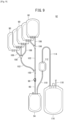
- the blood bag system 10 includes a plurality of bags (first to sixth bags 12, 14, 16, 18, 20, and 22) and a plurality of transfer tubes (first to sixth transfer tubes 24, 26, 28, 30, 32, and 34) .
- each of the first to sixth bags 12, 14, 16, 18, 20, and 22 is formed in a bag shape by stacking a sheet material having flexibility made of a soft resin such as polyvinyl chloride or polyolefin, and performing fusion bonding (thermal fusion bonding or high frequency fusion bonding) or adhesion in a seal portion at a periphery thereof.
- An initial flow blood bag 54 described below is similarly formed in a bag shape.
- the first bag 12 is a bag for accommodating (storing) blood (whole blood) collected from a donor.
- the first bag 12 may be referred to as a "blood collection bag 12".
- the blood collection bag 12 is used to store whole blood at the time of blood collection.
- the blood collection bag 12 is used to store and preserve the washed buffy coat obtained by adding the platelet added solution to the buffy coat corresponding to a remaining blood component. That is, the blood collection bag 12 serves as both a whole blood accommodation bag and a washed buffy coat accommodation bag.
- a blood preservation solution having a blood anticoagulant function is stored in the blood collection bag 12 in advance.
- the blood preservation solution include a blood preservation solution containing citric acid, phosphoric acid, glucose (citrate phosphate dextrose (CPD)), and the like.
- An amount of the blood preservation solution is set to an appropriate amount according to a scheduled blood collection amount.
- a blood collection tube 36 on a proximal end side is connected to a lower part of the blood collection bag 12.
- a clamp 38 for closing and opening a flow path of the blood collection tube 36 is provided in a midway portion of the blood collection tube 36.
- One end of a sealing member 40 is connected to the other end of the blood collection tube 36.
- the sealing member 40 may be configured such that a flow path is closed in initial state and opened by performing a breaking operation.
- a first port 42a of a branch connector 42 is connected to the other end of the sealing member 40.
- One end of the blood collection tube 44 on a distal end side is connected to a second port 42b of the branch connector 42, and a blood collection needle 46 is connected to the other end of the blood collection tube 44.
- a cap 48 is attached to the blood collection needle 46 before use.
- branch tube 50 One end of a branch tube 50 is connected to a third port 42c of the branch connector 42.
- a clamp 52 for closing and opening a flow path of the branch tube 50 is provided at a midway portion of the branch tube 50.
- the initial flow blood bag 54 is connected to the other end of the branch tube 50.
- a sampling port 56 is connected to the initial flow blood bag 54.
- a direction and arrangement of the branch connector 42 is not limited to the configuration illustrated in Fig. 1 , and may be appropriately changed.
- the second bag 14 is connected to the blood collection bag 12 through the first transfer tube 24 and is a bag for accommodating (storing) and preserving blood plasma corresponding to a light specific gravity blood component obtained by centrifugation.
- the second bag 14 may be referred to as a "blood plasma bag 14".
- the first transfer tube 24 is a tube for connecting an upper part of the blood collection bag 12 and an inlet of the blood plasma bag 14 and transferring the blood plasma from the blood collection bag 12 to the blood plasma bag 14.
- the third bag 16 is connected to the blood collection bag 12 through the second transfer tube 26 and is a bag for accommodating (storing) and preserving red cell concentrates corresponding to a heavy specific gravity blood component obtained by centrifugation.
- the third bag 16 may be referred to as a "first red blood cell bag 16".
- the second transfer tube 26 is a tube for connecting the lower part of the blood collection bag 12 and an inlet of the first red blood cell bag 16 and transferring the red cell concentrates from the blood collection bag 12 to the first red blood cell bag 16.
- the red cell concentrates stored and preserved in the first red blood cell bag 16 are red cell concentrates before removing a predetermined cell (white blood cell) (before filtration).
- an SAG-M (Saline Adenine Glucose Mannitol) liquid which is a mixed solution containing mannitol, glucose, adenine and sodium chloride is stored as a red blood cell preservation solution in the first red blood cell bag 16. Therefore, when the red cell concentrates obtained by centrifugation are transferred to the first red blood cell bag 16, a mixed liquid of the red cell concentrates before filtration and the red blood cell preservation solution (hereinafter referred to as "RC-SAGM”) is stored in the first red blood cell bag 16.
- RC-SAGM red blood cell preservation solution
- the fourth bag 18 is connected to the first bag 12 through the third transfer tube 28 and the second transfer tube 26, and is a bag for accommodating (storing) and preserving the platelet added solution.
- the fourth bag 18 may be referred to as an "added solution bag 18".
- the third transfer tube 28 is a tube for connecting an inlet of the added solution bag 18 and a midway portion of the second transfer tube 26 and transferring the platelet added solution to the blood collection bag 12 through the second transfer tube 26.
- the specific gravity of the platelet added solution is smaller than that of the buffy coat.
- the fifth bag 20 is connected to the blood collection bag 12 through the fourth transfer tube 30 and the first transfer tube 24 and is a bag for accommodating a waste liquid (a mixed liquid of the blood plasma and the platelet added solution) generated when the washed buffy coat is refined.
- the fifth bag 20 may be referred to as a "waste liquid bag 20".
- the fourth transfer tube 30 is a tube for connecting an inlet of the waste liquid bag 20 and a midway portion of the first transfer tube 24 and transferring the waste liquid in the blood collection bag 12 to the waste liquid bag 20 through the first transfer tube 24.
- the sixth bag 22 is connected to the third bag 16 through the fifth transfer tube 32, a filter 58 and the sixth transfer tube 34, and is a bag for accommodating (storing) and preserving the red cell concentrates from which the white blood cell is removed (specifically obtained by removing the white blood cell from the RC-SAGM) .
- the sixth bag 22 may be referred to as a "second red blood cell bag 22".
- the fifth transfer tube 32 is a tube for connecting the first red blood cell bag 16 and the filter 58 and transferring the red cell concentrates from the first red blood cell bag 16 to the filter 58.
- the filter 58 has a function of removing a predetermined cell, and, it is configured as a white blood cell removal filter in the present embodiment.
- the sixth transfer tube 34 is a tube for connecting the filter 58 and the second red blood cell bag 22 and transferring the red cell concentrates from which the white blood cell is removed from the filter 58 to the second red blood cell bag 22.
- a sampling tube 60 for taking out a part of the red cell concentrates is connected to the second red blood cell bag 22.
- Each tube in the blood bag system 10 is a transparent and flexible resin tube.
- the blood bag system 10 further includes a cassette 62.
- the cassette 62 is configured to hold the blood collection bag 12 and hold each part of the first to fourth transfer tubes 24, 26, 28, and 30.
- the blood bag system 10 includes first to fourth clamps 64, 66, 68, and 70 provided in the cassette 62.
- the first clamp 64 closes and opens a flow path of the first transfer tube 24 on a blood plasma bag 14 side of a connecting portion connected to the fourth transfer tube 30.
- the second clamp 66 closes and opens a flow path of the second transfer tube 26 on a first red blood cell bag 16 side of a connecting portion connected to the third transfer tube 28.
- the third clamp 68 closes and opens a flow path of the third transfer tube 28.
- the fourth clamp 70 closes and opens a flow path of the fourth transfer tube 30.
- Each of the first to fourth clamps 64, 66, 68, and 70 is configured to be opened and closed by clamp drive means (not illustrated).
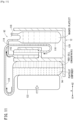
- the blood bag system 10 configured as described above is attached to a centrifugation transfer device 72 illustrated in Fig. 2 and used.
- the centrifugation transfer device 72 has a box shape, and includes a main device body 74, an openable lid 76 on an upper surface, a centrifugal drum 78 on an inside, six unit insertion holes 80 provided at equal angle intervals (60°) in the centrifugal drum 78, six insert units 82 inserted into the respective unit insertion holes 80, and six first pushers 84 and six second pushers 86 which are provided in a center portion and capable of advancing and retracting in a rotation radial direction with respect to the respective insert units 82 (see Fig. 3 ) .
- the centrifugation transfer device 72 operates based on an operation of an operation unit 88 provided on a front surface, and is controlled by a microcomputer (not illustrated).
- a direction of an arrow A of Fig. 3 corresponds to a radial direction of the centrifugal drum 78.
- a direction of an arrow A1 corresponds to a radially inward direction of the centrifugal drum 78
- a direction of an arrow A2 corresponds to a radially outward direction of the centrifugal drum 78 (a centrifugal force direction at the time of centrifugation).
- a plurality of chambers (not illustrated) is formed in the insert units 82 to hold the blood collection bag 12, the blood plasma bag 14, the first red blood cell bag 16, the added solution bag 18, the waste liquid bag 20, and the second red blood cell bag 22.
- the blood collection bag 12 is located in the direction of the arrow A2 from the added solution bag 18, and the blood plasma bag 14, the waste liquid bag 20 and the first red blood cell bag 16 are located in the direction of the arrow A2 from the blood collection bag 12.
- arrangement of the blood collection bag 12, the blood plasma bag 14, the first red blood cell bag 16, the added solution bag 18 and the waste liquid bag 20 with respect to the insert units 82 is not limited to an example of Fig. 3 and may be freely changed.
- first pusher 84 may be provided to be able to press the blood collection bag 12 in a rotation direction (circumferential direction) of the insert unit 82
- second pusher 86 may be provided to be able to press the added solution bag 18 in the rotation direction (circumferential direction) of the insert unit 82.
- a scheme of arranging and driving the first pusher 84 and the second pusher 86 is not limited as long as the pushers may press the bags.
- the blood bag system 10 is configured as described above.
- the blood treatment method (a method of refining the washed platelet) of the present embodiment will be described.
- a washed buffy coat refinement process primary centrifugation process
- a pooling process a pooling process
- a white blood cell removal process secondary centrifugation process
- a blood collection process, a mounting process, a centrifugation process, a first transfer process, a second transfer process and a third transfer process are performed in the washed buffy coat refinement process.
- an initial flow of blood (initial collected blood flow) from the donor is stored in the initial flow blood bag 54 by a predetermined amount.
- the sealing member 40 is in a closed state (initial state)
- the clamp 52 is brought into an open state.
- the initial collected blood flow may be introduced to the initial flow blood bag 54 through the blood collection tube 36, the branch connector 42, and the branch tube 50.
- a blood sampling tube (not illustrated) is attached to the sampling port, so that the initial collected blood flow is collected in the blood sampling tube .
- the collected initial collected blood flow is used as blood for examination.
- a part from the branch connector 42 to the sampling port may be omitted.
- the branch tube 50 is closed by the clamp 52, and the flow path of the blood collection tube 36 is opened by performing a breaking operation on the sealing member 40.
- the clamp 38 is in an open state.
- the blood from the donor flows into the blood collection bag 12 through the blood collection tube 36 in order.
- the blood collection bag 12 and the first to fourth transfer tubes 24, 26, 28, and 30 are held by the cassette 62, and the first to fourth clamps 64, 66, 68, and 70 are closed by the clamp drive means (not illustrated) to close the respective flow paths of the first to fourth transfer tubes 24, 26, 28, and 30.
- the blood collection tube 36 When a predetermined amount of blood is collected and stored in the blood collection bag 12, the blood collection tube 36 is closed by the clamp 38 so that the blood in the blood collection bag 12 does not flow out. Then, after the blood collection tube 36 is welded and sealed by a tube sealer and the like, the blood collection tube 36 is cut at a sealed portion.
- a portion of the whole blood bag system 10 illustrated in Fig. 1 on the blood collection bag 12 side of a cut portion of the blood collection tube 36 is also referred to as the "blood bag system 10".
- the blood bag system 10 is attached to the centrifugation transfer device 72 (see Fig. 2 ).
- the cassette 62 holding the blood collection bag 12 and the first to fourth transfer tubes 24, 26, 28, and 30 is attached to the insert unit 82.
- the blood collection bag 12 suspended and supported by the cassette 62 is in a state of being held in a chamber (not illustrated) of the insert unit 82.
- the blood plasma bag 14, the first red blood cell bag 16, the added solution bag 18, the waste liquid bag 20, the filter 58 and the second red blood cell bag 22 are held in a chamber (not illustrated) of the insert unit 82.
- the insert unit 82 held in the blood bag system 10 is inserted into the unit insertion hole 80 of the centrifugation transfer device 72.
- the six insert units 82 are attached to the centrifugation transfer device 72.
- five or fewer (preferably three or two at equal angle intervals) insert units 82 may be used when the insert units 82 are balanced.
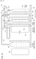
- FIG. 3 is a schematic view illustrating a state of the blood bag system 10 before performing the centrifugation process (before applying a centrifugal force) .
- the first to fourth clamps 64, 66, 68, and 70 are closed in advance, whereby the respective flow paths of the first to fourth transfer tubes 24, 26, 28, and 30 are closed.
- the centrifugation transfer device 72 rotates the centrifugal drum 78. Then, in response to the whole blood stored in the blood collection bag 12 receiving a centrifugal force, the red cell concentrates corresponding to a heavy specific gravityblood component move in the radially outward direction (the direction of the arrow A2), the blood plasma corresponding to a light specific gravity blood component moves in the radially inward direction (the direction of the arrow A1), and the buffy coat corresponding to a medium specific gravity blood component moves to an intermediate position therebetween, thereby separating the blood into three layers.
- the centrifugation transfer device 72 proceeds to the first transfer process.
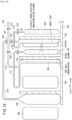
- the first transfer process while a centrifugal force is applied to the blood collection bag 12 by maintaining rotation of the centrifugal drum 78, the first clamp 64 and the second clamp 66 are opened by operating the clamp drive means (not illustrated). In this way, each of the flow paths of the first transfer tube 24 and the second transfer tube 26 is in an open state.
- the first pusher 84 is shifted in the centrifugal force direction, that is, in the radially outward direction (the direction of the arrow A2) to press the blood collection bag 12.
- the blood collection bag 12 is interposed between the first pusher 84 and a wall, and thus the volume thereof is reduced.
- the first transfer tube 24 is oriented toward an inner diameter side, blood plasma located on an innermost diameter side flows out from the blood collection bag 12 to the first transfer tube 24 and flows into the blood plasma bag 14 through the first transfer tube 24.
- the red cell concentrates located on an outermost diameter side flow out from the blood collection bag 12 to the second transfer tube 26 and flow into the first red blood cell bag 16 through the second transfer tube 26.
- the microcomputer detects that the blood plasma is transferred from the first transfer tube 24, and the first pusher 84 reaches a predetermined position, the flow path of the first transfer tube 24 is closed by closing the first clamp 64.
- the first pusher 84 is stopped in a step in which both the first clamp 64 and the second clamp 66 are closed.
- the buffy coat is stored in the blood collection bag 12 at the time when the first transfer process is completed.
- the centrifugation transfer device 72 proceeds to the second transfer process .
- the second transfer process while a centrifugal force is applied to the added solution bag 18 by maintaining rotation of the centrifugal drum 78, the third clamp 68 and the fourth clamp 70 are opened by operating the clamp drive means (not illustrated) . In this way, each of the flow paths of the third transfer tube 28 and the fourth transfer tube 30 is in an open state.
- the second pusher 86 is shifted in the centrifugal force direction, that is, in the radially outward direction (the direction of the arrow A2) to press the added solution bag 18.
- the added solution bag 18 is interposed between the second pusher 86 and a wall, and thus the volume thereof is reduced.
- the platelet added solution flows out from the added solution bag 18 to the third transfer tube 28 and flows into the blood collection bag 12 through the third transfer tube 28 and the second transfer tube 26.
- the second clamp 66 is closed, the platelet added solution is not mixed with the red cell concentrates stored in the first red blood cell bag 16.
- the specific gravity of the platelet added solution is smaller than that of the buffy coat, when the platelet added solution flows into an outer diameter side of the blood collection bag 12 from the second transfer tube 26, blood plasma in the buffy coat is pressed to an inner diameter side (in the direction of the arrow A1) by the platelet added solution to flow out from the blood collection bag 12 to the first transfer tube 24 and flow into the waste liquid bag 20 through the first transfer tube 24 and the fourth transfer tube 30.
- the platelet added solution is not mixed with the blood plasma stored in the blood plasma bag 14.
- the microcomputer detects that the platelet added solution is transferred from the added solution bag 18, and the second pusher 86 arrives at a predetermined position, the flow path of the third transfer tube 28 is closed by closing the third clamp 68, and the second pusher 86 is stopped.
- the fourth clamp 70 is kept in the open state.
- the centrifugation transfer device 72 proceeds to the third transfer process.
- the third transfer process while a centrifugal force is applied to the blood collection bag 12 by maintaining rotation of the centrifugal drum 78, the blood collection bag 12 is pressed by shifting the first pusher 84 in the centrifugal force direction as illustrated in Fig. 8 .
- the blood collection bag 12 is interposed between the first pusher 84 and a wall, and thus the volume thereof is reduced. In this way, an extra platelet added solution in the blood collection bag 12 flows into the waste liquid bag 20 from the blood collection bag 12 through the first transfer tube 24.
- the microcomputer detects that the first pusher 84 arrives at a predetermined position, the flow path of the fourth transfer tube 30 is closed by closing the fourth clamp 70, and the first pusher 84 is stopped.
- the blood bag system 10 is removed from the insert unit 82. Further, each bag is cut off by welding and sealing each of the first to fourth transfer tubes 24, 26, 28, and 30 in the blood bag system 10 using a tube sealer and the like, and then cutting each of the first to fourth transfer tubes 24, 26, 28, and 30. Thereafter, red cell concentrates temporarily stored in the first red blood cell bag 16 are passed through the filter 58 to remove a white blood cell. The red cell concentrates from which the white blood cell is removed are stored and preserved in the second red blood cell bag 22.
- the blood collection bag 12 (the first bag 12) accommodating the washed buffy coat obtained by the washed buffy coat refinement process may be referred to as a "cleaning BC bag 90".
- a platelet bag system 92 is configured by connecting a plurality of (five in Fig. 9 ) cleaning BC bags 90 to a tube.
- the platelet bag system 92 includes the plurality of cleaning BC bags 90 obtained in the washed buffy coat refinement process and a pooling bag 94 in which buffy coats in the cleaning BC bags 90 are collected.
- One end of an introduction tube 96 is connected to an upper portion of the pooling bag 94.
- the introduction tube 96 is provided with a clamp 98 that closes and opens a flow path of the introduction tube 96.
- One ends of two first branch tubes 102 are connected to the other end of the introduction tube 96 through a first branch connector 100.
- One ends of two second branch tubes 106 are connected to the other end of one first branch tube 102 through a second branch connector 104, and one ends of three second branch tubes 106 are connected to the other end of the other first branch tube 102 through a third branch connector 108.
- the cleaning BC bags 90 are connected to the other ends of the respective second branch tubes 106.
- first connection tube 110 is connected to the upper portion of the pooling bag 94.
- the other end of the first connection tube 110 is connected to a filter 112, and one end of a second connection tube 114 is connected to the filter 112.
- the other end of the second connection tube 114 is connected to a washed platelet bag 116.
- a sampling port 118 is connected to the washed platelet bag 116.
- Each bag of the platelet bag system 92 is configured similarly to the bag of the above-described blood bag system 10, and each tube of the platelet bag system 92 is configured similarly to the tube of the above-described blood bag system 10.
- the filter 112 is configured similarly to the filter 58 described above.
- the pooling bag 94 is disposed vertically below the plurality of cleaning BC bags 90 connected in parallel, and the clamp 98 is opened, thereby collecting the washed buffy coats in the respective cleaning BC bags 90 in the one pooling bag 94 through the second branch tubes 106, the first branch tubes 102, and the introduction tube 96 by action of gravity. Thereafter, the introduction tube 96 is welded and sealed by a sealer and the like, and then the introduction tube 96 is cut at a sealed portion.
- a portion of the whole platelet bag system 92 illustrated in Fig. 9 on the pooling bag 94 side of a cut portion of the introduction tube 96 is also referred to as the "platelet bag system 92".
- the pooling bag 94 of the platelet bag system 92 is attached to a cassette (not illustrated), and the cassette is attached to the insert unit 120 of the centrifugation transfer device 72.
- the filter 112 is located in the radially outward direction (the direction of the arrow A2) of the pooling bag 94
- the washed platelet bag 116 is located in the radially outward direction (the direction of the arrow A2) of the filter 112.
- the insert unit 120 is insertable into the unit insertion hole 80 (see Fig. 2 ) .
- the centrifugation transfer device 72 rotates the centrifugal drum 78. Then, as illustrated in Fig. 11 , the washed buffy coat stored in the pooling bag 94 receives a centrifugal force, so that the red cell concentrates move in the radially outward direction (the direction of the arrow A2), a platelet component moves in the radially inward direction (the direction of the arrow A1), and the red cell concentrates are separated into two layers.
- the pusher 122 is shifted in the centrifugal force direction, that is, the radially outward direction (the direction of the arrow A2) to press the pooling bag 94.
- the pooling bag 94 is interposed between the pusher 122 and a wall, and thus the volume thereof is reduced.
- the first connection tube 110 is oriented toward an inner diameter side, a platelet component located on an inner diameter side flows out from the pooling bag 94 to the first connection tube 110 and flows into the filter 112 through the first connection tube 110.
- a white blood cell is removed by passing the platelet component through the filter 112.
- the washed platelet corresponding to the platelet component from which the white blood cell is removed is stored and preserved in the washed platelet bag 116 through the second connection tube 114.
- the platelet added solution in the added solution bag 18 is transferred to an outer diameter side of the blood collection bag 12 on which a centrifugal force acts.
- the washed buffy coat washed medium specific gravity blood component
- waste liquid containing the blood plasma and the platelet added solution discharged from the blood collection bag 12 to the fourth transfer tube 30 is stored in the waste liquid bag 20, the waste liquid may be easily treated.
- the third transfer tube 28 connects the second transfer tube 26 and the added solution bag 18 to each other
- the fourth transfer tube 30 connects the first transfer tube 24 and the waste liquid bag 20 to each other. Therefore, it is possible to simplify configurations of the blood collection bag 12 and the tube.
- the waste liquid since the waste liquid is transferred from the blood collection bag 12 to the waste liquid bag 20 in a state in which the first clamp 64 is opened and the fourth clamp 70 is closed, the waste liquid does not flow into the blood plasma bag 14.
- the red cell concentrates are transferred from the blood collection bag 12 to the first red blood cell bag 16 in a state in which the second clamp 66 is opened and the third clamp 68 is closed, the red cell concentrates do not flow into the added solution bag 18.
- the platelet added solution is transferred from the added solution bag 18 to the blood collection bag 12 in a state in which the second clamp 66 is closed and the third clamp 68 is opened, the platelet added solution does not flow into the first red blood cell bag 16.
- the waste liquid is transferred from the blood collection bag 12 to the waste liquid bag 20 by closing the first clamp 64 and opening the fourth clamp 70, the waste liquid does not flow into the blood plasma bag 14.
- the platelet added solution may be transferred to the blood collection bag 12 by a centrifugal force.
- the platelet added solution may be more securely transferred to the blood collection bag 12.
- a residual amount of the blood plasma in the blood collection bag 12 may be further reduced.
- the platelet added solution is introduced to an outer diameter side of the blood collection bag 12 in the second transfer process, the blood plasma remaining in the blood collection bag 12 may be efficiently pushed out (discharged) from the blood collection bag 12 by the platelet added solution.
- the platelet added solution may be transferred to the blood collection bag 12 only by a centrifugal force without pressing the added solution bag 18 by the second pusher 86.
- a description will be given of a blood bag system 10A and a blood treatment method according to a second embodiment of the invention.
- the same reference symbol will be assigned to the same component as that in the blood bag system 10 according to the first embodiment described above, and a detailed description thereof will be omitted.
- the bloodbag system 10 A includes a plurality of bags (first to sixth bags 200, 202, 204, 206, 208, and 210) and a plurality of transfer tubes (first to sixth transfer tubes 212, 214, 216, 218, 220, and 222) .
- each of the first to sixth bags 200, 202, 204, 206, 208, and 210 is formed in a bag shape by stacking a sheet material having flexibility made of a soft resin such as polyvinyl chloride or polyolefin, and performing fusion bonding (thermal fusion bonding or high frequency fusion bonding) or adhesion in a seal portion at a periphery thereof.
- the first bag 200 is a bag for accommodating (storing) blood (whole blood) collected from the donor.
- the first bag 200 may be referred to as a "blood collection bag 200" .
- blood collection bag 200 As will be described below, after blood plasma obtained by centrifuging whole blood is transferred to the second bag 202, and a buffy coat is transferred to the third bag 204, red cell concentrates corresponding to remaining blood components are left in the blood collection bag 200.
- the same blood preservation solution as that in the above-described blood collection bag 200 is stored in the blood collection bag 200.
- One end of a blood collection tube 36 on a proximal end side is connected to an upper portion of the blood collection bag 200.
- the second bag 202 is connected to the blood collection bag 200 through the first transfer tube 212, and is a bag for accommodating (storing) and preserving blood plasma corresponding to a light specific gravity blood component obtained by centrifugation.
- the second bag 202 maybe referred to as a "blood plasma bag 202".
- the first transfer tube 212 is a tube for connecting the upper portion of the blood collection bag 200 to an inlet of the blood plasma bag 202 and transferring the blood plasma from the blood collection bag 200 to the blood plasma bag 202.
- the third bag 204 is connected to the blood collection bag 200 through the second transfer tube 214, and is a bag for accommodating (storing) and preserving a buffy coat corresponding to a medium specific gravity blood component obtained by centrifugation.
- the third bag 204 may be referred to as a "buffy coat bag 204".
- the second transfer tube 214 is a tube for connecting the upper portion of the blood collection bag 200 to an inlet of the buffy coat bag 204 and transferring the buffy coat from the blood collection bag 200 to the buffy coat bag 204.
- the fourth bag 206 is connected to the third bag 204 through the third transfer tube 216 and the second transfer tube 214, and is a bag for accommodating (storing) and preserving a platelet added solution.
- the fourth bag 206 may be referred to as an "added solution bag 206".
- the third transfer tube 216 is a tube for connecting an inlet of the added solution bag 206 and a midway portion of the second transfer tube 214 and transferring the platelet added solution to the buffy coat bag 204 through the second transfer tube 214.
- the fifth bag 208 is connected to the buffy coat bag 204 through the fourth transfer tube 218 and is a bag for accommodating a waste liquid (a mixed liquid of the blood plasma and the platelet added solution) generated when the washed buffy coat is refined.
- the fifth bag 208 may be referred to as a "waste liquid bag 208".
- the fourth transfer tube 218 is a tube for connecting an inlet of the waste liquid bag 208 and an upperportion of the buffy coat bag 204 and transferring the waste liquid in the buffy coat bag 204 to the waste liquid bag 208 through the fourth transfer tube 218.
- the sixth bag 210 is connected to the first bag 200 through the second transfer tube 214, the third transfer tube 216, the fifth transfer tube 220, a filter 58, and the sixth transfer tube 222, and is a bag for accommodating (storing) and preserving red cell concentrates from which a white blood cell is removed.
- the sixth bag 210 may be referred to as a "red blood cell bag 210".
- the fifth transfer tube 220 is a tube for connecting a midway portion of the third transfer tube 216 and the filter 58 and transferring the red cell concentrates from the blood collection bag 200 to the filter 58 through the second transfer tube 214 and the third transfer tube 216.
- the sixth transfer tube 222 is configured similarly to the above-described sixth transfer tube 34.
- the blood bag system 10A includes first to sixth clamps 224, 226, 228, 230, 232, and 234 provided in a cassette (not illustrated) .
- the first clamp 224 closes and opens a flow path of the first transfer tube 212.
- the second clamp 226 closes and opens a flow path of the second transfer tube 214 on a buffy coat bag 204 side of a connecting portion connected to the third transfer tube 216.
- the third clamp 228 closes and opens a flow path of the third transfer tube 216 on an added solution bag 206 side of a connecting portion connected to the fifth transfer tube 220.
- the fourth clamp 230 closes and opens the fourth transfer tube 218.
- the fifth clamp 232 closes and opens the fifth transfer tube 220.
- the sixth clamp 234 closes and opens a flow path of the second transfer tube 214 between the blood collection bag 200 and the buffy coat bag 204.
- Each of the first to sixth clamps 224, 226, 228, 230, 232, and 234 may be opened and closed by clamp drive means (not illustrated).
- the blood bag system 10A configured as described above is used by being attached to a centrifugation transfer device 240.
- the centrifugation transfer device 240 is configured similarly to the centrifugation transfer device 72 illustrated in Fig. 2 , and includes a lid 76, a centrifugal drum 78, a unit insertion hole 80, an operation unit 88, an insert unit 242, and first to third pushers 244, 246, and 248.
- a plurality of chambers (not illustrated) is formed in the insert unit 242 to hold the blood collection bag 200, the blood plasma bag 202, the buffy coat bag 204, the added solution bag 206, the waste liquid bag 208, and the red blood cell bag 210.
- the first pusher 244 presses the blood collection bag 200 in a rotation radial direction of the insert unit 242
- the second pusher 246 presses the added solution bag 206 in the rotation radial direction of the insert unit 242
- the third pusher 248 presses the buffy coat bag 204 in the rotation radial direction of the insert unit 242.
- the blood collection bag 200 in a state in which the insert unit 242 is inserted into the unit insertion hole 80, the blood collection bag 200 is located in a direction of an arrow A2 of the added solution bag 206, and the blood plasma bag 202, the buffy coat bag 204, and the waste liquid bag 208 are located in the direction of the arrow A2 of the blood collection bag 200.
- the first pusher 244 may be provided to be able to press the bloodcollectionbag200inarotationdirection (circumferential direction) of the insert unit 242
- the second pusher 246 may be provided to be able to press the added solution bag 206 in the rotation direction (circumferential direction) of the insert unit 242
- the third pusher 248 may be provided to be able to press the buffy coat bag 204 in the rotation direction (circumferential direction) of the insert unit 242.
- a scheme of arranging and driving the first to third pushers 244, 246, and 248 is not limited as long as the pushers may press the bags.
- a washed buffy coat refinement process primary centrifugation process
- a pooling process a white blood cell removal process
- secondary centrifugation process a washed buffy coat refinement process
- a blood collection process, a mounting process, a centrifugation process, a first transfer process, a second transfer process and a third transfer process are performed in the washed buffy coat refinement process. Since the blood collection process is similar to that of the first embodiment, a detailed description thereof will be omitted.
- the blood bag system 10A is attached to the centrifugation transfer device 240 (see Fig. 2 ).
- a cassette holding the blood collection bag 200 and the first to fifth transfer tubes 212, 214, 216, 218, and 220 is attached to the insert unit 242.
- the blood collection bag 200 suspended and supported by the cassette is in a state of being held in a chamber (not illustrated) of the insert unit 242.
- the blood plasma bag 202, the buffy coat bag 204, the added solution bag 206, the waste liquid bag 208, the filter 58, and the red blood cell bag 210 are held in a chamber (not illustrated) of the insert unit 242.
- Fig. 13 is a schematic view illustrating a state of the blood bag system 10A before the centrifugation process is performed (before a centrifugal force acts).
- the first to sixth clamps 224, 226, 228, 230, 232, and 234 are closed in advance, whereby the respective flow paths of the first through fifth transfer tubes 212, 214, 216, 218, and 220 are closed.
- the centrifugation transfer device 240 rotates the centrifugal drum 78. Then, in response to the whole blood stored in the blood collection bag 200 receiving a centrifugal force, the red cell concentrates corresponding to a heavy specific gravityblood component move in a radially outward direction (the direction of the arrow A2), the blood plasma corresponding to a light specific gravity blood component moves in a radially inward direction (the direction of the arrow A1), and the buffy coat corresponding to a medium specific gravity blood component moves to an intermediate position therebetween, thereby separating the blood into three layers.
- the centrifugation transfer device 240 proceeds to the first transfer process.
- the first transfer process while a centrifugal force is applied to the blood collection bag 200 by maintaining rotation of the centrifugal drum 78, the first clamp 224 is opened by operating the clamp drive means (not illustrated) . In this way, the flow path of the first transfer tube 212 is put in an open state.
- the first pusher 244 is shifted in the centrifugal force direction, that is, the radially outward direction (the direction of the arrow A2) to press the blood collection bag 200.
- the blood collection bag 200 is interposed between the first pusher 244 and a wall, and thus the volume thereof is reduced.
- the first transfer tube 212 is oriented toward an inner diameter side, blood plasma located on an innermost diameter side flows out from the blood collection bag 200 to the first transfer tube 212 and flows into the blood plasma bag 202 through the first transfer tube 212.
- the first clamp 224 is closed, and the second clamp 226 and the sixth clamp 234 are opened. In this way, the flow path of the first transfer tube 212 is closed, and the flow path of the second transfer tube 214 is put in an open state.
- the first pusher 244 is further shifted in the centrifugal direction to press the blood collection bag 200.
- the buffy coat flows out to the second transfer tube 214 from the blood collection bag 200 and flows into the buffy coat bag 204 through the second transfer tube 214.
- the sixth clamp 234 is closed.
- the blood plasma is stored in the blood plasma bag 202, the buffy coat is stored in the buffy coat bag 204, and the red cell concentrates are left in the blood collection bag 200.
- the centrifugation transfer device 240 proceeds to the second transfer process .
- the second transfer process while a centrifugal force is applied to the added solution bag 206 by maintaining rotation of the centrifugal drum 78, each of the third clamp 228 and the fourth clamp 230 is opened by operating the clamp drive means (not illustrated). In this way, each flow path of the third transfer tube 216 and the fourth transfer tube 218 is put in an open state.
- the second pusher 246 is shifted in the centrifugal force direction, that is, the radially outward direction (the direction of the arrow A2) to press the added solution bag 206.
- the added solution bag 206 is interposed between the second pusher 246 and a wall, and thus the volume thereof is reduced.
- the platelet added solution flows out from the added solution bag 206 to the third transfer tube 216 and flows into the buffy coat bag 204 through the third transfer tube 216 and the second transfer tube 214.
- the sixth clamp 234 is closed, the platelet added solution is not mixed with the red cell concentrates stored in the blood collection bag 200.
- the specific gravity of the platelet added solution is smaller than that of the buffy coat, when the platelet added solution flows into an outer diameter side of the buffy coat bag 204 from the second transfer tube 214, blood plasma in the buffy coat is pressed to an inner diameter side (in the direction of the arrow A1) by the platelet added solution to flow out from the buffy coat bag 204 to the fourth transfer tube 218 and flow into the waste liquid bag 208 through the fourth transfer tube 218.
- each of the second clamp 226 and the third clamp 228 is closed to close each flow path of the second transfer tube 214 and the third transfer tube 216, and the second pusher 246 is stopped.
- the fourth clamp 230 is kept open.
- the centrifugation transfer device 240 proceeds to the third transfer process.
- the third transfer process while a centrifugal force is applied to the buffy coat bag 204 by maintaining rotation of the centrifugal drum 78, the third pusher 248 is shifted in the centrifugal force direction to press the buffy coat bag 204 as illustrated in Fig. 18 .
- the buffy coat bag 204 is interposed between the third pusher 248 and a wall, and thus the volume thereof is reduced. In this way, an extra platelet added solution in the buffy coat bag 204 flows into the waste liquid bag 208 from the buffy coat bag 204 through the fourth transfer tube 218.
- the microcomputer detects that the third pusher 248 arrives at a predetermined position, the fourth clamp 230 is closed to close the flow path of the fourth transfer tube 218, and the third pusher 248 is stopped.
- the blood bag system 10A is removed from the insert unit 242. Further, each bag is cut off by welding and sealing each of the first to fourth transfer tubes 212, 214, 216, and 218 in the blood bag system 10A using a tube sealer and the like, and then cutting each of the first to fourth transfer tubes 212, 214, 216, and 218.
- the blood collection bag 200 and the filter 58 are connected by a tube. Then, thereafter, the red cell concentrates temporarily stored in the blood collection bag 200 are passed through the filter 58 to remove the white blood cell. The red cell concentrates from which the white blood cell is removed are stored and preserved in the red blood cell bag 210.
- the pooling process and the white blood cell removal process are the same as those of the first embodiment, and thus a detailed description thereof will be omitted.
- the same effect as that of the first embodiment described above may be obtained.
- the platelet added solution in the added solution bag 206 is transferred to an outer diameter side of the buffy coat bag 204 on which a centrifugal force acts.
- the washedbuffy coat maybe obtained. Therefore, it is possible to securely and efficiently obtain the washed buffy coat having a sufficiently low content rate of blood plasma in the buffy coat bag 204.
- the blood bag system and the blood treatment method according to the invention are not limited to the above-described embodiments, and various configurations may be adopted without departing from the subject matter of the invention.
Landscapes
- Health & Medical Sciences (AREA)
- Heart & Thoracic Surgery (AREA)
- Engineering & Computer Science (AREA)
- Life Sciences & Earth Sciences (AREA)
- General Health & Medical Sciences (AREA)
- Vascular Medicine (AREA)
- Hematology (AREA)
- Animal Behavior & Ethology (AREA)
- Veterinary Medicine (AREA)
- Public Health (AREA)
- Biomedical Technology (AREA)
- Anesthesiology (AREA)
- Thermal Sciences (AREA)
- Mechanical Engineering (AREA)
- Environmental Sciences (AREA)
- Physics & Mathematics (AREA)
- Dentistry (AREA)
- Zoology (AREA)
- Wood Science & Technology (AREA)
- Pathology (AREA)
- Cardiology (AREA)
- External Artificial Organs (AREA)
Description
- The present invention relates to a blood bag system according to claim 1, and a blood treatment method according to claim 3 for centrifuging whole blood or a blood component into a light specific gravity blood component, a medium specific gravity blood component, and a heavy specific gravity blood component. Document
EP 2 357 012 A1 shows a generic blood bag system. DocumentEP 2 982 393 A1 is considered closest prior art and shows a generic blood treatment method. - Recently, in transfusion, component transfusion has been performed to separate a component of blood (whole blood) obtained by blood donation and the like and provide only a component required by a patient. According to the component transfusion, a burden on a circulatory system or a side effect may be reduced for the patient, and effective use of the donated blood is attempted.
- In separation of a blood component, for example, a blood bag system including a plurality of bags and a plurality of tubes is attached to a centrifugation transfer device disclosed in document
WO 2014/162592 A . Further, the blood component is centrifuged into a supernatant PPP (platelet poor plasma) fraction corresponding to a light specific gravity blood component, a precipitated RCC (red cell concentrates) fraction corresponding to a heavy specific gravity blood component, and a buffy coat corresponding to a medium specific gravity blood component formed therebetween by the centrifugation transfer device. The respective centrifuged components are transferred to the plurality of bags and preserved. - Incidentally, at the time of transfusion of platelet preparation, there is a possibility that a patient may have a side effect of the transfusion. Blood plasma contained in the platelet preparation is considered as a cause of the side effect. For this reason, a platelet having a low blood plasma content rate (washed platelet: washed platelet concentrate) is desired at a transfusion site.
- When such a washed platelet is refined, first, the buffy coat is centrifuged from blood using the above-described centrifugation transfer device. Subsequently, buffy coat pooling is performed to transfer and gather buffy coats in the plurality of bags to one bag. Then, a platelet added solution is added to the buffy coats obtained by the buffy coat pooling to replace blood plasma remaining in the buffy coats with the platelet added solution. Thereafter, the buffy coats containing the platelet added solution (washed buffy coats) are centrifuged into a platelet component and a red blood cell, and a white blood cell is removed from the platelet component using a filter, thereby obtaining the washed platelet.
- However, a considerable amount of blood plasma (light specific gravity blood component) is contained in the buffy coat (medium specific gravity blood component) obtained by the above-described centrifugation. For this reason, in a method of replacing the blood plasma in the buffy coat with the platelet added solution, a washed platelet having a sufficiently low blood plasma content rate may not be efficiently obtained.
- The invention has been conceived in view of the above problems, and the object of the invention is to provide a blood bag system and a blood treatment method capable of securely and efficiently obtaining a medium specific gravity blood component having a sufficiently low content rate of a light specific gravity blood component.
- The object of the invention is achieved by a blood bag system according to claim 1 and a blood treatment method according to claim 3. Advantageous embodiments are carried out according to the dependent claims.
- A blood bag system according to the present invention includes: a first bag for storing whole blood or a blood component; a second bag and a third bag for storing two blood components, respectively, among a light specific gravity blood component, a medium specific gravity blood component, and a heavy specific gravity blood component obtained by centrifuging a content liquid in the first bag; a first transfer tube for connecting the first bag and the second bag to each other and transferring one blood component from the first bag to the second bag; and a second transfer tube for connecting the first bag and the third bag to each other and transferring the other blood component from the first bag to the third bag, wherein the blood bag system further includes: a fourth bag storing an added solution; and a third transfer tube for transferring the added solution from the fourth bag to a bag storing the medium specific gravity blood component, and a centrifugal force acts in a transfer completed state in which the two blood components are separately transferred to the second bag and the third bag, respectively, and the added solution is transferred from the fourth bag to the bag accommodating the medium specific gravity blood component through the third transfer tube, thereby discharging the light specific gravity blood component remaining in the medium specific gravity blood component to an outside of the bag.
- As mentioned in the introduction portion, a supernatant PPP (platelet poor plasma) fraction corresponds to the light specific gravity blood component, a precipitated RCC (red cell concentrates) fraction corresponds to the heavy specific gravity blood component, and a buffy coat corresponds to a medium specific gravity blood component formed therebetween.
- According to such a configuration, since the light specific gravity blood component remaining in the medium specific gravity blood component in the transfer completed state maybe discharged from the bag by the added solution, it is possible to obtain a washed medium specific gravity blood component. In this way, it is possible to securely and efficiently obtain a medium specific gravity blood component having a sufficiently low content rate of a light specific gravity blood component.
- According to the blood bag system, in the transfer completed state, the medium specific gravity blood component remains in the first bag, the light specific gravity blood component is stored in the second bag, and the heavy specific gravity blood component is stored in the third bag, and the third transfer tube is a tube for transferring the added solution from the fourth bag to the first bag.
- According to such a configuration, it is possible to efficiently store a medium specific gravity blood component having a sufficiently low content rate of a light specific gravity blood component in the first bag.
- The blood bag system also includes : a fifth bag that stores a waste liquid containing the light specific gravity blood component and the added solution discharged from the first bag; and a fourth transfer tube for transferring the waste liquid discharged from the first bag to the fifth bag.
- According to such a configuration, since the waste liquid discharged from the first bag is stored in the fifth bag, the waste liquid may be easily treated.
- According to the blood bag system, the third transfer tube connects the second transfer tube and the fourth bag to each other, and the fourth transfer tube connects the first transfer tube and the fifth bag to each other.
- According to such a configuration, configurations of the first bag and the tube may be simplified.
- The blood bag system may include: a first clamp that closes and opens a second bag side of a connecting portion connected to the fourth transfer tube in the first transfer tube; a second clamp that closes and opens a third bag side of a connecting portion connected to the third transfer tube in the second transfer tube; a third clamp that closes and opens the third transfer tube; and a fourth clamp that closes and opens the fourth transfer tube.
- According to such a configuration, when the first clamp is opened, and the fourth clamp is closed, the light specific gravity blood component obtained by centrifugation of the first bag may be smoothly transferred to the second bag without being allowed to flow into the fifth bag. In addition, when the second clamp is opened, and the third clamp is closed, the heavy specific gravity blood component obtained by centrifugation of the first bag may be smoothly transferred to the third bag without being allowed to flow into the fourth bag. Further, when the second clamp is closed, and the third clamp is opened, the added solution in the fourth bag may be smoothly transferred to the first bag without being allowed to flow into the third bag. Furthermore, when the first clamp is closed, and the fourth clamp is opened, the waste liquid discharged from the first bag may be transferred to the fifth bag without being allowed to flow into the second bag.
- According to the blood bag system, in the transfer completed state, the heavy specific gravity blood component remains in the first bag, the light specific gravity blood component is stored in the second bag, and the medium specific gravity blood component is stored in the third bag, and the third transfer tube is a tube for transferring the added solution from the fourth bag to the third bag.
- According to such a configuration, it is possible to efficiently store a medium specific gravity blood component having a sufficiently low content rate of a light specific gravity blood component in the third bag.
- According to such a configuration, since the waste liquid discharged from the third bag is stored in the fifth bag, the waste liquid may be easily treated.
- A blood treatment method according to the present invention includes: a centrifugation process of centrifuging whole blood or a blood component in a first bag into a light specific gravityblood component, a medium specific gravityblood component, and a heavy specific gravity blood component for each specific gravity; a first transfer process of transferring one of the light specific gravity blood component, the medium specific gravity blood component, and the heavy specific gravity blood component from the first bag to a second bag through a first transfer tube, and transferring the other one from the first bag to a third bag through a second transfer tube; and a second transfer process of transferring an added solution stored in a fourth bag to a bag accommodating the medium specific gravity blood component through a third transfer tube while a centrifugal force is applied to the bag after the first transfer process to discharge the light specific gravity blood component remaining in the medium specific gravity blood component from the bag, thereby obtaining a washed medium specific gravity blood component.
- According to such a method, since the light specific gravity blood component remaining in the medium specific gravity blood component in the second transfer process may be discharged from the bag by the added solution, it is possible to obtain a washed medium specific gravity blood component. In this way, it is possible to more securely and efficiently obtain a medium specific gravity blood component having a sufficiently low content rate of a light specific gravity blood component.
- According to the blood treatment method, in the first transfer process, the light specific gravity blood component is transferred to the second bag, and the heavy specific gravity blood component is transferred to the third bag, thereby leaving the medium specific gravity blood component in the first bag, and in the second transfer process, the added solution stored in the fourth bag is transferred to the first bag through the third transfer tube.
- According to such a method, it is possible to efficiently store a medium specific gravity blood component having a sufficiently low content rate of a light specific gravity blood component in the first bag.
- According to the blood treatment method, in the second transfer process, the first bag may be disposed in a centrifugal force direction from the fourth bag.
- According to such a method, it is possible to transfer the added solution in the fourth bag to the first bag using a centrifugal force.
- According to the blood treatment method, in the second transfer process, the added solution in the fourth bag may be transferred to the first bag through the third transfer tube by pressing the fourth bag.
- According to such a method, it is possible to more securely transfer the added solution in the fourth bag to the first bag.
- The blood treatment method also includes : a third transfer process of transferring a waste liquid containing the light specific gravity blood component and the added solution discharged from the first bag to a fifth bag through a fourth transfer tube after the second transfer process.
- According to such a method, since the waste liquid discharged from the first bag is stored in the fifth bag, the waste liquid may be easily treated.
- According to the blood treatment method, in the third transfer process, a part of the added solution in the first bag may be transferred to the fifth bag by pressing the first bag in a state in which the third transfer tube is closed.
- According to such a method, a residual amount of the blood plasma in the first bag may be further reduced.
- According to the blood treatment method, in the second transfer process, the added solution may be introduced to an outer diameter side of the first bag.
- According to such a method, the light specific gravity blood component remaining in the first bag may be efficiently discharged from the first bag by the added solution.
- The blood treatment method may include: a pooling process of collecting the washed medium specific gravity blood component in a plurality of bags in one pooling bag; and a white blood cell removal process of removing a white blood cell from the washed medium specific gravity blood component in the pooling bag.
- According to such a method, the white blood cell may be removed, and the washed medium specific gravity blood component may be obtained.
- According to the invention, since a light specific gravity blood component remaining in a medium specific gravity blood component may be discharged from a bag using an added solution, it is possible to securely and efficiently obtain a medium specific gravity blood component having a sufficiently low content rate of a light specific gravity blood component.
-
-
Fig. 1 is a schematic view illustrating an overall configuration of a blood bag system according to a first embodiment of the invention. -
Fig. 2 is a perspective view of a centrifugation transfer device. -
Fig. 3 is a schematic view illustrating a state of the blood bag system before a centrifugation process. -
Fig. 4 is a schematic view illustrating a state of the blood bag system after the centrifugation process and before a first transfer process. -
Fig. 5 is a schematic view illustrating a state of the blood bag system during the first transfer process. -
Fig. 6 is a schematic view illustrating a state of the blood bag system at the time when the first transfer process is completed. -
Fig. 7 is a schematic view illustrating a state of the blood bag system during a second transfer process. -
Fig. 8 is a schematic view illustrating a state of the blood bag system during a third transfer process. -
Fig. 9 is a schematic view for description of a pooling process. -
Fig. 10 is a schematic view illustrating a state before centrifugation of a washed buffy coat in a pooling bag attached to the centrifugation transfer device. -
Fig. 11 is a schematic view illustrating a state of transferring a washed platelet, which is obtained by removing a white blood cell from a platelet component obtained by centrifugation of the washed buffy coat, to a washed platelet bag. -
Fig. 12 is a schematic view illustrating an overall configuration of a blood bag system according to a second embodiment of the invention. -
Fig. 13 is a schematic view illustrating a state of the blood bag system before a centrifugation process according to the second embodiment. -
Fig. 14 is a schematic view illustrating a state of the blood bag system after the centrifugation process and before a first transfer process in a blood treatment method according to the second embodiment. -
Fig. 15 is a schematic view illustrating a state of the blood bag system that transfers blood plasma from a blood collection bag to a blood plasma bag in the first transfer process according to the second embodiment. -
Fig. 16 is a schematic view illustrating a state of the blood bag system that transfers a buffy coat from the blood collection bag to a buffy coat bag in the first transfer process according to the second embodiment. -
Fig. 17 is a schematic view of the blood bag system during a second transfer process according to the second embodiment. -
Fig. 18 is a schematic view of the blood bag system during a third transfer process according to the second embodiment. - Hereinafter, a blood bag system and a blood treatment method according to the invention will be described with reference to accompanying drawings using suitable embodiments.
- A
blood bag system 10 according to a first embodiment of the invention is intended to obtain a washed buffy coat used to refine a washed platelet (platelet preparation) having a sufficiently low blood plasma content rate. Specifically, theblood bag system 10 is intended to centrifuge blood (whole blood) containing a plurality of blood components into three blood components corresponding to blood plasma, a buffy coat, and red cell concentrates, and add a platelet added solution (also referred to as a platelet cleaning solution or a platelet preservation solution) to the buffy coat to refine the washed buffy coat. - As illustrated in
Fig. 1 , theblood bag system 10 includes a plurality of bags (first tosixth bags sixth transfer tubes sixth bags flow blood bag 54 described below is similarly formed in a bag shape. - The
first bag 12 is a bag for accommodating (storing) blood (whole blood) collected from a donor. Hereinafter, thefirst bag 12 may be referred to as a "blood collection bag 12". Theblood collection bag 12 is used to store whole blood at the time of blood collection. However, as described below, after blood plasma obtained by centrifuging the whole blood is transferred to thesecond bag 14, and the red cell concentrates are transferred to thethird bag 16, theblood collection bag 12 is used to store and preserve the washed buffy coat obtained by adding the platelet added solution to the buffy coat corresponding to a remaining blood component. That is, theblood collection bag 12 serves as both a whole blood accommodation bag and a washed buffy coat accommodation bag. - A blood preservation solution having a blood anticoagulant function is stored in the
blood collection bag 12 in advance. Examples of the blood preservation solution include a blood preservation solution containing citric acid, phosphoric acid, glucose (citrate phosphate dextrose (CPD)), and the like. An amount of the blood preservation solution is set to an appropriate amount according to a scheduled blood collection amount. - In addition, one end of a
blood collection tube 36 on a proximal end side is connected to a lower part of theblood collection bag 12. Aclamp 38 for closing and opening a flow path of theblood collection tube 36 is provided in a midway portion of theblood collection tube 36. One end of a sealingmember 40 is connected to the other end of theblood collection tube 36. The sealingmember 40 may be configured such that a flow path is closed in initial state and opened by performing a breaking operation. - A
first port 42a of abranch connector 42 is connected to the other end of the sealingmember 40. One end of theblood collection tube 44 on a distal end side is connected to asecond port 42b of thebranch connector 42, and ablood collection needle 46 is connected to the other end of theblood collection tube 44. Acap 48 is attached to theblood collection needle 46 before use. - One end of a
branch tube 50 is connected to athird port 42c of thebranch connector 42. Aclamp 52 for closing and opening a flow path of thebranch tube 50 is provided at a midway portion of thebranch tube 50. The initialflow blood bag 54 is connected to the other end of thebranch tube 50. Asampling port 56 is connected to the initialflow blood bag 54. A direction and arrangement of thebranch connector 42 is not limited to the configuration illustrated inFig. 1 , and may be appropriately changed. - The
second bag 14 is connected to theblood collection bag 12 through thefirst transfer tube 24 and is a bag for accommodating (storing) and preserving blood plasma corresponding to a light specific gravity blood component obtained by centrifugation. Hereinafter, thesecond bag 14 may be referred to as a "blood plasma bag 14". Thefirst transfer tube 24 is a tube for connecting an upper part of theblood collection bag 12 and an inlet of theblood plasma bag 14 and transferring the blood plasma from theblood collection bag 12 to theblood plasma bag 14. - The
third bag 16 is connected to theblood collection bag 12 through thesecond transfer tube 26 and is a bag for accommodating (storing) and preserving red cell concentrates corresponding to a heavy specific gravity blood component obtained by centrifugation. Hereinafter, thethird bag 16 may be referred to as a "first redblood cell bag 16". Thesecond transfer tube 26 is a tube for connecting the lower part of theblood collection bag 12 and an inlet of the first redblood cell bag 16 and transferring the red cell concentrates from theblood collection bag 12 to the first redblood cell bag 16. The red cell concentrates stored and preserved in the first redblood cell bag 16 are red cell concentrates before removing a predetermined cell (white blood cell) (before filtration). - For example, an SAG-M (Saline Adenine Glucose Mannitol) liquid which is a mixed solution containing mannitol, glucose, adenine and sodium chloride is stored as a red blood cell preservation solution in the first red
blood cell bag 16. Therefore, when the red cell concentrates obtained by centrifugation are transferred to the first redblood cell bag 16, a mixed liquid of the red cell concentrates before filtration and the red blood cell preservation solution (hereinafter referred to as "RC-SAGM") is stored in the first redblood cell bag 16. - The
fourth bag 18 is connected to thefirst bag 12 through thethird transfer tube 28 and thesecond transfer tube 26, and is a bag for accommodating (storing) and preserving the platelet added solution. Hereinafter, thefourth bag 18 may be referred to as an "addedsolution bag 18". Thethird transfer tube 28 is a tube for connecting an inlet of the addedsolution bag 18 and a midway portion of thesecond transfer tube 26 and transferring the platelet added solution to theblood collection bag 12 through thesecond transfer tube 26. The specific gravity of the platelet added solution is smaller than that of the buffy coat. - The
fifth bag 20 is connected to theblood collection bag 12 through thefourth transfer tube 30 and thefirst transfer tube 24 and is a bag for accommodating a waste liquid (a mixed liquid of the blood plasma and the platelet added solution) generated when the washed buffy coat is refined. Hereinafter, thefifth bag 20 may be referred to as a "waste liquid bag 20". Thefourth transfer tube 30 is a tube for connecting an inlet of thewaste liquid bag 20 and a midway portion of thefirst transfer tube 24 and transferring the waste liquid in theblood collection bag 12 to thewaste liquid bag 20 through thefirst transfer tube 24. - The
sixth bag 22 is connected to thethird bag 16 through thefifth transfer tube 32, afilter 58 and thesixth transfer tube 34, and is a bag for accommodating (storing) and preserving the red cell concentrates from which the white blood cell is removed (specifically obtained by removing the white blood cell from the RC-SAGM) . Hereinafter, thesixth bag 22 may be referred to as a "second redblood cell bag 22". - The
fifth transfer tube 32 is a tube for connecting the first redblood cell bag 16 and thefilter 58 and transferring the red cell concentrates from the first redblood cell bag 16 to thefilter 58. Thefilter 58 has a function of removing a predetermined cell, and, it is configured as a white blood cell removal filter in the present embodiment. - The
sixth transfer tube 34 is a tube for connecting thefilter 58 and the second redblood cell bag 22 and transferring the red cell concentrates from which the white blood cell is removed from thefilter 58 to the second redblood cell bag 22. Asampling tube 60 for taking out a part of the red cell concentrates is connected to the second redblood cell bag 22. - Each tube in the
blood bag system 10 is a transparent and flexible resin tube. - As illustrated in
Fig. 2 , theblood bag system 10 further includes acassette 62. Although not illustrated in detail in the present embodiment, thecassette 62 is configured to hold theblood collection bag 12 and hold each part of the first tofourth transfer tubes - As illustrated in
Figs. 1 and3 , theblood bag system 10 includes first tofourth clamps cassette 62. Thefirst clamp 64 closes and opens a flow path of thefirst transfer tube 24 on ablood plasma bag 14 side of a connecting portion connected to thefourth transfer tube 30. Thesecond clamp 66 closes and opens a flow path of thesecond transfer tube 26 on a first redblood cell bag 16 side of a connecting portion connected to thethird transfer tube 28. Thethird clamp 68 closes and opens a flow path of thethird transfer tube 28. Thefourth clamp 70 closes and opens a flow path of thefourth transfer tube 30. Each of the first tofourth clamps - For example, the
blood bag system 10 configured as described above is attached to acentrifugation transfer device 72 illustrated inFig. 2 and used. As illustrated inFig. 2 , thecentrifugation transfer device 72 has a box shape, and includes amain device body 74, anopenable lid 76 on an upper surface, acentrifugal drum 78 on an inside, six unit insertion holes 80 provided at equal angle intervals (60°) in thecentrifugal drum 78, sixinsert units 82 inserted into the respective unit insertion holes 80, and sixfirst pushers 84 and sixsecond pushers 86 which are provided in a center portion and capable of advancing and retracting in a rotation radial direction with respect to the respective insert units 82 (seeFig. 3 ) . Thecentrifugation transfer device 72 operates based on an operation of anoperation unit 88 provided on a front surface, and is controlled by a microcomputer (not illustrated). - In a state in which the
insert units 82 are inserted into the unit insertion holes 80, a direction of an arrow A ofFig. 3 corresponds to a radial direction of thecentrifugal drum 78. Inparticular, a direction of an arrow A1 corresponds to a radially inward direction of thecentrifugal drum 78, and a direction of an arrow A2 corresponds to a radially outward direction of the centrifugal drum 78 (a centrifugal force direction at the time of centrifugation). A plurality of chambers (not illustrated) is formed in theinsert units 82 to hold theblood collection bag 12, theblood plasma bag 14, the first redblood cell bag 16, the addedsolution bag 18, thewaste liquid bag 20, and the second redblood cell bag 22. - As illustrated in
Fig. 3 , in the present embodiment, in the state in which theinsert units 82 are inserted into the unit insertion holes 80, theblood collection bag 12 is located in the direction of the arrow A2 from the addedsolution bag 18, and theblood plasma bag 14, thewaste liquid bag 20 and the first redblood cell bag 16 are located in the direction of the arrow A2 from theblood collection bag 12. However, arrangement of theblood collection bag 12, theblood plasma bag 14, the first redblood cell bag 16, the addedsolution bag 18 and thewaste liquid bag 20 with respect to theinsert units 82 is not limited to an example ofFig. 3 and may be freely changed. Further, thefirst pusher 84 may be provided to be able to press theblood collection bag 12 in a rotation direction (circumferential direction) of theinsert unit 82, and thesecond pusher 86 may be provided to be able to press the addedsolution bag 18 in the rotation direction (circumferential direction) of theinsert unit 82. In other words, a scheme of arranging and driving thefirst pusher 84 and thesecond pusher 86 is not limited as long as the pushers may press the bags. - Basically, the
blood bag system 10 according to the present embodiment is configured as described above. Next, the blood treatment method (a method of refining the washed platelet) of the present embodiment will be described. In the present embodiment, a washed buffy coat refinement process (primary centrifugation process), a pooling process, and a white blood cell removal process (secondary centrifugation process) are successively performed. - A blood collection process, a mounting process, a centrifugation process, a first transfer process, a second transfer process and a third transfer process are performed in the washed buffy coat refinement process. In the blood collection process, prior to collection of blood into the
blood collection bag 12, an initial flow of blood (initial collected blood flow) from the donor is stored in the initialflow blood bag 54 by a predetermined amount. In this case, while the sealingmember 40 is in a closed state (initial state), theclamp 52 is brought into an open state. In this way, while inflow of the initial collected blood flow into theblood collection tube 36 side, that is, theblood collection bag 12 side is inhibited, the initial collected blood flow may be introduced to the initialflow blood bag 54 through theblood collection tube 36, thebranch connector 42, and thebranch tube 50. - Subsequently, a blood sampling tube (not illustrated) is attached to the sampling port, so that the initial collected blood flow is collected in the blood sampling tube . The collected initial collected blood flow is used as blood for examination. Depending on the use, a part from the
branch connector 42 to the sampling port may be omitted. - When collection of the initial collected blood flow is completed, the
branch tube 50 is closed by theclamp 52, and the flow path of theblood collection tube 36 is opened by performing a breaking operation on the sealingmember 40. In this instance, theclamp 38 is in an open state. Then, the blood from the donor flows into theblood collection bag 12 through theblood collection tube 36 in order. Before collection of blood in theblood collection bag 12 starts, it is preferable that theblood collection bag 12 and the first tofourth transfer tubes cassette 62, and the first tofourth clamps fourth transfer tubes - When a predetermined amount of blood is collected and stored in the
blood collection bag 12, theblood collection tube 36 is closed by theclamp 38 so that the blood in theblood collection bag 12 does not flow out. Then, after theblood collection tube 36 is welded and sealed by a tube sealer and the like, theblood collection tube 36 is cut at a sealed portion. In description of subsequent processes, a portion of the wholeblood bag system 10 illustrated inFig. 1 on theblood collection bag 12 side of a cut portion of theblood collection tube 36 is also referred to as the "blood bag system 10". - In the mounting process, the
blood bag system 10 is attached to the centrifugation transfer device 72 (seeFig. 2 ). In attachment of theblood bag system 10 to thecentrifugation transfer device 72, thecassette 62 holding theblood collection bag 12 and the first tofourth transfer tubes insert unit 82. In this way, theblood collection bag 12 suspended and supported by thecassette 62 is in a state of being held in a chamber (not illustrated) of theinsert unit 82. In addition, theblood plasma bag 14, the first redblood cell bag 16, the addedsolution bag 18, thewaste liquid bag 20, thefilter 58 and the second redblood cell bag 22 are held in a chamber (not illustrated) of theinsert unit 82. - Subsequently, the
insert unit 82 held in theblood bag system 10 is inserted into theunit insertion hole 80 of thecentrifugation transfer device 72. Basically, the sixinsert units 82 are attached to thecentrifugation transfer device 72. However, five or fewer (preferably three or two at equal angle intervals)insert units 82 may be used when theinsert units 82 are balanced. - Subsequently, after the
lid 76 of thecentrifugation transfer device 72 is closed, the centrifugation process, the first transfer process, the second transfer process, and the third transfer process are automatically performed by operating theoperation unit 88. Here,Fig. 3 is a schematic view illustrating a state of theblood bag system 10 before performing the centrifugation process (before applying a centrifugal force) . The first tofourth clamps fourth transfer tubes - As illustrated in
Fig. 4 , in the centrifugation process, thecentrifugation transfer device 72 rotates thecentrifugal drum 78. Then, in response to the whole blood stored in theblood collection bag 12 receiving a centrifugal force, the red cell concentrates corresponding to a heavy specific gravityblood component move in the radially outward direction (the direction of the arrow A2), the blood plasma corresponding to a light specific gravity blood component moves in the radially inward direction (the direction of the arrow A1), and the buffy coat corresponding to a medium specific gravity blood component moves to an intermediate position therebetween, thereby separating the blood into three layers. - Subsequently, the
centrifugation transfer device 72 proceeds to the first transfer process. In the first transfer process, while a centrifugal force is applied to theblood collection bag 12 by maintaining rotation of thecentrifugal drum 78, thefirst clamp 64 and thesecond clamp 66 are opened by operating the clamp drive means (not illustrated). In this way, each of the flow paths of thefirst transfer tube 24 and thesecond transfer tube 26 is in an open state. - Then, as illustrated in
Fig. 5 , thefirst pusher 84 is shifted in the centrifugal force direction, that is, in the radially outward direction (the direction of the arrow A2) to press theblood collection bag 12. Theblood collection bag 12 is interposed between thefirst pusher 84 and a wall, and thus the volume thereof is reduced. In this instance, since thefirst transfer tube 24 is oriented toward an inner diameter side, blood plasma located on an innermost diameter side flows out from theblood collection bag 12 to thefirst transfer tube 24 and flows into theblood plasma bag 14 through thefirst transfer tube 24. - Meanwhile, since the
second transfer tube 26 is connected to an outer diameter side of theblood collection bag 12, the red cell concentrates located on an outermost diameter side flow out from theblood collection bag 12 to thesecond transfer tube 26 and flow into the first redblood cell bag 16 through thesecond transfer tube 26. - When an optical sensor (not illustrated) detects that the red cell concentrates are transferred from the
second transfer tube 26, and a separation surface of the red cell concentrates and the buffy coat arrives at a predetermined position, the flow path of thesecond transfer tube 26 is closed by closing thesecond clamp 66. - In addition, when the microcomputer (not illustrated) detects that the blood plasma is transferred from the
first transfer tube 24, and thefirst pusher 84 reaches a predetermined position, the flow path of thefirst transfer tube 24 is closed by closing thefirst clamp 64. Thefirst pusher 84 is stopped in a step in which both thefirst clamp 64 and thesecond clamp 66 are closed. - As illustrated in
Fig. 6 , the buffy coat is stored in theblood collection bag 12 at the time when the first transfer process is completed. - Subsequently, the
centrifugation transfer device 72 proceeds to the second transfer process . In the second transfer process, while a centrifugal force is applied to the addedsolution bag 18 by maintaining rotation of thecentrifugal drum 78, thethird clamp 68 and thefourth clamp 70 are opened by operating the clamp drive means (not illustrated) . In this way, each of the flow paths of thethird transfer tube 28 and thefourth transfer tube 30 is in an open state. - Then, as illustrated in
Fig. 7 , thesecond pusher 86 is shifted in the centrifugal force direction, that is, in the radially outward direction (the direction of the arrow A2) to press the addedsolution bag 18. The addedsolution bag 18 is interposed between thesecond pusher 86 and a wall, and thus the volume thereof is reduced. In this way, the platelet added solution flows out from the addedsolution bag 18 to thethird transfer tube 28 and flows into theblood collection bag 12 through thethird transfer tube 28 and thesecond transfer tube 26. In this instance, since thesecond clamp 66 is closed, the platelet added solution is not mixed with the red cell concentrates stored in the first redblood cell bag 16. - In addition, since the specific gravity of the platelet added solution is smaller than that of the buffy coat, when the platelet added solution flows into an outer diameter side of the
blood collection bag 12 from thesecond transfer tube 26, blood plasma in the buffy coat is pressed to an inner diameter side (in the direction of the arrow A1) by the platelet added solution to flow out from theblood collection bag 12 to thefirst transfer tube 24 and flow into thewaste liquid bag 20 through thefirst transfer tube 24 and thefourth transfer tube 30. In this instance, since thefirst clamp 64 is closed, the platelet added solution is not mixed with the blood plasma stored in theblood plasma bag 14. - When the microcomputer (not illustrated) detects that the platelet added solution is transferred from the added
solution bag 18, and thesecond pusher 86 arrives at a predetermined position, the flow path of thethird transfer tube 28 is closed by closing thethird clamp 68, and thesecond pusher 86 is stopped. Thefourth clamp 70 is kept in the open state. - Thereafter, the
centrifugation transfer device 72 proceeds to the third transfer process. In the third transfer process, while a centrifugal force is applied to theblood collection bag 12 by maintaining rotation of thecentrifugal drum 78, theblood collection bag 12 is pressed by shifting thefirst pusher 84 in the centrifugal force direction as illustrated inFig. 8 . Theblood collection bag 12 is interposed between thefirst pusher 84 and a wall, and thus the volume thereof is reduced. In this way, an extra platelet added solution in theblood collection bag 12 flows into thewaste liquid bag 20 from theblood collection bag 12 through thefirst transfer tube 24. - When the microcomputer (not illustrated) detects that the
first pusher 84 arrives at a predetermined position, the flow path of thefourth transfer tube 30 is closed by closing thefourth clamp 70, and thefirst pusher 84 is stopped. - When the third transfer process is completed, the
blood bag system 10 is removed from theinsert unit 82. Further, each bag is cut off by welding and sealing each of the first tofourth transfer tubes blood bag system 10 using a tube sealer and the like, and then cutting each of the first tofourth transfer tubes blood cell bag 16 are passed through thefilter 58 to remove a white blood cell. The red cell concentrates from which the white blood cell is removed are stored and preserved in the second redblood cell bag 22. - In description below, the blood collection bag 12 (the first bag 12) accommodating the washed buffy coat obtained by the washed buffy coat refinement process may be referred to as a "cleaning
BC bag 90". - Subsequently, in the pooling process, first, a
platelet bag system 92 is configured by connecting a plurality of (five inFig. 9 ) cleaningBC bags 90 to a tube. As illustrated inFig. 9 , theplatelet bag system 92 includes the plurality of cleaningBC bags 90 obtained in the washed buffy coat refinement process and a poolingbag 94 in which buffy coats in the cleaningBC bags 90 are collected. - One end of an
introduction tube 96 is connected to an upper portion of the poolingbag 94. Theintroduction tube 96 is provided with aclamp 98 that closes and opens a flow path of theintroduction tube 96. One ends of twofirst branch tubes 102 are connected to the other end of theintroduction tube 96 through afirst branch connector 100. One ends of twosecond branch tubes 106 are connected to the other end of onefirst branch tube 102 through asecond branch connector 104, and one ends of threesecond branch tubes 106 are connected to the other end of the otherfirst branch tube 102 through athird branch connector 108. The cleaningBC bags 90 are connected to the other ends of the respectivesecond branch tubes 106. - In addition, one end of a
first connection tube 110 is connected to the upper portion of the poolingbag 94. The other end of thefirst connection tube 110 is connected to afilter 112, and one end of asecond connection tube 114 is connected to thefilter 112. The other end of thesecond connection tube 114 is connected to a washedplatelet bag 116. Asampling port 118 is connected to the washedplatelet bag 116. Each bag of theplatelet bag system 92 is configured similarly to the bag of the above-describedblood bag system 10, and each tube of theplatelet bag system 92 is configured similarly to the tube of the above-describedblood bag system 10. Thefilter 112 is configured similarly to thefilter 58 described above. - In the pooling process, the pooling
bag 94 is disposed vertically below the plurality of cleaningBC bags 90 connected in parallel, and theclamp 98 is opened, thereby collecting the washed buffy coats in the respective cleaning BCbags 90 in the onepooling bag 94 through thesecond branch tubes 106, thefirst branch tubes 102, and theintroduction tube 96 by action of gravity. Thereafter, theintroduction tube 96 is welded and sealed by a sealer and the like, and then theintroduction tube 96 is cut at a sealed portion. In description of subsequent processes, a portion of the wholeplatelet bag system 92 illustrated inFig. 9 on the poolingbag 94 side of a cut portion of theintroduction tube 96 is also referred to as the "platelet bag system 92". - Subsequently, in the white blood cell removal process, as illustrated in
Fig. 10 , the poolingbag 94 of theplatelet bag system 92 is attached to a cassette (not illustrated), and the cassette is attached to theinsert unit 120 of thecentrifugation transfer device 72. In this instance, thefilter 112 is located in the radially outward direction (the direction of the arrow A2) of the poolingbag 94, and the washedplatelet bag 116 is located in the radially outward direction (the direction of the arrow A2) of thefilter 112. Theinsert unit 120 is insertable into the unit insertion hole 80 (seeFig. 2 ) . - Thereafter, the
centrifugation transfer device 72 rotates thecentrifugal drum 78. Then, as illustrated inFig. 11 , the washed buffy coat stored in the poolingbag 94 receives a centrifugal force, so that the red cell concentrates move in the radially outward direction (the direction of the arrow A2), a platelet component moves in the radially inward direction (the direction of the arrow A1), and the red cell concentrates are separated into two layers. - Subsequently, while a centrifugal force is applied to the pooling
bag 94 by maintaining rotation of thecentrifugal drum 78, thepusher 122 is shifted in the centrifugal force direction, that is, the radially outward direction (the direction of the arrow A2) to press the poolingbag 94. The poolingbag 94 is interposed between thepusher 122 and a wall, and thus the volume thereof is reduced. In this instance, since thefirst connection tube 110 is oriented toward an inner diameter side, a platelet component located on an inner diameter side flows out from the poolingbag 94 to thefirst connection tube 110 and flows into thefilter 112 through thefirst connection tube 110. - Then, a white blood cell is removed by passing the platelet component through the
filter 112. The washed platelet corresponding to the platelet component from which the white blood cell is removed is stored and preserved in the washedplatelet bag 116 through thesecond connection tube 114. - According to the present embodiment, in a transfer completed state in which the blood plasma and the red cell concentrates obtained by centrifuging the whole blood (content liquid) in the
blood collection bag 12 are transferred to theblood plasma bag 14 and the first redblood cell bag 16, respectively, the platelet added solution in the addedsolution bag 18 is transferred to an outer diameter side of theblood collection bag 12 on which a centrifugal force acts. In this way, since the blood plasma remaining in the buffy coat may be pushed out (discharged) from theblood collection bag 12 by the platelet added solution, the washed buffy coat (washed medium specific gravity blood component) may be obtained. Therefore, it is possible to securely and efficiently obtain the washed buffy coat having a sufficiently low content rate of blood plasma in theblood collection bag 12. Since the washed platelet is refined using such a washed buffy coat, it is possible to securely and efficiently obtain the washed platelet having a sufficiently low blood plasma content rate. - In addition, since the waste liquid containing the blood plasma and the platelet added solution discharged from the
blood collection bag 12 to thefourth transfer tube 30 is stored in thewaste liquid bag 20, the waste liquid may be easily treated. - Further, the
third transfer tube 28 connects thesecond transfer tube 26 and the addedsolution bag 18 to each other, and thefourth transfer tube 30 connects thefirst transfer tube 24 and thewaste liquid bag 20 to each other. Therefore, it is possible to simplify configurations of theblood collection bag 12 and the tube. - In the present embodiment, since the waste liquid is transferred from the
blood collection bag 12 to thewaste liquid bag 20 in a state in which thefirst clamp 64 is opened and thefourth clamp 70 is closed, the waste liquid does not flow into theblood plasma bag 14. - In addition, since the red cell concentrates are transferred from the
blood collection bag 12 to the first redblood cell bag 16 in a state in which thesecond clamp 66 is opened and thethird clamp 68 is closed, the red cell concentrates do not flow into the addedsolution bag 18. - Further, since the platelet added solution is transferred from the added
solution bag 18 to theblood collection bag 12 in a state in which thesecond clamp 66 is closed and thethird clamp 68 is opened, the platelet added solution does not flow into the first redblood cell bag 16. - Furthermore, since the waste liquid is transferred from the
blood collection bag 12 to thewaste liquid bag 20 by closing thefirst clamp 64 and opening thefourth clamp 70, the waste liquid does not flow into theblood plasma bag 14. - According to the present embodiment, since the
blood collection bag 12 is disposed in a centrifugal direction from the addedsolution bag 18 in the second transfer process, the platelet added solution may be transferred to theblood collection bag 12 by a centrifugal force. - In addition, since the added
solution bag 18 is pressed by thesecond pusher 86 in the second transfer process, the platelet added solution may be more securely transferred to theblood collection bag 12. - Further, since a part of the platelet added solution in the
blood collection bag 12 is transferred to thewaste liquid bag 20 in a state in which thethird transfer tube 28 is closed by thethird clamp 68 in the third transfer process, a residual amount of the blood plasma in the blood collection bag 12 (the cleaning BC bag 90) may be further reduced. - Furthermore, since the platelet added solution is introduced to an outer diameter side of the
blood collection bag 12 in the second transfer process, the blood plasma remaining in theblood collection bag 12 may be efficiently pushed out (discharged) from theblood collection bag 12 by the platelet added solution. - The present embodiment is not limited to the above-described configuration and method. For example, in the second transfer process, the platelet added solution may be transferred to the
blood collection bag 12 only by a centrifugal force without pressing the addedsolution bag 18 by thesecond pusher 86. - Next, a description will be given of a
blood bag system 10A and a blood treatment method according to a second embodiment of the invention. In theblood bag system 10A according to the present embodiment, the same reference symbol will be assigned to the same component as that in theblood bag system 10 according to the first embodiment described above, and a detailed description thereof will be omitted. - As illustrated in
Fig. 12 , thebloodbag system 10 A includes a plurality of bags (first tosixth bags sixth transfer tubes sixth bags - The
first bag 200 is a bag for accommodating (storing) blood (whole blood) collected from the donor. Hereinafter, thefirst bag 200 may be referred to as a "blood collection bag 200" . As will be described below, after blood plasma obtained by centrifuging whole blood is transferred to thesecond bag 202, and a buffy coat is transferred to thethird bag 204, red cell concentrates corresponding to remaining blood components are left in theblood collection bag 200. The same blood preservation solution as that in the above-describedblood collection bag 200 is stored in theblood collection bag 200. One end of ablood collection tube 36 on a proximal end side is connected to an upper portion of theblood collection bag 200. - The
second bag 202 is connected to theblood collection bag 200 through thefirst transfer tube 212, and is a bag for accommodating (storing) and preserving blood plasma corresponding to a light specific gravity blood component obtained by centrifugation. Hereinafter, thesecond bag 202 maybe referred to as a "blood plasma bag 202". Thefirst transfer tube 212 is a tube for connecting the upper portion of theblood collection bag 200 to an inlet of theblood plasma bag 202 and transferring the blood plasma from theblood collection bag 200 to theblood plasma bag 202. - The
third bag 204 is connected to theblood collection bag 200 through thesecond transfer tube 214, and is a bag for accommodating (storing) and preserving a buffy coat corresponding to a medium specific gravity blood component obtained by centrifugation. Hereinafter, thethird bag 204 may be referred to as a "buffy coat bag 204". Thesecond transfer tube 214 is a tube for connecting the upper portion of theblood collection bag 200 to an inlet of thebuffy coat bag 204 and transferring the buffy coat from theblood collection bag 200 to thebuffy coat bag 204. - The
fourth bag 206 is connected to thethird bag 204 through thethird transfer tube 216 and thesecond transfer tube 214, and is a bag for accommodating (storing) and preserving a platelet added solution. Hereinafter, thefourth bag 206 may be referred to as an "addedsolution bag 206". Thethird transfer tube 216 is a tube for connecting an inlet of the addedsolution bag 206 and a midway portion of thesecond transfer tube 214 and transferring the platelet added solution to thebuffy coat bag 204 through thesecond transfer tube 214. - The
fifth bag 208 is connected to thebuffy coat bag 204 through thefourth transfer tube 218 and is a bag for accommodating a waste liquid (a mixed liquid of the blood plasma and the platelet added solution) generated when the washed buffy coat is refined. Hereinafter, thefifth bag 208 may be referred to as a "waste liquid bag 208". Thefourth transfer tube 218 is a tube for connecting an inlet of thewaste liquid bag 208 and an upperportion of thebuffy coat bag 204 and transferring the waste liquid in thebuffy coat bag 204 to thewaste liquid bag 208 through thefourth transfer tube 218. - The
sixth bag 210 is connected to thefirst bag 200 through thesecond transfer tube 214, thethird transfer tube 216, thefifth transfer tube 220, afilter 58, and thesixth transfer tube 222, and is a bag for accommodating (storing) and preserving red cell concentrates from which a white blood cell is removed. Hereinafter, thesixth bag 210 may be referred to as a "redblood cell bag 210". - The
fifth transfer tube 220 is a tube for connecting a midway portion of thethird transfer tube 216 and thefilter 58 and transferring the red cell concentrates from theblood collection bag 200 to thefilter 58 through thesecond transfer tube 214 and thethird transfer tube 216. Thesixth transfer tube 222 is configured similarly to the above-describedsixth transfer tube 34. - As illustrated in
Figs. 12 and13 , theblood bag system 10A includes first tosixth clamps first clamp 224 closes and opens a flow path of thefirst transfer tube 212. Thesecond clamp 226 closes and opens a flow path of thesecond transfer tube 214 on abuffy coat bag 204 side of a connecting portion connected to thethird transfer tube 216. Thethird clamp 228 closes and opens a flow path of thethird transfer tube 216 on an addedsolution bag 206 side of a connecting portion connected to thefifth transfer tube 220. Thefourth clamp 230 closes and opens thefourth transfer tube 218. Thefifth clamp 232 closes and opens thefifth transfer tube 220. Thesixth clamp 234 closes and opens a flow path of thesecond transfer tube 214 between theblood collection bag 200 and thebuffy coat bag 204. Each of the first tosixth clamps - For example, the
blood bag system 10A configured as described above is used by being attached to acentrifugation transfer device 240. Thecentrifugation transfer device 240 is configured similarly to thecentrifugation transfer device 72 illustrated inFig. 2 , and includes alid 76, acentrifugal drum 78, aunit insertion hole 80, anoperation unit 88, aninsert unit 242, and first tothird pushers insert unit 242 to hold theblood collection bag 200, theblood plasma bag 202, thebuffy coat bag 204, the addedsolution bag 206, thewaste liquid bag 208, and the redblood cell bag 210. - The
first pusher 244 presses theblood collection bag 200 in a rotation radial direction of theinsert unit 242, thesecond pusher 246 presses the addedsolution bag 206 in the rotation radial direction of theinsert unit 242, and thethird pusher 248 presses thebuffy coat bag 204 in the rotation radial direction of theinsert unit 242. - As illustrated in
Fig. 13 , in the present embodiment, in a state in which theinsert unit 242 is inserted into theunit insertion hole 80, theblood collection bag 200 is located in a direction of an arrow A2 of the addedsolution bag 206, and theblood plasma bag 202, thebuffy coat bag 204, and thewaste liquid bag 208 are located in the direction of the arrow A2 of theblood collection bag 200. - However, arrangement of the
blood collection bag 200, theblood plasma bag 202, thebuffy coat bag 204, and thewaste liquid bag 208 with respect to theinsert unit 242 is not limited to an example ofFig. 13 , and may be freely changed. In addition, thefirst pusher 244 may be provided to be able to press the bloodcollectionbag200inarotationdirection (circumferential direction) of theinsert unit 242, thesecond pusher 246 may be provided to be able to press the addedsolution bag 206 in the rotation direction (circumferential direction) of theinsert unit 242, and thethird pusher 248 may be provided to be able to press thebuffy coat bag 204 in the rotation direction (circumferential direction) of theinsert unit 242. In other words, a scheme of arranging and driving the first tothird pushers - Next, a description will be given of the blood treatment method (a method of refining the washed platelet) of the present embodiment. In the present embodiment, a washed buffy coat refinement process (primary centrifugation process), a pooling process, and a white blood cell removal process (secondary centrifugation process) are successively performed.
- A blood collection process, a mounting process, a centrifugation process, a first transfer process, a second transfer process and a third transfer process are performed in the washed buffy coat refinement process. Since the blood collection process is similar to that of the first embodiment, a detailed description thereof will be omitted.
- In the mounting process, the
blood bag system 10A is attached to the centrifugation transfer device 240 (seeFig. 2 ). In attachment of theblood bag system 10A to thecentrifugation transfer device 240, a cassette holding theblood collection bag 200 and the first tofifth transfer tubes insert unit 242. In this way, theblood collection bag 200 suspended and supported by the cassette is in a state of being held in a chamber (not illustrated) of theinsert unit 242. In addition, theblood plasma bag 202, thebuffy coat bag 204, the addedsolution bag 206, thewaste liquid bag 208, thefilter 58, and the redblood cell bag 210 are held in a chamber (not illustrated) of theinsert unit 242. - Subsequently, the centrifugation process, the first transfer process, the second transfer process, and the third transfer process are automatically performed by operating the
operation unit 88 after theinsert unit 242 in which theblood bag system 10A is held is inserted into theunit insertion hole 80 of thecentrifugation transfer device 240, and thelid 76 of thecentrifugation transfer device 240 is closed. Here,Fig. 13 is a schematic view illustrating a state of theblood bag system 10A before the centrifugation process is performed (before a centrifugal force acts). The first tosixth clamps fifth transfer tubes - As illustrated in
Fig. 14 , in the centrifugation process, thecentrifugation transfer device 240 rotates thecentrifugal drum 78. Then, in response to the whole blood stored in theblood collection bag 200 receiving a centrifugal force, the red cell concentrates corresponding to a heavy specific gravityblood component move in a radially outward direction (the direction of the arrow A2), the blood plasma corresponding to a light specific gravity blood component moves in a radially inward direction (the direction of the arrow A1), and the buffy coat corresponding to a medium specific gravity blood component moves to an intermediate position therebetween, thereby separating the blood into three layers. - Subsequently, the
centrifugation transfer device 240 proceeds to the first transfer process. In the first transfer process, while a centrifugal force is applied to theblood collection bag 200 by maintaining rotation of thecentrifugal drum 78, thefirst clamp 224 is opened by operating the clamp drive means (not illustrated) . In this way, the flow path of thefirst transfer tube 212 is put in an open state. - Then, as illustrated in
Fig. 15 , thefirst pusher 244 is shifted in the centrifugal force direction, that is, the radially outward direction (the direction of the arrow A2) to press theblood collection bag 200. Theblood collection bag 200 is interposed between thefirst pusher 244 and a wall, and thus the volume thereof is reduced. In this instance, since thefirst transfer tube 212 is oriented toward an inner diameter side, blood plasma located on an innermost diameter side flows out from theblood collection bag 200 to thefirst transfer tube 212 and flows into theblood plasma bag 202 through thefirst transfer tube 212. - After transfer of the blood plasma from the
first transfer tube 212 to theblood plasma bag 202 is completed, thefirst clamp 224 is closed, and thesecond clamp 226 and thesixth clamp 234 are opened. In this way, the flow path of thefirst transfer tube 212 is closed, and the flow path of thesecond transfer tube 214 is put in an open state. - Subsequently, as illustrated in
Fig. 16 , thefirst pusher 244 is further shifted in the centrifugal direction to press theblood collection bag 200. In this instance, since thesecond transfer tube 214 is connected to an inner diameter side of a separation surface of the red cell concentrates and the buffy coat in theblood collection bag 200, the buffy coat flows out to thesecond transfer tube 214 from theblood collection bag 200 and flows into thebuffy coat bag 204 through thesecond transfer tube 214. After transfer of the buffy coat from thesecond transfer tube 214 to thebuffy coat bag 204 is completed, thesixth clamp 234 is closed. - At the time when the first transfer process is completed, the blood plasma is stored in the
blood plasma bag 202, the buffy coat is stored in thebuffy coat bag 204, and the red cell concentrates are left in theblood collection bag 200. - Subsequently, the
centrifugation transfer device 240 proceeds to the second transfer process . In the second transfer process, while a centrifugal force is applied to the addedsolution bag 206 by maintaining rotation of thecentrifugal drum 78, each of thethird clamp 228 and thefourth clamp 230 is opened by operating the clamp drive means (not illustrated). In this way, each flow path of thethird transfer tube 216 and thefourth transfer tube 218 is put in an open state. - Then, as illustrated in
Fig. 17 , thesecond pusher 246 is shifted in the centrifugal force direction, that is, the radially outward direction (the direction of the arrow A2) to press the addedsolution bag 206. The addedsolution bag 206 is interposed between thesecond pusher 246 and a wall, and thus the volume thereof is reduced. In this way, the platelet added solution flows out from the addedsolution bag 206 to thethird transfer tube 216 and flows into thebuffy coat bag 204 through thethird transfer tube 216 and thesecond transfer tube 214. In this instance, since thesixth clamp 234 is closed, the platelet added solution is not mixed with the red cell concentrates stored in theblood collection bag 200. - In addition, since the specific gravity of the platelet added solution is smaller than that of the buffy coat, when the platelet added solution flows into an outer diameter side of the
buffy coat bag 204 from thesecond transfer tube 214, blood plasma in the buffy coat is pressed to an inner diameter side (in the direction of the arrow A1) by the platelet added solution to flow out from thebuffy coat bag 204 to thefourth transfer tube 218 and flow into thewaste liquid bag 208 through thefourth transfer tube 218. - When a microcomputer (not illustrated) detects that the platelet added solution is transferred from the added
solution bag 206 and thesecond pusher 246 arrives at a predetermined position, each of thesecond clamp 226 and thethird clamp 228 is closed to close each flow path of thesecond transfer tube 214 and thethird transfer tube 216, and thesecond pusher 246 is stopped. Thefourth clamp 230 is kept open. - Thereafter, the
centrifugation transfer device 240 proceeds to the third transfer process. In the third transfer process, while a centrifugal force is applied to thebuffy coat bag 204 by maintaining rotation of thecentrifugal drum 78, thethird pusher 248 is shifted in the centrifugal force direction to press thebuffy coat bag 204 as illustrated inFig. 18 . Thebuffy coat bag 204 is interposed between thethird pusher 248 and a wall, and thus the volume thereof is reduced. In this way, an extra platelet added solution in thebuffy coat bag 204 flows into thewaste liquid bag 208 from thebuffy coat bag 204 through thefourth transfer tube 218. - When the microcomputer (not illustrated) detects that the
third pusher 248 arrives at a predetermined position, thefourth clamp 230 is closed to close the flow path of thefourth transfer tube 218, and thethird pusher 248 is stopped. - When the third transfer process is completed, the
blood bag system 10A is removed from theinsert unit 242. Further, each bag is cut off by welding and sealing each of the first tofourth transfer tubes blood bag system 10A using a tube sealer and the like, and then cutting each of the first tofourth transfer tubes blood collection bag 200 and thefilter 58 are connected by a tube. Then, thereafter, the red cell concentrates temporarily stored in theblood collection bag 200 are passed through thefilter 58 to remove the white blood cell. The red cell concentrates from which the white blood cell is removed are stored and preserved in the redblood cell bag 210. - The pooling process and the white blood cell removal process are the same as those of the first embodiment, and thus a detailed description thereof will be omitted.
- According to the present embodiment, the same effect as that of the first embodiment described above may be obtained. In more detail, in a transfer completed state in which the blood plasma and the buffy coat obtained by centrifuging the whole blood (content liquid) in the
blood collection bag 200 are transferred to theblood plasma bag 202 and thebuffy coat bag 204, respectively, the platelet added solution in the addedsolution bag 206 is transferred to an outer diameter side of thebuffy coat bag 204 on which a centrifugal force acts. In this way, since the blood plasma remaining in the buffy coat may be discharged from thebuffy coat bag 204 by the platelet addedsolution, the washedbuffy coat maybe obtained. Therefore, it is possible to securely and efficiently obtain the washed buffy coat having a sufficiently low content rate of blood plasma in thebuffy coat bag 204. - The blood bag system and the blood treatment method according to the invention are not limited to the above-described embodiments, and various configurations may be adopted without departing from the subject matter of the invention.
-
- 10, 10A blood bag system
- 12, 200 blood collection bag (first bag)
- 14, 202 blood plasma bag (second bag)
- 16 first red blood cell bag (third bag)
- 18, 206 added solution bag (fourth bag)
- 20, 208 waste liquid bag (fifth bag)
- 22 second red blood cell bag (sixth bag)
- 24, 212 first transfer tube
- 26, 214 second transfer tube
- 28, 216 third transfer tube
- 30, 218 fourth transfer tube
- 32, 220 fifth transfer tube
- 34, 222 sixth transfer tube
- 64, 224 first clamp
- 66, 226 second clamp
- 68, 228 third clamp
- 70, 230 fourth clamp
- 72, 240 centrifugation transfer device
- 204 buffy coat bag (third bag)
- 210 red blood cell bag (sixth bag)
Claims (8)
- A blood bag system (10) comprising:a first bag (12) configured to store whole blood or a blood component, and having an upper part and a lower part;a second bag (14) and a third bag (16) configured to store two blood components, respectively, among a plasma, a buffy coat, and red blood cells obtained by centrifuging a content liquid in the first bag (12);a first transfer tube (24) connecting an upper part of the first bag (12) and the second bag (14) to each other and configured to transfer one blood component from the first bag (12) to the second bag (14); anda second transfer tube (26) connecting a lower part of the first bag (12) and the third bag (16) to each other and configured to transfer the other blood component from the first bag (12) to the third bag (16), whereinthe blood bag system (10) further comprises:a fourth bag (18) storing a platelet added solution; anda third transfer tube (28) connecting an inlet of the fourth bag (18) and a midway portion of the second transfer tube (26), and configured to transfer the platelet added solution from the fourth bag (18) to the first bag (12) storing the buffy coat, anda fifth bag (20) configured to store a waste liquid containing the plasma remaining in the buffy coat and the platelet added solution discharged from the first bag (12); andthe fifth bag (20) being connected with the first bag (12) by means of a fourth transfer tube (30) connecting an inlet of the fifth bag (20) and a midway portion of the first transfer tube (24), the fourth transfer tube (30) configured to transfer the waste liquid discharged from the first bag (12) to the fifth bag (20),the blood bag system (10) being configured to, upon receiving of a centrifugal force acting in a transfer completed state in which the two blood components have been separately transferred to the second bag (14) and the third bag (16), respectively, have the platelet added solution transferred from the fourth bag (18) to the first bag (12) storing the buffy coat through the third transfer tube (28), and to thereby discharge the plasma remaining in the buffy coat to the fifth bag (20), such thatin the transfer completed state, the buffy coat remains in the first bag (12), the plasma is stored in the second bag (14), and the red blood cells are stored in the third bag (16).
- The blood bag system (10) according to claim 1, comprising:a first clamp (64) that is configured to close and open a second bag side of a connecting portion connected to the fourth transfer tube (30) in the first transfer tube (24);a second clamp (66) that is configured to close and open a third bag side of a connecting portion connected to the third transfer tube (28) in the second transfer tube (26);a third clamp (68) that is configured to close and open the third transfer tube (28); anda fourth clamp (70) that is configured to close and open the fourth transfer tube (30).
- A blood treatment method comprising:a centrifugation process of centrifuging whole blood or a blood component in a first bag (12) into a plasma, a buffy coat, and a red blood cells for each specific gravity;a first transfer process of transferring one of the plasma, the buffy coat, and the red blood cells from the first bag (12) to a second bag (14) through a first transfer tube (24), and transferring the other one from the first bag (12) to a third bag (16) through a second transfer tube (26);a second transfer process of transferring a platelet added solution stored in a fourth bag (18) to a bag accommodating the buffy coat through a third transfer tube (28) while a centrifugal force is applied to the bag after the first transfer process to discharge the plasma remaining in the buffy coat from the bag, thereby obtaining a washed buffy coat, whereinin the first transfer process, the plasma is transferred to the second bag (14), and the red blood cells is transferred to the third bag (16), thereby leaving the buffy coat in the first bag (12), andin the second transfer process, the platelet added solution stored in the fourth bag (18) is transferred to the first bag (12) through the third transfer tube (28),the blood treatment method further comprisinga third transfer process of transferring a waste liquid containing the plasma and the platelet added solution discharged from the first bag (12) to a fifth bag (20) through a fourth transfer tube (30) after the second transfer process.
- The blood treatment method according to claim 3, wherein
in the second transfer process, the first bag (12) is disposed in a centrifugal force direction from the fourth bag (18). - The blood treatment method according to claim 3 or 4, wherein
in the second transfer process, the platelet added solution in the fourth bag (18) is transferred to the first bag (12) through the third transfer tube (28) by pressing the fourth bag (18). - The blood treatment method according to claim 3, wherein
in the third transfer process, a part of the platelet added solution in the first bag (12) is transferred to the fifth bag (20) by pressing the first bag (12) in a state in which the third transfer tube (28) is closed. - The blood treatment method according to any one of claims 3 to 6, wherein
in the second transfer process, the platelet added solution is introduced to an outer diameter side of the first bag (12). - The blood treatment method according to any one of claims 3 to 7, comprising:a pooling process of collecting the washed buffy coat in a plurality of bags in one pooling bag; anda white blood cell removal process of removing a white blood cell from the washed buffy coat in the pooling bag.
Applications Claiming Priority (2)
| Application Number | Priority Date | Filing Date | Title |
|---|---|---|---|
| JP2016192935 | 2016-09-30 | ||
| PCT/JP2017/034813 WO2018062211A1 (en) | 2016-09-30 | 2017-09-26 | Blood bag system and blood treatment method |
Publications (2)
| Publication Number | Publication Date |
|---|---|
| EP3519006A1 EP3519006A1 (en) | 2019-08-07 |
| EP3519006B1 true EP3519006B1 (en) | 2023-04-12 |
Family
ID=60083380
Family Applications (1)
| Application Number | Title | Priority Date | Filing Date |
|---|---|---|---|
| EP17784025.3A Active EP3519006B1 (en) | 2016-09-30 | 2017-09-26 | Blood bag system and blood treatment method |
Country Status (4)
| Country | Link |
|---|---|
| US (1) | US11712497B2 (en) |
| EP (1) | EP3519006B1 (en) |
| JP (1) | JP6943952B2 (en) |
| WO (1) | WO2018062211A1 (en) |
Families Citing this family (3)
| Publication number | Priority date | Publication date | Assignee | Title |
|---|---|---|---|---|
| CN109876214B (en) * | 2019-04-02 | 2021-07-02 | 西安市中心血站(陕西省血液中心) | Preparation method of mixed concentrated platelets |
| WO2021015111A2 (en) | 2019-07-22 | 2021-01-28 | Terumo Kabushiki Kaisha | Flow path device and biological component bag system |
| JP7441933B2 (en) | 2019-07-22 | 2024-03-01 | テルモ株式会社 | Flow path device and biological component bag system |
Citations (2)
| Publication number | Priority date | Publication date | Assignee | Title |
|---|---|---|---|---|
| US20150209496A1 (en) * | 2008-11-28 | 2015-07-30 | Terumo Kabushiki Kaisha | Blood bag system and cassette |
| WO2016134317A1 (en) * | 2015-02-20 | 2016-08-25 | Terumo Bct, Inc. | Composite liquid bag system holder |
Family Cites Families (9)
| Publication number | Priority date | Publication date | Assignee | Title |
|---|---|---|---|---|
| US5523004A (en) * | 1992-12-04 | 1996-06-04 | Terumo Kabushiki Kaisha | Method for treatment of blood using a blood bag |
| US5836934A (en) * | 1995-06-07 | 1998-11-17 | Baxter International Inc. | Closed system and methods for mixing additive solutions while removing undesired matter from blood cells |
| ATE402723T1 (en) * | 2002-04-16 | 2008-08-15 | Gambro Bct Inc | SYSTEM FOR SEPARATING BLOOD COMPONENTS, APPARATUS AND METHOD |
| US20080234622A1 (en) * | 2007-03-20 | 2008-09-25 | Gambro Bct Inc. | Methods and Systems for Preparing Blood Products |
| EP2357012B1 (en) * | 2008-12-03 | 2019-01-16 | Terumo Kabushiki Kaisha | Blood bag system and blood processing method |
| FR2992865B1 (en) * | 2012-07-04 | 2014-08-29 | Maco Pharma Sa | APPARATUS FOR EXTRACTING A BLOOD COMPONENT CONTAINED IN A POCKET SYSTEM |
| EP2982393B1 (en) * | 2013-04-05 | 2023-02-15 | Terumo Kabushiki Kaisha | Blood bag system |
| JP2015104449A (en) * | 2013-11-29 | 2015-06-08 | テルモ ビーシーティー、インコーポレーテッド | Blood bag system and tube holder |
| FR3015902B1 (en) * | 2013-12-26 | 2017-03-03 | Maco Pharma Sa | METHOD FOR EXTRACTING AT LEAST ONE FIRST AND A SECOND BLOOD COMPONENT CONTAINED IN A PRIMARY POCKET OF A POCKET SYSTEM |
-
2017
- 2017-09-26 WO PCT/JP2017/034813 patent/WO2018062211A1/en unknown
- 2017-09-26 JP JP2019512933A patent/JP6943952B2/en active Active
- 2017-09-26 EP EP17784025.3A patent/EP3519006B1/en active Active
- 2017-09-26 US US16/336,950 patent/US11712497B2/en active Active
Patent Citations (2)
| Publication number | Priority date | Publication date | Assignee | Title |
|---|---|---|---|---|
| US20150209496A1 (en) * | 2008-11-28 | 2015-07-30 | Terumo Kabushiki Kaisha | Blood bag system and cassette |
| WO2016134317A1 (en) * | 2015-02-20 | 2016-08-25 | Terumo Bct, Inc. | Composite liquid bag system holder |
Also Published As
| Publication number | Publication date |
|---|---|
| US20190231948A1 (en) | 2019-08-01 |
| JP2019532692A (en) | 2019-11-14 |
| JP6943952B2 (en) | 2021-10-06 |
| EP3519006A1 (en) | 2019-08-07 |
| WO2018062211A1 (en) | 2018-04-05 |
| US11712497B2 (en) | 2023-08-01 |
Similar Documents
| Publication | Publication Date | Title |
|---|---|---|
| US10238781B2 (en) | Blood bag system and blood treatment method | |
| JP5555356B2 (en) | Blood bag system | |
| JP4800617B2 (en) | Method and apparatus for blood component separation | |
| US7166217B2 (en) | Methods and apparatuses for blood component separation | |
| CN107029345B (en) | Clip and clip operating device | |
| US20160317727A1 (en) | Blood Bag System and Tube Holder | |
| EP3519006B1 (en) | Blood bag system and blood treatment method | |
| JP5977444B2 (en) | Blood bag system | |
| JPWO2020166700A1 (en) | Platelet lysate manufacturing method, manufacturing system and bag set | |
| JP6672262B2 (en) | Centrifuge and segment holder | |
| JP2015159855A (en) | blood bag system | |
| EP3548108B1 (en) | Composite fluid separation | |
| JP2015159856A (en) | blood bag system | |
| JP6267992B2 (en) | Blood bag system | |
| JP6297357B2 (en) | Blood bag system | |
| JP2013203659A (en) | Blood treatment filter and blood circuit |
Legal Events
| Date | Code | Title | Description |
|---|---|---|---|
| STAA | Information on the status of an ep patent application or granted ep patent |
Free format text: STATUS: UNKNOWN |
|
| STAA | Information on the status of an ep patent application or granted ep patent |
Free format text: STATUS: THE INTERNATIONAL PUBLICATION HAS BEEN MADE |
|
| PUAI | Public reference made under article 153(3) epc to a published international application that has entered the european phase |
Free format text: ORIGINAL CODE: 0009012 |
|
| STAA | Information on the status of an ep patent application or granted ep patent |
Free format text: STATUS: REQUEST FOR EXAMINATION WAS MADE |
|
| 17P | Request for examination filed |
Effective date: 20190226 |
|
| AK | Designated contracting states |
Kind code of ref document: A1 Designated state(s): AL AT BE BG CH CY CZ DE DK EE ES FI FR GB GR HR HU IE IS IT LI LT LU LV MC MK MT NL NO PL PT RO RS SE SI SK SM TR |
|
| AX | Request for extension of the european patent |
Extension state: BA ME |
|
| DAV | Request for validation of the european patent (deleted) | ||
| DAX | Request for extension of the european patent (deleted) | ||
| STAA | Information on the status of an ep patent application or granted ep patent |
Free format text: STATUS: EXAMINATION IS IN PROGRESS |
|
| 17Q | First examination report despatched |
Effective date: 20220224 |
|
| GRAP | Despatch of communication of intention to grant a patent |
Free format text: ORIGINAL CODE: EPIDOSNIGR1 |
|
| STAA | Information on the status of an ep patent application or granted ep patent |
Free format text: STATUS: GRANT OF PATENT IS INTENDED |
|
| INTG | Intention to grant announced |
Effective date: 20221026 |
|
| GRAS | Grant fee paid |
Free format text: ORIGINAL CODE: EPIDOSNIGR3 |
|
| GRAA | (expected) grant |
Free format text: ORIGINAL CODE: 0009210 |
|
| STAA | Information on the status of an ep patent application or granted ep patent |
Free format text: STATUS: THE PATENT HAS BEEN GRANTED |
|
| AK | Designated contracting states |
Kind code of ref document: B1 Designated state(s): AL AT BE BG CH CY CZ DE DK EE ES FI FR GB GR HR HU IE IS IT LI LT LU LV MC MK MT NL NO PL PT RO RS SE SI SK SM TR |
|
| REG | Reference to a national code |
Ref country code: GB Ref legal event code: FG4D |
|
| REG | Reference to a national code |
Ref country code: CH Ref legal event code: EP |
|
| REG | Reference to a national code |
Ref country code: DE Ref legal event code: R096 Ref document number: 602017067680 Country of ref document: DE |
|
| REG | Reference to a national code |
Ref country code: IE Ref legal event code: FG4D |
|
| REG | Reference to a national code |
Ref country code: AT Ref legal event code: REF Ref document number: 1559432 Country of ref document: AT Kind code of ref document: T Effective date: 20230515 |
|
| REG | Reference to a national code |
Ref country code: LT Ref legal event code: MG9D |
|
| REG | Reference to a national code |
Ref country code: NL Ref legal event code: MP Effective date: 20230412 |
|
| REG | Reference to a national code |
Ref country code: AT Ref legal event code: MK05 Ref document number: 1559432 Country of ref document: AT Kind code of ref document: T Effective date: 20230412 |
|
| PG25 | Lapsed in a contracting state [announced via postgrant information from national office to epo] |
Ref country code: NL Free format text: LAPSE BECAUSE OF FAILURE TO SUBMIT A TRANSLATION OF THE DESCRIPTION OR TO PAY THE FEE WITHIN THE PRESCRIBED TIME-LIMIT Effective date: 20230412 |
|
| PG25 | Lapsed in a contracting state [announced via postgrant information from national office to epo] |
Ref country code: SE Free format text: LAPSE BECAUSE OF FAILURE TO SUBMIT A TRANSLATION OF THE DESCRIPTION OR TO PAY THE FEE WITHIN THE PRESCRIBED TIME-LIMIT Effective date: 20230412 Ref country code: PT Free format text: LAPSE BECAUSE OF FAILURE TO SUBMIT A TRANSLATION OF THE DESCRIPTION OR TO PAY THE FEE WITHIN THE PRESCRIBED TIME-LIMIT Effective date: 20230814 Ref country code: NO Free format text: LAPSE BECAUSE OF FAILURE TO SUBMIT A TRANSLATION OF THE DESCRIPTION OR TO PAY THE FEE WITHIN THE PRESCRIBED TIME-LIMIT Effective date: 20230712 Ref country code: ES Free format text: LAPSE BECAUSE OF FAILURE TO SUBMIT A TRANSLATION OF THE DESCRIPTION OR TO PAY THE FEE WITHIN THE PRESCRIBED TIME-LIMIT Effective date: 20230412 Ref country code: AT Free format text: LAPSE BECAUSE OF FAILURE TO SUBMIT A TRANSLATION OF THE DESCRIPTION OR TO PAY THE FEE WITHIN THE PRESCRIBED TIME-LIMIT Effective date: 20230412 |
|
| PGFP | Annual fee paid to national office [announced via postgrant information from national office to epo] |
Ref country code: GB Payment date: 20230803 Year of fee payment: 7 |
|
| PG25 | Lapsed in a contracting state [announced via postgrant information from national office to epo] |
Ref country code: RS Free format text: LAPSE BECAUSE OF FAILURE TO SUBMIT A TRANSLATION OF THE DESCRIPTION OR TO PAY THE FEE WITHIN THE PRESCRIBED TIME-LIMIT Effective date: 20230412 Ref country code: PL Free format text: LAPSE BECAUSE OF FAILURE TO SUBMIT A TRANSLATION OF THE DESCRIPTION OR TO PAY THE FEE WITHIN THE PRESCRIBED TIME-LIMIT Effective date: 20230412 Ref country code: LV Free format text: LAPSE BECAUSE OF FAILURE TO SUBMIT A TRANSLATION OF THE DESCRIPTION OR TO PAY THE FEE WITHIN THE PRESCRIBED TIME-LIMIT Effective date: 20230412 Ref country code: LT Free format text: LAPSE BECAUSE OF FAILURE TO SUBMIT A TRANSLATION OF THE DESCRIPTION OR TO PAY THE FEE WITHIN THE PRESCRIBED TIME-LIMIT Effective date: 20230412 Ref country code: IS Free format text: LAPSE BECAUSE OF FAILURE TO SUBMIT A TRANSLATION OF THE DESCRIPTION OR TO PAY THE FEE WITHIN THE PRESCRIBED TIME-LIMIT Effective date: 20230812 Ref country code: HR Free format text: LAPSE BECAUSE OF FAILURE TO SUBMIT A TRANSLATION OF THE DESCRIPTION OR TO PAY THE FEE WITHIN THE PRESCRIBED TIME-LIMIT Effective date: 20230412 Ref country code: GR Free format text: LAPSE BECAUSE OF FAILURE TO SUBMIT A TRANSLATION OF THE DESCRIPTION OR TO PAY THE FEE WITHIN THE PRESCRIBED TIME-LIMIT Effective date: 20230713 Ref country code: AL Free format text: LAPSE BECAUSE OF FAILURE TO SUBMIT A TRANSLATION OF THE DESCRIPTION OR TO PAY THE FEE WITHIN THE PRESCRIBED TIME-LIMIT Effective date: 20230412 |
|
| PGFP | Annual fee paid to national office [announced via postgrant information from national office to epo] |
Ref country code: FR Payment date: 20230808 Year of fee payment: 7 Ref country code: DE Payment date: 20230802 Year of fee payment: 7 |
|
| PG25 | Lapsed in a contracting state [announced via postgrant information from national office to epo] |
Ref country code: FI Free format text: LAPSE BECAUSE OF FAILURE TO SUBMIT A TRANSLATION OF THE DESCRIPTION OR TO PAY THE FEE WITHIN THE PRESCRIBED TIME-LIMIT Effective date: 20230412 |
|
| REG | Reference to a national code |
Ref country code: DE Ref legal event code: R097 Ref document number: 602017067680 Country of ref document: DE |
|
| PG25 | Lapsed in a contracting state [announced via postgrant information from national office to epo] |
Ref country code: SK Free format text: LAPSE BECAUSE OF FAILURE TO SUBMIT A TRANSLATION OF THE DESCRIPTION OR TO PAY THE FEE WITHIN THE PRESCRIBED TIME-LIMIT Effective date: 20230412 |
|
| PG25 | Lapsed in a contracting state [announced via postgrant information from national office to epo] |
Ref country code: SM Free format text: LAPSE BECAUSE OF FAILURE TO SUBMIT A TRANSLATION OF THE DESCRIPTION OR TO PAY THE FEE WITHIN THE PRESCRIBED TIME-LIMIT Effective date: 20230412 Ref country code: SK Free format text: LAPSE BECAUSE OF FAILURE TO SUBMIT A TRANSLATION OF THE DESCRIPTION OR TO PAY THE FEE WITHIN THE PRESCRIBED TIME-LIMIT Effective date: 20230412 Ref country code: RO Free format text: LAPSE BECAUSE OF FAILURE TO SUBMIT A TRANSLATION OF THE DESCRIPTION OR TO PAY THE FEE WITHIN THE PRESCRIBED TIME-LIMIT Effective date: 20230412 Ref country code: EE Free format text: LAPSE BECAUSE OF FAILURE TO SUBMIT A TRANSLATION OF THE DESCRIPTION OR TO PAY THE FEE WITHIN THE PRESCRIBED TIME-LIMIT Effective date: 20230412 Ref country code: DK Free format text: LAPSE BECAUSE OF FAILURE TO SUBMIT A TRANSLATION OF THE DESCRIPTION OR TO PAY THE FEE WITHIN THE PRESCRIBED TIME-LIMIT Effective date: 20230412 Ref country code: CZ Free format text: LAPSE BECAUSE OF FAILURE TO SUBMIT A TRANSLATION OF THE DESCRIPTION OR TO PAY THE FEE WITHIN THE PRESCRIBED TIME-LIMIT Effective date: 20230412 |
|
| PLBE | No opposition filed within time limit |
Free format text: ORIGINAL CODE: 0009261 |
|
| STAA | Information on the status of an ep patent application or granted ep patent |
Free format text: STATUS: NO OPPOSITION FILED WITHIN TIME LIMIT |
|
| 26N | No opposition filed |
Effective date: 20240115 |
|
| REG | Reference to a national code |
Ref country code: CH Ref legal event code: PL |
|
| PG25 | Lapsed in a contracting state [announced via postgrant information from national office to epo] |
Ref country code: SI Free format text: LAPSE BECAUSE OF FAILURE TO SUBMIT A TRANSLATION OF THE DESCRIPTION OR TO PAY THE FEE WITHIN THE PRESCRIBED TIME-LIMIT Effective date: 20230412 |
|
| PG25 | Lapsed in a contracting state [announced via postgrant information from national office to epo] |
Ref country code: LU Free format text: LAPSE BECAUSE OF NON-PAYMENT OF DUE FEES Effective date: 20230926 |
|
| REG | Reference to a national code |
Ref country code: BE Ref legal event code: MM Effective date: 20230930 |
|
| PG25 | Lapsed in a contracting state [announced via postgrant information from national office to epo] |
Ref country code: SI Free format text: LAPSE BECAUSE OF FAILURE TO SUBMIT A TRANSLATION OF THE DESCRIPTION OR TO PAY THE FEE WITHIN THE PRESCRIBED TIME-LIMIT Effective date: 20230412 Ref country code: LU Free format text: LAPSE BECAUSE OF NON-PAYMENT OF DUE FEES Effective date: 20230926 Ref country code: IT Free format text: LAPSE BECAUSE OF FAILURE TO SUBMIT A TRANSLATION OF THE DESCRIPTION OR TO PAY THE FEE WITHIN THE PRESCRIBED TIME-LIMIT Effective date: 20230412 Ref country code: MC Free format text: LAPSE BECAUSE OF FAILURE TO SUBMIT A TRANSLATION OF THE DESCRIPTION OR TO PAY THE FEE WITHIN THE PRESCRIBED TIME-LIMIT Effective date: 20230412 |
|
| REG | Reference to a national code |
Ref country code: IE Ref legal event code: MM4A |
|
| PG25 | Lapsed in a contracting state [announced via postgrant information from national office to epo] |
Ref country code: IE Free format text: LAPSE BECAUSE OF NON-PAYMENT OF DUE FEES Effective date: 20230926 |
|
| PG25 | Lapsed in a contracting state [announced via postgrant information from national office to epo] |
Ref country code: CH Free format text: LAPSE BECAUSE OF NON-PAYMENT OF DUE FEES Effective date: 20230930 |
|
| PG25 | Lapsed in a contracting state [announced via postgrant information from national office to epo] |
Ref country code: IE Free format text: LAPSE BECAUSE OF NON-PAYMENT OF DUE FEES Effective date: 20230926 Ref country code: CH Free format text: LAPSE BECAUSE OF NON-PAYMENT OF DUE FEES Effective date: 20230930 |
|
| PG25 | Lapsed in a contracting state [announced via postgrant information from national office to epo] |
Ref country code: BE Free format text: LAPSE BECAUSE OF NON-PAYMENT OF DUE FEES Effective date: 20230930 |