EP3518636A1 - Server rack with damping post - Google Patents
Server rack with damping post Download PDFInfo
- Publication number
- EP3518636A1 EP3518636A1 EP18198231.5A EP18198231A EP3518636A1 EP 3518636 A1 EP3518636 A1 EP 3518636A1 EP 18198231 A EP18198231 A EP 18198231A EP 3518636 A1 EP3518636 A1 EP 3518636A1
- Authority
- EP
- European Patent Office
- Prior art keywords
- server rack
- servers
- damper
- rack
- server
- Prior art date
- Legal status (The legal status is an assumption and is not a legal conclusion. Google has not performed a legal analysis and makes no representation as to the accuracy of the status listed.)
- Withdrawn
Links
- 238000013016 damping Methods 0.000 title description 8
- 238000000034 method Methods 0.000 claims description 13
- 238000010276 construction Methods 0.000 description 5
- 239000006096 absorbing agent Substances 0.000 description 3
- 239000012530 fluid Substances 0.000 description 3
- 210000003141 lower extremity Anatomy 0.000 description 3
- 230000035939 shock Effects 0.000 description 3
- 229920001971 elastomer Polymers 0.000 description 2
- 230000000284 resting effect Effects 0.000 description 2
- 239000002023 wood Substances 0.000 description 2
- IJGRMHOSHXDMSA-UHFFFAOYSA-N Atomic nitrogen Chemical compound N#N IJGRMHOSHXDMSA-UHFFFAOYSA-N 0.000 description 1
- 229910001873 dinitrogen Inorganic materials 0.000 description 1
- 239000011094 fiberboard Substances 0.000 description 1
- 239000007789 gas Substances 0.000 description 1
- 230000007246 mechanism Effects 0.000 description 1
- 239000004033 plastic Substances 0.000 description 1
- 229920003023 plastic Polymers 0.000 description 1
- 238000004904 shortening Methods 0.000 description 1
- 239000002983 wood substitute Substances 0.000 description 1
Images


Classifications
-
- H—ELECTRICITY
- H05—ELECTRIC TECHNIQUES NOT OTHERWISE PROVIDED FOR
- H05K—PRINTED CIRCUITS; CASINGS OR CONSTRUCTIONAL DETAILS OF ELECTRIC APPARATUS; MANUFACTURE OF ASSEMBLAGES OF ELECTRICAL COMPONENTS
- H05K5/00—Casings, cabinets or drawers for electric apparatus
- H05K5/02—Details
- H05K5/0217—Mechanical details of casings
- H05K5/0234—Feet; Stands; Pedestals, e.g. wheels for moving casing on floor
-
- H—ELECTRICITY
- H05—ELECTRIC TECHNIQUES NOT OTHERWISE PROVIDED FOR
- H05K—PRINTED CIRCUITS; CASINGS OR CONSTRUCTIONAL DETAILS OF ELECTRIC APPARATUS; MANUFACTURE OF ASSEMBLAGES OF ELECTRICAL COMPONENTS
- H05K7/00—Constructional details common to different types of electric apparatus
- H05K7/14—Mounting supporting structure in casing or on frame or rack
- H05K7/1485—Servers; Data center rooms, e.g. 19-inch computer racks
- H05K7/1488—Cabinets therefor, e.g. chassis or racks or mechanical interfaces between blades and support structures
-
- H—ELECTRICITY
- H05—ELECTRIC TECHNIQUES NOT OTHERWISE PROVIDED FOR
- H05K—PRINTED CIRCUITS; CASINGS OR CONSTRUCTIONAL DETAILS OF ELECTRIC APPARATUS; MANUFACTURE OF ASSEMBLAGES OF ELECTRICAL COMPONENTS
- H05K7/00—Constructional details common to different types of electric apparatus
- H05K7/14—Mounting supporting structure in casing or on frame or rack
- H05K7/1485—Servers; Data center rooms, e.g. 19-inch computer racks
- H05K7/1488—Cabinets therefor, e.g. chassis or racks or mechanical interfaces between blades and support structures
- H05K7/1489—Cabinets therefor, e.g. chassis or racks or mechanical interfaces between blades and support structures characterized by the mounting of blades therein, e.g. brackets, rails, trays
Definitions
- an adjustable leveling foot with a damping function is provided under the posts of a server rack to directly absorb vibration when the server rack is transported as a unit.
- a transporting system and method of transporting pre-loaded servers are also disclosed.
- an adjustable leveling foot with a damping function is provided under the posts of a server rack upon which servers have been installed.
- a direct support of the server rack on a transport pallet directly absorbs vibration when the server rack is transported, thereby protecting both the servers and the server rack.
- an adjustable foot with a damper function is provided under the rack posts, with the adjustable foot being raised to an upper, normal operating position when the server rack is installed. At the same time, the adjustable foot is capable of being moved to a lower transporting position, such that it directly contacts a transporting pallet, thereby protecting both the server and server rack from vibration during transport.
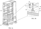
- FIG. 1A schematically illustrates a server rack 10 on a transporting pallet 12.
- Transporting pallet 12 is usually made exclusively of wood, although plastics and wood-based products, such as pressboard, fiberboard, laminated veneer lumber and other wood substitutes, can be employed as the transporting pallet 12.
- Servers 14, 16, 18, etc. are pre-loaded onto the server rack 10 before transportation of the server rack 10 to the data center.
- FIG. 1B illustrates details of the server rack 10 and its rack post 24, beneath which is placed damper 20 and adjustable leveling foot 22. In FIG. 1A , the lower extremity 26 of leveling foot 22 is in engagement with the transporting pallet 12.
- damper 20 can be of varied construction.
- damper 20 can be formed of an elastomeric rubber or rubbery polymer to absorb the vibration imparted to the server rack 10 and servers 14, 16, 18, etc., positioned within the server rack 10, during movement of the server rack 10 and the transporting pallet 12.
- damper 20 can comprise a hydraulic, incompressible fluid that moves between chambers in the manner of a shock absorber.
- damper 20 can take the form of mechanical springs to absorb the vibration energy imparted to the server rack 10 and servers 14, 16, 18, etc., upon transportation to a data center.
- pneumatic fluid can be employed in a shock absorber. Air is the most readily and inexpensive gas to use in a pneumatic shock absorber, but other gasses can be employed in lieu of air, such as nitrogen gas.
- FIG. 2A is another embodiment according to this invention, which as can be seen in the magnified view of FIG. 2B , additionally provides wheels in the form of casters 30, 32. These support the weight of the server rack 10 and servers 14, 16, 18, etc., when the adjustable leveling feet 22, 34 are positioned in their normal, upward position so as to allow the weight of the server rack 10 and servers contained therein, to be carried by the casters 30, 32. It is to be understood that additional wheels and/or casters (not shown) may also be provided to carry the weight of the server rack 10, and servers contained therein, after the servers are moved to or within a data center.
- FIG. 2b illustrates the movement of the damping, leveling feet 22, 34, to an upper position, such that all the weight of the server rack 10, and pre-loaded servers 14, 16, 18, are borne by the casters 30, 32, and not borne by the leveling feet 22, 34.
- FIG. 3A is yet another embodiment according to the disclosure where, as can be seen in the magnified view of FIG. 3B , the adjustable leveling feet 22, 34, are lowered into contact with the transporting pallet 12. In this position, the weight of the server rack 10 and the servers 14, 16, 18, etc., contained within the server rack 10, are transferred from casters 30, 32, to the damper 20 of each of the adjustable leveling feet 22, 34, to absorb the vibration when the transporting pallet 12 to, or within, a data center.
Landscapes
- Engineering & Computer Science (AREA)
- Microelectronics & Electronic Packaging (AREA)
- Computer Hardware Design (AREA)
- General Engineering & Computer Science (AREA)
- Vibration Prevention Devices (AREA)
Abstract
Description
- In order to reduce some of the stress placed upon servers pre-loaded into server racks, an adjustable leveling foot with a damping function is provided under the posts of a server rack to directly absorb vibration when the server rack is transported as a unit. A transporting system and method of transporting pre-loaded servers are also disclosed.
- With data center construction time requirements growing shorter and shorter, a server that is pre-installed in a server rack for transport to the data center, thereby shortening the data center construction lead time, has become a new trend. However, transporting pre-installed servers presents new challenges, such as providing anti-vibration protection to the servers while ensuring adequate strength in the server rack.
- In one embodiment according to this disclosure, an adjustable leveling foot with a damping function is provided under the posts of a server rack upon which servers have been installed.
- In another embodiment of this disclosure, a direct support of the server rack on a transport pallet directly absorbs vibration when the server rack is transported, thereby protecting both the servers and the server rack.
- In a still further embodiment according to this disclosure, an adjustable foot with a damper function is provided under the rack posts, with the adjustable foot being raised to an upper, normal operating position when the server rack is installed. At the same time, the adjustable foot is capable of being moved to a lower transporting position, such that it directly contacts a transporting pallet, thereby protecting both the server and server rack from vibration during transport.
- These and other objects and embodiments of the structure and function of the leveling foot will be understood with reference to the detailed description and the appended drawings.
-
-
FIG. 1A is a schematic illustration of a server rack resting upon a transporting pallet. -
FIG. 1B is a magnified view of a portion ofFIG. 1A to illustrate details of the adjustable leveling foot with a damping function. -
FIG. 2A is a schematic representation of a server rack upon a transporting pallet with the adjustable foot adjusted to its upper, normal position. -
FIG. 2B is a magnified view of a portion ofFIG. 2A to illustrate details of the adjustable leveling foot with a damping function. -
FIG. 3A is a schematic illustration of a server rack resting upon a transporting pallet, with the adjustable leveling foot with a damping function lowered into engagement with the transporting pallet. -
FIG. 3B is a magnified view of a portion ofFIG. 3A to illustrate details of the adjustable leveling foot with a damping function lowered into contact with the transporting pallet. - The present invention is described with reference to the attached figures, wherein like reference numerals are used throughout the figures to designate similar or equivalent elements. The figures are not drawn to scale and are provided merely to illustrate the instant invention. Several aspects of the invention are described below with reference to example applications for illustration. It should be understood that numerous specific details, relationships, and methods are set forth to provide a full understanding of the invention. One having ordinary skill in the relevant art, however, will readily recognize that the invention can be practiced without one or more of the specific details, or with other methods. In other instances, well-known structures or operations are not shown in detail to avoid obscuring the invention. The present invention is not limited by the illustrated ordering of acts or events, as some acts may occur in different orders and/or concurrently with other acts or events. Furthermore, not all illustrated acts or events are required to implement a methodology in accordance with the present invention.
- In order to meet the accelerated construction schedules of data centers, it has been proposed that servers be installed into the server racks before transporting the server racks to the data center. While this procedure is becoming a new trend to hasten the construction of data centers, the transportation of both the servers installed in the server rack, and the server rack itself, exposes both to vibration.
-
FIG. 1A schematically illustrates aserver rack 10 on a transportingpallet 12.Transporting pallet 12 is usually made exclusively of wood, although plastics and wood-based products, such as pressboard, fiberboard, laminated veneer lumber and other wood substitutes, can be employed as the transportingpallet 12.Servers server rack 10 before transportation of theserver rack 10 to the data center.FIG. 1B illustrates details of theserver rack 10 and itsrack post 24, beneath which is placeddamper 20 and adjustable levelingfoot 22. InFIG. 1A , thelower extremity 26 of levelingfoot 22 is in engagement with the transportingpallet 12. An adjustment device, such as levelingfoot 28, which can be threadedly rotated to adjust the position oflower extremity 26, can move thelower extremity 26 into, or out of contact with transportingpallet 12. In addition to the rotation of the threads to adjust the levelingfoot 22, other mechanisms, such as a lever, can be employed to adjust the levelingfoot 22. Thedamper 20 can be of varied construction. For example,damper 20 can be formed of an elastomeric rubber or rubbery polymer to absorb the vibration imparted to theserver rack 10 andservers server rack 10, during movement of theserver rack 10 and the transportingpallet 12. Alternatively,damper 20 can comprise a hydraulic, incompressible fluid that moves between chambers in the manner of a shock absorber. Still further,damper 20 can take the form of mechanical springs to absorb the vibration energy imparted to theserver rack 10 andservers -
FIG. 2A is another embodiment according to this invention, which as can be seen in the magnified view ofFIG. 2B , additionally provides wheels in the form ofcasters server rack 10 andservers feet server rack 10 and servers contained therein, to be carried by thecasters server rack 10, and servers contained therein, after the servers are moved to or within a data center.FIG. 2b illustrates the movement of the damping, levelingfeet server rack 10, and pre-loadedservers casters feet -
FIG. 3A is yet another embodiment according to the disclosure where, as can be seen in the magnified view ofFIG. 3B , the adjustable levelingfeet pallet 12. In this position, the weight of theserver rack 10 and theservers server rack 10, are transferred fromcasters damper 20 of each of theadjustable leveling feet pallet 12 to, or within, a data center. - The terminology used herein is for the purpose of describing particular embodiments only and is not intended to be limiting of the invention. As used herein, the singular forms "a," "an," and "the" are intended to include the plural forms as well, unless the context clearly indicates otherwise. Furthermore, to the extent that the terms "including," "includes," "having," "has," "with," or variants thereof, are used in either the detailed description and/or the claims, such terms are intended to be inclusive in a manner similar to the term "comprising."
- Unless otherwise defined, all terms (including technical and scientific terms) used herein have the same meaning as commonly understood by one of ordinary skill in the art. Furthermore, terms, such as those defined in commonly used dictionaries, should be interpreted as having a meaning that is consistent with their meaning in the context of the relevant art, and will not be interpreted in an idealized or overly formal sense unless expressly so defined herein.
Claims (15)
- A server rack (10) into which one or more servers (14, 16, 18) can be installed, the server rack (10) comprising:a post at a lower end of the server rack (10); anda damper mounted on the post.
- The server rack (10) of claim 1, further comprising at least one foot (22, 28, 34), wherein the damper is positioned between the post and foot (22, 28, 34).
- The server rack (10) of claim 2, further comprising at least one wheel and at least one caster (30, 32) mounted on said rack.
- A server rack moving system comprising:a server rack (10) according to claim 1, in combination with a transporting pallet (12) upon which the server rack (10) rests.
- The server rack moving system according to claim 4, further comprising at least one wheel mounted on said server rack (10).
- A method of pre-installing servers (14, 16, 18) into a server rack (10) prior to moving the server rack (10) into a data center, the method comprising:providing a server rack (10) with servers (14, 16, 18) pre-installed in the rack;combining the server rack (10) with a transporting pallet (12) to transport the server rack (10) and servers (14, 16, 18) installed to, to or into a data center; andproviding a damper (20) between the server rack (10) and the transporting pallet (12).
- The method of claim 6, further comprising posts extending from a lowermost portion of the server rack (10), and positioning the damper (20) on the posts.
- The method of claim 7, further comprising providing adjustable feet (22, 28, 34) between the damper (20) and the transporting pallet (12).
- The method of claim 8, further comprising providing a plurality of wheels on a lowermost portion of the server rack (10).
- The method of claim 9, further comprising adjusting the adjustable feet (22, 28, 34) such that all of the weight of the servers (14, 16, 18) and the server rack (10) are borne by the dampers (20), and not borne by the wheels.
- The method according to claim 10, further comprising adjusting the adjustable feet (22, 28, 34) such that all the weight of the servers (14, 16, 18) and server rack (10) are borne by the wheels, and not borne by the feet (22, 28, 34).
- The method according to claim 11, wherein the adjusting step in which the weight of the servers and server rack are borne by the wheels, and not borne by the feet, is performed after moving the server rack into a data center.
- A server rack (10), comprising a lowermost portion of the server rack (10) being provided with adjustable feet (22, 28, 34) and a plurality of wheels, wherein each of the adjustable feet (22, 28, 34) is provided with a damper to absorb vibration energy, the damper being positioned between the server rack (10) and each of the feet (22, 28, 34).
- The server rack (10) according to claim 13, wherein the lowermost portion of the server rack (10) is provided with a plurality of posts, and the damper is positioned on each post.
- The server rack (10) of claim 14, in combination with a transporting pallet (12), wherein the adjustable feet (22, 28, 34), and not the wheels, are in contact with the transporting pallet (12).
Applications Claiming Priority (2)
| Application Number | Priority Date | Filing Date | Title |
|---|---|---|---|
| US201862623723P | 2018-01-30 | 2018-01-30 | |
| US15/989,406 US10398046B2 (en) | 2018-01-30 | 2018-05-25 | Server rack with damping post |
Publications (1)
| Publication Number | Publication Date |
|---|---|
| EP3518636A1 true EP3518636A1 (en) | 2019-07-31 |
Family
ID=63722243
Family Applications (1)
| Application Number | Title | Priority Date | Filing Date |
|---|---|---|---|
| EP18198231.5A Withdrawn EP3518636A1 (en) | 2018-01-30 | 2018-10-02 | Server rack with damping post |
Country Status (5)
| Country | Link |
|---|---|
| US (1) | US10398046B2 (en) |
| EP (1) | EP3518636A1 (en) |
| JP (1) | JP2019133629A (en) |
| CN (1) | CN110099534A (en) |
| TW (1) | TWI669044B (en) |
Families Citing this family (7)
| Publication number | Priority date | Publication date | Assignee | Title |
|---|---|---|---|---|
| US11229139B2 (en) | 2019-10-23 | 2022-01-18 | Dell Products, L.P. | Isolating information handling system racks from shock and vibration in a modular data center |
| CN110783828B (en) * | 2019-12-09 | 2023-07-25 | 中铁十二局集团有限公司 | Railway signal damping type electric power cabinet |
| EP4142441B1 (en) * | 2021-08-30 | 2024-05-15 | Ovh | Rack system for a data center |
| CN113973459B (en) * | 2021-10-29 | 2023-04-14 | 东莞祥科智控装备有限公司 | Heat recovery switch board |
| US11903170B2 (en) | 2021-12-16 | 2024-02-13 | International Business Machines Corporation | Temporary structural bulkhead in an electronic enclosure |
| TWI808906B (en) * | 2022-10-06 | 2023-07-11 | 緯穎科技服務股份有限公司 | Transport mechanism of server rack and pallet structure |
| US12464638B2 (en) * | 2023-02-28 | 2025-11-04 | Hyve Solutions Corporation | Vibration dampening for high-density storage system structure |
Citations (5)
| Publication number | Priority date | Publication date | Assignee | Title |
|---|---|---|---|---|
| JPH09181459A (en) * | 1995-12-26 | 1997-07-11 | Kofu Nippon Denki Kk | Seismic isolation structure of frame |
| US20120113570A1 (en) * | 2010-11-05 | 2012-05-10 | Inventec Corporation | Server cabinet structure with vibration isolation function |
| CN203722947U (en) * | 2013-12-27 | 2014-07-16 | 联方云天科技(北京)有限公司 | A container data center cabinet damping system |
| US20150351535A9 (en) * | 2013-09-11 | 2015-12-10 | Roche Diagnostics Operations, Inc. | Installation of analytical apparatus |
| US20160107793A1 (en) * | 2014-10-15 | 2016-04-21 | Wistron Corporation | Server packing assembly |
Family Cites Families (21)
| Publication number | Priority date | Publication date | Assignee | Title |
|---|---|---|---|---|
| US5684671A (en) * | 1995-08-22 | 1997-11-04 | Sequent Computer Systems, Inc. | Packaging architecture for a data server |
| TW437980U (en) * | 1999-06-09 | 2001-05-28 | Twinhead Int Corp | Shockproof apparatus for notebook computer module |
| JP2002290100A (en) * | 2001-03-28 | 2002-10-04 | Fuji Mach Mfg Co Ltd | Electronic component mounting system |
| US7120013B1 (en) * | 2003-04-11 | 2006-10-10 | Raytheon Company | System and method for transferring large amounts of stored data |
| US7461849B2 (en) | 2005-12-22 | 2008-12-09 | Emiph, Llc | Method and apparatus for an electronic equipment rack |
| GB0521786D0 (en) * | 2005-10-26 | 2005-12-07 | Meehan Gerard M | Mobile garment carrier |
| TW200823144A (en) | 2006-11-20 | 2008-06-01 | Chien-Kuo Liang | Weight-carrying controller |
| US7616436B2 (en) * | 2007-05-17 | 2009-11-10 | Dell Products L.P. | Systems and methods for mounting components of an information handling system |
| US7478819B1 (en) * | 2008-03-27 | 2009-01-20 | International Business Machines Corporation | Forced extension caster assembly |
| TW201143583A (en) | 2010-05-18 | 2011-12-01 | Hon Hai Prec Ind Co Ltd | Stack plate and server assembly using the same |
| TWI411375B (en) * | 2011-06-21 | 2013-10-01 | Quanta Comp Inc | Rack server system |
| TWM419141U (en) * | 2011-08-11 | 2011-12-21 | Quanta Comp Inc | Server system |
| CN104349621A (en) * | 2013-08-01 | 2015-02-11 | 上海同悦信息科技有限公司 | Server machine cabinet capable of being conveniently installed |
| TWM479492U (en) | 2013-12-18 | 2014-06-01 | Echostreams Innovative Solutions Llc | Server chassis |
| TW201534198A (en) * | 2014-02-18 | 2015-09-01 | Quanta Comp Inc | Server device |
| US9291234B1 (en) * | 2014-08-28 | 2016-03-22 | International Business Machines Corporation | Load adapting vibration isolation pallet mechanisms |
| US9832912B2 (en) * | 2015-05-07 | 2017-11-28 | Dhk Storage, Llc | Computer server heat regulation utilizing integrated precision air flow |
| US10069625B2 (en) * | 2015-09-22 | 2018-09-04 | Quanta Computer Inc. | System and method for automatic key generation for self-encrypting drives |
| US9955608B2 (en) * | 2016-03-17 | 2018-04-24 | Dell Products L.P. | Rack anti-tip system |
| CN205509330U (en) * | 2016-04-18 | 2016-08-24 | 国网山东省电力公司郓城县供电公司 | Convenient shock attenuation switch board that removes and fix a position |
| CN205883775U (en) * | 2016-07-15 | 2017-01-11 | 重庆博卓机电有限公司 | Silencer double -end dibit electrical control cabinet for automatic welding machine |
-
2018
- 2018-05-25 US US15/989,406 patent/US10398046B2/en active Active
- 2018-08-08 TW TW107127681A patent/TWI669044B/en active
- 2018-08-29 CN CN201810993484.2A patent/CN110099534A/en active Pending
- 2018-10-02 EP EP18198231.5A patent/EP3518636A1/en not_active Withdrawn
- 2018-10-05 JP JP2018190440A patent/JP2019133629A/en active Pending
Patent Citations (5)
| Publication number | Priority date | Publication date | Assignee | Title |
|---|---|---|---|---|
| JPH09181459A (en) * | 1995-12-26 | 1997-07-11 | Kofu Nippon Denki Kk | Seismic isolation structure of frame |
| US20120113570A1 (en) * | 2010-11-05 | 2012-05-10 | Inventec Corporation | Server cabinet structure with vibration isolation function |
| US20150351535A9 (en) * | 2013-09-11 | 2015-12-10 | Roche Diagnostics Operations, Inc. | Installation of analytical apparatus |
| CN203722947U (en) * | 2013-12-27 | 2014-07-16 | 联方云天科技(北京)有限公司 | A container data center cabinet damping system |
| US20160107793A1 (en) * | 2014-10-15 | 2016-04-21 | Wistron Corporation | Server packing assembly |
Also Published As
| Publication number | Publication date |
|---|---|
| TW201933968A (en) | 2019-08-16 |
| US10398046B2 (en) | 2019-08-27 |
| TWI669044B (en) | 2019-08-11 |
| US20190239370A1 (en) | 2019-08-01 |
| JP2019133629A (en) | 2019-08-08 |
| CN110099534A (en) | 2019-08-06 |
Similar Documents
| Publication | Publication Date | Title |
|---|---|---|
| US10398046B2 (en) | Server rack with damping post | |
| US7249442B2 (en) | Storage rack vibration isolators and related storage rack systems | |
| JP2818748B2 (en) | Pallet for transporting cargo and method of unloading cargo from pallet | |
| US7263806B2 (en) | Storage rack vibration isolators and related storage racks | |
| CN205132076U (en) | A shock-absorbing tray with adjustable cushioning performance | |
| US8166963B2 (en) | Accessory platform for archery bows | |
| KR101438161B1 (en) | Probe card container | |
| US5626231A (en) | Crate and pallet assembly | |
| KR101081681B1 (en) | Moving cart of semiconductor equipment | |
| CN105620946A (en) | Server packaging assembly | |
| JP2007187595A (en) | Drop test device | |
| TWI804605B (en) | Sliding seismic isolator, seismic isolation system, and method of supporting structure for seismic isolation and re-centering | |
| CN108263924A (en) | A kind of elevator shock-absorbing device | |
| JP2014141314A (en) | Vibration control structure of rack warehouse and vibration damping method of existing rack warehouse | |
| JP3770381B2 (en) | Method for forming base support | |
| US20230182956A1 (en) | Shock-absorbing pallets for transporting servers | |
| CN112936202B (en) | Solid launch vehicle assembly rack | |
| CN206378189U (en) | Vibration-absorbing balance table | |
| CN101155966B (en) | Storage rack vibration isolators and related storage rack systems | |
| CN213669400U (en) | Shock attenuation sky platform | |
| CN211995781U (en) | Transfer device for stereoscopic warehouse | |
| KR102524376B1 (en) | Wooden Furniture Edge Finishing Device | |
| CN220974919U (en) | Wood support with anti-impact function | |
| US6966535B2 (en) | Snubber for pneumatically isolated platforms | |
| EP4642703A2 (en) | Skids for loads with castor wheels |
Legal Events
| Date | Code | Title | Description |
|---|---|---|---|
| PUAI | Public reference made under article 153(3) epc to a published international application that has entered the european phase |
Free format text: ORIGINAL CODE: 0009012 |
|
| STAA | Information on the status of an ep patent application or granted ep patent |
Free format text: STATUS: THE APPLICATION HAS BEEN PUBLISHED |
|
| AK | Designated contracting states |
Kind code of ref document: A1 Designated state(s): AL AT BE BG CH CY CZ DE DK EE ES FI FR GB GR HR HU IE IS IT LI LT LU LV MC MK MT NL NO PL PT RO RS SE SI SK SM TR |
|
| AX | Request for extension of the european patent |
Extension state: BA ME |
|
| STAA | Information on the status of an ep patent application or granted ep patent |
Free format text: STATUS: REQUEST FOR EXAMINATION WAS MADE |
|
| 17P | Request for examination filed |
Effective date: 20191227 |
|
| RBV | Designated contracting states (corrected) |
Designated state(s): AL AT BE BG CH CY CZ DE DK EE ES FI FR GB GR HR HU IE IS IT LI LT LU LV MC MK MT NL NO PL PT RO RS SE SI SK SM TR |
|
| STAA | Information on the status of an ep patent application or granted ep patent |
Free format text: STATUS: EXAMINATION IS IN PROGRESS |
|
| 17Q | First examination report despatched |
Effective date: 20211102 |
|
| STAA | Information on the status of an ep patent application or granted ep patent |
Free format text: STATUS: THE APPLICATION HAS BEEN WITHDRAWN |
|
| 18W | Application withdrawn |
Effective date: 20211203 |